EP4108536A1 - Control method and device for driver assistance - Google Patents
Control method and device for driver assistance Download PDFInfo
- Publication number
- EP4108536A1 EP4108536A1 EP22165735.6A EP22165735A EP4108536A1 EP 4108536 A1 EP4108536 A1 EP 4108536A1 EP 22165735 A EP22165735 A EP 22165735A EP 4108536 A1 EP4108536 A1 EP 4108536A1
- Authority
- EP
- European Patent Office
- Prior art keywords
- road
- information
- safe
- vehicle
- curvature
- Prior art date
- Legal status (The legal status is an assumption and is not a legal conclusion. Google has not performed a legal analysis and makes no representation as to the accuracy of the status listed.)
- Granted
Links
Images
Classifications
-
- B—PERFORMING OPERATIONS; TRANSPORTING
- B60—VEHICLES IN GENERAL
- B60W—CONJOINT CONTROL OF VEHICLE SUB-UNITS OF DIFFERENT TYPE OR DIFFERENT FUNCTION; CONTROL SYSTEMS SPECIALLY ADAPTED FOR HYBRID VEHICLES; ROAD VEHICLE DRIVE CONTROL SYSTEMS FOR PURPOSES NOT RELATED TO THE CONTROL OF A PARTICULAR SUB-UNIT
- B60W50/00—Details of control systems for road vehicle drive control not related to the control of a particular sub-unit, e.g. process diagnostic or vehicle driver interfaces
- B60W50/08—Interaction between the driver and the control system
- B60W50/14—Means for informing the driver, warning the driver or prompting a driver intervention
-
- B—PERFORMING OPERATIONS; TRANSPORTING
- B60—VEHICLES IN GENERAL
- B60W—CONJOINT CONTROL OF VEHICLE SUB-UNITS OF DIFFERENT TYPE OR DIFFERENT FUNCTION; CONTROL SYSTEMS SPECIALLY ADAPTED FOR HYBRID VEHICLES; ROAD VEHICLE DRIVE CONTROL SYSTEMS FOR PURPOSES NOT RELATED TO THE CONTROL OF A PARTICULAR SUB-UNIT
- B60W40/00—Estimation or calculation of non-directly measurable driving parameters for road vehicle drive control systems not related to the control of a particular sub unit, e.g. by using mathematical models
- B60W40/02—Estimation or calculation of non-directly measurable driving parameters for road vehicle drive control systems not related to the control of a particular sub unit, e.g. by using mathematical models related to ambient conditions
- B60W40/06—Road conditions
- B60W40/072—Curvature of the road
-
- B—PERFORMING OPERATIONS; TRANSPORTING
- B60—VEHICLES IN GENERAL
- B60W—CONJOINT CONTROL OF VEHICLE SUB-UNITS OF DIFFERENT TYPE OR DIFFERENT FUNCTION; CONTROL SYSTEMS SPECIALLY ADAPTED FOR HYBRID VEHICLES; ROAD VEHICLE DRIVE CONTROL SYSTEMS FOR PURPOSES NOT RELATED TO THE CONTROL OF A PARTICULAR SUB-UNIT
- B60W40/00—Estimation or calculation of non-directly measurable driving parameters for road vehicle drive control systems not related to the control of a particular sub unit, e.g. by using mathematical models
- B60W40/10—Estimation or calculation of non-directly measurable driving parameters for road vehicle drive control systems not related to the control of a particular sub unit, e.g. by using mathematical models related to vehicle motion
- B60W40/105—Speed
-
- B—PERFORMING OPERATIONS; TRANSPORTING
- B60—VEHICLES IN GENERAL
- B60W—CONJOINT CONTROL OF VEHICLE SUB-UNITS OF DIFFERENT TYPE OR DIFFERENT FUNCTION; CONTROL SYSTEMS SPECIALLY ADAPTED FOR HYBRID VEHICLES; ROAD VEHICLE DRIVE CONTROL SYSTEMS FOR PURPOSES NOT RELATED TO THE CONTROL OF A PARTICULAR SUB-UNIT
- B60W50/00—Details of control systems for road vehicle drive control not related to the control of a particular sub-unit, e.g. process diagnostic or vehicle driver interfaces
- B60W50/08—Interaction between the driver and the control system
- B60W50/14—Means for informing the driver, warning the driver or prompting a driver intervention
- B60W2050/143—Alarm means
-
- B—PERFORMING OPERATIONS; TRANSPORTING
- B60—VEHICLES IN GENERAL
- B60W—CONJOINT CONTROL OF VEHICLE SUB-UNITS OF DIFFERENT TYPE OR DIFFERENT FUNCTION; CONTROL SYSTEMS SPECIALLY ADAPTED FOR HYBRID VEHICLES; ROAD VEHICLE DRIVE CONTROL SYSTEMS FOR PURPOSES NOT RELATED TO THE CONTROL OF A PARTICULAR SUB-UNIT
- B60W2520/00—Input parameters relating to overall vehicle dynamics
- B60W2520/10—Longitudinal speed
-
- B—PERFORMING OPERATIONS; TRANSPORTING
- B60—VEHICLES IN GENERAL
- B60W—CONJOINT CONTROL OF VEHICLE SUB-UNITS OF DIFFERENT TYPE OR DIFFERENT FUNCTION; CONTROL SYSTEMS SPECIALLY ADAPTED FOR HYBRID VEHICLES; ROAD VEHICLE DRIVE CONTROL SYSTEMS FOR PURPOSES NOT RELATED TO THE CONTROL OF A PARTICULAR SUB-UNIT
- B60W2552/00—Input parameters relating to infrastructure
- B60W2552/30—Road curve radius
-
- B—PERFORMING OPERATIONS; TRANSPORTING
- B60—VEHICLES IN GENERAL
- B60W—CONJOINT CONTROL OF VEHICLE SUB-UNITS OF DIFFERENT TYPE OR DIFFERENT FUNCTION; CONTROL SYSTEMS SPECIALLY ADAPTED FOR HYBRID VEHICLES; ROAD VEHICLE DRIVE CONTROL SYSTEMS FOR PURPOSES NOT RELATED TO THE CONTROL OF A PARTICULAR SUB-UNIT
- B60W2555/00—Input parameters relating to exterior conditions, not covered by groups B60W2552/00, B60W2554/00
- B60W2555/60—Traffic rules, e.g. speed limits or right of way
-
- B—PERFORMING OPERATIONS; TRANSPORTING
- B60—VEHICLES IN GENERAL
- B60W—CONJOINT CONTROL OF VEHICLE SUB-UNITS OF DIFFERENT TYPE OR DIFFERENT FUNCTION; CONTROL SYSTEMS SPECIALLY ADAPTED FOR HYBRID VEHICLES; ROAD VEHICLE DRIVE CONTROL SYSTEMS FOR PURPOSES NOT RELATED TO THE CONTROL OF A PARTICULAR SUB-UNIT
- B60W2556/00—Input parameters relating to data
- B60W2556/40—High definition maps
-
- B—PERFORMING OPERATIONS; TRANSPORTING
- B60—VEHICLES IN GENERAL
- B60W—CONJOINT CONTROL OF VEHICLE SUB-UNITS OF DIFFERENT TYPE OR DIFFERENT FUNCTION; CONTROL SYSTEMS SPECIALLY ADAPTED FOR HYBRID VEHICLES; ROAD VEHICLE DRIVE CONTROL SYSTEMS FOR PURPOSES NOT RELATED TO THE CONTROL OF A PARTICULAR SUB-UNIT
- B60W2556/00—Input parameters relating to data
- B60W2556/45—External transmission of data to or from the vehicle
- B60W2556/50—External transmission of data to or from the vehicle of positioning data, e.g. GPS [Global Positioning System] data
Definitions
- the disclosure relates to the field of control for driver assistance, and in particular, to a control method and device for driver assistance, a computer storage medium, and a vehicle.
- a control method for driver assistance including: receiving positioning information of a vehicle; obtaining information about a road structure ahead of the vehicle based on the positioning information; and determining, based on the information about the road structure, whether an alarm for a sharp bend is needed.
- the determining, based on the information about the road structure, whether an alarm for a sharp bend is needed includes: calculating a safe radius of curvature based on the information about the road structure; and determining, based on the safe radius of curvature, whether the alarm for a sharp bend is needed.
- the calculating a safe radius of curvature based on the information about the road structure includes: calculating a minimum value of a safe sight distance on a road; and calculating the safe radius of curvature based on the information about the road structure and the minimum value of the safe sight distance on the road.
- the calculating a minimum value of a safe sight distance on a road includes: calculating the minimum value of the safe sight distance on the road based on a value of a speed limit on the road or an actual vehicle speed of a current vehicle.
- the determining, based on the safe radius of curvature, whether the alarm for a sharp bend is needed includes: determining, when an actual radius of curvature of the road is less than the safe radius of curvature, that the alarm for a sharp bend is needed.
- the information about the road structure includes one or more of the actual radius of curvature of the road, a lane width, lane data, and a lane structure.
- a control device for driver assistance including: a receiving apparatus configured to receive positioning information of a vehicle; an obtaining apparatus configured to obtain information about a road structure ahead of the vehicle based on the positioning information; and a determination apparatus configured to determine, based on the information about the road structure, whether an alarm for a sharp bend is needed.
- the determination apparatus includes: a calculation unit configured to calculate a safe radius of curvature based on the information about the road structure; and a determination unit configured to determine, based on the safe radius of curvature, whether the alarm for a sharp bend is needed.
- the calculation unit is configured to: calculate a minimum value of a safe sight distance on a road; and calculate the safe radius of curvature based on the information about the road structure and the minimum value of the safe sight distance on the road.
- the calculation unit is configured to: calculate the minimum value of the safe sight distance on the road based on a value of a speed limit on the road or an actual vehicle speed of a current vehicle.
- the determination apparatus is configured to: determine, when an actual radius of curvature of the road is less than the safe radius of curvature, that the alarm for a sharp bend is needed.
- the information about the road structure includes one or more of the actual radius of curvature of the road, a lane width, lane data, and a lane structure.
- a computer storage medium including instructions, where when the instructions are run, the method as described above is performed.
- a vehicle including the device as described above.
- the positioning information of the vehicle is received, and the information about the road structure ahead of the vehicle is obtained based on the positioning information, such that it can be determined whether the alarm for a sharp bend is needed.
- the solution fills the gaps in dealing with sharp bends in the field of autonomous driving, and can allow for effective pre-warning of an environment with a sharp bend (and/or corresponding control of deceleration), thereby greatly reducing the accident rates on roads with sharp bends.
- control logic of the disclosure may be included on a computer-readable medium as executable program instructions, which are implemented by a processor or the like.
- the computer-readable medium include, but are not limited to, a ROM, a RAM, an optical disc, a magnetic tape, a floppy disk, a flash drive, a smart card, and an optical data storage apparatus.
- a computer-readable recording medium may also be distributed in a computer system connected to a network, so that the computer-readable medium is stored and implemented in a distributed manner, for example, through a vehicle telematics service or a controller area network (CAN).
- CAN controller area network
- vehicle or another similar term used herein includes general motor vehicles, such as passenger vehicles (including sport utility vehicles, buses, trucks, etc.) and various commercial vehicles, and includes hybrid vehicles, electric vehicles, etc.
- a hybrid vehicle is a vehicle with two or more power sources, such as a vehicle powered by a gasoline engine and an electric motor.
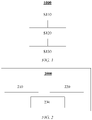
- FIG. 1 is a schematic flowchart of a control method 1000 for driver assistance according to an embodiment of the disclosure. As shown in FIG. 1 , the control method 1000 for driver assistance includes the following steps:
- the "positioning information of a vehicle” may also be referred to as position information of the vehicle, where the information is used to signify a real-time position and/or a motion trajectory of the current vehicle.
- the positioning information of the vehicle may be obtained by using a global positioning system (GPS).
- GPS global positioning system
- the positioning information of the vehicle includes not only GPS information of the vehicle, and also includes lane navigation information.
- information about a road structure is various information for description of the road structure, which, for example, may be obtained from a high-definition map.
- the information about the road structure includes one or more of the actual radius of curvature of the road, a lane width, lane data, and a lane structure.
- the obtaining information about a road structure ahead of the vehicle based on the positioning information in step S 120 may include: searching and obtaining, based on the GPS information of the vehicle and the lane navigation information, road information on a high-definition map within a certain distance (for example, 2 km or 2.5 km, or within the range of other distances) ahead of a moving path in a lane, where the road information includes a road curvature, a lane width, lane data, a lane structure, and other necessary information about the road structure.
- step S130 may include: calculating a safe radius of curvature based on the information about the road structure; and determining, based on the safe radius of curvature, whether the alarm for a sharp bend is needed.
- the calculating a safe radius of curvature based on the information about the road structure includes: calculating a minimum value of a safe sight distance on a road; and calculating the safe radius of curvature based on the information about the road structure and the minimum value of the safe sight distance on the road.
- the determining, based on the safe radius of curvature, whether the alarm for a sharp bend is needed includes: determining, when an actual radius of curvature of the road is less than the safe radius of curvature, that the alarm for a sharp bend is needed.
- safe radius of curvature in the context of the disclosure includes not only a safe radius of curvature estimated based on the information about the road structure and the minimum value of the safe sight distance on the road, and also includes a minimum radius of curvature of a circular curve of this section of road that is calculated based on the value of the speed limit on the road and that complies with national laws and regulations.
- a value of a safe sight distance required for driving on this section of road may be calculated based on the value of the speed limit on the road.
- L minRoadspdLim is a minimum safe sight distance calculated based on a speed limit on the road
- spd roadLim is a value of the speed limit on the road provided on a high-definition map.
- the above formula is merely a specific example, and constant parameters in the formula may be changed according to actual engineering requirements.
- L min is the minimum value of the safe sight distance on the road
- W is a width value of the road.
- control method 1000 for driver assistance may be implemented by a computer program.
- a computer storage medium such as a USB flash drive
- the control method for driver assistance according to one or more embodiments of the disclosure can be performed by running the computer program.
- FIG. 2 is a schematic structural diagram of a control device 2000 for driver assistance according to an embodiment of the disclosure.
- the control device 2000 for driver assistance includes a receiving apparatus 210, an obtaining apparatus 220, and a determination apparatus 230.
- the receiving apparatus 210 is configured to receive positioning information of a vehicle;
- the obtaining apparatus 220 is configured to obtain information about a road structure ahead of the vehicle based on the positioning information;
- the determination apparatus 230 is configured to determine, based on the information about the road structure, whether an alarm for a sharp bend is needed.
- the "positioning information of a vehicle” may also be referred to as position information of the vehicle, where the information is used to signify a real-time position and/or a motion trajectory of the current vehicle.
- the positioning information of the vehicle may be obtained by using a global positioning system (GPS).
- GPS global positioning system
- the positioning information of the vehicle includes not only GPS information of the vehicle, and also includes lane navigation information.
- information about a road structure is various information for description of the road structure, which, for example, may be obtained from a high-definition map.
- the information about the road structure includes one or more of the actual radius of curvature of the road, a lane width, lane data, and a lane structure.
- the obtaining apparatus 220 may be configured to search and obtain, based on the GPS information of the vehicle and the lane navigation information, road information on a high-definition map within a certain distance (for example, 2 km or 2.5 km, or within the range of other distances) ahead of a moving path in a lane, where the road information includes a road curvature, a lane width, lane data, a lane structure, and other necessary information about the road structure.
- the determination apparatus 230 includes: a calculation unit configured to calculate a safe radius of curvature based on the information about the road structure; and a determination unit configured to determine, based on the safe radius of curvature, whether the alarm for a sharp bend is needed.
- the calculation unit is configured to: calculate a minimum value of a safe sight distance on a road; and calculate the safe radius of curvature based on the information about the road structure and the minimum value of the safe sight distance on the road.
- the determination unit is configured to determine, when an actual radius of curvature of the road is less than the safe radius of curvature, that the alarm for a sharp bend is needed.
- safe radius of curvature in the context of the disclosure includes not only a safe radius of curvature estimated based on the information about the road structure and the minimum value of the safe sight distance on the road, and also includes a minimum radius of curvature of a circular curve of this section of road that is calculated based on the value of the speed limit on the road and that complies with national laws and regulations.
- the calculation unit may be configured to calculate a value of a safe sight distance required for driving on this section of road based on a value of an actual vehicle speed of the present vehicle.
- the above formula is merely a specific example, and constant parameters in the formula may be changed according to actual engineering requirements.
- R L min 2 2 W + W 2 .
- the control device 2000 for driver assistance may be integrated in ADAS systems.
- ADAS systems may also be referred to as advanced driver assistance systems.
- the advanced driver assistance systems use a variety of sensors (such as a millimeter-wave radar, a laser radar, a monocular/binocular camera, and satellite navigation) mounted on an automobile to sense the surrounding environment at any time during traveling of the automobile, collect data, identify, monitor, and track a still/moving object, and perform system operations and analysis in combination with navigation map data, allowing for a driver to be aware of potential dangers in advance, thereby effectively improving the comfort and safety of the automobile during traveling.
- sensors such as a millimeter-wave radar, a laser radar, a monocular/binocular camera, and satellite navigation
- the advanced driver assistance systems include a traffic message channel (TMC) system, an intelligent speed adaptation or intelligent speed advice (ISA) system, a vehicular communication system, an adaptive cruise control (ACC) system, a lane departure warning system (LDWS), a lane keeping assistance system, a collision avoidance system or a pre-crash system, a night vision system, an adaptive light control system, a pedestrian protection system, an automatic parking system, a traffic sign recognition system, a blind spot detection system, a driver drowsiness detection system, a hill descent control system, and an electric vehicle warning sounds system.
- TMC traffic message channel
- ISA intelligent speed adaptation or intelligent speed advice
- ACC adaptive cruise control
- LDWS lane departure warning system
- a collision avoidance system or a pre-crash system a night vision system
- an adaptive light control system a pedestrian protection system
- an automatic parking system a traffic sign recognition system
- a blind spot detection system a driver drowsiness detection system
- a hill descent control system a hill descent control
- control device 2000 for driver assistance is included in a controller of ADAS.
- Various control operations within the control device 2000 for driver assistance may be performed periodically, and a performance period may be dependent on an operation period of the controller of ADAS.
- road information within a given distance (that may be calibrated as needed) ahead of the vehicle may be traversed, and a minimum value of a safe sight distance on a road is then estimated.
- a required safe radius of curvature may be further estimated based on information about a road structure. For example, in a conservative solution, it may be required that there still should be a sufficient sight distance for safety when the vehicle travels in the innermost lane on a bend.
- R min ⁇ 0.001 ⁇ spd roadLim 3 + 0.3393 ⁇ spd roadLim 2 ⁇ 21.369 ⁇ spd roadLim + 480 , where spd roadLim represents the value of the speed limit on the road.
- a value of a radius of curvature of the road R road provided on a high-definition map should not be less than R min , that is, R road ⁇ R min
- different warning or alarm conditions may be selected according to different situations. For example, upon selection of a conservative warning condition, a warning may be sent when any one of the inequation 1, the inequation 2, and the inequation 5 cannot be satisfied. For another example, upon selection of an aggressive warning condition, a warning may be sent when any one of the inequation 3, the inequation 4, and the inequation 5 cannot be satisfied.
- the positioning information of the vehicle is received, and the information about the road structure ahead of the vehicle is obtained based on the positioning information, such that it can be determined whether the alarm for a sharp bend is needed.
- the solution fills the gaps in dealing with sharp bends in the field of autonomous driving, and can allow for effective pre-warning of an environment with a sharp bend (and/or corresponding control of deceleration), thereby greatly reducing the accident rates on roads with sharp bends and improving driving safety.
Landscapes
- Engineering & Computer Science (AREA)
- Automation & Control Theory (AREA)
- Transportation (AREA)
- Mechanical Engineering (AREA)
- Physics & Mathematics (AREA)
- Mathematical Physics (AREA)
- Human Computer Interaction (AREA)
- Traffic Control Systems (AREA)
Abstract
Description
- The disclosure relates to the field of control for driver assistance, and in particular, to a control method and device for driver assistance, a computer storage medium, and a vehicle.
- During everyday driving, a specific proportion of traffic accidents happen on bends or other traffic scenarios with a poor field of vision. On the bends, a driver usually observes an external environment by himself/herself, determines how the environment is, and then performs a corresponding driving operation (for example, deceleration).
- However, in a scenario in which a field of vision is limited due to a bend, a driver observing an external environment simply by himself/herself tends to make an erroneous determination and drives a vehicle into a bend at an excessively high speed, which poses potential safety risks.
- According to an aspect of the disclosure, there is provided a control method for driver assistance, the method including: receiving positioning information of a vehicle; obtaining information about a road structure ahead of the vehicle based on the positioning information; and determining, based on the information about the road structure, whether an alarm for a sharp bend is needed.
- As a supplement or an alternative to the above solution, in the above method, the determining, based on the information about the road structure, whether an alarm for a sharp bend is needed includes: calculating a safe radius of curvature based on the information about the road structure; and determining, based on the safe radius of curvature, whether the alarm for a sharp bend is needed.
- As a supplement or an alternative to the above solution, in the above method, the calculating a safe radius of curvature based on the information about the road structure includes: calculating a minimum value of a safe sight distance on a road; and calculating the safe radius of curvature based on the information about the road structure and the minimum value of the safe sight distance on the road.
- As a supplement or an alternative to the above solution, in the above method, the calculating a minimum value of a safe sight distance on a road includes: calculating the minimum value of the safe sight distance on the road based on a value of a speed limit on the road or an actual vehicle speed of a current vehicle.
- As a supplement or an alternative to the above solution, in the above method, the minimum value Lmin of the safe sight distance on the road is calculated according to the following formula: L min = 0.08 * spd 2 + 0.8393 * spd - 6, where spd is the value of the speed limit on the road or the actual vehicle speed of the current vehicle.
- As a supplement or an alternative to the above solution, in the above method, the calculating the safe radius of curvature based on the information about the road structure and the minimum value of the safe sight distance on the road includes: calculating the safe radius of curvature R according to

- As a supplement or an alternative to the above solution, in the above method, the calculating the safe radius of curvature based on the information about the road structure and the minimum value of the safe sight distance on the road includes: calculating the safe radius of curvature R according to

- As a supplement or an alternative to the above solution, in the above method, the width value W of the road is determined according to the following formula: W = a number of traffic lanes ∗ 3.75 + a number of emergency lanes ∗ 3.5.
- As a supplement or an alternative to the above solution, in the above method, the calculating a safe radius of curvature based on the information about the road structure includes: calculating the safe radius of curvature R based on the value of the speed limit on the road spdroadLim according to


- As a supplement or an alternative to the above solution, in the above method, the determining, based on the safe radius of curvature, whether the alarm for a sharp bend is needed includes: determining, when an actual radius of curvature of the road is less than the safe radius of curvature, that the alarm for a sharp bend is needed.
- As a supplement or an alternative to the above solution, in the above method, the information about the road structure includes one or more of the actual radius of curvature of the road, a lane width, lane data, and a lane structure.
- According to another aspect of the disclosure, there is provided a control device for driver assistance, the device including: a receiving apparatus configured to receive positioning information of a vehicle; an obtaining apparatus configured to obtain information about a road structure ahead of the vehicle based on the positioning information; and a determination apparatus configured to determine, based on the information about the road structure, whether an alarm for a sharp bend is needed.
- As a supplement or an alternative to the above solution, in the above device, the determination apparatus includes: a calculation unit configured to calculate a safe radius of curvature based on the information about the road structure; and a determination unit configured to determine, based on the safe radius of curvature, whether the alarm for a sharp bend is needed.
- As a supplement or an alternative to the above solution, in the above device, the calculation unit is configured to: calculate a minimum value of a safe sight distance on a road; and calculate the safe radius of curvature based on the information about the road structure and the minimum value of the safe sight distance on the road.
- As a supplement or an alternative to the above solution, in the above device, the calculation unit is configured to: calculate the minimum value of the safe sight distance on the road based on a value of a speed limit on the road or an actual vehicle speed of a current vehicle.
- As a supplement or an alternative to the above solution, in the above device, the calculation unit is configured to calculate the minimum value Lmin of the safe sight distance on the road according to the following formula:
L min = 0.08 * spd 2 + 0.8393 * spd - 6, where spd is the value of the speed limit on the road or the actual vehicle speed of the current vehicle. - As a supplement or an alternative to the above solution, in the above device, the calculation unit is configured to calculate the safe radius of curvature R according to the following formula:

- As a supplement or an alternative to the above solution, in the above device, the calculation unit is configured to calculate the safe radius of curvature R according to the following formula:

- As a supplement or an alternative to the above solution, in the above device, the width value W of the road is determined according to the following formula: W = a number of traffic lanes ∗ 3.75 + a number of emergency lanes ∗ 3.5.
- As a supplement or an alternative to the above solution, in the above device, the calculation unit is configured to calculate the safe radius of curvature R based on the value of the speed limit on the road spdroadLim according to the formula R = -0.001 ∗

- As a supplement or an alternative to the above solution, in the above device, the determination apparatus is configured to: determine, when an actual radius of curvature of the road is less than the safe radius of curvature, that the alarm for a sharp bend is needed.
- As a supplement or an alternative to the above solution, in the above device, the information about the road structure includes one or more of the actual radius of curvature of the road, a lane width, lane data, and a lane structure.
- According to still another aspect of the disclosure, there is provided a computer storage medium including instructions, where when the instructions are run, the method as described above is performed.
- According to yet another aspect of the disclosure, there is provided a vehicle, including the device as described above.
- In the control solution for driver assistance according to the embodiments of the disclosure, the positioning information of the vehicle is received, and the information about the road structure ahead of the vehicle is obtained based on the positioning information, such that it can be determined whether the alarm for a sharp bend is needed. The solution fills the gaps in dealing with sharp bends in the field of autonomous driving, and can allow for effective pre-warning of an environment with a sharp bend (and/or corresponding control of deceleration), thereby greatly reducing the accident rates on roads with sharp bends.
- The above and other objectives and advantages of the disclosure will be more thorough and clearer from the following detailed description in conjunction with the accompanying drawings, where the same or similar elements are represented by the same reference numerals.
-
FIG. 1 is a schematic flowchart of a control method for driver assistance according to an embodiment of the disclosure; -
FIG. 2 is a schematic structural diagram of a control device for driver assistance according to an embodiment of the disclosure; -
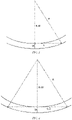
FIG. 3 is a schematic diagram of a conservative method for calculating a safe radius of curvature according to an embodiment of the disclosure; and -
FIG. 4 is a schematic diagram of an aggressive method for calculating a safe radius of curvature according to an embodiment of the disclosure. - To make the objectives, technical solutions, and advantages of the disclosure clearer, specific embodiments of the disclosure will be described in further detail below with reference to the accompanying drawings. It can be understood that the specific embodiments described herein are used merely to explain the disclosure, rather than limit the disclosure.
- In addition, it should also be noted that, for ease of description, the accompanying drawings show only parts related to the disclosure rather than all content of the disclosure. Before discussing exemplary embodiments in more detail, it should be noted that some exemplary embodiments are described as processes or methods that are depicted as flowcharts. Although the flowcharts describe various operations (or steps) as sequential processing, many of the operations may be implemented in parallel, concurrently, or simultaneously. In addition, the sequence of the operations may be rearranged. The processing may be terminated when its operations are completed, but it may also have additional steps not included in the accompanying drawings. The processing may correspond to methods, functions, procedures, subroutines, subprograms, and so on.
- Although exemplary embodiments are described as using a plurality of units to perform exemplary processes, it should be understood that these exemplary processes may also be performed by one or more modules.
- Moreover, control logic of the disclosure may be included on a computer-readable medium as executable program instructions, which are implemented by a processor or the like. Instances of the computer-readable medium include, but are not limited to, a ROM, a RAM, an optical disc, a magnetic tape, a floppy disk, a flash drive, a smart card, and an optical data storage apparatus. A computer-readable recording medium may also be distributed in a computer system connected to a network, so that the computer-readable medium is stored and implemented in a distributed manner, for example, through a vehicle telematics service or a controller area network (CAN).
- Unless specifically mentioned or obvious from context, as used herein, the term "approximately" is understood to be within a range of normal tolerance in the art, for example, within two standard deviations of a mean.
- It should be understood that the term "vehicle" or another similar term used herein includes general motor vehicles, such as passenger vehicles (including sport utility vehicles, buses, trucks, etc.) and various commercial vehicles, and includes hybrid vehicles, electric vehicles, etc. A hybrid vehicle is a vehicle with two or more power sources, such as a vehicle powered by a gasoline engine and an electric motor.
- Control solutions for driver assistance according to various exemplary embodiments of the disclosure will be described below in detail with reference to the accompanying drawings.
-
FIG. 1 is a schematic flowchart of acontrol method 1000 for driver assistance according to an embodiment of the disclosure. As shown inFIG. 1 , thecontrol method 1000 for driver assistance includes the following steps: - step S110 of receiving positioning information of a vehicle;
- step S120 of obtaining information about a road structure ahead of the vehicle based on the positioning information; and
- step S130 of determining, based on the information about the road structure, whether an alarm for a sharp bend is needed.
- In the context of the disclosure, the "positioning information of a vehicle" may also be referred to as position information of the vehicle, where the information is used to signify a real-time position and/or a motion trajectory of the current vehicle. In one or more embodiments, the positioning information of the vehicle may be obtained by using a global positioning system (GPS). In an embodiment, the positioning information of the vehicle includes not only GPS information of the vehicle, and also includes lane navigation information.
- The term "information about a road structure", as the name suggests, is various information for description of the road structure, which, for example, may be obtained from a high-definition map. In one or more embodiments, the information about the road structure includes one or more of the actual radius of curvature of the road, a lane width, lane data, and a lane structure.
- In an embodiment, the obtaining information about a road structure ahead of the vehicle based on the positioning information in
step S 120 may include: searching and obtaining, based on the GPS information of the vehicle and the lane navigation information, road information on a high-definition map within a certain distance (for example, 2 km or 2.5 km, or within the range of other distances) ahead of a moving path in a lane, where the road information includes a road curvature, a lane width, lane data, a lane structure, and other necessary information about the road structure. - In an embodiment, step S130 may include: calculating a safe radius of curvature based on the information about the road structure; and determining, based on the safe radius of curvature, whether the alarm for a sharp bend is needed. In an embodiment, the calculating a safe radius of curvature based on the information about the road structure includes: calculating a minimum value of a safe sight distance on a road; and calculating the safe radius of curvature based on the information about the road structure and the minimum value of the safe sight distance on the road. In an embodiment, the determining, based on the safe radius of curvature, whether the alarm for a sharp bend is needed includes: determining, when an actual radius of curvature of the road is less than the safe radius of curvature, that the alarm for a sharp bend is needed.
- The term "safe radius of curvature" in the context of the disclosure includes not only a safe radius of curvature estimated based on the information about the road structure and the minimum value of the safe sight distance on the road, and also includes a minimum radius of curvature of a circular curve of this section of road that is calculated based on the value of the speed limit on the road and that complies with national laws and regulations.
- In an embodiment, a value of a safe sight distance required for driving on this section of road may be calculated based on the value of the speed limit on the road. Specifically, an estimation may be performed according to the following formula:

- In another embodiment, a value of a safe sight distance required for driving on this section of road may be calculated based on a value of an actual vehicle speed of the present vehicle. For example, an estimation may be performed according to the following formula:

- In an embodiment, in a comparatively conservative solution, it may be required that there still should be a sufficient sight distance for safety when the vehicle travels in the innermost lane on a bend. For example, the safe radius of curvature R may be calculated according to


- It is understood by those skilled in the art that the constants used in the above formula may be calibrated according to engineering requirements. It should also be understood that the above method for calculating the width of the road is merely an example, which is not limited in the disclosure.
- In still another embodiment, the safe radius of curvature R may be calculated according to a formula


- In addition, those skilled in the art readily understand that the
control method 1000 for driver assistance provided in the one or more embodiments of the disclosure may be implemented by a computer program. For example, when a computer storage medium (such as a USB flash drive) storing the computer program is connected to a computer, the control method for driver assistance according to one or more embodiments of the disclosure can be performed by running the computer program. - Referring to
FIG. 2, FIG. 2 is a schematic structural diagram of acontrol device 2000 for driver assistance according to an embodiment of the disclosure. As shown inFIG. 2 , thecontrol device 2000 for driver assistance includes a receivingapparatus 210, an obtainingapparatus 220, and adetermination apparatus 230. The receivingapparatus 210 is configured to receive positioning information of a vehicle; the obtainingapparatus 220 is configured to obtain information about a road structure ahead of the vehicle based on the positioning information; and thedetermination apparatus 230 is configured to determine, based on the information about the road structure, whether an alarm for a sharp bend is needed. - In the context of the disclosure, the "positioning information of a vehicle" may also be referred to as position information of the vehicle, where the information is used to signify a real-time position and/or a motion trajectory of the current vehicle. In one or more embodiments, the positioning information of the vehicle may be obtained by using a global positioning system (GPS). In an embodiment, the positioning information of the vehicle includes not only GPS information of the vehicle, and also includes lane navigation information.
- The term "information about a road structure", as the name suggests, is various information for description of the road structure, which, for example, may be obtained from a high-definition map. In one or more embodiments, the information about the road structure includes one or more of the actual radius of curvature of the road, a lane width, lane data, and a lane structure.
- In an embodiment, in the
above device 2000, the obtainingapparatus 220 may be configured to search and obtain, based on the GPS information of the vehicle and the lane navigation information, road information on a high-definition map within a certain distance (for example, 2 km or 2.5 km, or within the range of other distances) ahead of a moving path in a lane, where the road information includes a road curvature, a lane width, lane data, a lane structure, and other necessary information about the road structure. - In an embodiment, although not shown in
FIG. 2 , thedetermination apparatus 230 includes: a calculation unit configured to calculate a safe radius of curvature based on the information about the road structure; and a determination unit configured to determine, based on the safe radius of curvature, whether the alarm for a sharp bend is needed. In an embodiment, the calculation unit is configured to: calculate a minimum value of a safe sight distance on a road; and calculate the safe radius of curvature based on the information about the road structure and the minimum value of the safe sight distance on the road. In an embodiment, the determination unit is configured to determine, when an actual radius of curvature of the road is less than the safe radius of curvature, that the alarm for a sharp bend is needed. - The term "safe radius of curvature" in the context of the disclosure includes not only a safe radius of curvature estimated based on the information about the road structure and the minimum value of the safe sight distance on the road, and also includes a minimum radius of curvature of a circular curve of this section of road that is calculated based on the value of the speed limit on the road and that complies with national laws and regulations.
- In an embodiment, the calculation unit may be configured to calculate a value of a safe sight distance required for driving on this section of road based on the value of the speed limit on the road. Specifically, the calculation unit may perform an estimation according to the following formula:

- In another embodiment, the calculation unit may be configured to calculate a value of a safe sight distance required for driving on this section of road based on a value of an actual vehicle speed of the present vehicle. For example, the calculation unit may perform an estimation according to the following formula:

- In an embodiment, in a comparatively conservative solution, it may be required that there still should be a sufficient sight distance for safety when the vehicle travels in the innermost lane on a bend. For example, the calculation unit may calculate the safe radius of curvature R according to


- It is understood by those skilled in the art that the constants used in the above formula may be calibrated according to engineering requirements. It should also be understood that the above method for calculating the width of the road is merely an example, which is not limited in the disclosure.
- In still another embodiment, the calculation unit may calculate the safe radius of curvature R according to a formula


- In one or more embodiments, the
control device 2000 for driver assistance may be integrated in ADAS systems. ADAS systems may also be referred to as advanced driver assistance systems. The advanced driver assistance systems use a variety of sensors (such as a millimeter-wave radar, a laser radar, a monocular/binocular camera, and satellite navigation) mounted on an automobile to sense the surrounding environment at any time during traveling of the automobile, collect data, identify, monitor, and track a still/moving object, and perform system operations and analysis in combination with navigation map data, allowing for a driver to be aware of potential dangers in advance, thereby effectively improving the comfort and safety of the automobile during traveling. In an embodiment, the advanced driver assistance systems include a traffic message channel (TMC) system, an intelligent speed adaptation or intelligent speed advice (ISA) system, a vehicular communication system, an adaptive cruise control (ACC) system, a lane departure warning system (LDWS), a lane keeping assistance system, a collision avoidance system or a pre-crash system, a night vision system, an adaptive light control system, a pedestrian protection system, an automatic parking system, a traffic sign recognition system, a blind spot detection system, a driver drowsiness detection system, a hill descent control system, and an electric vehicle warning sounds system. - In one or more embodiments, the
control device 2000 for driver assistance is included in a controller of ADAS. Various control operations within thecontrol device 2000 for driver assistance may be performed periodically, and a performance period may be dependent on an operation period of the controller of ADAS. During each performance, in an embodiment, road information within a given distance (that may be calibrated as needed) ahead of the vehicle may be traversed, and a minimum value of a safe sight distance on a road is then estimated. - Upon obtaining of the minimum value of the safe sight distance on the road, a required safe radius of curvature may be further estimated based on information about a road structure. For example, in a conservative solution, it may be required that there still should be a sufficient sight distance for safety when the vehicle travels in the innermost lane on a bend. For example, referring to
FIG. 3 , the radius of curvature of the road is calculated according to the following formula: (R - W)2 + L2 = R2. It can be learned that a conservative estimation of a safe radius of curvature of the road based on a speed limit on the road is:
- In addition, a conservative estimation of a safe radius of curvature of the road based on a real-time vehicle speed is:

- For another example, in an aggressive solution, it may be required that there still should be a sufficient sight distance for safety when the vehicle travels in the outermost lane on a bend. For example, referring to
FIG. 4 , the radius of curvature of the road is calculated according to the following formula: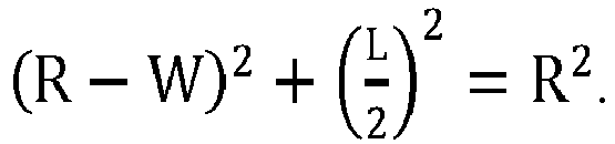
- It can be learned that an aggressive estimation of a safe radius of curvature of the road based on a speed limit on the road is:

- In addition, an aggressive estimation of a safe radius of curvature of the road based on a real-time vehicle speed is:

- It should be noted that the "safe radius of curvature" in the context of the disclosure may be estimated not only based on information about the road structure and the minimum value of the safe sight distance on the road, and may also be calculated based on the value of the speed limit on the road. In an embodiment, a minimum safe radius of curvature of the road may be calculated according to the following formula:


- In the above embodiment, different warning or alarm conditions may be selected according to different situations. For example, upon selection of a conservative warning condition, a warning may be sent when any one of the inequation 1, the
inequation 2, and the inequation 5 cannot be satisfied. For another example, upon selection of an aggressive warning condition, a warning may be sent when any one of the inequation 3, the inequation 4, and the inequation 5 cannot be satisfied. - In conclusion, in the control solution for driver assistance according to the embodiments of the disclosure, the positioning information of the vehicle is received, and the information about the road structure ahead of the vehicle is obtained based on the positioning information, such that it can be determined whether the alarm for a sharp bend is needed. The solution fills the gaps in dealing with sharp bends in the field of autonomous driving, and can allow for effective pre-warning of an environment with a sharp bend (and/or corresponding control of deceleration), thereby greatly reducing the accident rates on roads with sharp bends and improving driving safety.
- Although only some embodiments of the disclosure are described in the specification, it will be appreciated by those skilled in the art that the disclosure may be embodied in many other forms without departing from the essence and scope thereof. Accordingly, the presented examples and implementations are considered to be illustrative rather than restrictive, and the disclosure may encompass various modifications and substitutions without departing from the spirit and scope of the disclosure that are defined by the appended claims.
Claims (9)
- A control method for driver assistance, comprising:receiving positioning information of a vehicle;obtaining information about a road structure ahead of the vehicle based on the positioning information; anddetermining, based on the information about the road structure, whether an alarm for a sharp bend is needed.
- The method according to claim 1, wherein the determining, based on the information about the road structure, whether an alarm for a sharp bend is needed comprises:calculating a safe radius of curvature based on the information about the road structure; anddetermining, based on the safe radius of curvature, whether the alarm for a sharp bend is needed.
- The method according to claim 2, wherein the calculating a safe radius of curvature based on the information about the road structure comprises:calculating a minimum value of a safe sight distance on a road; andcalculating the safe radius of curvature based on the information about the road structure and the minimum value of the safe sight distance on the road.
- The method according to claim 3, wherein the calculating a minimum value of a safe sight distance on a road comprises:
calculating the minimum value of the safe sight distance on the road based on a value of a speed limit on the road or an actual vehicle speed of a current vehicle. - A control device for driver assistance, comprising:a receiving apparatus configured to receive positioning information of a vehicle;an obtaining apparatus configured to obtain information about a road structure ahead of the vehicle based on the positioning information; anda determination apparatus configured to determine, based on the information about the road structure, whether an alarm for a sharp bend is needed.
- The device according to claim 5, wherein the determination apparatus comprises:a calculation unit configured to calculate a safe radius of curvature based on the information about the road structure; anda determination unit configured to determine, based on the safe radius of curvature, whether the alarm for a sharp bend is needed.
- The device according to claim 6, wherein the calculation unit is configured to:calculate a minimum value of a safe sight distance on a road; andcalculate the safe radius of curvature based on the information about the road structure and the minimum value of the safe sight distance on the road.
- The device according to claim 7, wherein the calculation unit is configured to:
calculate the minimum value of the safe sight distance on the road based on a value of a speed limit on the road or an actual vehicle speed of a current vehicle. - A computer storage medium, comprising instructions, wherein when the instructions are run, a control method for driver assistance is performed, preferably the method of any one of claims 1 to 4, the method comprising:receiving positioning information of a vehicle;obtaining information about a road structure ahead of the vehicle based on the positioning information; anddetermining, based on the information about the road structure, whether an alarm for a sharp bend is needed.
Applications Claiming Priority (1)
| Application Number | Priority Date | Filing Date | Title |
|---|---|---|---|
| CN202110702159.8A CN113212436A (en) | 2021-06-23 | 2021-06-23 | Driving assistance control method and device |
Publications (2)
| Publication Number | Publication Date |
|---|---|
| EP4108536A1 true EP4108536A1 (en) | 2022-12-28 |
| EP4108536B1 EP4108536B1 (en) | 2025-03-12 |
Family
ID=77081120
Family Applications (1)
| Application Number | Title | Priority Date | Filing Date |
|---|---|---|---|
| EP22165735.6A Active EP4108536B1 (en) | 2021-06-23 | 2022-03-31 | Control method and device for driver assistance |
Country Status (3)
| Country | Link |
|---|---|
| US (1) | US11801857B2 (en) |
| EP (1) | EP4108536B1 (en) |
| CN (1) | CN113212436A (en) |
Citations (2)
| Publication number | Priority date | Publication date | Assignee | Title |
|---|---|---|---|---|
| US20170066450A1 (en) * | 2015-09-08 | 2017-03-09 | Thinkware Corporation | Curve guidance method, curve guidance apparatus, electronic apparatus and program stored in the computer-readable recording medium |
| DE102019202581A1 (en) * | 2019-02-26 | 2020-08-27 | Volkswagen Aktiengesellschaft | Method for operating a driver information system in an ego vehicle and driver information system |
Family Cites Families (18)
| Publication number | Priority date | Publication date | Assignee | Title |
|---|---|---|---|---|
| DE19940723A1 (en) * | 1999-08-27 | 2001-03-08 | Daimler Chrysler Ag | Method for displaying a perspective image and display device for at least one occupant of a vehicle |
| JP3838613B2 (en) * | 1999-08-31 | 2006-10-25 | 本田技研工業株式会社 | In-vehicle display device |
| US6864784B1 (en) * | 2002-07-19 | 2005-03-08 | Barry Loeb | Vehicle speed and safety warning system |
| DE10311241B4 (en) * | 2003-03-14 | 2021-05-27 | Robert Bosch Gmbh | Method and device for tracking a vehicle |
| WO2005080120A1 (en) * | 2004-02-20 | 2005-09-01 | Sharp Kabushiki Kaisha | Condition detection and display system, condition detection and display method, control program for condition detection and display system, and storage medium storing the control program |
| JP4453468B2 (en) * | 2004-07-16 | 2010-04-21 | 日産自動車株式会社 | Preceding vehicle following travel control device |
| JP2006112962A (en) * | 2004-10-15 | 2006-04-27 | Aisin Aw Co Ltd | Method and apparatus for supporting driving operation |
| DE602004016348D1 (en) * | 2004-11-19 | 2008-10-16 | Harman Becker Automotive Sys | Vehicle navigation with integrated cornering warning is based on clothoids |
| DE102008012654A1 (en) * | 2007-08-29 | 2009-03-05 | Continental Teves Ag & Co. Ohg | Online creation of a digital map |
| JP5510254B2 (en) * | 2010-10-01 | 2014-06-04 | トヨタ自動車株式会社 | Driving support apparatus and method |
| JP5997437B2 (en) * | 2011-12-06 | 2016-09-28 | 矢崎エナジーシステム株式会社 | Driving assistance device |
| DE102012002149B3 (en) * | 2012-02-04 | 2013-06-20 | Audi Ag | Method for visualizing the environment of a motor vehicle and associated motor vehicle |
| US8872363B2 (en) * | 2012-05-11 | 2014-10-28 | Bader Abdullah ALMALKI | Vehicle movement activated electrical power generator, and method for providing electrical power for roadside applications |
| JP6870447B2 (en) * | 2016-05-20 | 2021-05-12 | 株式会社リコー | HUD device, vehicle device, information display method. |
| JP2018077612A (en) * | 2016-11-08 | 2018-05-17 | 三菱自動車工業株式会社 | Driving assistance device |
| CN108572650B (en) * | 2018-05-08 | 2021-08-24 | 南京信息工程大学 | An Adaptive Headlight Steering Control Algorithm Based on Lane Line Detection |
| CN109624842B (en) * | 2019-01-23 | 2021-03-09 | 浙江吉利汽车研究院有限公司 | A kind of control method and device for automatic whistle of automobile |
| CN112572437B (en) * | 2020-12-18 | 2022-09-30 | 北京京东乾石科技有限公司 | Method, device and equipment for determining driving direction and storage medium |
-
2021
- 2021-06-23 CN CN202110702159.8A patent/CN113212436A/en active Pending
-
2022
- 2022-03-31 EP EP22165735.6A patent/EP4108536B1/en active Active
- 2022-06-14 US US17/839,777 patent/US11801857B2/en active Active
Patent Citations (2)
| Publication number | Priority date | Publication date | Assignee | Title |
|---|---|---|---|---|
| US20170066450A1 (en) * | 2015-09-08 | 2017-03-09 | Thinkware Corporation | Curve guidance method, curve guidance apparatus, electronic apparatus and program stored in the computer-readable recording medium |
| DE102019202581A1 (en) * | 2019-02-26 | 2020-08-27 | Volkswagen Aktiengesellschaft | Method for operating a driver information system in an ego vehicle and driver information system |
Also Published As
| Publication number | Publication date |
|---|---|
| US20220410919A1 (en) | 2022-12-29 |
| CN113212436A (en) | 2021-08-06 |
| EP4108536B1 (en) | 2025-03-12 |
| US11801857B2 (en) | 2023-10-31 |
Similar Documents
| Publication | Publication Date | Title |
|---|---|---|
| EP4074565A1 (en) | Automated lane changing device and method for vehicle | |
| CN111775940B (en) | Automatic channel changing method, device, equipment and storage medium | |
| US8660778B2 (en) | Running plan creating apparatus | |
| US12236788B2 (en) | Method and device for lane-changing prediction of target vehicle | |
| EP1087358B1 (en) | Curve approaching mode controller | |
| US11518380B2 (en) | System and method for predicted vehicle incident warning and evasion | |
| US20140257686A1 (en) | Vehicle lane determination | |
| JP6532593B2 (en) | Reverse run suppression device, reverse run suppression method and reverse run suppression system | |
| EP3045868B1 (en) | Route selection and automatic driving device | |
| EP4316935A1 (en) | Method and apparatus for obtaining lane change area | |
| JP2010066827A (en) | Driving support system, driving support device and driving support method | |
| EP3552905B1 (en) | Vehicle apparatus, system having the same and method for automatically changing operable range thereof | |
| EP4125061A1 (en) | Road model generation method and device | |
| US20210163009A1 (en) | Method and device for assisting a driver in a vehicle | |
| US20200307598A1 (en) | Traveling control apparatus, traveling control method, and non-transitory computer-readable storage medium storing program | |
| CN114475619A (en) | Automobile control method and device and computer storage medium | |
| CN116238483A (en) | A method and system for quantifying the driving risk of one's own vehicle considering the collision between one's own vehicle and another vehicle | |
| CN118618417A (en) | A method and system for automatic driving safety protection | |
| US20250206339A1 (en) | Autonomous driving vehicles and methods for controlling the same | |
| US11801857B2 (en) | Control method and device for driver assistance | |
| EP4125051A1 (en) | Method and device for determining reliability of visual detection | |
| EP4325462B1 (en) | Method for detecting a wide turn maneuver of a vehicle, method for operating an ego-vehicle, data processing apparatus, computer program, and computer-readable storage medium | |
| CN117953609A (en) | Method, device, equipment and medium for processing accident data of autonomous driving vehicle | |
| JP7694117B2 (en) | Traffic Safety Systems | |
| CN112721925A (en) | Intelligent driving system |
Legal Events
| Date | Code | Title | Description |
|---|---|---|---|
| PUAI | Public reference made under article 153(3) epc to a published international application that has entered the european phase |
Free format text: ORIGINAL CODE: 0009012 |
|
| STAA | Information on the status of an ep patent application or granted ep patent |
Free format text: STATUS: REQUEST FOR EXAMINATION WAS MADE |
|
| 17P | Request for examination filed |
Effective date: 20220331 |
|
| AK | Designated contracting states |
Kind code of ref document: A1 Designated state(s): AL AT BE BG CH CY CZ DE DK EE ES FI FR GB GR HR HU IE IS IT LI LT LU LV MC MK MT NL NO PL PT RO RS SE SI SK SM TR |
|
| GRAP | Despatch of communication of intention to grant a patent |
Free format text: ORIGINAL CODE: EPIDOSNIGR1 |
|
| STAA | Information on the status of an ep patent application or granted ep patent |
Free format text: STATUS: GRANT OF PATENT IS INTENDED |
|
| RIC1 | Information provided on ipc code assigned before grant |
Ipc: B60W 50/14 20200101AFI20241015BHEP |
|
| INTG | Intention to grant announced |
Effective date: 20241114 |
|
| GRAS | Grant fee paid |
Free format text: ORIGINAL CODE: EPIDOSNIGR3 |
|
| GRAA | (expected) grant |
Free format text: ORIGINAL CODE: 0009210 |
|
| STAA | Information on the status of an ep patent application or granted ep patent |
Free format text: STATUS: THE PATENT HAS BEEN GRANTED |
|
| AK | Designated contracting states |
Kind code of ref document: B1 Designated state(s): AL AT BE BG CH CY CZ DE DK EE ES FI FR GB GR HR HU IE IS IT LI LT LU LV MC MK MT NL NO PL PT RO RS SE SI SK SM TR |
|
| REG | Reference to a national code |
Ref country code: GB Ref legal event code: FG4D |
|
| REG | Reference to a national code |
Ref country code: CH Ref legal event code: EP |
|
| REG | Reference to a national code |
Ref country code: DE Ref legal event code: R096 Ref document number: 602022011586 Country of ref document: DE |
|
| REG | Reference to a national code |
Ref country code: IE Ref legal event code: FG4D |
|
| PG25 | Lapsed in a contracting state [announced via postgrant information from national office to epo] |
Ref country code: RS Free format text: LAPSE BECAUSE OF FAILURE TO SUBMIT A TRANSLATION OF THE DESCRIPTION OR TO PAY THE FEE WITHIN THE PRESCRIBED TIME-LIMIT Effective date: 20250612 |
|
| PG25 | Lapsed in a contracting state [announced via postgrant information from national office to epo] |
Ref country code: FI Free format text: LAPSE BECAUSE OF FAILURE TO SUBMIT A TRANSLATION OF THE DESCRIPTION OR TO PAY THE FEE WITHIN THE PRESCRIBED TIME-LIMIT Effective date: 20250312 |
|
| PG25 | Lapsed in a contracting state [announced via postgrant information from national office to epo] |
Ref country code: ES Free format text: LAPSE BECAUSE OF FAILURE TO SUBMIT A TRANSLATION OF THE DESCRIPTION OR TO PAY THE FEE WITHIN THE PRESCRIBED TIME-LIMIT Effective date: 20250312 |
|
| REG | Reference to a national code |
Ref country code: LT Ref legal event code: MG9D |
|
| PG25 | Lapsed in a contracting state [announced via postgrant information from national office to epo] |
Ref country code: NO Free format text: LAPSE BECAUSE OF FAILURE TO SUBMIT A TRANSLATION OF THE DESCRIPTION OR TO PAY THE FEE WITHIN THE PRESCRIBED TIME-LIMIT Effective date: 20250612 |
|
| PG25 | Lapsed in a contracting state [announced via postgrant information from national office to epo] |
Ref country code: HR Free format text: LAPSE BECAUSE OF FAILURE TO SUBMIT A TRANSLATION OF THE DESCRIPTION OR TO PAY THE FEE WITHIN THE PRESCRIBED TIME-LIMIT Effective date: 20250312 |
|
| REG | Reference to a national code |
Ref country code: NL Ref legal event code: MP Effective date: 20250312 |
|
| PG25 | Lapsed in a contracting state [announced via postgrant information from national office to epo] |
Ref country code: LV Free format text: LAPSE BECAUSE OF FAILURE TO SUBMIT A TRANSLATION OF THE DESCRIPTION OR TO PAY THE FEE WITHIN THE PRESCRIBED TIME-LIMIT Effective date: 20250312 |
|
| PG25 | Lapsed in a contracting state [announced via postgrant information from national office to epo] |
Ref country code: BG Free format text: LAPSE BECAUSE OF FAILURE TO SUBMIT A TRANSLATION OF THE DESCRIPTION OR TO PAY THE FEE WITHIN THE PRESCRIBED TIME-LIMIT Effective date: 20250312 Ref country code: GR Free format text: LAPSE BECAUSE OF FAILURE TO SUBMIT A TRANSLATION OF THE DESCRIPTION OR TO PAY THE FEE WITHIN THE PRESCRIBED TIME-LIMIT Effective date: 20250613 |
|
| REG | Reference to a national code |
Ref country code: AT Ref legal event code: MK05 Ref document number: 1774807 Country of ref document: AT Kind code of ref document: T Effective date: 20250312 |
|
| PG25 | Lapsed in a contracting state [announced via postgrant information from national office to epo] |
Ref country code: NL Free format text: LAPSE BECAUSE OF FAILURE TO SUBMIT A TRANSLATION OF THE DESCRIPTION OR TO PAY THE FEE WITHIN THE PRESCRIBED TIME-LIMIT Effective date: 20250312 |
|
| PG25 | Lapsed in a contracting state [announced via postgrant information from national office to epo] |
Ref country code: SE Free format text: LAPSE BECAUSE OF FAILURE TO SUBMIT A TRANSLATION OF THE DESCRIPTION OR TO PAY THE FEE WITHIN THE PRESCRIBED TIME-LIMIT Effective date: 20250312 |
|
| PG25 | Lapsed in a contracting state [announced via postgrant information from national office to epo] |
Ref country code: SM Free format text: LAPSE BECAUSE OF FAILURE TO SUBMIT A TRANSLATION OF THE DESCRIPTION OR TO PAY THE FEE WITHIN THE PRESCRIBED TIME-LIMIT Effective date: 20250312 |
|
| PG25 | Lapsed in a contracting state [announced via postgrant information from national office to epo] |
Ref country code: PT Free format text: LAPSE BECAUSE OF FAILURE TO SUBMIT A TRANSLATION OF THE DESCRIPTION OR TO PAY THE FEE WITHIN THE PRESCRIBED TIME-LIMIT Effective date: 20250714 |
|
| PG25 | Lapsed in a contracting state [announced via postgrant information from national office to epo] |
Ref country code: IT Free format text: LAPSE BECAUSE OF FAILURE TO SUBMIT A TRANSLATION OF THE DESCRIPTION OR TO PAY THE FEE WITHIN THE PRESCRIBED TIME-LIMIT Effective date: 20250312 Ref country code: PL Free format text: LAPSE BECAUSE OF FAILURE TO SUBMIT A TRANSLATION OF THE DESCRIPTION OR TO PAY THE FEE WITHIN THE PRESCRIBED TIME-LIMIT Effective date: 20250312 |
|
| PG25 | Lapsed in a contracting state [announced via postgrant information from national office to epo] |
Ref country code: AT Free format text: LAPSE BECAUSE OF FAILURE TO SUBMIT A TRANSLATION OF THE DESCRIPTION OR TO PAY THE FEE WITHIN THE PRESCRIBED TIME-LIMIT Effective date: 20250312 |
|
| PG25 | Lapsed in a contracting state [announced via postgrant information from national office to epo] |
Ref country code: EE Free format text: LAPSE BECAUSE OF FAILURE TO SUBMIT A TRANSLATION OF THE DESCRIPTION OR TO PAY THE FEE WITHIN THE PRESCRIBED TIME-LIMIT Effective date: 20250312 Ref country code: CZ Free format text: LAPSE BECAUSE OF FAILURE TO SUBMIT A TRANSLATION OF THE DESCRIPTION OR TO PAY THE FEE WITHIN THE PRESCRIBED TIME-LIMIT Effective date: 20250312 |
|
| REG | Reference to a national code |
Ref country code: CH Ref legal event code: H13 Free format text: ST27 STATUS EVENT CODE: U-0-0-H10-H13 (AS PROVIDED BY THE NATIONAL OFFICE) Effective date: 20251023 |
|
| PG25 | Lapsed in a contracting state [announced via postgrant information from national office to epo] |
Ref country code: RO Free format text: LAPSE BECAUSE OF FAILURE TO SUBMIT A TRANSLATION OF THE DESCRIPTION OR TO PAY THE FEE WITHIN THE PRESCRIBED TIME-LIMIT Effective date: 20250312 |
|
| PG25 | Lapsed in a contracting state [announced via postgrant information from national office to epo] |
Ref country code: SK Free format text: LAPSE BECAUSE OF FAILURE TO SUBMIT A TRANSLATION OF THE DESCRIPTION OR TO PAY THE FEE WITHIN THE PRESCRIBED TIME-LIMIT Effective date: 20250312 |
|
| PG25 | Lapsed in a contracting state [announced via postgrant information from national office to epo] |
Ref country code: IS Free format text: LAPSE BECAUSE OF FAILURE TO SUBMIT A TRANSLATION OF THE DESCRIPTION OR TO PAY THE FEE WITHIN THE PRESCRIBED TIME-LIMIT Effective date: 20250712 |
|
| PG25 | Lapsed in a contracting state [announced via postgrant information from national office to epo] |
Ref country code: LU Free format text: LAPSE BECAUSE OF NON-PAYMENT OF DUE FEES Effective date: 20250331 |
|
| REG | Reference to a national code |
Ref country code: BE Ref legal event code: MM Effective date: 20250331 |
|
| REG | Reference to a national code |
Ref country code: DE Ref legal event code: R097 Ref document number: 602022011586 Country of ref document: DE |
|
| PG25 | Lapsed in a contracting state [announced via postgrant information from national office to epo] |
Ref country code: MC Free format text: LAPSE BECAUSE OF FAILURE TO SUBMIT A TRANSLATION OF THE DESCRIPTION OR TO PAY THE FEE WITHIN THE PRESCRIBED TIME-LIMIT Effective date: 20250312 |
|
| PG25 | Lapsed in a contracting state [announced via postgrant information from national office to epo] |
Ref country code: DK Free format text: LAPSE BECAUSE OF FAILURE TO SUBMIT A TRANSLATION OF THE DESCRIPTION OR TO PAY THE FEE WITHIN THE PRESCRIBED TIME-LIMIT Effective date: 20250312 |
|
| PG25 | Lapsed in a contracting state [announced via postgrant information from national office to epo] |
Ref country code: BE Free format text: LAPSE BECAUSE OF NON-PAYMENT OF DUE FEES Effective date: 20250331 |
|
| PLBE | No opposition filed within time limit |
Free format text: ORIGINAL CODE: 0009261 |
|
| STAA | Information on the status of an ep patent application or granted ep patent |
Free format text: STATUS: NO OPPOSITION FILED WITHIN TIME LIMIT |
|
| PG25 | Lapsed in a contracting state [announced via postgrant information from national office to epo] |
Ref country code: CH Free format text: LAPSE BECAUSE OF NON-PAYMENT OF DUE FEES Effective date: 20250331 |
|
| PG25 | Lapsed in a contracting state [announced via postgrant information from national office to epo] |
Ref country code: IE Free format text: LAPSE BECAUSE OF NON-PAYMENT OF DUE FEES Effective date: 20250331 |
|
| REG | Reference to a national code |
Ref country code: CH Ref legal event code: L10 Free format text: ST27 STATUS EVENT CODE: U-0-0-L10-L00 (AS PROVIDED BY THE NATIONAL OFFICE) Effective date: 20260121 |
|
| 26N | No opposition filed |
Effective date: 20251215 |
|
| PGFP | Annual fee paid to national office [announced via postgrant information from national office to epo] |
Ref country code: GB Payment date: 20260324 Year of fee payment: 5 |
|
| PGFP | Annual fee paid to national office [announced via postgrant information from national office to epo] |
Ref country code: DE Payment date: 20260319 Year of fee payment: 5 |
|
| PGFP | Annual fee paid to national office [announced via postgrant information from national office to epo] |
Ref country code: FR Payment date: 20260323 Year of fee payment: 5 |