EP4108490B1 - Powertrain and electric vehicle - Google Patents
Powertrain and electric vehicle Download PDFInfo
- Publication number
- EP4108490B1 EP4108490B1 EP22180316.6A EP22180316A EP4108490B1 EP 4108490 B1 EP4108490 B1 EP 4108490B1 EP 22180316 A EP22180316 A EP 22180316A EP 4108490 B1 EP4108490 B1 EP 4108490B1
- Authority
- EP
- European Patent Office
- Prior art keywords
- oil
- motor
- electronic
- reducer
- cooling
- Prior art date
- Legal status (The legal status is an assumption and is not a legal conclusion. Google has not performed a legal analysis and makes no representation as to the accuracy of the status listed.)
- Active
Links
Images


Classifications
-
- H—ELECTRICITY
- H02—GENERATION; CONVERSION OR DISTRIBUTION OF ELECTRIC POWER
- H02K—DYNAMO-ELECTRIC MACHINES
- H02K7/00—Arrangements for handling mechanical energy structurally associated with dynamo-electric machines, e.g. structural association with mechanical driving motors or auxiliary dynamo-electric machines
- H02K7/10—Structural association with clutches, brakes, gears, pulleys or mechanical starters
-
- H—ELECTRICITY
- H02—GENERATION; CONVERSION OR DISTRIBUTION OF ELECTRIC POWER
- H02K—DYNAMO-ELECTRIC MACHINES
- H02K9/00—Arrangements for cooling or ventilating
- H02K9/19—Arrangements for cooling or ventilating for machines with closed casing and closed-circuit cooling using a liquid cooling medium, e.g. oil
- H02K9/193—Arrangements for cooling or ventilating for machines with closed casing and closed-circuit cooling using a liquid cooling medium, e.g. oil with provision for replenishing the cooling medium; with means for preventing leakage of the cooling medium
-
- B—PERFORMING OPERATIONS; TRANSPORTING
- B60—VEHICLES IN GENERAL
- B60K—ARRANGEMENT OR MOUNTING OF PROPULSION UNITS OR OF TRANSMISSIONS IN VEHICLES; ARRANGEMENT OR MOUNTING OF PLURAL DIVERSE PRIME-MOVERS IN VEHICLES; AUXILIARY DRIVES FOR VEHICLES; INSTRUMENTATION OR DASHBOARDS FOR VEHICLES; ARRANGEMENTS IN CONNECTION WITH COOLING, AIR INTAKE, GAS EXHAUST OR FUEL SUPPLY OF PROPULSION UNITS IN VEHICLES
- B60K1/00—Arrangement or mounting of electrical propulsion units
- B60K1/02—Arrangement or mounting of electrical propulsion units comprising more than one electric motor
-
- B—PERFORMING OPERATIONS; TRANSPORTING
- B60—VEHICLES IN GENERAL
- B60K—ARRANGEMENT OR MOUNTING OF PROPULSION UNITS OR OF TRANSMISSIONS IN VEHICLES; ARRANGEMENT OR MOUNTING OF PLURAL DIVERSE PRIME-MOVERS IN VEHICLES; AUXILIARY DRIVES FOR VEHICLES; INSTRUMENTATION OR DASHBOARDS FOR VEHICLES; ARRANGEMENTS IN CONNECTION WITH COOLING, AIR INTAKE, GAS EXHAUST OR FUEL SUPPLY OF PROPULSION UNITS IN VEHICLES
- B60K11/00—Arrangement in connection with cooling of propulsion units
- B60K11/02—Arrangement in connection with cooling of propulsion units with liquid cooling
-
- B—PERFORMING OPERATIONS; TRANSPORTING
- B60—VEHICLES IN GENERAL
- B60K—ARRANGEMENT OR MOUNTING OF PROPULSION UNITS OR OF TRANSMISSIONS IN VEHICLES; ARRANGEMENT OR MOUNTING OF PLURAL DIVERSE PRIME-MOVERS IN VEHICLES; AUXILIARY DRIVES FOR VEHICLES; INSTRUMENTATION OR DASHBOARDS FOR VEHICLES; ARRANGEMENTS IN CONNECTION WITH COOLING, AIR INTAKE, GAS EXHAUST OR FUEL SUPPLY OF PROPULSION UNITS IN VEHICLES
- B60K17/00—Arrangement or mounting of transmissions in vehicles
- B60K17/04—Arrangement or mounting of transmissions in vehicles characterised by arrangement, location or kind of gearing
- B60K17/043—Transmission unit disposed in on near the vehicle wheel, or between the differential gear unit and the wheel
-
- B—PERFORMING OPERATIONS; TRANSPORTING
- B60—VEHICLES IN GENERAL
- B60K—ARRANGEMENT OR MOUNTING OF PROPULSION UNITS OR OF TRANSMISSIONS IN VEHICLES; ARRANGEMENT OR MOUNTING OF PLURAL DIVERSE PRIME-MOVERS IN VEHICLES; AUXILIARY DRIVES FOR VEHICLES; INSTRUMENTATION OR DASHBOARDS FOR VEHICLES; ARRANGEMENTS IN CONNECTION WITH COOLING, AIR INTAKE, GAS EXHAUST OR FUEL SUPPLY OF PROPULSION UNITS IN VEHICLES
- B60K7/00—Disposition of motor in, or adjacent to, traction wheel
- B60K7/0007—Disposition of motor in, or adjacent to, traction wheel the motor being electric
-
- B—PERFORMING OPERATIONS; TRANSPORTING
- B60—VEHICLES IN GENERAL
- B60K—ARRANGEMENT OR MOUNTING OF PROPULSION UNITS OR OF TRANSMISSIONS IN VEHICLES; ARRANGEMENT OR MOUNTING OF PLURAL DIVERSE PRIME-MOVERS IN VEHICLES; AUXILIARY DRIVES FOR VEHICLES; INSTRUMENTATION OR DASHBOARDS FOR VEHICLES; ARRANGEMENTS IN CONNECTION WITH COOLING, AIR INTAKE, GAS EXHAUST OR FUEL SUPPLY OF PROPULSION UNITS IN VEHICLES
- B60K1/00—Arrangement or mounting of electrical propulsion units
-
- B—PERFORMING OPERATIONS; TRANSPORTING
- B60—VEHICLES IN GENERAL
- B60K—ARRANGEMENT OR MOUNTING OF PROPULSION UNITS OR OF TRANSMISSIONS IN VEHICLES; ARRANGEMENT OR MOUNTING OF PLURAL DIVERSE PRIME-MOVERS IN VEHICLES; AUXILIARY DRIVES FOR VEHICLES; INSTRUMENTATION OR DASHBOARDS FOR VEHICLES; ARRANGEMENTS IN CONNECTION WITH COOLING, AIR INTAKE, GAS EXHAUST OR FUEL SUPPLY OF PROPULSION UNITS IN VEHICLES
- B60K11/00—Arrangement in connection with cooling of propulsion units
- B60K11/02—Arrangement in connection with cooling of propulsion units with liquid cooling
- B60K11/04—Arrangement or mounting of radiators, radiator shutters, or radiator blinds
-
- B—PERFORMING OPERATIONS; TRANSPORTING
- B60—VEHICLES IN GENERAL
- B60K—ARRANGEMENT OR MOUNTING OF PROPULSION UNITS OR OF TRANSMISSIONS IN VEHICLES; ARRANGEMENT OR MOUNTING OF PLURAL DIVERSE PRIME-MOVERS IN VEHICLES; AUXILIARY DRIVES FOR VEHICLES; INSTRUMENTATION OR DASHBOARDS FOR VEHICLES; ARRANGEMENTS IN CONNECTION WITH COOLING, AIR INTAKE, GAS EXHAUST OR FUEL SUPPLY OF PROPULSION UNITS IN VEHICLES
- B60K1/00—Arrangement or mounting of electrical propulsion units
- B60K2001/003—Arrangement or mounting of electrical propulsion units with means for cooling the electrical propulsion units
- B60K2001/006—Arrangement or mounting of electrical propulsion units with means for cooling the electrical propulsion units the electric motors
-
- B—PERFORMING OPERATIONS; TRANSPORTING
- B60—VEHICLES IN GENERAL
- B60K—ARRANGEMENT OR MOUNTING OF PROPULSION UNITS OR OF TRANSMISSIONS IN VEHICLES; ARRANGEMENT OR MOUNTING OF PLURAL DIVERSE PRIME-MOVERS IN VEHICLES; AUXILIARY DRIVES FOR VEHICLES; INSTRUMENTATION OR DASHBOARDS FOR VEHICLES; ARRANGEMENTS IN CONNECTION WITH COOLING, AIR INTAKE, GAS EXHAUST OR FUEL SUPPLY OF PROPULSION UNITS IN VEHICLES
- B60K7/00—Disposition of motor in, or adjacent to, traction wheel
- B60K2007/0046—Disposition of motor in, or adjacent to, traction wheel the motor moving together with the vehicle body, i.e. moving independently from the wheel axle
-
- B—PERFORMING OPERATIONS; TRANSPORTING
- B60—VEHICLES IN GENERAL
- B60Y—INDEXING SCHEME RELATING TO ASPECTS CROSS-CUTTING VEHICLE TECHNOLOGY
- B60Y2410/00—Constructional features of vehicle sub-units
- B60Y2410/10—Housings
-
- Y—GENERAL TAGGING OF NEW TECHNOLOGICAL DEVELOPMENTS; GENERAL TAGGING OF CROSS-SECTIONAL TECHNOLOGIES SPANNING OVER SEVERAL SECTIONS OF THE IPC; TECHNICAL SUBJECTS COVERED BY FORMER USPC CROSS-REFERENCE ART COLLECTIONS [XRACs] AND DIGESTS
- Y02—TECHNOLOGIES OR APPLICATIONS FOR MITIGATION OR ADAPTATION AGAINST CLIMATE CHANGE
- Y02T—CLIMATE CHANGE MITIGATION TECHNOLOGIES RELATED TO TRANSPORTATION
- Y02T10/00—Road transport of goods or passengers
- Y02T10/60—Other road transportation technologies with climate change mitigation effect
- Y02T10/64—Electric machine technologies in electromobility
Definitions
- This invention relates to the field of motor cooling technologies, and in particular, to a powertrain and an electric vehicle.
- a powertrain of an electric vehicle includes a motor and a reducer.
- the motor is configured to convert electric energy supplied by a power battery pack of the electric vehicle into mechanical energy.
- the reducer is configured to transmit the mechanical energy generated by the motor to a wheel of the electric vehicle, so as to drive the electric vehicle to run.
- the reducer mainly includes components such as a gear, a bearing, and a housing.
- cooling oil is mainly driven by an electric oil pump to circulate heat between the inside of the powertrain and a heat exchanger for lubrication and cooling.
- a motor cooling effect depends on performance of the electric oil pump and the heat exchanger.
- miniaturization of a motor leads to a smaller oil passage for cooling oil to circulate in the motor.
- flow resistance of the cooling oil flowing in the oil passage is increased and a flow rate is decreased, thereby reducing a cooling effect of the cooling oil for the motor, that is, a cooling effect of a cooling system for the powertrain is poor.
- the document US 2021/0039491 A1 shows a drive unit for an electric vehicle. A motor and a reducer are supplied by cooling oil from an oil pan, by a single oil pump.
- the document DE 10 2018 121 203 A1 shows a cooling unit for an electrical motor.
- the electrical motor comprises two independent cooling circuits, which are supplied with cooling oil by two independent oil pumps.
- the document EP 3 517 745 A1 shows a vehicle drive system comprising an electrical motor and two oil pumps. The two oil pumps, connected to different parts of the motor.
- this invention provides a powertrain and an electric vehicle, to improve a cooling effect of a cooling system for the powertrain.
- the present invention is defined by the independent claims. Further advantageous developments are shown by the dependent claims.
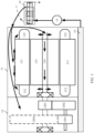
- FIG. 1 is a schematic diagram of an existing powertrain and a cooling system of the powertrain.
- the powertrain is an oil-cooled powertrain and includes a motor 11, a reducer 12, and a cooling system.
- the motor 11 includes a motor stator silicon steel sheet 111, an end winding 112, a magnetic steel 113, and a rotating shaft 114.
- a motor stator includes the motor stator silicon steel sheet 111 and the end winding 112.
- a motor rotor includes the magnet steel 113 and the rotating shaft 114.
- the reducer 12 includes a gear set configured to transmit power.
- the gear set includes an input shaft gear 1201, a first countershaft gear 1202, a second countershaft gear 1203, and an output shaft gear 1204.
- Each gear is fixed on a rotating shaft, and the reducer includes a plurality of rotating shafts.
- the figure merely shows an example implementation of the gear set, and the gear set may alternatively be implemented in another manner. This is not specifically limited in this embodiment of the present invention.
- the cooling system specifically includes an electronic oil pump 13 and a heat exchanger 14.
- the electronic oil pump 13 is configured to suck cooling oil accumulated in an oil pan 10 at the bottom of the motor, and drive the cooling oil to circulate between the powertrain and the heat exchanger 14. Specifically, the electronic oil pump 13 drives the cooling oil to enter, through the heat exchanger 14, oil passages disposed in the motor stator and the motor rotor, and then to be in contact with components of the motor via oil outlet ports disposed in the oil passages, to cool the motor; and drives the cooling oil to enter a housing of the reducer 12, so that the gear in the reducer 12 rotates and churns the oil for cooling. When the cooling oil passes through the heat exchanger 14, heat carried in the cooling oil is transmitted by the heat exchanger 14 to a coolant circulating in the heat exchanger 14.
- a cooling capacity of the oil-cooled powertrain completely depends on performance of the electronic oil pump 13 and the heat exchanger 14. As the motor 11 evolves towards a miniaturization direction, which leads to a smaller oil passage for the cooling oil to circulate in the motor 11, flow resistance of the cooling oil flowing in the oil passage is increased and a flow rate is decreased, thereby reducing a cooling effect of the cooling oil for the motor, that is, reducing a cooling effect of the cooling system for the powertrain. Therefore, the existing solution for cooling the oil-cooled powertrain restricts evolution of the powertrain toward a direction of miniaturization and high power density.
- this invention provides a powertrain and an electric vehicle.
- a plurality of oil pumps jointly provide required cooling oil for the powertrain, to ensure that a sufficient flow rate of cooling oil can be provided.
- a part of the cooling oil transmitted by the plurality of oil pumps is used to cool a motor, and another part is used to cool a reducer, to ensure good heat dissipation of the powertrain, and improve a cooling effect of a cooling system for the powertrain.
- orientation terms such as “upper” and “lower” may be defined by, but are not limited to, orientations of components schematically placed in the accompanying drawings. It should be understood that these orientation terms may be relative concepts, and are used for description and clarification of "relative”, which may change correspondingly according to a change in a placement orientation of a component drawing in the drawings.
- connection should be understood in a broad sense.
- “connected” may be fixed connection, or may be detachable connection or be integrated, which may be directly connected or indirectly connected by using an intermediate medium.
- an "oil passage” is used in place of a "pipe” in a physical structure or a container capable of carrying cooling oil; and in a corresponding reference drawing, the "oil passage” is denoted by an arrowed line, and in a corresponding actual application, the arrowed line represents a corresponding "pipe” or a container capable of carrying cooling oil.
- An embodiment of the present invention provides a powertrain, which is specifically described below with reference to accompanying drawings.
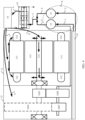
- FIG. 2 is a schematic diagram of a powertrain according to an embodiment of the present invention.
- the powertrain shown in the figure includes an oil pan 10, a motor 11, a reducer 12, and a cooling system.
- the cooling system includes a heat exchanger 14 and at least two oil pumps.
- the figure shows an implementation in which the at least two oil pumps include an electronic oil pump 13 and a mechanical oil pump 15.
- the at least two oil pumps deliver, to the heat exchanger 14, cooling oil sucked from the oil pan 10.
- the heat exchanger 14 is configured to cool the cooling oil sucked by the at least two oil pumps.
- An oil outlet port of the heat exchanger 14 is connected to an oil passage in the motor 11 and an oil passage in the reducer 12, so that a part of the cooling oil cools the motor 11 through the oil passage in the motor 11, and another part of the cooling oil cools the reducer 12 through the oil passage in the reducer 12.
- the plurality of oil pumps jointly provide required cooling oil for the powertrain, to ensure that a sufficient flow rate of cooling oil can be provided.
- a part of the cooling oil transmitted by the plurality of oil pumps is used to cool the motor, and another part is used to cool the reducer, to ensure good heat dissipation of the powertrain, and improve a cooling effect of the cooling system for the powertrain.
- the powertrain includes a cooling system, a motor 11, and a reducer 12.
- the cooling system includes an electronic oil pump 13, a mechanical oil pump 15, and a heat exchanger 14.
- the mechanical oil pump 15 is rigidly connected to a rotating component of the powertrain, so as to be driven by the motor 11 or the reducer 12.
- the mechanical oil pump 15 is rigidly connected to any rotating shaft of the reducer 12, and driven by the rotating shaft of the reducer 12. In some other embodiments, the mechanical oil pump 15 may alternatively be rigidly connected to an input shaft of the reducer, and driven by the input shaft of the reducer 12. In still some other embodiments, the mechanical oil pump 15 may alternatively be rigidly connected to a rotating shaft 114 of the motor 11, and driven by the rotating shaft 114.
- the motor 11 and the reducer 12 share an oil pan 10 at the bottom.
- the oil pan 10 includes a reducer oil return port and a motor oil return port. Cooling oil for cooling the reducer 12 enters the oil pan 10 through the reducer oil return port, and cooling oil for cooling the motor 11 enters the oil pan 10 through the motor oil return port.
- the mechanical oil pump 15 and the electronic oil pump 13 each include an oil suction port, to suck oil through different oil suction ports.
- an oil passage from which the mechanical oil pump 15 sucks oil is an oil passage 1
- an oil passage from which the electronic oil pump 13 sucks oil is an oil passage 2.
- FIG. 3 a schematic diagram 1 of an oil passage shown in FIG. 3 .
- An area A1 in FIG. 3 corresponds to an area A in FIG. 2 .
- the mechanical oil pump 15 and the electronic oil pump 13 share one oil suction port.
- An oil passage 3 and an oil passage 4 that are shown in FIG. 2 converge into an oil passage 5 and then are connected to an oil inlet port of the heat exchanger 14, and an oil outlet port of the heat exchanger 14 is connected to an oil passage 7, an oil passage 8, and an oil passage 9 by using an oil passage 6.
- FIG. 4 refers to a schematic diagram of a powertrain shown in FIG. 4 .
- the heat exchanger 14 is connected to a cavity 16 by using the oil passage 6, and the cavity 16 is connected to the oil passage 7, the oil passage 8, and the oil passage 9.
- the cavity 16 has a specific volume, so that pressure fluctuation in the cavity 16 is small, making it easy to distribute a flow rate of cooling oil from the cavity.
- a specific shape of the cavity 16 is not limited in this embodiment of this invention. In an actual application, the specific shape of the cavity 16 is adapted to each oil passage and a percentage of a flow rate of cooling oil in the oil passage.
- An outer ring of a motor stator is provided with a cooling oil passage. Cooling oil in the oil passage 7 is used to cool the motor stator, that is, cool a motor stator silicon steel sheet 111 and an end winding 112.
- Cooling oil in the oil passage 8 is used to cool a motor rotor, that is, cool a magnet steel 113 and the rotating shaft 114.
- the motor rotor is cooled by splashing oil.
- Cooling oil in the oil passage 9 is used to cool the reducer 12.
- the reducer 12 is cooled by spraying oil.
- the oil passage 9 actively sprays cooling oil to the reducer 12, to provide cooling oil required by the reducer 12.
- the reducer may use a dry oil pan, that is, cooling does not need to be performed by churning oil by a gear, which effectively reduces an oil churning loss of the gear of the reducer 12 during rotation at a high speed, and improves transmission efficiency of the reducer.
- the oil pan 10 is provided with a reducer oil return port and a motor oil return port. Cooling oil for cooling the reducer enters the oil pan 10 through the reducer oil return port, and cooling oil for cooling the motor enters the oil pan 10 through the motor oil return port.
- a one-way valve is disposed in the electronic oil pump 13, so that cooling oil can flow only from the oil passage 2 to the oil passage 4, to prevent high-pressure cooling oil in the oil passage 3 from being diverted to the oil passage 4 and damaging the electronic oil pump 13 when the mechanical oil pump 15 has a large oil suction flow rate due to a high rotational speed of the motor 11.
- the one-way valve may alternatively be disposed in an oil outlet passage, that is, the oil passage 4, of the electronic oil pump 13.
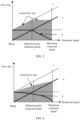
- FIG. 5 is a diagram 1 of a relationship between a flow rate of cooling oil transmitted by an oil pump and a rotational speed of a motor according to an embodiment of this invention.
- a line a represents a relationship between a flow rate of cooling oil transmitted by the mechanical oil pump 15 and the rotational speed of the motor
- a line b represents a relationship between a flow rate of cooling oil transmitted by the electronic oil pump 13 and the rotational speed of the motor.
- a motor blocking scenario usually occurs when the electric vehicle is started in a cold environment.
- the heated coolant flows through a power battery pack of the electric vehicle via a pipe, to heat the power battery pack, and improve discharge performance of the power battery pack.
- an inflection-point rotational speed is a rotational speed that is of the motor and that corresponds to an intersection between a relationship curve between rated output torque of the motor and the rotational speed of the motor, and a relationship curve between rated output power of the motor and the rotational speed of the motor.
- the inflection-point rotational speed is pre-calibrated.
- the electronic oil pump 13 may operate by rotating forward at a full rotational speed. After the rotational speed of the motor is greater than the inflection-point rotational speed, the electronic oil pump 13 gradually decreases the rotational speed.
- the electronic oil pump 13 is controlled by a motor control unit (Motor Control Unit, MCU).
- the MCU in this embodiment of this invention may be an application-specific integrated circuit (Application-Specific Integrated Circuit, ASIC), a programmable logic device (Programmable Logic Device, PLD), a digital signal processor (Digital Signal Processor, DSP), or a combination thereof.
- the PLD may be a complex programmable logic device (Complex Programmable Logic Device, CPLD), a field-programmable gate array (Field-Programmable Gate Array, FPGA), a general array logic (Generic Array Logic, GAL), or any combination thereof. This is not specifically limited in this embodiment of this invention.
- a vehicle control unit (Vehicle Control Unit, VCU) generates corresponding rotational speed information based on a current rotational speed of the motor 11 of the electric vehicle, and the VCU sends the rotational speed information to the MCU, so that the MCU controls an operating status of the electronic oil pump 13.
- the MCU may measure the rotational speed of the motor 11 itself.
- the MCU monitors a temperature of the motor 11 in real time and controls the operating status of the electronic oil pump 13 based on the temperature of the motor 11.
- a correspondence between the temperature of the motor 11 and the rotational speed of the electronic oil pump 13 may be pre-calibrated and stored.
- the correspondence between the temperature of the motor 11 and the rotational speed of the electronic oil pump 13 is stored in a form of a data table.
- a function relationship between the temperature of the motor 11 and the rotational speed of the electronic oil pump 13 is stored, to facilitate real-time calculation.
- the mechanical oil pump 15 is used as a main oil pump to provide cooling oil required by the powertrain
- the electronic oil pump 13 is used as an auxiliary oil pump.
- the MCU may control the electronic oil pump 13 to gradually decrease the rotational speed, so that power consumption of the electronic oil pump 13 can be reduced.
- an actual flow rate of cooling oil delivered by the cooling system to the powertrain corresponds to a boundary of a gray area indicated by an arrow in the figure.
- a maximum value of a theoretical flow rate of cooling oil delivered by the cooling system to the powertrain corresponds to a line c in the figure.
- the MCU may also control the electronic oil pump 13 to operate by rotating forward at the full rotational speed.
- the cooling system delivers cooling oil to the powertrain based on the line c, to provide a maximum flow rate of cooling oil to the powertrain.
- the preset rotational speed in the foregoing description is not specifically limited in this embodiment of this invention. In some embodiments, the preset rotational speed is pre-calibrated and stored.
- FIG. 6 is a diagram 2 of a relationship between a flow rate of cooling oil transmitted by an oil pump and a rotational speed of a motor according to an embodiment of this invention.
- an operating principle of the mechanical oil pump 15 is the same as that described above, and a difference lies in that the rotational speed of the electronic oil pump 13 is negatively correlated to the rotational speed of the motor 11 except for a blocked condition.
- the rotational speed of the motor 11 increases, the flow rate of cooling oil delivered by the mechanical oil pump 15 to the powertrain rapidly increases, the flow rate of cooling oil delivered by the electronic oil pump 13 to the powertrain gradually decreases, but an overall flow rate of cooling oil delivered by the cooling system to the powertrain increases, to meet a cooling requirement of the powertrain.
- the cooling system includes one mechanical oil pump and one electronic oil pump.
- the cooling system may alternatively include one mechanical oil pump and at least two electronic oil pumps, and each electronic oil pump is controlled by the MCU.
- each electronic oil pump is controlled by the MCU.
- the operating manner of each electronic oil pump refer to the operating manners of the electronic oil pump 13. Details are not described herein again in this embodiment of this invention.
- the electronic oil pump and the mechanical oil pump jointly provide required cooling oil for the powertrain, to improve a cooling effect of the cooling system for the powertrain.
- the mechanical oil pump is a main oil pump
- the electronic oil pump is an auxiliary oil pump.
- the mechanical oil pump is rigidly connected to a transmission component of the reducer, so that the rotational speed of the mechanical oil pump is positively correlated to the rotational speed of the motor.
- the mechanical oil pump correspondingly increases the flow rate of cooling oil delivered to the powertrain, to meet a cooling requirement of the powertrain.
- the mechanical oil pump has a smaller size, and can provide a greater flow rate of cooling oil than the electronic oil pump when the powertrain generates serious heat due to a high rotational speed of the motor.
- the electronic oil pump needs to provide required cooling oil only when the motor is blocked and when the motor runs at a low rotational speed, so that required performance of the electronic oil pump can be reduced, and an electronic oil pump with a smaller size and lower costs can be selected.
- the cavity can be adapted to each oil passage and the percentage of the flow rate of cooling oil in the oil passage.
- cooling oil required by the reducer is provided by actively spraying cooling oil to the reducer, so that the reducer does not need to be cooled by churning oil by a gear, which effectively reduces an oil churning loss of the gear of the reducer during rotation at a high speed, and improves transmission efficiency of the reducer.
- each electronic oil pump when the powertrain is applied to a single-motor powertrain, only two or more electronic oil pumps may be provided.
- each electronic oil pump is controlled by the MCU.
- a rotational speed of each electronic oil pump is positively correlated to the rotational speed of the motor.
- each electronic oil pump correspondingly increases a flow rate of cooling oil delivered to the powertrain, to meet a cooling requirement of the powertrain.
- the MCU may obtain the rotational speed information of the motor by using the VCU or measure the rotational speed of the motor itself.
- the rotational speed of each electronic oil pump is positively correlated to the temperature of the motor, and the MCU controls the rotational speed of each electronic oil pump based on a temperature of the motor detected in real time.
- a correspondence between the temperature of the motor and the rotational speed of the electronic oil pump may be pre-calibrated.
- the powertrain described above may alternatively be provided with a plurality of heat exchangers, and each heat exchanger is configured to cool cooling oil transmitted by one oil pump. Details are not described herein.
- FIG. 7A is a schematic diagram of still another powertrain according to an embodiment of this invention.
- the powertrain shown in the figure includes a first motor 11, a second motor 11B, a first reducer 12, a second reducer 12B, and a cooling system.
- the first motor 11 and the second motor 11B have a same specific implementation and operating principle, and the first reducer 12 and the second reducer 12B have a same specific implementation and operating principle.
- the cooling system includes an electronic oil pump 13, a mechanical oil pump 15, a heat exchanger 14, and a cavity 16.
- the mechanical oil pump 15 is rigidly connected to a rotating component of the powertrain, so as to be driven by the first motor 11 or the first reducer 12.
- the mechanical oil pump 15 is rigidly connected to a rotating shaft of the first reducer 12, and driven by the rotating shaft of the first reducer 12. It may be understood that in some other embodiments, the mechanical oil pump 15 may alternatively be rigidly connected to a rotating shaft of the second reducer 12B, and driven by the rotating shaft of the second reducer 12B.
- the first motor 11, the second motor 11B, the first reducer 12, and the second reducer 12B share an oil pan 10 at the bottom.
- the oil pan 10 includes a reducer oil return port and a motor oil return port. Cooling oil for cooling the first reducer 12 and the second reducer 12B enters the oil pan 10 through the reducer oil return port, and cooling oil for cooling the first motor 11 and the second motor 11B enters the oil pan 10 through the motor oil return port.
- a plurality of reducer oil return ports and a plurality of motor oil return ports may be disposed, which are distributed at different positions.
- the mechanical oil pump 15 and the electronic oil pump 13 respectively suck oil through different oil suction ports.
- an oil passage from which the mechanical oil pump 15 sucks oil is an oil passage 1
- an oil passage from which the electronic oil pump 13 sucks oil is an oil passage 2.
- FIG. 3 a schematic diagram 1 of an oil suction passage shown in FIG. 3 .
- An area A1 in FIG. 3 corresponds to an area A in FIG. 7A .
- the mechanical oil pump 15 and the electronic oil pump 13 share one oil suction port.
- An oil passage 3 and an oil passage 4 that are shown in FIG. 7A converge into an oil passage 5 and then are connected to the heat exchanger 14, and the heat exchanger 14 is connected to the cavity 16 by using an oil passage 6.
- the cavity 16 has a specific volume, so that pressure fluctuation in the cavity 16 is small, making it easy to distribute a flow rate of cooling oil from the cavity.
- the cavity 16 is connected to an oil passage 7, an oil passage 77, an oil passage 8, an oil passage 88, an oil passage 9, and an oil passage 99.
- flow rates of cooling oil of the oil passage 7 and the oil passage 77 are basically the same
- flow rates of cooling oil of the oil passage 8 and the oil passage 88 are basically the same
- flow rates of cooling oil of the oil passage 9 and the oil passage 99 are basically the same.
- Cooling oil in the oil passage 7 and the oil passage 77 is used to cool the motor stators of the two motors, that is, cool motor stator silicon steel sheets 111 and end windings 112.
- Cooling oil in the oil passage 8 and the oil passage 88 is used to cool motor rotors of the two motors, that is, cool magnet steels 113 and rotating shafts 114.
- the motor rotors of the two motors are cooled by splashing oil.
- Cooling oil in the oil passage 9 and the oil passage 99 is used to cool the first reducer 12 and the second reducer 12B by spraying oil.
- dry oil pans may be used, that is, the reducers do not need to be cooled by churning oil by gears, which effectively reduces oil churning losses of the gears of the reducers during rotation at a high speed, and improves transmission efficiency of the reducers.
- a one-way valve is disposed in the electronic oil pump 13, so that cooling oil can flow only from the oil passage 2 to the oil passage 4, to prevent high-pressure cooling oil in the oil passage 3 from being diverted to the oil passage 4 and damaging the electronic oil pump 13 when the mechanical oil pump 15 has a large oil suction flow rate due to a high rotational speed of the first motor 11.
- FIG. 7B is a schematic diagram of yet another powertrain according to an embodiment of this invention.
- the powertrain shown in FIG. 7B differs from that shown in FIG. 7A in including two heat exchangers.
- the electronic oil pump transmits cooling oil to a first heat exchanger 14 through the oil passage 4, and the mechanical oil pump 15 transmits cooling oil to a second heat exchanger 14B through the oil passage 3.
- Oil outlet ports of the first heat exchanger 14 and the second heat exchanger 14B converge and are connected to the cavity 16 by using the oil passage 6.
- the two heat exchangers respectively cool the cooling oil delivered by the two oil pumps, thereby improving a cooling effect of the cooling oil.
- an area B in FIG. 7B may alternatively be implemented in a manner of an area B1 shown in FIG. 7C , that is, the first heat exchanger 14 is connected to the cavity 16 by using an oil passage 6, and the second heat exchanger 14B is connected to the cavity 16 by using an oil passage 6B.
- oil outlet passages of the two heat exchangers do not directly converge, to prevent cooling oil of the second heat exchanger 14B from flowing into the first heat exchanger 14B due to high oil pressure at the oil outlet port caused by a high rotational speed of the motor 11.
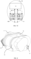
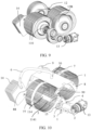
- FIG. 8 is a schematic diagram of appearance of a powertrain according to an embodiment of this invention.
- a housing 01 of the powertrain shown in the figure is configured to accommodate the motors, the reducers, and the mechanical oil pump.
- the electronic oil pump 13 is partially inside the housing 01 and partially outside the housing 01.
- the heat exchanger 14 is disposed outside the housing 01, and an oil outlet port of the heat exchanger 14 is connected to the cavity 16 of the powertrain by using the oil passage 6.
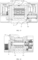
- FIG. 9 is a schematic diagram of an internal structure of a powertrain according to an embodiment of this invention.
- the two motors of the powertrain are placed side by side, and each motor drives one reducer.
- the outer rings of the motor stators 110 of the two motors are provided with cooling oil passages.
- the cooling oil passages are are respectively connected to the oil passage 7 and the oil passage 77 that are shown in FIG. 7A .
- FIG. 10 is a schematic diagram 1 of an oil passage in a powertrain according to an embodiment of this invention.
- the mechanical oil pump 15 and the electronic oil pump 13 are arranged on a same side, and the heat exchanger 14 is located on a different side.
- the mechanical oil pump 15 sucks oil through the oil passage 1 and delivers the oil through the oil passage 3.
- the electronic oil pump sucks oil through the oil passage 2 and delivers the oil through the oil passage 4.
- the oil passages 2 and 4 converge and then are connected to the heat exchanger 14 by using an axial oil passage 5, and the oil outlet port of the heat exchanger 14 is connected to the cavity 16 by using the oil passage 6.
- the cavity 16 is connected to the oil passage 7, the oil passage 77, the oil passage 8, the oil passage 88, the oil passage 9, and the oil passage 99.
- Cooling oil in the oil passage 7 and the oil passage 77 is used to cool the motor stators of the two motors.
- Cooling oil in the oil passage 8 and the oil passage 88 is used to cool the motor rotors of the two motors.
- the oil passage 8 and the oil passage 88 that are shown in the figure are connected to oil passages inside the rotating shafts 114.
- a plurality of rotating shaft oil outlet ports 1141 are further disposed on the rotating shafts 114. When the rotating shafts rotate, cooling oil is splashed out from the rotating shaft oil outlet ports 1141 to cool the motor rotors.
- the oil passage 9 sprays cooling oil through an oil outlet port to cool the first reducer 12.
- the oil passage 99 sprays cooling oil through an oil outlet port to cool the second reducer 12B.
- the reducers are cooled by spraying cooling oil instead of churning oil by gears, so that on one hand, the cooling oil can be in fuller contact with the reducers, and on the other hand, oil churning losses of the gears of the reducers are reduced.
- FIG. 11 is a schematic diagram 2 of an oil passage in a powertrain according to an embodiment of this invention.
- FIG. 11 oil passages corresponding to one motor are hidden, to more clearly show that the oil passages 2 and 4 converge and then are connected to the heat exchanger 14 by using the axial oil passage 5.
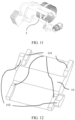
- FIG. 12 is a schematic diagram of an oil pan of a powertrain according to an embodiment of this invention.
- the oil pan has a motor oil return port 101 corresponding to each of bottom positions at two ends of each motor, and a reducer oil return port 102 corresponding to a bottom position of each reducer.
- Each motor oil return port 101 and each reducer oil return port 102 are connected to the oil pan 10 located at the bottom of the motor.
- cooling oil for cooling the motor enters the oil pan 10 through the motor oil return port 101
- cooling oil for cooling the reducer enters the oil pan 10 through the reducer oil return port 102.
- the oil passage 1 and the oil passage 2 are connected to the oil pan 10, so that the electronic oil pump 13 sucks oil through the oil passage 1, and the mechanical oil pump 15 sucks oil through the oil passage 2.
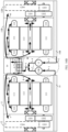
- FIG. 13 is a schematic cross-sectional view 1 of a powertrain according to an embodiment of this invention.
- FIG. 14 is a schematic cross-sectional view 2 of a powertrain according to an embodiment of this invention.
- FIG. 15 is a schematic cross-sectional view 3 of a powertrain according to an embodiment of this invention.
- a cross-sectional direction of FIG. 15 is perpendicular to cross-sectional directions of FIG. 13 and FIG. 14 .
- the two motors when the powertrain includes two motors, the two motors may alternatively be disposed coaxially, that is, rotating shafts of the two motors are disposed in parallel, or the two motors share a rotating shaft.
- an operating principle of a cooling system and distribution of oil passages of the motors are similar to those described above. Details are not described herein again in this embodiment of this invention.
- the electronic oil pump and the mechanical oil pump jointly provide required cooling oil for the powertrain, to improve a cooling effect of the cooling system for the powertrain.
- the mechanical oil pump is a main oil pump
- the electronic oil pump is an auxiliary oil pump.
- the mechanical oil pump is rigidly connected to a transmission component of a reducer, so that the rotational speed of the mechanical oil pump is positively correlated to a rotational speed of a motor.
- the mechanical oil pump correspondingly increases the flow rate of cooling oil delivered to the powertrain, to meet a cooling requirement of the powertrain.
- the mechanical oil pump has a smaller size, and can provide a greater flow rate of cooling oil than the electronic oil pump when the powertrain generates serious heat due to a high rotational speed of the motor.
- the electronic oil pump needs to provide required cooling oil only when the motor is blocked and when the motor runs at a low rotational speed, so that required performance of the electronic oil pump can be reduced, and an electronic oil pump with a smaller size and lower costs can be selected.
- cooling oil required by the reducers is provided by actively spraying cooling oil to the reducers, so that the reducers do not need to be cooled by churning oil by gears, which effectively reduces oil churning losses of the gears of the reducers during rotation at a high speed, and improves transmission efficiency of the reducers.
- a plurality of motors have a same rotational speed.
- a rotational speed of a motor in the following description represents a rotational speed of each motor, and a temperature of a motor in the following description represents a temperature of each motor.
- FIG. 16A is a schematic diagram of another powertrain according to an embodiment of this invention.
- the powertrain shown in the figure includes a first motor 11, a second motor 11B, a first reducer 12, a second reducer 12B, and a cooling system.
- the first motor 11 and the second motor 11B have a same specific implementation and operating principle, and the first reducer 12 and the second reducer 12B have a same specific implementation and operating principle.
- the cooling system includes an electronic oil pump 13, an electronic oil pump 13B, a heat exchanger 14, and a cavity 16.
- both electronic oil pumps are controlled by an MCU of an electric vehicle.
- a rotational speed of each electronic oil pump is positively correlated to a rotational speed of the motor.
- each electronic oil pump correspondingly increases a flow rate of cooling oil delivered to the powertrain, to meet a cooling requirement of the powertrain.
- the MCU may obtain rotational speed information of the motors by using a VCU.
- the MCU may alternatively measure the rotational speed of the motor 11 itself.
- a correspondence between the rotational speed of the electronic oil pump and the rotational speed of the motor is pre-calibrated. The correspondence may be stored in a form of a data table after calibrated, or stored in a form of a function relationship after calibrated.
- the rotational speed of each electronic oil pump is positively correlated to a temperature of the motor, and the MCU controls the rotational speed of each electronic oil pump based on a temperature of the motor detected in real time.
- a correspondence between the temperature of the motor and the rotational speed of the electronic oil pump may be pre-calibrated. The correspondence may be stored in a form of a data table after calibrated, or stored in a form of a function relationship after calibrated.
- FIG. 16B is a schematic diagram of another powertrain according to an embodiment of this invention.
- a difference between the powertrain shown in FIG. 16B and that in FIG. 16A lies in that an oil pan of the powertrain is divided into two parts that do not communicate with each other, respectively corresponding to a first oil chamber 10 and a second oil chamber 10B in the figure.
- a difference between the powertrain shown in FIG. 16B and that in FIG. 16A lies in that the powertrain includes two oil pans, a first oil pan includes a first oil chamber 10, and a second oil pan includes a second oil chamber 10B.
- the first oil pan 10 includes a first reducer oil return port and a first motor oil return port
- the second oil pan 10B includes a second reducer oil return port and a second motor oil return port.
- Cooling oil for cooling the first reducer 12 enters the first oil chamber 10 through the first reducer oil return port
- cooling oil for cooling the first motor 11 enters the first oil chamber 10 through the first motor oil return port
- cooling oil for cooling the second reducer 12B enters the second oil chamber 10B through the second reducer oil return port
- cooling oil for cooling the second motor 11B enters the second oil chamber 10B through the second motor oil return port.
- the two oil chambers are separated, to prevent an oil suction flow rate of one electronic oil pump from decreasing due to uneven distribution of cooling oil in the oil pans when the electric vehicle is in a slope or turning state.
- the electronic oil pump 13 sucks oil from the second oil chamber 10B through an oil passage 2, and the electronic oil pump 13B sucks oil from the first oil chamber 10 through an oil passage 1.
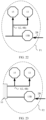
- FIG. 17 refers to a schematic diagram 3 of an oil passage shown in FIG. 17 .
- An area C1 in FIG. 17 corresponds to an area C in FIG. 16A .
- the electronic oil pump 13 and the electronic oil pump 13B share one suction port.
- two electronic oil pumps suck oil.
- an electronic oil pump with a small size and low costs may be selected for the two electronic oil pumps.
- FIG. 18A is a schematic diagram of yet another powertrain according to an embodiment of this invention.
- the powertrain shown in the figure differs from the powertrain shown in FIG. 16A in including two heat exchangers: a first heat exchanger 14 and a second heat exchanger 14B.
- An oil inlet port of the first heat exchanger 14 is connected to an oil passage 4 to cool cooling oil transmitted by the electronic oil pump 13, and an oil inlet port of the second heat exchanger 14B is connected to an oil passage 3 to cool cooling oil transmitted by the electronic oil pump 13B.
- the two heat exchangers respectively cool the cooling oil delivered by the two oil pumps, thereby improving a cooling effect of the cooling oil.
- oil outlet ports of the first heat exchanger 14 and the second heat exchanger 14B converge and are connected to a cavity 16 by using an oil passage 6.
- an area B1 shown in FIG. 7C corresponds to an area D in FIG. 18 .
- oil outlet passages of the two heat exchangers do not directly converge, to prevent cooling oil of one of the heat exchangers from flowing into the other heat exchanger due to high oil pressure at an oil outlet port caused by uneven distribution of oil accumulated in the oil pan 10 when the electric vehicle tilts.
- FIG. 18B is a schematic diagram of another powertrain according to an embodiment of this invention.
- a difference between the powertrain shown in FIG. 18B and that in FIG. 18A lies in that a first oil chamber 10 and a second oil chamber 10B do not communicate with each other.
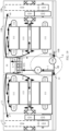
- FIG. 19 is a schematic diagram of still another powertrain according to an embodiment of this invention.
- the powertrain shown in the figure includes a first motor 11, a second motor 11B, a first reducer 12, a second reducer 12B, and a cooling system.
- a first oil chamber 10 and a second oil chamber 10B that are shown in the figure, refer to the foregoing embodiment.
- a total space occupied by two oil pans can be appropriately reduced, to reduce a space occupied by the powertrain.
- the two oil chambers do not communicate with each other, to avoid uneven distribution of cooling oil in the oil pans when an electric vehicle is in a slope or turning state.
- the first motor 11 and the second motor 11B have a same specific implementation and operating principle, and the first reducer 12 and the second reducer 12B have a same specific implementation and operating principle.
- the cooling system includes an electronic oil pump 13B, a mechanical oil pump 15, a heat exchanger 14, and a cavity 16.
- the electronic oil pump 13B sucks oil from the second oil chamber 10B through an oil passage 2B, and transmits the cooling oil to the first oil chamber 10 through an oil passage 4B.
- the mechanical oil pump 15 sucks oil from the first oil chamber 10.
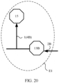
- FIG. 20 refers to a schematic diagram 4 of an oil passage shown in FIG. 20 .
- An area E1 in FIG. 20 corresponds to an area E in FIG. 19 , and an oil outlet port of the electronic oil pump 13B and an oil suction port of the mechanical oil pump 15 converge.
- the mechanical oil pump 15 sucks oil from the first oil chamber 10 and the oil outlet port of the electronic oil pump 13B.
- a rotational speed of the electronic oil pump 13B during operation is controlled by an MCU.
- the MCU controls the rotational speed of the electronic oil pump 13B based on a current rotational speed of the motor.
- the rotational speed of the electronic oil pump 13B is positively correlated to the rotational speed of the motor, and a correspondence between the rotational speed of the electronic oil pump 13B and the rotational speed of the motor is pre-calibrated.
- the correspondence may be stored in a form of a data table after calibrated, or stored in a form of a function relationship after calibrated.
- a VCU generates corresponding rotational speed information based on the current rotational speed of the motor of the electric vehicle, and the VCU sends the rotational speed information to the MCU, so that the MCU controls an operating status of the electronic oil pump 13B.
- the MCU may alternatively measure the rotational speed of the motor itself.
- the MCU monitors a temperature of the motor in real time, and controls the operating status of the electronic oil pump 13B based on the temperature of the motor.
- the rotational speed of the electronic oil pump 13B is positively correlated to the temperature of the motor, and a correspondence between the temperature of the motor and the rotational speed of the electronic oil pump 13B may be pre-calibrated and stored.
- the correspondence may be stored in a form of a data table after calibrated, or stored in a form of a function relationship after calibrated.
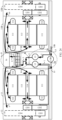
- FIG. 21 is a schematic diagram of yet another powertrain according to an embodiment of this invention.
- the powertrain shown in the figure includes a first motor 11, a second motor 11B, a first reducer 12, a second reducer 12B, and a cooling system.
- the first motor 11 and the second motor 11B have a same specific implementation and operating principle
- the first reducer 12 and the second reducer 12B have a same specific implementation and operating principle.
- the cooling system includes two electronic oil pumps: a first electronic oil pump 13 and a second electronic oil pump 13B, and further includes a mechanical oil pump 15, as well as a heat exchanger 14 and a cavity 16.
- the second electronic oil pump 13B sucks oil from the second oil chamber 10B through an oil passage 2B, and transmits the cooling oil to the first oil chamber 10 through an oil passage 4B.
- the mechanical oil pump 15 sucks oil from the first oil chamber 10 through an oil passage 1.
- the first electronic oil pump 13 sucks oil from the first oil chamber 10 through an oil passage 2.
- a one-way valve is disposed in the first electronic oil pump 13, to prevent high-pressure cooling oil in the oil passage 3 from being diverted to the oil passage 4 and damaging the first electronic oil pump 13 when the mechanical oil pump 15 has a large oil suction flow rate due to a high rotational speed of the first motor 11.
- a motor blocking scenario usually occurs when the electric vehicle is started in a cold environment.
- the heated coolant flows through a power battery pack of the electric vehicle via a pipe, to heat the power battery pack, and improve discharge performance of the power battery pack.
- Rotational speeds of the first electronic oil pump 13 and the second electronic oil pump 13B during operation are controlled by an MCU.
- the MCU determines the rotational speed of the second electronic oil pump 13B based on a current total oil suction flow rate of the first electronic oil pump 13 and the mechanical oil pump 15.
- the rotational speed of the second electronic oil pump 13B is positively correlated to the total oil suction flow rate, and a correspondence between the total oil suction flow rate and the rotational speed of the second electronic oil pump 13B is pre-calibrated.
- the correspondence may be stored in a form of a data table after calibrated, or stored in a form of a function relationship after calibrated. In this case, a larger total oil suction flow rate indicates that an oil suction flow rate of the second electronic oil pump 13B increases correspondingly.
- the MCU generally controls the oil suction flow rate of the second electronic oil pump 13B to be equal to half of the total oil suction flow rate, so as to maintain a basically same flow rate of cooling oil in the first oil chamber 10 and the second oil chamber 10B.
- the MCU determines the rotational speed of the second electronic oil pump 13B with reference to a current rotational speed of the first electronic oil pump 13 and a current rotational speed of the mechanical oil pump 15.
- a relationship between the rotational speed of the second electronic oil pump 13B, the rotational speed of the first electronic oil pump 13, and the rotational speed of the mechanical oil pump 15 is pre-calibrated.
- the rotational speed of the second electronic oil pump is positively correlated to a sum of the current rotational speed of the first electronic oil pump and the current rotational speed of the mechanical oil pump, to maintain a basically same flow rate of cooling oil in the first oil chamber 10 and the second oil chamber 10B.
- FIG. 22 is a schematic diagram 5 of an oil passage according to this invention.
- An area F1 in FIG. 22 corresponds to an area F in FIG. 21 .
- oil suction ports of the mechanical oil pump 15 and the first electronic oil pump 13 converge, and then converge with an oil outlet port of the second electronic oil pump 13B.
- the mechanical oil pump 15 and the first electronic oil pump 13 suck oil from the first oil chamber 10 and the oil outlet port of the second electronic oil pump 13B.
- FIG. 23 is a schematic diagram 6 of an oil passage according to this invention.
- An area F2 in FIG. 23 corresponds to the area F in FIG. 21 .
- the oil suction ports of the mechanical oil pump 15 and the first electronic oil pump 13 converge, and both suck oil from the first oil chamber 10.
- An area G in FIG. 21 may alternatively be implemented in the manner shown in FIG. 7C , that is, the powertrain is provided with two heat exchangers to respectively cool cooling oil delivered by the two oil pumps, thereby improving a cooling effect of the cooling oil.
- a first heat exchanger 14 is connected to the cavity 16 by using an oil passage 6, and a second heat exchanger 14B is connected to the cavity 16 by using an oil passage 6B.
- Oil outlet passages of the two heat exchangers shown in FIG. 7C do not directly converge, to prevent cooling oil of the second heat exchanger 14B from flowing into the first heat exchanger 14 due to high oil pressure at an oil outlet port caused by a high rotational speed of the motor 11.
- the oil outlet passages of the two heat exchangers may alternatively first converge and then connect to the cavity 16.
- FIG. 24 is a schematic diagram of another powertrain according to an embodiment of this invention.
- the first electronic oil pump 13 and the second electronic oil pump 13B may have oil suction ports independent of each other, or may share one oil suction port. This is not specifically limited in this embodiment of this invention.
- the MCU controls the second electronic oil pump 13B to operate by rotating reversely at a full rotational speed to transmit cooling oil in the first oil chamber 10 to the second oil chamber 10B, so as to maintain a basically same flow rate of cooling oil in the first oil chamber 10 and the second oil chamber 10B.
- the MCU determines a rotational speed of the second electronic oil pump 13B based on a current oil suction flow rate difference between the first electronic oil pump 13 and the mechanical oil pump 15.
- the rotational speed of the second electronic oil pump 13B is positively correlated to the oil suction flow rate difference, and the correspondence between the rotational speed of the second electronic oil pump 13B and the oil suction flow rate difference is pre-calibrated.
- the correspondence may be stored in a form of a data table after calibrated, or stored in a form of a function relationship after calibrated.
- the MCU controls the rotational speed of the second electronic oil pump 13B so that an oil suction flow rate of the second electronic oil pump 13B is equal to half of the oil suction flow rate difference, so as to maintain a basically same flow rate of cooling oil in the first oil chamber 10 and the second oil chamber 10B.
- the electronic oil pump and the mechanical oil pump jointly provide required cooling oil for the powertrain, to improve a cooling effect of the cooling system for the powertrain.
- the mechanical oil pump is a main oil pump
- the electronic oil pump is an auxiliary oil pump.
- the mechanical oil pump is rigidly connected to a transmission component of a reducer, so that the rotational speed of the mechanical oil pump is positively correlated to a rotational speed of a motor.
- the mechanical oil pump correspondingly increases the flow rate of cooling oil delivered to the powertrain, to meet a cooling requirement of the powertrain.
- the mechanical oil pump has a smaller size, and can provide a greater flow rate of cooling oil than the electronic oil pump when the powertrain generates serious heat due to a high rotational speed of the motor.
- One electronic oil pump needs to provide required cooling oil only when the motor is blocked and when the motor runs at a low rotational speed, and the other electronic oil pump needs to transmit cooling oil only between oil pans on two sides, so that required performance of the electronic oil pump can be reduced, and an electronic oil pump with a smaller size and lower costs can be selected.
- cooling oil required by the reducers is provided by actively spraying cooling oil to the reducers, so that the reducers do not need to be cooled by churning oil by gears, which effectively reduces oil churning losses of the gears of the reducers during rotation at a high speed, and improves transmission efficiency of the reducers.
- an embodiment of this invention further provides an electric vehicle to which the powertrain is applied, which is specifically described below with reference to an accompanying drawing.
- FIG. 25 is a schematic diagram of an electric vehicle according to an embodiment of this invention.
- the electric vehicle 2300 provided in this embodiment of this invention includes a power battery pack 2301 and a powertrain 2302.
- the power battery pack 2301 is configured to supply required electric energy to the powertrain 2302.
- the powertrain 2302 is configured to convert the electrical energy supplied by the power battery pack into mechanical energy to drive the electric vehicle.
- the powertrain 2302 may be a single-motor powertrain or a multi-motor powertrain. This is not specifically limited in this embodiment of this invention.
- a plurality of oil pumps jointly provide required cooling oil for the powertrain, to ensure that a sufficient flow rate of cooling oil can be provided.
- a part of the cooling oil transmitted by the plurality of oil pumps is used to cool a motor, and another part is used to cool a reducer, to ensure good heat dissipation of the powertrain, and improve a cooling effect of a cooling system for the powertrain.
- the mechanical oil pump is a main oil pump, and the electronic oil pump is an auxiliary oil pump.
- the mechanical oil pump is rigidly connected to a transmission component of the reducer, so that a rotational speed of the mechanical oil pump is positively correlated to a rotational speed of the motor.
- the mechanical oil pump correspondingly increases a flow rate of cooling oil delivered to the powertrain, to meet a cooling requirement of the powertrain.
- the mechanical oil pump has a smaller size, and can provide a greater flow rate of cooling oil than the electronic oil pump when the powertrain generates serious heat due to a high rotational speed of the motor.
- the electronic oil pump needs to provide required cooling oil only when the motor is blocked and when the motor runs at a low rotational speed, so that required performance of the electronic oil pump can be reduced, and an electronic oil pump with a smaller size and lower costs can be selected.
- a plurality of electronic oil pumps may provide the required cooling oil for the powertrain, to reduce a performance requirement on each electronic oil pump, so that a plurality of electronic oil pump with a small size and low costs may be selected.
- the correspondence that is pre-calibrated and stored may be stored in a form of a data table, and is determined by searching the data table when the correspondence is to be used.
- the correspondence that is pre-calibrated and stored may be stored in a form of a function relationship, the function relationship is invoked when the correspondence is to be used, and a result is determined through calculation.
- At least one (piece) of a, b, or c may represent: a, b, c, "a and b", “a and c", “b and c", or "a, b, and c", where a, b, and c may be singular or plural.
Landscapes
- Engineering & Computer Science (AREA)
- Chemical & Material Sciences (AREA)
- Combustion & Propulsion (AREA)
- Transportation (AREA)
- Mechanical Engineering (AREA)
- Power Engineering (AREA)
- General Details Of Gearings (AREA)
Description
- This invention relates to the field of motor cooling technologies, and in particular, to a powertrain and an electric vehicle.
- A powertrain of an electric vehicle includes a motor and a reducer. The motor is configured to convert electric energy supplied by a power battery pack of the electric vehicle into mechanical energy. The reducer is configured to transmit the mechanical energy generated by the motor to a wheel of the electric vehicle, so as to drive the electric vehicle to run. As a power transmission component, the reducer mainly includes components such as a gear, a bearing, and a housing.
- For a powertrain using oil cooling, cooling oil is mainly driven by an electric oil pump to circulate heat between the inside of the powertrain and a heat exchanger for lubrication and cooling. As a result, a motor cooling effect depends on performance of the electric oil pump and the heat exchanger.
- As the powertrain continuously evolves towards miniaturization, and a maximum rotational speed of the powertrain also needs to be increased continuously, a same power output with a smaller size means that a heat density increases. In addition, miniaturization of a motor leads to a smaller oil passage for cooling oil to circulate in the motor. As a result, flow resistance of the cooling oil flowing in the oil passage is increased and a flow rate is decreased, thereby reducing a cooling effect of the cooling oil for the motor, that is, a cooling effect of a cooling system for the powertrain is poor.
The documentUS 2021/0039491 A1 shows a drive unit for an electric vehicle. A motor and a reducer are supplied by cooling oil from an oil pan, by a single oil pump.
Thedocument DE 10 2018 121 203 A1 shows a cooling unit for an electrical motor. The electrical motor comprises two independent cooling circuits, which are supplied with cooling oil by two independent oil pumps.
Thedocument EP 3 517 745 A1 shows a vehicle drive system comprising an electrical motor and two oil pumps. The two oil pumps, connected to different parts of the motor. - To resolve the foregoing problem, this invention provides a powertrain and an electric vehicle, to improve a cooling effect of a cooling system for the powertrain. The present invention is defined by the independent claims. Further advantageous developments are shown by the dependent claims.
-
-
FIG. 1 is a schematic diagram of an existing powertrain and a cooling system of the powertrain; -
FIG. 2 is a schematic diagram of a cooling system of a powertrain according to an embodiment of this invention; -
FIG. 3 is a schematic diagram 1 of an oil passage according to an embodiment of this invention; -
FIG. 4 is a schematic diagram of another powertrain according to an embodiment of this invention; -
FIG. 5 is a diagram 1 of a relationship between a flow rate of cooling oil transmitted by an oil pump and a rotational speed of a motor according to an embodiment of this invention; -
FIG. 6 is a diagram 2 of a relationship between a flow rate of cooling oil transmitted by an oil pump and a rotational speed of a motor according to an embodiment of this invention; -
FIG. 7A is a schematic diagram of still another powertrain according to an embodiment of this invention; -
FIG. 7B is a schematic diagram of yet another powertrain according to an embodiment of this invention; -
FIG. 7C is a schematic diagram 2 of an oil passage according to an embodiment of this invention; -
FIG. 8 is a schematic diagram of appearance of a powertrain according to an embodiment of this invention; -
FIG. 9 is a schematic diagram of an internal structure of a powertrain according to an embodiment of this invention; -
FIG. 10 is a schematic diagram 1 of an oil passage in a powertrain according to an embodiment of this invention; -
FIG. 11 is a schematic diagram 2 of an oil passage in a powertrain according to an embodiment of this invention; -
FIG. 12 is a schematic diagram of an oil pan of a powertrain according to an embodiment of this invention; -
FIG. 13 is a schematiccross-sectional view 1 of a powertrain according to an embodiment of this invention; -
FIG. 14 is a schematiccross-sectional view 2 of a powertrain according to an embodiment of this invention; -
FIG. 15 is a schematiccross-sectional view 3 of a powertrain according to an embodiment of this invention; -
FIG. 16A is a schematic diagram of another powertrain according to an embodiment of this invention; -
FIG. 16B is a schematic diagram of still another powertrain according to an embodiment of this invention; -
FIG. 17 is a schematic diagram 3 of an oil passage according to an embodiment of this invention; -
FIG. 18A is a schematic diagram of yet another powertrain according to an embodiment of this invention; -
FIG. 18B is a schematic diagram of another powertrain according to an embodiment of this invention; -
FIG. 19 is a schematic diagram of still another powertrain according to an embodiment of this invention; -
FIG. 20 is a schematic diagram 4 of an oil passage according to an embodiment of this invention; -
FIG. 21 is a schematic diagram of yet another powertrain according to an embodiment of this invention; -
FIG. 22 is a schematic diagram 5 of an oil passage according to an embodiment of this invention; -
FIG. 23 is a schematic diagram 6 of an oil passage according to an embodiment of this invention; -
FIG. 24 is a schematic diagram of another powertrain according to an embodiment of this invention; and -
FIG. 25 is a schematic diagram of an electric vehicle according to an embodiment of this invention. - To make persons skilled in the art better understand technical solutions provided in embodiments of this invention, the following first describes an application scenario of the technical solutions provided by the present invention.
-
FIG. 1 is a schematic diagram of an existing powertrain and a cooling system of the powertrain. - The powertrain is an oil-cooled powertrain and includes a
motor 11, areducer 12, and a cooling system. - The
motor 11 includes a motor statorsilicon steel sheet 111, an end winding 112, amagnetic steel 113, and a rotatingshaft 114. - A motor stator includes the motor stator
silicon steel sheet 111 and the end winding 112. A motor rotor includes themagnet steel 113 and therotating shaft 114. - The
reducer 12 includes a gear set configured to transmit power. The gear set includes aninput shaft gear 1201, afirst countershaft gear 1202, asecond countershaft gear 1203, and anoutput shaft gear 1204. Each gear is fixed on a rotating shaft, and the reducer includes a plurality of rotating shafts. The figure merely shows an example implementation of the gear set, and the gear set may alternatively be implemented in another manner. This is not specifically limited in this embodiment of the present invention. - The cooling system specifically includes an
electronic oil pump 13 and aheat exchanger 14. - The
electronic oil pump 13 is configured to suck cooling oil accumulated in anoil pan 10 at the bottom of the motor, and drive the cooling oil to circulate between the powertrain and theheat exchanger 14. Specifically, theelectronic oil pump 13 drives the cooling oil to enter, through theheat exchanger 14, oil passages disposed in the motor stator and the motor rotor, and then to be in contact with components of the motor via oil outlet ports disposed in the oil passages, to cool the motor; and drives the cooling oil to enter a housing of thereducer 12, so that the gear in thereducer 12 rotates and churns the oil for cooling. When the cooling oil passes through theheat exchanger 14, heat carried in the cooling oil is transmitted by theheat exchanger 14 to a coolant circulating in theheat exchanger 14. - A cooling capacity of the oil-cooled powertrain completely depends on performance of the
electronic oil pump 13 and theheat exchanger 14. As themotor 11 evolves towards a miniaturization direction, which leads to a smaller oil passage for the cooling oil to circulate in themotor 11, flow resistance of the cooling oil flowing in the oil passage is increased and a flow rate is decreased, thereby reducing a cooling effect of the cooling oil for the motor, that is, reducing a cooling effect of the cooling system for the powertrain. Therefore, the existing solution for cooling the oil-cooled powertrain restricts evolution of the powertrain toward a direction of miniaturization and high power density. - To resolve the foregoing problem, this invention provides a powertrain and an electric vehicle. A plurality of oil pumps jointly provide required cooling oil for the powertrain, to ensure that a sufficient flow rate of cooling oil can be provided. A part of the cooling oil transmitted by the plurality of oil pumps is used to cool a motor, and another part is used to cool a reducer, to ensure good heat dissipation of the powertrain, and improve a cooling effect of a cooling system for the powertrain.
- To make a person skilled in the art understand the technical solutions of the present invention better, the following describes the technical solutions in the embodiments of this invention with reference to the accompanying drawings in the embodiments of the present invention.
- The terms such as "first", "second", and "third" in the description of this application are merely used for a description purpose, and cannot be interpreted as indicating or implying relative importance or implying a quantity of indicated technical features.
- In addition, in this application, orientation terms such as "upper" and "lower" may be defined by, but are not limited to, orientations of components schematically placed in the accompanying drawings. It should be understood that these orientation terms may be relative concepts, and are used for description and clarification of "relative", which may change correspondingly according to a change in a placement orientation of a component drawing in the drawings.
- In this application, unless otherwise expressly specified and limited, the term "connected" should be understood in a broad sense. For example, "connected" may be fixed connection, or may be detachable connection or be integrated, which may be directly connected or indirectly connected by using an intermediate medium.
- In the following description of this application, for ease of description, an "oil passage" is used in place of a "pipe" in a physical structure or a container capable of carrying cooling oil; and in a corresponding reference drawing, the "oil passage" is denoted by an arrowed line, and in a corresponding actual application, the arrowed line represents a corresponding "pipe" or a container capable of carrying cooling oil.
- An embodiment of the present invention provides a powertrain, which is specifically described below with reference to accompanying drawings.
-
FIG. 2 is a schematic diagram of a powertrain according to an embodiment of the present invention. - The powertrain shown in the figure includes an
oil pan 10, amotor 11, areducer 12, and a cooling system. The cooling system includes aheat exchanger 14 and at least two oil pumps. The figure shows an implementation in which the at least two oil pumps include anelectronic oil pump 13 and amechanical oil pump 15. - The at least two oil pumps deliver, to the
heat exchanger 14, cooling oil sucked from theoil pan 10. Theheat exchanger 14 is configured to cool the cooling oil sucked by the at least two oil pumps. - An oil outlet port of the
heat exchanger 14 is connected to an oil passage in themotor 11 and an oil passage in thereducer 12, so that a part of the cooling oil cools themotor 11 through the oil passage in themotor 11, and another part of the cooling oil cools thereducer 12 through the oil passage in thereducer 12. - According to the solution in this embodiment of this invention, the plurality of oil pumps jointly provide required cooling oil for the powertrain, to ensure that a sufficient flow rate of cooling oil can be provided. A part of the cooling oil transmitted by the plurality of oil pumps is used to cool the motor, and another part is used to cool the reducer, to ensure good heat dissipation of the powertrain, and improve a cooling effect of the cooling system for the powertrain.
- The following describes in detail different implementations of the powertrain.
- The following first describes an implementation when the powertrain is a single-motor powertrain.
- Still refer to the powertrain shown in
FIG. 2 . - The powertrain includes a cooling system, a
motor 11, and areducer 12. The cooling system includes anelectronic oil pump 13, amechanical oil pump 15, and aheat exchanger 14. - The
mechanical oil pump 15 is rigidly connected to a rotating component of the powertrain, so as to be driven by themotor 11 or thereducer 12. - In the implementation shown in the figure, the
mechanical oil pump 15 is rigidly connected to any rotating shaft of thereducer 12, and driven by the rotating shaft of thereducer 12. In some other embodiments, themechanical oil pump 15 may alternatively be rigidly connected to an input shaft of the reducer, and driven by the input shaft of thereducer 12. In still some other embodiments, themechanical oil pump 15 may alternatively be rigidly connected to arotating shaft 114 of themotor 11, and driven by therotating shaft 114. - The
motor 11 and thereducer 12 share anoil pan 10 at the bottom. Theoil pan 10 includes a reducer oil return port and a motor oil return port. Cooling oil for cooling thereducer 12 enters theoil pan 10 through the reducer oil return port, and cooling oil for cooling themotor 11 enters theoil pan 10 through the motor oil return port. - In the implementation shown in the figure, the
mechanical oil pump 15 and theelectronic oil pump 13 each include an oil suction port, to suck oil through different oil suction ports. In this case, an oil passage from which themechanical oil pump 15 sucks oil is anoil passage 1, and an oil passage from which theelectronic oil pump 13 sucks oil is anoil passage 2. - In another possible implementation, refer to a schematic diagram 1 of an oil passage shown in
FIG. 3 . An area A1 inFIG. 3 corresponds to an area A inFIG. 2 . In this case, themechanical oil pump 15 and theelectronic oil pump 13 share one oil suction port. - An
oil passage 3 and anoil passage 4 that are shown inFIG. 2 converge into anoil passage 5 and then are connected to an oil inlet port of theheat exchanger 14, and an oil outlet port of theheat exchanger 14 is connected to anoil passage 7, anoil passage 8, and anoil passage 9 by using anoil passage 6. - When the cooling oil passes through the
heat exchanger 14, heat carried in the cooling oil is transmitted by theheat exchanger 14 to a coolant circulating in theheat exchanger 14. - In some other embodiments, refer to a schematic diagram of a powertrain shown in
FIG. 4 . Theheat exchanger 14 is connected to acavity 16 by using theoil passage 6, and thecavity 16 is connected to theoil passage 7, theoil passage 8, and theoil passage 9. - The
cavity 16 has a specific volume, so that pressure fluctuation in thecavity 16 is small, making it easy to distribute a flow rate of cooling oil from the cavity. A specific shape of thecavity 16 is not limited in this embodiment of this invention. In an actual application, the specific shape of thecavity 16 is adapted to each oil passage and a percentage of a flow rate of cooling oil in the oil passage. - An outer ring of a motor stator is provided with a cooling oil passage. Cooling oil in the
oil passage 7 is used to cool the motor stator, that is, cool a motor statorsilicon steel sheet 111 and an end winding 112. - Cooling oil in the
oil passage 8 is used to cool a motor rotor, that is, cool amagnet steel 113 and therotating shaft 114. In a possible implementation, the motor rotor is cooled by splashing oil. - Cooling oil in the
oil passage 9 is used to cool thereducer 12. Thereducer 12 is cooled by spraying oil. When an oil pan of thereducer 12 is a dry oil pan, theoil passage 9 actively sprays cooling oil to thereducer 12, to provide cooling oil required by thereducer 12. In this case, in some embodiments, the reducer may use a dry oil pan, that is, cooling does not need to be performed by churning oil by a gear, which effectively reduces an oil churning loss of the gear of thereducer 12 during rotation at a high speed, and improves transmission efficiency of the reducer. - The
oil pan 10 is provided with a reducer oil return port and a motor oil return port. Cooling oil for cooling the reducer enters theoil pan 10 through the reducer oil return port, and cooling oil for cooling the motor enters theoil pan 10 through the motor oil return port. - To protect the
electronic oil pump 13, a one-way valve is disposed in theelectronic oil pump 13, so that cooling oil can flow only from theoil passage 2 to theoil passage 4, to prevent high-pressure cooling oil in theoil passage 3 from being diverted to theoil passage 4 and damaging theelectronic oil pump 13 when themechanical oil pump 15 has a large oil suction flow rate due to a high rotational speed of themotor 11. In some other embodiments, the one-way valve may alternatively be disposed in an oil outlet passage, that is, theoil passage 4, of theelectronic oil pump 13. - The following specifically describes operating manners of the
electronic oil pump 13 and themechanical oil pump 15. -
FIG. 5 is a diagram 1 of a relationship between a flow rate of cooling oil transmitted by an oil pump and a rotational speed of a motor according to an embodiment of this invention. - As shown in the figure, a line a represents a relationship between a flow rate of cooling oil transmitted by the
mechanical oil pump 15 and the rotational speed of the motor, and a line b represents a relationship between a flow rate of cooling oil transmitted by theelectronic oil pump 13 and the rotational speed of the motor. - When the motor is blocked, an electric vehicle is stationary and the rotational speed of the motor is zero. In this case, the rotating shaft of the
reducer 12 does not rotate, and themechanical oil pump 15 does not suck oil. Theelectronic oil pump 13 is started, and theoil passages electronic oil pump 13 takes away heat generated by the blocked motor, and the coolant flowing through theheat exchanger 14 absorbs heat of the cooling oil and is heated. - In some embodiments, a motor blocking scenario usually occurs when the electric vehicle is started in a cold environment. The heated coolant flows through a power battery pack of the electric vehicle via a pipe, to heat the power battery pack, and improve discharge performance of the power battery pack.
- When the electric vehicle is running, the rotational speed of the motor is not zero. In this case, a flow rate of cooling oil delivered by the
mechanical oil pump 15 to the powertrain is positively correlated to a rotational speed of the rotating shaft, that is, the rotational speed of themotor 11. Therefore, when the rotational speed of themotor 11 increases, which increases heat generated by the powertrain, themechanical oil pump 15 correspondingly increases the flow rate of cooling oil delivered to the powertrain, to meet a cooling requirement of the powertrain. - In the figure, an inflection-point rotational speed is a rotational speed that is of the motor and that corresponds to an intersection between a relationship curve between rated output torque of the motor and the rotational speed of the motor, and a relationship curve between rated output power of the motor and the rotational speed of the motor. The inflection-point rotational speed is pre-calibrated.
- When the rotational speed of the motor is less than or equal to the inflection-point rotational speed, the flow rate of cooling oil delivered by the
mechanical oil pump 15 to the powertrain is low due to the low rotational speed of the motor. To meet a cooling requirement of the powertrain, theelectronic oil pump 13 may operate by rotating forward at a full rotational speed. After the rotational speed of the motor is greater than the inflection-point rotational speed, theelectronic oil pump 13 gradually decreases the rotational speed. - The
electronic oil pump 13 is controlled by a motor control unit (Motor Control Unit, MCU). The MCU in this embodiment of this invention may be an application-specific integrated circuit (Application-Specific Integrated Circuit, ASIC), a programmable logic device (Programmable Logic Device, PLD), a digital signal processor (Digital Signal Processor, DSP), or a combination thereof. The PLD may be a complex programmable logic device (Complex Programmable Logic Device, CPLD), a field-programmable gate array (Field-Programmable Gate Array, FPGA), a general array logic (Generic Array Logic, GAL), or any combination thereof. This is not specifically limited in this embodiment of this invention. - In some embodiments, a vehicle control unit (Vehicle Control Unit, VCU) generates corresponding rotational speed information based on a current rotational speed of the
motor 11 of the electric vehicle, and the VCU sends the rotational speed information to the MCU, so that the MCU controls an operating status of theelectronic oil pump 13. In addition, in another possible implementation, the MCU may measure the rotational speed of themotor 11 itself. - In some other embodiments, the MCU monitors a temperature of the
motor 11 in real time and controls the operating status of theelectronic oil pump 13 based on the temperature of themotor 11. A correspondence between the temperature of themotor 11 and the rotational speed of theelectronic oil pump 13 may be pre-calibrated and stored. In a possible implementation, the correspondence between the temperature of themotor 11 and the rotational speed of theelectronic oil pump 13 is stored in a form of a data table. In another possible implementation, a function relationship between the temperature of themotor 11 and the rotational speed of theelectronic oil pump 13 is stored, to facilitate real-time calculation. - According to the solution of this invention, the
mechanical oil pump 15 is used as a main oil pump to provide cooling oil required by the powertrain, and theelectronic oil pump 13 is used as an auxiliary oil pump. When the rotational speed of the motor is greater than a preset rotational speed, the MCU may control theelectronic oil pump 13 to gradually decrease the rotational speed, so that power consumption of theelectronic oil pump 13 can be reduced. In this case, an actual flow rate of cooling oil delivered by the cooling system to the powertrain corresponds to a boundary of a gray area indicated by an arrow in the figure. - If the
electronic oil pump 13 keeps operating by rotating forward at the full rotational speed, a maximum value of a theoretical flow rate of cooling oil delivered by the cooling system to the powertrain corresponds to a line c in the figure. In some embodiments, when detecting that the temperature of themotor 11 is excessively high, for example, when the temperature exceeds a preset temperature value, the MCU may also control theelectronic oil pump 13 to operate by rotating forward at the full rotational speed. In this case, the cooling system delivers cooling oil to the powertrain based on the line c, to provide a maximum flow rate of cooling oil to the powertrain. - The preset rotational speed in the foregoing description is not specifically limited in this embodiment of this invention. In some embodiments, the preset rotational speed is pre-calibrated and stored.
- The following describes another operating manner of the
electronic oil pump 13. -
FIG. 6 is a diagram 2 of a relationship between a flow rate of cooling oil transmitted by an oil pump and a rotational speed of a motor according to an embodiment of this invention. - As shown in the figure, an operating principle of the
mechanical oil pump 15 is the same as that described above, and a difference lies in that the rotational speed of theelectronic oil pump 13 is negatively correlated to the rotational speed of themotor 11 except for a blocked condition. In this case, as the rotational speed of themotor 11 increases, the flow rate of cooling oil delivered by themechanical oil pump 15 to the powertrain rapidly increases, the flow rate of cooling oil delivered by theelectronic oil pump 13 to the powertrain gradually decreases, but an overall flow rate of cooling oil delivered by the cooling system to the powertrain increases, to meet a cooling requirement of the powertrain. - The foregoing description is provided by using an example in which the cooling system includes one mechanical oil pump and one electronic oil pump. In some other embodiments, the cooling system may alternatively include one mechanical oil pump and at least two electronic oil pumps, and each electronic oil pump is controlled by the MCU. For a specific operating manner of each electronic oil pump, refer to the operating manners of the
electronic oil pump 13. Details are not described herein again in this embodiment of this invention. - In conclusion, when the solution provided in this embodiment of this invention is applied to a single-motor powertrain, the electronic oil pump and the mechanical oil pump jointly provide required cooling oil for the powertrain, to improve a cooling effect of the cooling system for the powertrain. The mechanical oil pump is a main oil pump, and the electronic oil pump is an auxiliary oil pump. The mechanical oil pump is rigidly connected to a transmission component of the reducer, so that the rotational speed of the mechanical oil pump is positively correlated to the rotational speed of the motor. When the rotational speed of the motor increases, the mechanical oil pump correspondingly increases the flow rate of cooling oil delivered to the powertrain, to meet a cooling requirement of the powertrain. The mechanical oil pump has a smaller size, and can provide a greater flow rate of cooling oil than the electronic oil pump when the powertrain generates serious heat due to a high rotational speed of the motor. The electronic oil pump needs to provide required cooling oil only when the motor is blocked and when the motor runs at a low rotational speed, so that required performance of the electronic oil pump can be reduced, and an electronic oil pump with a smaller size and lower costs can be selected. The cavity can be adapted to each oil passage and the percentage of the flow rate of cooling oil in the oil passage. In addition, when the oil pan of the reducer is a dry oil pan, in this invention, cooling oil required by the reducer is provided by actively spraying cooling oil to the reducer, so that the reducer does not need to be cooled by churning oil by a gear, which effectively reduces an oil churning loss of the gear of the reducer during rotation at a high speed, and improves transmission efficiency of the reducer.
- In some other embodiments, when the powertrain is applied to a single-motor powertrain, only two or more electronic oil pumps may be provided. In this case, each electronic oil pump is controlled by the MCU. In some embodiments, a rotational speed of each electronic oil pump is positively correlated to the rotational speed of the motor. When the rotational speed of the motor increases, each electronic oil pump correspondingly increases a flow rate of cooling oil delivered to the powertrain, to meet a cooling requirement of the powertrain. The MCU may obtain the rotational speed information of the motor by using the VCU or measure the rotational speed of the motor itself. In some other embodiments, the rotational speed of each electronic oil pump is positively correlated to the temperature of the motor, and the MCU controls the rotational speed of each electronic oil pump based on a temperature of the motor detected in real time. A correspondence between the temperature of the motor and the rotational speed of the electronic oil pump may be pre-calibrated.
- The powertrain described above may alternatively be provided with a plurality of heat exchangers, and each heat exchanger is configured to cool cooling oil transmitted by one oil pump. Details are not described herein.
- The following describes an implementation of a multi-motor powertrain. The following description is provided by using an example in which a quantity of motors is 2. An implementation in which the quantity of motors is greater than 2 is similar thereto, and details are not described again in this embodiment of this invention.
-
FIG. 7A is a schematic diagram of still another powertrain according to an embodiment of this invention. - The powertrain shown in the figure includes a
first motor 11, asecond motor 11B, afirst reducer 12, asecond reducer 12B, and a cooling system. - The
first motor 11 and thesecond motor 11B have a same specific implementation and operating principle, and thefirst reducer 12 and thesecond reducer 12B have a same specific implementation and operating principle. - The cooling system includes an
electronic oil pump 13, amechanical oil pump 15, aheat exchanger 14, and acavity 16. - The
mechanical oil pump 15 is rigidly connected to a rotating component of the powertrain, so as to be driven by thefirst motor 11 or thefirst reducer 12. - In the implementation shown in the figure, the
mechanical oil pump 15 is rigidly connected to a rotating shaft of thefirst reducer 12, and driven by the rotating shaft of thefirst reducer 12. It may be understood that in some other embodiments, themechanical oil pump 15 may alternatively be rigidly connected to a rotating shaft of thesecond reducer 12B, and driven by the rotating shaft of thesecond reducer 12B. - The
first motor 11, thesecond motor 11B, thefirst reducer 12, and thesecond reducer 12B share anoil pan 10 at the bottom. Specifically, theoil pan 10 includes a reducer oil return port and a motor oil return port. Cooling oil for cooling thefirst reducer 12 and thesecond reducer 12B enters theoil pan 10 through the reducer oil return port, and cooling oil for cooling thefirst motor 11 and thesecond motor 11B enters theoil pan 10 through the motor oil return port. A plurality of reducer oil return ports and a plurality of motor oil return ports may be disposed, which are distributed at different positions. - In the implementation shown in the figure, the
mechanical oil pump 15 and theelectronic oil pump 13 respectively suck oil through different oil suction ports. In this case, an oil passage from which themechanical oil pump 15 sucks oil is anoil passage 1, and an oil passage from which theelectronic oil pump 13 sucks oil is anoil passage 2. - In another possible implementation, refer to a schematic diagram 1 of an oil suction passage shown in
FIG. 3 . An area A1 inFIG. 3 corresponds to an area A inFIG. 7A . In this case, themechanical oil pump 15 and theelectronic oil pump 13 share one oil suction port. - An
oil passage 3 and anoil passage 4 that are shown inFIG. 7A converge into anoil passage 5 and then are connected to theheat exchanger 14, and theheat exchanger 14 is connected to thecavity 16 by using anoil passage 6. - The
cavity 16 has a specific volume, so that pressure fluctuation in thecavity 16 is small, making it easy to distribute a flow rate of cooling oil from the cavity. Thecavity 16 is connected to anoil passage 7, anoil passage 77, anoil passage 8, anoil passage 88, anoil passage 9, and anoil passage 99. When the cooling oil is distributed through the cavity, flow rates of cooling oil of theoil passage 7 and theoil passage 77 are basically the same, flow rates of cooling oil of theoil passage 8 and theoil passage 88 are basically the same, and flow rates of cooling oil of theoil passage 9 and theoil passage 99 are basically the same. - Outer rings of motor stators are provided with cooling oil passages. Cooling oil in the
oil passage 7 and theoil passage 77 is used to cool the motor stators of the two motors, that is, cool motor statorsilicon steel sheets 111 and endwindings 112. - Cooling oil in the
oil passage 8 and theoil passage 88 is used to cool motor rotors of the two motors, that is, cool magnet steels 113 androtating shafts 114. In a possible implementation, the motor rotors of the two motors are cooled by splashing oil. - Cooling oil in the
oil passage 9 and theoil passage 99 is used to cool thefirst reducer 12 and thesecond reducer 12B by spraying oil. In this case, in some embodiments, dry oil pans may be used, that is, the reducers do not need to be cooled by churning oil by gears, which effectively reduces oil churning losses of the gears of the reducers during rotation at a high speed, and improves transmission efficiency of the reducers. - A one-way valve is disposed in the
electronic oil pump 13, so that cooling oil can flow only from theoil passage 2 to theoil passage 4, to prevent high-pressure cooling oil in theoil passage 3 from being diverted to theoil passage 4 and damaging theelectronic oil pump 13 when themechanical oil pump 15 has a large oil suction flow rate due to a high rotational speed of thefirst motor 11. - For operating manners of the
electronic oil pump 13 and themechanical oil pump 15, refer to related descriptions corresponding toFIG. 5 and FIG. 6 . Details are not described herein again in this embodiment of this invention. -
FIG. 7B is a schematic diagram of yet another powertrain according to an embodiment of this invention. - The powertrain shown in
FIG. 7B differs from that shown inFIG. 7A in including two heat exchangers. The electronic oil pump transmits cooling oil to afirst heat exchanger 14 through theoil passage 4, and themechanical oil pump 15 transmits cooling oil to asecond heat exchanger 14B through theoil passage 3. Oil outlet ports of thefirst heat exchanger 14 and thesecond heat exchanger 14B converge and are connected to thecavity 16 by using theoil passage 6. The two heat exchangers respectively cool the cooling oil delivered by the two oil pumps, thereby improving a cooling effect of the cooling oil. - In this case, an area B in
FIG. 7B may alternatively be implemented in a manner of an area B1 shown inFIG. 7C , that is, thefirst heat exchanger 14 is connected to thecavity 16 by using anoil passage 6, and thesecond heat exchanger 14B is connected to thecavity 16 by using anoil passage 6B. In this case, oil outlet passages of the two heat exchangers do not directly converge, to prevent cooling oil of thesecond heat exchanger 14B from flowing into thefirst heat exchanger 14B due to high oil pressure at the oil outlet port caused by a high rotational speed of themotor 11. - The following provides a description with reference to a specific structure of the powertrain by using
FIG. 7A as an example. -
FIG. 8 is a schematic diagram of appearance of a powertrain according to an embodiment of this invention. - A
housing 01 of the powertrain shown in the figure is configured to accommodate the motors, the reducers, and the mechanical oil pump. Theelectronic oil pump 13 is partially inside thehousing 01 and partially outside thehousing 01. Theheat exchanger 14 is disposed outside thehousing 01, and an oil outlet port of theheat exchanger 14 is connected to thecavity 16 of the powertrain by using theoil passage 6. -
FIG. 9 is a schematic diagram of an internal structure of a powertrain according to an embodiment of this invention. - The two motors of the powertrain are placed side by side, and each motor drives one reducer. The outer rings of the
motor stators 110 of the two motors are provided with cooling oil passages. The cooling oil passages are are respectively connected to theoil passage 7 and theoil passage 77 that are shown inFIG. 7A . -
FIG. 10 is a schematic diagram 1 of an oil passage in a powertrain according to an embodiment of this invention. - The
mechanical oil pump 15 and theelectronic oil pump 13 are arranged on a same side, and theheat exchanger 14 is located on a different side. Themechanical oil pump 15 sucks oil through theoil passage 1 and delivers the oil through theoil passage 3. The electronic oil pump sucks oil through theoil passage 2 and delivers the oil through theoil passage 4. Theoil passages heat exchanger 14 by using anaxial oil passage 5, and the oil outlet port of theheat exchanger 14 is connected to thecavity 16 by using theoil passage 6. Thecavity 16 is connected to theoil passage 7, theoil passage 77, theoil passage 8, theoil passage 88, theoil passage 9, and theoil passage 99. - Cooling oil in the
oil passage 7 and theoil passage 77 is used to cool the motor stators of the two motors. - Cooling oil in the
oil passage 8 and theoil passage 88 is used to cool the motor rotors of the two motors. Theoil passage 8 and theoil passage 88 that are shown in the figure are connected to oil passages inside the rotatingshafts 114. A plurality of rotating shaftoil outlet ports 1141 are further disposed on therotating shafts 114. When the rotating shafts rotate, cooling oil is splashed out from the rotating shaftoil outlet ports 1141 to cool the motor rotors. - The
oil passage 9 sprays cooling oil through an oil outlet port to cool thefirst reducer 12. Theoil passage 99 sprays cooling oil through an oil outlet port to cool thesecond reducer 12B. In the powertrain in this embodiment of this invention, the reducers are cooled by spraying cooling oil instead of churning oil by gears, so that on one hand, the cooling oil can be in fuller contact with the reducers, and on the other hand, oil churning losses of the gears of the reducers are reduced. -
FIG. 11 is a schematic diagram 2 of an oil passage in a powertrain according to an embodiment of this invention. - In
FIG. 11 , oil passages corresponding to one motor are hidden, to more clearly show that theoil passages heat exchanger 14 by using theaxial oil passage 5. -
FIG. 12 is a schematic diagram of an oil pan of a powertrain according to an embodiment of this invention. - The oil pan has a motor
oil return port 101 corresponding to each of bottom positions at two ends of each motor, and a reduceroil return port 102 corresponding to a bottom position of each reducer. Each motoroil return port 101 and each reduceroil return port 102 are connected to theoil pan 10 located at the bottom of the motor. - When the powertrain operates, cooling oil for cooling the motor enters the
oil pan 10 through the motoroil return port 101, and cooling oil for cooling the reducer enters theoil pan 10 through the reduceroil return port 102. - The
oil passage 1 and theoil passage 2 are connected to theoil pan 10, so that theelectronic oil pump 13 sucks oil through theoil passage 1, and themechanical oil pump 15 sucks oil through theoil passage 2. - Refer to
FIG. 13 to FIG. 15 .FIG. 13 is a schematiccross-sectional view 1 of a powertrain according to an embodiment of this invention.FIG. 14 is a schematiccross-sectional view 2 of a powertrain according to an embodiment of this invention.FIG. 15 is a schematiccross-sectional view 3 of a powertrain according to an embodiment of this invention. - A cross-sectional direction of
FIG. 15 is perpendicular to cross-sectional directions ofFIG. 13 and FIG. 14 . - Bottom positions of the reducers on two sides are higher than the
oil pan 10, so that cooling oil for cooling the reducers enters theoil pan 10 through reduceroil return ports 102. Oil of the powertrain mainly accumulates at the bottom of the motors, and little oil accumulates at the bottom of the reducers. Gears of the two reducers churn little oil, so that oil churning losses of the gears of the reducers when the gears of the reducers rotate at a high speed can be effectively reduced to improve transmission efficiency. - In some other embodiments, when the powertrain includes two motors, the two motors may alternatively be disposed coaxially, that is, rotating shafts of the two motors are disposed in parallel, or the two motors share a rotating shaft. In this case, an operating principle of a cooling system and distribution of oil passages of the motors are similar to those described above. Details are not described herein again in this embodiment of this invention.
- In conclusion, when the solution provided in this embodiment of this invention is applied to a dual-motor powertrain, the electronic oil pump and the mechanical oil pump jointly provide required cooling oil for the powertrain, to improve a cooling effect of the cooling system for the powertrain. The mechanical oil pump is a main oil pump, and the electronic oil pump is an auxiliary oil pump. The mechanical oil pump is rigidly connected to a transmission component of a reducer, so that the rotational speed of the mechanical oil pump is positively correlated to a rotational speed of a motor. When the rotational speed of the motor increases, the mechanical oil pump correspondingly increases the flow rate of cooling oil delivered to the powertrain, to meet a cooling requirement of the powertrain. The mechanical oil pump has a smaller size, and can provide a greater flow rate of cooling oil than the electronic oil pump when the powertrain generates serious heat due to a high rotational speed of the motor. The electronic oil pump needs to provide required cooling oil only when the motor is blocked and when the motor runs at a low rotational speed, so that required performance of the electronic oil pump can be reduced, and an electronic oil pump with a smaller size and lower costs can be selected. In addition, when oil pans of the reducers are dry oil pans, cooling oil required by the reducers is provided by actively spraying cooling oil to the reducers, so that the reducers do not need to be cooled by churning oil by gears, which effectively reduces oil churning losses of the gears of the reducers during rotation at a high speed, and improves transmission efficiency of the reducers.
- The following describes other implementations of the multi-motor powertrain. For the multi-motor powertrain, generally, a plurality of motors have a same rotational speed. A rotational speed of a motor in the following description represents a rotational speed of each motor, and a temperature of a motor in the following description represents a temperature of each motor.
-
FIG. 16A is a schematic diagram of another powertrain according to an embodiment of this invention. - The powertrain shown in the figure includes a
first motor 11, asecond motor 11B, afirst reducer 12, asecond reducer 12B, and a cooling system. - The
first motor 11 and thesecond motor 11B have a same specific implementation and operating principle, and thefirst reducer 12 and thesecond reducer 12B have a same specific implementation and operating principle. - The cooling system includes an
electronic oil pump 13, anelectronic oil pump 13B, aheat exchanger 14, and acavity 16. - In this case, both electronic oil pumps are controlled by an MCU of an electric vehicle.
- In some embodiments, a rotational speed of each electronic oil pump is positively correlated to a rotational speed of the motor. When the rotational speed of the motor increases, each electronic oil pump correspondingly increases a flow rate of cooling oil delivered to the powertrain, to meet a cooling requirement of the powertrain. The MCU may obtain rotational speed information of the motors by using a VCU. The MCU may alternatively measure the rotational speed of the
motor 11 itself. A correspondence between the rotational speed of the electronic oil pump and the rotational speed of the motor is pre-calibrated. The correspondence may be stored in a form of a data table after calibrated, or stored in a form of a function relationship after calibrated. - In some other embodiments, the rotational speed of each electronic oil pump is positively correlated to a temperature of the motor, and the MCU controls the rotational speed of each electronic oil pump based on a temperature of the motor detected in real time. A correspondence between the temperature of the motor and the rotational speed of the electronic oil pump may be pre-calibrated. The correspondence may be stored in a form of a data table after calibrated, or stored in a form of a function relationship after calibrated.
-
FIG. 16B is a schematic diagram of another powertrain according to an embodiment of this invention. - In this case, in a possible implementation, a difference between the powertrain shown in
FIG. 16B and that inFIG. 16A lies in that an oil pan of the powertrain is divided into two parts that do not communicate with each other, respectively corresponding to afirst oil chamber 10 and asecond oil chamber 10B in the figure. - In another possible implementation, a difference between the powertrain shown in
FIG. 16B and that inFIG. 16A lies in that the powertrain includes two oil pans, a first oil pan includes afirst oil chamber 10, and a second oil pan includes asecond oil chamber 10B. - The following uses the second implementation as an example for description. A principle of the first implementation is similar thereto. Details are not described herein again in this embodiment of this invention. In this case, the
first oil pan 10 includes a first reducer oil return port and a first motor oil return port, and thesecond oil pan 10B includes a second reducer oil return port and a second motor oil return port. - Cooling oil for cooling the
first reducer 12 enters thefirst oil chamber 10 through the first reducer oil return port, cooling oil for cooling thefirst motor 11 enters thefirst oil chamber 10 through the first motor oil return port, cooling oil for cooling thesecond reducer 12B enters thesecond oil chamber 10B through the second reducer oil return port, and cooling oil for cooling thesecond motor 11B enters thesecond oil chamber 10B through the second motor oil return port. - In this implementation, the two oil chambers are separated, to prevent an oil suction flow rate of one electronic oil pump from decreasing due to uneven distribution of cooling oil in the oil pans when the electric vehicle is in a slope or turning state.
- The
electronic oil pump 13 sucks oil from thesecond oil chamber 10B through anoil passage 2, and theelectronic oil pump 13B sucks oil from thefirst oil chamber 10 through anoil passage 1. - In some other embodiments, refer to a schematic diagram 3 of an oil passage shown in
FIG. 17 . An area C1 inFIG. 17 corresponds to an area C inFIG. 16A . In this case, theelectronic oil pump 13 and theelectronic oil pump 13B share one suction port. - According to the technical solution provided in this embodiment of this invention, two electronic oil pumps suck oil. In some embodiments, an electronic oil pump with a small size and low costs may be selected for the two electronic oil pumps.
-
FIG. 18A is a schematic diagram of yet another powertrain according to an embodiment of this invention. - The powertrain shown in the figure differs from the powertrain shown in
FIG. 16A in including two heat exchangers: afirst heat exchanger 14 and asecond heat exchanger 14B. An oil inlet port of thefirst heat exchanger 14 is connected to anoil passage 4 to cool cooling oil transmitted by theelectronic oil pump 13, and an oil inlet port of thesecond heat exchanger 14B is connected to anoil passage 3 to cool cooling oil transmitted by theelectronic oil pump 13B. The two heat exchangers respectively cool the cooling oil delivered by the two oil pumps, thereby improving a cooling effect of the cooling oil. - As shown in the figure, oil outlet ports of the
first heat exchanger 14 and thesecond heat exchanger 14B converge and are connected to acavity 16 by using anoil passage 6. In some other embodiments, refer to the implementation shown inFIG. 7C . In this case, an area B1 shown inFIG. 7C corresponds to an area D inFIG. 18 . In this case, oil outlet passages of the two heat exchangers do not directly converge, to prevent cooling oil of one of the heat exchangers from flowing into the other heat exchanger due to high oil pressure at an oil outlet port caused by uneven distribution of oil accumulated in theoil pan 10 when the electric vehicle tilts. - For example, when the powertrain shown in
FIG. 18A tilts to the left, oil pressure in a corresponding oil passage when theelectronic oil pump 13B sucks oil is higher, and oil pressure at the oil outlet port of thesecond heat exchanger 14B is higher. As a result, cooling oil may flow into thefirst heat exchanger 14 through theoil passage 6 shown inFIG. 18A . When the implementation shown inFIG. 7C is used, the oil outlet ports of the two heat exchangers are separately connected to thecavity 16. Because thecavity 16 has a specific volume, pressure fluctuation in thecavity 16 is small, which prevents cooling oil from flowing backward. -
FIG. 18B is a schematic diagram of another powertrain according to an embodiment of this invention. - In this case, in a possible implementation, a difference between the powertrain shown in
FIG. 18B and that inFIG. 18A lies in that afirst oil chamber 10 and asecond oil chamber 10B do not communicate with each other. - For descriptions of the
first oil chamber 10 and thesecond oil chamber 10B that are shown in the figure, refer to the foregoing embodiment. - The following describes an implementation of still another multi-motor powertrain.
-
FIG. 19 is a schematic diagram of still another powertrain according to an embodiment of this invention. - The powertrain shown in the figure includes a
first motor 11, asecond motor 11B, afirst reducer 12, asecond reducer 12B, and a cooling system. For descriptions of afirst oil chamber 10 and asecond oil chamber 10B that are shown in the figure, refer to the foregoing embodiment. - When two oil chambers are used, a total space occupied by two oil pans can be appropriately reduced, to reduce a space occupied by the powertrain. In this implementation, the two oil chambers do not communicate with each other, to avoid uneven distribution of cooling oil in the oil pans when an electric vehicle is in a slope or turning state.
- The
first motor 11 and thesecond motor 11B have a same specific implementation and operating principle, and thefirst reducer 12 and thesecond reducer 12B have a same specific implementation and operating principle. - The cooling system includes an
electronic oil pump 13B, amechanical oil pump 15, aheat exchanger 14, and acavity 16. - The
electronic oil pump 13B sucks oil from thesecond oil chamber 10B through anoil passage 2B, and transmits the cooling oil to thefirst oil chamber 10 through anoil passage 4B. Themechanical oil pump 15 sucks oil from thefirst oil chamber 10. - In another possible implementation, refer to a schematic diagram 4 of an oil passage shown in
FIG. 20 . An area E1 inFIG. 20 corresponds to an area E inFIG. 19 , and an oil outlet port of theelectronic oil pump 13B and an oil suction port of themechanical oil pump 15 converge. In this case, themechanical oil pump 15 sucks oil from thefirst oil chamber 10 and the oil outlet port of theelectronic oil pump 13B. - A rotational speed of the
electronic oil pump 13B during operation is controlled by an MCU. - In some embodiments, the MCU controls the rotational speed of the
electronic oil pump 13B based on a current rotational speed of the motor. The rotational speed of theelectronic oil pump 13B is positively correlated to the rotational speed of the motor, and a correspondence between the rotational speed of theelectronic oil pump 13B and the rotational speed of the motor is pre-calibrated. The correspondence may be stored in a form of a data table after calibrated, or stored in a form of a function relationship after calibrated. A VCU generates corresponding rotational speed information based on the current rotational speed of the motor of the electric vehicle, and the VCU sends the rotational speed information to the MCU, so that the MCU controls an operating status of theelectronic oil pump 13B. The MCU may alternatively measure the rotational speed of the motor itself. - In some other embodiments, the MCU monitors a temperature of the motor in real time, and controls the operating status of the
electronic oil pump 13B based on the temperature of the motor. The rotational speed of theelectronic oil pump 13B is positively correlated to the temperature of the motor, and a correspondence between the temperature of the motor and the rotational speed of theelectronic oil pump 13B may be pre-calibrated and stored. The correspondence may be stored in a form of a data table after calibrated, or stored in a form of a function relationship after calibrated. - The following describes an implementation of another multi-motor powertrain.
-
FIG. 21 is a schematic diagram of yet another powertrain according to an embodiment of this invention. - The powertrain shown in the figure includes a
first motor 11, asecond motor 11B, afirst reducer 12, asecond reducer 12B, and a cooling system. Thefirst motor 11 and thesecond motor 11B have a same specific implementation and operating principle, and thefirst reducer 12 and thesecond reducer 12B have a same specific implementation and operating principle. - The cooling system includes two electronic oil pumps: a first
electronic oil pump 13 and a secondelectronic oil pump 13B, and further includes amechanical oil pump 15, as well as aheat exchanger 14 and acavity 16. - For descriptions of a
first oil chamber 10 and asecond oil chamber 10B that are shown in the figure, refer to the foregoing embodiment. - The second
electronic oil pump 13B sucks oil from thesecond oil chamber 10B through anoil passage 2B, and transmits the cooling oil to thefirst oil chamber 10 through anoil passage 4B. Themechanical oil pump 15 sucks oil from thefirst oil chamber 10 through anoil passage 1. The firstelectronic oil pump 13 sucks oil from thefirst oil chamber 10 through anoil passage 2. - A one-way valve is disposed in the first
electronic oil pump 13, to prevent high-pressure cooling oil in theoil passage 3 from being diverted to theoil passage 4 and damaging the firstelectronic oil pump 13 when themechanical oil pump 15 has a large oil suction flow rate due to a high rotational speed of thefirst motor 11. - When the motor is blocked, an electric vehicle is stationary and the rotational speed of the motor is zero. In this case, a rotating shaft of the
reducer 12 does not rotate, and themechanical oil pump 15 does not suck oil. In this case, the firstelectronic oil pump 13 and the secondelectronic oil pump 13B are started, andoil passages heat exchanger 14 absorbs heat of the cooling oil and is heated. - In some embodiments, a motor blocking scenario usually occurs when the electric vehicle is started in a cold environment. The heated coolant flows through a power battery pack of the electric vehicle via a pipe, to heat the power battery pack, and improve discharge performance of the power battery pack.
- When the electric vehicle is running, the rotational speed of the motor is not zero. In this case, a flow rate of cooling oil delivered by the
mechanical oil pump 15 to the powertrain is positively correlated to a rotational speed of the rotating shaft, that is, the rotational speed of thefirst motor 11. Therefore, when the rotational speed of thefirst motor 11 increases, which increases heat generated by the powertrain, themechanical oil pump 15 correspondingly increases the flow rate of cooling oil delivered to the powertrain, to meet a cooling requirement of the powertrain. - Rotational speeds of the first
electronic oil pump 13 and the secondelectronic oil pump 13B during operation are controlled by an MCU. - For a specific manner in which the MCU controls the first
electronic oil pump 13, refer to related descriptions corresponding toFIG. 5 and FIG. 6 . Details are not described herein again in this embodiment of this invention. - The following describes a specific manner in which the MCU controls the second
electronic oil pump 13B. - In some embodiments, the MCU determines the rotational speed of the second
electronic oil pump 13B based on a current total oil suction flow rate of the firstelectronic oil pump 13 and themechanical oil pump 15. The rotational speed of the secondelectronic oil pump 13B is positively correlated to the total oil suction flow rate, and a correspondence between the total oil suction flow rate and the rotational speed of the secondelectronic oil pump 13B is pre-calibrated. The correspondence may be stored in a form of a data table after calibrated, or stored in a form of a function relationship after calibrated. In this case, a larger total oil suction flow rate indicates that an oil suction flow rate of the secondelectronic oil pump 13B increases correspondingly. - In an actual application, the MCU generally controls the oil suction flow rate of the second
electronic oil pump 13B to be equal to half of the total oil suction flow rate, so as to maintain a basically same flow rate of cooling oil in thefirst oil chamber 10 and thesecond oil chamber 10B. - In some other embodiments, the MCU determines the rotational speed of the second
electronic oil pump 13B with reference to a current rotational speed of the firstelectronic oil pump 13 and a current rotational speed of themechanical oil pump 15. A relationship between the rotational speed of the secondelectronic oil pump 13B, the rotational speed of the firstelectronic oil pump 13, and the rotational speed of themechanical oil pump 15 is pre-calibrated. The rotational speed of the second electronic oil pump is positively correlated to a sum of the current rotational speed of the first electronic oil pump and the current rotational speed of the mechanical oil pump, to maintain a basically same flow rate of cooling oil in thefirst oil chamber 10 and thesecond oil chamber 10B. -
FIG. 22 is a schematic diagram 5 of an oil passage according to this invention. - An area F1 in
FIG. 22 corresponds to an area F inFIG. 21 . In this case, oil suction ports of themechanical oil pump 15 and the firstelectronic oil pump 13 converge, and then converge with an oil outlet port of the secondelectronic oil pump 13B. Themechanical oil pump 15 and the firstelectronic oil pump 13 suck oil from thefirst oil chamber 10 and the oil outlet port of the secondelectronic oil pump 13B. -
FIG. 23 is a schematic diagram 6 of an oil passage according to this invention. - An area F2 in
FIG. 23 corresponds to the area F inFIG. 21 . In this case, the oil suction ports of themechanical oil pump 15 and the firstelectronic oil pump 13 converge, and both suck oil from thefirst oil chamber 10. - An area G in
FIG. 21 may alternatively be implemented in the manner shown inFIG. 7C , that is, the powertrain is provided with two heat exchangers to respectively cool cooling oil delivered by the two oil pumps, thereby improving a cooling effect of the cooling oil. Afirst heat exchanger 14 is connected to thecavity 16 by using anoil passage 6, and asecond heat exchanger 14B is connected to thecavity 16 by using anoil passage 6B. Oil outlet passages of the two heat exchangers shown inFIG. 7C do not directly converge, to prevent cooling oil of thesecond heat exchanger 14B from flowing into thefirst heat exchanger 14 due to high oil pressure at an oil outlet port caused by a high rotational speed of themotor 11. In some other embodiments, the oil outlet passages of the two heat exchangers may alternatively first converge and then connect to thecavity 16. -
FIG. 24 is a schematic diagram of another powertrain according to an embodiment of this invention. - A difference between the powertrain shown in
FIG. 24 and that inFIG. 21 lies in that theelectronic oil pump 13 sucks oil from thesecond oil chamber 10B. The firstelectronic oil pump 13 and the secondelectronic oil pump 13B may have oil suction ports independent of each other, or may share one oil suction port. This is not specifically limited in this embodiment of this invention. - For a specific manner in which an MCU controls the first
electronic oil pump 13, refer to related descriptions corresponding toFIG. 5 and FIG. 6 . Details are not described herein again in this embodiment of this invention. - The following describes a specific manner in which the MCU controls the second
electronic oil pump 13B. - When the motor is blocked, an electric vehicle is stationary and the rotational speed of the motor is zero. In this case, the MCU controls the second
electronic oil pump 13B to operate by rotating reversely at a full rotational speed to transmit cooling oil in thefirst oil chamber 10 to thesecond oil chamber 10B, so as to maintain a basically same flow rate of cooling oil in thefirst oil chamber 10 and thesecond oil chamber 10B. - When the electric vehicle is running, the MCU determines a rotational speed of the second
electronic oil pump 13B based on a current oil suction flow rate difference between the firstelectronic oil pump 13 and themechanical oil pump 15. The rotational speed of the secondelectronic oil pump 13B is positively correlated to the oil suction flow rate difference, and the correspondence between the rotational speed of the secondelectronic oil pump 13B and the oil suction flow rate difference is pre-calibrated. The correspondence may be stored in a form of a data table after calibrated, or stored in a form of a function relationship after calibrated. - In an actual application, the MCU controls the rotational speed of the second
electronic oil pump 13B so that an oil suction flow rate of the secondelectronic oil pump 13B is equal to half of the oil suction flow rate difference, so as to maintain a basically same flow rate of cooling oil in thefirst oil chamber 10 and thesecond oil chamber 10B. - In conclusion, when the solution provided in this embodiment of this invention is applied to a multi-motor powertrain, the electronic oil pump and the mechanical oil pump jointly provide required cooling oil for the powertrain, to improve a cooling effect of the cooling system for the powertrain. The mechanical oil pump is a main oil pump, and the electronic oil pump is an auxiliary oil pump. The mechanical oil pump is rigidly connected to a transmission component of a reducer, so that the rotational speed of the mechanical oil pump is positively correlated to a rotational speed of a motor. When the rotational speed of the motor increases, the mechanical oil pump correspondingly increases the flow rate of cooling oil delivered to the powertrain, to meet a cooling requirement of the powertrain. The mechanical oil pump has a smaller size, and can provide a greater flow rate of cooling oil than the electronic oil pump when the powertrain generates serious heat due to a high rotational speed of the motor. One electronic oil pump needs to provide required cooling oil only when the motor is blocked and when the motor runs at a low rotational speed, and the other electronic oil pump needs to transmit cooling oil only between oil pans on two sides, so that required performance of the electronic oil pump can be reduced, and an electronic oil pump with a smaller size and lower costs can be selected. In addition, when oil pans of the reducers are dry oil pans, in this invention, cooling oil required by the reducers is provided by actively spraying cooling oil to the reducers, so that the reducers do not need to be cooled by churning oil by gears, which effectively reduces oil churning losses of the gears of the reducers during rotation at a high speed, and improves transmission efficiency of the reducers.
- Based on the powertrain provided in the foregoing embodiment, an embodiment of this invention further provides an electric vehicle to which the powertrain is applied, which is specifically described below with reference to an accompanying drawing.
-
FIG. 25 is a schematic diagram of an electric vehicle according to an embodiment of this invention. - The
electric vehicle 2300 provided in this embodiment of this invention includes apower battery pack 2301 and apowertrain 2302. - The
power battery pack 2301 is configured to supply required electric energy to thepowertrain 2302. Thepowertrain 2302 is configured to convert the electrical energy supplied by the power battery pack into mechanical energy to drive the electric vehicle. - The
powertrain 2302 may be a single-motor powertrain or a multi-motor powertrain. This is not specifically limited in this embodiment of this invention. - For a specific implementation of the
powertrain 2302, refer to related descriptions in the foregoing embodiments. Details are not described herein again in this embodiment of this invention. - In conclusion, according to the solution provided in this embodiment of this invention, a plurality of oil pumps jointly provide required cooling oil for the powertrain, to ensure that a sufficient flow rate of cooling oil can be provided. A part of the cooling oil transmitted by the plurality of oil pumps is used to cool a motor, and another part is used to cool a reducer, to ensure good heat dissipation of the powertrain, and improve a cooling effect of a cooling system for the powertrain.
- When an electronic oil pump and a mechanical oil pump jointly provide the required cooling oil for the powertrain, the mechanical oil pump is a main oil pump, and the electronic oil pump is an auxiliary oil pump. The mechanical oil pump is rigidly connected to a transmission component of the reducer, so that a rotational speed of the mechanical oil pump is positively correlated to a rotational speed of the motor. When the rotational speed of the motor increases, the mechanical oil pump correspondingly increases a flow rate of cooling oil delivered to the powertrain, to meet a cooling requirement of the powertrain. The mechanical oil pump has a smaller size, and can provide a greater flow rate of cooling oil than the electronic oil pump when the powertrain generates serious heat due to a high rotational speed of the motor. The electronic oil pump needs to provide required cooling oil only when the motor is blocked and when the motor runs at a low rotational speed, so that required performance of the electronic oil pump can be reduced, and an electronic oil pump with a smaller size and lower costs can be selected.
- In some other embodiments, a plurality of electronic oil pumps may provide the required cooling oil for the powertrain, to reduce a performance requirement on each electronic oil pump, so that a plurality of electronic oil pump with a small size and low costs may be selected.
- In the foregoing descriptions of the embodiments of this invention, the correspondence that is pre-calibrated and stored may be stored in a form of a data table, and is determined by searching the data table when the correspondence is to be used. Alternatively, the correspondence that is pre-calibrated and stored may be stored in a form of a function relationship, the function relationship is invoked when the correspondence is to be used, and a result is determined through calculation.
- It should be understood that, in this application, "at least one " means one or more, and "a plurality of" means two or more. The term "and/or" is used to describe an association relationship between associated objects, and indicates that three relationships may exist. For example, "A and/or B" may indicate the following three cases: Only A exists, only B exists, and both A and B exist, where A and B may be singular or plural. The character "/" generally indicates an "or" relationship between the associated objects. "At least one of the following items (pieces)" or a similar expression thereof indicates any combination of these items, including a single item (piece) or any combination of a plurality of items (pieces). For example, at least one (piece) of a, b, or c may represent: a, b, c, "a and b", "a and c", "b and c", or "a, b, and c", where a, b, and c may be singular or plural.
- The embodiments in this specification are all described in a progressive manner, for same or similar parts in the embodiments, refer to these embodiments, and each embodiment focuses on a difference from other embodiments. The apparatus embodiment described above is merely an example, the units and modules described as separate parts may or may not be physically separate. In addition, some or all of the units and modules may be selected based on actual requirements to achieve the objectives of the solutions of the embodiments. A person of ordinary skill in the art may understand and implement the embodiments of the present invention without creative efforts.
Claims (15)
- A powertrain, configured to drive an electric vehicle, wherein the powertrain comprises a motor (11), a reducer (12), an oil pan (10), and a cooling system, and the cooling system comprises at least one heat exchanger (14) and at least two oil pumps (13, 15);the at least two oil pumps (13, 15) are configured to suck cooling oil from the oil pan (10), and deliver the cooling oil to the heat exchanger (14);the at least one heat exchanger (14) is configured to cool the cooling oil sucked by the at least two oil pumps (13, 15); andan oil outlet port of the at least one heat exchanger (14) is connected to an oil passage in the motor (11) and an oil passage in the reducer (12), so that a part of the cooling oil cools the motor (11) through the oil passage in the motor (11), and another part of the cooling oil cools the reducer (12) through the oil passage in the reducer (12).
- The powertrain according to claim 1, wherein the powertrain comprises one motor (11) and one reducer (12), and the oil pan comprises a reducer (12) oil return port and a motor oil return port; and
cooling oil for cooling the reducer (12) enters the oil pan through the reducer (12) oil return port, and cooling oil for cooling the motor (11) enters the oil pan through the motor oil return port. - The powertrain according to claim 2, wherein the powertrain further comprises a motor control unit, MCU, and the at least two oil pumps (13, 15)comprise a mechanical oil pump (15) and an electronic oil pump (13);the mechanical oil pump (15) and the electronic oil (13) pump each comprise an oil suction port, or the mechanical oil pump (15) and the electronic oil pump (13) share one oil suction port;oil outlet passages of the mechanical oil pump (15) and the electronic oil pump (13) converge and then are connected to an oil inlet port of a same heat exchanger (14), or the oil outlet passages of the mechanical oil pump (15) and the electronic oil pump (13) are respectively connected to oil inlet ports of different heat exchangers (14);the mechanical oil pump (15) is driven by a rotating component of the powertrain, and the rotating component of the powertrain comprises a rotating shaft of the motor (11) or a rotating shaft of the reducer (12); andthe MCU is configured to control a rotational speed of the electronic oil pump (13).
- The powertrain according to claim 2, wherein the powertrain further comprises a motor control unit, MCU, and the at least two oil pumps (13, 15) comprise two electronic oil pumps (13);the two electronic oil pumps (13) each comprise an oil suction port, or the two electronic oil pumps (13) share one oil suction port;oil outlet passages of the two electronic oil pumps (13) converge and then are connected to an oil inlet port of a same heat exchanger (14), or the oil outlet passages of the two electronic oil pumps (13) are respectively connected to oil inlet ports of different heat exchangers (14); andthe MCU is configured to control rotational speeds of the two electronic oil pumps (13).
- The powertrain according to claim 1, wherein the motor (11) comprises a first motor (11) and a second motor (11B), the reducer (12) comprises a first reducer (12) and a second reducer (12B), and the oil pan comprises a reducer (12) oil return port and a motor oil return port;the first reducer (12) is connected to the first motor (11), and the second reducer (12B) is connected to the second motor (11B); andcooling oil for cooling the first reducer (12) and the second reducer (12B) enters the oil pan through the reducer (12) oil return port, and cooling oil for cooling the first motor (11) and the second motor (11B) enters the oil pan through the motor oil return port
- The powertrain according to claim 5, wherein the powertrain further comprises a motor control unit, MCU, and the at least two oil pumps comprise a mechanical oil pump (15) and an electronic oil pump (13);the mechanical oil pump (15) and the electronic oil pump (13) each comprise an oil suction port, or the mechanical oil pump (15) and the electronic oil pump (13) share one oil suction port;oil outlet passages of the mechanical oil pump (15) and the electronic oil pump (13) converge and then are connected to an oil inlet port of a same heat exchanger (14), or the oil outlet passages of the mechanical oil pump (15) and the electronic oil pump (13) are respectively connected to oil inlet ports of different heat exchangers (14);the mechanical oil pump (15) is driven by a rotating component of the powertrain, and the rotating component of the powertrain comprises a rotating shaft of the first motor (11), a rotating shaft of the second motor (11B), a rotating shaft of the first reducer (12), or a rotating shaft of the second reducer (12B); andthe MCU is configured to control a rotational speed of the electronic oil pump (13).
- The powertrain according to claim 5, wherein the powertrain further comprises a motor control unit, MCU, and the at least two oil pumps (13, 15) comprise two electronic oil pumps (13);the two electronic oil pumps (13) each comprise an oil suction port, or the two electronic oil pumps (13) share one oil suction port;oil outlet passages of the two electronic oil pumps (13) converge and then are connected to an oil inlet port of a same heat exchanger (14), or are respectively connected to oil inlet ports of different heat exchangers (14); andthe MCU is configured to control rotational speeds of the two electronic oil pumps (13).
- The powertrain according to claim 1, wherein the powertrain comprises a first motor (11), a second motor (11B), a first reducer (12), and a second reducer (12B), the oil pan comprises a reducer (12) oil return port and a motor oil return port, and the oil pan comprises a first oil chamber and a second oil chamber that do not communicate with each other;the first reducer (12) is connected to the first motor (11), and the second reducer (12B) is connected to the second motor (11B); andcooling oil for cooling the first reducer (12) enters the first oil chamber through the reducer (12) oil return port, cooling oil for cooling the first motor (11) enters the first oil chamber through the motor oil return port, cooling oil for cooling the second reducer (12B) enters the second oil chamber through the reducer (12) oil return port, and cooling oil for cooling the second motor (11B) enters the second oil chamber through the motor oil return port
- The powertrain according to claim 1, wherein the powertrain comprises a first motor (11), a second motor (11B), a first reducer (12), a second reducer (12B), and a first oil pan and a second oil pan that do not communicate with each other, the first oil pan comprises a first reducer oil return port and a first motor oil return port, the second oil pan comprises a second reducer oil return port and a second motor oil return port, the first oil pan comprises a first oil chamber, and the second oil pan comprises a second oil chamber;the first reducer (12) is connected to the first motor (11), and the second reducer (12B)is connected to the second motor (11B); andcooling oil for cooling the first reducer (12) enters the first oil chamber through the first reducer oil return port, cooling oil for cooling the first motor (11) enters the first oil chamber through the first motor oil return port, cooling oil for cooling the second reducer (12B) enters the second oil chamber through the second reducer oil return port, and cooling oil for cooling the second motor (11B) enters the second oil chamber through the second motor oil return port.
- The powertrain according to claim 8 or 9, wherein the powertrain further comprises a motor control unit, MCU, and the at least two oil pumps comprise two electronic oil pumps (13);one of the two electronic oil pumps (13) sucks oil from the first oil chamber, and the other electronic oil pump (13) sucks oil from the second oil chamber;oil outlet passages of the two electronic oil pumps (13) converge and then are connected to an oil inlet port of a same heat exchanger (14), or are respectively connected to oil inlet ports of different heat exchangers (14); andthe MCU is configured to control rotational speeds of the two electronic oil pumps
- The powertrain according to claim 8 or 9, wherein the powertrain further comprises a motor control unit, MCU, and the at least two oil pumps comprise a mechanical oil pump (15) and an electronic oil pump (13);an oil suction port of the electronic oil pump (13) is connected to the second oil chamber, and an oil outlet passage of the electronic oil pump (13) is connected to the first oil chamber;the mechanical oil pump (15) is driven by a rotating component of the powertrain, and the rotating component of the powertrain comprises a rotating shaft of the first motor (11) or a rotating shaft of the first reducer (12);an oil suction port of the mechanical oil pump (15) is connected to the first oil chamber, or the oil suction port of the mechanical oil pump is connected to the first oil chamber and the oil outlet passage of the electronic oil pump (13), and an oil outlet passage of the mechanical oil pump is connected to an oil inlet port of the heat exchanger (14); andthe MCU is configured to control a rotational speed of the electronic oil pump (13).
- The powertrain according to claim 8 or 9, wherein the powertrain further comprises a motor control unit, MCU, and the at least two oil pumps (13, 15) comprise a mechanical oil pump (15), a first electronic oil pump (13), and a second electronic oil pump (13B);the mechanical oil pump (15) is driven by a rotating component of the powertrain, and the rotating component of the powertrain comprises a rotating shaft of the first motor (11) or a rotating shaft of the first reducer (12);oil suction ports of the mechanical oil pump (15) and the first electronic oil pump (13) are connected to the first oil chamber;the mechanical oil pump (15) and the first electronic oil pump (13) each comprise an oil suction port, or the mechanical oil pump (15) and the first electronic oil pump (13) share one oil suction port;oil outlet passages of the mechanical oil pump (15) and the first electronic oil pump (13) converge and then are connected to an oil inlet port of a same heat exchanger (14), or are respectively connected to oil inlet ports of different heat exchangers (14);an oil suction port of the second electronic oil pump (13B) is connected to the second oil chamber;an oil outlet passage of the second electronic oil pump (13B) is connected to the first oil chamber, or the oil outlet passage of the second electronic oil pump is connected to the first oil chamber and the oil suction port of the mechanical oil pump (15); andthe MCU is configured to control rotational speeds of the first electronic oil pump (13) and the second electronic oil pump (13B).
- The powertrain according to claim 3 or 6, wherein the MCU is specifically configured to: when the motor (11) is blocked, control the electronic oil pump to operate by rotating forward at a full rotational speed; and when the electric vehicle is running, determine the rotational speed of the electronic oil pump based on a current temperature of the motor (11).
- The powertrain according to claim 3 or 6, wherein the MCU is specifically configured to:when the motor (11) is blocked, control the electronic oil pump to operate by rotating forward at a full rotational speed;when the electric vehicle is running and a current rotational speed of the motor (11) is less than or equal to an inflection-point rotational speed of the motor (11), control the electronic oil pump to operate by rotating forward at the full rotational speed; andwhen the electric vehicle is running and the current rotational speed of the motor (11) is greater than the inflection-point rotational speed of the motor (11), control the rotational speed of the electronic oil pump to gradually decrease, wherein the inflection-point rotational speed is a rotational speed that is of the motor (11) and that corresponds to an intersection between a relationship curve between rated output torque of the motor (11) and a rotational speed of the motor (11), and a relationship curve between rated output power of the motor (11) and the rotational speed of the motor (11).
- An electric vehicle, wherein the electric vehicle comprises the powertrain according to any one of claims 1 to 14, and further comprises a power battery pack;the power battery pack is configured to supply electric energy to the powertrain; andthe powertrain is configured to convert the electrical energy supplied by the power battery pack into mechanical energy to drive the electric vehicle
Applications Claiming Priority (1)
| Application Number | Priority Date | Filing Date | Title |
|---|---|---|---|
| CN202110692961.3A CN114374294B (en) | 2021-06-22 | 2021-06-22 | Power assembly and electric vehicle |
Publications (2)
| Publication Number | Publication Date |
|---|---|
| EP4108490A1 EP4108490A1 (en) | 2022-12-28 |
| EP4108490B1 true EP4108490B1 (en) | 2024-03-20 |
Family
ID=81138529
Family Applications (1)
| Application Number | Title | Priority Date | Filing Date |
|---|---|---|---|
| EP22180316.6A Active EP4108490B1 (en) | 2021-06-22 | 2022-06-22 | Powertrain and electric vehicle |
Country Status (3)
| Country | Link |
|---|---|
| US (1) | US12057763B2 (en) |
| EP (1) | EP4108490B1 (en) |
| CN (2) | CN114374294B (en) |
Families Citing this family (18)
| Publication number | Priority date | Publication date | Assignee | Title |
|---|---|---|---|---|
| WO2021058105A1 (en) * | 2019-09-26 | 2021-04-01 | Volvo Truck Corporation | Vehicle wheel end arrangement |
| CN114374294B (en) * | 2021-06-22 | 2024-06-04 | 华为数字能源技术有限公司 | Power assembly and electric vehicle |
| CN118659586A (en) * | 2022-02-11 | 2024-09-17 | 华为数字能源技术有限公司 | Powertrain and vehicle |
| CN119159975B (en) * | 2022-08-18 | 2025-09-23 | 华为数字能源技术有限公司 | Powertrain and vehicles |
| CN115489289B (en) * | 2022-08-31 | 2025-04-08 | 华为数字能源技术有限公司 | Power assembly and mechanical equipment |
| CN115224880B (en) * | 2022-09-20 | 2022-12-20 | 佛山登奇伺服科技有限公司 | Built-in drive IPM motor |
| CN115648887A (en) * | 2022-09-30 | 2023-01-31 | 中国第一汽车股份有限公司 | Control method and device for heat distribution of electric vehicle, storage medium and equipment |
| CN115750753A (en) * | 2022-11-03 | 2023-03-07 | 小米汽车科技有限公司 | Engine oil management module, electric drive axle and vehicle |
| CN118399672A (en) * | 2023-02-28 | 2024-07-26 | 比亚迪股份有限公司 | Electric assembly and vehicle |
| US20240401693A1 (en) * | 2023-05-31 | 2024-12-05 | Fca Us Llc | Lubrication cooling system for an electric drive module and efficient thermal management |
| DE102023115647B4 (en) * | 2023-06-15 | 2025-01-02 | Schaeffler Technologies AG & Co. KG | Electrically operated drive train |
| DE102023123834A1 (en) | 2023-09-05 | 2025-03-06 | Audi Aktiengesellschaft | Machine arrangement and corresponding wheel axle for a motor vehicle with a machine arrangement |
| CN117465210A (en) * | 2023-10-26 | 2024-01-30 | 东风汽车集团股份有限公司 | Cooling system of electric drive assembly, vehicle and control method |
| CN118386810B (en) * | 2024-03-28 | 2026-02-10 | 比亚迪股份有限公司 | Electric powertrain and vehicle |
| CN120969458A (en) * | 2024-05-17 | 2025-11-18 | 华为数字能源技术有限公司 | A powertrain and electric vehicle with flow splitting via direct connection channel |
| DE102024207224A1 (en) * | 2024-07-31 | 2026-02-05 | Zf Friedrichshafen Ag | Electric axle drive for a motor vehicle |
| CN118564632B (en) * | 2024-07-31 | 2024-11-26 | 河南平和滤清器有限公司 | Active oil supply and oil suction type electric drive cooling lubrication system and method |
| CN119778079A (en) * | 2024-12-31 | 2025-04-08 | 重庆小康动力有限公司 | Cooling and lubricating system for engine and vehicle |
Citations (9)
| Publication number | Priority date | Publication date | Assignee | Title |
|---|---|---|---|---|
| JP2014003752A (en) | 2012-06-15 | 2014-01-09 | Toyota Motor Corp | Rotary electric machine cooling system |
| JP2015218789A (en) | 2014-05-15 | 2015-12-07 | トヨタ自動車株式会社 | Vehicle control device |
| JP2017136964A (en) | 2016-02-03 | 2017-08-10 | トヨタ自動車株式会社 | Lubrication device for hybrid vehicle |
| DE102017102886A1 (en) | 2016-02-17 | 2017-08-17 | Toyota Jidosha Kabushiki Kaisha | Drive system for a vehicle |
| US20180045090A1 (en) | 2016-08-12 | 2018-02-15 | Toyota Jidosha Kabushiki Kaisha | Hybrid vehicle |
| EP3345778A1 (en) | 2015-08-31 | 2018-07-11 | NTN Corporation | Electric vehicle |
| US20190113135A1 (en) | 2017-10-12 | 2019-04-18 | Toyota Jidosha Kabushiki Kaisha | Cooling structure for rotary electric machine |
| EP3708796A1 (en) | 2019-03-13 | 2020-09-16 | Toyota Jidosha Kabushiki Kaisha | Control device for vehicle oil supply device |
| US20210039491A1 (en) | 2018-06-12 | 2021-02-11 | Bayerische Motoren Werke Aktiengesellschaft | Electrical Drive Unit for a Motor Vehicle and Motor Vehicle |
Family Cites Families (17)
| Publication number | Priority date | Publication date | Assignee | Title |
|---|---|---|---|---|
| DE102005013137A1 (en) * | 2005-03-22 | 2006-09-28 | Zf Friedrichshafen Ag | Method and device for controlling an oil supply for an automatic transmission and a starting element |
| US8068966B2 (en) * | 2007-11-03 | 2011-11-29 | GM Global Technology Operations LLC | Method for monitoring an auxiliary pump for a hybrid powertrain |
| US8387572B2 (en) * | 2009-12-04 | 2013-03-05 | Ford Global Technologies, Llc | Auxiliary pump scheme for a cooling system in a hybrid-electric vehicle |
| DE102011076525A1 (en) | 2011-05-26 | 2012-11-29 | Zf Friedrichshafen Ag | Electrical traction drive for vehicle, has cooling or lubricating circuit provided with cooling body at electric machine, and distribution body for distributing cooling or lubricating medium in housing |
| DE102015214309A1 (en) | 2015-07-29 | 2017-02-02 | Bayerische Motoren Werke Aktiengesellschaft | Hollow shaft cooling for driving an electric vehicle |
| JP6919989B2 (en) | 2017-09-08 | 2021-08-18 | トヨタ自動車株式会社 | Cooling device for rotating electric machines for vehicles |
| JP2019129608A (en) | 2018-01-24 | 2019-08-01 | トヨタ自動車株式会社 | Vehicle drive |
| WO2019208083A1 (en) | 2018-04-27 | 2019-10-31 | 日本電産株式会社 | Motor unit |
| DE102018121203A1 (en) | 2018-08-30 | 2020-03-05 | Thyssenkrupp Ag | Cooling device, motor housing and motor unit |
| WO2020203909A1 (en) * | 2019-03-29 | 2020-10-08 | アイシン・エィ・ダブリュ株式会社 | Vehicle drive device |
| CN111697743A (en) * | 2020-06-12 | 2020-09-22 | 上海威迈斯新能源有限公司 | Dual cooling assembly |
| CN111756134B (en) | 2020-07-06 | 2025-06-06 | 珠海格力电器股份有限公司 | Motor cooling structure, motor, automobile |
| CN111959252A (en) * | 2020-07-08 | 2020-11-20 | 华为技术有限公司 | Cooling system and method of power assembly, power assembly and electric automobile |
| CN213472767U (en) * | 2020-09-04 | 2021-06-18 | 弗迪动力有限公司 | Power assembly and vehicle |
| JP7671158B2 (en) * | 2021-03-08 | 2025-05-01 | ニデック株式会社 | Transmission mechanism and drive unit |
| JP7671157B2 (en) * | 2021-03-08 | 2025-05-01 | ニデック株式会社 | Drive unit |
| CN114374294B (en) * | 2021-06-22 | 2024-06-04 | 华为数字能源技术有限公司 | Power assembly and electric vehicle |
-
2021
- 2021-06-22 CN CN202110692961.3A patent/CN114374294B/en active Active
- 2021-06-22 CN CN202410671972.7A patent/CN118868495A/en active Pending
-
2022
- 2022-06-21 US US17/845,165 patent/US12057763B2/en active Active
- 2022-06-22 EP EP22180316.6A patent/EP4108490B1/en active Active
Patent Citations (9)
| Publication number | Priority date | Publication date | Assignee | Title |
|---|---|---|---|---|
| JP2014003752A (en) | 2012-06-15 | 2014-01-09 | Toyota Motor Corp | Rotary electric machine cooling system |
| JP2015218789A (en) | 2014-05-15 | 2015-12-07 | トヨタ自動車株式会社 | Vehicle control device |
| EP3345778A1 (en) | 2015-08-31 | 2018-07-11 | NTN Corporation | Electric vehicle |
| JP2017136964A (en) | 2016-02-03 | 2017-08-10 | トヨタ自動車株式会社 | Lubrication device for hybrid vehicle |
| DE102017102886A1 (en) | 2016-02-17 | 2017-08-17 | Toyota Jidosha Kabushiki Kaisha | Drive system for a vehicle |
| US20180045090A1 (en) | 2016-08-12 | 2018-02-15 | Toyota Jidosha Kabushiki Kaisha | Hybrid vehicle |
| US20190113135A1 (en) | 2017-10-12 | 2019-04-18 | Toyota Jidosha Kabushiki Kaisha | Cooling structure for rotary electric machine |
| US20210039491A1 (en) | 2018-06-12 | 2021-02-11 | Bayerische Motoren Werke Aktiengesellschaft | Electrical Drive Unit for a Motor Vehicle and Motor Vehicle |
| EP3708796A1 (en) | 2019-03-13 | 2020-09-16 | Toyota Jidosha Kabushiki Kaisha | Control device for vehicle oil supply device |
Also Published As
| Publication number | Publication date |
|---|---|
| CN114374294B (en) | 2024-06-04 |
| US20220320962A1 (en) | 2022-10-06 |
| CN118868495A (en) | 2024-10-29 |
| CN114374294A (en) | 2022-04-19 |
| US12057763B2 (en) | 2024-08-06 |
| EP4108490A1 (en) | 2022-12-28 |
Similar Documents
| Publication | Publication Date | Title |
|---|---|---|
| EP4108490B1 (en) | Powertrain and electric vehicle | |
| EP4166819B1 (en) | Power assembly and vehicle | |
| JP7777670B2 (en) | Vehicle electric drive system | |
| EP4140788A1 (en) | Powertrain cooling system and method, powertrain, and electric vehicle | |
| JP7707417B2 (en) | Cooling and lubricating device for electric drive assembly and electric drive assembly | |
| EP4227135B1 (en) | Powertrain, method for controlling cooling of powertrain, and vehicle | |
| CN114556752A (en) | Drive module with improved efficiency | |
| JP7710092B2 (en) | Vehicle electric drive device | |
| CN111697743A (en) | Dual cooling assembly | |
| JPH1037904A (en) | Hydraulic work vehicle | |
| CN219282379U (en) | Hybrid transmission hydraulic control system and vehicle | |
| CN112112951B (en) | Cooling system of gearbox and automobile | |
| CN118532469B (en) | Lubrication system and method for dual-motor drive axle, and vehicle | |
| CN118386810B (en) | Electric powertrain and vehicle | |
| WO2018229507A1 (en) | Integrated electric power train | |
| WO2025228047A1 (en) | Powertrain containing parallel flow channels, and electric vehicle | |
| JP2004112855A (en) | Vehicle control device | |
| CN216546064U (en) | A cooling and lubricating device for an electric drive assembly and an electric drive assembly | |
| EP4641050A1 (en) | Engineering vehicle cooling system, engineering vehicle and cooling method therefor | |
| CN220060442U (en) | Large-tonnage electric loader transmission system | |
| US12359716B1 (en) | Electric drive module dual sump arrangement for oil management | |
| JP2026015890A (en) | Vehicle drive unit | |
| JP7480755B2 (en) | Vehicle drive device | |
| CN212392766U (en) | drive | |
| CN120830668A (en) | Hydraulic cooling system control method, system, medium, product and vehicle |
Legal Events
| Date | Code | Title | Description |
|---|---|---|---|
| PUAI | Public reference made under article 153(3) epc to a published international application that has entered the european phase |
Free format text: ORIGINAL CODE: 0009012 |
|
| STAA | Information on the status of an ep patent application or granted ep patent |
Free format text: STATUS: REQUEST FOR EXAMINATION WAS MADE |
|
| 17P | Request for examination filed |
Effective date: 20220622 |
|
| AK | Designated contracting states |
Kind code of ref document: A1 Designated state(s): AL AT BE BG CH CY CZ DE DK EE ES FI FR GB GR HR HU IE IS IT LI LT LU LV MC MK MT NL NO PL PT RO RS SE SI SK SM TR |
|
| STAA | Information on the status of an ep patent application or granted ep patent |
Free format text: STATUS: EXAMINATION IS IN PROGRESS |
|
| 17Q | First examination report despatched |
Effective date: 20230629 |
|
| GRAP | Despatch of communication of intention to grant a patent |
Free format text: ORIGINAL CODE: EPIDOSNIGR1 |
|
| STAA | Information on the status of an ep patent application or granted ep patent |
Free format text: STATUS: GRANT OF PATENT IS INTENDED |
|
| INTG | Intention to grant announced |
Effective date: 20231107 |
|
| GRAS | Grant fee paid |
Free format text: ORIGINAL CODE: EPIDOSNIGR3 |
|
| GRAA | (expected) grant |
Free format text: ORIGINAL CODE: 0009210 |
|
| STAA | Information on the status of an ep patent application or granted ep patent |
Free format text: STATUS: THE PATENT HAS BEEN GRANTED |
|
| P01 | Opt-out of the competence of the unified patent court (upc) registered |
Effective date: 20240206 |
|
| AK | Designated contracting states |
Kind code of ref document: B1 Designated state(s): AL AT BE BG CH CY CZ DE DK EE ES FI FR GB GR HR HU IE IS IT LI LT LU LV MC MK MT NL NO PL PT RO RS SE SI SK SM TR |
|
| REG | Reference to a national code |
Ref country code: GB Ref legal event code: FG4D |
|
| REG | Reference to a national code |
Ref country code: CH Ref legal event code: EP |
|
| REG | Reference to a national code |
Ref country code: DE Ref legal event code: R096 Ref document number: 602022002424 Country of ref document: DE |
|
| REG | Reference to a national code |
Ref country code: IE Ref legal event code: FG4D |
|
| PG25 | Lapsed in a contracting state [announced via postgrant information from national office to epo] |
Ref country code: LT Free format text: LAPSE BECAUSE OF FAILURE TO SUBMIT A TRANSLATION OF THE DESCRIPTION OR TO PAY THE FEE WITHIN THE PRESCRIBED TIME-LIMIT Effective date: 20240320 |
|
| REG | Reference to a national code |
Ref country code: LT Ref legal event code: MG9D |
|
| PG25 | Lapsed in a contracting state [announced via postgrant information from national office to epo] |
Ref country code: GR Free format text: LAPSE BECAUSE OF FAILURE TO SUBMIT A TRANSLATION OF THE DESCRIPTION OR TO PAY THE FEE WITHIN THE PRESCRIBED TIME-LIMIT Effective date: 20240621 |
|
| PG25 | Lapsed in a contracting state [announced via postgrant information from national office to epo] |
Ref country code: HR Free format text: LAPSE BECAUSE OF FAILURE TO SUBMIT A TRANSLATION OF THE DESCRIPTION OR TO PAY THE FEE WITHIN THE PRESCRIBED TIME-LIMIT Effective date: 20240320 Ref country code: RS Free format text: LAPSE BECAUSE OF FAILURE TO SUBMIT A TRANSLATION OF THE DESCRIPTION OR TO PAY THE FEE WITHIN THE PRESCRIBED TIME-LIMIT Effective date: 20240620 |
|
| REG | Reference to a national code |
Ref country code: NL Ref legal event code: MP Effective date: 20240320 |
|
| PG25 | Lapsed in a contracting state [announced via postgrant information from national office to epo] |
Ref country code: RS Free format text: LAPSE BECAUSE OF FAILURE TO SUBMIT A TRANSLATION OF THE DESCRIPTION OR TO PAY THE FEE WITHIN THE PRESCRIBED TIME-LIMIT Effective date: 20240620 Ref country code: NO Free format text: LAPSE BECAUSE OF FAILURE TO SUBMIT A TRANSLATION OF THE DESCRIPTION OR TO PAY THE FEE WITHIN THE PRESCRIBED TIME-LIMIT Effective date: 20240620 Ref country code: LT Free format text: LAPSE BECAUSE OF FAILURE TO SUBMIT A TRANSLATION OF THE DESCRIPTION OR TO PAY THE FEE WITHIN THE PRESCRIBED TIME-LIMIT Effective date: 20240320 Ref country code: HR Free format text: LAPSE BECAUSE OF FAILURE TO SUBMIT A TRANSLATION OF THE DESCRIPTION OR TO PAY THE FEE WITHIN THE PRESCRIBED TIME-LIMIT Effective date: 20240320 Ref country code: GR Free format text: LAPSE BECAUSE OF FAILURE TO SUBMIT A TRANSLATION OF THE DESCRIPTION OR TO PAY THE FEE WITHIN THE PRESCRIBED TIME-LIMIT Effective date: 20240621 Ref country code: FI Free format text: LAPSE BECAUSE OF FAILURE TO SUBMIT A TRANSLATION OF THE DESCRIPTION OR TO PAY THE FEE WITHIN THE PRESCRIBED TIME-LIMIT Effective date: 20240320 Ref country code: BG Free format text: LAPSE BECAUSE OF FAILURE TO SUBMIT A TRANSLATION OF THE DESCRIPTION OR TO PAY THE FEE WITHIN THE PRESCRIBED TIME-LIMIT Effective date: 20240320 |
|
| REG | Reference to a national code |
Ref country code: AT Ref legal event code: MK05 Ref document number: 1667537 Country of ref document: AT Kind code of ref document: T Effective date: 20240320 |
|
| PG25 | Lapsed in a contracting state [announced via postgrant information from national office to epo] |
Ref country code: SE Free format text: LAPSE BECAUSE OF FAILURE TO SUBMIT A TRANSLATION OF THE DESCRIPTION OR TO PAY THE FEE WITHIN THE PRESCRIBED TIME-LIMIT Effective date: 20240320 Ref country code: LV Free format text: LAPSE BECAUSE OF FAILURE TO SUBMIT A TRANSLATION OF THE DESCRIPTION OR TO PAY THE FEE WITHIN THE PRESCRIBED TIME-LIMIT Effective date: 20240320 |
|
| PG25 | Lapsed in a contracting state [announced via postgrant information from national office to epo] |
Ref country code: NL Free format text: LAPSE BECAUSE OF FAILURE TO SUBMIT A TRANSLATION OF THE DESCRIPTION OR TO PAY THE FEE WITHIN THE PRESCRIBED TIME-LIMIT Effective date: 20240320 |
|
| PG25 | Lapsed in a contracting state [announced via postgrant information from national office to epo] |
Ref country code: NL Free format text: LAPSE BECAUSE OF FAILURE TO SUBMIT A TRANSLATION OF THE DESCRIPTION OR TO PAY THE FEE WITHIN THE PRESCRIBED TIME-LIMIT Effective date: 20240320 |
|
| PG25 | Lapsed in a contracting state [announced via postgrant information from national office to epo] |
Ref country code: IS Free format text: LAPSE BECAUSE OF FAILURE TO SUBMIT A TRANSLATION OF THE DESCRIPTION OR TO PAY THE FEE WITHIN THE PRESCRIBED TIME-LIMIT Effective date: 20240720 |
|
| PG25 | Lapsed in a contracting state [announced via postgrant information from national office to epo] |
Ref country code: SM Free format text: LAPSE BECAUSE OF FAILURE TO SUBMIT A TRANSLATION OF THE DESCRIPTION OR TO PAY THE FEE WITHIN THE PRESCRIBED TIME-LIMIT Effective date: 20240320 Ref country code: PT Free format text: LAPSE BECAUSE OF FAILURE TO SUBMIT A TRANSLATION OF THE DESCRIPTION OR TO PAY THE FEE WITHIN THE PRESCRIBED TIME-LIMIT Effective date: 20240722 |
|
| PG25 | Lapsed in a contracting state [announced via postgrant information from national office to epo] |
Ref country code: ES Free format text: LAPSE BECAUSE OF FAILURE TO SUBMIT A TRANSLATION OF THE DESCRIPTION OR TO PAY THE FEE WITHIN THE PRESCRIBED TIME-LIMIT Effective date: 20240320 |
|
| PG25 | Lapsed in a contracting state [announced via postgrant information from national office to epo] |
Ref country code: EE Free format text: LAPSE BECAUSE OF FAILURE TO SUBMIT A TRANSLATION OF THE DESCRIPTION OR TO PAY THE FEE WITHIN THE PRESCRIBED TIME-LIMIT Effective date: 20240320 Ref country code: CZ Free format text: LAPSE BECAUSE OF FAILURE TO SUBMIT A TRANSLATION OF THE DESCRIPTION OR TO PAY THE FEE WITHIN THE PRESCRIBED TIME-LIMIT Effective date: 20240320 |
|
| PG25 | Lapsed in a contracting state [announced via postgrant information from national office to epo] |
Ref country code: AT Free format text: LAPSE BECAUSE OF FAILURE TO SUBMIT A TRANSLATION OF THE DESCRIPTION OR TO PAY THE FEE WITHIN THE PRESCRIBED TIME-LIMIT Effective date: 20240320 |
|
| PG25 | Lapsed in a contracting state [announced via postgrant information from national office to epo] |
Ref country code: PL Free format text: LAPSE BECAUSE OF FAILURE TO SUBMIT A TRANSLATION OF THE DESCRIPTION OR TO PAY THE FEE WITHIN THE PRESCRIBED TIME-LIMIT Effective date: 20240320 |
|
| PG25 | Lapsed in a contracting state [announced via postgrant information from national office to epo] |
Ref country code: SK Free format text: LAPSE BECAUSE OF FAILURE TO SUBMIT A TRANSLATION OF THE DESCRIPTION OR TO PAY THE FEE WITHIN THE PRESCRIBED TIME-LIMIT Effective date: 20240320 |
|
| PG25 | Lapsed in a contracting state [announced via postgrant information from national office to epo] |
Ref country code: SM Free format text: LAPSE BECAUSE OF FAILURE TO SUBMIT A TRANSLATION OF THE DESCRIPTION OR TO PAY THE FEE WITHIN THE PRESCRIBED TIME-LIMIT Effective date: 20240320 Ref country code: SK Free format text: LAPSE BECAUSE OF FAILURE TO SUBMIT A TRANSLATION OF THE DESCRIPTION OR TO PAY THE FEE WITHIN THE PRESCRIBED TIME-LIMIT Effective date: 20240320 Ref country code: RO Free format text: LAPSE BECAUSE OF FAILURE TO SUBMIT A TRANSLATION OF THE DESCRIPTION OR TO PAY THE FEE WITHIN THE PRESCRIBED TIME-LIMIT Effective date: 20240320 Ref country code: PT Free format text: LAPSE BECAUSE OF FAILURE TO SUBMIT A TRANSLATION OF THE DESCRIPTION OR TO PAY THE FEE WITHIN THE PRESCRIBED TIME-LIMIT Effective date: 20240722 Ref country code: PL Free format text: LAPSE BECAUSE OF FAILURE TO SUBMIT A TRANSLATION OF THE DESCRIPTION OR TO PAY THE FEE WITHIN THE PRESCRIBED TIME-LIMIT Effective date: 20240320 Ref country code: IS Free format text: LAPSE BECAUSE OF FAILURE TO SUBMIT A TRANSLATION OF THE DESCRIPTION OR TO PAY THE FEE WITHIN THE PRESCRIBED TIME-LIMIT Effective date: 20240720 Ref country code: ES Free format text: LAPSE BECAUSE OF FAILURE TO SUBMIT A TRANSLATION OF THE DESCRIPTION OR TO PAY THE FEE WITHIN THE PRESCRIBED TIME-LIMIT Effective date: 20240320 Ref country code: EE Free format text: LAPSE BECAUSE OF FAILURE TO SUBMIT A TRANSLATION OF THE DESCRIPTION OR TO PAY THE FEE WITHIN THE PRESCRIBED TIME-LIMIT Effective date: 20240320 Ref country code: CZ Free format text: LAPSE BECAUSE OF FAILURE TO SUBMIT A TRANSLATION OF THE DESCRIPTION OR TO PAY THE FEE WITHIN THE PRESCRIBED TIME-LIMIT Effective date: 20240320 Ref country code: AT Free format text: LAPSE BECAUSE OF FAILURE TO SUBMIT A TRANSLATION OF THE DESCRIPTION OR TO PAY THE FEE WITHIN THE PRESCRIBED TIME-LIMIT Effective date: 20240320 |
|
| PG25 | Lapsed in a contracting state [announced via postgrant information from national office to epo] |
Ref country code: IT Free format text: LAPSE BECAUSE OF FAILURE TO SUBMIT A TRANSLATION OF THE DESCRIPTION OR TO PAY THE FEE WITHIN THE PRESCRIBED TIME-LIMIT Effective date: 20240320 |
|
| REG | Reference to a national code |
Ref country code: DE Ref legal event code: R026 Ref document number: 602022002424 Country of ref document: DE |
|
| PLBI | Opposition filed |
Free format text: ORIGINAL CODE: 0009260 |
|
| PG25 | Lapsed in a contracting state [announced via postgrant information from national office to epo] |
Ref country code: IT Free format text: LAPSE BECAUSE OF FAILURE TO SUBMIT A TRANSLATION OF THE DESCRIPTION OR TO PAY THE FEE WITHIN THE PRESCRIBED TIME-LIMIT Effective date: 20240320 |
|
| PLAX | Notice of opposition and request to file observation + time limit sent |
Free format text: ORIGINAL CODE: EPIDOSNOBS2 |
|
| PG25 | Lapsed in a contracting state [announced via postgrant information from national office to epo] |
Ref country code: DK Free format text: LAPSE BECAUSE OF FAILURE TO SUBMIT A TRANSLATION OF THE DESCRIPTION OR TO PAY THE FEE WITHIN THE PRESCRIBED TIME-LIMIT Effective date: 20240320 |
|
| 26 | Opposition filed |
Opponent name: ZF FRIEDRICHSHAFEN AG Effective date: 20241218 |
|
| PG25 | Lapsed in a contracting state [announced via postgrant information from national office to epo] |
Ref country code: DK Free format text: LAPSE BECAUSE OF FAILURE TO SUBMIT A TRANSLATION OF THE DESCRIPTION OR TO PAY THE FEE WITHIN THE PRESCRIBED TIME-LIMIT Effective date: 20240320 Ref country code: MC Free format text: LAPSE BECAUSE OF FAILURE TO SUBMIT A TRANSLATION OF THE DESCRIPTION OR TO PAY THE FEE WITHIN THE PRESCRIBED TIME-LIMIT Effective date: 20240320 |
|
| PG25 | Lapsed in a contracting state [announced via postgrant information from national office to epo] |
Ref country code: LU Free format text: LAPSE BECAUSE OF NON-PAYMENT OF DUE FEES Effective date: 20240622 |
|
| PG25 | Lapsed in a contracting state [announced via postgrant information from national office to epo] |
Ref country code: IE Free format text: LAPSE BECAUSE OF NON-PAYMENT OF DUE FEES Effective date: 20240622 |
|
| PG25 | Lapsed in a contracting state [announced via postgrant information from national office to epo] |
Ref country code: BE Free format text: LAPSE BECAUSE OF NON-PAYMENT OF DUE FEES Effective date: 20240630 Ref country code: SI Free format text: LAPSE BECAUSE OF FAILURE TO SUBMIT A TRANSLATION OF THE DESCRIPTION OR TO PAY THE FEE WITHIN THE PRESCRIBED TIME-LIMIT Effective date: 20240320 |
|
| REG | Reference to a national code |
Ref country code: BE Ref legal event code: MM Effective date: 20240630 |
|
| PLBB | Reply of patent proprietor to notice(s) of opposition received |
Free format text: ORIGINAL CODE: EPIDOSNOBS3 |
|
| PGFP | Annual fee paid to national office [announced via postgrant information from national office to epo] |
Ref country code: DE Payment date: 20250429 Year of fee payment: 4 |
|
| PGFP | Annual fee paid to national office [announced via postgrant information from national office to epo] |
Ref country code: FR Payment date: 20250508 Year of fee payment: 4 |
|
| PG25 | Lapsed in a contracting state [announced via postgrant information from national office to epo] |
Ref country code: CY Free format text: LAPSE BECAUSE OF FAILURE TO SUBMIT A TRANSLATION OF THE DESCRIPTION OR TO PAY THE FEE WITHIN THE PRESCRIBED TIME-LIMIT; INVALID AB INITIO Effective date: 20220622 |
|
| REG | Reference to a national code |
Ref country code: CH Ref legal event code: H13 Free format text: ST27 STATUS EVENT CODE: U-0-0-H10-H13 (AS PROVIDED BY THE NATIONAL OFFICE) Effective date: 20260127 |