EP4108478A1 - Tire for aircraft - Google Patents
Tire for aircraft Download PDFInfo
- Publication number
- EP4108478A1 EP4108478A1 EP21757990.3A EP21757990A EP4108478A1 EP 4108478 A1 EP4108478 A1 EP 4108478A1 EP 21757990 A EP21757990 A EP 21757990A EP 4108478 A1 EP4108478 A1 EP 4108478A1
- Authority
- EP
- European Patent Office
- Prior art keywords
- tire
- antenna
- aircraft tire
- rfid tag
- aircraft
- Prior art date
- Legal status (The legal status is an assumption and is not a legal conclusion. Google has not performed a legal analysis and makes no representation as to the accuracy of the status listed.)
- Granted
Links
Images


Classifications
-
- B—PERFORMING OPERATIONS; TRANSPORTING
- B60—VEHICLES IN GENERAL
- B60C—VEHICLE TYRES; TYRE INFLATION; TYRE CHANGING; CONNECTING VALVES TO INFLATABLE ELASTIC BODIES IN GENERAL; DEVICES OR ARRANGEMENTS RELATED TO TYRES
- B60C19/00—Tyre parts or constructions not otherwise provided for
-
- B—PERFORMING OPERATIONS; TRANSPORTING
- B60—VEHICLES IN GENERAL
- B60C—VEHICLE TYRES; TYRE INFLATION; TYRE CHANGING; CONNECTING VALVES TO INFLATABLE ELASTIC BODIES IN GENERAL; DEVICES OR ARRANGEMENTS RELATED TO TYRES
- B60C19/00—Tyre parts or constructions not otherwise provided for
- B60C19/003—Balancing means attached to the tyre
-
- G—PHYSICS
- G06—COMPUTING OR CALCULATING; COUNTING
- G06K—GRAPHICAL DATA READING; PRESENTATION OF DATA; RECORD CARRIERS; HANDLING RECORD CARRIERS
- G06K19/00—Record carriers for use with machines and with at least a part designed to carry digital markings
- G06K19/06—Record carriers for use with machines and with at least a part designed to carry digital markings characterised by the kind of the digital marking, e.g. shape, nature, code
- G06K19/067—Record carriers with conductive marks, printed circuits or semiconductor circuit elements, e.g. credit or identity cards also with resonating or responding marks without active components
- G06K19/07—Record carriers with conductive marks, printed circuits or semiconductor circuit elements, e.g. credit or identity cards also with resonating or responding marks without active components with integrated circuit chips
- G06K19/077—Constructional details, e.g. mounting of circuits in the carrier
- G06K19/07749—Constructional details, e.g. mounting of circuits in the carrier the record carrier being capable of non-contact communication, e.g. constructional details of the antenna of a non-contact smart card
- G06K19/07758—Constructional details, e.g. mounting of circuits in the carrier the record carrier being capable of non-contact communication, e.g. constructional details of the antenna of a non-contact smart card arrangements for adhering the record carrier to further objects or living beings, functioning as an identification tag
- G06K19/07764—Constructional details, e.g. mounting of circuits in the carrier the record carrier being capable of non-contact communication, e.g. constructional details of the antenna of a non-contact smart card arrangements for adhering the record carrier to further objects or living beings, functioning as an identification tag the adhering arrangement making the record carrier attachable to a tyre
-
- H—ELECTRICITY
- H01—ELECTRIC ELEMENTS
- H01Q—ANTENNAS, i.e. RADIO AERIALS
- H01Q1/00—Details of, or arrangements associated with, antennas
- H01Q1/12—Supports; Mounting means
- H01Q1/22—Supports; Mounting means by structural association with other equipment or articles
- H01Q1/2208—Supports; Mounting means by structural association with other equipment or articles associated with components used in interrogation type services, i.e. in systems for information exchange between an interrogator/reader and a tag/transponder, e.g. in Radio Frequency Identification [RFID] systems
- H01Q1/2241—Supports; Mounting means by structural association with other equipment or articles associated with components used in interrogation type services, i.e. in systems for information exchange between an interrogator/reader and a tag/transponder, e.g. in Radio Frequency Identification [RFID] systems used in or for vehicle tyres
-
- B—PERFORMING OPERATIONS; TRANSPORTING
- B60—VEHICLES IN GENERAL
- B60C—VEHICLE TYRES; TYRE INFLATION; TYRE CHANGING; CONNECTING VALVES TO INFLATABLE ELASTIC BODIES IN GENERAL; DEVICES OR ARRANGEMENTS RELATED TO TYRES
- B60C19/00—Tyre parts or constructions not otherwise provided for
- B60C2019/004—Tyre sensors other than for detecting tyre pressure
-
- B—PERFORMING OPERATIONS; TRANSPORTING
- B60—VEHICLES IN GENERAL
- B60C—VEHICLE TYRES; TYRE INFLATION; TYRE CHANGING; CONNECTING VALVES TO INFLATABLE ELASTIC BODIES IN GENERAL; DEVICES OR ARRANGEMENTS RELATED TO TYRES
- B60C2200/00—Tyres specially adapted for particular applications
- B60C2200/02—Tyres specially adapted for particular applications for aircrafts
Definitions
- the present invention relates to an aircraft tire mainly used for an airliner or the like.
- An aircraft tire is managed by attaching the RFID tag to the aircraft tire, and writing and reading information related to the tire.
- Patent Literature 1 discloses a structure of an aircraft tire in which the RFID is embedded in a crown region thereof and a dipole antenna is disposed in an axial direction.
- Patent Literature 1 U.S. Patent Application Publication No. 2011/0226401
- An object of the present invention is to provide an aircraft tire that improves RIFD tag communication performance even when a size is 15 inches or smaller.
- an aircraft tire (T) has a pair of bead sections (100), sidewall sections (104) extending from outer side in a radial direction of the bead sections, and a tread section (106) extending between the sidewall sections;
- the aircraft tire includes an RFID tag (10) having a tag main body (11) configured to store an information about the aircraft tire and an antenna (A1, A2) extended from the tag main body; wherein, when a diameter size of the aircraft tire is 15 inches or less, in a tread surface view, the antenna is disposed such that the antenna is parallel to a tire circumferential direction or intersects the tire circumferential direction within a predetermined angle range, and a belt part disposed in the tread section is made of non-metal material.
- an RFID tag having an antenna with a sufficient length can be disposed without being restricted by the tire width and the communication performance of the tire improves.
- the belt part disposed in the tread section is made of a non-metal material, attenuation of electromagnetic waves or the like between the RFID tag and the RFID reader/writer reduces, and the communication performance of the tire improves.
- FIGS. 1 to 7 An aircraft tire T according to an embodiment of one or more embodiments will be described with reference to FIGS. 1 to 7 .
- FIGS. 1 and 2 An example of a configuration of an aircraft tire T will be described with reference to FIGS. 1 and 2 .
- FIG. 1 is a cross-sectional view in a tread width direction illustrating a schematic configuration of the aircraft tire T according to one or more embodiments; and FIG. 2 is a perspective view illustrating a schematic configuration of the aircraft tire T.
- the aircraft tire T includes bead sections 100 to be in contact with wheels 150, a carcass 101 as a frame of the aircraft tire T, a plurality of belt parts 103 disposed on an outer side in a tire radial direction of the carcass 101, and a tread section 106 disposed on an outer side in the tire radial direction of the belt part 103 and configured to be in contact with a road surface.
- a sidewall section 104 extending from an outer side in a radial direction of a pair of the bead sections 100.
- a tire inner surface 102 of the aircraft tire T is provided with an RFID tag 10 including an IC chip 11 as a tag main body configured to store information (information such as serial number, size, and proper internal pressure) about the aircraft tire T and antennas A1 and A2 extended from the IC chip 11.
- information information such as serial number, size, and proper internal pressure
- the RFID tag 10 is formed by sealing the IC chip 11 and the antennas A1 and A2 within a rubber patch 12, and is attached to the tire inner surface 102 by an adhesive.
- the antennas A1 and A2 are disposed such that the antennas A1 and A2 are parallel to a tire circumferential direction or intersect the tire circumferential direction within a predetermined angle range (For example, within 5 degrees) in the tread surface view, as illustrated in FIG. 2 .
- the belt part 103 disposed in the tread section 106 is made of a non-metal material such as synthetic fiber.
- a RFID reader/writer 200 illustrated in FIG. 1 is configured to transmit and receive information to and from the RFID tag 10.
- the RFID reader/writer 200 includes a communication antenna 201 and an information display part 202 having a liquid crystal display, etc.; and the RFID reader/writer 200 is configured to display and review information (information such as serial number, size, and proper internal pressure) about the aircraft tire T read from the RFID tag 10.
- the RFID tag 10 When the balance patch is provided on the tire inner surface 102, the RFID tag 10 is disposed circumferentially apart from the balance patch. Thus, the RFID tag 10 can be provided in a state that the balance of the tire T for the aircraft be maintained.
- the bead section 100 can function as an antenna, and the communication performance is further improved. Moreover, the sensitivity of the RFID tag 10 is enhanced by the reflection of the electromagnetic wave at the bead section 100.
- FIG. 3 is a schematic configuration diagram illustrating a configuration example of an RFID tag 10 to be applied to the aircraft tire T according to the present embodiment
- FIG. 4 is a block diagram illustrating an internal configuration of the RFID tag 10.
- the RFID tag 10 is formed by sealing the IC chip 11 and the antennas A1 and A2 within the rubber patch 12.
- An adhesive layer is provided on a back surface of the patch 12 so as to be attached to the tire inner surface 102.
- the RFID tag 10 includes the antennas A1, A2, a transmitter/receiver (transceiver) 301 including an RF circuit and a power supply circuit, a CPU 302 as a controller, a memory 303 including a nonvolatile memory ROM, and a memory 304 including a volatile memory (RAM).
- a transmitter/receiver (transceiver) 301 including an RF circuit and a power supply circuit
- a CPU 302 as a controller
- a memory 303 including a nonvolatile memory ROM
- a memory 304 including a volatile memory (RAM).
- the antennas A1 and A2 communicate with the RFID reader/writer 200 and the like.
- the antennas A1 and A2 also serve as power receiving devices configured to feed electrical power to the transmitter/receiver 301 or the like depending on radio signals from the RFID reader/writer 200 or the like.
- the transmitter/receiver 301 modulates/demodulates data transmitted/received by the RF circuit, and feeds electrical power to the CPU 302 or the like by the power supply circuit.
- the CPU 302 performs processing such as responding to data (Serial number, size, proper internal pressure, etc.) about the aircraft tire T or a unique ID recorded in the memory 303.
- the memory 304 is used as a work area of the CPU 302.
- Antennas A1 and A2 illustrated in FIG. 3 are formed to be a so-called dipole antenna in which antenna lines having linear shape and same length (L1, L2) extends from right and left ends of the IC chip 11.
- the antenna wire may be formed of a coil winding.
- the antenna A3 of the RFID tag 10a illustrated in FIG. 5(a) is a so-called monopole antenna in which an antenna line having a linear shape and having a length L3 extends from a right end of the IC chip 11.
- the antenna wire may be formed of a coil winding.
- the antennas A4a and A4b illustrated in FIG. 5 (b) are formed to be a so-called dipole antenna in which antenna lines having wavy-line shape extends from the left and right ends of the IC chip 11.
- the distances L4 and L5 from the end of the IC chip 11 to the ends of the antennas A4a and A4b are made the same.
- Measurement examples of communication distance of the RFID tags 10 will be described with reference to FIGS. 6 and 7 .
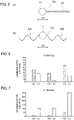
- FIG. 6 is a graph depicting communication distances of experimental RFID tags (A) to (C) or the like for an aircraft tire T (15 inches) according to the present embodiment
- FIG. 7 is a graph depicting communication distances of experimental RFID tags (A) to (C) or the like for the aircraft tire (21 inches) according to a comparative example.
- three experimental RFID tags (A) to (C) with different lengths of the antennas (antenna width) A1 and A2 are prepared as the RFID tag 10 having a dipole antenna illustrated in FIG. 3 .
- a length of antennas (antenna width) of the experimental RFID tag (A) is 60 mm
- a length of the antenna (antenna width) of the experimental RFID tag (B) is 70 mm
- a length of antenna (antenna width) of the experimental RFID tag (C) is 50 mm.
- An aircraft tire (21 inches) as a comparative example and the aircraft tire (15 inches) are prepared, and the RFID tags (A) to (C) are attached to the tire inner surface 102 as illustrated in FIG. 2 such that the antennas A1 and A2 are parallel to the tire circumferential direction D1 or intersect the tire circumferential direction D1 within a predetermined angle range (For example, within 5 degrees), and the communication distance readable by the RFID reader/writer 200 are measured.
- a predetermined angle range For example, within 5 degrees
- the communication distance of the experimental RFID tag (A) is approximately 51 cm
- the communication distance of the experimental RFID tag (B) is approximately 35 cm
- the communication distance of the experimental RFID tag (C) is approximately 69 cm.
- the communication distance of the experimental RFID tag (A) is approximately 17 cm
- the communication distance of the experimental RFID tag (B) is approximately 10 cm
- the communication distance of the experimental RFID tag (C) is approximately 55 cm.
- items (a) to (c) in FIGS. 6 and 7 depict communication distances that are measured in the aircraft tire when the experimental RFID tags (A) to (C) are provided along a width direction of the aircraft tire as a reference.
- the communication distance tends to be longer when the experimental RFID tags (A) to (C) are provided along the circumferential direction than when the experimental RFID tags (A) to (C) are provided along the width direction.
- the communication distance tends to be longer than when RFID tags (A) to (C) are provided along the circumferential direction than when the experimental RFID tags (A) to (C) are provided along the circumferential direction.
- the aircraft tire (15 inches) having relatively small diameter has a longer communication distance than the aircraft tire (21 inches) having a relatively large diameter.
- the aircraft tire T includes an RFID tag 10 having an IC chip 11 configured to store information about the aircraft tire and antennas A1 and A2 extended from the IC chip 11; and the antennas A1 and A2 are disposed such that the antennas A1 and A2 are parallel to the tire circumferential direction D1 or intersects the tire circumferential direction within a predetermined angle range, when the diameter is 15 inches or less, an RFID tag 10 having an antenna with a sufficient length can be disposed without being restricted by the tire width, and the communication performance of the tire improves.
- the belt part 103 disposed in the tread section 106 is made of a non-metal material, attenuation of electromagnetic waves or the like between the RFID tag 10 and the RFID reader/writer 200 reduces, and the communication performance of the tire improves.
- the antenna can be configured of a monopole antenna or a dipole antenna exhibiting a linear shape or wavy line shape, various types of RFID tags can be employed.
- the RFID tag 10 can be attached to the tire inner surface 102, it can be brought close to the bead section 100, and communication property may be further improved by functioning the bead section 100 as an antenna. Further, the sensitivity of the RFID tag 10 can be enhanced by the reflection of the electromagnetic wave by the bead section 100.
- the RFID tag 10 may be disposed to be circumferentially apart from the balance patch provided on the tire inner surface, the RFID tag 10 may be provided in a state where the balance of the aircraft tire T is maintained.
Landscapes
- Engineering & Computer Science (AREA)
- Mechanical Engineering (AREA)
- Computer Hardware Design (AREA)
- Microelectronics & Electronic Packaging (AREA)
- Physics & Mathematics (AREA)
- General Physics & Mathematics (AREA)
- Theoretical Computer Science (AREA)
- Tires In General (AREA)
- Details Of Aerials (AREA)
Abstract
Description
- The present invention relates to an aircraft tire mainly used for an airliner or the like.
- Contactless RFID (Radio Frequency Identification) tags configured to write and read information using electromagnetic waves are widely used.
- An aircraft tire is managed by attaching the RFID tag to the aircraft tire, and writing and reading information related to the tire.
- For example, Patent Literature 1 discloses a structure of an aircraft tire in which the RFID is embedded in a crown region thereof and a dipole antenna is disposed in an axial direction.
- Patent Literature 1:
U.S. Patent Application Publication No. 2011/0226401 - However, in the above-described conventional aircraft tire, when a size (diameter) of the tire is small, for example, 15 inches or less, a length of the antenna in the RFID tag to be disposed in the axial direction is restricted due to a narrow tire width. Therefore, there is a problem that the communication performance with the RFID reader/writer deteriorates.
- An object of the present invention is to provide an aircraft tire that improves RIFD tag communication performance even when a size is 15 inches or smaller.
- One or more embodiments of an aircraft tire (T) according to present invention has a pair of bead sections (100), sidewall sections (104) extending from outer side in a radial direction of the bead sections, and a tread section (106) extending between the sidewall sections; the aircraft tire includes an RFID tag (10) having a tag main body (11) configured to store an information about the aircraft tire and an antenna (A1, A2) extended from the tag main body; wherein, when a diameter size of the aircraft tire is 15 inches or less, in a tread surface view, the antenna is disposed such that the antenna is parallel to a tire circumferential direction or intersects the tire circumferential direction within a predetermined angle range, and a belt part disposed in the tread section is made of non-metal material.
- According to such a configuration, even when the diameter is 15 inches or less, an RFID tag having an antenna with a sufficient length can be disposed without being restricted by the tire width and the communication performance of the tire improves.
- Further, since the belt part disposed in the tread section is made of a non-metal material, attenuation of electromagnetic waves or the like between the RFID tag and the RFID reader/writer reduces, and the communication performance of the tire improves.
- According to the present invention, it is possible to provide an aircraft tire with improved communication performance of an RFID tag even when the size is 15 inches or less.
-
-
FIG. 1 is a cross-sectional view in a tread width direction illustrating a schematic configuration of an aircraft tire according to one or more embodiments. -
FIG. 2 is a perspective view illustrating a schematic configuration of the aircraft tire according to the one or more embodiments. -
FIG. 3 is a schematic configuration diagram illustrating a configuration example of an RFID tag to be applied to the aircraft tire according to the one or more embodiments. -
FIG. 4 is a block diagram illustrating an internal configuration of the RFID tag to be applied to the aircraft tire according to the one or more embodiments. -
FIGS. 5 (a) is a schematic configuration diagram illustrating other configuration examples of RFID tags to be applied to the aircraft tire according to some embodiments. -
FIGS. 5 (b) is a schematic configuration diagram illustrating other configuration examples of RFID tags to be applied to the aircraft tire according to some embodiments. -
FIG. 6 is a graph depicting communication distances of experimental RFID tags (A) to (C) or the like for the aircraft tire (15 inches) according to the embodiments. -
FIG. 7 is a graph depicting communication distances of experimental RFID tags (A) to (C) or the like for an aircraft tire (21 inches) according to comparative examples. - An aircraft tire T according to an embodiment of one or more embodiments will be described with reference to
FIGS. 1 to 7 . - In the following drawings, the same or similar parts are denoted by the same or similar numerals. However, it should be noted that the drawings are schematic, and the ratio of each dimension and the like may be different from the actual figures.
- Therefore, specific dimensions should be determined in consideration of the following description. Further, it is needless to say that portions having different dimensional relationships and ratios among the drawings are included.
- An example of a configuration of an aircraft tire T will be described with reference to
FIGS. 1 and2 . -
FIG. 1 is a cross-sectional view in a tread width direction illustrating a schematic configuration of the aircraft tire T according to one or more embodiments; andFIG. 2 is a perspective view illustrating a schematic configuration of the aircraft tire T. - The aircraft tire T includes
bead sections 100 to be in contact withwheels 150, acarcass 101 as a frame of the aircraft tire T, a plurality ofbelt parts 103 disposed on an outer side in a tire radial direction of thecarcass 101, and atread section 106 disposed on an outer side in the tire radial direction of thebelt part 103 and configured to be in contact with a road surface. Asidewall section 104 extending from an outer side in a radial direction of a pair of thebead sections 100. - As illustrated in
FIG. 1 , a tireinner surface 102 of the aircraft tire T according to the present embodiment is provided with anRFID tag 10 including anIC chip 11 as a tag main body configured to store information (information such as serial number, size, and proper internal pressure) about the aircraft tire T and antennas A1 and A2 extended from theIC chip 11. - More specifically, the
RFID tag 10 is formed by sealing theIC chip 11 and the antennas A1 and A2 within arubber patch 12, and is attached to the tireinner surface 102 by an adhesive. - When the diameter of the aircraft tire T is 15 inches or less, the antennas A1 and A2 are disposed such that the antennas A1 and A2 are parallel to a tire circumferential direction or intersect the tire circumferential direction within a predetermined angle range (For example, within 5 degrees) in the tread surface view, as illustrated in
FIG. 2 . - Further, the
belt part 103 disposed in thetread section 106 is made of a non-metal material such as synthetic fiber. As a result, the attenuation or the like of electromagnetic waves between theRFID tag 10 and the RFID reader/writer 200 reduces, thereby improving the communication performance. - A RFID reader/
writer 200 illustrated inFIG. 1 is configured to transmit and receive information to and from theRFID tag 10. - The RFID reader/
writer 200 includes acommunication antenna 201 and aninformation display part 202 having a liquid crystal display, etc.; and the RFID reader/writer 200 is configured to display and review information (information such as serial number, size, and proper internal pressure) about the aircraft tire T read from theRFID tag 10. - With such a configuration, when the diameter of the aircraft tire T is 21 inches or more, the attenuation of electromagnetic waves in the aircraft tire T reduces and improves the communication performance of the RFID tag. Measurement examples for reviewing the communication performance of the aircraft tire T will be described later.
- When the balance patch is provided on the tire
inner surface 102, theRFID tag 10 is disposed circumferentially apart from the balance patch. Thus, theRFID tag 10 can be provided in a state that the balance of the tire T for the aircraft be maintained. - Further, by attaching the
RFID tag 10 to the tireinner surface 102, thebead section 100 can function as an antenna, and the communication performance is further improved. Moreover, the sensitivity of theRFID tag 10 is enhanced by the reflection of the electromagnetic wave at thebead section 100. - Referring to
FIGS. 3 and 4 , a configuration example of theRFID tag 10 applicable to the aircraft tire T according to the present embodiment will be described. -
FIG. 3 is a schematic configuration diagram illustrating a configuration example of anRFID tag 10 to be applied to the aircraft tire T according to the present embodiment; andFIG. 4 is a block diagram illustrating an internal configuration of theRFID tag 10. - As illustrated in
FIG. 3 , theRFID tag 10 is formed by sealing theIC chip 11 and the antennas A1 and A2 within therubber patch 12. An adhesive layer is provided on a back surface of thepatch 12 so as to be attached to the tireinner surface 102. - As illustrated in
FIG. 4 , theRFID tag 10 includes the antennas A1, A2, a transmitter/receiver (transceiver) 301 including an RF circuit and a power supply circuit, aCPU 302 as a controller, amemory 303 including a nonvolatile memory ROM, and amemory 304 including a volatile memory (RAM). - The antennas A1 and A2 communicate with the RFID reader/
writer 200 and the like. The antennas A1 and A2 also serve as power receiving devices configured to feed electrical power to the transmitter/receiver 301 or the like depending on radio signals from the RFID reader/writer 200 or the like. - The transmitter/
receiver 301 modulates/demodulates data transmitted/received by the RF circuit, and feeds electrical power to theCPU 302 or the like by the power supply circuit. - In accordance with the command received from the antennas A1 and A2, the
CPU 302 performs processing such as responding to data (Serial number, size, proper internal pressure, etc.) about the aircraft tire T or a unique ID recorded in thememory 303. - The
memory 304 is used as a work area of theCPU 302. - Referring to
FIGS. 3 and5 , a configuration example of the antenna in theRFID tag 10 will be described. - Antennas A1 and A2 illustrated in
FIG. 3 are formed to be a so-called dipole antenna in which antenna lines having linear shape and same length (L1, L2) extends from right and left ends of theIC chip 11. The antenna wire may be formed of a coil winding. - The antenna A3 of the
RFID tag 10a illustrated inFIG. 5(a) is a so-called monopole antenna in which an antenna line having a linear shape and having a length L3 extends from a right end of theIC chip 11. The antenna wire may be formed of a coil winding. - The antennas A4a and A4b illustrated in
FIG. 5 (b) are formed to be a so-called dipole antenna in which antenna lines having wavy-line shape extends from the left and right ends of theIC chip 11. - The distances L4 and L5 from the end of the
IC chip 11 to the ends of the antennas A4a and A4b are made the same. - Measurement examples of communication distance of the RFID tags 10 will be described with reference to
FIGS. 6 and 7 . -
FIG. 6 is a graph depicting communication distances of experimental RFID tags (A) to (C) or the like for an aircraft tire T (15 inches) according to the present embodiment; andFIG. 7 is a graph depicting communication distances of experimental RFID tags (A) to (C) or the like for the aircraft tire (21 inches) according to a comparative example. - For measurements, three experimental RFID tags (A) to (C) with different lengths of the antennas (antenna width) A1 and A2 are prepared as the
RFID tag 10 having a dipole antenna illustrated inFIG. 3 . - Here, a length of antennas (antenna width) of the experimental RFID tag (A) is 60 mm, a length of the antenna (antenna width) of the experimental RFID tag (B) is 70 mm, and a length of antenna (antenna width) of the experimental RFID tag (C) is 50 mm.
- An aircraft tire (21 inches) as a comparative example and the aircraft tire (15 inches) are prepared, and the RFID tags (A) to (C) are attached to the tire
inner surface 102 as illustrated inFIG. 2 such that the antennas A1 and A2 are parallel to the tire circumferential direction D1 or intersect the tire circumferential direction D1 within a predetermined angle range (For example, within 5 degrees), and the communication distance readable by the RFID reader/writer 200 are measured. - With the aircraft tire (15 inches), the communication distance of the experimental RFID tag (A) is approximately 51 cm, the communication distance of the experimental RFID tag (B) is approximately 35 cm, and the communication distance of the experimental RFID tag (C) is approximately 69 cm.
- By contrast, with the aircraft tire (21 inches), the communication distance of the experimental RFID tag (A) is approximately 17 cm, the communication distance of the experimental RFID tag (B) is approximately 10 cm, and the communication distance of the experimental RFID tag (C) is approximately 55 cm.
- Note that items (a) to (c) in
FIGS. 6 and 7 depict communication distances that are measured in the aircraft tire when the experimental RFID tags (A) to (C) are provided along a width direction of the aircraft tire as a reference. - According to these graphs, in the case of the aircraft tire (15 inches), the communication distance tends to be longer when the experimental RFID tags (A) to (C) are provided along the circumferential direction than when the experimental RFID tags (A) to (C) are provided along the width direction.
- By contrast, in the case of the aircraft tire (21 inches), the communication distance tends to be longer than when RFID tags (A) to (C) are provided along the circumferential direction than when the experimental RFID tags (A) to (C) are provided along the circumferential direction.
- As described above, when the experimental RFID tags (A) to (C) are attached to the
inner surface 102 such that the antennas A1 and A2 are parallel to the tire circumferential direction D1 or intersect the tire circumferential direction D1 within a predetermined angle range (For example, within 5 degrees), the aircraft tire (15 inches) having relatively small diameter has a longer communication distance than the aircraft tire (21 inches) having a relatively large diameter. - According to the above-described embodiment, the following effects are obtained.
- That is, the aircraft tire T according to the present embodiment includes an
RFID tag 10 having anIC chip 11 configured to store information about the aircraft tire and antennas A1 and A2 extended from theIC chip 11; and the antennas A1 and A2 are disposed such that the antennas A1 and A2 are parallel to the tire circumferential direction D1 or intersects the tire circumferential direction within a predetermined angle range, when the diameter is 15 inches or less, anRFID tag 10 having an antenna with a sufficient length can be disposed without being restricted by the tire width, and the communication performance of the tire improves. - Further, since the
belt part 103 disposed in thetread section 106 is made of a non-metal material, attenuation of electromagnetic waves or the like between theRFID tag 10 and the RFID reader/writer 200 reduces, and the communication performance of the tire improves. - Since the antenna can be configured of a monopole antenna or a dipole antenna exhibiting a linear shape or wavy line shape, various types of RFID tags can be employed.
- Since the
RFID tag 10 can be attached to the tireinner surface 102, it can be brought close to thebead section 100, and communication property may be further improved by functioning thebead section 100 as an antenna. Further, the sensitivity of theRFID tag 10 can be enhanced by the reflection of the electromagnetic wave by thebead section 100. - Since the
RFID tag 10 may be disposed to be circumferentially apart from the balance patch provided on the tire inner surface, theRFID tag 10 may be provided in a state where the balance of the aircraft tire T is maintained. - Although the aircraft tire T of the present invention has been described above based on the illustrated embodiment, the present invention is not limited thereto, and the configuration of each part can be replaced with any configuration having a similar function.
-
- T
- AIRCRAFT TIRE
- A1, A2, A3, A4a, A4b
- ANTENNA
- D1
- EXTENSION DIRECTION
- 10
- RFID TAG
- 11
- TAG MAIN BODY (IC CHIP)
- 100
- BEAD SECTION
- 102
- TIRE INNER SURFACE
- 104
- SIDEWALL SECTION
- 106
- TREAD SECTION
Claims (4)
- An aircraft tire having a pair of bead sections, sidewall sections extending from outer side in a radial direction of the bead sections, and a tread section extending between the sidewall sections, the aircraft tire comprising:an RFID tag comprising: a tag main body configured to store an information about the aircraft tire and an antenna extended from the tag main body, whereinwhen a diameter size of the aircraft tire is 15 inches or less, in a tread surface view, the antenna is disposed such that the antenna is parallel to a tire circumferential direction or intersects the tire circumferential direction within a predetermined angle range, anda belt part disposed in the tread section is made of non-metal material.
- The aircraft tire according to claim 1, wherein the antenna comprises a monopole antenna or a dipole antenna that has a linear shape or wavy line shape.
- The aircraft tire according to claim 1 or 2, wherein the RFID tag is attached to a tire inner surface.
- The aircraft tire according to claim 3, wherein the RFID tag is disposed circumferentially apart form a balance patch provided on the tire inner surface.
Applications Claiming Priority (2)
| Application Number | Priority Date | Filing Date | Title |
|---|---|---|---|
| JP2020025386A JP7457520B2 (en) | 2020-02-18 | 2020-02-18 | aircraft tires |
| PCT/JP2021/005635 WO2021166884A1 (en) | 2020-02-18 | 2021-02-16 | Tire for aircraft |
Publications (3)
| Publication Number | Publication Date |
|---|---|
| EP4108478A1 true EP4108478A1 (en) | 2022-12-28 |
| EP4108478A4 EP4108478A4 (en) | 2023-08-02 |
| EP4108478B1 EP4108478B1 (en) | 2025-12-31 |
Family
ID=77392144
Family Applications (1)
| Application Number | Title | Priority Date | Filing Date |
|---|---|---|---|
| EP21757990.3A Active EP4108478B1 (en) | 2020-02-18 | 2021-02-16 | AIRCRAFT TIRES |
Country Status (4)
| Country | Link |
|---|---|
| US (1) | US12337620B2 (en) |
| EP (1) | EP4108478B1 (en) |
| JP (1) | JP7457520B2 (en) |
| WO (1) | WO2021166884A1 (en) |
Family Cites Families (16)
| Publication number | Priority date | Publication date | Assignee | Title |
|---|---|---|---|---|
| KR100565029B1 (en) * | 1999-02-11 | 2006-03-30 | 미쉐린 러쉐르슈 에 떼크니크 에스.에이. | Monitored Car Tires and Monitor Retainer Assemblies |
| US7091841B2 (en) * | 2003-02-19 | 2006-08-15 | Michelin Recherche Et Technique, S.A. | Tire electronics assembly having a multi-frequency antenna |
| DE60335830D1 (en) | 2003-02-19 | 2011-03-03 | Michelin Soc Tech | TIRE ELECTRONICS WITH A MULTI FREQUENCY ANTENNA |
| US7186308B2 (en) * | 2003-10-09 | 2007-03-06 | Michelin Recherche Et Technique S.A. | System and method for providing tire electronics mounting patches |
| EP1674301A3 (en) * | 2004-12-23 | 2010-04-28 | Société de Technologie Michelin | System for wireless data communication between a vehicle and its tires |
| DE102005005221A1 (en) | 2005-02-03 | 2006-08-10 | Continental Aktiengesellschaft | vehicle tires |
| JP2006335031A (en) * | 2005-06-06 | 2006-12-14 | Yokohama Rubber Co Ltd:The | Mold for retread tire, method for manufacturing retread tire, and retread tire |
| US7468655B2 (en) * | 2006-08-25 | 2008-12-23 | The Goodyear Tire & Rubber Company | Aircraft tire condition monitoring system and method |
| EP2039536A1 (en) | 2007-09-18 | 2009-03-25 | Carnehammar, Lars Bertil | Method, apparatus and system for processing of vehicle tyres |
| JP2010269670A (en) * | 2009-05-20 | 2010-12-02 | Bridgestone Corp | Radio communication device and tire including the same |
| JP5421662B2 (en) * | 2009-06-10 | 2014-02-19 | 株式会社ブリヂストン | WIRELESS COMMUNICATION DEVICE AND PNEUMATIC TIRE HAVING WIRELESS COMMUNICATION DEVICE |
| FR2956616A1 (en) * | 2010-02-23 | 2011-08-26 | Michelin Soc Tech | PNEUMATIC COMPRISING AN ELECTRONIC MEMBER |
| US10336144B2 (en) * | 2014-12-30 | 2019-07-02 | Bridgestone Americas Tire Operations, Llc | Tire electronics securing structures |
| JP6612141B2 (en) * | 2016-01-25 | 2019-11-27 | 株式会社ブリヂストン | RFID tag built-in tire |
| EP3981614A1 (en) * | 2019-06-05 | 2022-04-13 | Sumitomo Rubber Industries, Ltd. | Cord and tire |
| JP7457519B2 (en) * | 2020-02-18 | 2024-03-28 | 株式会社ブリヂストン | aircraft tires |
-
2020
- 2020-02-18 JP JP2020025386A patent/JP7457520B2/en active Active
-
2021
- 2021-02-16 WO PCT/JP2021/005635 patent/WO2021166884A1/en not_active Ceased
- 2021-02-16 US US17/800,159 patent/US12337620B2/en active Active
- 2021-02-16 EP EP21757990.3A patent/EP4108478B1/en active Active
Also Published As
| Publication number | Publication date |
|---|---|
| EP4108478A4 (en) | 2023-08-02 |
| JP2021130345A (en) | 2021-09-09 |
| WO2021166884A1 (en) | 2021-08-26 |
| EP4108478B1 (en) | 2025-12-31 |
| US20230074848A1 (en) | 2023-03-09 |
| US12337620B2 (en) | 2025-06-24 |
| JP7457520B2 (en) | 2024-03-28 |
Similar Documents
| Publication | Publication Date | Title |
|---|---|---|
| EP4108477B1 (en) | Aircraft tire | |
| CN101878479B (en) | Metallic pipe managed by wireless ic tag, and the wireless ic tag | |
| US7916095B2 (en) | Wave antenna wireless communication device and method | |
| JP6612141B2 (en) | RFID tag built-in tire | |
| US7573388B2 (en) | RFID device with augmented grain | |
| KR100630823B1 (en) | Radio wave identification tag device for tire in radio wave identification system | |
| CN101728647A (en) | Small-sized radio-frequency identification label and micro-strip patch antenna therein | |
| US20120249306A1 (en) | Rf-id tag and rf-id communication system | |
| US11984656B2 (en) | RF tag antenna, RF tag, tire provided with RF tag, and tire with built-in RF tag | |
| KR101126672B1 (en) | Metal tag antena | |
| EP4108478B1 (en) | AIRCRAFT TIRES | |
| US20100230499A1 (en) | Rfid tag for metallic materials | |
| KR100763596B1 (en) | Antenna using loop structure and helical structure, RDF tag and antenna impedance matching method | |
| JP2021002254A (en) | Rf tag label and rf tag label attached rubber-based product | |
| KR101989832B1 (en) | Ultrafine conductive fiber RFID tag antenna | |
| WO2020075469A1 (en) | Rf tag label and rubber product equipped with rf tag label | |
| JP6930776B2 (en) | RF tag antenna and RF tag, RF tag sponge member, RF tag silent tire, RF tag tire | |
| CN201655968U (en) | Ultrahigh frequency radio frequency identification tag antenna | |
| JP4743434B2 (en) | Non-contact IC tag | |
| WO2016049844A1 (en) | Radio frequency identification (rfid) tag | |
| JP2008134867A (en) | Non-contact IC tag | |
| CN221175433U (en) | Liquid-resistant and metal-resistant ultrahigh frequency tag | |
| KR100862477B1 (en) | RFID tag | |
| US7542003B2 (en) | Contactless label with Y-shaped omnidirectional antenna | |
| SE1950795A1 (en) | A UHF RFID tag |
Legal Events
| Date | Code | Title | Description |
|---|---|---|---|
| STAA | Information on the status of an ep patent application or granted ep patent |
Free format text: STATUS: THE INTERNATIONAL PUBLICATION HAS BEEN MADE |
|
| PUAI | Public reference made under article 153(3) epc to a published international application that has entered the european phase |
Free format text: ORIGINAL CODE: 0009012 |
|
| STAA | Information on the status of an ep patent application or granted ep patent |
Free format text: STATUS: REQUEST FOR EXAMINATION WAS MADE |
|
| 17P | Request for examination filed |
Effective date: 20220916 |
|
| AK | Designated contracting states |
Kind code of ref document: A1 Designated state(s): AL AT BE BG CH CY CZ DE DK EE ES FI FR GB GR HR HU IE IS IT LI LT LU LV MC MK MT NL NO PL PT RO RS SE SI SK SM TR |
|
| DAV | Request for validation of the european patent (deleted) | ||
| DAX | Request for extension of the european patent (deleted) | ||
| A4 | Supplementary search report drawn up and despatched |
Effective date: 20230703 |
|
| RIC1 | Information provided on ipc code assigned before grant |
Ipc: G06K 19/077 20060101ALI20230627BHEP Ipc: B60C 9/20 20060101ALI20230627BHEP Ipc: B60C 9/18 20060101ALI20230627BHEP Ipc: B60C 19/00 20060101AFI20230627BHEP |
|
| STAA | Information on the status of an ep patent application or granted ep patent |
Free format text: STATUS: EXAMINATION IS IN PROGRESS |
|
| 17Q | First examination report despatched |
Effective date: 20240724 |
|
| GRAP | Despatch of communication of intention to grant a patent |
Free format text: ORIGINAL CODE: EPIDOSNIGR1 |
|
| STAA | Information on the status of an ep patent application or granted ep patent |
Free format text: STATUS: GRANT OF PATENT IS INTENDED |
|
| INTG | Intention to grant announced |
Effective date: 20251001 |
|
| GRAS | Grant fee paid |
Free format text: ORIGINAL CODE: EPIDOSNIGR3 |
|
| GRAA | (expected) grant |
Free format text: ORIGINAL CODE: 0009210 |
|
| STAA | Information on the status of an ep patent application or granted ep patent |
Free format text: STATUS: THE PATENT HAS BEEN GRANTED |
|
| AK | Designated contracting states |
Kind code of ref document: B1 Designated state(s): AL AT BE BG CH CY CZ DE DK EE ES FI FR GB GR HR HU IE IS IT LI LT LU LV MC MK MT NL NO PL PT RO RS SE SI SK SM TR |
|
| REG | Reference to a national code |
Ref country code: CH Ref legal event code: F10 Free format text: ST27 STATUS EVENT CODE: U-0-0-F10-F00 (AS PROVIDED BY THE NATIONAL OFFICE) Effective date: 20251231 Ref country code: GB Ref legal event code: FG4D |
|
| P01 | Opt-out of the competence of the unified patent court (upc) registered |
Free format text: CASE NUMBER: UPC_APP_0016255_4108478/2025 Effective date: 20251208 |
|
| REG | Reference to a national code |
Ref country code: DE Ref legal event code: R096 Ref document number: 602021045480 Country of ref document: DE |
|
| REG | Reference to a national code |
Ref country code: IE Ref legal event code: FG4D |
|
| REG | Reference to a national code |
Ref country code: LT Ref legal event code: MG9D |
|
| PG25 | Lapsed in a contracting state [announced via postgrant information from national office to epo] |
Ref country code: NO Free format text: LAPSE BECAUSE OF FAILURE TO SUBMIT A TRANSLATION OF THE DESCRIPTION OR TO PAY THE FEE WITHIN THE PRESCRIBED TIME-LIMIT Effective date: 20260331 |
|
| PGFP | Annual fee paid to national office [announced via postgrant information from national office to epo] |
Ref country code: DE Payment date: 20260218 Year of fee payment: 6 |
|
| PG25 | Lapsed in a contracting state [announced via postgrant information from national office to epo] |
Ref country code: FI Free format text: LAPSE BECAUSE OF FAILURE TO SUBMIT A TRANSLATION OF THE DESCRIPTION OR TO PAY THE FEE WITHIN THE PRESCRIBED TIME-LIMIT Effective date: 20251231 Ref country code: HR Free format text: LAPSE BECAUSE OF FAILURE TO SUBMIT A TRANSLATION OF THE DESCRIPTION OR TO PAY THE FEE WITHIN THE PRESCRIBED TIME-LIMIT Effective date: 20251231 |
|
| PG25 | Lapsed in a contracting state [announced via postgrant information from national office to epo] |
Ref country code: RS Free format text: LAPSE BECAUSE OF FAILURE TO SUBMIT A TRANSLATION OF THE DESCRIPTION OR TO PAY THE FEE WITHIN THE PRESCRIBED TIME-LIMIT Effective date: 20260331 |
|
| PGFP | Annual fee paid to national office [announced via postgrant information from national office to epo] |
Ref country code: FR Payment date: 20260219 Year of fee payment: 6 |
|
| PG25 | Lapsed in a contracting state [announced via postgrant information from national office to epo] |
Ref country code: LV Free format text: LAPSE BECAUSE OF FAILURE TO SUBMIT A TRANSLATION OF THE DESCRIPTION OR TO PAY THE FEE WITHIN THE PRESCRIBED TIME-LIMIT Effective date: 20251231 |
|
| PG25 | Lapsed in a contracting state [announced via postgrant information from national office to epo] |
Ref country code: BG Free format text: LAPSE BECAUSE OF FAILURE TO SUBMIT A TRANSLATION OF THE DESCRIPTION OR TO PAY THE FEE WITHIN THE PRESCRIBED TIME-LIMIT Effective date: 20251231 |
|
| REG | Reference to a national code |
Ref country code: NL Ref legal event code: MP Effective date: 20251231 |
|
| REG | Reference to a national code |
Ref country code: AT Ref legal event code: MK05 Ref document number: 1872846 Country of ref document: AT Kind code of ref document: T Effective date: 20251231 |
|
| PG25 | Lapsed in a contracting state [announced via postgrant information from national office to epo] |
Ref country code: NL Free format text: LAPSE BECAUSE OF FAILURE TO SUBMIT A TRANSLATION OF THE DESCRIPTION OR TO PAY THE FEE WITHIN THE PRESCRIBED TIME-LIMIT Effective date: 20251231 |
|
| PG25 | Lapsed in a contracting state [announced via postgrant information from national office to epo] |
Ref country code: LT Free format text: LAPSE BECAUSE OF FAILURE TO SUBMIT A TRANSLATION OF THE DESCRIPTION OR TO PAY THE FEE WITHIN THE PRESCRIBED TIME-LIMIT Effective date: 20251231 |
|
| PG25 | Lapsed in a contracting state [announced via postgrant information from national office to epo] |
Ref country code: SM Free format text: LAPSE BECAUSE OF FAILURE TO SUBMIT A TRANSLATION OF THE DESCRIPTION OR TO PAY THE FEE WITHIN THE PRESCRIBED TIME-LIMIT Effective date: 20251231 |
|
| PG25 | Lapsed in a contracting state [announced via postgrant information from national office to epo] |
Ref country code: ES Free format text: LAPSE BECAUSE OF FAILURE TO SUBMIT A TRANSLATION OF THE DESCRIPTION OR TO PAY THE FEE WITHIN THE PRESCRIBED TIME-LIMIT Effective date: 20251231 |
|
| PG25 | Lapsed in a contracting state [announced via postgrant information from national office to epo] |
Ref country code: PL Free format text: LAPSE BECAUSE OF FAILURE TO SUBMIT A TRANSLATION OF THE DESCRIPTION OR TO PAY THE FEE WITHIN THE PRESCRIBED TIME-LIMIT Effective date: 20251231 |
|
| PG25 | Lapsed in a contracting state [announced via postgrant information from national office to epo] |
Ref country code: IT Free format text: LAPSE BECAUSE OF FAILURE TO SUBMIT A TRANSLATION OF THE DESCRIPTION OR TO PAY THE FEE WITHIN THE PRESCRIBED TIME-LIMIT Effective date: 20251231 |
|
| PG25 | Lapsed in a contracting state [announced via postgrant information from national office to epo] |
Ref country code: AT Free format text: LAPSE BECAUSE OF FAILURE TO SUBMIT A TRANSLATION OF THE DESCRIPTION OR TO PAY THE FEE WITHIN THE PRESCRIBED TIME-LIMIT Effective date: 20251231 |
|
| PG25 | Lapsed in a contracting state [announced via postgrant information from national office to epo] |
Ref country code: EE Free format text: LAPSE BECAUSE OF FAILURE TO SUBMIT A TRANSLATION OF THE DESCRIPTION OR TO PAY THE FEE WITHIN THE PRESCRIBED TIME-LIMIT Effective date: 20251231 |
|
| PG25 | Lapsed in a contracting state [announced via postgrant information from national office to epo] |
Ref country code: PT Free format text: LAPSE BECAUSE OF FAILURE TO SUBMIT A TRANSLATION OF THE DESCRIPTION OR TO PAY THE FEE WITHIN THE PRESCRIBED TIME-LIMIT Effective date: 20260430 Ref country code: IS Free format text: LAPSE BECAUSE OF FAILURE TO SUBMIT A TRANSLATION OF THE DESCRIPTION OR TO PAY THE FEE WITHIN THE PRESCRIBED TIME-LIMIT Effective date: 20260430 |
|
| PG25 | Lapsed in a contracting state [announced via postgrant information from national office to epo] |
Ref country code: CZ Free format text: LAPSE BECAUSE OF FAILURE TO SUBMIT A TRANSLATION OF THE DESCRIPTION OR TO PAY THE FEE WITHIN THE PRESCRIBED TIME-LIMIT Effective date: 20251231 |
|
| PG25 | Lapsed in a contracting state [announced via postgrant information from national office to epo] |
Ref country code: SK Free format text: LAPSE BECAUSE OF FAILURE TO SUBMIT A TRANSLATION OF THE DESCRIPTION OR TO PAY THE FEE WITHIN THE PRESCRIBED TIME-LIMIT Effective date: 20251231 |
|
| PG25 | Lapsed in a contracting state [announced via postgrant information from national office to epo] |
Ref country code: SE Free format text: LAPSE BECAUSE OF FAILURE TO SUBMIT A TRANSLATION OF THE DESCRIPTION OR TO PAY THE FEE WITHIN THE PRESCRIBED TIME-LIMIT Effective date: 20251231 |