EP4108429A1 - Battery case molding apparatus using shock wave, and battery case molding method using same - Google Patents
Battery case molding apparatus using shock wave, and battery case molding method using same Download PDFInfo
- Publication number
- EP4108429A1 EP4108429A1 EP21886636.6A EP21886636A EP4108429A1 EP 4108429 A1 EP4108429 A1 EP 4108429A1 EP 21886636 A EP21886636 A EP 21886636A EP 4108429 A1 EP4108429 A1 EP 4108429A1
- Authority
- EP
- European Patent Office
- Prior art keywords
- punch
- battery case
- laminate sheet
- conductive liquid
- elastic separator
- Prior art date
- Legal status (The legal status is an assumption and is not a legal conclusion. Google has not performed a legal analysis and makes no representation as to the accuracy of the status listed.)
- Granted
Links
Images



Classifications
-
- B—PERFORMING OPERATIONS; TRANSPORTING
- B29—WORKING OF PLASTICS; WORKING OF SUBSTANCES IN A PLASTIC STATE IN GENERAL
- B29C—SHAPING OR JOINING OF PLASTICS; SHAPING OF MATERIAL IN A PLASTIC STATE, NOT OTHERWISE PROVIDED FOR; AFTER-TREATMENT OF THE SHAPED PRODUCTS, e.g. REPAIRING
- B29C67/00—Shaping techniques not covered by groups B29C39/00 - B29C65/00, B29C70/00 or B29C73/00
- B29C67/0033—Shaping techniques not covered by groups B29C39/00 - B29C65/00, B29C70/00 or B29C73/00 by shock-waves
-
- B—PERFORMING OPERATIONS; TRANSPORTING
- B21—MECHANICAL METAL-WORKING WITHOUT ESSENTIALLY REMOVING MATERIAL; PUNCHING METAL
- B21D—WORKING OR PROCESSING OF SHEET METAL OR METAL TUBES, RODS OR PROFILES WITHOUT ESSENTIALLY REMOVING MATERIAL; PUNCHING METAL
- B21D26/00—Shaping without cutting otherwise than using rigid devices or tools or yieldable or resilient pads, i.e. applying fluid pressure or magnetic forces
- B21D26/02—Shaping without cutting otherwise than using rigid devices or tools or yieldable or resilient pads, i.e. applying fluid pressure or magnetic forces by applying fluid pressure
- B21D26/06—Shaping without cutting otherwise than using rigid devices or tools or yieldable or resilient pads, i.e. applying fluid pressure or magnetic forces by applying fluid pressure by shock waves
- B21D26/12—Shaping without cutting otherwise than using rigid devices or tools or yieldable or resilient pads, i.e. applying fluid pressure or magnetic forces by applying fluid pressure by shock waves initiated by spark discharge
-
- H—ELECTRICITY
- H01—ELECTRIC ELEMENTS
- H01M—PROCESSES OR MEANS, e.g. BATTERIES, FOR THE DIRECT CONVERSION OF CHEMICAL ENERGY INTO ELECTRICAL ENERGY
- H01M50/00—Constructional details or processes of manufacture of the non-active parts of electrochemical cells other than fuel cells, e.g. hybrid cells
- H01M50/10—Primary casings; Jackets or wrappings
- H01M50/102—Primary casings; Jackets or wrappings characterised by their shape or physical structure
- H01M50/105—Pouches or flexible bags
-
- B—PERFORMING OPERATIONS; TRANSPORTING
- B21—MECHANICAL METAL-WORKING WITHOUT ESSENTIALLY REMOVING MATERIAL; PUNCHING METAL
- B21D—WORKING OR PROCESSING OF SHEET METAL OR METAL TUBES, RODS OR PROFILES WITHOUT ESSENTIALLY REMOVING MATERIAL; PUNCHING METAL
- B21D22/00—Shaping without cutting, by stamping, spinning, or deep-drawing
- B21D22/20—Deep-drawing
- B21D22/30—Deep-drawing to finish articles formed by deep-drawing
-
- B—PERFORMING OPERATIONS; TRANSPORTING
- B21—MECHANICAL METAL-WORKING WITHOUT ESSENTIALLY REMOVING MATERIAL; PUNCHING METAL
- B21D—WORKING OR PROCESSING OF SHEET METAL OR METAL TUBES, RODS OR PROFILES WITHOUT ESSENTIALLY REMOVING MATERIAL; PUNCHING METAL
- B21D26/00—Shaping without cutting otherwise than using rigid devices or tools or yieldable or resilient pads, i.e. applying fluid pressure or magnetic forces
- B21D26/02—Shaping without cutting otherwise than using rigid devices or tools or yieldable or resilient pads, i.e. applying fluid pressure or magnetic forces by applying fluid pressure
- B21D26/06—Shaping without cutting otherwise than using rigid devices or tools or yieldable or resilient pads, i.e. applying fluid pressure or magnetic forces by applying fluid pressure by shock waves
-
- B—PERFORMING OPERATIONS; TRANSPORTING
- B29—WORKING OF PLASTICS; WORKING OF SUBSTANCES IN A PLASTIC STATE IN GENERAL
- B29C—SHAPING OR JOINING OF PLASTICS; SHAPING OF MATERIAL IN A PLASTIC STATE, NOT OTHERWISE PROVIDED FOR; AFTER-TREATMENT OF THE SHAPED PRODUCTS, e.g. REPAIRING
- B29C33/00—Moulds or cores; Details thereof or accessories therefor
- B29C33/20—Opening, closing or clamping
- B29C33/202—Clamping means operating on closed or nearly closed mould parts, the clamping means being independently movable of the opening or closing means
-
- B—PERFORMING OPERATIONS; TRANSPORTING
- B29—WORKING OF PLASTICS; WORKING OF SUBSTANCES IN A PLASTIC STATE IN GENERAL
- B29C—SHAPING OR JOINING OF PLASTICS; SHAPING OF MATERIAL IN A PLASTIC STATE, NOT OTHERWISE PROVIDED FOR; AFTER-TREATMENT OF THE SHAPED PRODUCTS, e.g. REPAIRING
- B29C43/00—Compression moulding, i.e. applying external pressure to flow the moulding material; Apparatus therefor
- B29C43/32—Component parts, details or accessories; Auxiliary operations
-
- B—PERFORMING OPERATIONS; TRANSPORTING
- B29—WORKING OF PLASTICS; WORKING OF SUBSTANCES IN A PLASTIC STATE IN GENERAL
- B29C—SHAPING OR JOINING OF PLASTICS; SHAPING OF MATERIAL IN A PLASTIC STATE, NOT OTHERWISE PROVIDED FOR; AFTER-TREATMENT OF THE SHAPED PRODUCTS, e.g. REPAIRING
- B29C43/00—Compression moulding, i.e. applying external pressure to flow the moulding material; Apparatus therefor
- B29C43/32—Component parts, details or accessories; Auxiliary operations
- B29C43/36—Moulds for making articles of definite length, i.e. discrete articles
- B29C43/3642—Bags, bleeder sheets or cauls for isostatic pressing
-
- B—PERFORMING OPERATIONS; TRANSPORTING
- B29—WORKING OF PLASTICS; WORKING OF SUBSTANCES IN A PLASTIC STATE IN GENERAL
- B29C—SHAPING OR JOINING OF PLASTICS; SHAPING OF MATERIAL IN A PLASTIC STATE, NOT OTHERWISE PROVIDED FOR; AFTER-TREATMENT OF THE SHAPED PRODUCTS, e.g. REPAIRING
- B29C51/00—Shaping by thermoforming, i.e. shaping sheets or sheet like preforms after heating, e.g. shaping sheets in matched moulds or by deep-drawing; Apparatus therefor
- B29C51/08—Deep drawing or matched-mould forming, i.e. using mechanical means only
-
- B—PERFORMING OPERATIONS; TRANSPORTING
- B29—WORKING OF PLASTICS; WORKING OF SUBSTANCES IN A PLASTIC STATE IN GENERAL
- B29C—SHAPING OR JOINING OF PLASTICS; SHAPING OF MATERIAL IN A PLASTIC STATE, NOT OTHERWISE PROVIDED FOR; AFTER-TREATMENT OF THE SHAPED PRODUCTS, e.g. REPAIRING
- B29C51/00—Shaping by thermoforming, i.e. shaping sheets or sheet like preforms after heating, e.g. shaping sheets in matched moulds or by deep-drawing; Apparatus therefor
- B29C51/26—Component parts, details or accessories; Auxiliary operations
- B29C51/261—Handling means, e.g. transfer means, feeding means
- B29C51/262—Clamping means for the sheets, e.g. clamping frames
-
- B—PERFORMING OPERATIONS; TRANSPORTING
- B29—WORKING OF PLASTICS; WORKING OF SUBSTANCES IN A PLASTIC STATE IN GENERAL
- B29C—SHAPING OR JOINING OF PLASTICS; SHAPING OF MATERIAL IN A PLASTIC STATE, NOT OTHERWISE PROVIDED FOR; AFTER-TREATMENT OF THE SHAPED PRODUCTS, e.g. REPAIRING
- B29C69/00—Combinations of shaping techniques not provided for in a single one of main groups B29C39/00 - B29C67/00, e.g. associations of moulding and joining techniques; Apparatus therefore
- B29C69/02—Combinations of shaping techniques not provided for in a single one of main groups B29C39/00 - B29C67/00, e.g. associations of moulding and joining techniques; Apparatus therefore of moulding techniques only
-
- H—ELECTRICITY
- H01—ELECTRIC ELEMENTS
- H01M—PROCESSES OR MEANS, e.g. BATTERIES, FOR THE DIRECT CONVERSION OF CHEMICAL ENERGY INTO ELECTRICAL ENERGY
- H01M10/00—Secondary cells; Manufacture thereof
- H01M10/04—Construction or manufacture in general
- H01M10/0404—Machines for assembling batteries
-
- H—ELECTRICITY
- H01—ELECTRIC ELEMENTS
- H01M—PROCESSES OR MEANS, e.g. BATTERIES, FOR THE DIRECT CONVERSION OF CHEMICAL ENERGY INTO ELECTRICAL ENERGY
- H01M10/00—Secondary cells; Manufacture thereof
- H01M10/05—Accumulators with non-aqueous electrolyte
- H01M10/058—Construction or manufacture
-
- H—ELECTRICITY
- H01—ELECTRIC ELEMENTS
- H01M—PROCESSES OR MEANS, e.g. BATTERIES, FOR THE DIRECT CONVERSION OF CHEMICAL ENERGY INTO ELECTRICAL ENERGY
- H01M50/00—Constructional details or processes of manufacture of the non-active parts of electrochemical cells other than fuel cells, e.g. hybrid cells
- H01M50/10—Primary casings; Jackets or wrappings
- H01M50/102—Primary casings; Jackets or wrappings characterised by their shape or physical structure
- H01M50/103—Primary casings; Jackets or wrappings characterised by their shape or physical structure prismatic or rectangular
-
- H—ELECTRICITY
- H01—ELECTRIC ELEMENTS
- H01M—PROCESSES OR MEANS, e.g. BATTERIES, FOR THE DIRECT CONVERSION OF CHEMICAL ENERGY INTO ELECTRICAL ENERGY
- H01M50/00—Constructional details or processes of manufacture of the non-active parts of electrochemical cells other than fuel cells, e.g. hybrid cells
- H01M50/10—Primary casings; Jackets or wrappings
- H01M50/116—Primary casings; Jackets or wrappings characterised by the material
- H01M50/124—Primary casings; Jackets or wrappings characterised by the material having a layered structure
-
- H—ELECTRICITY
- H01—ELECTRIC ELEMENTS
- H01M—PROCESSES OR MEANS, e.g. BATTERIES, FOR THE DIRECT CONVERSION OF CHEMICAL ENERGY INTO ELECTRICAL ENERGY
- H01M50/00—Constructional details or processes of manufacture of the non-active parts of electrochemical cells other than fuel cells, e.g. hybrid cells
- H01M50/10—Primary casings; Jackets or wrappings
- H01M50/131—Primary casings; Jackets or wrappings characterised by physical properties, e.g. gas permeability, size or heat resistance
- H01M50/133—Thickness
-
- B—PERFORMING OPERATIONS; TRANSPORTING
- B29—WORKING OF PLASTICS; WORKING OF SUBSTANCES IN A PLASTIC STATE IN GENERAL
- B29C—SHAPING OR JOINING OF PLASTICS; SHAPING OF MATERIAL IN A PLASTIC STATE, NOT OTHERWISE PROVIDED FOR; AFTER-TREATMENT OF THE SHAPED PRODUCTS, e.g. REPAIRING
- B29C33/00—Moulds or cores; Details thereof or accessories therefor
- B29C33/20—Opening, closing or clamping
- B29C33/202—Clamping means operating on closed or nearly closed mould parts, the clamping means being independently movable of the opening or closing means
- B29C2033/205—Clamping means operating on closed or nearly closed mould parts, the clamping means being independently movable of the opening or closing means mould clamping by membranes, e.g. inflatable membranes or cushions
-
- B—PERFORMING OPERATIONS; TRANSPORTING
- B29—WORKING OF PLASTICS; WORKING OF SUBSTANCES IN A PLASTIC STATE IN GENERAL
- B29C—SHAPING OR JOINING OF PLASTICS; SHAPING OF MATERIAL IN A PLASTIC STATE, NOT OTHERWISE PROVIDED FOR; AFTER-TREATMENT OF THE SHAPED PRODUCTS, e.g. REPAIRING
- B29C43/00—Compression moulding, i.e. applying external pressure to flow the moulding material; Apparatus therefor
- B29C43/32—Component parts, details or accessories; Auxiliary operations
- B29C2043/3205—Particular pressure exerting means for making definite articles
-
- B—PERFORMING OPERATIONS; TRANSPORTING
- B29—WORKING OF PLASTICS; WORKING OF SUBSTANCES IN A PLASTIC STATE IN GENERAL
- B29C—SHAPING OR JOINING OF PLASTICS; SHAPING OF MATERIAL IN A PLASTIC STATE, NOT OTHERWISE PROVIDED FOR; AFTER-TREATMENT OF THE SHAPED PRODUCTS, e.g. REPAIRING
- B29C43/00—Compression moulding, i.e. applying external pressure to flow the moulding material; Apparatus therefor
- B29C43/32—Component parts, details or accessories; Auxiliary operations
- B29C2043/3205—Particular pressure exerting means for making definite articles
- B29C2043/3266—Particular pressure exerting means for making definite articles vibrating tool means
-
- B—PERFORMING OPERATIONS; TRANSPORTING
- B29—WORKING OF PLASTICS; WORKING OF SUBSTANCES IN A PLASTIC STATE IN GENERAL
- B29C—SHAPING OR JOINING OF PLASTICS; SHAPING OF MATERIAL IN A PLASTIC STATE, NOT OTHERWISE PROVIDED FOR; AFTER-TREATMENT OF THE SHAPED PRODUCTS, e.g. REPAIRING
- B29C43/00—Compression moulding, i.e. applying external pressure to flow the moulding material; Apparatus therefor
- B29C43/32—Component parts, details or accessories; Auxiliary operations
- B29C43/36—Moulds for making articles of definite length, i.e. discrete articles
- B29C43/361—Moulds for making articles of definite length, i.e. discrete articles with pressing members independently movable of the parts for opening or closing the mould, e.g. movable pistons
- B29C2043/3615—Forming elements, e.g. mandrels or rams or stampers or pistons or plungers or punching devices
-
- B—PERFORMING OPERATIONS; TRANSPORTING
- B29—WORKING OF PLASTICS; WORKING OF SUBSTANCES IN A PLASTIC STATE IN GENERAL
- B29C—SHAPING OR JOINING OF PLASTICS; SHAPING OF MATERIAL IN A PLASTIC STATE, NOT OTHERWISE PROVIDED FOR; AFTER-TREATMENT OF THE SHAPED PRODUCTS, e.g. REPAIRING
- B29C43/00—Compression moulding, i.e. applying external pressure to flow the moulding material; Apparatus therefor
- B29C43/32—Component parts, details or accessories; Auxiliary operations
- B29C43/36—Moulds for making articles of definite length, i.e. discrete articles
- B29C43/3642—Bags, bleeder sheets or cauls for isostatic pressing
- B29C2043/3652—Elastic moulds or mould parts, e.g. cores or inserts
-
- B—PERFORMING OPERATIONS; TRANSPORTING
- B29—WORKING OF PLASTICS; WORKING OF SUBSTANCES IN A PLASTIC STATE IN GENERAL
- B29L—INDEXING SCHEME ASSOCIATED WITH SUBCLASS B29C, RELATING TO PARTICULAR ARTICLES
- B29L2031/00—Other particular articles
- B29L2031/712—Containers; Packaging elements or accessories, Packages
- B29L2031/7146—Battery-cases
-
- Y—GENERAL TAGGING OF NEW TECHNOLOGICAL DEVELOPMENTS; GENERAL TAGGING OF CROSS-SECTIONAL TECHNOLOGIES SPANNING OVER SEVERAL SECTIONS OF THE IPC; TECHNICAL SUBJECTS COVERED BY FORMER USPC CROSS-REFERENCE ART COLLECTIONS [XRACs] AND DIGESTS
- Y02—TECHNOLOGIES OR APPLICATIONS FOR MITIGATION OR ADAPTATION AGAINST CLIMATE CHANGE
- Y02E—REDUCTION OF GREENHOUSE GAS [GHG] EMISSIONS, RELATED TO ENERGY GENERATION, TRANSMISSION OR DISTRIBUTION
- Y02E60/00—Enabling technologies; Technologies with a potential or indirect contribution to GHG emissions mitigation
- Y02E60/10—Energy storage using batteries
Definitions
- the present invention relates to a battery case shaping apparatus using a shock wave and a battery case shaping method using the same. More particularly, the present invention relates to a battery case shaping apparatus using a shock wave capable of reducing friction between a punch and a die and extending an elongation range of a laminate sheet in a process of shaping a pouch-shaped battery case, thereby improving shapeability of the battery case, and a battery case shaping method using the same.
- the lithium secondary battery may be classified as a cylindrical secondary battery made of a metal material, a prismatic secondary battery made of a metal material, or a pouch-shaped secondary battery made of a laminate sheet.
- the pouch-shaped secondary battery has advantages in that the pouch-shaped secondary battery is stacked with high degree of integration, thereby having high energy density per unit weight, is manufactured at low cost, and is easily deformable. Consequently, the pouch-shaped secondary battery is used in various devices.
- the pouch-shaped secondary battery uses a laminate sheet including an outer coating layer, a metal blocking layer, and an inner adhesive layer as a battery case, and is configured to have a structure in which an electrode assembly is received in a receiving portion formed in the laminate sheet together with an electrolytic solution.
- a deep drawing method of disposing a laminate sheet on a die, fixing the laminated sheet using a holder, and pressing the laminate sheet using a punch is used.
- external defects such as pinholes or cracks, are formed on the outer surface of the laminate sheet due to limited ductility of the laminate sheet and the force of friction between the punch and the laminate sheet.
- Patent Document 1 discloses technology capable of pressing using pressure of liquid in a punch of a press apparatus, which includes the punch, a blank holder, and a die, and generating a pressure wave in the liquid through two electrodes to form a sheet.
- Patent Document 1 in which an outer wall of the punch contacts the die, cannot solve a problem in that the sheet is locally elongated in a process of shaping the sheet.
- Patent Document 1 US Patent Application Publication No. 2015-0360275 (2015.12.17 )
- the present invention has been made in view of the above problems, and it is an object of the present invention to provide a battery case shaping apparatus capable of reducing the force of friction between a punch configured to press a laminate sheet in order to shape a battery case and the laminate sheet due to contact therebetween, thereby preventing damage to the laminate sheet, and a battery case shaping method using the same.
- a battery case shaping apparatus includes a punch configured to press a laminate sheet for battery cases, a die located under the punch, the die forming an accommodation portion corresponding to an electrode assembly receiving portion, a holder configured to fix the laminate sheet, an elastic separator coupled to the holder, the elastic separator being located under the punch, a conductive liquid configured to form a cavity due to gas generated by electric discharge, and a positive electrode and a negative electrode each disposed in contact with the conductive liquid for the electric discharge.
- a space may be defined by the elastic separator, the holder, to which the elastic separator is coupled, and the lower surface of the punch, and the conductive liquid may be received in the space.
- a sealing member may be added to a contacting surface of the holder that contacts the punch, the contacting surface being among outer surfaces of the holder.
- a concave portion may be formed in at least a portion of the lower surface of the punch.
- the punch may include an upper punch and a lower punch, the concave portion may be formed in a central part of the lower punch, and the thickness of the lower punch excluding the central part, in which the concave portion is formed, may be gradually decreased toward the outer periphery of the lower punch, whereby the lower surface of the lower punch may be inclined.
- the elastic separator may be a watertight elastic separator.
- the positive electrode and the negative electrode may be each fixed to the punch in a state of extending through the punch.
- the battery case shaping apparatus may further include an electricity generator coupled to the positive electrode and the negative electrode, the electricity generator being configured to supply current to the positive electrode and to the negative electrode.
- the present invention provides a battery case shaping method using the battery case shaping apparatus.
- the present invention provides a battery case shaping method including S1) a step of disposing a laminate sheet for battery cases above the die, S2) a step of filling the holder, to which the elastic separator is coupled, with the conductive liquid, S3) a first shaping step of pressing the elastic separator and the laminate sheet using the punch, and S4) a second shaping step of supplying current to the conductive liquid, wherein the positive electrode and the negative electrode are each mounted to the punch.
- the first shaping step and the second shaping step may be sequentially performed.
- step S2 may be performed before step S1).
- the bottom of the electrode assembly receiving portion may be shaped into a curved surface that is convex at a central part of the electrode assembly receiving portion.
- the second shaping step may include generating a spark by the current supplied to the positive electrode and to the negative electrode; expanding a cavity abruptly due to gas generated by the spark; and pressurizing the conductive liquid by the expansion, whereby the elastic separator pushes the laminate sheet so as to come into tight contact with the surface of the die.
- the present invention provides a battery case manufactured using the battery case shaping apparatus, wherein the thicknesses of a bottom and a side surface constituting the electrode assembly receiving portion may be equal to each other.
- each of the bottom and the side surface of the electrode assembly receiving portion may be less than the thickness of a sealed portion.
- the present invention may provide all possible combinations of the above solving means.
- an electrode assembly receiving portion is shaped in the state in which an elastic separator is interposed between a laminate sheet and a punch, whereby it is possible to prevent direct contact between the punch and the laminate sheet, and therefore it is possible to minimize a stick-slip effect that occurs on the surface of the punch and the surface of the laminate sheet, and it is possible to prevent the laminate sheet from being damaged by the punch.
- a battery case is shaped in the state in which a conductive liquid is received in the elastic separator, whereby pressing force of the punch is transmitted to the elastic separator through the surface of the conductive liquid.
- the battery case is shaped using a shock wave due to pressure of gas generated by supplying current to an electrode inserted into the conductive liquid, pressing force is distributed to the entire area of the elastic separator that abuts the laminate sheet, whereby the entirety of the laminate sheet is uniformly elongated.
- FIG. 1 is a vertical sectional view of a battery case shaping apparatus according to the present invention.
- the battery case shaping apparatus 100 includes a punch 110 configured to press a laminate sheet 101 for battery cases, a die 120 located under the punch 110, the die having formed therein an accommodation portion 121 corresponding to an electrode assembly receiving portion, a holder 130 configured to fix the laminate sheet 101, an elastic separator 140 coupled to the holder 130, the elastic separator being located under the punch 130, a conductive liquid 150 configured to form a cavity due to gas generated by electric discharge, and a positive electrode 161 and a negative electrode 162 disposed in contact with the conductive liquid 150 for electric discharge.
- the laminate sheet 101 is disposed on the die 120 having formed therein the accommodation portion 121 having a size corresponding to the electrode assembly receiving portion, and the outer periphery of the laminate sheet 101 is fixed to the die using the holder 130.
- the fixed laminate sheet 101 is pressed by the punch 110, whereby the electrode assembly receiving portion may be shaped.
- the elastic separator 140 is disposed between the laminate sheet 101 and the punch 110.
- the laminate sheet and the punch directly contact each other, slip does not easily occur due to friction between the surfaces of the laminate sheet and the punch. As a result, the region of the laminate sheet that is elongated is narrowed, and therefore only a local region of the laminate sheet is elongated. Specifically, since the portion of the laminate sheet that becomes a side wall of the electrode assembly receiving portion when the laminate sheet is shaped into a battery case is mainly elongated, the thickness of the portion is excessively reduced. As a result, the battery case is easily damaged.
- the laminate sheet Since a stick-slip phenomenon easily occurs on the surface of the laminate sheet and the surface of the punch, as described above, the laminate sheet may be locally excessively elongated, and therefore a battery case shaping defect rate may be increased.
- the laminate sheet 101 is pressed by the punch 110 in the state in which the elastic separator 140 is disposed between the laminate sheet 101 and the punch 110, and therefore the surface of the laminate sheet 101 and the surface of the punch 110 do not directly contact each other. Consequently, it is possible to solve a conventional problem in that the laminate sheet 101 is scratched due to a non-smooth surface of the punch 110 or introduction of foreign matter between the punch and the laminate sheet.
- the elastic separator 140 may be securely fixed in the holder 130. Even though the laminate sheet 101 is pressed by the punch 110, therefore, stable fixing of the elastic separator 140 may be guaranteed.
- the elastic separator 140 may be attached to the lower surface of the holder 130 or may be fixed to the lower part of the side surface of the holder 130.
- the force of fixing the laminate sheet 101 may be further increased by a microscopically protruding portion formed as the result of coupling between the elastic separator 140 and the holder 130.
- the elastic separator 140 is fixed to the lower part of the side surface of the holder 130, particularly when the elastic separator 140 is inserted into and fixed to a recess formed in the lower part of the side surface of the holder 130, the force of coupling between the elastic separator 140 and the holder 130 is further increased. As a result, coupling between the elastic separator and the holder is maintained even when the elastic separator 140 is excessively elongated. When the depth of the receiving portion is large, a more advantageous effect may be achieved.
- the conductive liquid 150 is added between the punch 110 and the elastic separator 140. At this time, the conductive liquid 150 is added to such an extent that the punch 110 and the elastic separator 140 do not contact each other.
- the conductive liquid 150 may serve as a medium that transmits pressing force of the punch 110, and furthermore may transmit a uniform shock wave to the entire area of the elastic separator 140.
- a space is defined by the elastic separator 140, the holder 130, to which the elastic separator 140 is coupled, and the lower surface of the punch 110, and the conductive liquid 150 is received in the space.
- the elastic separator 140 is a watertight elastic separator.
- the volume of the space defined by the lower surface of the punch 110, the holder 130, and the elastic separator 140 is reduced, whereby the conductive liquid 150 is pressurized, and the pressurized conductive liquid 150 deforms the elastic separator 140 into a curved surface while moving downwards.
- the laminate sheet 101 is also deformed into the same shape as the deformed elastic separator 140.
- the pressure in the space in which the conductive liquid 150 is received may be increased by the pressing force of the punch 110.
- a sealing member 131 may be added to surfaces 133 and 134 of the holder 130 that contact the punch 110, among outer surfaces of the holder 130.
- the sealing member 131 may be an O-ring made of an elastic material.
- FIG. 2 is an upper perspective view of the holder 130 according to the present invention.
- two quadrangular ring-shaped sealing members 131 are attached to an upper surface 133 of the holder 130, and two quadrangular ring-shaped sealing members 131 are also attached to an inner surface 134 of the holder 130.
- the punch 110 of FIG. 1 includes an upper punch 111 and a lower punch 112.
- the inner surface 134 of the holder is a surface that faces a side surface 112a of the lower punch inserted into the holder 120
- the upper surface 133 of the holder is a surface that faces a lower surface 111a of the upper punch when the punch 110 is completely inserted into the holder.
- the sealing member 131 is added to the surfaces of the holder 120 and the punch 110 that face each other, whereby the elastic separator 140 may be pushed without discharge of the conductive liquid 150.
- the positive electrode 161 and the negative electrode 162 are disposed in contact with the conductive liquid 150, and an electricity generator 170 is coupled to the positive electrode 161 and the negative electrode 162 in order to supply current thereto.
- the positive electrode 161 and the negative electrode 162 may be electrodes, polarities of which are not fixed. At this time, the electricity generator 170 may generate alternating current.
- the laminate sheet 101 may be pushed to the inner surface of the die, whereby the electrode assembly receiving portion may be shaped.
- shock wave it is preferable for the shock wave to be used in order to further press minute portions of the laminate sheet 101 after the laminate sheet is shaped to some extent by pressing of the punch 110, rather than being added from the beginning.
- the kind of the conductive liquid 150 is not particularly restricted as long as the conductive liquid exhibits high electrical conductivity, low volatility, and high chemical stability.
- water an electrolyte solution, such as sodium chloride, sulfuric acid, hydrochloric acid, sodium hydroxide, potassium hydroxide, or sodium nitrate; or an organic solvent used as an electrolytic solution for secondary batteries may be used.
- the positive electrode 161 and the negative electrode 162 are in contact with the conductive liquid.
- the positive electrode 161 and the negative electrode 162 mounted to the punch move downwards and come into contact with the conductive liquid 150. Consequently, the positive electrode 161 and the negative electrode 162 may be fixed to the punch 110 in a state of extending through the punch 110.
- the positive electrode 161 and the negative electrode 162 may be fixed to the holder 130 in a state of extending through the holder 130, and the positive electrode and the negative electrode may protrude from the inner surface of one side of the holder 130 toward the place at which the conductive liquid 150 is added.
- FIG. 3 is a lower perspective view of the punch 110 according to the present invention.
- a concave portion 115 may be formed in at least a portion of the lower surface of the lower punch 112.
- the concave portion 115 is formed in a central part of the lower surface of the punch 110 in order to prevent the conductive liquid 150 from moving to the outer periphery of the elastic separator 140 at once when the punch 110 is moved downwards.
- the concave portion 115 is formed in the central part of the lower surface of the punch 110, as described above, it is possible to obtain an effect of the conductive liquid 150 being gathered in the concave portion 115.
- the central part of the punch 110 is deformed into a convex shape, which is the most prominent, and the concave portion 115 is added thereto.
- the lower punch 112 is formed such that the thickness t1 of the central part of the lower punch 112 is greater than the thickness t2 of the outer periphery of the lower punch 112, excluding the concave portion 115 formed in the central part of the lower punch 112. Consequently, the lower surface of the lower punch 112 is inclined.
- the laminate sheet 101 is pushed to the entirety of the accommodation portion 121 of the die 120 by a shock wave generated when the conductive liquid 150 is instantaneously evaporated, whereby the battery case is shaped. Since the thickness t2 of the outer periphery of the lower punch 112 is formed thinner than the central part of the lower punch, the shock wave may be propagated far away up to the outer periphery of the elastic separator 140.
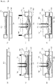
- FIG. 4 is a view sequentially showing a battery case shaping process according to the present invention.
- a battery case shaping method includes a step of disposing a laminate sheet 101 for battery cases above a die 120, a step of filling a holder 130, to which an elastic separator 140 is coupled, with a conductive liquid 150, a first shaping step of pressing the elastic separator 140 and the laminate sheet 101 using a punch 110, and a second shaping step of supplying current to the conductive liquid 150.
- the step of filling the holder 130, to which the elastic separator 140 is coupled, with the conductive liquid 150 may be performed first.
- the first shaping step and the second shaping step may be sequentially performed.
- the first shaping step is performed in an initial pressing state in which the elastic separator 140 and the laminate sheet 101 are not completely pressed.
- the first shaping step and the second shaping step may be simultaneously performed.
- the elastic separator 140 may be pressed using the punch 110, and at the same time current may be supplied to the positive electrode 161 and the negative electrode 162 in order to generate a shock wave.
- a process may be performed in which a spark is generated by the current supplied to the positive electrode 161 and the negative electrode 162, a cavity abruptly expands due to gas generated by the spark, and the conductive liquid 150 is pressurized by such expansion, whereby the elastic separator 140 pushes the laminate sheet 101 so as to come into tight contact with the surface of the die 120.
- FIG. 5 is a vertical sectional view of a battery case manufactured using the battery case shaping apparatus 100 of FIG. 1 .
- the battery case includes an electrode assembly receiving portion 201, constituted by a bottom 211 and a side surface 222, and a sealed portion 233.
- the entirety of the laminate sheet extended into the die may be uniformly elongated.
- the thicknesses of the bottom 211 and the side surface 222 constituting the electrode assembly receiving portion 201 are equal to each other, or there is no great difference therebetween.
- the sealed portion 233 which is a portion fixed to the die 120 by the holder 130, is not elongated. Consequently, the thickness of each of the bottom 211 and the side surface 222 of the elongated electrode assembly receiving portion 201 is less than the thickness of the sealed portion 233.
- the elongation region extends to an additional elongation range E2 according to the present invention in addition to the conventional elongation range E1 when the battery case shaping method according to the present invention is used, whereby it is possible to solve a conventional problem in that the battery case is locally elongated and thus is easily damaged.
- the present invention relates to a battery case shaping apparatus using a shock wave capable of reducing friction between a punch and a die and extending an elongation range of a laminate sheet in a process of shaping a pouch-shaped battery case, thereby improving shapeability of the battery case, and a battery case shaping method using the same, and therefore the present invention has industrial applicability.
Landscapes
- Engineering & Computer Science (AREA)
- Mechanical Engineering (AREA)
- Chemical & Material Sciences (AREA)
- Chemical Kinetics & Catalysis (AREA)
- Electrochemistry (AREA)
- General Chemical & Material Sciences (AREA)
- Manufacturing & Machinery (AREA)
- Physics & Mathematics (AREA)
- Fluid Mechanics (AREA)
- Sealing Battery Cases Or Jackets (AREA)
- Secondary Cells (AREA)
Abstract
Description
- This application claims the benefit of priority to
Korean Patent Application No. 2020-0141037 filed on October 28, 2020 - The present invention relates to a battery case shaping apparatus using a shock wave and a battery case shaping method using the same. More particularly, the present invention relates to a battery case shaping apparatus using a shock wave capable of reducing friction between a punch and a die and extending an elongation range of a laminate sheet in a process of shaping a pouch-shaped battery case, thereby improving shapeability of the battery case, and a battery case shaping method using the same.
- Demand for a secondary battery as an energy source for mobile devices, electric vehicles, etc. has abruptly increased. In particular, demand for a lithium secondary battery, which has high energy density and high discharge voltage, is high.
- Based on the material of a case, the lithium secondary battery may be classified as a cylindrical secondary battery made of a metal material, a prismatic secondary battery made of a metal material, or a pouch-shaped secondary battery made of a laminate sheet. The pouch-shaped secondary battery has advantages in that the pouch-shaped secondary battery is stacked with high degree of integration, thereby having high energy density per unit weight, is manufactured at low cost, and is easily deformable. Consequently, the pouch-shaped secondary battery is used in various devices.
- The pouch-shaped secondary battery uses a laminate sheet including an outer coating layer, a metal blocking layer, and an inner adhesive layer as a battery case, and is configured to have a structure in which an electrode assembly is received in a receiving portion formed in the laminate sheet together with an electrolytic solution.
- In order to shape an electrode assembly receiving portion in the pouch-shaped secondary battery, a deep drawing method of disposing a laminate sheet on a die, fixing the laminated sheet using a holder, and pressing the laminate sheet using a punch is used. During deep drawing, however, external defects, such as pinholes or cracks, are formed on the outer surface of the laminate sheet due to limited ductility of the laminate sheet and the force of friction between the punch and the laminate sheet.
- Even though surface roughness of the punch that contacts the laminate sheet is extremely reduced in order to prevent formation of such external defects, it is difficult to prevent external defects from being formed on the laminate sheet due to friction caused by repeated punching. Particularly, in the case in which the thickness of the laminate sheet, specifically the metal blocking layer, is small, shapeability of the laminate sheet is reduced, whereby pinholes or cracks may be more easily formed. For this reason, it is difficult to shape the electrode assembly receiving portion so as to have a large depth, whereby it is difficult to manufacture a high-capacity lithium secondary battery.
- In connection therewith, Patent Document 1 discloses technology capable of pressing using pressure of liquid in a punch of a press apparatus, which includes the punch, a blank holder, and a die, and generating a pressure wave in the liquid through two electrodes to form a sheet.
- However, Patent Document 1, in which an outer wall of the punch contacts the die, cannot solve a problem in that the sheet is locally elongated in a process of shaping the sheet.
- Therefore, there is a high necessity for technology capable of preventing damage to the external appearance of a laminate sheet and improving shapeability during shaping of the laminate sheet.
-
US Patent Application Publication No. 2015-0360275 (2015.12.17 ) ("Patent Document 1") - The present invention has been made in view of the above problems, and it is an object of the present invention to provide a battery case shaping apparatus capable of reducing the force of friction between a punch configured to press a laminate sheet in order to shape a battery case and the laminate sheet due to contact therebetween, thereby preventing damage to the laminate sheet, and a battery case shaping method using the same.
- In order to accomplish the above object, a battery case shaping apparatus according to the present invention includes a punch configured to press a laminate sheet for battery cases, a die located under the punch, the die forming an accommodation portion corresponding to an electrode assembly receiving portion, a holder configured to fix the laminate sheet, an elastic separator coupled to the holder, the elastic separator being located under the punch, a conductive liquid configured to form a cavity due to gas generated by electric discharge, and a positive electrode and a negative electrode each disposed in contact with the conductive liquid for the electric discharge.
- A space may be defined by the elastic separator, the holder, to which the elastic separator is coupled, and the lower surface of the punch, and the conductive liquid may be received in the space.
- A sealing member may be added to a contacting surface of the holder that contacts the punch, the contacting surface being among outer surfaces of the holder.
- A concave portion may be formed in at least a portion of the lower surface of the punch.
- The punch may include an upper punch and a lower punch, the concave portion may be formed in a central part of the lower punch, and the thickness of the lower punch excluding the central part, in which the concave portion is formed, may be gradually decreased toward the outer periphery of the lower punch, whereby the lower surface of the lower punch may be inclined.
- Specifically, the elastic separator may be a watertight elastic separator.
- The positive electrode and the negative electrode may be each fixed to the punch in a state of extending through the punch.
- The battery case shaping apparatus may further include an electricity generator coupled to the positive electrode and the negative electrode, the electricity generator being configured to supply current to the positive electrode and to the negative electrode.
- The present invention provides a battery case shaping method using the battery case shaping apparatus. Specifically, the present invention provides a battery case shaping method including S1) a step of disposing a laminate sheet for battery cases above the die, S2) a step of filling the holder, to which the elastic separator is coupled, with the conductive liquid, S3) a first shaping step of pressing the elastic separator and the laminate sheet using the punch, and S4) a second shaping step of supplying current to the conductive liquid, wherein the positive electrode and the negative electrode are each mounted to the punch.
- The first shaping step and the second shaping step may be sequentially performed.
- The punch and the elastic separator may not contact each other due to the conductive liquid, and step S2) may be performed before step S1).
- In the first shaping step, the bottom of the electrode assembly receiving portion may be shaped into a curved surface that is convex at a central part of the electrode assembly receiving portion.
- The second shaping step may include generating a spark by the current supplied to the positive electrode and to the negative electrode; expanding a cavity abruptly due to gas generated by the spark; and pressurizing the conductive liquid by the expansion, whereby the elastic separator pushes the laminate sheet so as to come into tight contact with the surface of the die.
- In addition, the present invention provides a battery case manufactured using the battery case shaping apparatus, wherein the thicknesses of a bottom and a side surface constituting the electrode assembly receiving portion may be equal to each other.
- The thickness of each of the bottom and the side surface of the electrode assembly receiving portion may be less than the thickness of a sealed portion.
- In addition, the present invention may provide all possible combinations of the above solving means.
- As is apparent from the above description, in the present invention, an electrode assembly receiving portion is shaped in the state in which an elastic separator is interposed between a laminate sheet and a punch, whereby it is possible to prevent direct contact between the punch and the laminate sheet, and therefore it is possible to minimize a stick-slip effect that occurs on the surface of the punch and the surface of the laminate sheet, and it is possible to prevent the laminate sheet from being damaged by the punch.
- In addition, a battery case is shaped in the state in which a conductive liquid is received in the elastic separator, whereby pressing force of the punch is transmitted to the elastic separator through the surface of the conductive liquid.
- In addition, since the battery case is shaped using a shock wave due to pressure of gas generated by supplying current to an electrode inserted into the conductive liquid, pressing force is distributed to the entire area of the elastic separator that abuts the laminate sheet, whereby the entirety of the laminate sheet is uniformly elongated.
- In the present invention, as described above, it is possible to reduce frictional force during a manufacturing process and to prevent the thickness of a side wall of the electrode assembly receiving portion of the battery case from being locally excessively reduced, whereby it is possible to prevent pinholes or cracks from being formed in the battery case.
- Also, in the case in which a battery case shaping apparatus and method according to the present invention are used even though laminate sheets having the same thickness are used, it is possible to more deeply form the electrode assembly receiving portion, and therefore it is possible to increase capacity of a battery cell and to improve energy density of the battery cell.
-
-
FIG. 1 is a vertical sectional view of a battery case shaping apparatus according to the present invention. -
FIG. 2 is an upper perspective view of a holder according to the present invention. -
FIG. 3 is a lower perspective view of a punch according to the present invention. -
FIG. 4 is a view sequentially showing a battery case shaping process according to the present invention. -
FIG. 5 is a vertical sectional view of a battery case manufactured using the battery case shaping apparatus ofFIG. 1 . - Now, preferred embodiments of the present invention will be described in detail with reference to the accompanying drawings such that the preferred embodiments of the present invention can be easily implemented by a person having ordinary skill in the art to which the present invention pertains. In describing the principle of operation of the preferred embodiments of the present invention in detail, however, a detailed description of known functions and configurations incorporated herein will be omitted when the same may obscure the subject matter of the present invention.
- In addition, the same reference numbers will be used throughout the drawings to refer to parts that perform similar functions or operations. In the case in which one part is said to be connected to another part throughout the specification, not only may the one part be directly connected to the other part, but also, the one part may be indirectly connected to the other part via a further part. In addition, that a certain element is included does not mean that other elements are excluded but means that such elements may be further included unless mentioned otherwise.
- In addition, a description to embody elements through limitation or addition may be applied to all inventions, unless particularly restricted, and does not limit a specific invention.
- Also, in the description of the invention and the claims of the present application, singular forms are intended to include plural forms unless mentioned otherwise.
- Also, in the description of the invention and the claims of the present application, "or" includes "and" unless mentioned otherwise. Therefore, "including A or B" means three cases, namely, the case including A, the case including B, and the case including A and B.
- In addition, all numeric ranges include the lowest value, the highest value, and all intermediate values therebetween unless the context clearly indicates otherwise.
- Embodiments of the present invention will be described in detail with reference to the accompanying drawings.
-
FIG. 1 is a vertical sectional view of a battery case shaping apparatus according to the present invention. - Referring to
FIG. 1 , the battery case shaping apparatus 100 includes apunch 110 configured to press alaminate sheet 101 for battery cases, adie 120 located under thepunch 110, the die having formed therein anaccommodation portion 121 corresponding to an electrode assembly receiving portion, aholder 130 configured to fix thelaminate sheet 101, anelastic separator 140 coupled to theholder 130, the elastic separator being located under thepunch 130, aconductive liquid 150 configured to form a cavity due to gas generated by electric discharge, and apositive electrode 161 and anegative electrode 162 disposed in contact with theconductive liquid 150 for electric discharge. - In order to manufacture a pouch-shaped battery case using the
laminate sheet 101, thelaminate sheet 101 is disposed on thedie 120 having formed therein theaccommodation portion 121 having a size corresponding to the electrode assembly receiving portion, and the outer periphery of thelaminate sheet 101 is fixed to the die using theholder 130. The fixedlaminate sheet 101 is pressed by thepunch 110, whereby the electrode assembly receiving portion may be shaped. - At this time, in order to prevent direct contact between the
laminate sheet 101 and thepunch 110, theelastic separator 140 is disposed between thelaminate sheet 101 and thepunch 110. - If the laminate sheet and the punch directly contact each other, slip does not easily occur due to friction between the surfaces of the laminate sheet and the punch. As a result, the region of the laminate sheet that is elongated is narrowed, and therefore only a local region of the laminate sheet is elongated. Specifically, since the portion of the laminate sheet that becomes a side wall of the electrode assembly receiving portion when the laminate sheet is shaped into a battery case is mainly elongated, the thickness of the portion is excessively reduced. As a result, the battery case is easily damaged.
- Since a stick-slip phenomenon easily occurs on the surface of the laminate sheet and the surface of the punch, as described above, the laminate sheet may be locally excessively elongated, and therefore a battery case shaping defect rate may be increased.
- In the present invention, the
laminate sheet 101 is pressed by thepunch 110 in the state in which theelastic separator 140 is disposed between thelaminate sheet 101 and thepunch 110, and therefore the surface of thelaminate sheet 101 and the surface of thepunch 110 do not directly contact each other. Consequently, it is possible to solve a conventional problem in that thelaminate sheet 101 is scratched due to a non-smooth surface of thepunch 110 or introduction of foreign matter between the punch and the laminate sheet. - The
elastic separator 140 may be securely fixed in theholder 130. Even though thelaminate sheet 101 is pressed by thepunch 110, therefore, stable fixing of theelastic separator 140 may be guaranteed. - For example, the
elastic separator 140 may be attached to the lower surface of theholder 130 or may be fixed to the lower part of the side surface of theholder 130. When theelastic separator 140 is attached to the lower surface of theholder 130, the force of fixing thelaminate sheet 101 may be further increased by a microscopically protruding portion formed as the result of coupling between theelastic separator 140 and theholder 130. Alternatively, when theelastic separator 140 is fixed to the lower part of the side surface of theholder 130, particularly when theelastic separator 140 is inserted into and fixed to a recess formed in the lower part of the side surface of theholder 130, the force of coupling between theelastic separator 140 and theholder 130 is further increased. As a result, coupling between the elastic separator and the holder is maintained even when theelastic separator 140 is excessively elongated. When the depth of the receiving portion is large, a more advantageous effect may be achieved. - In the present invention, the
conductive liquid 150 is added between thepunch 110 and theelastic separator 140. At this time, theconductive liquid 150 is added to such an extent that thepunch 110 and theelastic separator 140 do not contact each other. - Specifically, the
conductive liquid 150 may serve as a medium that transmits pressing force of thepunch 110, and furthermore may transmit a uniform shock wave to the entire area of theelastic separator 140. - Referring to
FIG. 1 , a space is defined by theelastic separator 140, theholder 130, to which theelastic separator 140 is coupled, and the lower surface of thepunch 110, and theconductive liquid 150 is received in the space. - Preferably, the
elastic separator 140 is a watertight elastic separator. When thepunch 110 is moved downwards, the volume of the space defined by the lower surface of thepunch 110, theholder 130, and theelastic separator 140 is reduced, whereby theconductive liquid 150 is pressurized, and the pressurizedconductive liquid 150 deforms theelastic separator 140 into a curved surface while moving downwards. - Since the pressing force applied to the deformed
elastic separator 140 is uniformly applied to the entire area of thelaminate sheet 101, thelaminate sheet 101 is also deformed into the same shape as the deformedelastic separator 140. - The pressure in the space in which the
conductive liquid 150 is received may be increased by the pressing force of thepunch 110. In order to prevent the conductive liquid 150 from being discharged from the space, a sealingmember 131 may be added tosurfaces holder 130 that contact thepunch 110, among outer surfaces of theholder 130. For example, the sealingmember 131 may be an O-ring made of an elastic material. - In connection therewith,
FIG. 2 is an upper perspective view of theholder 130 according to the present invention. - Referring to
FIGS. 1 and2 , two quadrangular ring-shapedsealing members 131 are attached to anupper surface 133 of theholder 130, and two quadrangular ring-shapedsealing members 131 are also attached to aninner surface 134 of theholder 130. - The
punch 110 ofFIG. 1 includes anupper punch 111 and alower punch 112. Theinner surface 134 of the holder is a surface that faces aside surface 112a of the lower punch inserted into theholder 120, and theupper surface 133 of the holder is a surface that faces alower surface 111a of the upper punch when thepunch 110 is completely inserted into the holder. - The sealing
member 131 is added to the surfaces of theholder 120 and thepunch 110 that face each other, whereby theelastic separator 140 may be pushed without discharge of theconductive liquid 150. - The
positive electrode 161 and thenegative electrode 162 are disposed in contact with theconductive liquid 150, and anelectricity generator 170 is coupled to thepositive electrode 161 and thenegative electrode 162 in order to supply current thereto. Thepositive electrode 161 and thenegative electrode 162 may be electrodes, polarities of which are not fixed. At this time, theelectricity generator 170 may generate alternating current. - When very high current flows to the
positive electrode 161 and thenegative electrode 162 for a very short time through theelectricity generator 170, electric discharge occurs between thepositive electrode 161 and thenegative electrode 162. The temperature of theconductive liquid 150 is abruptly increased by electric discharge, whereby the conductive liquid is evaporated, and therefore the volume of the conductive liquid is abruptly increased. As a result, a cavity is formed. When the cavity extremely expands, a shock wave is generated in the conductive liquid. In the conductive liquid, the shock wave is propagated in all directions, and energy of the shock wave strongly pushes the elastic separator and the laminate sheet to the outer edge of the accommodation portion of the die. - Since the shock wave generated as the result of evaporation of the
conductive liquid 150 expands theelastic separator 140 in all directions, as described above, thelaminate sheet 101 may be pushed to the inner surface of the die, whereby the electrode assembly receiving portion may be shaped. - It is preferable for the shock wave to be used in order to further press minute portions of the
laminate sheet 101 after the laminate sheet is shaped to some extent by pressing of thepunch 110, rather than being added from the beginning. - The kind of the
conductive liquid 150 is not particularly restricted as long as the conductive liquid exhibits high electrical conductivity, low volatility, and high chemical stability. For example, water; an electrolyte solution, such as sodium chloride, sulfuric acid, hydrochloric acid, sodium hydroxide, potassium hydroxide, or sodium nitrate; or an organic solvent used as an electrolytic solution for secondary batteries may be used. - When the punch is disposed above the laminate sheet, the
positive electrode 161 and thenegative electrode 162 are in contact with the conductive liquid. Alternatively, when the elastic separator and the laminate sheet are pushed using at least the punch, thepositive electrode 161 and thenegative electrode 162 mounted to the punch move downwards and come into contact with theconductive liquid 150. Consequently, thepositive electrode 161 and thenegative electrode 162 may be fixed to thepunch 110 in a state of extending through thepunch 110. Alternatively, thepositive electrode 161 and thenegative electrode 162 may be fixed to theholder 130 in a state of extending through theholder 130, and the positive electrode and the negative electrode may protrude from the inner surface of one side of theholder 130 toward the place at which theconductive liquid 150 is added. - Even in the case in which the positive electrode and the negative electrode are fixed to the
punch 110 or theholder 130, as described above, airtightness must be secured in order to prevent the conductive liquid 150 from being discharged from the space formed between the interior of theholder 130 and the lower surface of thepunch 110 to the outside. -
FIG. 3 is a lower perspective view of thepunch 110 according to the present invention. - Referring to
FIG. 3 , aconcave portion 115 may be formed in at least a portion of the lower surface of thelower punch 112. - It is preferable for the
concave portion 115 to be formed in a central part of the lower surface of thepunch 110 in order to prevent the conductive liquid 150 from moving to the outer periphery of theelastic separator 140 at once when thepunch 110 is moved downwards. - In the case in which the
concave portion 115 is formed in the central part of the lower surface of thepunch 110, as described above, it is possible to obtain an effect of theconductive liquid 150 being gathered in theconcave portion 115. In addition, since water pressure is better transmitted in proportion to the amount of the liquid gathered in theconcave portion 115, the central part of thepunch 110 is deformed into a convex shape, which is the most prominent, and theconcave portion 115 is added thereto. - Meanwhile, the
lower punch 112 is formed such that the thickness t1 of the central part of thelower punch 112 is greater than the thickness t2 of the outer periphery of thelower punch 112, excluding theconcave portion 115 formed in the central part of thelower punch 112. Consequently, the lower surface of thelower punch 112 is inclined. - In the present invention, the
laminate sheet 101 is pushed to the entirety of theaccommodation portion 121 of thedie 120 by a shock wave generated when theconductive liquid 150 is instantaneously evaporated, whereby the battery case is shaped. Since the thickness t2 of the outer periphery of thelower punch 112 is formed thinner than the central part of the lower punch, the shock wave may be propagated far away up to the outer periphery of theelastic separator 140. -
FIG. 4 is a view sequentially showing a battery case shaping process according to the present invention. - Referring to
FIG. 4 , a battery case shaping method according to the present invention includes a step of disposing alaminate sheet 101 for battery cases above adie 120, a step of filling aholder 130, to which anelastic separator 140 is coupled, with aconductive liquid 150, a first shaping step of pressing theelastic separator 140 and thelaminate sheet 101 using apunch 110, and a second shaping step of supplying current to theconductive liquid 150. The step of filling theholder 130, to which theelastic separator 140 is coupled, with theconductive liquid 150 may be performed first. - The first shaping step and the second shaping step may be sequentially performed. The first shaping step is performed in an initial pressing state in which the
elastic separator 140 and thelaminate sheet 101 are not completely pressed. - Alternatively, the first shaping step and the second shaping step may be simultaneously performed. The
elastic separator 140 may be pressed using thepunch 110, and at the same time current may be supplied to thepositive electrode 161 and thenegative electrode 162 in order to generate a shock wave. - In the second shaping step, in which the shock wave is used, a process may be performed in which a spark is generated by the current supplied to the
positive electrode 161 and thenegative electrode 162, a cavity abruptly expands due to gas generated by the spark, and theconductive liquid 150 is pressurized by such expansion, whereby theelastic separator 140 pushes thelaminate sheet 101 so as to come into tight contact with the surface of thedie 120. -
FIG. 5 is a vertical sectional view of a battery case manufactured using the battery case shaping apparatus 100 ofFIG. 1 . - Referring to
FIG. 5 , the battery case includes an electrodeassembly receiving portion 201, constituted by a bottom 211 and aside surface 222, and a sealedportion 233. - In the present invention, since uniform pressure is applied to the entirety of the elastic separator by the shock wave, the entirety of the laminate sheet extended into the die may be uniformly elongated.
- Consequently, the thicknesses of the bottom 211 and the
side surface 222 constituting the electrodeassembly receiving portion 201 are equal to each other, or there is no great difference therebetween. - In addition, the sealed
portion 233, which is a portion fixed to the die 120 by theholder 130, is not elongated. Consequently, the thickness of each of the bottom 211 and theside surface 222 of the elongated electrodeassembly receiving portion 201 is less than the thickness of the sealedportion 233. - When compared to the case in which a conventional elongation range E1 is applied only to the
side surface 222, therefore, the elongation region extends to an additional elongation range E2 according to the present invention in addition to the conventional elongation range E1 when the battery case shaping method according to the present invention is used, whereby it is possible to solve a conventional problem in that the battery case is locally elongated and thus is easily damaged. - Those skilled in the art to which the present invention pertains will appreciate that various applications and modifications are possible within the category of the present invention based on the above description.
-
- 100: Battery case shaping apparatus
- 101: Laminate sheet
- 10: Punch
- 111: Upper punch
- 111a: Lower surface of upper punch
- 112: Lower punch
- 112a: Side surface of lower punch
- 115: Concave portion
- 120: Die
- 121: Accommodation portion
- 130: Holder
- 131: Sealing member
- 133: Upper surface
- 134: Inner surface
- 140: Elastic separator
- 150: Conductive liquid
- 161: Positive electrode
- 162: Negative electrode
- 170: Electricity generator
- 201: Electrode assembly receiving portion
- 211: Bottom
- 222: Side surface
- 233: Sealed portion
- E1: Conventional elongation range
- E2: Additional elongation range according to present invention
- t1: Thickness of central part of lower punch
- t2: Thickness of outer periphery of lower punch
- The present invention relates to a battery case shaping apparatus using a shock wave capable of reducing friction between a punch and a die and extending an elongation range of a laminate sheet in a process of shaping a pouch-shaped battery case, thereby improving shapeability of the battery case, and a battery case shaping method using the same, and therefore the present invention has industrial applicability.
Claims (16)
- A battery case shaping apparatus comprising:a punch configured to press a laminate sheet for battery cases;a die located under the punch, the die forming an accommodation portion corresponding to an electrode assembly receiving portion;a holder configured to fix the laminate sheet;an elastic separator coupled to the holder, the elastic separator being located under the punch;a conductive liquid configured to form a cavity due to gas generated by electric discharge; anda positive electrode and a negative electrode each disposed in contact with the conductive liquid for the electric discharge.
- The battery case shaping apparatus according to claim 1, wherein:a space is defined by the elastic separator, the holder, to which the elastic separator is coupled, and a lower surface of the punch, andthe conductive liquid is received in the space.
- The battery case shaping apparatus according to claim 1, further comprising a sealing member added to a contacting surface of the holder that contacts the punch, the contacting surface being among outer surfaces of the holder.
- The battery case shaping apparatus according to claim 1, wherein a concave portion is formed in at least a portion of a lower surface of the punch.
- The battery case shaping apparatus according to claim 4, wherein:the punch comprises an upper punch and a lower punch,the concave portion is formed in a central part of the lower punch, anda thickness of the lower punch excluding the central part, in which the concave portion is formed, is gradually decreased toward an outer periphery of the lower punch, whereby a lower surface of the lower punch is inclined.
- The battery case shaping apparatus according to claim 1, wherein the elastic separator is a watertight elastic separator.
- The battery case shaping apparatus according to claim 1, wherein the positive electrode and the negative electrode are each fixed to the punch in a state of extending through the punch.
- The battery case shaping apparatus according to claim 1, further comprising an electricity generator coupled to the positive electrode and to the negative electrode, the electricity generator being configured to supply current to the positive electrode and to the negative electrode.
- A battery case shaping method using the battery case shaping apparatus according to any one of claims 1 to 8, the battery case shaping method comprising:S1) a step of disposing a laminate sheet for battery cases above the die;S2) a step of filling the holder, to which the elastic separator is coupled, with the conductive liquid;S3) a first shaping step of pressing the elastic separator and the laminate sheet using the punch; andS4) a second shaping step of supplying current to the conductive liquid,wherein the positive electrode and the negative electrode are each mounted to the punch.
- The battery case shaping method according to claim 9, wherein the first shaping step and the second shaping step are sequentially performed.
- The battery case shaping method according to claim 9, wherein the punch and the elastic separator do not contact each other due to the conductive liquid.
- The battery case shaping method according to claim 9, wherein step S2) is performed before step S1).
- The battery case shaping method according to claim 9, wherein, in the first shaping step, a bottom of the electrode assembly receiving portion is shaped into a curved surface that is convex at a central part of the electrode assembly receiving portion.
- The battery case shaping method according to claim 9, wherein the second shaping step comprises:generating a spark by the current supplied to the positive electrode and to the negative electrode;expanding a cavity abruptly due to gas generated by the spark; andpressurizing the conductive liquid by the expansion, whereby the elastic separator pushes the laminate sheet so as to come into tight contact with a surface of the die.
- A battery case manufactured using the battery case shaping apparatus according to any one of claims 1 to 8, wherein thicknesses of a bottom and a side surface constituting the electrode assembly receiving portion are equal to each other.
- The battery case according to claim 15, wherein the thickness of each of the bottom and the side surface of the electrode assembly receiving portion is less than a thickness of a sealed portion.
Applications Claiming Priority (2)
| Application Number | Priority Date | Filing Date | Title |
|---|---|---|---|
| KR1020200141037A KR20220056446A (en) | 2020-10-28 | 2020-10-28 | Molding Device of Battery Case Using Shock wave and Molding Method of Battery Case Using Thereof |
| PCT/KR2021/014296 WO2022092642A1 (en) | 2020-10-28 | 2021-10-15 | Battery case molding apparatus using shock wave, and battery case molding method using same |
Publications (3)
| Publication Number | Publication Date |
|---|---|
| EP4108429A1 true EP4108429A1 (en) | 2022-12-28 |
| EP4108429A4 EP4108429A4 (en) | 2024-02-28 |
| EP4108429B1 EP4108429B1 (en) | 2026-01-28 |
Family
ID=81382750
Family Applications (1)
| Application Number | Title | Priority Date | Filing Date |
|---|---|---|---|
| EP21886636.6A Active EP4108429B1 (en) | 2020-10-28 | 2021-10-15 | Battery case shaping apparatus using shock wave and battery case shaping method using the same |
Country Status (6)
| Country | Link |
|---|---|
| US (1) | US12614787B2 (en) |
| EP (1) | EP4108429B1 (en) |
| KR (1) | KR20220056446A (en) |
| CN (1) | CN115397655A (en) |
| ES (1) | ES3062026T3 (en) |
| WO (1) | WO2022092642A1 (en) |
Families Citing this family (3)
| Publication number | Priority date | Publication date | Assignee | Title |
|---|---|---|---|---|
| CN117225988B (en) * | 2023-11-09 | 2024-01-12 | 合肥工业大学 | Large-size thin-wall box-type part composite forming device and method |
| KR20260044682A (en) * | 2024-09-26 | 2026-04-02 | 주식회사 엘지에너지솔루션 | Pouch type exterior, forming apparatus and method of the same |
| CN119657739B (en) * | 2024-12-30 | 2026-05-05 | 华中科技大学 | Apparatus and method for electroexplosive forming or welding of tubular components based on metal foil array |
Family Cites Families (16)
| Publication number | Priority date | Publication date | Assignee | Title |
|---|---|---|---|---|
| US3248917A (en) * | 1966-05-03 | Hydrospark forming apparatus | ||
| US5540075A (en) * | 1994-10-25 | 1996-07-30 | Owens-Corning Fiberglas Technology, Inc. | Method and apparatus for shock release of thin foil materials |
| DE10110161A1 (en) | 2001-03-02 | 2003-01-02 | Audi Ag | Forming tool for hydromechanical deep drawing of workpieces from sheet metal blanks |
| JP5959205B2 (en) | 2012-01-17 | 2016-08-02 | 昭和電工パッケージング株式会社 | Battery exterior material, battery exterior material molding method and lithium secondary battery |
| FR2987288B1 (en) | 2012-02-29 | 2014-03-21 | Adm28 S Ar L | HEAD OF AN ELECTROHYDRAULIC WIRE DISCHARGE DEVICE |
| FR3000909B1 (en) | 2013-01-11 | 2015-05-15 | Adm28 S Ar L | METHOD, TOOLING AND PRESS FOR FORMING A PIECE |
| KR101467859B1 (en) * | 2013-02-18 | 2014-12-03 | 주식회사 엘지화학 | Battery Case for Secondary Battery |
| KR20140126968A (en) * | 2013-04-24 | 2014-11-03 | 삼성전자주식회사 | Impact forming apparatus and impact forming method |
| US9821359B2 (en) * | 2015-12-14 | 2017-11-21 | Rasoul Jelokhani Niaraki | High-speed hydraulic forming of metal and non-metal sheets using electromagnetic fields |
| KR102201640B1 (en) * | 2016-05-03 | 2021-01-11 | 주식회사 엘지화학 | Manufacturing Apparatus for Battery Case Capable of Deeply Forming Mounting Portion for Electrode Assembly and Method Using the Same |
| FR3058655B1 (en) | 2016-11-15 | 2019-06-07 | Adm28 S.Ar.L | ELECTROHYDRAULIC FORMING METHOD AND DEVICE THEREOF |
| KR20190098581A (en) * | 2018-02-14 | 2019-08-22 | 주식회사 엘지화학 | The Apparatus And The Method For Forming Pouch |
| AT520650B1 (en) | 2018-04-04 | 2019-06-15 | Avl Commercial Driveline & Tractor Eng Gmbh | GEAR ASSEMBLY FOR A HYBRID VEHICLE |
| CN110000283A (en) | 2018-11-09 | 2019-07-12 | 南京航空航天大学 | A kind of small round corner box part accurate forming method and its forming device |
| EP3806233B1 (en) | 2018-11-09 | 2023-11-22 | LG Energy Solution, Ltd. | Pouch forming device |
| KR102131739B1 (en) | 2018-11-09 | 2020-07-09 | 주식회사 엘지화학 | Pouch forming method and pouch forming device |
-
2020
- 2020-10-28 KR KR1020200141037A patent/KR20220056446A/en active Pending
-
2021
- 2021-10-15 EP EP21886636.6A patent/EP4108429B1/en active Active
- 2021-10-15 ES ES21886636T patent/ES3062026T3/en active Active
- 2021-10-15 US US17/925,769 patent/US12614787B2/en active Active
- 2021-10-15 WO PCT/KR2021/014296 patent/WO2022092642A1/en not_active Ceased
- 2021-10-15 CN CN202180026293.9A patent/CN115397655A/en active Pending
Also Published As
| Publication number | Publication date |
|---|---|
| US20230198055A1 (en) | 2023-06-22 |
| WO2022092642A1 (en) | 2022-05-05 |
| EP4108429B1 (en) | 2026-01-28 |
| US12614787B2 (en) | 2026-04-28 |
| KR20220056446A (en) | 2022-05-06 |
| CN115397655A (en) | 2022-11-25 |
| ES3062026T3 (en) | 2026-04-08 |
| EP4108429A4 (en) | 2024-02-28 |
Similar Documents
| Publication | Publication Date | Title |
|---|---|---|
| EP4108429B1 (en) | Battery case shaping apparatus using shock wave and battery case shaping method using the same | |
| EP3432405B1 (en) | Cylindrical battery cell manufacturing device comprising secondary crimping mold | |
| EP2733778B1 (en) | Jelly-roll with improved processability and battery cell including same | |
| CN107768559B (en) | Bipolar battery | |
| JP5269793B2 (en) | Cylindrical secondary battery with improved safety | |
| US20110123854A1 (en) | Case for secondary battery and lithium secondary battery using the same | |
| KR101623106B1 (en) | Formimg apparatus for pouch film | |
| KR102795063B1 (en) | pouch type battery case and apparatus for manufacturing thereof, pouch type secondary battery | |
| CN107112148B (en) | Electric energy storage device with improved mounting structure of internal terminals | |
| KR20140104538A (en) | Battery Case for Secondary Battery | |
| KR100586896B1 (en) | Molding apparatus for secondary battery pouch | |
| KR101104148B1 (en) | Battery Case Manufacturing Method | |
| KR102275545B1 (en) | Bettery cell and fabricating method of the same | |
| US12531427B2 (en) | Device for charging and discharging battery cell and method of charging and discharging battery cell using the same | |
| KR20170087325A (en) | Cylindrical battery can, secondary battery comprising the same and fabricating methods thereof | |
| EP3399569B1 (en) | Battery cell comprising battery case including accommodation part and electrode lead groove | |
| EP3246930A1 (en) | Electric energy storage device having improved terminal structure | |
| JP2006338992A (en) | Square lithium-ion battery | |
| US12191437B2 (en) | Apparatus for pressing battery cell | |
| CN221327908U (en) | Battery cell, end cover assembly, battery and electricity utilization device | |
| KR20190079320A (en) | Secondary battery | |
| US9065082B2 (en) | Electric storage device | |
| CN116387721B (en) | Battery and electricity utilization device | |
| EP4108416B1 (en) | Battery case forming apparatus, and battery case manufacturing method using same | |
| KR100669435B1 (en) | Secondary battery |
Legal Events
| Date | Code | Title | Description |
|---|---|---|---|
| STAA | Information on the status of an ep patent application or granted ep patent |
Free format text: STATUS: THE INTERNATIONAL PUBLICATION HAS BEEN MADE |
|
| PUAI | Public reference made under article 153(3) epc to a published international application that has entered the european phase |
Free format text: ORIGINAL CODE: 0009012 |
|
| STAA | Information on the status of an ep patent application or granted ep patent |
Free format text: STATUS: REQUEST FOR EXAMINATION WAS MADE |
|
| 17P | Request for examination filed |
Effective date: 20220923 |
|
| AK | Designated contracting states |
Kind code of ref document: A1 Designated state(s): AL AT BE BG CH CY CZ DE DK EE ES FI FR GB GR HR HU IE IS IT LI LT LU LV MC MK MT NL NO PL PT RO RS SE SI SK SM TR |
|
| DAV | Request for validation of the european patent (deleted) | ||
| DAX | Request for extension of the european patent (deleted) | ||
| A4 | Supplementary search report drawn up and despatched |
Effective date: 20240125 |
|
| RIC1 | Information provided on ipc code assigned before grant |
Ipc: B29L 31/00 20060101ALN20240119BHEP Ipc: B29C 43/32 20060101ALI20240119BHEP Ipc: H01M 50/133 20210101ALI20240119BHEP Ipc: B21D 26/12 20060101ALI20240119BHEP Ipc: H01M 50/103 20210101ALI20240119BHEP Ipc: B29C 69/02 20060101ALI20240119BHEP Ipc: B29C 43/36 20060101ALI20240119BHEP Ipc: B21D 22/30 20060101ALI20240119BHEP Ipc: B21D 26/06 20060101ALI20240119BHEP Ipc: B29C 33/20 20060101ALI20240119BHEP Ipc: B29C 51/26 20060101ALI20240119BHEP Ipc: B29C 51/08 20060101ALI20240119BHEP Ipc: H01M 50/124 20210101ALI20240119BHEP Ipc: H01M 50/116 20210101ALI20240119BHEP Ipc: B29C 67/00 20170101AFI20240119BHEP |
|
| STAA | Information on the status of an ep patent application or granted ep patent |
Free format text: STATUS: EXAMINATION IS IN PROGRESS |
|
| 17Q | First examination report despatched |
Effective date: 20250514 |
|
| RIC1 | Information provided on ipc code assigned before grant |
Ipc: B29C 67/00 20170101AFI20250926BHEP Ipc: H01M 50/116 20210101ALI20250926BHEP Ipc: H01M 50/124 20210101ALI20250926BHEP Ipc: B29C 51/08 20060101ALI20250926BHEP Ipc: B29C 51/26 20060101ALI20250926BHEP Ipc: B29C 33/20 20060101ALI20250926BHEP Ipc: B21D 26/06 20060101ALI20250926BHEP Ipc: B21D 22/30 20060101ALI20250926BHEP Ipc: B29C 43/36 20060101ALI20250926BHEP Ipc: B29C 69/02 20060101ALI20250926BHEP Ipc: H01M 50/103 20210101ALI20250926BHEP Ipc: B21D 26/12 20060101ALI20250926BHEP Ipc: H01M 50/133 20210101ALI20250926BHEP Ipc: B29C 43/32 20060101ALI20250926BHEP Ipc: B29L 31/00 20060101ALN20250926BHEP |
|
| GRAP | Despatch of communication of intention to grant a patent |
Free format text: ORIGINAL CODE: EPIDOSNIGR1 |
|
| STAA | Information on the status of an ep patent application or granted ep patent |
Free format text: STATUS: GRANT OF PATENT IS INTENDED |
|
| RIC1 | Information provided on ipc code assigned before grant |
Ipc: B29C 67/00 20170101AFI20251014BHEP Ipc: H01M 50/116 20210101ALI20251014BHEP Ipc: H01M 50/124 20210101ALI20251014BHEP Ipc: B29C 51/08 20060101ALI20251014BHEP Ipc: B29C 51/26 20060101ALI20251014BHEP Ipc: B29C 33/20 20060101ALI20251014BHEP Ipc: B21D 26/06 20060101ALI20251014BHEP Ipc: B21D 22/30 20060101ALI20251014BHEP Ipc: B29C 43/36 20060101ALI20251014BHEP Ipc: B29C 69/02 20060101ALI20251014BHEP Ipc: H01M 50/103 20210101ALI20251014BHEP Ipc: B21D 26/12 20060101ALI20251014BHEP Ipc: H01M 50/133 20210101ALI20251014BHEP Ipc: B29C 43/32 20060101ALI20251014BHEP Ipc: B29L 31/00 20060101ALN20251014BHEP |
|
| INTG | Intention to grant announced |
Effective date: 20251110 |
|
| GRAS | Grant fee paid |
Free format text: ORIGINAL CODE: EPIDOSNIGR3 |
|
| GRAA | (expected) grant |
Free format text: ORIGINAL CODE: 0009210 |
|
| STAA | Information on the status of an ep patent application or granted ep patent |
Free format text: STATUS: THE PATENT HAS BEEN GRANTED |
|
| P01 | Opt-out of the competence of the unified patent court (upc) registered |
Free format text: CASE NUMBER: UPC_APP_0015346_4108429/2025 Effective date: 20251201 |
|
| AK | Designated contracting states |
Kind code of ref document: B1 Designated state(s): AL AT BE BG CH CY CZ DE DK EE ES FI FR GB GR HR HU IE IS IT LI LT LU LV MC MK MT NL NO PL PT RO RS SE SI SK SM TR |
|
| REG | Reference to a national code |
Ref country code: CH Ref legal event code: F10 Free format text: ST27 STATUS EVENT CODE: U-0-0-F10-F00 (AS PROVIDED BY THE NATIONAL OFFICE) Effective date: 20260128 Ref country code: GB Ref legal event code: FG4D |
|
| REG | Reference to a national code |
Ref country code: DE Ref legal event code: R096 Ref document number: 602021047307 Country of ref document: DE |
|
| REG | Reference to a national code |
Ref country code: IE Ref legal event code: FG4D |
|
| REG | Reference to a national code |
Ref country code: ES Ref legal event code: FG2A Ref document number: 3062026 Country of ref document: ES Kind code of ref document: T3 Effective date: 20260408 |