EP4108384A1 - Fastening tool having a magnetic contact trip assembly - Google Patents
Fastening tool having a magnetic contact trip assembly Download PDFInfo
- Publication number
- EP4108384A1 EP4108384A1 EP22179605.5A EP22179605A EP4108384A1 EP 4108384 A1 EP4108384 A1 EP 4108384A1 EP 22179605 A EP22179605 A EP 22179605A EP 4108384 A1 EP4108384 A1 EP 4108384A1
- Authority
- EP
- European Patent Office
- Prior art keywords
- magnet
- fastening tool
- contact trip
- magnetometer
- workpiece
- Prior art date
- Legal status (The legal status is an assumption and is not a legal conclusion. Google has not performed a legal analysis and makes no representation as to the accuracy of the status listed.)
- Pending
Links
- 230000008859 change Effects 0.000 claims abstract description 21
- 230000007246 mechanism Effects 0.000 claims description 28
- 230000005355 Hall effect Effects 0.000 claims description 17
- 229920003023 plastic Polymers 0.000 claims description 11
- 239000004033 plastic Substances 0.000 claims description 11
- 229910052751 metal Inorganic materials 0.000 claims description 6
- 239000002184 metal Substances 0.000 claims description 6
- 239000000853 adhesive Substances 0.000 claims description 4
- 230000001070 adhesive effect Effects 0.000 claims description 4
- 230000004044 response Effects 0.000 claims description 4
- 230000008878 coupling Effects 0.000 claims 1
- 238000010168 coupling process Methods 0.000 claims 1
- 238000005859 coupling reaction Methods 0.000 claims 1
- 230000015654 memory Effects 0.000 description 12
- 238000004590 computer program Methods 0.000 description 6
- FXRXQYZZALWWGA-UHFFFAOYSA-N 1,2,4-trichloro-3-(4-chlorophenyl)benzene Chemical compound C1=CC(Cl)=CC=C1C1=C(Cl)C=CC(Cl)=C1Cl FXRXQYZZALWWGA-UHFFFAOYSA-N 0.000 description 4
- 230000004907 flux Effects 0.000 description 3
- 239000000463 material Substances 0.000 description 3
- -1 but not limited to Substances 0.000 description 2
- 230000006870 function Effects 0.000 description 2
- 238000002347 injection Methods 0.000 description 2
- 239000007924 injection Substances 0.000 description 2
- 238000000034 method Methods 0.000 description 2
- CWYNVVGOOAEACU-UHFFFAOYSA-N Fe2+ Chemical group [Fe+2] CWYNVVGOOAEACU-UHFFFAOYSA-N 0.000 description 1
- QJVKUMXDEUEQLH-UHFFFAOYSA-N [B].[Fe].[Nd] Chemical compound [B].[Fe].[Nd] QJVKUMXDEUEQLH-UHFFFAOYSA-N 0.000 description 1
- 229910052796 boron Inorganic materials 0.000 description 1
- 238000011109 contamination Methods 0.000 description 1
- 230000000994 depressogenic effect Effects 0.000 description 1
- 238000001514 detection method Methods 0.000 description 1
- 238000001746 injection moulding Methods 0.000 description 1
- 230000004048 modification Effects 0.000 description 1
- 238000012986 modification Methods 0.000 description 1
- 229910001172 neodymium magnet Inorganic materials 0.000 description 1
- 230000003287 optical effect Effects 0.000 description 1
- 238000004382 potting Methods 0.000 description 1
- 230000001902 propagating effect Effects 0.000 description 1
- ZLIBICFPKPWGIZ-UHFFFAOYSA-N pyrimethanil Chemical compound CC1=CC(C)=NC(NC=2C=CC=CC=2)=N1 ZLIBICFPKPWGIZ-UHFFFAOYSA-N 0.000 description 1
- 239000010979 ruby Substances 0.000 description 1
- 239000004065 semiconductor Substances 0.000 description 1
- 230000035939 shock Effects 0.000 description 1
- 230000003068 static effect Effects 0.000 description 1
- 230000000007 visual effect Effects 0.000 description 1
Images




Classifications
-
- B—PERFORMING OPERATIONS; TRANSPORTING
- B25—HAND TOOLS; PORTABLE POWER-DRIVEN TOOLS; MANIPULATORS
- B25C—HAND-HELD NAILING OR STAPLING TOOLS; MANUALLY OPERATED PORTABLE STAPLING TOOLS
- B25C1/00—Hand-held nailing tools; Nail feeding devices
- B25C1/008—Safety devices
-
- B—PERFORMING OPERATIONS; TRANSPORTING
- B25—HAND TOOLS; PORTABLE POWER-DRIVEN TOOLS; MANIPULATORS
- B25C—HAND-HELD NAILING OR STAPLING TOOLS; MANUALLY OPERATED PORTABLE STAPLING TOOLS
- B25C5/00—Manually operated portable stapling tools; Hand-held power-operated stapling tools; Staple feeding devices therefor
Definitions
- the present disclosure relates in general to fastening tools for driving fasteners such as nails or staples into a workpiece and, more particularly, to fastening tools having a magnetic contact trip assembly.
- a fastening tool for driving fasteners such as nails or staples into a workpiece typically includes a mechanical contact trip switch that detects when the nosepiece of the fastening tool is pressed against a workpiece.
- An example of such a mechanical contact trip switch is labelled 10 in FIG. 1 .
- the mechanical contact trip switch 10 includes a metal upper contact trip 12, a contact sensor 14, an override mechanism or mechanical decoupler 16, and a plastic depth adjustment wheel 18.
- the upper contact trip 12 moves in a rearward direction 20 relative to the nosepiece (not shown) of the fastening tool when a front end 22 of the upper contact trip 12 engages a lower contact trip (not shown), which in turn engages the workpiece.
- the contact sensor 14 detects movement of the upper contact trip 12 due to engagement with the workpiece when the upper contact trip 12 contacts the contact sensor 14.
- the mechanical decoupler 16 decouples the movement and force of the upper contact trip 12 from the contact sensor 14 to prevent damage to the contact sensor 14.
- the mechanical decoupler 16 includes a plastic housing 24 and a coil spring 26 that is captured between the upper contact trip 12 and the plastic housing 24.
- the mechanical decoupler 16 includes a mechanical override or ramp.
- the depth adjustment wheel 18 is rotatable to set the distance by which the upper contact trip 12 protrudes from the nosepiece and thereby set the depth to which the fastening tool drive the fastener into the workpiece.
- a mechanical contact trip switch in a fastening tool such a nail or staple gun is subject to shock, vibration, and impact and has a high life cycle requirement.
- Mechanical type switches have reliability limits due to mechanical wear, internal contamination, friction, and fatigue.
- the fastening tool includes a contact trip, a magnet, and a magnetometer.
- the contact trip is disposed at a first end of the fastening tool and is configured to move toward a second end of the fastening tool opposite of the first end when the contact trip engages the workpiece.
- the magnet is configured to generate a magnetic field.
- the magnet is coupled to the contact trip such that movement of the contact trip causes the magnet to move.
- the magnetometer is configured to detect a change in the magnetic field generated by the magnet when the magnet moves relative to the magnetometer and, based on the detected change in the magnetic field, to generate a signal indicating when the contact trip engages the workpiece.
- the magnetometer is a Hall effect sensor.
- the fastening tool further includes a depth adjustment mechanism connected to the contact trip such that movement of the contact trip causes the depth adjustment mechanism to move.
- the depth adjustment mechanism couples the magnet to the contact trip.
- the depth adjustment mechanism includes a first spindle and a second spindle threadedly connected to the first spindle and coaxial with the first spindle.
- the first and second spindles are configured to translate along a longitudinal axis thereof.
- the fastening tool further includes a linkage that couples the magnet to the depth adjustment mechanism and positions the magnet adjacent to the magnetometer.
- the magnet is directly coupled to the contact trip.
- the fastening tool further includes a linkage that couples the magnet to the contact trip and positions the magnet adjacent to the magnetometer.
- the linkage is indirectly coupled to the contact trip.
- the linkage is made of plastic and is molded over the magnet.
- the magnet is secured within a bore in the linkage using at least one of a snap fit, a press fit, and an adhesive.
- the linkage is a unitary body made of metal.
- the magnet is disposed within a bore in the linkage and is captured within the bore using a cover that is secured to the linkage using a snap fit.
- the magnet has a north pole and a south pole disposed at opposite ends of the magnet along a longitudinal axis thereof, and the longitudinal axis of the magnet is parallel to a direction in which the magnet travels when the contact trip engages the workpiece.
- the fastening tool further includes an actuator and a control module.
- the control module is configured to receive the signal generated by the magnetometer and, in response to the signal, to control the actuator to drive the fastener into the workpiece.
- control module is configured to control the actuator to drive the fastener into the workpiece based on the change in a polarity of the magnetic field generated by the magnet.
- control module is configured to control the actuator to drive the fastener into the workpiece based on the change in a magnitude of the magnetic field generated by the magnet.
- the fastening tool is a nailer.
- the magnet is a permanent magnet.
- the magnetic contact trip assembly 30 does not need to include a mechanical decoupler such as the mechanical decoupler 16 of FIG. 1 .
- the material and assembly cost of the magnetic contact trip assembly 30 may be less than that of a mechanical contact trip switch such as the mechanical contact trip switch of FIG. 1 .
- the magnetic contact trip assembly 30 may have improved reliability relative to a mechanical contact trip switch.
- the nosepiece 60 is attached to the housing 56 and forms the front end 52 of the fastening tool 50.
- the fastener magazine 62 is attached to the housing 56 and/or the nosepiece 60 and is configured to hold a plurality of fasteners (e.g., nails).
- the PCB 64 is attached to the fastener magazine 62.
- the PCB 64 may be attached to the nosepiece 60 and/or a mount for a depth adjustment mechanism 74.
- the control module 66 is disposed on the PCB 64 and is configured to control the actuator 68 to drive a fastener from the fastener magazine 62 into a workpiece.
- the actuator 68 is attached to the housing 56 and may include an electric motor, a flywheel, a power take off, and a nail driving mechanism.
- the fork 84 of the contact trip 72 receives a cylindrical body 97 of the second spindle 92 and is captured between disks 98 that protrude radially outward from the cylindrical body 97.
- the second spindle 92 can be unthreaded out of the first spindle 90 to increase the distance by which the contact trip 72 protrudes from the fastening tool 50 and thereby decrease the depth at which the fastening tool 50 drives the fastener into the workpiece.
- the second spindle 92 can be threaded into the first spindle 90 to decrease the distance by which the contact trip 72 protrudes from the fastening tool 50 and thereby increase the depth at which the fastening tool 50 drives the fastener into the workpiece.
- the cover 108 may be secured to the linkage 76 to close the bore 106 on one side of the magnet 78, and a similar or identical cover may be secured to the linkage 76 to close the bore 106 on the other side of the magnet 78.
- the bore 106 may be a blind bore and the cover 108 may be secured to the linkage 76 to close the bore 106 after the magnet 78 is inserted into the bore 106.
- the magnet 78 generates a magnetic field and may be a permanent magnet.
- the magnet 78 is coupled to the contact trip 72 such that movement of the contact trip 72 causes the magnet 78 to move.
- the magnet 78 may move the same distance as the contact trip 72.
- the magnet 78 is coupled to the contact trip 72 via the linkage 76 and the depth adjustment mechanism 74.
- the magnet 78 has a north pole 110 and a south pole 112 disposed at opposite ends of the magnet 78 along a longitudinal axis 114 thereof.
- the longitudinal axis 114 of the magnet 78 is parallel to the rearward direction 86 in which the magnet 78 travels when the contact trip 72 engages the workpiece.
- the magnetometer 80 detects a change in the magnetic field generated by the magnet 78 when the magnet 78 moves relative to the magnetometer 80. Based on the detected change in the magnetic field, the magnetometer 80 generates a signal indicating when the contact trip 72 engages the workpiece.
- the magnetometer 80 may be a Hall effect sensor.
- the magnetometer 80 is coupled to the fastener magazine 62 via the PCB 64. In other examples, the magnetometer 80 may be directly or indirectly coupled to the nosepiece 60.
- the control module 66 receives the signal generated by the magnetometer 36 and, in response to the signal, controls the actuator 68 to drive the fastener into the workpiece 44.
- the control module 66 may control the actuator 68 to drive the fastener into the workpiece when the polarity of the magnetic field generated by the magnet 78 and detected by the magnetometer 80 changes from positive to negative or vice versa. Additionally or alternatively, the control module 66 may control the actuator 68 to drive the fastener into the workpiece when a change in the magnitude of the magnetic field generated by the magnet 78 and detected by the magnetometer 80 is greater than a threshold.
- the contact trip 72, the depth adjustment mechanism 74, and the linkage 76 are allowed to return to their original positions (i.e., their positions before the contact trip 72 engaged the workpiece).
- the contact trip 72, the depth adjustment mechanism 74, and the linkage 76 are biased toward the front end 52 of the fastening tool 50 by a spring 116 that is captured between the nosepiece 60 and the linkage 76.
- the spring returns the contact trip 72, the depth adjustment mechanism 74, and the linkage 76 to their original positions.
- control module 66 may control the actuator 68 to drive the fastener into the workpiece when a change in the magnitude of the magnetic field generated by the magnet 78 and detected by the magnetometer 80 is greater than a threshold. Additionally or alternatively, the control module 66 may control the actuator 68 to drive the fastener into the workpiece when the magnetometer 80 does or does not detect the magnetic field generated by the magnet 78.
- the magnet holding portion 104 of the linkage 76 may be annular as shown in FIG. 6 instead of U-shaped as shown in FIG. 4 .
- the magnetometer 80 may include one or more Hall effect sensors or other types of magnetometers.
- the magnetometer 80 may be replaced with a magnetoresistor or magnetoresistive sensor.
- the magnetometer 80 may be replaced with another type of sensor that can detect a change in the magnetic field or flux and has an output that can serve as a basis for controlling the actuator 68.
- the magnetometer 80 may be replaced with another type of sensor that detects a change in characteristic of a sensor target.
- Hall effect sensors that can be used include a bipolar Hall effect sensor, a linear Hall effect sensor, a discrete Hall effect sensor, and a magnetoresistive Hall effect sensor. Hall effect sensors that do or do not have built-in amplifiers can be used.
- the Hall effect sensor can be oriented relative to the magnet 78 such that when the magnetic field of the magnet 78 is disrupted by a ferrous part, the flux detected by the Hall effect sensor changes polarity. This change in the polarity of the flux causes the sensor to change the signal it sends to the control module 66, indicating that the fastening tool 50 is pressed against the workpiece.
- Magnets and Hall effect sensors could be incorporated into the fastening tool 50 at a variety of locations that allow movement of the magnets relative to the sensors. This disclosure is not limited in regard to a means to place or fix the magnets for detection by the Hall effect sensors. A magnet can be affixed to a component of the fastening tool 50 and/or to tool potting.
- the magnets can be configured at various distances and in a number of configurations in relation to the Hall effect sensors.
- One magnet or a number of magnets can be used to provide input to the Hall effect sensor. Magnets of different strengths and different polarities can be used.
- the magnet 78 may include N35 magnets and/or N35SH magnets.
- the magnet 78 may include other types of magnets such as Neodymium Iron Boron magnets.
- the magnet 78 may include magnetic sources that are not permanent magnets such as magnetized plastics, or magnetically infused plastics (e.g. slider having magnetized portions, magnetized elements, magnetized components, or magnetized plastic portions).
- Spatial and functional relationships between elements are described using various terms, including “connected,” “engaged,” “coupled,” “adjacent,” “next to,” “on top of,” “above,” “below,” and “disposed.” Unless explicitly described as being “direct,” when a relationship between first and second elements is described in the above disclosure, that relationship can be a direct relationship where no other intervening elements are present between the first and second elements, but can also be an indirect relationship where one or more intervening elements are present (either spatially or functionally) between the first and second elements.
- spatially relative terms such as “inner,” “outer,” “beneath,” “below,” “lower,” “above,” “upper,” and the like, may be used herein for ease of description to describe one element or feature's relationship to another element(s) or feature(s) as illustrated in the figures.
- Spatially relative terms may be intended to encompass different orientations of the device in use or operation in addition to the orientation depicted in the figures. For example, if the device in the figures is turned over, elements described as “below” or “beneath” other elements or features would then be oriented “above” the other elements or features.
- the example term “below” can encompass both an orientation of above and below.
- the device may be otherwise oriented (rotated 90 degrees or at other orientations) and the spatially relative descriptors used herein interpreted accordingly.
- first, second, third, etc. may be used herein to describe various elements, components, regions, layers and/or sections, these elements, components, regions, layers and/or sections should not be limited by these terms. These terms may be only used to distinguish one element, component, region, layer or section from another region, layer or section. Terms such as “first,” “second,” and other numerical terms when used herein do not imply a sequence or order unless clearly indicated by the context. Thus, a first element, component, region, layer or section discussed below could be termed a second element, component, region, layer or section without departing from the teachings of the example embodiments.
- the term "and/or" includes any and all combinations of one or more of the associated listed items.
- the phrase at least one of A, B, and C should be construed to mean a logical (A OR B OR C), using a non-exclusive logical OR, and should not be construed to mean "at least one of A, at least one of B, and at least one of C.”
- the direction of an arrow generally demonstrates the flow of information (such as data or instructions) that is of interest to the illustration.
- information such as data or instructions
- the arrow may point from element A to element B. This unidirectional arrow does not imply that no other information is transmitted from element B to element A.
- element B may send requests for, or receipt acknowledgements of, the information to element A.
- the module may include one or more interface circuits.
- the interface circuits may include wired or wireless interfaces that are connected to a local area network (LAN), the Internet, a wide area network (WAN), or combinations thereof.
- LAN local area network
- WAN wide area network
- the functionality of any given module of the present disclosure may be distributed among multiple modules that are connected via interface circuits. For example, multiple modules may allow load balancing.
- a server (also known as remote, or cloud) module may accomplish some functionality on behalf of a client module.
- code may include software, firmware, and/or microcode, and may refer to programs, routines, functions, classes, data structures, and/or objects.
- shared processor circuit encompasses a single processor circuit that executes some or all code from multiple modules.
- group processor circuit encompasses a processor circuit that, in combination with additional processor circuits, executes some or all code from one or more modules. References to multiple processor circuits encompass multiple processor circuits on discrete dies, multiple processor circuits on a single die, multiple cores of a single processor circuit, multiple threads of a single processor circuit, or a combination of the above.
- shared memory circuit encompasses a single memory circuit that stores some or all code from multiple modules.
- group memory circuit encompasses a memory circuit that, in combination with additional memories, stores some or all code from one or more modules.
- the term memory circuit is a subset of the term computer-readable medium.
- the term computer-readable medium does not encompass transitory electrical or electromagnetic signals propagating through a medium (such as on a carrier wave); the term computer-readable medium may therefore be considered tangible and non-transitory.
- Non-limiting examples of a non-transitory, tangible computer-readable medium are nonvolatile memory circuits (such as a flash memory circuit, an erasable programmable read-only memory circuit, or a mask read-only memory circuit), volatile memory circuits (such as a static random access memory circuit or a dynamic random access memory circuit), magnetic storage media (such as an analog or digital magnetic tape or a hard disk drive), and optical storage media (such as a CD, a DVD, or a Blu-ray Disc).
- nonvolatile memory circuits such as a flash memory circuit, an erasable programmable read-only memory circuit, or a mask read-only memory circuit
- volatile memory circuits such as a static random access memory circuit or a dynamic random access memory circuit
- magnetic storage media such as an analog or digital magnetic tape or a hard disk drive
- optical storage media such as a CD, a DVD, or a Blu-ray Disc
- the apparatuses and methods described in this application may be partially or fully implemented by a special purpose computer created by configuring a general purpose computer to execute one or more particular functions embodied in computer programs.
- the functional blocks, flowchart components, and other elements described above serve as software specifications, which can be translated into the computer programs by the routine work of a skilled technician or programmer.
- the computer programs include processor-executable instructions that are stored on at least one non-transitory, tangible computer-readable medium.
- the computer programs may also include or rely on stored data.
- the computer programs may encompass a basic input/output system (BIOS) that interacts with hardware of the special purpose computer, device drivers that interact with particular devices of the special purpose computer, one or more operating systems, user applications, background services, background applications, etc.
- BIOS basic input/output system
- the computer programs may include: (i) descriptive text to be parsed, such as HTML (hypertext markup language), XML (extensible markup language), or JSON (JavaScript Object Notation) (ii) assembly code, (iii) object code generated from source code by a compiler, (iv) source code for execution by an interpreter, (v) source code for compilation and execution by a just-in-time compiler, etc.
- source code may be written using syntax from languages including C, C++, C#, Objective-C, Swift, Haskell, Go, SQL, R, Lisp, Java ® , Fortran, Perl, Pascal, Curl, OCaml, Javascript ® , HTML5 (Hypertext Markup Language 5th revision), Ada, ASP (Active Server Pages), PHP (PHP: Hypertext Preprocessor), Scala, Eiffel, Smalltalk, Erlang, Ruby, Flash ® , Visual Basic ® , Lua, MATLAB, SIMULINK, and Python ® .
- languages including C, C++, C#, Objective-C, Swift, Haskell, Go, SQL, R, Lisp, Java ® , Fortran, Perl, Pascal, Curl, OCaml, Javascript ® , HTML5 (Hypertext Markup Language 5th revision), Ada, ASP (Active Server Pages), PHP (PHP: Hypertext Preprocessor), Scala, Eiffel, Smalltalk, Erlang, Ruby, Flash
Landscapes
- Engineering & Computer Science (AREA)
- Mechanical Engineering (AREA)
- Portable Nailing Machines And Staplers (AREA)
- Details Of Spanners, Wrenches, And Screw Drivers And Accessories (AREA)
Abstract
Description
- The present disclosure relates in general to fastening tools for driving fasteners such as nails or staples into a workpiece and, more particularly, to fastening tools having a magnetic contact trip assembly.
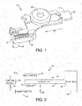
- A fastening tool for driving fasteners such as nails or staples into a workpiece typically includes a mechanical contact trip switch that detects when the nosepiece of the fastening tool is pressed against a workpiece. An example of such a mechanical contact trip switch is labelled 10 in
FIG. 1 . The mechanicalcontact trip switch 10 includes a metalupper contact trip 12, acontact sensor 14, an override mechanism ormechanical decoupler 16, and a plasticdepth adjustment wheel 18. Theupper contact trip 12 moves in arearward direction 20 relative to the nosepiece (not shown) of the fastening tool when afront end 22 of theupper contact trip 12 engages a lower contact trip (not shown), which in turn engages the workpiece. Thecontact sensor 14 detects movement of theupper contact trip 12 due to engagement with the workpiece when theupper contact trip 12 contacts thecontact sensor 14. - The
mechanical decoupler 16 decouples the movement and force of theupper contact trip 12 from thecontact sensor 14 to prevent damage to thecontact sensor 14. In the example shown, themechanical decoupler 16 includes aplastic housing 24 and acoil spring 26 that is captured between theupper contact trip 12 and theplastic housing 24. In other examples, themechanical decoupler 16 includes a mechanical override or ramp. Thedepth adjustment wheel 18 is rotatable to set the distance by which theupper contact trip 12 protrudes from the nosepiece and thereby set the depth to which the fastening tool drive the fastener into the workpiece. - A mechanical contact trip switch in a fastening tool such a nail or staple gun is subject to shock, vibration, and impact and has a high life cycle requirement. Mechanical type switches have reliability limits due to mechanical wear, internal contamination, friction, and fatigue.
- A fastening tool for driving a fastener into a workpiece is described herein. In one example, the fastening tool includes a contact trip, a magnet, and a magnetometer. The contact trip is disposed at a first end of the fastening tool and is configured to move toward a second end of the fastening tool opposite of the first end when the contact trip engages the workpiece. The magnet is configured to generate a magnetic field. The magnet is coupled to the contact trip such that movement of the contact trip causes the magnet to move. The magnetometer is configured to detect a change in the magnetic field generated by the magnet when the magnet moves relative to the magnetometer and, based on the detected change in the magnetic field, to generate a signal indicating when the contact trip engages the workpiece.
- In one aspect, the magnetometer is a Hall effect sensor.
- In one aspect, the fastening tool further includes a depth adjustment mechanism connected to the contact trip such that movement of the contact trip causes the depth adjustment mechanism to move. The depth adjustment mechanism couples the magnet to the contact trip.
- In one aspect, the depth adjustment mechanism includes a first spindle and a second spindle threadedly connected to the first spindle and coaxial with the first spindle. The first and second spindles are configured to translate along a longitudinal axis thereof.
- In one aspect, the fastening tool further includes a linkage that couples the magnet to the depth adjustment mechanism and positions the magnet adjacent to the magnetometer.
- In one aspect, the magnet is directly coupled to the contact trip.
- In one aspect, the fastening tool further includes a linkage that couples the magnet to the contact trip and positions the magnet adjacent to the magnetometer.
- In one aspect, the linkage is indirectly coupled to the contact trip.
- In one aspect, the linkage is made of plastic and is molded over the magnet.
- In one aspect, the magnet is secured within a bore in the linkage using at least one of a snap fit, a press fit, and an adhesive.
- In one aspect, the linkage is a unitary body made of metal.
- In one aspect, the magnet is disposed within a bore in the linkage and is captured within the bore using a cover that is secured to the linkage using a snap fit.
- In one aspect, the magnet has a north pole and a south pole disposed at opposite ends of the magnet along a longitudinal axis thereof, and the longitudinal axis of the magnet is parallel to a direction in which the magnet travels when the contact trip engages the workpiece.
- In one aspect, the magnet has a north pole and a south pole disposed at opposite ends of the magnet along a longitudinal axis thereof, and the longitudinal axis of the magnet is perpendicular to a direction in which the magnet travels when the contact trip engages the workpiece.
- In one aspect, the fastening tool further includes an actuator and a control module. The control module is configured to receive the signal generated by the magnetometer and, in response to the signal, to control the actuator to drive the fastener into the workpiece.
- In one aspect, the control module is configured to control the actuator to drive the fastener into the workpiece based on the change in a polarity of the magnetic field generated by the magnet.
- In one aspect, the control module is configured to control the actuator to drive the fastener into the workpiece based on the change in a magnitude of the magnetic field generated by the magnet.
- In one aspect, the fastening tool is a nailer.
- In one aspect, the magnet is a permanent magnet.
- In one aspect, when the contact trip engages the workpiece, the magnet moves from one side of the magnetometer to another side of the magnetometer in a direction extending between the first and second ends of the fastening tool.
- Further areas of applicability of the present disclosure will become apparent from the detailed description, the claims and the drawings. The detailed description and specific examples are intended for purposes of illustration only and are not intended to limit the scope of the disclosure.
- The present disclosure will become more fully understood from the detailed description and the accompanying drawings, wherein:
-
FIG. 1 is a perspective view of an example of a mechanical contact trip switch according to the prior art; -
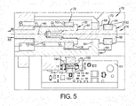
FIG. 2 is a schematic of an example of a magnetic contact trip assembly according to the present disclosure; -
FIG. 3 is a perspective view of an example of a fastening tool including another example of a magnetic contact trip assembly according to the present disclosure; -
FIG. 4 is an enlarged perspective view of the magnetic contact trip assembly ofFIG. 3 ; -
FIG. 5 is a section view of the magnetic contact trip assembly ofFIG. 3 ; -
FIG. 6 is a perspective view of another example of a magnetic contact trip assembly according to the present disclosure; and -
FIG. 7 is a section view of the magnetic contact trip assembly ofFIG. 6 . - In the drawings, reference numbers may be reused to identify similar and/or identical elements.
- A fastening tool according to the present disclosure includes a magnetic contact trip assembly that detects when the nosepiece of the fastening tool is pressed against a workpiece. An example of such a magnetic contact trip assembly is schematically illustrated and labelled 30 in
FIG. 2 . The magneticcontact trip assembly 30 includes acontact trip 32, a magnet 34 (e.g., a permanent magnet) directly or indirectly coupled to thecontact trip 32, and a magnetometer 36 (e.g., a Hall effect sensor) that is spaced apart from themagnet 34 by agap 38. In the example shown, themagnet 34 is directly coupled to thecontact trip 32. In other example, themagnet 34 may be indirectly coupled to the contact trip via a depth adjustment mechanism. Thecontact trip 32 moves in arearward direction 40 relative to the nosepiece (not shown) of the fastening tool when afront end 42 of thecontact trip 32 engages aworkpiece 44. - The
magnet 34 generates a magnetic field. Themagnetometer 36 detects a change in the magnetic field generated by themagnet 34 when themagnet 34 moves relative to themagnetometer 36. Based on the detected change in the magnetic field, themagnetometer 36 generates an analog ordigital signal 45 indicating when thecontact trip 32 engages theworkpiece 44. Acontrol module 46 receives thesignal 45 generated by themagnetometer 36 and, in response to thesignal 45, generates asignal 47 to control an actuator 48 (e.g., an electric motor) to drive the fastener into theworkpiece 44. - Since the
contact trip 32 does not contact themagnetometer 36 as thecontact trip 32 moves in therearward direction 40, the magneticcontact trip assembly 30 does not need to include a mechanical decoupler such as themechanical decoupler 16 ofFIG. 1 . Thus, the material and assembly cost of the magneticcontact trip assembly 30 may be less than that of a mechanical contact trip switch such as the mechanical contact trip switch ofFIG. 1 . In addition, due to the lack of contact between thecontact trip 32 and themagnetometer 36, the magneticcontact trip assembly 30 may have improved reliability relative to a mechanical contact trip switch. -
FIGS. 3 through 5 illustrate an example of afastening tool 50 according to the present disclosure. Thefastening tool 50 is operable to drive fasteners such as nails or staples into a workpiece. In the example shown, thefastening tool 50 is a nailer. Thefastening tool 50 has afront end 52 and arear end 54 opposite of thefront end 52. Thefastening tool 50 includes ahousing 56, atrigger 58, anosepiece 60, afastener magazine 62, a printed circuit board (PCB) 64, acontrol module 66, anactuator 68, and a magneticcontact trip assembly 70. - The
nosepiece 60 is attached to thehousing 56 and forms thefront end 52 of thefastening tool 50. Thefastener magazine 62 is attached to thehousing 56 and/or thenosepiece 60 and is configured to hold a plurality of fasteners (e.g., nails). In the example shown, thePCB 64 is attached to thefastener magazine 62. In other examples, thePCB 64 may be attached to thenosepiece 60 and/or a mount for adepth adjustment mechanism 74. Thecontrol module 66 is disposed on thePCB 64 and is configured to control theactuator 68 to drive a fastener from thefastener magazine 62 into a workpiece. Theactuator 68 is attached to thehousing 56 and may include an electric motor, a flywheel, a power take off, and a nail driving mechanism. - As best shown in
FIGS. 4 and5 , the magneticcontact trip assembly 70 includes acontact trip 72, thedepth adjustment mechanism 74, alinkage 76, amagnet 78, and amagnetometer 80. Thecontact trip 72 is made of materials including, but not limited to, plastic and metal. Thecontact trip 72 includes amain body 82 and afork 84 protruding from themain body 82. When themain body 82 of thecontact trip 72 engages a workpiece, thefork 84 of thecontact trip 72 moves in arearward direction 86 toward therear end 54 of thefastening tool 50. Thecontact trip 72 is coupled to thenosepiece 60 in a manner that allows thecontact trip 72 to move relative to thenosepiece 60. For example, thecontact trip 72 may be coupled to thenosepiece 60 using a bracket and rail coupler (not shown) that allows thecontact trip 72 to translate in therearward direction 86 and in aforward direction 88 opposite of therearward direction 86. - The
depth adjustment mechanism 74 is coupled to thenosepiece 60 in a manner that allows thedepth adjustment mechanism 74 to translate relative to thenosepiece 60. In addition, thedepth adjustment mechanism 74 is connected to thecontact trip 72 such that movement of thecontact trip 72 causes thedepth adjustment mechanism 74 to move. Thedepth adjustment mechanism 74 can be made of a material including, but not limited to, metal. Thedepth adjustment mechanism 74 includes afirst spindle 90 and asecond spindle 92 threadedly connected to thefirst spindle 90 and coaxial with thefirst spindle 90. Thenosepiece 60 forms abearing 94 that supports thesecond spindle 92 while allowing thesecond spindle 92 to translate relative to thenosepiece 60. The first andsecond spindles longitudinal axis 96 thereof in the rearward andforward directions - The
fork 84 of thecontact trip 72 receives acylindrical body 97 of thesecond spindle 92 and is captured betweendisks 98 that protrude radially outward from thecylindrical body 97. Thesecond spindle 92 can be unthreaded out of thefirst spindle 90 to increase the distance by which thecontact trip 72 protrudes from thefastening tool 50 and thereby decrease the depth at which thefastening tool 50 drives the fastener into the workpiece. Conversely, thesecond spindle 92 can be threaded into thefirst spindle 90 to decrease the distance by which thecontact trip 72 protrudes from thefastening tool 50 and thereby increase the depth at which thefastening tool 50 drives the fastener into the workpiece. - The
linkage 76 couples themagnet 78 to thedepth adjustment mechanism 74 and positions themagnet 78 adjacent to themagnetometer 80 while providing a gap 99 (FIG. 7 ) therebetween. In the example shown, thelinkage 76 is indirectly coupled to thecontact trip 72 via thedepth adjustment mechanism 74. In other examples, thelinkage 76 may be directly coupled to thecontact trip 72. Also, in the example shown, thelinkage 76 is spaced apart from the part holding the magnetometer 80 (e.g., thenosepiece 60 or the fastener magazine 62). In other examples, the part holding themagnetometer 80 may define a slot through which thelinkage 76 is guided. Thelinkage 76 may be a unitary body or multiple pieces connected to one another. Thelinkage 76 may be injection molded from plastic or stamped from (sheet) metal. In various implementations, thelinkage 76 and/or themagnet 78 may be arranged coaxial with the first andsecond spindles magnet 78 may have a hole or orifice through which thefirst spindle 90 and/or thesecond spindle 92 pass(es) through. - The
linkage 76 includes a connectingportion 100, anannular portion 102 attached to one end of the connectingportion 100, and amagnet holding portion 104 attached to the other end of the connectingportion 100. As shown inFIG. 4 , the connectingportion 100 of thelinkage 76 may be rectangular and themagnet holding portion 104 of thelinkage 76 may be U-shaped. Theannular portion 102 of thelinkage 76 extends around thefirst spindle 90 of thedepth adjustment mechanism 74 and may be secured thereto using a press fit and/or adhesive, and/or by injection molding thelinkage 76 over thefirst spindle 90. Themagnet holding portion 104 of thelinkage 76 defines abore 106 in which themagnet 78 is disposed. - The
linkage 76 may be made of plastic and (injection) molded over themagnet 78 to form thebore 106 and to secure themagnet 78 within thebore 106. Alternatively, themagnet 78 may be secured within thebore 106 in thelinkage 76 using one or more of a snap fit, a press fit, and an adhesive. Additionally or alternatively, themagnet 78 may be captured within thebore 106 using a cover 108 (shown exploded inFIG. 5 ) that is secured to thelinkage 76 using a snap fit. The cover 108 may be disk shaped and may fit within thebore 106. The cover 108 may be secured to thelinkage 76 to close thebore 106 on one side of themagnet 78, and a similar or identical cover may be secured to thelinkage 76 to close thebore 106 on the other side of themagnet 78. Alternatively, thebore 106 may be a blind bore and the cover 108 may be secured to thelinkage 76 to close thebore 106 after themagnet 78 is inserted into thebore 106. - The
magnet 78 generates a magnetic field and may be a permanent magnet. Themagnet 78 is coupled to thecontact trip 72 such that movement of thecontact trip 72 causes themagnet 78 to move. Themagnet 78 may move the same distance as thecontact trip 72. In the example shown, themagnet 78 is coupled to thecontact trip 72 via thelinkage 76 and thedepth adjustment mechanism 74. As shown inFIG. 5 , themagnet 78 has anorth pole 110 and asouth pole 112 disposed at opposite ends of themagnet 78 along a longitudinal axis 114 thereof. The longitudinal axis 114 of themagnet 78 is parallel to therearward direction 86 in which themagnet 78 travels when thecontact trip 72 engages the workpiece. - The
magnetometer 80 detects a change in the magnetic field generated by themagnet 78 when themagnet 78 moves relative to themagnetometer 80. Based on the detected change in the magnetic field, themagnetometer 80 generates a signal indicating when thecontact trip 72 engages the workpiece. Themagnetometer 80 may be a Hall effect sensor. In the example shown, themagnetometer 80 is coupled to thefastener magazine 62 via thePCB 64. In other examples, themagnetometer 80 may be directly or indirectly coupled to thenosepiece 60. Thecontrol module 66 receives the signal generated by themagnetometer 36 and, in response to the signal, controls theactuator 68 to drive the fastener into theworkpiece 44. In various implementations, thecontrol module 66 may refrain from controlling theactuator 68 to drive the fastener into theworkpiece 44 unless thecontrol module 66 receives both the signal indicating that thecontact trip 72 is engaging the workpiece and a signal indicating that thetrigger 58 is depressed. - When the
contact trip 72 engages the workpiece, themagnet 78 moves in therearward direction 86 from one side of themagnetometer 80 to the other side of themagnetometer 80. As this occurs, the polarity of the magnetic field generated by themagnet 78 and detected by themagnetometer 80 changes from positive to negative or vice versa. Thus, thecontrol module 66 may control theactuator 68 to drive the fastener into the workpiece when the polarity of the magnetic field generated by themagnet 78 and detected by themagnetometer 80 changes from positive to negative or vice versa. Additionally or alternatively, thecontrol module 66 may control theactuator 68 to drive the fastener into the workpiece when a change in the magnitude of the magnetic field generated by themagnet 78 and detected by themagnetometer 80 is greater than a threshold. - When the
nosepiece 60 of thefastening tool 50 is moved away from the workpiece, thecontact trip 72, thedepth adjustment mechanism 74, and thelinkage 76 are allowed to return to their original positions (i.e., their positions before thecontact trip 72 engaged the workpiece). In the example shown, thecontact trip 72, thedepth adjustment mechanism 74, and thelinkage 76 are biased toward thefront end 52 of thefastening tool 50 by aspring 116 that is captured between thenosepiece 60 and thelinkage 76. Thus, when thenosepiece 60 of thefastening tool 50 is moved away from the workpiece, the spring returns thecontact trip 72, thedepth adjustment mechanism 74, and thelinkage 76 to their original positions. -
FIGS. 6 and7 show an alternative embodiment of thefastening tool 50 in which the longitudinal axis 114 of themagnet 78 is perpendicular to therearward direction 86 in which themagnet 78 travels when thecontact trip 72 engages the workpiece. Thus, when themagnet 78 moves in therearward direction 86 from one side of themagnetometer 80 to the other side thereof, the polarity of the magnetic field generated by themagnet 78 and detected by themagnetometer 80 does not change. However, when this occurs, the magnitude of the magnetic field generated by themagnet 78 and detected by themagnetometer 80 changes. Thus, thecontrol module 66 may control theactuator 68 to drive the fastener into the workpiece when a change in the magnitude of the magnetic field generated by themagnet 78 and detected by themagnetometer 80 is greater than a threshold. Additionally or alternatively, thecontrol module 66 may control theactuator 68 to drive the fastener into the workpiece when themagnetometer 80 does or does not detect the magnetic field generated by themagnet 78. Furthermore, themagnet holding portion 104 of thelinkage 76 may be annular as shown inFIG. 6 instead of U-shaped as shown inFIG. 4 . - In any of the examples described above, the
magnetometer 80 may include one or more Hall effect sensors or other types of magnetometers. Alternatively, themagnetometer 80 may be replaced with a magnetoresistor or magnetoresistive sensor. Broadly, themagnetometer 80 may be replaced with another type of sensor that can detect a change in the magnetic field or flux and has an output that can serve as a basis for controlling theactuator 68. Even more broadly, themagnetometer 80 may be replaced with another type of sensor that detects a change in characteristic of a sensor target. - Hall effect sensors that can be used include a bipolar Hall effect sensor, a linear Hall effect sensor, a discrete Hall effect sensor, and a magnetoresistive Hall effect sensor. Hall effect sensors that do or do not have built-in amplifiers can be used. The Hall effect sensor can be oriented relative to the
magnet 78 such that when the magnetic field of themagnet 78 is disrupted by a ferrous part, the flux detected by the Hall effect sensor changes polarity. This change in the polarity of the flux causes the sensor to change the signal it sends to thecontrol module 66, indicating that thefastening tool 50 is pressed against the workpiece. - Magnets and Hall effect sensors could be incorporated into the
fastening tool 50 at a variety of locations that allow movement of the magnets relative to the sensors. This disclosure is not limited in regard to a means to place or fix the magnets for detection by the Hall effect sensors. A magnet can be affixed to a component of thefastening tool 50 and/or to tool potting. - The magnets can be configured at various distances and in a number of configurations in relation to the Hall effect sensors. One magnet or a number of magnets can be used to provide input to the Hall effect sensor. Magnets of different strengths and different polarities can be used.
- In any of the examples described above, the
magnet 78 may include N35 magnets and/or N35SH magnets. Alternatively, themagnet 78 may include other types of magnets such as Neodymium Iron Boron magnets. Additionally, themagnet 78 may include magnetic sources that are not permanent magnets such as magnetized plastics, or magnetically infused plastics (e.g. slider having magnetized portions, magnetized elements, magnetized components, or magnetized plastic portions). - The foregoing description is merely illustrative in nature and is in no way intended to limit the disclosure, its application, or uses. The broad teachings of the disclosure can be implemented in a variety of forms. Therefore, while this disclosure includes particular examples, the true scope of the disclosure should not be so limited since other modifications will become apparent upon a study of the drawings, the specification, and the following claims. It should be understood that one or more steps within a method may be executed in different order (or concurrently) without altering the principles of the present disclosure. Further, although each of the embodiments is described above as having certain features, any one or more of those features described with respect to any embodiment of the disclosure can be implemented in and/or combined with features of any of the other embodiments, even if that combination is not explicitly described. In other words, the described embodiments are not mutually exclusive, and permutations of one or more embodiments with one another remain within the scope of this disclosure.
- Spatial and functional relationships between elements (for example, between modules, circuit elements, semiconductor layers, etc.) are described using various terms, including "connected," "engaged," "coupled," "adjacent," "next to," "on top of," "above," "below," and "disposed." Unless explicitly described as being "direct," when a relationship between first and second elements is described in the above disclosure, that relationship can be a direct relationship where no other intervening elements are present between the first and second elements, but can also be an indirect relationship where one or more intervening elements are present (either spatially or functionally) between the first and second elements.
- Spatially relative terms, such as "inner," "outer," "beneath," "below," "lower," "above," "upper," and the like, may be used herein for ease of description to describe one element or feature's relationship to another element(s) or feature(s) as illustrated in the figures. Spatially relative terms may be intended to encompass different orientations of the device in use or operation in addition to the orientation depicted in the figures. For example, if the device in the figures is turned over, elements described as "below" or "beneath" other elements or features would then be oriented "above" the other elements or features. Thus, the example term "below" can encompass both an orientation of above and below. The device may be otherwise oriented (rotated 90 degrees or at other orientations) and the spatially relative descriptors used herein interpreted accordingly.
- Although the terms first, second, third, etc. may be used herein to describe various elements, components, regions, layers and/or sections, these elements, components, regions, layers and/or sections should not be limited by these terms. These terms may be only used to distinguish one element, component, region, layer or section from another region, layer or section. Terms such as "first," "second," and other numerical terms when used herein do not imply a sequence or order unless clearly indicated by the context. Thus, a first element, component, region, layer or section discussed below could be termed a second element, component, region, layer or section without departing from the teachings of the example embodiments.
- As used herein, the term "and/or" includes any and all combinations of one or more of the associated listed items. As used herein, the phrase at least one of A, B, and C should be construed to mean a logical (A OR B OR C), using a non-exclusive logical OR, and should not be construed to mean "at least one of A, at least one of B, and at least one of C."
- In the figures, the direction of an arrow, as indicated by the arrowhead, generally demonstrates the flow of information (such as data or instructions) that is of interest to the illustration. For example, when element A and element B exchange a variety of information but information transmitted from element A to element B is relevant to the illustration, the arrow may point from element A to element B. This unidirectional arrow does not imply that no other information is transmitted from element B to element A. Further, for information sent from element A to element B, element B may send requests for, or receipt acknowledgements of, the information to element A.
- In this application, including the definitions below, the term "module" or the term "controller" may be replaced with the term "circuit." The term "module" may refer to, be part of, or include: an Application Specific Integrated Circuit (ASIC); a digital, analog, or mixed analog/digital discrete circuit; a digital, analog, or mixed analog/digital integrated circuit; a combinational logic circuit; a field programmable gate array (FPGA); a processor circuit (shared, dedicated, or group) that executes code; a memory circuit (shared, dedicated, or group) that stores code executed by the processor circuit; other suitable hardware components that provide the described functionality; or a combination of some or all of the above, such as in a system-on-chip.
- The module may include one or more interface circuits. In some examples, the interface circuits may include wired or wireless interfaces that are connected to a local area network (LAN), the Internet, a wide area network (WAN), or combinations thereof. The functionality of any given module of the present disclosure may be distributed among multiple modules that are connected via interface circuits. For example, multiple modules may allow load balancing. In a further example, a server (also known as remote, or cloud) module may accomplish some functionality on behalf of a client module.
- The term code, as used above, may include software, firmware, and/or microcode, and may refer to programs, routines, functions, classes, data structures, and/or objects. The term shared processor circuit encompasses a single processor circuit that executes some or all code from multiple modules. The term group processor circuit encompasses a processor circuit that, in combination with additional processor circuits, executes some or all code from one or more modules. References to multiple processor circuits encompass multiple processor circuits on discrete dies, multiple processor circuits on a single die, multiple cores of a single processor circuit, multiple threads of a single processor circuit, or a combination of the above. The term shared memory circuit encompasses a single memory circuit that stores some or all code from multiple modules. The term group memory circuit encompasses a memory circuit that, in combination with additional memories, stores some or all code from one or more modules.
- The term memory circuit is a subset of the term computer-readable medium. The term computer-readable medium, as used herein, does not encompass transitory electrical or electromagnetic signals propagating through a medium (such as on a carrier wave); the term computer-readable medium may therefore be considered tangible and non-transitory. Non-limiting examples of a non-transitory, tangible computer-readable medium are nonvolatile memory circuits (such as a flash memory circuit, an erasable programmable read-only memory circuit, or a mask read-only memory circuit), volatile memory circuits (such as a static random access memory circuit or a dynamic random access memory circuit), magnetic storage media (such as an analog or digital magnetic tape or a hard disk drive), and optical storage media (such as a CD, a DVD, or a Blu-ray Disc).
- The apparatuses and methods described in this application may be partially or fully implemented by a special purpose computer created by configuring a general purpose computer to execute one or more particular functions embodied in computer programs. The functional blocks, flowchart components, and other elements described above serve as software specifications, which can be translated into the computer programs by the routine work of a skilled technician or programmer.
- The computer programs include processor-executable instructions that are stored on at least one non-transitory, tangible computer-readable medium. The computer programs may also include or rely on stored data. The computer programs may encompass a basic input/output system (BIOS) that interacts with hardware of the special purpose computer, device drivers that interact with particular devices of the special purpose computer, one or more operating systems, user applications, background services, background applications, etc.
- The computer programs may include: (i) descriptive text to be parsed, such as HTML (hypertext markup language), XML (extensible markup language), or JSON (JavaScript Object Notation) (ii) assembly code, (iii) object code generated from source code by a compiler, (iv) source code for execution by an interpreter, (v) source code for compilation and execution by a just-in-time compiler, etc. As examples only, source code may be written using syntax from languages including C, C++, C#, Objective-C, Swift, Haskell, Go, SQL, R, Lisp, Java®, Fortran, Perl, Pascal, Curl, OCaml, Javascript®, HTML5 (Hypertext Markup Language 5th revision), Ada, ASP (Active Server Pages), PHP (PHP: Hypertext Preprocessor), Scala, Eiffel, Smalltalk, Erlang, Ruby, Flash®, Visual Basic® , Lua, MATLAB, SIMULINK, and Python®.
Claims (15)
- A fastening tool for driving a fastener into a workpiece, the fastening tool comprising:a contact trip disposed at a first end of the fastening tool and configured to move toward a second end of the fastening tool opposite of the first end when the contact trip engages the workpiece;a magnet configured to generate a magnetic field, wherein the magnet is coupled to the contact trip such that movement of the contact trip causes the magnet to move; anda magnetometer configured to:detect a change in the magnetic field generated by the magnet when the magnet moves relative to the magnetometer; andbased on the detected change in the magnetic field, generate a signal indicating when the contact trip engages the workpiece.
- The fastening tool of claim 1 wherein the magnetometer is a Hall effect sensor.
- The fastening tool of claim 1 or 2 further comprising a depth adjustment mechanism connected to the contact trip such that movement of the contact trip causes the depth adjustment mechanism to move, the depth adjustment mechanism coupling the magnet to the contact trip.
- The fastening tool of claim 3 wherein the depth adjustment mechanism includes a first spindle and a second spindle threadedly connected to the first spindle and coaxial with the first spindle, wherein the first and second spindles are configured to translate along a longitudinal axis thereof.
- The fastening tool of claim 3 or 4 further comprising a linkage that couples the magnet to the depth adjustment mechanism and positions the magnet adjacent to the magnetometer.
- The fastening tool of any preceding claim wherein the magnet is directly coupled to the contact trip.
- The fastening tool of claim 1 further comprising a linkage that couples the magnet to the contact trip and positions the magnet adjacent to the magnetometer.
- The fastening tool of claim 7 wherein at least one of the following applies: the linkage is indirectly coupled to the contact trip; the linkage is made of plastic and is molded over the magnet; the magnet is secured within a bore in the linkage using at least one of a snap fit, a press fit, and an adhesive; and/or the linkage is a unitary body made of metal.
- The fastening tool of claim 7 wherein the magnet is disposed within a bore in the linkage and is captured within the bore using a cover that is secured to the linkage using a snap fit.
- The fastening tool of any preceding claim wherein: the magnet has a north pole and a south pole disposed at opposite ends of the magnet along a longitudinal axis thereof, and the longitudinal axis of the magnet is parallel to a direction in which the magnet travels when the contact trip engages the workpiece; or the magnet has a north pole and a south pole disposed at opposite ends of the magnet along a longitudinal axis thereof, and the longitudinal axis of the magnet is perpendicular to a direction in which the magnet travels when the contact trip engages the workpiece.
- The fastening tool of any preceding claim further comprising:an actuator; anda control module configured to receive the signal generated by the magnetometer and, in response to the signal, to control the actuator to drive the fastener into the workpiece.
- The fastening tool of claim 11 wherein: the control module is configured to control the actuator to drive the fastener into the workpiece based on the change in a polarity of the magnetic field generated by the magnet; or the control module is configured to control the actuator to drive the fastener into the workpiece based on the change in a magnitude of the magnetic field generated by the magnet.
- The fastening tool of any preceding claim wherein the fastening tool is a nailer.
- The fastening tool of any preceding claim wherein the magnet is a permanent magnet.
- The fastening tool of any preceding claim wherein when the contact trip engages the workpiece, the magnet moves from one side of the magnetometer to another side of the magnetometer in a direction extending between the first and second ends of the fastening tool.
Applications Claiming Priority (2)
| Application Number | Priority Date | Filing Date | Title |
|---|---|---|---|
| US202163213962P | 2021-06-23 | 2021-06-23 | |
| US17/744,985 US12083657B2 (en) | 2021-06-23 | 2022-05-16 | Fastening tool having a magnetic contact trip assembly |
Publications (1)
| Publication Number | Publication Date |
|---|---|
| EP4108384A1 true EP4108384A1 (en) | 2022-12-28 |
Family
ID=82115992
Family Applications (1)
| Application Number | Title | Priority Date | Filing Date |
|---|---|---|---|
| EP22179605.5A Pending EP4108384A1 (en) | 2021-06-23 | 2022-06-17 | Fastening tool having a magnetic contact trip assembly |
Country Status (2)
| Country | Link |
|---|---|
| US (1) | US12083657B2 (en) |
| EP (1) | EP4108384A1 (en) |
Families Citing this family (1)
| Publication number | Priority date | Publication date | Assignee | Title |
|---|---|---|---|---|
| USD1119548S1 (en) * | 2024-01-08 | 2026-03-24 | Techtronic Cordless Gp | Workpiece contact element for a fastener driver |
Citations (4)
| Publication number | Priority date | Publication date | Assignee | Title |
|---|---|---|---|---|
| WO2009046076A1 (en) * | 2007-10-05 | 2009-04-09 | Senco Products, Inc. | Fastener driving tool using gas spring |
| US20100258607A1 (en) * | 2009-04-13 | 2010-10-14 | Stanley Fastening Systems, L.P. | Fastener driving device with contact trip having an electrical actuator |
| EP2444202A2 (en) * | 2010-01-07 | 2012-04-25 | Black & Decker Inc. | Removable contact trip assembly |
| US20160325420A1 (en) * | 2015-05-08 | 2016-11-10 | Black & Decker Inc. | Depth adjustment mechanism for a fastening tool |
Family Cites Families (7)
| Publication number | Priority date | Publication date | Assignee | Title |
|---|---|---|---|---|
| WO1996012591A1 (en) | 1994-10-21 | 1996-05-02 | Senco Products, Inc. | Pneumatic fastener driving tool and an electronic control system therefor |
| US8763874B2 (en) | 2007-10-05 | 2014-07-01 | Senco Brands, Inc. | Gas spring fastener driving tool with improved lifter and latch mechanisms |
| US7934565B2 (en) | 2008-08-14 | 2011-05-03 | Robert Bosch Gmbh | Cordless nailer with safety sensor |
| US9469021B2 (en) * | 2012-05-31 | 2016-10-18 | Black & Decker Inc. | Fastening tool nail channel |
| US9550288B2 (en) | 2012-10-22 | 2017-01-24 | Illinois Tool Works Inc. | Fastener-driving tool including a reversion trigger |
| US9381633B2 (en) | 2012-10-22 | 2016-07-05 | Illinois Tool Works Inc. | Fastener-driving tool including a reversion trigger |
| US10434634B2 (en) * | 2013-10-09 | 2019-10-08 | Black & Decker, Inc. | Nailer driver blade stop |
-
2022
- 2022-05-16 US US17/744,985 patent/US12083657B2/en active Active
- 2022-06-17 EP EP22179605.5A patent/EP4108384A1/en active Pending
Patent Citations (4)
| Publication number | Priority date | Publication date | Assignee | Title |
|---|---|---|---|---|
| WO2009046076A1 (en) * | 2007-10-05 | 2009-04-09 | Senco Products, Inc. | Fastener driving tool using gas spring |
| US20100258607A1 (en) * | 2009-04-13 | 2010-10-14 | Stanley Fastening Systems, L.P. | Fastener driving device with contact trip having an electrical actuator |
| EP2444202A2 (en) * | 2010-01-07 | 2012-04-25 | Black & Decker Inc. | Removable contact trip assembly |
| US20160325420A1 (en) * | 2015-05-08 | 2016-11-10 | Black & Decker Inc. | Depth adjustment mechanism for a fastening tool |
Also Published As
| Publication number | Publication date |
|---|---|
| US20220410358A1 (en) | 2022-12-29 |
| US12083657B2 (en) | 2024-09-10 |
Similar Documents
| Publication | Publication Date | Title |
|---|---|---|
| US10414033B2 (en) | Power tool hall effect mode selector switch | |
| KR101388043B1 (en) | Displacement measurement device | |
| JP2023038222A (en) | MAGNETIC MARKER SYSTEM AND METHOD FOR DESIGNING MAGNETIC MARKER SYSTEM | |
| EP0559265B1 (en) | Position sensor system | |
| US12083657B2 (en) | Fastening tool having a magnetic contact trip assembly | |
| CN106688061B (en) | Actionneur electromagnetique bistable equipment | |
| KR20030084915A (en) | System and method for servo control of nonlinear electromagnetic actuators | |
| EP4035782B1 (en) | Vibration actuator and vibration presenting apparatus | |
| US20210270338A1 (en) | Suspension for outdoor robotic tools | |
| US20170315004A1 (en) | Torque Detector | |
| JP5408508B2 (en) | Position detection device | |
| JP2014531715A (en) | Switch assembly and switch system | |
| US11276518B2 (en) | Haptic engine module with array-riddled-of-dual (AROD) magnets | |
| JP3755071B2 (en) | Surface movement actuator | |
| KR101288537B1 (en) | Electronic brake for switching a wheel drive mode of a vehicle | |
| JP2019193329A (en) | Flat surface motor system | |
| JP6653062B2 (en) | Stroke sensor | |
| US20240333117A1 (en) | Vibration device | |
| KR101299558B1 (en) | Electronic brake for switching a wheel drive mode of a vehicle | |
| CN104393734A (en) | Controllable displacement feeding drive system | |
| JP2006093410A (en) | Solenoid driver | |
| JP2010107320A (en) | Magnetic detection device | |
| US20080297145A1 (en) | Increasing the working gap in a magnetic sensor with an auxiliary field | |
| KR20180010553A (en) | Solenoid position sensor | |
| KR200366301Y1 (en) | A magnetic spot mark installing in the movement line of automatic guided vehicle |
Legal Events
| Date | Code | Title | Description |
|---|---|---|---|
| PUAI | Public reference made under article 153(3) epc to a published international application that has entered the european phase |
Free format text: ORIGINAL CODE: 0009012 |
|
| STAA | Information on the status of an ep patent application or granted ep patent |
Free format text: STATUS: THE APPLICATION HAS BEEN PUBLISHED |
|
| AK | Designated contracting states |
Kind code of ref document: A1 Designated state(s): AL AT BE BG CH CY CZ DE DK EE ES FI FR GB GR HR HU IE IS IT LI LT LU LV MC MK MT NL NO PL PT RO RS SE SI SK SM TR |
|
| STAA | Information on the status of an ep patent application or granted ep patent |
Free format text: STATUS: REQUEST FOR EXAMINATION WAS MADE |
|
| 17P | Request for examination filed |
Effective date: 20230609 |
|
| RBV | Designated contracting states (corrected) |
Designated state(s): AL AT BE BG CH CY CZ DE DK EE ES FI FR GB GR HR HU IE IS IT LI LT LU LV MC MK MT NL NO PL PT RO RS SE SI SK SM TR |