EP4108381A1 - Mandrel and accessory for rotary tool - Google Patents
Mandrel and accessory for rotary tool Download PDFInfo
- Publication number
- EP4108381A1 EP4108381A1 EP22163098.1A EP22163098A EP4108381A1 EP 4108381 A1 EP4108381 A1 EP 4108381A1 EP 22163098 A EP22163098 A EP 22163098A EP 4108381 A1 EP4108381 A1 EP 4108381A1
- Authority
- EP
- European Patent Office
- Prior art keywords
- projections
- coupling
- longitudinal axis
- shaft
- locking
- Prior art date
- Legal status (The legal status is an assumption and is not a legal conclusion. Google has not performed a legal analysis and makes no representation as to the accuracy of the status listed.)
- Pending
Links
Images






Classifications
-
- B—PERFORMING OPERATIONS; TRANSPORTING
- B24—GRINDING; POLISHING
- B24B—MACHINES, DEVICES, OR PROCESSES FOR GRINDING OR POLISHING; DRESSING OR CONDITIONING OF ABRADING SURFACES; FEEDING OF GRINDING, POLISHING, OR LAPPING AGENTS
- B24B45/00—Means for securing grinding wheels on rotary arbors
- B24B45/006—Quick mount and release means for disc-like wheels, e.g. on power tools
-
- B—PERFORMING OPERATIONS; TRANSPORTING
- B23—MACHINE TOOLS; METAL-WORKING NOT OTHERWISE PROVIDED FOR
- B23B—TURNING; BORING
- B23B31/00—Chucks; Expansion mandrels; Adaptations thereof for remote control
- B23B31/005—Cylindrical shanks of tools
-
- B—PERFORMING OPERATIONS; TRANSPORTING
- B23—MACHINE TOOLS; METAL-WORKING NOT OTHERWISE PROVIDED FOR
- B23B—TURNING; BORING
- B23B31/00—Chucks; Expansion mandrels; Adaptations thereof for remote control
- B23B31/02—Chucks
- B23B31/10—Chucks characterised by the retaining or gripping devices or their immediate operating means
- B23B31/113—Retention by bayonet connection
-
- B—PERFORMING OPERATIONS; TRANSPORTING
- B23—MACHINE TOOLS; METAL-WORKING NOT OTHERWISE PROVIDED FOR
- B23B—TURNING; BORING
- B23B2231/00—Details of chucks, toolholder shanks or tool shanks
- B23B2231/02—Features of shanks of tools not relating to the operation performed by the tool
- B23B2231/0204—Connection of shanks to working elements of tools
-
- B—PERFORMING OPERATIONS; TRANSPORTING
- B23—MACHINE TOOLS; METAL-WORKING NOT OTHERWISE PROVIDED FOR
- B23B—TURNING; BORING
- B23B2260/00—Details of constructional elements
- B23B2260/106—Nuts
-
- B—PERFORMING OPERATIONS; TRANSPORTING
- B23—MACHINE TOOLS; METAL-WORKING NOT OTHERWISE PROVIDED FOR
- B23B—TURNING; BORING
- B23B2260/00—Details of constructional elements
- B23B2260/112—Projections
-
- B—PERFORMING OPERATIONS; TRANSPORTING
- B23—MACHINE TOOLS; METAL-WORKING NOT OTHERWISE PROVIDED FOR
- B23B—TURNING; BORING
- B23B2260/00—Details of constructional elements
- B23B2260/138—Screw threads
Definitions
- the present disclosure relates to rotary tools, and more particularly to a connection interface for rotary tools.
- Rotary tools typically include a housing supporting a motor for driving a mandrel or bit holder.
- the mandrel may be capable of supporting various types of accessories (e.g., bits, discs) to perform various functions (e.g., cutting, sanding or polishing objects, drill holes, etc.).
- the present disclosure provides, in one independent aspect, a mandrel is provided for facilitating quick coupling and decoupling of an accessory to a rotary tool.
- a mandrel for a rotary tool includes a shaft, a locking projection, a collar coupled to the shaft, and a nut.
- the shaft extends along a longitudinal axis and includes a distal end.
- the locking projection is positioned adjacent the distal end of the shaft, and the locking projection protrudes radially relative to the longitudinal axis.
- the locking projection has a locking projection outer profile, and the locking projection outer profile is similar to a portion of a profile of a mating interface of an accessory.
- the collar includes a coupling feature, the coupling feature having a coupling outer profile that is similar to the locking projection outer profile.
- the nut is threadably coupled to the shaft to move the nut relative to the shaft along the longitudinal axis. Threading the nut causing the locking projection to move toward the coupling feature.
- a mandrel for a rotary tool in another independent aspect, includes a shaft, a pair of locking projections, a collar coupled to the shaft, and a fastener coupled to the shaft.
- the shaft extends along a longitudinal axis and includes a distal end.
- the pair of locking projections are positioned adjacent the distal end of the shaft.
- the locking projections protrude radially relative to the longitudinal axis and are positioned on opposite sides of the longitudinal axis from one another.
- Each of the locking projections defines a locking projection outer profile configured to be similar to a portion of a profile of a mating interface of an accessory.
- the locking projection outer profile is rectilinear.
- the collar includes a pair of coupling projections protruding from a surface of the collar adjacent the distal end of the shaft.
- the coupling projections are angularly offset from the locking projections with respect to the longitudinal axis.
- Each of the coupling projections define a coupling projection outer profile configured to be similar to the portion of the profile of a mating interface of the accessory.
- the coupling projection outer profile is rectilinear.
- the fastener is movable relative to the shaft along the longitudinal axis, and movement of the fastener causing the locking projections to move toward the coupling projections.
- an accessory for a rotary tool includes a cutting edge, and a mating interface configured to secure the accessory to a mandrel.
- the mating interface includes an opening having a first portion and a pair of second portions.
- the first portion is aligned with an axis of rotation, and the first portion having an arcuate profile.
- the second portions are positioned on opposite sides of the axis from one another.
- Each of the second portions is positioned adjacent a radially outward position along a periphery of the first portion, and each of the second portions has a rectilinear profile.
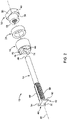
- FIGS. 1 and 2 illustrate a mandrel 10 (e.g., for a rotary tool or power tool).
- the mandrel 10 includes a shaft 14, a collar 18, and a fastener or nut 22.
- a washer 24 may be positioned between the collar 18 and the nut 22.
- the shaft 14 includes a proximal end or first end 26, a distal end or second end 30, and the shaft 14 extends along a longitudinal axis 34.
- the first end 26 is configured to be coupled to a motor (not shown) of the rotary tool and driven to rotate.
- the shaft 14 may be subjected to a hardening process.
- Locking projections 42 are positioned adjacent the second end 30. In the illustrated embodiment, two locking projections 42 are positioned on opposite sides of the longitudinal axis 34, and the locking projections 42 are positioned in a plane oriented perpendicular to the longitudinal axis 34 of the shaft 14.
- each of the locking projections 42 is positioned at a periphery of the second end 30 of the shaft 14, and tapers inwardly toward the longitudinal axis 34.
- an outer portion of each locking projection 42 has a trapezoidal profile.
- each of the locking projections 42 includes an outer planar surface 50, and planar sides 54 extend from the outer planar surface 50 inwardly toward one another.
- the width of each locking projection 42 increases as a radial distance from the longitudinal axis 34 increases.
- the locking projections 42 have a rectilinear profile, and are symmetric with respect to one another.
- the shaft 14 also includes a threaded portion 58 positioned proximate the locking projections 42.
- Planar portions 62 are positioned on opposite sides of the shaft 14 and extend along the threaded portion 58, dividing the threaded portion 58 into two separate threaded surfaces. The planar portions 62 of the shaft 14 are aligned between the planar sides 54 of separate locking projections 42.
- the collar 18 includes a first surface 70 positioned adjacent the locking projections 42.
- Coupling features are positioned on the first surface 70 of the collar 18.
- the coupling features includes a pair of coupling projections 74 positioned on opposite sides of the longitudinal axis 34 from one another.
- each of the coupling projections 74 has a trapezoidal profile.
- a narrow side 78 of the trapezoidal profile is positioned proximate the longitudinal axis 34, and a wide side 82 of the trapezoidal profile is positioned at a radial outer position.
- Inclined or tapered surfaces 84 extend between the narrow side 78 and the wide side 82.
- the narrow side 78 of the trapezoidal profile abuts one of the planar portions 62 of the shaft 14, limiting rotation of the collar 18 relative to the shaft 14.
- a distance between the narrow sides 78 of the coupling projections 74 is approximately equal to a distance between the planar portions 62 of the shaft 14.
- a distance between the wide sides 82 of the coupling projections 74 is approximately equal to a distance between the outer planar surfaces of the locking projections 42.
- the collar 18 includes a bore 86 through which a portion of the shaft 14 extends, and the collar 18 is slidable along the shaft 14.
- the coupling projections 74 are positioned between the locking projections 42,
- the coupling projections 74 are angularly offset from the locking projections 42 with respect to the axis 34.
- the coupling projections are angularly offset from the locking projections by ninety degrees, and the outermost edges of the coupling projections 74 and the locking projections 42 cooperate to form a substantially square or rectangular profile ( FIG. 3 ).
- the nut 22 is threadably coupled to the threaded portion 58 of the shaft 14.
- the nut 22 includes a threaded opening 90 through which a portion of the shaft 14 extends, and the nut 22 is positioned between the collar 18 and the second end 30 of the shaft 14.
- the nut 22 includes a base portion 92 and a neck portion 94 having a smaller diameter than the base portion 92.
- the base portion 92 may include one or more flat surfaces 96 to assist in rotating the nut 22.
- the neck portion 94 is received within a counterbore portion 98 ( FIG. 10 ) of the collar 18.
- the washer 24 may be positioned between the end surface of the collar 18 and the base portion 92 of the nut 22. Threading the nut 22 onto the shaft 14 causes the nut 22 to draw the collar 18 against the locking projections 42. Unthreading the nut 22 permits the collar 18 to be moved away from the locking projections 42.
- the threaded portion 58 and the threaded opening 90 may be oriented to inhibit the nut 22 loosening as the shaft 14 is driven to rotate. For example, the threaded portion 58 and the threaded opening 90 may engage one another via a left-hand thread. Alternatively, the threaded portion 58 and the threaded opening 90 may engage one another via a right-hand thread.
- an accessory 102 to be coupled to the shaft 14 includes an opening 106 that provides a mating interface with the mandrel and is similar in shape to the outer profile of the locking projections 42 and coupling projections 74.
- the opening 106 includes a first portion or intermediate portion 114 and two second portions or outer portions 110.
- the intermediate portion 114 is positioned between the outer portions 110 and is aligned with the longitudinal axis 34. Stated another way, the outer portions 110 are positioned adjacent a radially outward portion along a periphery of the intermediate portion 114.
- the outer portions 110 have a rectilinear profile that mirrors the shape of the outermost portions of the locking projections 42 and the coupling projections 74, while the intermediate portion 114 has an arcuate or round profile having a diameter that accommodates an outer diameter of the threaded portion 58 of the shaft 14.
- each of the outer portions 110 has a substantially trapezoidal shape. Stated another way, each of the outer portions 110 has an outermost edge 122 and a pair of tapered edges 126 extending from the outermost edge 122 toward the intermediate portion 114, and the tapered edges 126 extend toward one another from the outermost edge 122 to the intermediate portion 114.
- the accessory 102 is illustrated as a cutting disc; in other embodiments, the interface can be incorporated into another type of accessory.
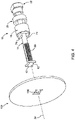
- the opening 106 of the accessory 102 is positioned as shown in FIG. 4 such that the outer portions 110 of the opening 106 are aligned with the locking projections 42.
- the collar 18 is positioned such that the coupling projections 74 are spaced apart from the locking projections 42 by an axial distance that is at least equal to a thickness of the accessory 102 proximate the opening 106.
- the accessory 102 is moved in a direction parallel to the longitudinal axis 34 such that the locking projections 42 pass through the opening 106 of the accessory 102.
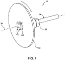
- the accessory 102 is then rotated about the longitudinal axis 34 as shown in FIG.
- the accessory 102 is rotated approximately 90 degrees.
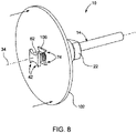
- the accessory 102 is then moved in a direction parallel to the longitudinal axis 34 as shown in FIG. 8 until the coupling projections 74 are positioned in the outer portions 110 of the accessory opening 106.
- the nut 22 is threaded relative to the shaft 14, thereby moving the collar 18 and the locking projections 42 toward one another.
- the accessory 102 may be uncoupled from the mandrel 10 by completing these steps in reverse order.
- the locking projections 42 secure the coupling projections 74 within the outer portions 110 of the opening 106.
- the coupling projections 74 may extend through the opening 106 such that a portion of the coupling projections 74 protrudes from the forward plane of the disc 102.
- FIGS. 11-15 illustrate a mandrel 410 according to another embodiment.
- the mandrel 410 is similar in some aspects to the mandrel 10 described with respect to FIGS. 1-10 , and similar features are identified with similar reference numbers, plus 400. Some similarities and differences of the mandrel 410 are described herein.
- the mandrel 410 includes a shaft 414, a collar 418, and a nut 422.
- a washer 424 may be positioned between the collar 418 and the nut 422.
- the shaft 414 includes a proximal end or first end 426, a distal end or second end 430, and the shaft 14 extends along a longitudinal axis 434.
- Locking projections 442 are positioned adjacent the second end 430. In the illustrated embodiment, two locking projections 442 are positioned on opposite sides of the longitudinal axis 434, and the locking projections 442 are positioned in a plane oriented perpendicular to the longitudinal axis 434 of the shaft 414.
- each of the locking projections 442 is positioned at a periphery of the second end 430 of the shaft 414.
- an outer portion of each locking projection 442 has a rectilinear profile, and specifically a rectangular profile.
- each of the locking projections 442 includes an outer planar surface 450.
- the sides 454 of each locking projections 442 is oriented perpendicular to the outer planar surface 450.
- the side 454 of one locking projection 442 is coplanar with a corresponding side of the other locking projection 442.
- the locking projections 42 are symmetric with respect to one another.
- the shaft 414 also includes a threaded portion 458 positioned proximate the locking projections 442.
- Planar portions 462 are positioned on opposite sides of the shaft 414 and extend along the threaded portion 458, dividing the threaded portion 458 into two separate threaded surfaces.
- the planar portions 462 of the shaft 414 are coplanar with the sides 454 ( FIG. 13 ) of the locking projections 42.
- the collar 418 includes a first surface 470 positioned adjacent the locking projections 442.
- Coupling features are positioned on the first surface 470 of the collar 418.
- the coupling features includes a pair of coupling projections 474 positioned on opposite sides of the longitudinal axis 434 from one another.
- the nut 422 is threadably coupled to the threaded portion 458 of the shaft 414.
- the nut 422 includes a threaded opening 490 through which a portion of the shaft 414 extends. Threading the nut 422 onto the shaft 414 causes the nut 422 to draw the collar 418 against the locking projections 442. Unthreading the nut 422 permits the collar 418 to be moved away from the locking projections 442.
- the threaded portion 458 and the threaded opening 490 may be oriented to inhibit the nut 422 loosening as the shaft 414 is driven to rotate. For example, the threaded portion 458 and the threaded opening 490 may engage one another via a left-hand thread. Alternatively, the threaded portion 458 and the threaded opening 490 may engage one another via a right-hand thread.
- each of the coupling projections 474 has a rectangular profile.
- An inner surface 478 of the rectangular profile is positioned proximate the longitudinal axis 434, and an outer surface 482 of the rectangular profile is positioned at a radial outer position.
- Side surfaces 484 extend between the inner surface 478 and the outer surface 482.
- the coupling projections 474 and the locking projections 442 cooperate to form a cross-shaped profile.
- each of the inner surfaces 478 abuts an associated one of the planar portions 462 of the shaft 414, limiting rotation of the collar 418 relative to the shaft 414.
- a distance between the inner surfaces 478 of the coupling projections 474 is approximately equal to a distance between the planar portions 462 of the shaft 414.
- a distance between the outer surfaces 482 of the coupling projections 474 is approximately equal to a distance between the outer planar sides 450 of the locking projections 442.
- an accessory 502 (e.g., a cutting disc) to be coupled to the shaft 414 includes an opening 506 that is similar in shape to the outer profile of the locking projections 442 and coupling projections 474.
- the opening 506 includes two outer portions 510 and an intermediate portion 514 positioned between the outer portions 510.
- the outer portions 510 have a rectilinear profile that mirrors the shape of the outermost portions of the locking projections 442 and the coupling projections 474 ( FIG. 13 ), while the intermediate portion 514 has an arcuate or round profile having a diameter that accommodates an outer diameter of the threaded portion 458 ( FIG. 12 ) of the shaft 414.
- the accessory 502 is illustrated as a cutting disc; in other embodiments, the interface can be incorporated into another type of accessory. It is understood that the accessory 502 can be coupled and uncoupled from the mandrel 410 in a similar manner as described and shown with respect to the mandrel 10.
Landscapes
- Engineering & Computer Science (AREA)
- Mechanical Engineering (AREA)
- Mutual Connection Of Rods And Tubes (AREA)
- Clamps And Clips (AREA)
Abstract
Description
- This application claims the benefit of prior-filed, co-pending
U.S. Provisional Patent Application No. 63/162,632, filed March 18, 2021 U.S. Provisional Patent Application No. 63/185,829, filed May 7, 2021 - The present disclosure relates to rotary tools, and more particularly to a connection interface for rotary tools.
- Rotary tools typically include a housing supporting a motor for driving a mandrel or bit holder. The mandrel may be capable of supporting various types of accessories (e.g., bits, discs) to perform various functions (e.g., cutting, sanding or polishing objects, drill holes, etc.).
- The present disclosure provides, in one independent aspect, a mandrel is provided for facilitating quick coupling and decoupling of an accessory to a rotary tool.
- In one independent aspect, a mandrel for a rotary tool includes a shaft, a locking projection, a collar coupled to the shaft, and a nut. The shaft extends along a longitudinal axis and includes a distal end. The locking projection is positioned adjacent the distal end of the shaft, and the locking projection protrudes radially relative to the longitudinal axis. The locking projection has a locking projection outer profile, and the locking projection outer profile is similar to a portion of a profile of a mating interface of an accessory. The collar includes a coupling feature, the coupling feature having a coupling outer profile that is similar to the locking projection outer profile. The nut is threadably coupled to the shaft to move the nut relative to the shaft along the longitudinal axis. Threading the nut causing the locking projection to move toward the coupling feature.
- In another independent aspect, a mandrel for a rotary tool includes a shaft, a pair of locking projections, a collar coupled to the shaft, and a fastener coupled to the shaft. The shaft extends along a longitudinal axis and includes a distal end. The pair of locking projections are positioned adjacent the distal end of the shaft. The locking projections protrude radially relative to the longitudinal axis and are positioned on opposite sides of the longitudinal axis from one another. Each of the locking projections defines a locking projection outer profile configured to be similar to a portion of a profile of a mating interface of an accessory. The locking projection outer profile is rectilinear. The collar includes a pair of coupling projections protruding from a surface of the collar adjacent the distal end of the shaft. The coupling projections are angularly offset from the locking projections with respect to the longitudinal axis. Each of the coupling projections define a coupling projection outer profile configured to be similar to the portion of the profile of a mating interface of the accessory. The coupling projection outer profile is rectilinear. The fastener is movable relative to the shaft along the longitudinal axis, and movement of the fastener causing the locking projections to move toward the coupling projections.
- In yet another independent aspect, an accessory for a rotary tool includes a cutting edge, and a mating interface configured to secure the accessory to a mandrel. The mating interface includes an opening having a first portion and a pair of second portions. The first portion is aligned with an axis of rotation, and the first portion having an arcuate profile. The second portions are positioned on opposite sides of the axis from one another. Each of the second portions is positioned adjacent a radially outward position along a periphery of the first portion, and each of the second portions has a rectilinear profile.
- Other features and aspects of the disclosure will become apparent by consideration of the following detailed description and accompanying drawings.
-
-
FIG. 1 is a perspective view of a mandrel. -
FIG. 2 is an exploded view of the mandrel ofFIG. 1 -
FIG. 3 is an end view of the mandrel ofFIG. 1 in a locked position. -
FIG. 4 is a perspective view of the mandrel ofFIG. 1 and an accessory. -
FIG. 5 is an end view of the accessory ofFIG. 4 . -
FIG. 6 is a perspective view of the mandrel and accessory ofFIG. 2 , with the accessory in a first position. -
FIG. 7 is a perspective view of the mandrel and accessory ofFIG. 2 , with the accessory in a second position. -
FIG. 8 is a perspective view of the mandrel and accessory ofFIG. 2 , with the accessory in a third position. -
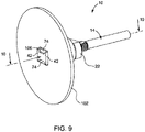
FIG. 9 is a perspective view of the mandrel and accessory ofFIG. 2 , with the accessory secured to the mandrel. -
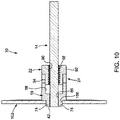
FIG. 10 is a section view of the mandrel and accessory ofFIG. 9 , viewed alongsection 10--10. -
FIG. 11 is a perspective view of a mandrel according to another embodiment. -
FIG. 12 is an exploded view of the mandrel ofFIG. 11 . -
FIG. 13 is an end view of the mandrel ofFIG. 11 in a locked position. -
FIG. 14 is a perspective view of the mandrel ofFIG. 11 , and an accessory according to another embodiment. -
FIG. 15 is a plan view of the accessory ofFIG. 14 . - Before any embodiments of the disclosure are explained in detail, it is to be understood that the disclosure is not limited in its application to the details of construction and the arrangement of components set forth in the following description or illustrated in the following drawings. The disclosure is capable of other embodiments and of being practiced or of being carried out in various ways. Also, it is to be understood that the phraseology and terminology used herein is for the purpose of description and should not be regarded as limiting. Use of "including" and "comprising" and variations thereof as used herein is meant to encompass the items listed thereafter and equivalents thereof as well as additional items. Unless specified or limited otherwise, the terms "mounted," "connected," "supported," and "coupled" and variations thereof are used broadly and encompass both direct and indirect mountings, connections, supports, and couplings.
-
FIGS. 1 and2 illustrate a mandrel 10 (e.g., for a rotary tool or power tool). In the illustrated embodiment, themandrel 10 includes ashaft 14, acollar 18, and a fastener ornut 22. In some embodiments, awasher 24 may be positioned between thecollar 18 and thenut 22. Theshaft 14 includes a proximal end orfirst end 26, a distal end orsecond end 30, and theshaft 14 extends along alongitudinal axis 34. Thefirst end 26 is configured to be coupled to a motor (not shown) of the rotary tool and driven to rotate. Theshaft 14 may be subjected to a hardening process.Locking projections 42 are positioned adjacent thesecond end 30. In the illustrated embodiment, twolocking projections 42 are positioned on opposite sides of thelongitudinal axis 34, and thelocking projections 42 are positioned in a plane oriented perpendicular to thelongitudinal axis 34 of theshaft 14. - As shown in
FIG. 3 , each of thelocking projections 42 is positioned at a periphery of thesecond end 30 of theshaft 14, and tapers inwardly toward thelongitudinal axis 34. In some embodiments, an outer portion of eachlocking projection 42 has a trapezoidal profile. Stated another way, each of the lockingprojections 42 includes an outerplanar surface 50, andplanar sides 54 extend from the outerplanar surface 50 inwardly toward one another. The width of each lockingprojection 42 increases as a radial distance from thelongitudinal axis 34 increases. The lockingprojections 42 have a rectilinear profile, and are symmetric with respect to one another. - Referring again to
FIG. 2 , in the illustrated embodiment, theshaft 14 also includes a threadedportion 58 positioned proximate the lockingprojections 42.Planar portions 62 are positioned on opposite sides of theshaft 14 and extend along the threadedportion 58, dividing the threadedportion 58 into two separate threaded surfaces. Theplanar portions 62 of theshaft 14 are aligned between theplanar sides 54 ofseparate locking projections 42. - As shown in
FIG. 2 , thecollar 18 includes afirst surface 70 positioned adjacent the lockingprojections 42. Coupling features are positioned on thefirst surface 70 of thecollar 18. In the illustrated embodiment, the coupling features includes a pair ofcoupling projections 74 positioned on opposite sides of thelongitudinal axis 34 from one another. - As best shown in
FIG. 3 , in the illustrated embodiment, each of thecoupling projections 74 has a trapezoidal profile. Anarrow side 78 of the trapezoidal profile is positioned proximate thelongitudinal axis 34, and awide side 82 of the trapezoidal profile is positioned at a radial outer position. Inclined ortapered surfaces 84 extend between thenarrow side 78 and thewide side 82. When an accessory 102 (FIG. 4 ) is secured on themandrel 10, thewide sides 82 and thetapered surfaces 84 of thecoupling projections 74 transmit torque to theaccessory 102 to rotate theaccessory 102. Thecoupling projections 74 are aligned between the locking projections 42 (for example, betweenplanar sides 54 of separate locking projections 42). In the illustrated embodiment, thenarrow side 78 of the trapezoidal profile abuts one of theplanar portions 62 of theshaft 14, limiting rotation of thecollar 18 relative to theshaft 14. A distance between thenarrow sides 78 of thecoupling projections 74 is approximately equal to a distance between theplanar portions 62 of theshaft 14. A distance between thewide sides 82 of thecoupling projections 74 is approximately equal to a distance between the outer planar surfaces of the lockingprojections 42. - The
collar 18 includes abore 86 through which a portion of theshaft 14 extends, and thecollar 18 is slidable along theshaft 14. When thecollar 18 is moved to abut the lockingprojections 42, thecoupling projections 74 are positioned between the lockingprojections 42, Thecoupling projections 74 are angularly offset from the lockingprojections 42 with respect to theaxis 34. In the illustrated embodiment the coupling projections are angularly offset from the locking projections by ninety degrees, and the outermost edges of thecoupling projections 74 and the lockingprojections 42 cooperate to form a substantially square or rectangular profile (FIG. 3 ). - As shown in
FIG. 2 , thenut 22 is threadably coupled to the threadedportion 58 of theshaft 14. In the illustrated embodiment, thenut 22 includes a threadedopening 90 through which a portion of theshaft 14 extends, and thenut 22 is positioned between thecollar 18 and thesecond end 30 of theshaft 14. In the illustrated embodiment, thenut 22 includes abase portion 92 and aneck portion 94 having a smaller diameter than thebase portion 92. Thebase portion 92 may include one or moreflat surfaces 96 to assist in rotating thenut 22. As thenut 22 is threaded, theneck portion 94 is received within a counterbore portion 98 (FIG. 10 ) of thecollar 18. Thewasher 24 may be positioned between the end surface of thecollar 18 and thebase portion 92 of thenut 22. Threading thenut 22 onto theshaft 14 causes thenut 22 to draw thecollar 18 against the lockingprojections 42. Unthreading thenut 22 permits thecollar 18 to be moved away from the lockingprojections 42. In some embodiments, the threadedportion 58 and the threadedopening 90 may be oriented to inhibit thenut 22 loosening as theshaft 14 is driven to rotate. For example, the threadedportion 58 and the threadedopening 90 may engage one another via a left-hand thread. Alternatively, the threadedportion 58 and the threadedopening 90 may engage one another via a right-hand thread. - As shown in
FIGS. 4 and5 , an accessory 102 (e.g., a cutting disc) to be coupled to theshaft 14 includes anopening 106 that provides a mating interface with the mandrel and is similar in shape to the outer profile of the lockingprojections 42 andcoupling projections 74. As shown inFIG. 5 , in the illustrated embodiment, theopening 106 includes a first portion orintermediate portion 114 and two second portions orouter portions 110. Theintermediate portion 114 is positioned between theouter portions 110 and is aligned with thelongitudinal axis 34. Stated another way, theouter portions 110 are positioned adjacent a radially outward portion along a periphery of theintermediate portion 114. Theouter portions 110 have a rectilinear profile that mirrors the shape of the outermost portions of the lockingprojections 42 and thecoupling projections 74, while theintermediate portion 114 has an arcuate or round profile having a diameter that accommodates an outer diameter of the threadedportion 58 of theshaft 14. - In the illustrated embodiments, a radially outermost edge of each of the
outer portions 110 has a substantially trapezoidal shape. Stated another way, each of theouter portions 110 has anoutermost edge 122 and a pair of taperededges 126 extending from theoutermost edge 122 toward theintermediate portion 114, and the taperededges 126 extend toward one another from theoutermost edge 122 to theintermediate portion 114. In the illustrated embodiment, theaccessory 102 is illustrated as a cutting disc; in other embodiments, the interface can be incorporated into another type of accessory. - To couple the accessory 102 to the
shaft 14, theopening 106 of theaccessory 102 is positioned as shown inFIG. 4 such that theouter portions 110 of theopening 106 are aligned with the lockingprojections 42. In addition, thecollar 18 is positioned such that thecoupling projections 74 are spaced apart from the lockingprojections 42 by an axial distance that is at least equal to a thickness of theaccessory 102 proximate theopening 106. As shown inFIG. 6 , theaccessory 102 is moved in a direction parallel to thelongitudinal axis 34 such that the lockingprojections 42 pass through theopening 106 of theaccessory 102. Theaccessory 102 is then rotated about thelongitudinal axis 34 as shown inFIG. 7 so that theouter portions 110 of theaccessory 102opening 106 are axially aligned with thecoupling projections 74 of thecollar 18. In the illustrated embodiment, theaccessory 102 is rotated approximately 90 degrees. Theaccessory 102 is then moved in a direction parallel to thelongitudinal axis 34 as shown inFIG. 8 until thecoupling projections 74 are positioned in theouter portions 110 of theaccessory opening 106. Finally, thenut 22 is threaded relative to theshaft 14, thereby moving thecollar 18 and the lockingprojections 42 toward one another. Theaccessory 102 may be uncoupled from themandrel 10 by completing these steps in reverse order. - As shown in
FIGS. 9 and10 , the lockingprojections 42 secure thecoupling projections 74 within theouter portions 110 of theopening 106. In some embodiments, thecoupling projections 74 may extend through theopening 106 such that a portion of thecoupling projections 74 protrudes from the forward plane of thedisc 102. -
FIGS. 11-15 illustrate amandrel 410 according to another embodiment. Themandrel 410 is similar in some aspects to themandrel 10 described with respect toFIGS. 1-10 , and similar features are identified with similar reference numbers, plus 400. Some similarities and differences of themandrel 410 are described herein. - As shown in
FIGS. 11-12 , themandrel 410 includes ashaft 414, acollar 418, and anut 422. In some embodiments, awasher 424 may be positioned between thecollar 418 and thenut 422. Theshaft 414 includes a proximal end orfirst end 426, a distal end orsecond end 430, and theshaft 14 extends along alongitudinal axis 434. Lockingprojections 442 are positioned adjacent thesecond end 430. In the illustrated embodiment, two lockingprojections 442 are positioned on opposite sides of thelongitudinal axis 434, and the lockingprojections 442 are positioned in a plane oriented perpendicular to thelongitudinal axis 434 of theshaft 414. - As shown in
FIG. 13 , each of the lockingprojections 442 is positioned at a periphery of thesecond end 430 of theshaft 414. In the illustrated embodiment, an outer portion of each lockingprojection 442 has a rectilinear profile, and specifically a rectangular profile. Stated another way, each of the lockingprojections 442 includes an outerplanar surface 450. Thesides 454 of each lockingprojections 442 is oriented perpendicular to the outerplanar surface 450. In the illustrated embodiment, theside 454 of onelocking projection 442 is coplanar with a corresponding side of theother locking projection 442. The lockingprojections 42 are symmetric with respect to one another. - Referring again to
FIG. 12 , in the illustrated embodiment, theshaft 414 also includes a threadedportion 458 positioned proximate the lockingprojections 442.Planar portions 462 are positioned on opposite sides of theshaft 414 and extend along the threadedportion 458, dividing the threadedportion 458 into two separate threaded surfaces. In the illustrated embodiment, theplanar portions 462 of theshaft 414 are coplanar with the sides 454 (FIG. 13 ) of the lockingprojections 42. - As shown in
FIG. 12 , thecollar 418 includes afirst surface 470 positioned adjacent the lockingprojections 442. Coupling features are positioned on thefirst surface 470 of thecollar 418. In the illustrated embodiment, the coupling features includes a pair ofcoupling projections 474 positioned on opposite sides of thelongitudinal axis 434 from one another. - As shown in
FIGS. 11 and12 , thenut 422 is threadably coupled to the threadedportion 458 of theshaft 414. In the illustrated embodiment, thenut 422 includes a threadedopening 490 through which a portion of theshaft 414 extends. Threading thenut 422 onto theshaft 414 causes thenut 422 to draw thecollar 418 against the lockingprojections 442. Unthreading thenut 422 permits thecollar 418 to be moved away from the lockingprojections 442. In some embodiments, the threadedportion 458 and the threadedopening 490 may be oriented to inhibit thenut 422 loosening as theshaft 414 is driven to rotate. For example, the threadedportion 458 and the threadedopening 490 may engage one another via a left-hand thread. Alternatively, the threadedportion 458 and the threadedopening 490 may engage one another via a right-hand thread. - As best shown in
FIG. 13 , in the illustrated embodiment, each of thecoupling projections 474 has a rectangular profile. Aninner surface 478 of the rectangular profile is positioned proximate thelongitudinal axis 434, and anouter surface 482 of the rectangular profile is positioned at a radial outer position. Side surfaces 484 extend between theinner surface 478 and theouter surface 482. When an accessory 502 (FIG. 14 ) is secured on themandrel 410, theouter surfaces 482 and the side surfaces 484 of thecoupling projections 474 transmit torque to theaccessory 502 to rotate theaccessory 502. Thecoupling projections 474 are angularly offset from the lockingprojections 442 with respect to theaxis 434. Thecoupling projections 474 and the lockingprojections 442 cooperate to form a cross-shaped profile. In the illustrated embodiment, each of theinner surfaces 478 abuts an associated one of theplanar portions 462 of theshaft 414, limiting rotation of thecollar 418 relative to theshaft 414. A distance between theinner surfaces 478 of thecoupling projections 474 is approximately equal to a distance between theplanar portions 462 of theshaft 414. A distance between theouter surfaces 482 of thecoupling projections 474 is approximately equal to a distance between the outerplanar sides 450 of the lockingprojections 442. - As shown in
FIGS. 14 and15 , an accessory 502 (e.g., a cutting disc) to be coupled to theshaft 414 includes anopening 506 that is similar in shape to the outer profile of the lockingprojections 442 andcoupling projections 474. As shown inFIG. 15 , in the illustrated embodiment, theopening 506 includes twoouter portions 510 and anintermediate portion 514 positioned between theouter portions 510. Theouter portions 510 have a rectilinear profile that mirrors the shape of the outermost portions of the lockingprojections 442 and the coupling projections 474 (FIG. 13 ), while theintermediate portion 514 has an arcuate or round profile having a diameter that accommodates an outer diameter of the threaded portion 458 (FIG. 12 ) of theshaft 414. In the illustrated embodiment, theaccessory 502 is illustrated as a cutting disc; in other embodiments, the interface can be incorporated into another type of accessory. It is understood that theaccessory 502 can be coupled and uncoupled from themandrel 410 in a similar manner as described and shown with respect to themandrel 10. - Although aspects have been described in detail with reference to certain embodiments, variations and modifications exist within the scope of one or more independent aspects as described.
Claims (15)
- A mandrel for a rotary tool, the mandrel comprising:a shaft extending along a longitudinal axis and including a distal end;a locking projection positioned adjacent the distal end of the shaft, the locking projection protruding radially relative to the longitudinal axis, the locking projection having a locking projection outer profile that is similar to a portion of a profile of a mating interface of an accessory;a collar coupled to the shaft, the collar including a coupling feature, the coupling feature having a coupling outer profile that is similar to the locking projection outer profile; anda nut threadably coupled to the shaft to move the nut relative to the shaft along the longitudinal axis, threading the nut causing the locking projection to move toward the coupling feature.
- The mandrel of claim 1, wherein the locking projection includes a pair of locking projections positioned in a plane oriented perpendicular to a longitudinal axis of the shaft, each of the locking projections having a rectilinear outer profile.
- The mandrel of claim 1, wherein the locking projection includes a pair of locking projections positioned on opposite sides of the longitudinal axis from one another, each of the locking projections having a trapezoidal outer profile, wherein the coupling feature includes a pair of trapezoidal coupling projections positioned on opposite sides of the longitudinal axis from one another, the coupling projections being angularly offset from the locking projections by ninety degrees with respect to the longitudinal axis.
- The mandrel of any one of the preceding claims, wherein the coupling feature includes a pair of trapezoidal coupling projections positioned on opposite sides of the longitudinal axis from one another, the coupling projections being angularly offset from the locking projection with respect to the longitudinal axis of the shaft, the coupling projections and the locking projection cooperating to form a rectangular outer profile while the locking projection is drawn against the coupling projections.
- The mandrel of any one of claims 1 to 3, wherein the coupling feature includes a pair of rectangular coupling projections positioned on opposite sides of the longitudinal axis from one another, the coupling projections being angularly offset from the locking projection with respect to the longitudinal axis of the shaft, the coupling projections and the locking projection cooperating to form a cross-shaped outer profile while the locking projection is drawn against the coupling projections.
- The mandrel of claim 1-wherein the locking projection is one of_a pair of locking projections positioned on opposite sides of the longitudinal axis from one another, wherein the locking projection outer profile is rectilinear;
wherein the collar includes a pair of coupling projections protruding from a surface of the collar adjacent the distal end of the shaft, the coupling projections angularly offset from the locking projections with respect to the longitudinal axis, the coupling projection outer profile configured to be similar to the portion of the profile of a mating interface of the accessory, the coupling projection outer profile being rectilinear. - The mandrel of claim 6, wherein the locking projections are positioned in a plane oriented perpendicular to a longitudinal axis of the shaft.
- The mandrel of any one of claim 2, 6, or 7, wherein each of the locking projections has a rectangular outer profile.
- The mandrel of any one of claims 6 to 8, wherein each of the coupling projections has a rectangular outer profile, the coupling projections angularly offset from the locking projections by ninety degrees with respect to the longitudinal axis.
- The mandrel of any one of claims 2, 6, or 7, wherein each of the locking projections has a trapezoidal outer profile, and optionally, wherein each of the coupling projections has a trapezoidal outer profile that is complementary to the trapezoidal outer profile of the locking projections, the coupling projections angularly offset from the locking projections by ninety degrees with respect to the longitudinal axis.
- The mandrel of any one of the preceding claims, wherein the shaft and the nut engage one another via a left hand thread.
- An accessory for a rotary tool, the accessory comprising:a cutting edge; anda mating interface configured to secure the accessory to a mandrel, the mating interface including an opening having a first portion and a pair of second portions, the first portion aligned with an axis of rotation, the first portion having an arcuate profile, the second portions positioned on opposite sides of the axis from one another, each of the second portions positioned adjacent a radially outward position along a periphery of the first portion, each of the second portions having a rectilinear profile.
- The accessory of claim 12, wherein an outer perimeter of each of the second portions has a substantially rectangular shape.
- The accessory of claim 12, wherein an outer perimeter of each of the second portions has a substantially trapezoidal shape.
- The accessory of claim 12 or claim 14, wherein each of the second portions has a radially outermost edge and a pair of tapered edges extending from the outermost edge toward the first portion, wherein the tapered edges extend toward one another from the outermost edge to the first portion.
Applications Claiming Priority (2)
| Application Number | Priority Date | Filing Date | Title |
|---|---|---|---|
| US202163162632P | 2021-03-18 | 2021-03-18 | |
| US202163185829P | 2021-05-07 | 2021-05-07 |
Publications (1)
| Publication Number | Publication Date |
|---|---|
| EP4108381A1 true EP4108381A1 (en) | 2022-12-28 |
Family
ID=80819951
Family Applications (1)
| Application Number | Title | Priority Date | Filing Date |
|---|---|---|---|
| EP22163098.1A Pending EP4108381A1 (en) | 2021-03-18 | 2022-03-18 | Mandrel and accessory for rotary tool |
Country Status (5)
| Country | Link |
|---|---|
| US (1) | US12179309B2 (en) |
| EP (1) | EP4108381A1 (en) |
| CN (1) | CN217942669U (en) |
| CA (1) | CA3152398A1 (en) |
| MX (1) | MX2022003314A (en) |
Families Citing this family (2)
| Publication number | Priority date | Publication date | Assignee | Title |
|---|---|---|---|---|
| USD1102495S1 (en) * | 2022-03-16 | 2025-11-18 | Techtronic Cordless Gp | Mandrel |
| USD1130042S1 (en) | 2022-03-16 | 2026-06-16 | Techtronic Cordless Gp | Cutting disc |
Citations (3)
| Publication number | Priority date | Publication date | Assignee | Title |
|---|---|---|---|---|
| US1941840A (en) * | 1930-11-03 | 1934-01-02 | William A Kelsey | Tool clamp |
| US20050135886A1 (en) * | 2003-10-23 | 2005-06-23 | Scheuerman Michael L. | Arbor arrangement |
| EP1745889A1 (en) * | 2005-07-21 | 2007-01-24 | Robert Bosch Gmbh | Accessory for a rotary tool |
Family Cites Families (53)
| Publication number | Priority date | Publication date | Assignee | Title |
|---|---|---|---|---|
| US3197219A (en) * | 1964-01-06 | 1965-07-27 | Bridgeport Machines | Geared-key supported jawless quick release chuck |
| US3623281A (en) | 1969-06-16 | 1971-11-30 | Robert H Moffat | Mounting fixture |
| US3679220A (en) * | 1970-03-23 | 1972-07-25 | Portage Machine Co | Quick change tool holder |
| US5061129A (en) * | 1990-08-01 | 1991-10-29 | The Cross Company | Clamping arrangement for a cutting tool |
| US5407293A (en) * | 1993-04-29 | 1995-04-18 | Crainich; Lawrence | Coupling apparatus for medical instrument |
| US5667228A (en) * | 1995-06-20 | 1997-09-16 | Fabris; Mario | Quick change mandrel for an engine lathe etc |
| SE510981C2 (en) | 1996-05-07 | 1999-07-19 | Atlas Copco Tools Ab | Portable grinding machine with interchangeable wear part |
| US6254303B1 (en) * | 1999-02-01 | 2001-07-03 | Bogdan S. Falat | Quick-release connector and methods therefore |
| DE10061559A1 (en) | 2000-12-07 | 2002-06-13 | C & E Fein Gmbh & Co Kg | Holder for attaching a tool to a drive shaft and adapter for this |
| US6945862B2 (en) | 2000-12-07 | 2005-09-20 | C. & E. Fein Gmbh | Power tool having a receptacle for securing a tool |
| DE10360246A1 (en) | 2003-12-20 | 2005-07-28 | Robert Bosch Gmbh | Insert tool for a machine tool |
| DE10361810A1 (en) | 2003-12-30 | 2005-07-28 | Robert Bosch Gmbh | Hand tool with clamping device |
| US7387563B2 (en) | 2005-07-21 | 2008-06-17 | Robert Bosch Gmbh | Mandrel and accessory and related combination for use with a rotary tool |
| DE102006001986A1 (en) | 2006-01-16 | 2007-07-19 | Robert Bosch Gmbh | Clamping device for releasably securing a disc-shaped tool |
| US7614940B2 (en) | 2006-03-23 | 2009-11-10 | Robert Bosch Gmbh | Accessory with hub for use with multiple types of rotary tool mandrels |
| DE102007055777A1 (en) | 2007-12-12 | 2009-06-18 | Hilti Aktiengesellschaft | Hand tool with clamping nut |
| EP2403685B1 (en) | 2008-01-07 | 2015-05-06 | Lachlan George Reid | Attachment mechanism for a cutting disc |
| DE202008011959U1 (en) | 2008-08-29 | 2010-02-11 | C. & E. Fein Gmbh | Adapter for attaching a tool to an oscillating drive |
| US20100263932A1 (en) * | 2009-04-16 | 2010-10-21 | Dale Richard Wolfer | Bit retainer assembly for a down-hole drill |
| US20110266759A1 (en) | 2010-04-29 | 2011-11-03 | Black & Decker Inc. | Oscillating tool |
| US8925931B2 (en) | 2010-04-29 | 2015-01-06 | Black & Decker Inc. | Oscillating tool |
| US20130193655A1 (en) | 2010-04-29 | 2013-08-01 | Black & Decker Inc. | Oscillating Tool Adapter |
| US9186770B2 (en) | 2010-04-29 | 2015-11-17 | Black & Decker Inc. | Oscillating tool attachment feature |
| DE102010043190A1 (en) | 2010-10-29 | 2012-05-03 | Robert Bosch Gmbh | Hand machine tool fixture |
| DE102010064363B4 (en) | 2010-12-30 | 2021-12-16 | Robert Bosch Gmbh | Hand tool clamping device with anti-twist protection |
| US9067293B2 (en) | 2011-09-30 | 2015-06-30 | Robert Bosch Gmbh | Accessory clamp for a power tool |
| DE102011084499A1 (en) * | 2011-10-14 | 2013-04-18 | Robert Bosch Gmbh | tool attachment |
| JP5718207B2 (en) | 2011-10-19 | 2015-05-13 | 株式会社マキタ | Work tools |
| JP2013094905A (en) | 2011-11-01 | 2013-05-20 | Makita Corp | Working tool |
| DE102012004457A1 (en) | 2012-03-08 | 2013-09-12 | Robert Bosch Gmbh | application tool |
| DE102012004458A1 (en) | 2012-03-08 | 2013-09-12 | Robert Bosch Gmbh | tool holder |
| DE102012007930A1 (en) | 2012-04-17 | 2013-10-17 | C. & E. Fein Gmbh | Power-driven hand tool has receiving portion which is adapted to mounting opening of tool such that defined relative rotation between tool and fastening element around longitudinal axis causes axial release safety of tool |
| DE102012222617A1 (en) * | 2012-12-10 | 2014-06-12 | Robert Bosch Gmbh | Shaft for rotational coupling of a main device with a tubular device |
| DE102012222627B4 (en) | 2012-12-10 | 2021-11-04 | Robert Bosch Gmbh | Tubular device for connection to a shaft |
| SE537043C2 (en) * | 2013-04-11 | 2014-12-16 | Sandvik Intellectual Property | First coupling part and tool coupling |
| KR101483963B1 (en) | 2014-11-25 | 2015-01-20 | 김창성 | Attachable device for hand grinding polishing disk |
| US9796064B2 (en) | 2015-02-19 | 2017-10-24 | GM Global Technology Operations LLC | Quick change adapter for grinding wheels |
| EP3202533A1 (en) | 2016-02-02 | 2017-08-09 | HILTI Aktiengesellschaft | Clamping device |
| DE102017213669A1 (en) * | 2016-08-22 | 2018-02-22 | Robert Bosch Gmbh | Tool device for a hand tool |
| US10682714B2 (en) | 2016-08-31 | 2020-06-16 | Robert Bosch Tool Corporation | Oscillating interface for an oscillating power tool |
| WO2018110856A1 (en) | 2016-12-16 | 2018-06-21 | 주식회사 미래텍 | Rotation device |
| KR101783562B1 (en) | 2016-12-21 | 2017-10-10 | 이장희 | Abrasive disk with fixing holder fixtures |
| KR101773447B1 (en) | 2017-01-16 | 2017-08-31 | 주식회사 이엔큐원터치 | Connecting method of polishing disk combined with hand grinder |
| KR101838740B1 (en) | 2017-06-09 | 2018-04-30 | 김점용 | Fixing assembly and grinder having a grinding blade |
| DE102017214117B4 (en) | 2017-08-11 | 2026-02-26 | Robert Bosch Gmbh | Quick-release clamping device |
| KR20190027506A (en) | 2017-09-07 | 2019-03-15 | (주)태룡 | hand grinder |
| US10517212B2 (en) | 2017-10-03 | 2019-12-31 | Deere & Company | Quick attach rotary mower blade system |
| EP3476539A1 (en) | 2017-10-27 | 2019-05-01 | HILTI Aktiengesellschaft | Tensioning device and handheld machine tool |
| DE102019206810A1 (en) | 2018-05-31 | 2019-12-05 | Bosch Limited | A holding arrangement for a circular saw tool |
| WO2020009305A1 (en) | 2018-07-02 | 2020-01-09 | 주식회사 미래텍 | Torque transmission device |
| CN109623653B (en) | 2018-12-20 | 2020-04-24 | 厉畅 | Quick installation mechanism of trigeminy emery wheel |
| CN211639397U (en) | 2020-01-19 | 2020-10-09 | 重庆艺淳义齿制作有限公司 | A handheld denture grinding device that can quickly replace grinding heads |
| CN111890223A (en) | 2020-07-14 | 2020-11-06 | 张家港市创基机械设备制造有限公司 | A Quick Installation Mechanism for Grinding Heads on Sand Mills |
-
2022
- 2022-03-16 CA CA3152398A patent/CA3152398A1/en active Pending
- 2022-03-16 US US17/696,713 patent/US12179309B2/en active Active
- 2022-03-17 MX MX2022003314A patent/MX2022003314A/en unknown
- 2022-03-17 CN CN202220590371.XU patent/CN217942669U/en active Active
- 2022-03-18 EP EP22163098.1A patent/EP4108381A1/en active Pending
Patent Citations (3)
| Publication number | Priority date | Publication date | Assignee | Title |
|---|---|---|---|---|
| US1941840A (en) * | 1930-11-03 | 1934-01-02 | William A Kelsey | Tool clamp |
| US20050135886A1 (en) * | 2003-10-23 | 2005-06-23 | Scheuerman Michael L. | Arbor arrangement |
| EP1745889A1 (en) * | 2005-07-21 | 2007-01-24 | Robert Bosch Gmbh | Accessory for a rotary tool |
Also Published As
| Publication number | Publication date |
|---|---|
| US20220297202A1 (en) | 2022-09-22 |
| MX2022003314A (en) | 2022-09-19 |
| US12179309B2 (en) | 2024-12-31 |
| CN217942669U (en) | 2022-12-02 |
| CA3152398A1 (en) | 2022-09-18 |
Similar Documents
| Publication | Publication Date | Title |
|---|---|---|
| US10702927B2 (en) | Accessories for oscillating power tools | |
| KR100888041B1 (en) | Tool assembly | |
| US7077736B2 (en) | Angle attachment for power tool | |
| JP6767570B2 (en) | Tool equipment, how to use tool equipment, how to manufacture tool equipment, and machine tool systems | |
| US20220297202A1 (en) | Mandrel and accessory for rotary tool | |
| US6401837B1 (en) | Charging type multipurpose combination tool | |
| CN100496832C (en) | Tool connector for rotary tools | |
| JP2002511027A (en) | Tool system that can be connected to the drive shaft of rotating machinery | |
| EP1034870A2 (en) | Saw blade and mounting device for same | |
| US10730118B2 (en) | Rotatable cutting tool and key therefor | |
| US9623491B2 (en) | Beveling / chamfering tool—router head for metal | |
| CN201271840Y (en) | Rotary connector for suction tube of surface working tool | |
| KR20200088230A (en) | Spring loaded adjustable head | |
| US3736011A (en) | Quick disconnect tool coupling | |
| US20050135886A1 (en) | Arbor arrangement | |
| US4269421A (en) | Floating tool holder | |
| CN102785161A (en) | power tool | |
| US4111442A (en) | Floating tool holder | |
| US8079789B2 (en) | Tool coupling | |
| US7448834B2 (en) | Tool clamping device | |
| US6405807B1 (en) | Alternating direct current multipurpose combination tool | |
| US5325742A (en) | Hydraulic torque wrench drive shaft retainer | |
| KR102407300B1 (en) | Handle Device and Drilling Machine | |
| TW201742700A (en) | Assembly structure of machining tool capable of tightly combining assembly portion of machining head with clamping holder even though having some deviations therebetween | |
| US20220364606A1 (en) | Threaded tapered fastener for securing a power transmission device to a shaft |
Legal Events
| Date | Code | Title | Description |
|---|---|---|---|
| PUAI | Public reference made under article 153(3) epc to a published international application that has entered the european phase |
Free format text: ORIGINAL CODE: 0009012 |
|
| STAA | Information on the status of an ep patent application or granted ep patent |
Free format text: STATUS: THE APPLICATION HAS BEEN PUBLISHED |
|
| AK | Designated contracting states |
Kind code of ref document: A1 Designated state(s): AL AT BE BG CH CY CZ DE DK EE ES FI FR GB GR HR HU IE IS IT LI LT LU LV MC MK MT NL NO PL PT RO RS SE SI SK SM TR |
|
| STAA | Information on the status of an ep patent application or granted ep patent |
Free format text: STATUS: REQUEST FOR EXAMINATION WAS MADE |
|
| 17P | Request for examination filed |
Effective date: 20230627 |
|
| RBV | Designated contracting states (corrected) |
Designated state(s): AL AT BE BG CH CY CZ DE DK EE ES FI FR GB GR HR HU IE IS IT LI LT LU LV MC MK MT NL NO PL PT RO RS SE SI SK SM TR |
|
| STAA | Information on the status of an ep patent application or granted ep patent |
Free format text: STATUS: EXAMINATION IS IN PROGRESS |
|
| 17Q | First examination report despatched |
Effective date: 20251006 |