EP4108309A1 - Outdoor air purifier comprising at least one filter element, filter element for such an air purifier and use of a filter element - Google Patents
Outdoor air purifier comprising at least one filter element, filter element for such an air purifier and use of a filter element Download PDFInfo
- Publication number
- EP4108309A1 EP4108309A1 EP21181814.1A EP21181814A EP4108309A1 EP 4108309 A1 EP4108309 A1 EP 4108309A1 EP 21181814 A EP21181814 A EP 21181814A EP 4108309 A1 EP4108309 A1 EP 4108309A1
- Authority
- EP
- European Patent Office
- Prior art keywords
- air purifier
- outdoor air
- filter element
- housing
- fan
- Prior art date
- Legal status (The legal status is an assumption and is not a legal conclusion. Google has not performed a legal analysis and makes no representation as to the accuracy of the status listed.)
- Pending
Links
Images






Classifications
-
- B—PERFORMING OPERATIONS; TRANSPORTING
- B01—PHYSICAL OR CHEMICAL PROCESSES OR APPARATUS IN GENERAL
- B01D—SEPARATION
- B01D46/00—Filters or filtering processes specially modified for separating dispersed particles from gases or vapours
- B01D46/0002—Casings; Housings; Frame constructions
- B01D46/0005—Mounting of filtering elements within casings, housings or frames
-
- B—PERFORMING OPERATIONS; TRANSPORTING
- B01—PHYSICAL OR CHEMICAL PROCESSES OR APPARATUS IN GENERAL
- B01D—SEPARATION
- B01D46/00—Filters or filtering processes specially modified for separating dispersed particles from gases or vapours
- B01D46/24—Particle separators, e.g. dust precipitators, using rigid hollow filter bodies
- B01D46/2403—Particle separators, e.g. dust precipitators, using rigid hollow filter bodies characterised by the physical shape or structure of the filtering element
- B01D46/2411—Filter cartridges
-
- B—PERFORMING OPERATIONS; TRANSPORTING
- B01—PHYSICAL OR CHEMICAL PROCESSES OR APPARATUS IN GENERAL
- B01D—SEPARATION
- B01D46/00—Filters or filtering processes specially modified for separating dispersed particles from gases or vapours
- B01D46/0039—Filters or filtering processes specially modified for separating dispersed particles from gases or vapours with flow guiding by feed or discharge devices
- B01D46/0047—Filters or filtering processes specially modified for separating dispersed particles from gases or vapours with flow guiding by feed or discharge devices for discharging the filtered gas
-
- B—PERFORMING OPERATIONS; TRANSPORTING
- B01—PHYSICAL OR CHEMICAL PROCESSES OR APPARATUS IN GENERAL
- B01D—SEPARATION
- B01D46/00—Filters or filtering processes specially modified for separating dispersed particles from gases or vapours
- B01D46/24—Particle separators, e.g. dust precipitators, using rigid hollow filter bodies
- B01D46/2403—Particle separators, e.g. dust precipitators, using rigid hollow filter bodies characterised by the physical shape or structure of the filtering element
-
- B—PERFORMING OPERATIONS; TRANSPORTING
- B01—PHYSICAL OR CHEMICAL PROCESSES OR APPARATUS IN GENERAL
- B01D—SEPARATION
- B01D46/00—Filters or filtering processes specially modified for separating dispersed particles from gases or vapours
- B01D46/42—Auxiliary equipment or operation thereof
- B01D46/4245—Means for power supply or devices using electrical power in filters or filter elements
-
- B—PERFORMING OPERATIONS; TRANSPORTING
- B01—PHYSICAL OR CHEMICAL PROCESSES OR APPARATUS IN GENERAL
- B01D—SEPARATION
- B01D46/00—Filters or filtering processes specially modified for separating dispersed particles from gases or vapours
- B01D46/56—Filters or filtering processes specially modified for separating dispersed particles from gases or vapours with multiple filtering elements, characterised by their mutual disposition
- B01D46/58—Filters or filtering processes specially modified for separating dispersed particles from gases or vapours with multiple filtering elements, characterised by their mutual disposition connected in parallel
- B01D46/60—Filters or filtering processes specially modified for separating dispersed particles from gases or vapours with multiple filtering elements, characterised by their mutual disposition connected in parallel arranged concentrically or coaxially
-
- B—PERFORMING OPERATIONS; TRANSPORTING
- B01—PHYSICAL OR CHEMICAL PROCESSES OR APPARATUS IN GENERAL
- B01D—SEPARATION
- B01D2273/00—Operation of filters specially adapted for separating dispersed particles from gases or vapours
- B01D2273/30—Means for generating a circulation of a fluid in a filtration system, e.g. using a pump or a fan
-
- B—PERFORMING OPERATIONS; TRANSPORTING
- B01—PHYSICAL OR CHEMICAL PROCESSES OR APPARATUS IN GENERAL
- B01D—SEPARATION
- B01D2275/00—Filter media structures for filters specially adapted for separating dispersed particles from gases or vapours
- B01D2275/20—Shape of filtering material
- B01D2275/203—Shapes flexible in their geometry, e.g. bendable, adjustable to a certain size
-
- B—PERFORMING OPERATIONS; TRANSPORTING
- B01—PHYSICAL OR CHEMICAL PROCESSES OR APPARATUS IN GENERAL
- B01D—SEPARATION
- B01D2275/00—Filter media structures for filters specially adapted for separating dispersed particles from gases or vapours
- B01D2275/20—Shape of filtering material
- B01D2275/205—Rectangular shape
-
- B—PERFORMING OPERATIONS; TRANSPORTING
- B01—PHYSICAL OR CHEMICAL PROCESSES OR APPARATUS IN GENERAL
- B01D—SEPARATION
- B01D2275/00—Filter media structures for filters specially adapted for separating dispersed particles from gases or vapours
- B01D2275/20—Shape of filtering material
- B01D2275/206—Special forms, e.g. adapted to a certain housing
-
- B—PERFORMING OPERATIONS; TRANSPORTING
- B01—PHYSICAL OR CHEMICAL PROCESSES OR APPARATUS IN GENERAL
- B01D—SEPARATION
- B01D2279/00—Filters adapted for separating dispersed particles from gases or vapours specially modified for specific uses
- B01D2279/40—Filters adapted for separating dispersed particles from gases or vapours specially modified for specific uses for cleaning of environmental air, e.g. by filters installed on vehicles or on streets
Definitions
- the invention relates to an outdoor air purifier comprising at least one filter element, a filter element for such an air purifier and use of a filter element.
- Particle filter systems such as fine dust filter systems known in the art use direct flow alignments with axial fans in vertical position and filter elements positioned in upstream position from said fan. The height of these systems is typically determined by the diameter of the fan.
- JP5679796 B2 discloses an air conditioner for a vehicle for removing particles from air. Purified air is exhausted from the air conditioner into the vehicle while particles are maintained in the air conditioner.
- Another object of the invention is to provide a filter element for such an outdoor air purifier.
- Another object of the invention is to provide a use of a filter element in an air purifier.
- an outdoor air purifier comprising a housing comprising at least one housing part, wherein the housing has at least one flow inlet for outdoor air to be purified and at least one flow outlet for cleaned air, a fan with a standing rotational axis arranged within the housing, wherein the at least one flow inlet is arranged radially with regards to the rotational axis of the fan, wherein the at least one outlet is arranged axially with regards to the rotational axis of the fan, at least one filter element that at least partially surrounds, in particular circumferentially, an inner clean air space of the housing, wherein the fan is displaced axially from a mounting base of the housing and is in fluid connection with the inner clean air space, wherein the at least one filter element extends essentially parallel to the rotational axis of the fan.
- a filter element for an outdoor air purifier being configured for connecting to at least one filter element through at least one side band extending essentially parallel to a mounting base, wherein the side band has at least one through-hole, in particular a cut or a slot, in a connecting region between two neighboring filter elements.
- a filter element in a vehicle mountable outdoor air purifier being configured for connecting to at least one filter element through at least one side band extending essentially parallel to a mounting base, wherein the side band has at least one through-hole, in particular a cut or a slot, in a connecting region between two neighboring filter elements, wherein the side band is configured for a housing structure, preferably a strut or a blade, protruding through the through-hole in the side band, in particular wherein the side band is configured for a housing structure, preferably a strut or a blade, protruding through the through-hole in the side band.
- an outdoor air purifier comprising a housing, the housing comprising at least one housing part, wherein the housing has at least one flow inlet for outdoor air to be purified and at least one flow outlet for cleaned air, a fan with a standing rotational axis arranged within the housing, wherein the at least one flow inlet is arranged radially with regards to the rotational axis of the fan, wherein the at least one outlet is arranged axially with regards to the rotational axis of the fan, at least one filter element that at least partially surrounds, in particular circumferentially, an inner clean air space of the housing, wherein the fan is displaced axially from a mounting base of the housing and is in fluid connection with the inner clean air space, wherein the at least one filter element extends essentially parallel to the rotational axis of the fan.
- the air purifier has a low height and a low power consumption as well as a low pressure drop between flow inlet and flow outlet.
- Fans facing upwards or downwards imply the redirection of the air by up to 90°. This allows for using much larger diameter fans than in vehicle mountable outdoor air purifiers following a purely axial (with regards to a length axis of the vehicle) flow concept. This allows for simple servicing options when filter elements have to be exchanged.
- high versatility in terms of element shapes, filter classes and two stage options such as main filter element and prefilter element are possible.
- the low power consumption allows to aggregate higher flow rates, e.g., on bus roofs, and lowers the bar for application on smaller vehicles with smaller batteries and weaker alternators, such as forklifts, tricycles, production machinery, airport carriers and the like.
- the air flow direction may also be advantageous, as the driver will not be exposed to a strong draft which may be created by the air purifier.
- a fan may be used that is larger than the system height.
- the fan may be tilted, preferably by 90°, from the vertical, facing upwards or downwards. Due to the limited system height, it is further advantageous to arrange the filter elements around the fan to increase the flow cross-section, i.e. the filter cross-section, which correlates with lower achievable filter element and filter system pressure loss.
- Pressure loss in the air purifier is mainly governed by the pressure loss of the filter element. Considering a given fan and target flow rate, a lower pressure drop allows to reduce the fan rotational speed, which leads to reduced power consumption and a reduction of the noise emissions.
- a concentric arrangement is furthermore advantageous because it leads to a circular clean air space that allows for a homogeneous air flow towards the fan.
- the free space can further be used to implement an (optional) flow grid or other air guiding structures optimizing the flow pattern towards the fan and leading to an improvement of pressure drop and acoustics.
- the at least one filter element in total may cover an angular portion of at least 270°, preferably at least 330°, of the circumference of the inner clean air space. This allows for a large filter area inside the housing.
- the filter element may be arranged essentially coaxial to the rotational axis of the fan.
- a concentric arrangement advantageously leads to a circular clean air space that allows for a homogeneous air flow towards the fan.
- the outdoor air purifier may comprise a multitude of filter element segments of the at least one filter element, neighboring each other circumferentially, wherein the multitude of filter segments may be arranged in a polygonal or circular shape around the rotational axis of the fan.
- main filter element round elements or alternatively n-edged arrangements of filter segments may be used, such as hexagonal, octagonal arrangements or the like.
- the main filter element may also be concentric with the fan.
- the air purifier may feature two flow inlets from opposite directions of the housing, and prefilter elements arranged between these inlets and the main elements for pre-separating coarse dust, water, biological material as well as for preventing stone chipping.
- Such a two-inlet arrangement is advantageous in terms of modularity, as a multitude of filter systems can be stacked side by side, e.g. on a bus roof. Other arrangements with different inlet orientations are also feasible, and allow for different modular approaches. For instance one inlet on two neighboring edges could be used in a square array of the air purifier.
- At least two filter elements and/or at least two of the multitude of filter segments may be connected by at least one side band extending essentially parallel to the mounting base, wherein the side band has at least one through-hole, in particular a cut or a slot, in a connecting region between two neighboring filter segments or filter elements.
- the side band may connect a prefilter element and a main filter element in radial direction. Additionally or alternatively, the at least one filter element may be divided into filter segments which are connected by the side band.
- the struts protruding in the through-hole of the side band may assure the correct mounting of the filter elements, in particular of n-edged main filter segments for main filter elements as well as prefilter elements and assure the correct flow direction in a simple poka-yoke fashion.
- a housing structure may be provided for positioning the multitude of filter element segments.
- the housing structure may be configured as a strut or blade.
- the housing structure may be configured to protrude through the side band.
- the housing structure may be arranged at the mounting base or the housing cover part and especially extending parallel to the rotational axis of the fan.
- the housing structure such as struts or blades protruding through the through hole of the side band the correct mounting of the filter elements and/or the filter segments and a the correct flow direction are achieved.
- Slicing the filter elements into filter segments allows the filter elements to be packaged and transported as flat prisms, thus minimizing package volume and allowing stacking the filter elements in a compact manner.
- the at least one filter element may be arranged concentrically around a center of the inner clean air space, wherein the center of the inner clean air space is defined by the rotational axis of the fan. This allows for a compact arrangement of filter elements and fan.
- the filter element may include at least one filter medium, in particular provided in the form of a pleated filter bellows.
- the fan may be held by a support structure attached to the mounting base.
- the support structure may include at least the one strut, preferably extending perpendicular with regards to a plane of the mounting base.
- the support structure is arranged below the fan.
- the mounting structure is mounted to the baseplate and positioned in the clean air room formed by the at least one main filter element.
- the housing cover itself may fulfil the functions of creating air tightness between main element forming an air tight clean air room and tightening the support structure of the fan.
- the concentric arrangement offers the benefit that only a small region within the air purifier needs to be kept sealed or airtight, i.e. the interface between the filter element and housing cover and the adjacent area, e.g., an inner ring area, between filter element and fan.
- an interface between element and mounting base is created which can by tightened in a simple fashion.
- axial sealing with polyurethane (PU) or foam, or even mere labyrinth sealing can be employed which is sufficient for filter efficiencies when sidebands are used.
- the prefilter does not necessarily require airtight sealing, so that simple labyrinth sealing approaches are sufficient.
- the support structure may be embodied as a support cage having a multitude of struts angularly distributed around the circumference. This yields a stable and robust support for the fan.
- the support structure may act as a radial support for the at least one filter element.
- a compact and stable support is provided along the filter element surface.
- the at least one filter element is curved with a curving radius corresponding to a radius of the support structure. This improves the support of the filter element.
- the housing cover part may include a top cover wall extending axially displaced from the mounting base, preferably at least parallel, and preferably the housing cover part may include at least one side wall connecting the housing cover part to the mounting base.
- a vacuum formed hood may be used to form the housing cover part of the housing.
- the bottom of the air purifier may be formed by a base plate with multiple holes intended for, e.g., water drainage as well as mounting the air purifier to a position, e.g., by bolting, screwing and the like.
- the housing cover part may be removed completely.
- the housing cover part may be tilted by using a hinge.
- This service concept allows a multitude of prefilter and main element shapes and styles, such as round, flat panels, conical, or V-banks with variable bank size and the like, as long as they form an essentially circular clean air space and hence a homogeneous air distribution towards the fan.
- an alternative service option may comprise filter elements that can be serviced through the inlet openings. This is advantageous for passenger car applications, as the roof of passenger cars is difficult to access.
- This servicing concept requires the main element to be splitable and implies the need to design an interface between the split element halves, such as foam sealing, flat sealing and the like and detachable connectors.'
- the electric power consumption per flow rate may be less than 100 W per 1000 m 3 /h. Such parameters are achievable by the construction of the proposed air purifier.
- the height of the outdoor air purifier may be less than 400 mm, preferably less than 350 mm, most preferably less than 300 mm. Such parameters are achievable by the construction of the proposed air purifier.
- the ratio of height vs. fan diameter may be less than 1, preferably less than 0.8, most preferably less than 0.7. Such parameters are achievable by the construction of the proposed air purifier.
- the filter efficiency may be between 50% and 95%, preferably between 60%-90% (gravimetric filter efficiency for fine dust, expressed as ePM2.5 as per ISO 16890:2016). Such parameters are achievable by the construction of the proposed air purifier.
- the power consumption is so low that the proposed air purifier becomes an option to power the system independently and without connection to an on-board 12V/24V circuits of vehicles by, e.g., batteries, solar panels, contact free magnetic charging and the like, which simplifies homologation and customer acceptance.
- the proposed air purifier becomes an option to power the system independently and without connection to an on-board 12V/24V circuits of vehicles by, e.g., batteries, solar panels, contact free magnetic charging and the like, which simplifies homologation and customer acceptance.
- the outdoor air purifier has least one contact free electrical energy transfer means, in particular an inductive electrical energy transfer means, arranged at the housing.
- the top cover wall may include at least one opening that acts as the flow outlet, wherein preferably a diameter of the opening corresponds to a diameter of the fan.
- the top cover wall in the region of the opening has a circumferential wall surrounding the opening that provides in the axial direction an increasing diameter of the opening.
- the diameter of the opening in particular increases in the direction of an outlet flow.
- a filter element for an outdoor air purifier comprising a multitude of filter element neighboring each other circumferentially.
- the multitude of filter segments is adapted to be arranged in a polygonal or circular shape around the rotational axis of the fan of the outdoor air purifier in an installed state.
- At least two of the multitude of filter element segments are connected through at least one side band adapted to extend essentially parallel to the mounting base of the outdoor air purifier in an installed state.
- the side band has at least one through-hole, in particular a cut or a slot, in a connecting region between two neighboring filter segments.
- the housing structure such as struts or blades protruding through the through hole of the side band the correct mounting of the filter elements and/or the filter segments and a the correct flow direction are achieved.
- Slicing the filter elements into filter segments allows the filter elements to be packaged and transported as flat prisms, thus minimizing package volume and allowing stacking the filter elements in a compact manner.
- the side band may be configured for a housing structure of the outdoor air purifier, preferably a strut or a blade, protruding through the through-hole in the side band.
- a use of a filter element in a vehicle mountable outdoor air purifier is proposed, the filter element being configured for connecting to at least one filter element through at least one side band extending essentially parallel to a mounting base, wherein the side band has at least one through-hole, in particular a cut or a slot, in a connecting region between two neighboring filter elements, wherein the side band is configured for a housing structure, preferably a strut or a blade, protruding through the through-hole in the side band, in particular wherein the side band is configured for a housing structure, preferably a strut or a blade, protruding through the through-hole in the side band.
- the outdoor air purifier allows for substantial reductions of the fine dust emission footprint of a vehicle by means of the filter element.
- Very high flow rates are required, in the order of 10.000 m 3 /h for a bus and full compensation of fine dust emissions (depending on the environmental pollution concentration level).
- power efficiency is extremely important for systems targeting full compensation. This implies the need for filter systems with extremely low pressure drop and for the use of large fans. Both can be improved by increasing the filter system's dimensions.
- filter system size and especially system height are limited for roof-carried systems.
- High flow rate per power ratios are particularly relevant for fine dust filters on battery electric vehicles, as the power consumption of the air purifier may directly affect the range.
- Figures 1 to 6 illustrate a first embodiment of an outdoor air purifier 100 according to the invention.
- Figure 1 shows a perspective view of an outdoor air purifier 100 and
- Figure 2 shows a front view of the air purifier 100 indicating intersection lines III-III and IV-IV.
- Figure 3 shows a cut view through the outdoor air purifier 100 along intersection line III-III of Figure 2 and
- Figure 4 shows a cut view through the outdoor air purifier 100 along intersection line IV-IV of Figure 2 .
- Figure 5 shows in an exploded view the arrangement of filter elements 10, 30 and a fan 150 of the outdoor air purifier 100 and
- Figure 6 shows in an exploded view the outdoor air purifier 100.
- the outdoor air purifier 100 comprises a housing 102 mounted to a mounting base 110.
- the mounting base 110 includes at least one mounting element that is adapted for the mounting of the outdoor air purifier 100 to a vehicle in particular a roof or roof rail or the like.
- the housing 102 comprises at least one housing part 104 and has a flow inlet 142 for outdoor air to be purified on each of two opposing sides of the housing 102 and a flow outlet 144 for cleaned air in a housing cover part 104.
- the flow inlet 142 is arranged between two side walls 116, 118 of a housing cover part 104.
- the housing cover part 104 includes the side walls 116, 118 which connect the housing cover part 104 to the mounting base 110.
- the housing cover part 104 comprises or consists of a plastic material, especially an injection-moldable plastic material.
- the housing cover part 104 may be preferably produced by vacuum forming.
- the housing cover part 104 includes a top cover wall 120 extending axially displaced from the mounting base 110 and is arranged, in this embodiment, perpendicular, to a rotational axis 152 of a fan 150.
- the top cover wall 120 includes an opening 122 that acts as the flow outlet 144. In this embodiment a diameter of the opening 122 corresponds to a diameter of the fan 150.
- the housing 102 has a planar grille 146 extending over each flow inlet 142.
- the flow inlet 142 is provided in an opening 148 of the housing 102.
- the grille 146 may extend over the complete opening 148.
- the fan 150 with its standing rotational axis 152 is arranged within the housing 102, wherein the at least one flow inlet 142 is arranged radially with regards to the rotational axis 152 of the fan 150.
- the at least one outlet 144 is arranged axially with regards to the rotational axis 152 of the fan 150.
- the fan 150 is displaced axially from the mounting base 110 of the housing 102 and is in fluid connection with the inner clean air space 160.
- the fan 150 is held by a support structure 156 attached to the mounting base 110.
- the support structure 156 includes at least the one strut 157 which extends perpendicular with regards to a plane of the mounting base 110.
- the support structure 156 is embodied as a support cage having a multitude of struts 157 angularly distributed around the circumference.
- the support structure 156 is arranged within an inner clean air space 160 and delimits the inner clean air space 160 radially.
- the fan 150 is attached to an upper ring element 158 of the support structure 156 which is supported by the struts 157.
- a grid-like cover 151 of the fan 150 may rest on the upper ring 158 ( Figure 5 ).
- the struts 157 are resting on a lower ring segment 159 of the support structure 156 which is attached to the mounting base 110.
- the support structure 156 may be composed of cylinder segments with two strut segments at each side connected at one end with regards to the rotational axis 152 of the fan 150 by an upper circular segment and at the opposing end with regards to the fan rotational axis 152 by a lower circular segment.
- two abutting strut segment constitute one of the struts 157.
- the support structure 156 acts as a radial support for the at least one filter element 10, 30.
- the filter elements 10, 30 are curved with a curving radius corresponding to a radius of the support structure 156.
- the filter element 10 as main filter element surrounds the inner clean air space 160 of the housing 102 circumferentially and extends essentially parallel to the rotational axis 152 of the fan 150.
- a prefilter element 30 is arranged radially outside, i.e. upstream, of the filter element 10.
- the pre- 30 and main filter elements 10 are connected by a curved frame in that they are separably inserted.
- the prefilter element 30 and the main filter element 10 can be separately removed from the frame, as this advantageously allows for different service intervals (in general the prefilter element is loaded timely before the main filter element).
- it is also possible that the prefilter element 30 and the main filter element 10 are inseparably connected to the frame An axial end face of the frame can have a seal extending in the circumferential direction.
- the filter elements 10, 30 in total cover an angular portion of at least 270°, preferably at least 330°, of the circumference of the inner clean air space 160 and are arranged essentially coaxial to the rotational axis 152 of the fan 150.
- the filter elements 10, 30 are each split in two element parts 12, 14 and 32, 34, respectively.
- the element parts 12, 14 and 32, 34 may be configured as semicircular segments facing each other.
- a sealing can be provided, wherein the sealing is preferably arranged as a sealing lip or the like on a circumferential end face of at least one of the frames.
- a typical value of the electric power per flow rate for the air purifier 100 is not more than 100 W per 1000 m 3 /h.
- the height of the housing 102 is less than 400 mm, preferred less than 350 mm, most preferred less than 300 mm.
- a ratio of height vs. fan diameter is less than 1, preferred less than 0.8, most preferred less than 0.7.
- the filter efficiency is between 50 - 95% ePM2.5 (ISO 16890), preferably between 60-90%. However other filtration efficiencies can be achieved by simply exchanging the filter elements.
- the filter elements 10, 30 can be removed from the housing 102 by removing the grilles 146 from openings 148 and removing the element parts 12, 32 and 14, 34 through the openings 148.
- the grilles 146 are preferably attached to the mounting base 110.
- the grilles are attached to the mounting base 110, e.g., by means of screws, clamps, hooks, weld seam, glue or the like.
- the housing cover part 10 may be attached to the mounting base 110 via a hinge so that the housing 102 can be opened by tilting the cover housing part 104.
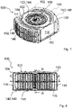
- Figures 7 to 12 show another embodiment of an outdoor air purifier 100 according to the invention.
- Figure 7 shows a perspective view of an outdoor air purifier 100
- Figure 8 shows a front view of the air purifier 100 indicating intersection lines IX-IX and X-X.
- Figure 9 shows a cut view through the outdoor air purifier 100 along intersection line IX-IX of Figure 8
- Figure 10 shows a cut view through the outdoor air purifier 100 along intersection line X-X of Figure 8 .
- Figure 11 shows in an exploded view the arrangement of filter elements and a fan 150 of the outdoor air purifier 100
- Figure 12 shows in a partially exploded view the outdoor air purifier 100.
- the configuration of the air purifier 100 is essentially the same as in the embodiment described in Figures 1 to 6 especially in regards of the housing, the fan 150, the support structure 156. To avoid unnecessary repetitions, reference is made to the description of the aforementioned embodiments for components which are not described in context with the Figures 7 to 12 .
- the grilles 146 covering the two opposing openings 148 of the two flow inlets 142 are curved, e.g. as cylinder segments.
- the housing cover 104 exhibit corresponding similarly curved openings 148.
- the grilles 146 may be attached to the housing 102 by screws or the like attached through holes 111 in the top cover wall 120 of the housing cover part 104.
- the prefilter element 30 provides spacers 31 for positioning the grilles 146 in the opening 148.
- each half of the split filter elements 10, 30 can be inserted or removed from the housing 102 through the opposing openings 148.
- the housing cover part 104 is attached to the mounting base 110 by means of screws, clamps, hooks, weld seam, glue or the like.
- the housing cover part 104 may be attached removably to the mounting base 110 so that the filter elements 10 and/or 30 may be removed in a vertical direction from the housing 102.
- the grilles are attached to the mounting base 110, e.g., by means of screws, clamps, hooks, weld seam, glue or the like.
- the housing cover part 10 may be attached to the mounting base 110 via a hinge so that the housing 102 can be opened by tilting the cover housing part 104.
- Figures 13 to 19 show another embodiment of an outdoor air purifier 100 according to the invention.
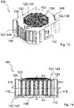
- Figure 13 shows a perspective view of an outdoor air purifier 100
- Figure 14 shows a front view of the air purifier 100 indicating intersection lines XV-XV and XVI-XVI.
- Figure 15 shows a cut view through the outdoor air purifier 100 along intersection line XV-XV of Figure 13
- Figure 16 shows a cut view through the outdoor air purifier 100 along intersection line XVI-XVI of Figure 13 .
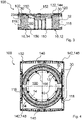
- Figure 17 shows a top view of a detail of a filter element 10 of Figure 13 featuring filter segments 15, 17, 19, 21, 23, 25, 27, 29 connected by a side band 60
- Figure 18 shows a side view of a detail of two filter segments 27, 29 connected by the side band 60 featuring a through hole 62 and a housing element 114
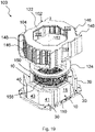
- Figure 19 shows in a partially exploded view the outdoor air purifier 100.
- the outdoor air purifier 100 comprises a housing 102 mounted to a mounting base 110.
- the mounting base 110 includes at least one mounting element that is adapted for the mounting of the outdoor air purifier 100 to a vehicle in particular a roof or roof rail or the like.
- the housing 102 comprises at least one housing part 104 and has a flow inlet 142 for outdoor air to be purified on each of two opposing sides of the housing 102 and a flow outlet 144 for cleaned air in a housing cover part 104.
- the flow inlet 142 is arranged between two side walls 116, 118 of a housing cover part 104.
- the housing cover part 104 includes the side walls 116, 118 which connect the housing cover part 104 to the mounting base 110.
- the housing cover part 104 comprises or consists of a plastic material, especially an injection-moldable plastic material.
- the housing cover part 104 includes a top cover wall 120 extending axially displaced from the mounting base 110 and is arranged, in this embodiment perpendicular, to a rotational axis 152 of a fan 150.
- the top cover wall 120 includes an opening 122 that acts as the flow outlet 144. In this embodiment a diameter of the opening 122 corresponds to a diameter of the fan 150.
- the housing 102 has a curved grille 146 extending over each flow inlet 142 and being integrally formed with the housing cover part 104.
- the flow inlet 142 is provided in the openings 148 of the housing 102 each covered by the grille 146.
- the cross sections of the filter elements 10, 30, mounting base 110 and the housing 102 are essentially polygonal, e.g. octagonal.
- the filter element 10 as main filter element surrounds the inner clean air space 160 of the housing 102 circumferentially and extends essentially parallel to the rotational axis 152 of the fan 150.
- a prefilter element 30 is arranged radially outside, i.e. upstream, of the filter element 10.
- the filter elements 10, 30 may be connected by a side band (not shown).
- the prefilter element 30 may be a separate component or may be attached to the main filter element 10.
- the filter element 10 has an octagonal cross section and is composed of a multitude of filter segments 15, 17, 19, 21, 23, 25, 27, 29. At least two of the of filter segments 15, 17, 19, 21, 23, 25, 27, 29 are connected by means of a side band 60 which is attached at on side of the filter element 10. This may be attached to the top or the bottom of the filter element 10 or both.
- the side band 60 extends essentially parallel to the mounting base 110.
- the multitude of filter segments 15, 17, 19, 21, 23, 25, 27, 29 are connected to each other at the radially inner edges and have an open space between them at the outside. In other embodiments it is possible that only two individually neighboring filter segments 15, 17, 19, 21, 23, 25, 27, 29 are connected by side bands 60.
- a ring 124 is arranged between the housing cover part 104 and the filter element 10 which contacts the upper part of the filter element 10 when the housing cover part is closed.
- the prefilter element 30 is composed of a multitude of filter segments 35, 37, 38, 39, and 41, 43, 45.
- the prefilter element 30 is split in two halves with an equal number of segments 35, 37, 38, 39, and 41, 43, 45 in each half.
- the main filter element 10 in total covers an angular portion of at least 270°, preferably at least 330°, of the circumference of the inner clean air space 160 and is arranged essentially coaxial to the rotational axis 152 of the fan 150.
- Figure 18 illustrates schematically two abutting filter segments 27, 29 attached to the side band 60.
- a connecting region 66 between two neighboring filter segments 27, 29 at least one through-hole 62 is provided, in particular a cut or a slot, through which a housing element 114 protrudes.
- the housing structure 114 may be attached to the mounting base 110 or attached to the housing cover part 104 (not shown).
- the housing structure 114 is provided for positioning the multitude of filter element segments 15, 17, 19, 21; 23, 25, 27, 29.
- the filter segments 35, 37, 39, and 41, 43, 45 of the prefilter element 30 may be connected by a side band 60 (not shown) and positioned via housing structures 114 (not shown).
- the housing structure 114 may be configured as struts or blades, which are configured to protrude through the side band 60.
- the housing structures 114 protruding in the through holes 62 of the side band 60 assure the correct mounting of the octagonally arranged main filter element 10 and assure the correct flow direction in a poka-yoke manner.
- Slicing the filter elements 10, 30 allows the filter elements 10, 30 to be packaged and transported as flat prisms, thus minimizing package volume and allowing stacking of the filter elements 10, 30.
- the fan 150 with its standing rotational axis 152 is arranged within the housing 102, wherein the at least one flow inlet 142 is arranged radially with regards to the rotational axis 152 of the fan 150.
- the at least one outlet 144 is arranged axially with regards to the rotational axis 152 of the fan 150.
- the fan 150 is displaced axially from the mounting base 110 of the housing 102 and is in fluid connection with the inner clean air space 160.
- the fan 150 is held by a support structure 156 attached to the mounting base 110.
- the support structure 156 includes at least the one strut 157 which extends perpendicular with regards to a plane of the mounting base 110.
- the support structure 156 is embodied as a support cage having a multitude of struts 157 angularly distributed around the circumference.
- the support structure 156 is arranged within an inner clean air space 160 and delimits the inner clean air space 160 radially.
- the fan 150 is attached to an upper ring element 158 of the support structure 156 which is supported by the struts 157.
- a grid-like cover 151 of the fan 150 may rest on the upper ring 158 ( Figure 19 ).
- the struts 157 are resting on a lower ring segment 159 of the support structure 156 which is attached to the mounting base 110.
- the support structure 156 may be composed of cylinder segments with two strut segments at each side connected at one end with regards to the rotational axis 152 of the fan 150 by an upper circular segment and at the opposing end with regards to the fan rotational axis 152 by a lower circular segment.
- two abutting strut segment constitute one of the struts 157.
- the support structure 156 acts as a radial support for the at least one filter element 10, 30.
- the filter elements 10, 30 are curved with a curving radius corresponding to a radius of the support structure 156.
- a typical value of the electric power per flow rate for the air purifier 100 is not more than 100 W per 1000 m 3 /h.
- the height of the housing 102 is less 400 mm, preferred less than 350 mm, most preferred less than 300 mm.
- a ratio of height vs. fan diameter is less than 1, preferred less than 0.8, most preferred less than 0.7.
- the filter efficiency is between 50 - 95% ePM2.5 (ISO 16890), preferably between 60-90%.
- the filter elements 10, 30 can be removed from the housing 102 by removing the housing cover part 104 and remove the filter elements 10, 30 in vertical direction.
- the housing cover part 10 may be attached to the mounting base 110 via a hinge so that the housing 102 can be opened by tilting the cover housing part 104.
Landscapes
- Chemical & Material Sciences (AREA)
- Chemical Kinetics & Catalysis (AREA)
- Physics & Mathematics (AREA)
- Geometry (AREA)
- Filtering Of Dispersed Particles In Gases (AREA)
Abstract
Description
- The invention relates to an outdoor air purifier comprising at least one filter element, a filter element for such an air purifier and use of a filter element.
- Particle filter systems such as fine dust filter systems known in the art use direct flow alignments with axial fans in vertical position and filter elements positioned in upstream position from said fan. The height of these systems is typically determined by the diameter of the fan.
-
JP5679796 B2 - It is an object of the invention to provide an outdoor air purifier which allows for a reduced pressure drop.
- Another object of the invention is to provide a filter element for such an outdoor air purifier.
- Another object of the invention is to provide a use of a filter element in an air purifier.
- The first object is achieved by an outdoor air purifier, comprising a housing comprising at least one housing part, wherein the housing has at least one flow inlet for outdoor air to be purified and at least one flow outlet for cleaned air, a fan with a standing rotational axis arranged within the housing, wherein the at least one flow inlet is arranged radially with regards to the rotational axis of the fan, wherein the at least one outlet is arranged axially with regards to the rotational axis of the fan, at least one filter element that at least partially surrounds, in particular circumferentially, an inner clean air space of the housing, wherein the fan is displaced axially from a mounting base of the housing and is in fluid connection with the inner clean air space, wherein the at least one filter element extends essentially parallel to the rotational axis of the fan.
- Another object is achieved by a filter element for an outdoor air purifier, the filter element being configured for connecting to at least one filter element through at least one side band extending essentially parallel to a mounting base, wherein the side band has at least one through-hole, in particular a cut or a slot, in a connecting region between two neighboring filter elements.
- Another object is achieved by use of a filter element in a vehicle mountable outdoor air purifier, the filter element being configured for connecting to at least one filter element through at least one side band extending essentially parallel to a mounting base, wherein the side band has at least one through-hole, in particular a cut or a slot, in a connecting region between two neighboring filter elements, wherein the side band is configured for a housing structure, preferably a strut or a blade, protruding through the through-hole in the side band, in particular wherein the side band is configured for a housing structure, preferably a strut or a blade, protruding through the through-hole in the side band.
- Favorable embodiments and advantages of the invention are apparent from the further claims, the description and the drawings.
- In a first aspect of the invention an outdoor air purifier is proposed, comprising a housing, the housing comprising at least one housing part, wherein the housing has at least one flow inlet for outdoor air to be purified and at least one flow outlet for cleaned air, a fan with a standing rotational axis arranged within the housing, wherein the at least one flow inlet is arranged radially with regards to the rotational axis of the fan, wherein the at least one outlet is arranged axially with regards to the rotational axis of the fan, at least one filter element that at least partially surrounds, in particular circumferentially, an inner clean air space of the housing, wherein the fan is displaced axially from a mounting base of the housing and is in fluid connection with the inner clean air space, wherein the at least one filter element extends essentially parallel to the rotational axis of the fan.
- The air purifier has a low height and a low power consumption as well as a low pressure drop between flow inlet and flow outlet. Fans facing upwards or downwards imply the redirection of the air by up to 90°. This allows for using much larger diameter fans than in vehicle mountable outdoor air purifiers following a purely axial (with regards to a length axis of the vehicle) flow concept. This allows for simple servicing options when filter elements have to be exchanged. In addition, high versatility in terms of element shapes, filter classes and two stage options such as main filter element and prefilter element are possible.
- The low power consumption allows to aggregate higher flow rates, e.g., on bus roofs, and lowers the bar for application on smaller vehicles with smaller batteries and weaker alternators, such as forklifts, tricycles, production machinery, airport carriers and the like.
- For small vehicles, the air flow direction may also be advantageous, as the driver will not be exposed to a strong draft which may be created by the air purifier.
- A fan may be used that is larger than the system height. Advantageously the fan may be tilted, preferably by 90°, from the vertical, facing upwards or downwards. Due to the limited system height, it is further advantageous to arrange the filter elements around the fan to increase the flow cross-section, i.e. the filter cross-section, which correlates with lower achievable filter element and filter system pressure loss. Pressure loss in the air purifier is mainly governed by the pressure loss of the filter element. Considering a given fan and target flow rate, a lower pressure drop allows to reduce the fan rotational speed, which leads to reduced power consumption and a reduction of the noise emissions. A concentric arrangement is furthermore advantageous because it leads to a circular clean air space that allows for a homogeneous air flow towards the fan. The free space can further be used to implement an (optional) flow grid or other air guiding structures optimizing the flow pattern towards the fan and leading to an improvement of pressure drop and acoustics.
- Advantageously, it is possible to stay within the height range of other typical vehicle roof aggregates (e.g. A/C systems), which rarely exceed 300 mm.
- According to a favorable embodiment of the outdoor air purifier the at least one filter element in total may cover an angular portion of at least 270°, preferably at least 330°, of the circumference of the inner clean air space. This allows for a large filter area inside the housing.
- According to a favorable embodiment of the outdoor air purifier the filter element may be arranged essentially coaxial to the rotational axis of the fan. A concentric arrangement advantageously leads to a circular clean air space that allows for a homogeneous air flow towards the fan.
- According to a favorable embodiment the outdoor air purifier may comprise a multitude of filter element segments of the at least one filter element, neighboring each other circumferentially, wherein the multitude of filter segments may be arranged in a polygonal or circular shape around the rotational axis of the fan.
- As main filter element round elements or alternatively n-edged arrangements of filter segments, in particular concentric arrangements, may be used, such as hexagonal, octagonal arrangements or the like. In a preferred embodiment, the main filter element may also be concentric with the fan. The air purifier may feature two flow inlets from opposite directions of the housing, and prefilter elements arranged between these inlets and the main elements for pre-separating coarse dust, water, biological material as well as for preventing stone chipping. Such a two-inlet arrangement is advantageous in terms of modularity, as a multitude of filter systems can be stacked side by side, e.g. on a bus roof. Other arrangements with different inlet orientations are also feasible, and allow for different modular approaches. For instance one inlet on two neighboring edges could be used in a square array of the air purifier.
- According to a favorable embodiment of the outdoor air purifier at least two filter elements and/or at least two of the multitude of filter segments may be connected by at least one side band extending essentially parallel to the mounting base, wherein the side band has at least one through-hole, in particular a cut or a slot, in a connecting region between two neighboring filter segments or filter elements.
- The side band may connect a prefilter element and a main filter element in radial direction. Additionally or alternatively, the at least one filter element may be divided into filter segments which are connected by the side band.
- Advantageously, the struts protruding in the through-hole of the side band may assure the correct mounting of the filter elements, in particular of n-edged main filter segments for main filter elements as well as prefilter elements and assure the correct flow direction in a simple poka-yoke fashion.
- According to a favorable embodiment of the outdoor air purifier a housing structure may be provided for positioning the multitude of filter element segments. In particular the housing structure may be configured as a strut or blade. In particular the housing structure may be configured to protrude through the side band.
- The housing structure may be arranged at the mounting base or the housing cover part and especially extending parallel to the rotational axis of the fan.
- By providing the housing structure such as struts or blades protruding through the through hole of the side band the correct mounting of the filter elements and/or the filter segments and a the correct flow direction are achieved.
- Slicing the filter elements into filter segments allows the filter elements to be packaged and transported as flat prisms, thus minimizing package volume and allowing stacking the filter elements in a compact manner.
- According to a favorable embodiment of the outdoor air purifier the at least one filter element may be arranged concentrically around a center of the inner clean air space, wherein the center of the inner clean air space is defined by the rotational axis of the fan. This allows for a compact arrangement of filter elements and fan.
- According to a favorable embodiment of the outdoor air purifier the filter element may include at least one filter medium, in particular provided in the form of a pleated filter bellows.
- According to a favorable embodiment of the outdoor air purifier the fan may be held by a support structure attached to the mounting base. Optionally the support structure may include at least the one strut, preferably extending perpendicular with regards to a plane of the mounting base.
- In one preferred embodiment, the support structure is arranged below the fan. The mounting structure is mounted to the baseplate and positioned in the clean air room formed by the at least one main filter element. Advantageously, the housing cover itself may fulfil the functions of creating air tightness between main element forming an air tight clean air room and tightening the support structure of the fan. In this case, the concentric arrangement offers the benefit that only a small region within the air purifier needs to be kept sealed or airtight, i.e. the interface between the filter element and housing cover and the adjacent area, e.g., an inner ring area, between filter element and fan. On the bottom of the at least one filter elements, an interface between element and mounting base is created which can by tightened in a simple fashion. For instance axial sealing with polyurethane (PU) or foam, or even mere labyrinth sealing can be employed which is sufficient for filter efficiencies when sidebands are used. The prefilter does not necessarily require airtight sealing, so that simple labyrinth sealing approaches are sufficient.
- According to a favorable embodiment of the outdoor air purifier the support structure may be embodied as a support cage having a multitude of struts angularly distributed around the circumference. This yields a stable and robust support for the fan.
- According to a favorable embodiment of the outdoor air purifier the support structure may act as a radial support for the at least one filter element. Advantageously, a compact and stable support is provided along the filter element surface.
- According to a favorable embodiment of the outdoor air purifier the at least one filter element is curved with a curving radius corresponding to a radius of the support structure. This improves the support of the filter element.
- According to a favorable embodiment of the outdoor air purifier the housing cover part may include a top cover wall extending axially displaced from the mounting base, preferably at least parallel, and preferably the housing cover part may include at least one side wall connecting the housing cover part to the mounting base.
- Advantageously, a vacuum formed hood may be used to form the housing cover part of the housing. The bottom of the air purifier may be formed by a base plate with multiple holes intended for, e.g., water drainage as well as mounting the air purifier to a position, e.g., by bolting, screwing and the like.
- Further advantageous functions can be integrated into the housing cover part, such as grooves to guide rain water and/or increase the stiffness (mechanics/acoustics), formation of air guiding structures, e.g. diffusor at the inlet and outlet regions.
- Servicing the filter element can be done in two different fashions, leading to different system design. In one embodiment, the housing cover part may be removed completely. In another embodiment the housing cover part may be tilted by using a hinge. This service concept allows a multitude of prefilter and main element shapes and styles, such as round, flat panels, conical, or V-banks with variable bank size and the like, as long as they form an essentially circular clean air space and hence a homogeneous air distribution towards the fan.
- In another embodiment an alternative service option may comprise filter elements that can be serviced through the inlet openings. This is advantageous for passenger car applications, as the roof of passenger cars is difficult to access. This servicing concept requires the main element to be splitable and implies the need to design an interface between the split element halves, such as foam sealing, flat sealing and the like and detachable connectors.'
- According to a favorable embodiment of the outdoor air purifier the electric power consumption per flow rate may be less than 100 W per 1000 m3/h. Such parameters are achievable by the construction of the proposed air purifier.
- According to a favorable embodiment of the outdoor air purifier the height of the outdoor air purifier may be less than 400 mm, preferably less than 350 mm, most preferably less than 300 mm. Such parameters are achievable by the construction of the proposed air purifier.
- According to a favorable embodiment of the outdoor air purifier the ratio of height vs. fan diameter may be less than 1, preferably less than 0.8, most preferably less than 0.7. Such parameters are achievable by the construction of the proposed air purifier.
- According to a favorable embodiment of the outdoor air purifier the filter efficiency may be between 50% and 95%, preferably between 60%-90% (gravimetric filter efficiency for fine dust, expressed as ePM2.5 as per ISO 16890:2016). Such parameters are achievable by the construction of the proposed air purifier.
- Advantageously, the power consumption is so low that the proposed air purifier becomes an option to power the system independently and without connection to an on-board 12V/24V circuits of vehicles by, e.g., batteries, solar panels, contact free magnetic charging and the like, which simplifies homologation and customer acceptance. In particular there is no loss of the range for electric vehicles.
- In an advantageous embodiment the outdoor air purifier has least one contact free electrical energy transfer means, in particular an inductive electrical energy transfer means, arranged at the housing.
- According to a favorable embodiment of the outdoor air purifier the top cover wall may include at least one opening that acts as the flow outlet, wherein preferably a diameter of the opening corresponds to a diameter of the fan.
- In another as well preferred embodiment the top cover wall in the region of the opening has a circumferential wall surrounding the opening that provides in the axial direction an increasing diameter of the opening. The diameter of the opening in particular increases in the direction of an outlet flow. This has the advantage that the circumferential wall forms a diffusor (in other words a "bellmouth shape") on the outlet side of the fan that optimizes the flow.
- According to another aspect of the invention a filter element for an outdoor air purifier is proposed, the filter element comprising a multitude of filter element neighboring each other circumferentially. The multitude of filter segments is adapted to be arranged in a polygonal or circular shape around the rotational axis of the fan of the outdoor air purifier in an installed state. At least two of the multitude of filter element segments are connected through at least one side band adapted to extend essentially parallel to the mounting base of the outdoor air purifier in an installed state. Further, the side band has at least one through-hole, in particular a cut or a slot, in a connecting region between two neighboring filter segments.
- By providing the housing structure such as struts or blades protruding through the through hole of the side band the correct mounting of the filter elements and/or the filter segments and a the correct flow direction are achieved.
- Slicing the filter elements into filter segments allows the filter elements to be packaged and transported as flat prisms, thus minimizing package volume and allowing stacking the filter elements in a compact manner.
- According to a favorable embodiment of the filter element the side band may be configured for a housing structure of the outdoor air purifier, preferably a strut or a blade, protruding through the through-hole in the side band.
- According to another aspect of the invention a use of a filter element in a vehicle mountable outdoor air purifier is proposed, the filter element being configured for connecting to at least one filter element through at least one side band extending essentially parallel to a mounting base, wherein the side band has at least one through-hole, in particular a cut or a slot, in a connecting region between two neighboring filter elements, wherein the side band is configured for a housing structure, preferably a strut or a blade, protruding through the through-hole in the side band, in particular wherein the side band is configured for a housing structure, preferably a strut or a blade, protruding through the through-hole in the side band.
- Advantageously, the outdoor air purifier allows for substantial reductions of the fine dust emission footprint of a vehicle by means of the filter element. Very high flow rates are required, in the order of 10.000 m3/h for a bus and full compensation of fine dust emissions (depending on the environmental pollution concentration level). With the limited power available on the vehicle, power efficiency is extremely important for systems targeting full compensation. This implies the need for filter systems with extremely low pressure drop and for the use of large fans. Both can be improved by increasing the filter system's dimensions. However, filter system size and especially system height are limited for roof-carried systems.
- High flow rate per power ratios are particularly relevant for fine dust filters on battery electric vehicles, as the power consumption of the air purifier may directly affect the range.
- The present invention together with the above-mentioned and other objects and advantages may best be understood from the following detailed description of the embodiments, but not restricted to the embodiments, wherein is shown in:
- Figure 1
- a perspective view of an outdoor air purifier according to an embodiment of the invention;
- Figure 2
- a front view of the air purifier shown in
Figure 1 indicating intersection lines III-III and IV-IV; - Figure 3
- a cut view through the outdoor air purifier of
Figure 1 along intersection line III-III ofFigure 2 ; - Figure 4
- a cut view through the outdoor air purifier of
Figure 1 along intersection line IV-IV ofFigure 2 ; - Figure 5
- in an exploded view the arrangement of the filter element and the fan of the outdoor air purifier of
Figure 1 ; - Figure 6
- in an exploded view the outdoor air purifier of
Figure 1 ; - Figure 7
- a perspective view of an outdoor air purifier according to another embodiment of the invention;
- Figure 8
- a front view of the air purifier shown in
Figure 7 indicating intersection lines IX-IX and X-X; - Figure 9
- a cut view through the outdoor air purifier of
Figure 7 along intersection line IX-IX ofFigure 8 ; - Figure 10
- a cut view through the outdoor air purifier of
Figure 7 along intersection line X-X ofFigure 8 ; - Figure 11
- in an exploded view the arrangement of the filter element and the fan of the outdoor air purifier of
Figure 7 ; - Figure 12
- in a partially exploded view the outdoor air purifier of
Figure 7 ; - Figure 13
- a perspective view of an outdoor air purifier according to another embodiment of the invention;
- Figure 14
- a front view of the air purifier shown in
Figure 13 indicating intersection lines XV-XV and XVI-XVI; - Figure 15
- a cut view through the outdoor air purifier of
Figure 14 along intersection line XV-XV ofFigure 13 ; - Figure 16
- a cut view through the outdoor air purifier of
Figure 14 along intersection line XVI-XVI ofFigure 13 ; - Figure 17
- a top view of a detail of the filter element of
Figure 13 featuring filter segments connected by a side band; - Figure 18
- a side view of a detail of two filter segments connected by a side band of
Figure 17 ; - Figure 19
- in a partially exploded view the outdoor air purifier of
Figure13 . - In the drawings, like elements are referred to with equal reference numerals. The drawings are merely schematic representations, not intended to portray specific parameters of the invention. Moreover, the drawings are intended to depict only typical embodiments of the invention and therefore should not be considered as limiting the scope of the invention.
-
Figures 1 to 6 illustrate a first embodiment of anoutdoor air purifier 100 according to the invention.Figure 1 shows a perspective view of anoutdoor air purifier 100 andFigure 2 shows a front view of theair purifier 100 indicating intersection lines III-III and IV-IV.Figure 3 shows a cut view through theoutdoor air purifier 100 along intersection line III-III ofFigure 2 andFigure 4 shows a cut view through theoutdoor air purifier 100 along intersection line IV-IV ofFigure 2 .Figure 5 shows in an exploded view the arrangement offilter elements fan 150 of theoutdoor air purifier 100 andFigure 6 shows in an exploded view theoutdoor air purifier 100. - The
outdoor air purifier 100 comprises ahousing 102 mounted to a mountingbase 110. The mountingbase 110 includes at least one mounting element that is adapted for the mounting of theoutdoor air purifier 100 to a vehicle in particular a roof or roof rail or the like. - The
housing 102 comprises at least onehousing part 104 and has a flow inlet 142 for outdoor air to be purified on each of two opposing sides of thehousing 102 and a flow outlet 144 for cleaned air in ahousing cover part 104. The flow inlet 142 is arranged between twoside walls housing cover part 104. Thehousing cover part 104 includes theside walls housing cover part 104 to the mountingbase 110. Thehousing cover part 104 comprises or consists of a plastic material, especially an injection-moldable plastic material. Thehousing cover part 104 may be preferably produced by vacuum forming. - The
housing cover part 104 includes atop cover wall 120 extending axially displaced from the mountingbase 110 and is arranged, in this embodiment, perpendicular, to arotational axis 152 of afan 150. Thetop cover wall 120 includes anopening 122 that acts as the flow outlet 144. In this embodiment a diameter of theopening 122 corresponds to a diameter of thefan 150. - The
housing 102 has aplanar grille 146 extending over each flow inlet 142. The flow inlet 142 is provided in anopening 148 of thehousing 102. Thegrille 146 may extend over thecomplete opening 148. - The
fan 150 with its standingrotational axis 152 is arranged within thehousing 102, wherein the at least one flow inlet 142 is arranged radially with regards to therotational axis 152 of thefan 150. The at least one outlet 144 is arranged axially with regards to therotational axis 152 of thefan 150. - The
fan 150 is displaced axially from the mountingbase 110 of thehousing 102 and is in fluid connection with the innerclean air space 160. Thefan 150 is held by asupport structure 156 attached to the mountingbase 110. Thesupport structure 156 includes at least the onestrut 157 which extends perpendicular with regards to a plane of the mountingbase 110. - The
support structure 156 is embodied as a support cage having a multitude ofstruts 157 angularly distributed around the circumference. Thesupport structure 156 is arranged within an innerclean air space 160 and delimits the innerclean air space 160 radially. Thefan 150 is attached to anupper ring element 158 of thesupport structure 156 which is supported by thestruts 157. For instance, a grid-like cover 151 of thefan 150 may rest on the upper ring 158 (Figure 5 ). Thestruts 157 are resting on alower ring segment 159 of thesupport structure 156 which is attached to the mountingbase 110. In particular, thesupport structure 156 may be composed of cylinder segments with two strut segments at each side connected at one end with regards to therotational axis 152 of thefan 150 by an upper circular segment and at the opposing end with regards to the fanrotational axis 152 by a lower circular segment. In an assembled state of the cylinder segments, two abutting strut segment constitute one of thestruts 157. - The
support structure 156 acts as a radial support for the at least onefilter element filter elements support structure 156. - The
filter element 10 as main filter element surrounds the innerclean air space 160 of thehousing 102 circumferentially and extends essentially parallel to therotational axis 152 of thefan 150. Aprefilter element 30 is arranged radially outside, i.e. upstream, of thefilter element 10. The pre- 30 andmain filter elements 10 are connected by a curved frame in that they are separably inserted. Theprefilter element 30 and themain filter element 10 can be separately removed from the frame, as this advantageously allows for different service intervals (in general the prefilter element is loaded timely before the main filter element). In other embodiments it is also possible that theprefilter element 30 and themain filter element 10 are inseparably connected to the frame An axial end face of the frame can have a seal extending in the circumferential direction. - The
filter elements clean air space 160 and are arranged essentially coaxial to therotational axis 152 of thefan 150. - The
filter elements element parts element parts - The upper and lower sides of the
filter element parts housing cover part 104 and the mountingbase 110, respectively (Figure 3 ) and the side edges of thefilter element parts abut side walls housing 102 in a tight manner and seal the inner clean air space 160 (Figure 4 ). - A typical value of the electric power per flow rate for the
air purifier 100 is not more than 100 W per 1000 m3/h. The height of thehousing 102 is less than 400 mm, preferred less than 350 mm, most preferred less than 300 mm. A ratio of height vs. fan diameter is less than 1, preferred less than 0.8, most preferred less than 0.7. The filter efficiency is between 50 - 95% ePM2.5 (ISO 16890), preferably between 60-90%. However other filtration efficiencies can be achieved by simply exchanging the filter elements. - As can be seen in particular in
Figures 5 and 6 , thefilter elements housing 102 by removing thegrilles 146 fromopenings 148 and removing theelement parts openings 148. - Alternatively, however, it may be possible to remove the
housing cover part 104 and remove thefilter elements grilles 146 are preferably attached to the mountingbase 110. In this case, the grilles are attached to the mountingbase 110, e.g., by means of screws, clamps, hooks, weld seam, glue or the like. - In an alternative embodiment not shown, the
housing cover part 10 may be attached to the mountingbase 110 via a hinge so that thehousing 102 can be opened by tilting thecover housing part 104. -
Figures 7 to 12 show another embodiment of anoutdoor air purifier 100 according to the invention.Figure 7 shows a perspective view of anoutdoor air purifier 100 andFigure 8 shows a front view of theair purifier 100 indicating intersection lines IX-IX and X-X.Figure 9 shows a cut view through theoutdoor air purifier 100 along intersection line IX-IX ofFigure 8 andFigure 10 shows a cut view through theoutdoor air purifier 100 along intersection line X-X ofFigure 8 .Figure 11 shows in an exploded view the arrangement of filter elements and afan 150 of theoutdoor air purifier 100, andFigure 12 shows in a partially exploded view theoutdoor air purifier 100. - The configuration of the
air purifier 100 is essentially the same as in the embodiment described inFigures 1 to 6 especially in regards of the housing, thefan 150, thesupport structure 156. To avoid unnecessary repetitions, reference is made to the description of the aforementioned embodiments for components which are not described in context with theFigures 7 to 12 . - Other than in the previous embodiments, the
grilles 146 covering the two opposingopenings 148 of the two flow inlets 142 are curved, e.g. as cylinder segments. Thehousing cover 104 exhibit corresponding similarlycurved openings 148. - As can be seen in
Figure 11 , thegrilles 146 may be attached to thehousing 102 by screws or the like attached throughholes 111 in thetop cover wall 120 of thehousing cover part 104. - The
prefilter element 30 providesspacers 31 for positioning thegrilles 146 in theopening 148. In this case, each half of thesplit filter elements housing 102 through the opposingopenings 148. In this case, thehousing cover part 104 is attached to the mountingbase 110 by means of screws, clamps, hooks, weld seam, glue or the like. - Alternatively, as shown in
Figure 12 , thehousing cover part 104 may be attached removably to the mountingbase 110 so that thefilter elements 10 and/or 30 may be removed in a vertical direction from thehousing 102. In this case, the grilles are attached to the mountingbase 110, e.g., by means of screws, clamps, hooks, weld seam, glue or the like. - In an embodiment not shown, the
housing cover part 10 may be attached to the mountingbase 110 via a hinge so that thehousing 102 can be opened by tilting thecover housing part 104. -
Figures 13 to 19 show another embodiment of anoutdoor air purifier 100 according to the invention.Figure 13 shows a perspective view of anoutdoor air purifier 100, andFigure 14 shows a front view of theair purifier 100 indicating intersection lines XV-XV and XVI-XVI.Figure 15 shows a cut view through theoutdoor air purifier 100 along intersection line XV-XV ofFigure 13 , andFigure 16 shows a cut view through theoutdoor air purifier 100 along intersection line XVI-XVI ofFigure 13 .Figure 17 shows a top view of a detail of afilter element 10 ofFigure 13 featuringfilter segments side band 60, andFigure 18 shows a side view of a detail of twofilter segments side band 60 featuring a throughhole 62 and ahousing element 114.Figure 19 shows in a partially exploded view theoutdoor air purifier 100. - The
outdoor air purifier 100 comprises ahousing 102 mounted to a mountingbase 110. The mountingbase 110 includes at least one mounting element that is adapted for the mounting of theoutdoor air purifier 100 to a vehicle in particular a roof or roof rail or the like. - The
housing 102 comprises at least onehousing part 104 and has a flow inlet 142 for outdoor air to be purified on each of two opposing sides of thehousing 102 and a flow outlet 144 for cleaned air in ahousing cover part 104. The flow inlet 142 is arranged between twoside walls housing cover part 104. Thehousing cover part 104 includes theside walls housing cover part 104 to the mountingbase 110. Thehousing cover part 104 comprises or consists of a plastic material, especially an injection-moldable plastic material. - The
housing cover part 104 includes atop cover wall 120 extending axially displaced from the mountingbase 110 and is arranged, in this embodiment perpendicular, to arotational axis 152 of afan 150. Thetop cover wall 120 includes anopening 122 that acts as the flow outlet 144. In this embodiment a diameter of theopening 122 corresponds to a diameter of thefan 150. - The
housing 102 has acurved grille 146 extending over each flow inlet 142 and being integrally formed with thehousing cover part 104. The flow inlet 142 is provided in theopenings 148 of thehousing 102 each covered by thegrille 146. - As can be seen in
Figures 13 ,16 ,17 and19 , the cross sections of thefilter elements base 110 and thehousing 102 are essentially polygonal, e.g. octagonal. - The
filter element 10 as main filter element surrounds the innerclean air space 160 of thehousing 102 circumferentially and extends essentially parallel to therotational axis 152 of thefan 150. Aprefilter element 30 is arranged radially outside, i.e. upstream, of thefilter element 10. Thefilter elements prefilter element 30 may be a separate component or may be attached to themain filter element 10. - As can be seen in
Figure 17 thefilter element 10 has an octagonal cross section and is composed of a multitude offilter segments filter segments side band 60 which is attached at on side of thefilter element 10. This may be attached to the top or the bottom of thefilter element 10 or both. Theside band 60 extends essentially parallel to the mountingbase 110. The multitude offilter segments filter segments side bands 60. - As can be seen in
Figures 15 and19 aring 124 is arranged between thehousing cover part 104 and thefilter element 10 which contacts the upper part of thefilter element 10 when the housing cover part is closed. - Likewise, the
prefilter element 30 is composed of a multitude offilter segments prefilter element 30 is split in two halves with an equal number ofsegments - The
main filter element 10 in total covers an angular portion of at least 270°, preferably at least 330°, of the circumference of the innerclean air space 160 and is arranged essentially coaxial to therotational axis 152 of thefan 150. -
Figure 18 illustrates schematically twoabutting filter segments side band 60. In a connectingregion 66 between twoneighboring filter segments hole 62 is provided, in particular a cut or a slot, through which ahousing element 114 protrudes. Thehousing structure 114 may be attached to the mountingbase 110 or attached to the housing cover part 104 (not shown). - The
housing structure 114 is provided for positioning the multitude offilter element segments - Likewise, the
filter segments prefilter element 30 may be connected by a side band 60 (not shown) and positioned via housing structures 114 (not shown). - The
housing structure 114 may be configured as struts or blades, which are configured to protrude through theside band 60. - The
housing structures 114 protruding in the throughholes 62 of theside band 60 assure the correct mounting of the octagonally arrangedmain filter element 10 and assure the correct flow direction in a poka-yoke manner. - Slicing the
filter elements filter elements filter elements - The
fan 150 with its standingrotational axis 152 is arranged within thehousing 102, wherein the at least one flow inlet 142 is arranged radially with regards to therotational axis 152 of thefan 150. The at least one outlet 144 is arranged axially with regards to therotational axis 152 of thefan 150. - The
fan 150 is displaced axially from the mountingbase 110 of thehousing 102 and is in fluid connection with the innerclean air space 160. Thefan 150 is held by asupport structure 156 attached to the mountingbase 110. Thesupport structure 156 includes at least the onestrut 157 which extends perpendicular with regards to a plane of the mountingbase 110. - The
support structure 156 is embodied as a support cage having a multitude ofstruts 157 angularly distributed around the circumference. Thesupport structure 156 is arranged within an innerclean air space 160 and delimits the innerclean air space 160 radially. Thefan 150 is attached to anupper ring element 158 of thesupport structure 156 which is supported by thestruts 157. For instance, a grid-like cover 151 of thefan 150 may rest on the upper ring 158 (Figure 19 ). Thestruts 157 are resting on alower ring segment 159 of thesupport structure 156 which is attached to the mountingbase 110. In particular, thesupport structure 156 may be composed of cylinder segments with two strut segments at each side connected at one end with regards to therotational axis 152 of thefan 150 by an upper circular segment and at the opposing end with regards to the fanrotational axis 152 by a lower circular segment. In an assembled state of the cylinder segments, two abutting strut segment constitute one of thestruts 157. - The
support structure 156 acts as a radial support for the at least onefilter element filter elements support structure 156. - A typical value of the electric power per flow rate for the
air purifier 100 is not more than 100 W per 1000 m3/h. The height of thehousing 102 is less 400 mm, preferred less than 350 mm, most preferred less than 300 mm. A ratio of height vs. fan diameter is less than 1, preferred less than 0.8, most preferred less than 0.7. The filter efficiency is between 50 - 95% ePM2.5 (ISO 16890), preferably between 60-90%. - As can be seen in particular in
Figure 19 , thefilter elements housing 102 by removing thehousing cover part 104 and remove thefilter elements - In an alternative embodiment not shown, the
housing cover part 10 may be attached to the mountingbase 110 via a hinge so that thehousing 102 can be opened by tilting thecover housing part 104. -
- 10
- filter element
- 12
- element part
- 14
- element part
- 15
- segment
- 17
- segment
- 19
- segment
- 21
- segment
- 23
- segment
- 25
- segment
- 27
- segment
- 29
- segment
- 30
- filter element
- 31
- spacer
- 32
- element part
- 34
- element part
- 35
- segment
- 37
- segment
- 39
- segment
- 41
- segment
- 43
- segment
- 45
- segment
- 60
- side band
- 62
- through-hole
- 66
- connecting region
- 100
- outdoor air purifier
- 102
- housing
- 104
- housing cover part
- 110
- mounting base
- 112
- mounting element
- 114
- housing structure
- 116
- side wall
- 118
- side wall
- 120
- top cover wall
- 121
- holed
- 122
- opening
- 124
- ring
- 142
- flow inlet
- 144
- flow outlet
- 146
- grille
- 148
- opening
- 150
- fan
- 151
- grid-like cover
- 152
- rotational axis
- 156
- support structure
- 157
- strut
- 158
- ring
- 159
- ring
- 160
- clean air space
Claims (19)
- An outdoor air purifier (100), comprising
a housing (102) comprising at least one housing part (104), wherein the housing (102) has at least one flow inlet (142) for outdoor air to be purified and at least one flow outlet (144) for cleaned air,
a fan (150) with a standing rotational axis (152) arranged within the housing (102), wherein the at least one flow inlet (142) is arranged radially with regards to the rotational axis (152) of the fan (150), wherein the at least one outlet (144) is arranged axially with regards to the rotational axis (152) of the fan (150),
at least one filter element (10, 30) that at least partially surrounds, in particular circumferentially, an inner clean air space (160) of the housing (102),
wherein the fan (150) is displaced axially from a mounting base (110) of the housing (102) and is in fluid connection with the inner clean air space (160),
wherein the at least one filter element (10, 30) extends essentially parallel to the rotational axis (152) of the fan (150). - The outdoor air purifier according to claim 1, wherein the at least one filter element (10, 30) in total covers an angular portion of at least 270°, preferably at least 330°, of the circumference of the inner clean air space (160).
- The outdoor air purifier according to claim 1 or 2, wherein the filter element (10, 30) is arranged essentially coaxial to the rotational axis (152) of the fan (150).
- The outdoor air purifier according to any one of the preceding claims, comprising a multitude of filter element segments (12, 14, 15, 17, 18, 19, 21; 23, 25, 27, 29; 32, 34, 35, 37, 39, 41, 43, 45) of the at least one filter element (10, 30), neighboring each other circumferentially, wherein the multitude of filter segments (12, 14, 15, 17, 18, 19, 21; 23, 25, 27, 29; 32, 34, 35, 37, 39, 41, 43, 45) is arranged in a polygonal or circular shape around the rotational axis (152) of the fan (150).
- The outdoor air purifier according to claim 4, wherein at least two of the multitude of filter element segments (12, 14, 15, 17, 18, 19, 21; 23, 25, 27, 29; 32, 34, 35, 37, 39, 41, 43, 45) are connected through at least one side band (60) extending essentially parallel to the mounting base (110), wherein the side band (60) has at least one through-hole (62), in particular a cut or a slot, in a connecting region (66) between two neighboring filter segments (12, 14, 15, 17, 18, 19, 21; 23, 25, 27, 29; 32, 34, 35, 37, 39, 41, 43, 45).
- The outdoor air purifier according to claim 4 or 5, wherein a housing structure (114) is provided for positioning the multitude of filter element segments (12, 14, 15, 17, 18, 19, 21; 23, 25, 27, 29; 32, 34, 35, 37, 39, 41, 43, 45), in particular wherein the housing structure (114) is configured as a strut or blade, in particular wherein the housing structure (114) is configured to protrude through the through-hole (62) of the side band (60).
- The outdoor air purifier according to any one of the preceding claims, wherein the at least one filter element (10, 30) is arranged concentrically around a center of the inner clean air space (160), wherein the center of the inner clean air space (160) is defined by the rotational axis (152) of the fan (150).
- The outdoor air purifier according to any one of the preceding claims, wherein the filter element (10, 30) includes at least one filter medium, in particular provided in the form of a pleated filter bellows.
- The outdoor air purifier according to any one of the preceding claims, wherein the fan (150) being held by a support structure (156) attached to the mounting base (110), wherein preferably the support structure (156) includes at least the one strut (157), preferably extending perpendicular with regards to a plane of the mounting base (110).
- The outdoor air purifier according to claim 9, wherein the support structure (156) is embodied as a support cage having a multitude of struts (157) angularly distributed around the circumference.
- The outdoor air purifier according to claim 9 or 10, wherein the support structure (156) on its radially outer side acts as a radial support for the at least one filter element (10, 30).
- The outdoor air purifier according to any one of the claims 9 to 11, wherein the at least one filter element (10, 30) is curved with a curving radius corresponding to a radius of the support structure (156).
- The outdoor air purifier according to any one of the preceding claims, wherein the housing cover part (104) includes a top cover wall (120) extending axially displaced from the mounting base (110), preferably at least parallel, and wherein preferably the housing cover part (104) includes at least one side wall (116, 118) connecting the housing cover part (104) to the mounting base (110).
- The outdoor air purifier according to any one of the preceding claims, wherein the top cover wall (120) includes at least one opening (122) that acts as the flow outlet (144), wherein preferably a diameter of the opening (122) corresponds to a diameter of the fan (150).
- The outdoor air purifier according to claim 14, wherein the top cover wall (120) in the region of the opening (122) has a circumferential wall surrounding the opening (122) which provides in the axial direction an increasing diameter of the opening (122), wherein the diameter of the opening (122) in particular increases in the direction of an outlet flow.
- The outdoor air purifier according to any one of the preceding claims, wherein at least one contact free electrical energy transfer means, in particular an inductive electrical energy transfer means, is arranged at the housing (102).
- A filter element (10, 30) for an outdoor air purifier (100) according to any one of the preceding claims,- comprising a multitude of filter element segments (12, 14, 15, 17, 18, 19, 21; 23, 25, 27, 29; 32, 34, 35, 37, 39, 41, 43, 45) neighboring each other circumferentially,- wherein the multitude of filter segments (12, 14, 15, 17, 18, 19, 21; 23, 25, 27, 29; 32, 34, 35, 37, 39, 41, 43, 45) is adapted to be arranged in a polygonal or circular shape around the rotational axis (152) of the fan (150) of the outdoor air purifier (100) in an installed state,- wherein at least two of the multitude of filter element segments (12, 14, 15, 17, 18, 19, 21; 23, 25, 27, 29; 32, 34, 35, 37, 39, 41, 43, 45) are connected through at least one side band (60) adapted to extend essentially parallel to the mounting base (110) of the outdoor air purifier (100) in an installed state,- and wherein the side band (60) has at least one through-hole (62), in particular a cut or a slot, in a connecting region (66) between two neighboring filter segments (12, 14, 15, 17, 18, 19, 21; 23, 25, 27, 29; 32, 34, 35, 37, 39, 41, 43, 45).
- The filter element according to claim 17, wherein the side band (60) is configured for a housing structure (114) of the outdoor air purifier (100), preferably a strut or a blade, protruding through the through-hole (62) in the side band (60).
- Use of a filter element (10, 30) according to claim 17 or 18 in a vehicle mountable outdoor air purifier (100) according to any one of the claims 1 to 15, for purifying outdoor air.
Priority Applications (4)
| Application Number | Priority Date | Filing Date | Title |
|---|---|---|---|
| EP21181814.1A EP4108309A1 (en) | 2021-06-25 | 2021-06-25 | Outdoor air purifier comprising at least one filter element, filter element for such an air purifier and use of a filter element |
| PCT/EP2022/066747 WO2022268730A1 (en) | 2021-06-25 | 2022-06-20 | Outdoor air purifier comprising at least one filter element and use of a filter element in such an air purifier |
| CN202280044963.4A CN117580630A (en) | 2021-06-25 | 2022-06-20 | Outdoor air purifier comprising at least one filter element and use of the filter element in such air purifier |
| US18/512,688 US12576355B2 (en) | 2021-06-25 | 2023-11-17 | Outdoor air purifier including at least one filter element |
Applications Claiming Priority (1)
| Application Number | Priority Date | Filing Date | Title |
|---|---|---|---|
| EP21181814.1A EP4108309A1 (en) | 2021-06-25 | 2021-06-25 | Outdoor air purifier comprising at least one filter element, filter element for such an air purifier and use of a filter element |
Publications (1)
| Publication Number | Publication Date |
|---|---|
| EP4108309A1 true EP4108309A1 (en) | 2022-12-28 |
Family
ID=76623990
Family Applications (1)
| Application Number | Title | Priority Date | Filing Date |
|---|---|---|---|
| EP21181814.1A Pending EP4108309A1 (en) | 2021-06-25 | 2021-06-25 | Outdoor air purifier comprising at least one filter element, filter element for such an air purifier and use of a filter element |
Country Status (4)
| Country | Link |
|---|---|
| US (1) | US12576355B2 (en) |
| EP (1) | EP4108309A1 (en) |
| CN (1) | CN117580630A (en) |
| WO (1) | WO2022268730A1 (en) |
Families Citing this family (1)
| Publication number | Priority date | Publication date | Assignee | Title |
|---|---|---|---|---|
| US20240042364A1 (en) * | 2022-08-02 | 2024-02-08 | Bissell Inc. | Air purifier with rotatable filter |
Citations (9)
| Publication number | Priority date | Publication date | Assignee | Title |
|---|---|---|---|---|
| JPH07112108A (en) * | 1993-10-19 | 1995-05-02 | Japan Vilene Co Ltd | Folding filter |
| US5753000A (en) * | 1993-08-23 | 1998-05-19 | Honeywell Consumer Products, Inc. | Filter air cleaner |
| DE19804927A1 (en) * | 1997-02-10 | 1998-08-13 | Kioritz Corp | Air cleaner element for I.C. engines |
| WO2007040074A1 (en) * | 2005-09-30 | 2007-04-12 | Sharp Kabushiki Kaisha | Air conditioner and filter used therefor |
| EP2705890A1 (en) * | 2012-09-11 | 2014-03-12 | Carl Freudenberg KG | Filter cartridge |
| JP5679796B2 (en) | 2010-12-17 | 2015-03-04 | 三菱電機株式会社 | Vehicle air conditioner using magnetic filter |
| KR20170140578A (en) * | 2016-06-13 | 2017-12-21 | 엘지전자 주식회사 | Air cleaning apparatus |
| EP3457047A1 (en) * | 2017-09-15 | 2019-03-20 | IQAir AG | Personalised air purification device |
| KR102075373B1 (en) * | 2019-02-14 | 2020-02-10 | 주식회사 광해금속 | Air cleaner for outdoor |
Family Cites Families (9)
| Publication number | Priority date | Publication date | Assignee | Title |
|---|---|---|---|---|
| SE465121B (en) | 1990-06-19 | 1991-07-29 | Ante Eklund | AIR FILTERING DEVICE FOR CAR VEHICLES |
| KR100225503B1 (en) | 1996-12-31 | 1999-10-15 | 오상수 | COOLING SYSTEM OF A ROOF TYPE AIR CONDITIONER FOR USE IN A VEHICLE |
| JPH11157379A (en) | 1997-11-27 | 1999-06-15 | Zeon Kasei Co Ltd | Horticulture freight transportation vehicle and air resistance reduction cover device |
| KR100807813B1 (en) | 2007-02-07 | 2008-02-27 | 최대식 | Atmospheric Purifier for Vehicle |
| CN207565285U (en) | 2017-01-10 | 2018-07-03 | 深圳市航盛电子股份有限公司 | A kind of automobile air purifying device |
| CN206633762U (en) | 2017-02-23 | 2017-11-14 | 莫志棠 | A kind of air purifier for being installed on roof of the vehicle |
| DE102018130158A1 (en) | 2018-11-28 | 2020-05-28 | Aurora Konrad G. Schulz Gmbh & Co. Kg | Rooftop air conditioning unit |
| KR20210157686A (en) * | 2020-06-22 | 2021-12-29 | 코웨이 주식회사 | Air filter and air clearner including the same |
| US20220008601A1 (en) * | 2020-07-13 | 2022-01-13 | San-Hsi WANG | Air purifier |
-
2021
- 2021-06-25 EP EP21181814.1A patent/EP4108309A1/en active Pending
-
2022
- 2022-06-20 WO PCT/EP2022/066747 patent/WO2022268730A1/en not_active Ceased
- 2022-06-20 CN CN202280044963.4A patent/CN117580630A/en active Pending
-
2023
- 2023-11-17 US US18/512,688 patent/US12576355B2/en active Active
Patent Citations (9)
| Publication number | Priority date | Publication date | Assignee | Title |
|---|---|---|---|---|
| US5753000A (en) * | 1993-08-23 | 1998-05-19 | Honeywell Consumer Products, Inc. | Filter air cleaner |
| JPH07112108A (en) * | 1993-10-19 | 1995-05-02 | Japan Vilene Co Ltd | Folding filter |
| DE19804927A1 (en) * | 1997-02-10 | 1998-08-13 | Kioritz Corp | Air cleaner element for I.C. engines |
| WO2007040074A1 (en) * | 2005-09-30 | 2007-04-12 | Sharp Kabushiki Kaisha | Air conditioner and filter used therefor |
| JP5679796B2 (en) | 2010-12-17 | 2015-03-04 | 三菱電機株式会社 | Vehicle air conditioner using magnetic filter |
| EP2705890A1 (en) * | 2012-09-11 | 2014-03-12 | Carl Freudenberg KG | Filter cartridge |
| KR20170140578A (en) * | 2016-06-13 | 2017-12-21 | 엘지전자 주식회사 | Air cleaning apparatus |
| EP3457047A1 (en) * | 2017-09-15 | 2019-03-20 | IQAir AG | Personalised air purification device |
| KR102075373B1 (en) * | 2019-02-14 | 2020-02-10 | 주식회사 광해금속 | Air cleaner for outdoor |
Also Published As
| Publication number | Publication date |
|---|---|
| US20240082768A1 (en) | 2024-03-14 |
| CN117580630A (en) | 2024-02-20 |
| WO2022268730A1 (en) | 2022-12-29 |
| US12576355B2 (en) | 2026-03-17 |
Similar Documents
| Publication | Publication Date | Title |
|---|---|---|
| US20110154991A1 (en) | Intake air filter system | |
| US12576355B2 (en) | Outdoor air purifier including at least one filter element | |
| CN102413941A (en) | Modular cyclone precleaner system and method of producing same | |
| US6315525B1 (en) | Multi-purpose clean air fan and fan motor mount assembly | |
| CN102818322A (en) | Humidifying air purifier | |
| TWI866980B (en) | Fan device | |
| CN2936402Y (en) | Oil mist purifier | |
| CN220379899U (en) | Double-shaft motor air purifier | |
| WO2026017147A1 (en) | Outdoor unit of heating, ventilation and air-conditioning apparatus, and heating, ventilation and air-conditioning apparatus | |
| US20230160584A1 (en) | Air conditioner outdoor unit | |
| EP4223385A1 (en) | Outdoor air purifier comprising at least one filter element and use of a filter element | |
| CN220287616U (en) | Heating and ventilation equipment outdoor unit and heating and ventilation equipment | |
| CN201628321U (en) | Vertical air conditioner | |
| CN117239983A (en) | Powertrain and vehicles | |
| CN205216423U (en) | Two air inlet air purifier | |
| CN214112235U (en) | Assembly structure of photocatalyst component and shell | |
| CN220700840U (en) | Outer machine of parking air conditioner and parking air conditioner | |
| JP3045992B2 (en) | Low concentration nitrogen oxide removal equipment | |
| CN219572210U (en) | Novel water-washing air purifier water suction pipe | |
| CN222352498U (en) | Air purifier with air-out assembly | |
| CN222829327U (en) | A filtration processing unit for air cleaner | |
| CN203925817U (en) | The air intake element and the machine that are used for the twin filter assembly of motor | |
| CN215292930U (en) | Pipeline fan that trades | |
| CN224261891U (en) | Air purification treatment device suitable for garden factory | |
| CN212803426U (en) | Multifunctional air pre-filter |
Legal Events
| Date | Code | Title | Description |
|---|---|---|---|
| PUAI | Public reference made under article 153(3) epc to a published international application that has entered the european phase |
Free format text: ORIGINAL CODE: 0009012 |
|
| STAA | Information on the status of an ep patent application or granted ep patent |
Free format text: STATUS: THE APPLICATION HAS BEEN PUBLISHED |
|
| AK | Designated contracting states |
Kind code of ref document: A1 Designated state(s): AL AT BE BG CH CY CZ DE DK EE ES FI FR GB GR HR HU IE IS IT LI LT LU LV MC MK MT NL NO PL PT RO RS SE SI SK SM TR |
|
| STAA | Information on the status of an ep patent application or granted ep patent |
Free format text: STATUS: REQUEST FOR EXAMINATION WAS MADE |
|
| 17P | Request for examination filed |
Effective date: 20230330 |
|
| RBV | Designated contracting states (corrected) |
Designated state(s): AL AT BE BG CH CY CZ DE DK EE ES FI FR GB GR HR HU IE IS IT LI LT LU LV MC MK MT NL NO PL PT RO RS SE SI SK SM TR |
|
| STAA | Information on the status of an ep patent application or granted ep patent |
Free format text: STATUS: EXAMINATION IS IN PROGRESS |
|
| 17Q | First examination report despatched |
Effective date: 20231113 |