EP4108284A1 - Guide wire - Google Patents
Guide wire Download PDFInfo
- Publication number
- EP4108284A1 EP4108284A1 EP20919670.8A EP20919670A EP4108284A1 EP 4108284 A1 EP4108284 A1 EP 4108284A1 EP 20919670 A EP20919670 A EP 20919670A EP 4108284 A1 EP4108284 A1 EP 4108284A1
- Authority
- EP
- European Patent Office
- Prior art keywords
- marker
- core shaft
- guide wire
- coating film
- resin
- Prior art date
- Legal status (The legal status is an assumption and is not a legal conclusion. Google has not performed a legal analysis and makes no representation as to the accuracy of the status listed.)
- Granted
Links
Images




Classifications
-
- A—HUMAN NECESSITIES
- A61—MEDICAL OR VETERINARY SCIENCE; HYGIENE
- A61M—DEVICES FOR INTRODUCING MEDIA INTO, OR ONTO, THE BODY; DEVICES FOR TRANSDUCING BODY MEDIA OR FOR TAKING MEDIA FROM THE BODY; DEVICES FOR PRODUCING OR ENDING SLEEP OR STUPOR
- A61M25/00—Catheters; Hollow probes
- A61M25/01—Introducing, guiding, advancing, emplacing or holding catheters
- A61M25/09—Guide wires
-
- A—HUMAN NECESSITIES
- A61—MEDICAL OR VETERINARY SCIENCE; HYGIENE
- A61B—DIAGNOSIS; SURGERY; IDENTIFICATION
- A61B1/00—Instruments for performing medical examinations of the interior of cavities or tubes of the body by visual or photographical inspection, e.g. endoscopes; Illuminating arrangements therefor
- A61B1/005—Flexible endoscopes
- A61B1/01—Guiding arrangements therefore
-
- A—HUMAN NECESSITIES
- A61—MEDICAL OR VETERINARY SCIENCE; HYGIENE
- A61M—DEVICES FOR INTRODUCING MEDIA INTO, OR ONTO, THE BODY; DEVICES FOR TRANSDUCING BODY MEDIA OR FOR TAKING MEDIA FROM THE BODY; DEVICES FOR PRODUCING OR ENDING SLEEP OR STUPOR
- A61M25/00—Catheters; Hollow probes
- A61M25/01—Introducing, guiding, advancing, emplacing or holding catheters
- A61M25/09—Guide wires
- A61M2025/09058—Basic structures of guide wires
- A61M2025/09083—Basic structures of guide wires having a coil around a core
-
- A—HUMAN NECESSITIES
- A61—MEDICAL OR VETERINARY SCIENCE; HYGIENE
- A61M—DEVICES FOR INTRODUCING MEDIA INTO, OR ONTO, THE BODY; DEVICES FOR TRANSDUCING BODY MEDIA OR FOR TAKING MEDIA FROM THE BODY; DEVICES FOR PRODUCING OR ENDING SLEEP OR STUPOR
- A61M25/00—Catheters; Hollow probes
- A61M25/01—Introducing, guiding, advancing, emplacing or holding catheters
- A61M25/09—Guide wires
- A61M2025/09133—Guide wires having specific material compositions or coatings; Materials with specific mechanical behaviours, e.g. stiffness, strength to transmit torque
-
- A—HUMAN NECESSITIES
- A61—MEDICAL OR VETERINARY SCIENCE; HYGIENE
- A61M—DEVICES FOR INTRODUCING MEDIA INTO, OR ONTO, THE BODY; DEVICES FOR TRANSDUCING BODY MEDIA OR FOR TAKING MEDIA FROM THE BODY; DEVICES FOR PRODUCING OR ENDING SLEEP OR STUPOR
- A61M2205/00—General characteristics of the apparatus
- A61M2205/02—General characteristics of the apparatus characterised by a particular materials
- A61M2205/0238—General characteristics of the apparatus characterised by a particular materials the material being a coating or protective layer
-
- A—HUMAN NECESSITIES
- A61—MEDICAL OR VETERINARY SCIENCE; HYGIENE
- A61M—DEVICES FOR INTRODUCING MEDIA INTO, OR ONTO, THE BODY; DEVICES FOR TRANSDUCING BODY MEDIA OR FOR TAKING MEDIA FROM THE BODY; DEVICES FOR PRODUCING OR ENDING SLEEP OR STUPOR
- A61M2205/00—General characteristics of the apparatus
- A61M2205/58—Means for facilitating use, e.g. by people with impaired vision
- A61M2205/583—Means for facilitating use, e.g. by people with impaired vision by visual feedback
- A61M2205/584—Means for facilitating use, e.g. by people with impaired vision by visual feedback having a color code
Definitions
- the disclosed embodiments relate to a guide wire.
- Patent Literature 1 discloses a guide wire provided with a raised portion forming layer containing a resin and a pigment, the raised portion forming layer functioning as a visual recognition marker on an outer surface of the guide wire.
- Patent Literature 1 JP 5509276
- the guide wire described in Patent Literature 1 has a problem in that an outer diameter of a portion of the guide wire where the marker is provided is larger than an outer diameter of a portion where the marker is not provided, and thus, there is a limit on a size of a catheter that can be used together with the guide wire.
- Another problem is that the marker protrudes radially outward from the resin portion, and thus, when contacting a device used together with the guide wire or an inner wall of a body cavity, the marker peels off.
- Still another problem is that if the outer diameter of the wire main body is reduced to suppress an increase in the outer diameter of the guide wire, the rigidity of the guide wire is reduced.
- An object of the disclosed embodiments is to suppress an increase of an outer diameter of a guide wire due to provision of a marker on the guide wire in a guide wire provided with a marker containing a resin on an outer surface of a core shaft.
- the disclosed embodiments can be realized in various aspects, and may be realized in a mode such as a method of manufacturing a catheter, an endoscope, an image generation device, an inspection device, a treatment system, and a guide wire, for example.
- Fig. 1 is an explanatory diagram illustrating an entire configuration of a guide wire 1 according to a first embodiment.
- Fig. 2 is an explanatory diagram illustrating a cross-sectional configuration of the guide wire 1.
- the left side in Fig. 1 is referred to as “distal end side” of the guide wire 1 and constituent members
- the right side in Fig. 1 is referred to as "proximal end side” of the guide wire 1 and constituent members.
- the distal end side of the guide wire 1 is a side to be inserted into a body (distal side)
- the proximal end side of the guide wire 1 is a side operated by an operator such as a doctor (near side).
- the guide wire 1 is a medical device used when a catheter is inserted into a blood vessel or a digestive organ, and includes a coating film 10, a core shaft 40, a coil body 50, a distal end side joint portion 60, and a proximal end side joint portion 70.
- the core shaft 40 has an elongated shape, and the coating film 10 is formed on the outer surface of the core shaft 40.
- the coating film 10 includes a marker portion 20 and a resin portion 30.
- the coil body 50 is wound around an outer periphery of the distal end portion of the core shaft 40.
- the core shaft 40 is an elongated (tapered) member configured so that an outer diameter decreases from the proximal end side to the distal end side.
- the core shaft 40 may be formed of a material such as a stainless alloy (SUS302, SUS304, SUS316, and the like), a superelastic alloy such as an Ni-Ti alloy, a piano wire, a nickel-chromium base alloy, a cobalt alloy, and tungsten.
- the core shaft 40 may be formed of a well-known material other than the materials mentioned above.
- a length of the core shaft 40 is not particularly limited, but a range of 1000 mm to 5000 mm may be used as an example.
- the outer diameter of the core shaft 40 is also not particularly limited, but a range of 0.1 mm to 1.0 mm may be used as an example.
- the coil body 50 is configured by one or a plurality of coils, and is wound around the core shaft 40 to cover the outer periphery on the distal end side of the core shaft 40.
- the coil body 50 is wound around a part of a small diameter portion and a tapered portion on the distal end side of the core shaft 40.
- the coil configuring the coil body 50 may be a single coil formed by spirally winding one wire having a circular cross section to form a cylindrical shape, or a hollow, twisted wire coil obtained by forming a twisted wire obtained by twisting a plurality of wires into a cylindrical shape.
- the coil body 50 may be configured by combining a single coil and a hollow twisted wire coil.
- the coil body 50 may be formed of, for example, a stainless alloy (SUS302, SUS304, SUS316, and the like), a superelastic alloy such as an Ni-Ti alloy, a piano wire, a nickel-chromium base alloy, a cobalt alloy, a radiolucent alloy such as tungsten, gold, platinum, tungsten, and a radiopaque alloy such as an alloy containing these elements (for example, a platinum-nickel alloy).
- the coil body 50 may be formed of a well-known material other than the materials mentioned above.
- a length of the coil body 50 is not particularly limited, but for example, 10 mm to 100 mm may be used as an example.
- An outer diameter of the coil body 50 is not particularly limited, but may be in a range of 0.1 mm to 1.0 mm, for example, and is configured to be constant from the distal end to the proximal end.
- the coil body 50 may include a loosely wound portion and a tightly wound portion having different coil pitches.
- the distal end of the coil body 50 is joined to the distal end of the core shaft 40 by the distal end side joint portion 60.
- the proximal end of the coil body 50 is joined to the core shaft 40 by the proximal end side joint portion 70.
- the coil body 50 is fixed to the core shaft 40 by the distal end side joint portion 60 and the proximal end side joint portion 70.
- the distal end side joint portion 60 and the proximal end side joint portion 70 are formed of a metal solder such as silver solder, gold solder, zinc, a Sn-Ag alloy, and an Au-Sn alloy, and by such a metal solder, the coil body 50 and the core shaft 40 are adhered and fixed.
- distal end side joint portion 60 and the proximal end side joint portion 70 may be formed of an adhesive such as an epoxy adhesive, and by such an adhesive, the coil body 60 and the core shaft 20 may be adhered and fixed.
- the distal end side joint portion 60 and the proximal end side joint portion 70 may be formed of different materials.
- the coating film 10 is formed on the outer surface of the core shaft 40, and includes the marker portion 20 and the resin portion 30.
- the coating film 10 is arranged on the proximal end side of the core shaft 40 relative to the proximal end side joint portion 70.
- a length of a zone where the marker portion 20 is formed is not particularly limited, but a range of 100 mm to 500 mm may be used as an example.
- the coating film 10 may cover not only the outer surface of the core shaft 40 on the proximal end side relative to the proximal end side joint portion 70, but also the proximal end side joint portion 70, the coil body 50, and the distal end side joint portion 60.
- the marker portion 20 contains a pigment and is formed on the outer surface of the core shaft 40.
- the marker portion 20 forms a part of the outer surface of the coating film 10.
- the marker portion 20 is a linear site formed in a part of the coating film 10, and is configured to be visually distinguishable from the resin portion 30.
- the marker portion 20 is seen as a linear pattern on the guide wire 1, and when the operator observes a change of an orientation and a position of the pattern when operating the guide wire 1, it is possible to confirm push-pull and rotation operations of the guide wire 1.
- the marker portion 20 is formed to have a wavy pattern in a developed view obtained when the outer periphery of the core shaft 40 is expanded. That is, when the pigment dripping toward the core shaft 40 is moved along the stretching direction in a state where the core shaft 40 is reciprocated and rotated by a predetermined angle (for example, 180°) to the left and right with the stretching direction (axis direction) as a rotation axis, it is possible to from such a wavy pattern.
- the marker portion 40 may be spirally formed on the core shaft 40. That is, when the pigment dripping toward the core shaft 40 is moved along the stretching direction in a state where the core shaft 40 is rotated in one direction with the stretching direction (axis direction) as a rotation axis, it is possible to from a spiral pattern.
- the pigment forming the marker portion 20 may be any one of an inorganic pigment and an organic pigment, but it is preferable to use an inorganic pigment in terms of heat resistance.
- an inorganic pigment it is possible to use carbon black, mica, titanium dioxide, titanium yellow, Prussian blue, Milori blue, cobalt blue, ultramarine, viridian, and the like.
- the marker portion 20 may contain a resin, and may contain PAI (polyamide-imide), PTFE (polytetrafluoroethylene), PVDF (polyvinylidene fluoride), PFA (perfluoroalkoxy alkane), FEP (perfluoroethylene propene), ETFE (ethylene tetrafluoroethylene), PE (polyethylene), and PP (polypropylene), for example.
- the marker portion 30 may be formed of a well-known material other than the above examples.
- the marker portion 20 may contain the same type of resin as or a type different from the resin forming the resin portion 30.
- the resin portion 30 contains a resin and is formed on the outer surface of the core shaft 40.
- the resin portion 30 forms a part of the outer surface of the coating film 10.
- the resin portion 30 may be formed of PAI (polyamide-imide), PTFE (polytetrafluoroethylene), PVDF (polyvinylidene fluoride), PFA (perfluoroalkoxy alkane), FEP (perfluoroethylene propene), ETFE (ethylene tetrafluoroethylene), PE (polyethylene), and PP (polypropylene), for example.
- the resin portion 30 may be formed of a well-known material other than the above examples.
- the resin portion 30 may contain a pigment, which may be any one of an inorganic pigment and an organic pigment, but it is preferable to use the inorganic pigment in terms of heat resistance.
- the inorganic pigment it is possible to use carbon black, mica, titanium dioxide, titanium yellow, Prussian blue, Milori blue, cobalt blue, ultramarine, viridian, and the like.
- the resin portion 30 is formed to be different in color from the marker portion 20, it is possible to increase the visibility of the marker portion 20.
- the marker portion 20 and the resin portion 30 are repeatedly represented as a result of the marker portion 20 and the resin portion 30 being alternately and continuously present without gaps along the stretching direction of the guide wire 1.
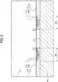
- Fig. 3 is an explanatory diagram obtained when an X portion of Fig. 2 is enlarged.
- the X portion is a portion located on the proximal end side relative to the proximal end side joint portion 70 in Fig. 2 and provided with the coating film 10 on the outer surface of the core shaft 40, and is provided with the marker portion 20.
- the X portion is used as an example to describe a detailed configuration of the marker portion 20 and the resin portion 30.
- a thickness of a portion of the coating film 10 where the marker portion 20 is represented on the outer surface is defined as Hm. It is assumed here that the thickness Hm is a maximum value of a length from the outer surface of the marker portion 20 to the outer surface of the core shaft 40 in the longitudinal section of the core shaft 40.
- the thickness Hm is not particularly limited, but a range of 0.01 mm to 0.1 mm may be used as an example.
- the outer surface of the marker portion 20 is flat, and thus, the thickness Hm remains substantially the same at any point in the stretching direction of the core shaft 40.
- a thickness of a portion of the coating film 10 in which the resin portion 30 is represented on the outer surface, the portion existing between adjacent ones of the marker portions 20, is defined as Hr. It is assumed here that the thickness Hr is a maximum value of a length from the outer surface of the resin portion 30 to the outer surface of the core shaft 40 in the longitudinal section of the core shaft 40.
- the thickness Hr is not particularly limited, but a range of 0.01 mm to 0.1 mm may be used as an example.
- the outer surface of the resin portion 30 is flat, and thus, the thickness Hr remains substantially the same at any point in the stretching direction of the core shaft 40.
- the thickness Hm of the portion of the coating film 10 where the marker portion 20 is represented on the outer surface is substantially the same as the thickness Hr of the portion of the coating film 10 where the resin portion 30 is represented on the outer surface.
- the outer surface of the marker portion 20 and the outer surface of the resin portion 30 are formed to be flat.
- a difference between the thickness Hm and the thickness Hr is equal to or less than 20 pm, and more preferably equal to or less than 10 pm.
- a length of the marker portion 20 in the stretching direction of the core shaft 40 is defined as a cross-sectional width of the marker portion 20.
- the cross-sectional width of the marker portion 20 on the outer surface of the marker portion 20 is defined as an outer cross-sectional width Wm.
- the marker portion 20 is of arc shape, and of convex shape inward in a radial direction of the core shaft 40, and thus, the cross-sectional width of the marker portion 20 gradually decreases inward in the radial direction of the core shaft 40. In other words, the cross-sectional width of the marker portion 20 gradually increases outward in the radial direction of the core shaft 40.
- the marker portion 20 includes a first region 20a including the outer surface of the marker portion 20 and a second region 20b provided around the first region 20a.
- the first region 20a is of arc shape, and is of convex shape toward the inside of the core shaft 40 in the radial direction.
- the second region 20b is of arc shape to cover a surrounding area of the first region, and is of convex shape toward the inside of the core shaft 40 in the radial direction.
- a content of the pigment contained in the second region 20b is smaller than a content of the pigment contained in the first region 20a. If the marker portion 20 is configured by the resin and the pigment, the content of the pigment contained in the second region 20b is larger than the content of the pigment contained in the first region 20a.
- Fig. 4 is an explanatory diagram illustrating a method of manufacturing the guide wire 1. If an average particle size of a pigment 100 contained in the marker portion 20 is smaller than an average particle size of the resin of the resin portion 30, it is possible to manufacture the marker portion 20 represented by a wavy pattern on the resin portion 30 according to the following steps, for example. Firstly, the resin portion 30 is coated on the outer surface of the core shaft 40. Next, in a state where the core shaft 40 is reciprocated and rotated by a predetermined angle (for example, 180°) to the left and right with the stretching direction (axis direction) as a rotation axis, the pigment 100 dripping toward the core shaft 40 is moved along the stretching direction.
- a predetermined angle for example, 180°
- the pigment 100 is applied in a wavy pattern on the outer surface of the resin portion 30.
- the pigment 100 is heated with a heater or the like, particles of the pigment 100 enter between particles of the resin portion 30.
- the pigment 100 and the resin portion 30 are dried, the pigment 100 and the resin portion 30 are fixed, and the coating film 10 is formed.
- the marker portion 20 is formed in an arc shape to be convex toward the inside of the core shaft 40 in the radial direction around a point where the pigment 100 is applied.
- the marker portion 20 in an area near the point where the pigment 100 is applied, a content of the pigment 100 is large, and the content of the pigment 100 gradually decreases as a distance from the point where the pigment 100 is applied increases. According to such a procedure, it is possible to form the first region 20a and the second region 20b.
- the guide wire 1 when the guide wire 1 is provided with the marker portion 20, it is possible to suppress an increase of the outer diameter of the guide wire 1.
- the operator is capable of selecting a device having a smaller inner diameter of a lumen in using a device used with the guide wire such as a catheter having a lumen through which the guide wire is inserted. It is also easier for the operator to insert the guide wire into a site having a small diameter such as a peripheral blood vessel.
- the cross-sectional width of the marker portion 20 is substantially constant toward the inside of the core shaft 40 in the radial direction, it is possible to increase a contact area between the marker portion 20 and the resin portion 30, and thus, it is possible to decrease a possibility that the marker portion 20 and the resin portion 30 peel off. As a result, it is possible to prevent the marker portion 20 from peeling off and remaining in a body of a patient or in the device used with the guide wire such as a catheter.
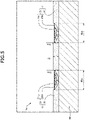
- Fig. 5 is an explanatory diagram illustrating a cross-sectional configuration of a guide wire 1A according to a second embodiment.
- the guide wire 1A includes a coating film 11, and the coating film 11 includes a marker portion 21 instead of the marker portion 20 of the first embodiment in Fig. 3 .
- the thickness Hm of the portion of the coating film 11 where the marker portion 21 is represented on the outer surface is smaller than the thickness Hr of the portion of the coating film 11 where the resin portion 30 is represented on the outer surface.
- the outer surface of the marker portion 21 is radially inside the core shaft 40 relative to the outer surface of the resin portion 30.
- the outer surface of the marker portion 21 does not easily contact an inner peripheral surface of a device used with the guide wire such as a catheter (not illustrated) or a wall surface (not illustrated) of an internal organ or a blood vessel of a body, and it is possible to decrease a possibility that the marker portion 21 peels off.
- a contact of an inner peripheral surface of the device used with the guide wire such as a catheter (not illustrated) and a wall surface (not illustrated) of an internal organ, a blood vessel, or the like of a body, with the outer surface of the marker portion 21 is not easy, but a contact thereof with the outer surface of the resin portion 30 is easier, and thus, it is possible to improve slidability of the guide wire 1A.
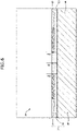
- Fig. 6 is an explanatory diagram illustrating a cross-sectional configuration of a guide wire 1B according to a third embodiment.
- the guide wire 1B includes a coating film 12, and the coating film 12 includes a marker portion 22 instead of the marker portion 20 of the first embodiment in Fig. 3 .
- a cross-sectional width of the marker portion 22 is substantially constant in a radial direction of the core shaft 40.
- the marker portion 22 has a substantially constant overall pigment content over the longitudinal section of the marker portion 22.
- the coating film 12 covers the outer surface of the core shaft 40 with the resin portion 30 having a groove formed in a wavy shape or a spiral shape toward the stretching direction of the core shaft 40, and may be formed by fitting the linearly formed marker portion 22 into the groove formed in the resin portion 30.
- the cross-sectional width of the marker portion decreases toward the inside of the core shaft 40 in the radial direction, it is possible to increase a thickness of an end portion of the marker portion 22, and thus, it is possible to prevent the marker portion 22 from being damaged starting from the end portion of the marker portion 22.
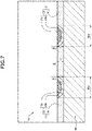
- Fig. 7 is an explanatory diagram illustrating a cross-sectional configuration of a guide wire 1C according to a fourth embodiment.
- the guide wire 1C includes a coating film 13, and the coating film 13 includes a marker portion 23 instead of the marker portion 20 of the first embodiment in Fig. 3 .
- An inner surface of the marker portion 23 contacts the outer surface of the core shaft 40.
- a maximum width of the marker portion 23 and the thickness Hm of a portion of the coating film 13 where the marker portion 23 is represented on the outer surface are equal.
- the configuration of the present embodiment as compared to a case where the inner surface of the marker portion does not contact the outer surface of the core shaft 40, it is possible to increase a thickness of the marker portion 23, and thus, a strength of the marker portion 23 is improved.
- the marker portions 20, 21, 22, and 23 (see Figs. 3 , 5 , 6 , and 7 ) of the first to fourth embodiments are displayed in a part (marker display zone) of the core shaft 40.
- the marker portions 20, 21, 22, and 23 may be formed over the entire core shaft 40.
- the marker portions 20, 21, 22, and 23 are assumed to be drawn with one pattern.
- the marker portions 20, 21, 22, and 23 may have a plurality of types of patterns.
- the marker portions 20, 21, 22, and 23 may have a mode in which the pattern changes continuously, or may have a different pattern for each predetermined zone.
- the marker portions 20, 21, 22, and 23 may be cut somewhere in the core shaft 40 and drawn at a plurality of locations.
- a plurality of types of patterns may be drawn at a plurality of locations at predetermined intervals, or an annular pattern may be continuously drawn at equal intervals.
- Fig. 8 illustrates a guide wire 1D which is a modification of the first to fourth embodiments.
- the guide wire 1D includes a coating film 14, and the coating film 14 includes a marker portion 24.
- An outer surface of the marker portion 24 is of arc shape and is recessed toward the inside of the core shaft 40 in the radial direction. Therefore, the thickness Hm of the portion of the coating film 14 where the marker portion 24 is represented on the outer surface is not substantially constant in the stretching direction of the core shaft 40.
- the thickness of the end portion of the marker portion 24 is a maximum value of the thickness of the portion of the coating film 14 where the marker portion 24 is represented on the outer surface.
- the outer surface of the marker portions 20, 21, 22, and 23 may be recessed toward the inside of the core shaft 40 in the radial direction. As long as the outer surface of the marker portions 20, 21, 22, and 23 does not protrude outward in the radial direction of the core shaft 40 from the outer surface of the resin, the outer surface of the marker portions 20, 21, 22, and 23 may be recessed outward in the radial direction of the core shaft 40.
- the guide wires 1, 1A, 1B, and 1C of the first to fourth embodiments are assumed to include the coil body 50 at the distal end. However, it is not required that the guide wires 1, 1A, 1B, and 1C include the coil body 50. In this case, the coating films 10, 11, 12, and 13 may be provided at the distal end portion of the core shaft 40.
Landscapes
- Health & Medical Sciences (AREA)
- Life Sciences & Earth Sciences (AREA)
- General Health & Medical Sciences (AREA)
- Animal Behavior & Ethology (AREA)
- Biophysics (AREA)
- Engineering & Computer Science (AREA)
- Biomedical Technology (AREA)
- Heart & Thoracic Surgery (AREA)
- Veterinary Medicine (AREA)
- Public Health (AREA)
- Hematology (AREA)
- Anesthesiology (AREA)
- Pulmonology (AREA)
- Surgery (AREA)
- Radiology & Medical Imaging (AREA)
- Physics & Mathematics (AREA)
- Molecular Biology (AREA)
- Medical Informatics (AREA)
- Pathology (AREA)
- Optics & Photonics (AREA)
- Nuclear Medicine, Radiotherapy & Molecular Imaging (AREA)
- Media Introduction/Drainage Providing Device (AREA)
Abstract
Description
- The disclosed embodiments relate to a guide wire.
- Conventionally, to observe a position or an orientation of a distal end of a guide wire inserted into a living lumen with an endoscopic camera, there is known a guide wire including a resin marker (visibility marker) provided on an outer surface of a wire main body (see
Patent Literature 1, for example). For example,Patent Literature 1 discloses a guide wire provided with a raised portion forming layer containing a resin and a pigment, the raised portion forming layer functioning as a visual recognition marker on an outer surface of the guide wire. - Patent Literature 1:
JP 5509276 - However, the guide wire described in
Patent Literature 1 has a problem in that an outer diameter of a portion of the guide wire where the marker is provided is larger than an outer diameter of a portion where the marker is not provided, and thus, there is a limit on a size of a catheter that can be used together with the guide wire. Another problem is that the marker protrudes radially outward from the resin portion, and thus, when contacting a device used together with the guide wire or an inner wall of a body cavity, the marker peels off. Still another problem is that if the outer diameter of the wire main body is reduced to suppress an increase in the outer diameter of the guide wire, the rigidity of the guide wire is reduced. - An object of the disclosed embodiments is to suppress an increase of an outer diameter of a guide wire due to provision of a marker on the guide wire in a guide wire provided with a marker containing a resin on an outer surface of a core shaft.
- The disclosed embodiments have been made to solve at least one of the above-described problems, and can be realized as the following aspects.
- (1) According to one aspect of the disclosed embodiments, a guide wire is provided. The guide wire includes a core shaft having an elongated outer shape, and a coating film formed on an outer surface of the core shaft, the coating film containing a resin, in which the coating film includes a marker portion containing a pigment and being linearly represented on an outer surface of the coating film and a resin portion that does not contain the pigment, and on the outer surface of the coating film, the marker portion and the resin portion are represented alternately in a stretching direction, of the coating film, a thickness of a portion where the marker portion is represented on the outer surface and a thickness of a portion where the resin portion is represented on the outer surface are substantially the same, or the thickness of the portion where the marker portion is represented is smaller than the thickness of the portion where the resin portion is represented.
According to such a configuration, of the coating film, the thickness of the portion where the marker portion is represented on the outer surface and the thickness of the portion where the resin portion is represented on the outer surface are substantially the same, or the thickness of the portion where the marker portion is represented on the outer surface is smaller than the thickness of the portion where the resin portion is represented on the outer surface, and thus, when the guide wire is provided with the marker, it is possible to suppress an increase of an outer diameter of the guide wire. - (2) In the guide wire of the above aspect, in a longitudinal section along a stretching direction of the core shaft, a cross-sectional width of the marker portion may decrease toward an inside of the core shaft in a radial direction. According to such a configuration, as compared to a case where the cross-sectional width of the marker portion is substantially constant toward the inside of the core shaft in the radial direction, it is possible to increase a contact area between the marker portion and the resin portion, and thus, it is possible to decrease a possibility that the marker portion and the resin portion peel of.
- (3) In the guide wire of the above aspect, the marker portion may include a first region including the outer surface of the marker portion and a second region provided around the first region, and a content of the second pigment may be smaller than a content of the first pigment. According to such a configuration, when the pigment content of the marker portion contacting the resin portion is reduced, it is possible to maintain adhesion between the marker portion and the resin portion and it is possible to decrease a possibility that the marker portion and the resin portion peel off.
- (4) In the guide wire of the above aspect, an average particle size of the pigment contained in the marker portion may be smaller than an average particle size of the resin. According to such a configuration, even if the resin portion is formed further to the distal side than the marker portion on the outer surface of the core shaft, when the pigment is heated on the resin portion, the pigment can impregnate the resin portion to form the marker portion.
- It is noted that the disclosed embodiments can be realized in various aspects, and may be realized in a mode such as a method of manufacturing a catheter, an endoscope, an image generation device, an inspection device, a treatment system, and a guide wire, for example.
-
-
Fig. 1 is an explanatory diagram illustrating an entire configuration of a guide wire according to a first embodiment. -
Fig. 2 is an explanatory diagram illustrating a cross-sectional configuration of the guide wire according to the first embodiment. -
Fig. 3 is an explanatory diagram obtained when an X portion ofFig. 2 is enlarged. -
Fig. 4 is an explanatory diagram illustrating a method of manufacturing the guide wire according to the first embodiment. -
Fig. 5 is an explanatory diagram illustrating a cross-sectional configuration of a guide wire according to a second embodiment. -
Fig. 6 is an explanatory diagram illustrating a cross-sectional configuration of a guide wire according to a third embodiment. -
Fig. 7 is an explanatory diagram illustrating a cross-sectional configuration of a guide wire according to a fourth embodiment. -
Fig. 8 is an explanatory diagram illustrating a modification of the guide wire according to the first to fourth embodiments. -
Fig. 1 is an explanatory diagram illustrating an entire configuration of aguide wire 1 according to a first embodiment.Fig. 2 is an explanatory diagram illustrating a cross-sectional configuration of theguide wire 1. Hereinafter, the left side inFig. 1 is referred to as "distal end side" of theguide wire 1 and constituent members, and the right side inFig. 1 is referred to as "proximal end side" of theguide wire 1 and constituent members. The distal end side of theguide wire 1 is a side to be inserted into a body (distal side), and the proximal end side of theguide wire 1 is a side operated by an operator such as a doctor (near side). The left-right direction inFIG. 1 is referred to as "stretching direction" or "axis direction" of theguide wire 1 and each constituent member.Fig. 2 illustrates a longitudinal section along the stretching direction of theguide wire 1. Theguide wire 1 is a medical device used when a catheter is inserted into a blood vessel or a digestive organ, and includes acoating film 10, acore shaft 40, acoil body 50, a distal endside joint portion 60, and a proximal endside joint portion 70. - The
core shaft 40 has an elongated shape, and thecoating film 10 is formed on the outer surface of thecore shaft 40. Thecoating film 10 includes amarker portion 20 and aresin portion 30. Thecoil body 50 is wound around an outer periphery of the distal end portion of thecore shaft 40. - The
core shaft 40 is an elongated (tapered) member configured so that an outer diameter decreases from the proximal end side to the distal end side. Thecore shaft 40 may be formed of a material such as a stainless alloy (SUS302, SUS304, SUS316, and the like), a superelastic alloy such as an Ni-Ti alloy, a piano wire, a nickel-chromium base alloy, a cobalt alloy, and tungsten. Thecore shaft 40 may be formed of a well-known material other than the materials mentioned above. A length of thecore shaft 40 is not particularly limited, but a range of 1000 mm to 5000 mm may be used as an example. The outer diameter of thecore shaft 40 is also not particularly limited, but a range of 0.1 mm to 1.0 mm may be used as an example. - The
coil body 50 is configured by one or a plurality of coils, and is wound around thecore shaft 40 to cover the outer periphery on the distal end side of thecore shaft 40. Here, thecoil body 50 is wound around a part of a small diameter portion and a tapered portion on the distal end side of thecore shaft 40. The coil configuring thecoil body 50 may be a single coil formed by spirally winding one wire having a circular cross section to form a cylindrical shape, or a hollow, twisted wire coil obtained by forming a twisted wire obtained by twisting a plurality of wires into a cylindrical shape. Thecoil body 50 may be configured by combining a single coil and a hollow twisted wire coil. Thecoil body 50 may be formed of, for example, a stainless alloy (SUS302, SUS304, SUS316, and the like), a superelastic alloy such as an Ni-Ti alloy, a piano wire, a nickel-chromium base alloy, a cobalt alloy, a radiolucent alloy such as tungsten, gold, platinum, tungsten, and a radiopaque alloy such as an alloy containing these elements (for example, a platinum-nickel alloy). Thecoil body 50 may be formed of a well-known material other than the materials mentioned above. A length of thecoil body 50 is not particularly limited, but for example, 10 mm to 100 mm may be used as an example. An outer diameter of thecoil body 50 is not particularly limited, but may be in a range of 0.1 mm to 1.0 mm, for example, and is configured to be constant from the distal end to the proximal end. Thecoil body 50 may include a loosely wound portion and a tightly wound portion having different coil pitches. - The distal end of the
coil body 50 is joined to the distal end of thecore shaft 40 by the distal endside joint portion 60. The proximal end of thecoil body 50 is joined to thecore shaft 40 by the proximal endside joint portion 70. Thecoil body 50 is fixed to thecore shaft 40 by the distal endside joint portion 60 and the proximal endside joint portion 70. The distal endside joint portion 60 and the proximal endside joint portion 70 are formed of a metal solder such as silver solder, gold solder, zinc, a Sn-Ag alloy, and an Au-Sn alloy, and by such a metal solder, thecoil body 50 and thecore shaft 40 are adhered and fixed. It is noted that the distal endside joint portion 60 and the proximal endside joint portion 70 may be formed of an adhesive such as an epoxy adhesive, and by such an adhesive, thecoil body 60 and thecore shaft 20 may be adhered and fixed. The distal endside joint portion 60 and the proximal endside joint portion 70 may be formed of different materials. - The
coating film 10 is formed on the outer surface of thecore shaft 40, and includes themarker portion 20 and theresin portion 30. Thecoating film 10 is arranged on the proximal end side of thecore shaft 40 relative to the proximal end sidejoint portion 70. In thecoating film 10, a length of a zone where themarker portion 20 is formed (marker display zone) is not particularly limited, but a range of 100 mm to 500 mm may be used as an example. Thecoating film 10 may cover not only the outer surface of thecore shaft 40 on the proximal end side relative to the proximal end sidejoint portion 70, but also the proximal end sidejoint portion 70, thecoil body 50, and the distal end sidejoint portion 60. - The
marker portion 20 contains a pigment and is formed on the outer surface of thecore shaft 40. Themarker portion 20 forms a part of the outer surface of thecoating film 10. Themarker portion 20 is a linear site formed in a part of thecoating film 10, and is configured to be visually distinguishable from theresin portion 30. When theguide wire 1 is observed from outside, themarker portion 20 is seen as a linear pattern on theguide wire 1, and when the operator observes a change of an orientation and a position of the pattern when operating theguide wire 1, it is possible to confirm push-pull and rotation operations of theguide wire 1. - The
marker portion 20 is formed to have a wavy pattern in a developed view obtained when the outer periphery of thecore shaft 40 is expanded. That is, when the pigment dripping toward thecore shaft 40 is moved along the stretching direction in a state where thecore shaft 40 is reciprocated and rotated by a predetermined angle (for example, 180°) to the left and right with the stretching direction (axis direction) as a rotation axis, it is possible to from such a wavy pattern. Themarker portion 40 may be spirally formed on thecore shaft 40. That is, when the pigment dripping toward thecore shaft 40 is moved along the stretching direction in a state where thecore shaft 40 is rotated in one direction with the stretching direction (axis direction) as a rotation axis, it is possible to from a spiral pattern. - The pigment forming the
marker portion 20 may be any one of an inorganic pigment and an organic pigment, but it is preferable to use an inorganic pigment in terms of heat resistance. As the inorganic pigment, it is possible to use carbon black, mica, titanium dioxide, titanium yellow, Prussian blue, Milori blue, cobalt blue, ultramarine, viridian, and the like. Themarker portion 20 may contain a resin, and may contain PAI (polyamide-imide), PTFE (polytetrafluoroethylene), PVDF (polyvinylidene fluoride), PFA (perfluoroalkoxy alkane), FEP (perfluoroethylene propene), ETFE (ethylene tetrafluoroethylene), PE (polyethylene), and PP (polypropylene), for example. Themarker portion 30 may be formed of a well-known material other than the above examples. Themarker portion 20 may contain the same type of resin as or a type different from the resin forming theresin portion 30. - The
resin portion 30 contains a resin and is formed on the outer surface of thecore shaft 40. Theresin portion 30 forms a part of the outer surface of thecoating film 10. - The
resin portion 30 may be formed of PAI (polyamide-imide), PTFE (polytetrafluoroethylene), PVDF (polyvinylidene fluoride), PFA (perfluoroalkoxy alkane), FEP (perfluoroethylene propene), ETFE (ethylene tetrafluoroethylene), PE (polyethylene), and PP (polypropylene), for example. Theresin portion 30 may be formed of a well-known material other than the above examples. Theresin portion 30 may contain a pigment, which may be any one of an inorganic pigment and an organic pigment, but it is preferable to use the inorganic pigment in terms of heat resistance. As the inorganic pigment, it is possible to use carbon black, mica, titanium dioxide, titanium yellow, Prussian blue, Milori blue, cobalt blue, ultramarine, viridian, and the like. When theresin portion 30 is formed to be different in color from themarker portion 20, it is possible to increase the visibility of themarker portion 20. - The
marker portion 20 and theresin portion 30 are repeatedly represented as a result of themarker portion 20 and theresin portion 30 being alternately and continuously present without gaps along the stretching direction of theguide wire 1. -
Fig. 3 is an explanatory diagram obtained when an X portion ofFig. 2 is enlarged. The X portion is a portion located on the proximal end side relative to the proximal end sidejoint portion 70 inFig. 2 and provided with thecoating film 10 on the outer surface of thecore shaft 40, and is provided with themarker portion 20. The X portion is used as an example to describe a detailed configuration of themarker portion 20 and theresin portion 30. - A thickness of a portion of the
coating film 10 where themarker portion 20 is represented on the outer surface is defined as Hm. It is assumed here that the thickness Hm is a maximum value of a length from the outer surface of themarker portion 20 to the outer surface of thecore shaft 40 in the longitudinal section of thecore shaft 40. The thickness Hm is not particularly limited, but a range of 0.01 mm to 0.1 mm may be used as an example. InFig. 3 , the outer surface of themarker portion 20 is flat, and thus, the thickness Hm remains substantially the same at any point in the stretching direction of thecore shaft 40. - In the longitudinal section of the
core shaft 40, a thickness of a portion of thecoating film 10 in which theresin portion 30 is represented on the outer surface, the portion existing between adjacent ones of themarker portions 20, is defined as Hr. It is assumed here that the thickness Hr is a maximum value of a length from the outer surface of theresin portion 30 to the outer surface of thecore shaft 40 in the longitudinal section of thecore shaft 40. The thickness Hr is not particularly limited, but a range of 0.01 mm to 0.1 mm may be used as an example. InFig. 3 , the outer surface of theresin portion 30 is flat, and thus, the thickness Hr remains substantially the same at any point in the stretching direction of thecore shaft 40. - The thickness Hm of the portion of the
coating film 10 where themarker portion 20 is represented on the outer surface is substantially the same as the thickness Hr of the portion of thecoating film 10 where theresin portion 30 is represented on the outer surface. In other words, the outer surface of themarker portion 20 and the outer surface of theresin portion 30 are formed to be flat. For example, it is preferable that a difference between the thickness Hm and the thickness Hr is equal to or less than 20 pm, and more preferably equal to or less than 10 pm. - In the longitudinal section of the
core shaft 40, a length of themarker portion 20 in the stretching direction of thecore shaft 40 is defined as a cross-sectional width of themarker portion 20. Further, the cross-sectional width of themarker portion 20 on the outer surface of themarker portion 20 is defined as an outer cross-sectional width Wm. Themarker portion 20 is of arc shape, and of convex shape inward in a radial direction of thecore shaft 40, and thus, the cross-sectional width of themarker portion 20 gradually decreases inward in the radial direction of thecore shaft 40. In other words, the cross-sectional width of themarker portion 20 gradually increases outward in the radial direction of thecore shaft 40. - The
marker portion 20 includes afirst region 20a including the outer surface of themarker portion 20 and asecond region 20b provided around thefirst region 20a. In the longitudinal section of thecore shaft 40, thefirst region 20a is of arc shape, and is of convex shape toward the inside of thecore shaft 40 in the radial direction. Thesecond region 20b is of arc shape to cover a surrounding area of the first region, and is of convex shape toward the inside of thecore shaft 40 in the radial direction. Here, a content of the pigment contained in thesecond region 20b is smaller than a content of the pigment contained in thefirst region 20a. If themarker portion 20 is configured by the resin and the pigment, the content of the pigment contained in thesecond region 20b is larger than the content of the pigment contained in thefirst region 20a. -
Fig. 4 is an explanatory diagram illustrating a method of manufacturing theguide wire 1. If an average particle size of apigment 100 contained in themarker portion 20 is smaller than an average particle size of the resin of theresin portion 30, it is possible to manufacture themarker portion 20 represented by a wavy pattern on theresin portion 30 according to the following steps, for example. Firstly, theresin portion 30 is coated on the outer surface of thecore shaft 40. Next, in a state where thecore shaft 40 is reciprocated and rotated by a predetermined angle (for example, 180°) to the left and right with the stretching direction (axis direction) as a rotation axis, thepigment 100 dripping toward thecore shaft 40 is moved along the stretching direction. As a result, thepigment 100 is applied in a wavy pattern on the outer surface of theresin portion 30. Next, when thepigment 100 is heated with a heater or the like, particles of thepigment 100 enter between particles of theresin portion 30. Finally, when thepigment 100 and theresin portion 30 are dried, thepigment 100 and theresin portion 30 are fixed, and thecoating film 10 is formed. According to this method, themarker portion 20 is formed in an arc shape to be convex toward the inside of thecore shaft 40 in the radial direction around a point where thepigment 100 is applied. As a result, in themarker portion 20, in an area near the point where thepigment 100 is applied, a content of thepigment 100 is large, and the content of thepigment 100 gradually decreases as a distance from the point where thepigment 100 is applied increases. According to such a procedure, it is possible to form thefirst region 20a and thesecond region 20b. - According to the configuration of the present embodiment, when the
guide wire 1 is provided with themarker portion 20, it is possible to suppress an increase of the outer diameter of theguide wire 1. When the increase of the outer diameter of theguide wire 1 is suppressed, the operator is capable of selecting a device having a smaller inner diameter of a lumen in using a device used with the guide wire such as a catheter having a lumen through which the guide wire is inserted. It is also easier for the operator to insert the guide wire into a site having a small diameter such as a peripheral blood vessel. - According to the configuration of the present embodiment, as compared to a case where the cross-sectional width of the
marker portion 20 is substantially constant toward the inside of thecore shaft 40 in the radial direction, it is possible to increase a contact area between themarker portion 20 and theresin portion 30, and thus, it is possible to decrease a possibility that themarker portion 20 and theresin portion 30 peel off. As a result, it is possible to prevent themarker portion 20 from peeling off and remaining in a body of a patient or in the device used with the guide wire such as a catheter. - According to the configuration of the present embodiment, when the content of pigment contained in a marker portion 20C contacting the
resin portion 30 is reduced, it is possible to maintain adhesion between the marker portion 20C and theresin portion 30 and it is possible to decrease a possibility that the marker portion 20C and theresin portion 30 peel off. -
Fig. 5 is an explanatory diagram illustrating a cross-sectional configuration of aguide wire 1A according to a second embodiment. Theguide wire 1A includes acoating film 11, and thecoating film 11 includes amarker portion 21 instead of themarker portion 20 of the first embodiment inFig. 3 . The thickness Hm of the portion of thecoating film 11 where themarker portion 21 is represented on the outer surface is smaller than the thickness Hr of the portion of thecoating film 11 where theresin portion 30 is represented on the outer surface. In other words, the outer surface of themarker portion 21 is radially inside thecore shaft 40 relative to the outer surface of theresin portion 30. - According to the configuration of the present embodiment, the outer surface of the
marker portion 21 does not easily contact an inner peripheral surface of a device used with the guide wire such as a catheter (not illustrated) or a wall surface (not illustrated) of an internal organ or a blood vessel of a body, and it is possible to decrease a possibility that themarker portion 21 peels off. A contact of an inner peripheral surface of the device used with the guide wire such as a catheter (not illustrated) and a wall surface (not illustrated) of an internal organ, a blood vessel, or the like of a body, with the outer surface of themarker portion 21 is not easy, but a contact thereof with the outer surface of theresin portion 30 is easier, and thus, it is possible to improve slidability of theguide wire 1A. -
Fig. 6 is an explanatory diagram illustrating a cross-sectional configuration of aguide wire 1B according to a third embodiment. Theguide wire 1B includes acoating film 12, and thecoating film 12 includes amarker portion 22 instead of themarker portion 20 of the first embodiment inFig. 3 . In themarker portion 22, a cross-sectional width of themarker portion 22 is substantially constant in a radial direction of thecore shaft 40. Themarker portion 22 has a substantially constant overall pigment content over the longitudinal section of themarker portion 22. For example, thecoating film 12 covers the outer surface of thecore shaft 40 with theresin portion 30 having a groove formed in a wavy shape or a spiral shape toward the stretching direction of thecore shaft 40, and may be formed by fitting the linearly formedmarker portion 22 into the groove formed in theresin portion 30. - According to the configuration of the present embodiment, as compared to a case where the cross-sectional width of the marker portion decreases toward the inside of the
core shaft 40 in the radial direction, it is possible to increase a thickness of an end portion of themarker portion 22, and thus, it is possible to prevent themarker portion 22 from being damaged starting from the end portion of themarker portion 22. -
Fig. 7 is an explanatory diagram illustrating a cross-sectional configuration of a guide wire 1C according to a fourth embodiment. The guide wire 1C includes acoating film 13, and thecoating film 13 includes a marker portion 23 instead of themarker portion 20 of the first embodiment inFig. 3 . An inner surface of the marker portion 23 contacts the outer surface of thecore shaft 40. In this case, a maximum width of the marker portion 23 and the thickness Hm of a portion of thecoating film 13 where the marker portion 23 is represented on the outer surface are equal. - According to the configuration of the present embodiment, as compared to a case where the inner surface of the marker portion does not contact the outer surface of the
core shaft 40, it is possible to increase a thickness of the marker portion 23, and thus, a strength of the marker portion 23 is improved. - The disclosed embodiments are not limited to the above-described embodiments, and may be implemented in various modes without departing from the spirit of the disclosed embodiments. The following modifications can be applied, for example.
- It is assumed that the
marker portions Figs. 3 ,5 ,6 , and7 ) of the first to fourth embodiments are displayed in a part (marker display zone) of thecore shaft 40. However, themarker portions entire core shaft 40. Themarker portions marker portions marker portions marker portions core shaft 40 and drawn at a plurality of locations. For example, in themarker portions -
Fig. 8 illustrates aguide wire 1D which is a modification of the first to fourth embodiments. Theguide wire 1D includes acoating film 14, and thecoating film 14 includes amarker portion 24. An outer surface of themarker portion 24 is of arc shape and is recessed toward the inside of thecore shaft 40 in the radial direction. Therefore, the thickness Hm of the portion of thecoating film 14 where themarker portion 24 is represented on the outer surface is not substantially constant in the stretching direction of thecore shaft 40. In the case ofFig. 8 , the thickness of the end portion of themarker portion 24 is a maximum value of the thickness of the portion of thecoating film 14 where themarker portion 24 is represented on the outer surface. In themarker portions core shaft 40, similarly to themarker portion 24, the outer surface of themarker portions core shaft 40 in the radial direction. As long as the outer surface of themarker portions core shaft 40 from the outer surface of the resin, the outer surface of themarker portions core shaft 40. - The
guide wires coil body 50 at the distal end. However, it is not required that theguide wires coil body 50. In this case, the coatingfilms core shaft 40. - Although the aspects have been described based on the embodiments and the modifications, the embodiments of the above-described aspects are for facilitating understanding of the aspects, and do not limit the aspects. The aspects can be modified and improved without departing from the spirit of the aspects and the scope of the claims, and equivalent aspects are included in the aspects. Further, unless a technical feature is described as essential in the present specification, it may be omitted as appropriate.
-
- 1, 1A, 1B, 1C ... Guide wire
- 10, 11, 12, 13 ... Coating film
- 20, 21, 22, 23 ... Marker portion
- 30 ... Resin portion
- 40 ... Core shaft
- 50 ... Coil body
- 60 ... Distal end side joint portion
- 70 ... Proximal end side joint portion
- 100 ... Pigment
- Hm ... Thickness of portion where marker portion is represented on outer surface
- Hr ... Thickness of portion where resin portion is represented on outer surface
- Wm ... Outer cross-sectional width of marker portion
Claims (4)
- A guide wire comprising:a core shaft having an elongated outer shape; anda coating film formed on an outer surface of the core shaft, the coating film containing a resin, whereinthe coating film includes a marker portion that contains a pigment linearly represented on an outer surface of the coating film and a resin portion that does not contain the pigment,on the outer surface of the coating film, the marker portion and the resin portion are alternately represented in a stretching direction, andof the coating film, a thickness of a portion where the marker portion is represented on the outer surface and a thickness of a portion where the resin portion is represented on the outer surface are substantially the same, or the thickness of the portion where the marker portion is represented is smaller than the thickness of the portion where the resin portion is represented.
- The guide wire according to claim 1, wherein
in a longitudinal section along a stretching direction of the core shaft, a cross-sectional width of the marker portion decreases toward an inside of the core shaft in a radial direction. - The guide wire according to claim 1 or claim 2, whereinthe marker portion includes a first region including the outer surface of the marker portion and a second region provided around the first region, anda content of the second pigment is smaller than a content of the first pigment.
- The guide wire according to any one of claims 1 to 3, wherein
an average particle size of the pigment contained in the marker portion is smaller than an average particle size of the resin.
Applications Claiming Priority (2)
| Application Number | Priority Date | Filing Date | Title |
|---|---|---|---|
| JP2020025802A JP7511355B2 (en) | 2020-02-19 | 2020-02-19 | Guidewires |
| PCT/JP2020/043586 WO2021166355A1 (en) | 2020-02-19 | 2020-11-24 | Guide wire |
Publications (3)
| Publication Number | Publication Date |
|---|---|
| EP4108284A1 true EP4108284A1 (en) | 2022-12-28 |
| EP4108284A4 EP4108284A4 (en) | 2024-03-20 |
| EP4108284B1 EP4108284B1 (en) | 2025-06-18 |
Family
ID=77391717
Family Applications (1)
| Application Number | Title | Priority Date | Filing Date |
|---|---|---|---|
| EP20919670.8A Active EP4108284B1 (en) | 2020-02-19 | 2020-11-24 | Guide wire |
Country Status (5)
| Country | Link |
|---|---|
| US (1) | US20220347441A1 (en) |
| EP (1) | EP4108284B1 (en) |
| JP (1) | JP7511355B2 (en) |
| CN (1) | CN115003362B (en) |
| WO (1) | WO2021166355A1 (en) |
Families Citing this family (2)
| Publication number | Priority date | Publication date | Assignee | Title |
|---|---|---|---|---|
| US20230123450A1 (en) * | 2021-10-05 | 2023-04-20 | Olympus Medical Systems Corp. | Medical apparatus with embedded marking |
| JP2026020678A (en) * | 2024-07-29 | 2026-02-10 | グンゼ株式会社 | Medical Guidewires |
Family Cites Families (8)
| Publication number | Priority date | Publication date | Assignee | Title |
|---|---|---|---|---|
| US5941706A (en) * | 1997-10-20 | 1999-08-24 | Ura; Robert S. | Variable depth medical drill and method of making the same |
| US6285903B1 (en) * | 1998-06-30 | 2001-09-04 | Eclipse Surgical Technologies, Inc. | Intracorporeal device with radiopaque marker |
| JP4271471B2 (en) * | 2003-03-27 | 2009-06-03 | テルモ株式会社 | Guide wire |
| JP5249591B2 (en) * | 2007-03-23 | 2013-07-31 | テルモ株式会社 | Guide wire |
| US8540648B2 (en) * | 2008-03-11 | 2013-09-24 | Epflex Feinwerktechnik Gmbh | Guide wire with marking pattern |
| WO2010018762A1 (en) * | 2008-08-11 | 2010-02-18 | テルモ株式会社 | Medical instrument |
| JP6178188B2 (en) * | 2013-09-26 | 2017-08-09 | テルモ株式会社 | MEDICAL DEVICE AND MEDICAL DEVICE MANUFACTURING METHOD |
| CN115430010A (en) * | 2018-02-09 | 2022-12-06 | 郡是株式会社 | Guide wire |
-
2020
- 2020-02-19 JP JP2020025802A patent/JP7511355B2/en active Active
- 2020-11-24 EP EP20919670.8A patent/EP4108284B1/en active Active
- 2020-11-24 CN CN202080094296.1A patent/CN115003362B/en active Active
- 2020-11-24 WO PCT/JP2020/043586 patent/WO2021166355A1/en not_active Ceased
-
2022
- 2022-07-19 US US17/867,684 patent/US20220347441A1/en active Pending
Also Published As
| Publication number | Publication date |
|---|---|
| EP4108284B1 (en) | 2025-06-18 |
| CN115003362A (en) | 2022-09-02 |
| WO2021166355A1 (en) | 2021-08-26 |
| JP7511355B2 (en) | 2024-07-05 |
| JP2021129679A (en) | 2021-09-09 |
| CN115003362B (en) | 2024-07-19 |
| EP4108284A4 (en) | 2024-03-20 |
| US20220347441A1 (en) | 2022-11-03 |
Similar Documents
| Publication | Publication Date | Title |
|---|---|---|
| EP3546008B1 (en) | Catheter and method for manufacturing catheter | |
| CN112672780B (en) | Catheter support frame with variable flexibility | |
| CN102112175B (en) | Medical instrument | |
| US11890428B2 (en) | Catheter | |
| US11633567B2 (en) | Catheter and balloon catheter | |
| US20220347441A1 (en) | Guide wire | |
| EP2937110A1 (en) | Medical device | |
| CN108348726A (en) | Catheter shaft and associated devices, systems, and methods | |
| JP7659106B2 (en) | Guidewires | |
| US20220054802A1 (en) | Guide wire | |
| US20230201525A1 (en) | Catheter | |
| EP3646916A1 (en) | Catheter, separator, and suction system | |
| WO2020246037A1 (en) | Guidewire | |
| EP3744379B1 (en) | Catheter | |
| JP7746717B2 (en) | Catheter, catheter manufacturing method, and contrast marker crimping method | |
| JP2024041089A (en) | catheter shaft | |
| JP2019024919A (en) | catheter | |
| EP3546012B1 (en) | Medical instrument | |
| US20250295887A1 (en) | Catheter | |
| JP2023137533A (en) | Catheter and manufacturing method of tubular shaft | |
| JP5614508B1 (en) | CATHETER AND METHOD FOR PRODUCING CATHETER | |
| WO2023095694A1 (en) | Catheter | |
| WO2024232141A1 (en) | Medical device |
Legal Events
| Date | Code | Title | Description |
|---|---|---|---|
| STAA | Information on the status of an ep patent application or granted ep patent |
Free format text: STATUS: THE INTERNATIONAL PUBLICATION HAS BEEN MADE |
|
| PUAI | Public reference made under article 153(3) epc to a published international application that has entered the european phase |
Free format text: ORIGINAL CODE: 0009012 |
|
| STAA | Information on the status of an ep patent application or granted ep patent |
Free format text: STATUS: REQUEST FOR EXAMINATION WAS MADE |
|
| 17P | Request for examination filed |
Effective date: 20220713 |
|
| AK | Designated contracting states |
Kind code of ref document: A1 Designated state(s): AL AT BE BG CH CY CZ DE DK EE ES FI FR GB GR HR HU IE IS IT LI LT LU LV MC MK MT NL NO PL PT RO RS SE SI SK SM TR |
|
| DAV | Request for validation of the european patent (deleted) | ||
| DAX | Request for extension of the european patent (deleted) | ||
| A4 | Supplementary search report drawn up and despatched |
Effective date: 20240220 |
|
| RIC1 | Information provided on ipc code assigned before grant |
Ipc: A61B 1/01 20060101ALI20240214BHEP Ipc: A61M 25/09 20060101AFI20240214BHEP |
|
| GRAP | Despatch of communication of intention to grant a patent |
Free format text: ORIGINAL CODE: EPIDOSNIGR1 |
|
| STAA | Information on the status of an ep patent application or granted ep patent |
Free format text: STATUS: GRANT OF PATENT IS INTENDED |
|
| RIC1 | Information provided on ipc code assigned before grant |
Ipc: A61B 1/01 20060101ALI20241108BHEP Ipc: A61M 25/09 20060101AFI20241108BHEP |
|
| INTG | Intention to grant announced |
Effective date: 20241120 |
|
| GRAJ | Information related to disapproval of communication of intention to grant by the applicant or resumption of examination proceedings by the epo deleted |
Free format text: ORIGINAL CODE: EPIDOSDIGR1 |
|
| STAA | Information on the status of an ep patent application or granted ep patent |
Free format text: STATUS: REQUEST FOR EXAMINATION WAS MADE |
|
| GRAP | Despatch of communication of intention to grant a patent |
Free format text: ORIGINAL CODE: EPIDOSNIGR1 |
|
| STAA | Information on the status of an ep patent application or granted ep patent |
Free format text: STATUS: GRANT OF PATENT IS INTENDED |
|
| INTC | Intention to grant announced (deleted) | ||
| INTG | Intention to grant announced |
Effective date: 20250218 |
|
| GRAS | Grant fee paid |
Free format text: ORIGINAL CODE: EPIDOSNIGR3 |
|
| GRAA | (expected) grant |
Free format text: ORIGINAL CODE: 0009210 |
|
| STAA | Information on the status of an ep patent application or granted ep patent |
Free format text: STATUS: THE PATENT HAS BEEN GRANTED |
|
| AK | Designated contracting states |
Kind code of ref document: B1 Designated state(s): AL AT BE BG CH CY CZ DE DK EE ES FI FR GB GR HR HU IE IS IT LI LT LU LV MC MK MT NL NO PL PT RO RS SE SI SK SM TR |
|
| REG | Reference to a national code |
Ref country code: GB Ref legal event code: FG4D |
|
| REG | Reference to a national code |
Ref country code: CH Ref legal event code: EP |
|
| REG | Reference to a national code |
Ref country code: DE Ref legal event code: R096 Ref document number: 602020053110 Country of ref document: DE |
|
| REG | Reference to a national code |
Ref country code: CH Ref legal event code: EP |
|
| REG | Reference to a national code |
Ref country code: IE Ref legal event code: FG4D |
|
| PG25 | Lapsed in a contracting state [announced via postgrant information from national office to epo] |
Ref country code: FI Free format text: LAPSE BECAUSE OF FAILURE TO SUBMIT A TRANSLATION OF THE DESCRIPTION OR TO PAY THE FEE WITHIN THE PRESCRIBED TIME-LIMIT Effective date: 20250618 |
|
| REG | Reference to a national code |
Ref country code: LT Ref legal event code: MG9D |
|
| PG25 | Lapsed in a contracting state [announced via postgrant information from national office to epo] |
Ref country code: GR Free format text: LAPSE BECAUSE OF FAILURE TO SUBMIT A TRANSLATION OF THE DESCRIPTION OR TO PAY THE FEE WITHIN THE PRESCRIBED TIME-LIMIT Effective date: 20250919 Ref country code: NO Free format text: LAPSE BECAUSE OF FAILURE TO SUBMIT A TRANSLATION OF THE DESCRIPTION OR TO PAY THE FEE WITHIN THE PRESCRIBED TIME-LIMIT Effective date: 20250918 |
|
| PG25 | Lapsed in a contracting state [announced via postgrant information from national office to epo] |
Ref country code: BG Free format text: LAPSE BECAUSE OF FAILURE TO SUBMIT A TRANSLATION OF THE DESCRIPTION OR TO PAY THE FEE WITHIN THE PRESCRIBED TIME-LIMIT Effective date: 20250618 |
|
| PG25 | Lapsed in a contracting state [announced via postgrant information from national office to epo] |
Ref country code: HR Free format text: LAPSE BECAUSE OF FAILURE TO SUBMIT A TRANSLATION OF THE DESCRIPTION OR TO PAY THE FEE WITHIN THE PRESCRIBED TIME-LIMIT Effective date: 20250618 |
|
| PG25 | Lapsed in a contracting state [announced via postgrant information from national office to epo] |
Ref country code: RS Free format text: LAPSE BECAUSE OF FAILURE TO SUBMIT A TRANSLATION OF THE DESCRIPTION OR TO PAY THE FEE WITHIN THE PRESCRIBED TIME-LIMIT Effective date: 20250918 |
|
| REG | Reference to a national code |
Ref country code: NL Ref legal event code: MP Effective date: 20250618 |
|
| PG25 | Lapsed in a contracting state [announced via postgrant information from national office to epo] |
Ref country code: LV Free format text: LAPSE BECAUSE OF FAILURE TO SUBMIT A TRANSLATION OF THE DESCRIPTION OR TO PAY THE FEE WITHIN THE PRESCRIBED TIME-LIMIT Effective date: 20250618 |
|
| PG25 | Lapsed in a contracting state [announced via postgrant information from national office to epo] |
Ref country code: NL Free format text: LAPSE BECAUSE OF FAILURE TO SUBMIT A TRANSLATION OF THE DESCRIPTION OR TO PAY THE FEE WITHIN THE PRESCRIBED TIME-LIMIT Effective date: 20250618 |
|
| REG | Reference to a national code |
Ref country code: CH Ref legal event code: U11 Free format text: ST27 STATUS EVENT CODE: U-0-0-U10-U11 (AS PROVIDED BY THE NATIONAL OFFICE) Effective date: 20251201 |
|
| PG25 | Lapsed in a contracting state [announced via postgrant information from national office to epo] |
Ref country code: PT Free format text: LAPSE BECAUSE OF FAILURE TO SUBMIT A TRANSLATION OF THE DESCRIPTION OR TO PAY THE FEE WITHIN THE PRESCRIBED TIME-LIMIT Effective date: 20251020 |
|
| REG | Reference to a national code |
Ref country code: AT Ref legal event code: MK05 Ref document number: 1803652 Country of ref document: AT Kind code of ref document: T Effective date: 20250618 |
|
| PG25 | Lapsed in a contracting state [announced via postgrant information from national office to epo] |
Ref country code: IS Free format text: LAPSE BECAUSE OF FAILURE TO SUBMIT A TRANSLATION OF THE DESCRIPTION OR TO PAY THE FEE WITHIN THE PRESCRIBED TIME-LIMIT Effective date: 20251018 |
|
| PGFP | Annual fee paid to national office [announced via postgrant information from national office to epo] |
Ref country code: DE Payment date: 20251119 Year of fee payment: 6 |
|
| PGFP | Annual fee paid to national office [announced via postgrant information from national office to epo] |
Ref country code: GB Payment date: 20251121 Year of fee payment: 6 |
|
| PG25 | Lapsed in a contracting state [announced via postgrant information from national office to epo] |
Ref country code: AT Free format text: LAPSE BECAUSE OF FAILURE TO SUBMIT A TRANSLATION OF THE DESCRIPTION OR TO PAY THE FEE WITHIN THE PRESCRIBED TIME-LIMIT Effective date: 20250618 Ref country code: SM Free format text: LAPSE BECAUSE OF FAILURE TO SUBMIT A TRANSLATION OF THE DESCRIPTION OR TO PAY THE FEE WITHIN THE PRESCRIBED TIME-LIMIT Effective date: 20250618 |
|
| PGFP | Annual fee paid to national office [announced via postgrant information from national office to epo] |
Ref country code: FR Payment date: 20251126 Year of fee payment: 6 |
|
| PGFP | Annual fee paid to national office [announced via postgrant information from national office to epo] |
Ref country code: CH Payment date: 20251201 Year of fee payment: 6 |
|
| PG25 | Lapsed in a contracting state [announced via postgrant information from national office to epo] |
Ref country code: CZ Free format text: LAPSE BECAUSE OF FAILURE TO SUBMIT A TRANSLATION OF THE DESCRIPTION OR TO PAY THE FEE WITHIN THE PRESCRIBED TIME-LIMIT Effective date: 20250618 |
|
| PG25 | Lapsed in a contracting state [announced via postgrant information from national office to epo] |
Ref country code: PL Free format text: LAPSE BECAUSE OF FAILURE TO SUBMIT A TRANSLATION OF THE DESCRIPTION OR TO PAY THE FEE WITHIN THE PRESCRIBED TIME-LIMIT Effective date: 20250618 |
|
| PG25 | Lapsed in a contracting state [announced via postgrant information from national office to epo] |
Ref country code: EE Free format text: LAPSE BECAUSE OF FAILURE TO SUBMIT A TRANSLATION OF THE DESCRIPTION OR TO PAY THE FEE WITHIN THE PRESCRIBED TIME-LIMIT Effective date: 20250618 |
|
| PG25 | Lapsed in a contracting state [announced via postgrant information from national office to epo] |
Ref country code: SK Free format text: LAPSE BECAUSE OF FAILURE TO SUBMIT A TRANSLATION OF THE DESCRIPTION OR TO PAY THE FEE WITHIN THE PRESCRIBED TIME-LIMIT Effective date: 20250618 |
|
| PG25 | Lapsed in a contracting state [announced via postgrant information from national office to epo] |
Ref country code: ES Free format text: LAPSE BECAUSE OF FAILURE TO SUBMIT A TRANSLATION OF THE DESCRIPTION OR TO PAY THE FEE WITHIN THE PRESCRIBED TIME-LIMIT Effective date: 20250618 |
|
| PG25 | Lapsed in a contracting state [announced via postgrant information from national office to epo] |
Ref country code: RO Free format text: LAPSE BECAUSE OF FAILURE TO SUBMIT A TRANSLATION OF THE DESCRIPTION OR TO PAY THE FEE WITHIN THE PRESCRIBED TIME-LIMIT Effective date: 20250618 |
|
| REG | Reference to a national code |
Ref country code: DE Ref legal event code: R097 Ref document number: 602020053110 Country of ref document: DE |
|
| PG25 | Lapsed in a contracting state [announced via postgrant information from national office to epo] |
Ref country code: DK Free format text: LAPSE BECAUSE OF FAILURE TO SUBMIT A TRANSLATION OF THE DESCRIPTION OR TO PAY THE FEE WITHIN THE PRESCRIBED TIME-LIMIT Effective date: 20250618 |
|
| PG25 | Lapsed in a contracting state [announced via postgrant information from national office to epo] |
Ref country code: IT Free format text: LAPSE BECAUSE OF FAILURE TO SUBMIT A TRANSLATION OF THE DESCRIPTION OR TO PAY THE FEE WITHIN THE PRESCRIBED TIME-LIMIT Effective date: 20250618 |
|
| PLBE | No opposition filed within time limit |
Free format text: ORIGINAL CODE: 0009261 |
|
| STAA | Information on the status of an ep patent application or granted ep patent |
Free format text: STATUS: NO OPPOSITION FILED WITHIN TIME LIMIT |
|
| REG | Reference to a national code |
Ref country code: CH Ref legal event code: L10 Free format text: ST27 STATUS EVENT CODE: U-0-0-L10-L00 (AS PROVIDED BY THE NATIONAL OFFICE) Effective date: 20260430 |