EP4108221B1 - Wearable motion assist device - Google Patents
Wearable motion assist device Download PDFInfo
- Publication number
- EP4108221B1 EP4108221B1 EP21756769.2A EP21756769A EP4108221B1 EP 4108221 B1 EP4108221 B1 EP 4108221B1 EP 21756769 A EP21756769 A EP 21756769A EP 4108221 B1 EP4108221 B1 EP 4108221B1
- Authority
- EP
- European Patent Office
- Prior art keywords
- unit
- actuator
- wearer
- drive unit
- assistance device
- Prior art date
- Legal status (The legal status is an assumption and is not a legal conclusion. Google has not performed a legal analysis and makes no representation as to the accuracy of the status listed.)
- Active
Links
Images











Classifications
-
- B—PERFORMING OPERATIONS; TRANSPORTING
- B25—HAND TOOLS; PORTABLE POWER-DRIVEN TOOLS; MANIPULATORS
- B25J—MANIPULATORS; CHAMBERS PROVIDED WITH MANIPULATION DEVICES
- B25J9/00—Program-controlled manipulators
- B25J9/0006—Exoskeletons, i.e. resembling a human figure
-
- A—HUMAN NECESSITIES
- A61—MEDICAL OR VETERINARY SCIENCE; HYGIENE
- A61H—PHYSICAL THERAPY APPARATUS, e.g. DEVICES FOR LOCATING OR STIMULATING REFLEX POINTS IN THE BODY; ARTIFICIAL RESPIRATION; MASSAGE; BATHING DEVICES FOR SPECIAL THERAPEUTIC OR HYGIENIC PURPOSES OR SPECIFIC PARTS OF THE BODY
- A61H1/00—Apparatus for passive exercising; Vibrating apparatus; Chiropractic devices, e.g. body impacting devices, external devices for briefly extending or aligning unbroken bones
- A61H1/02—Stretching or bending or torsioning apparatus for exercising
- A61H1/0237—Stretching or bending or torsioning apparatus for exercising for the lower limbs
- A61H1/0244—Hip
-
- A—HUMAN NECESSITIES
- A61—MEDICAL OR VETERINARY SCIENCE; HYGIENE
- A61H—PHYSICAL THERAPY APPARATUS, e.g. DEVICES FOR LOCATING OR STIMULATING REFLEX POINTS IN THE BODY; ARTIFICIAL RESPIRATION; MASSAGE; BATHING DEVICES FOR SPECIAL THERAPEUTIC OR HYGIENIC PURPOSES OR SPECIFIC PARTS OF THE BODY
- A61H1/00—Apparatus for passive exercising; Vibrating apparatus; Chiropractic devices, e.g. body impacting devices, external devices for briefly extending or aligning unbroken bones
- A61H1/02—Stretching or bending or torsioning apparatus for exercising
- A61H1/0237—Stretching or bending or torsioning apparatus for exercising for the lower limbs
- A61H1/0266—Foot
-
- A—HUMAN NECESSITIES
- A61—MEDICAL OR VETERINARY SCIENCE; HYGIENE
- A61H—PHYSICAL THERAPY APPARATUS, e.g. DEVICES FOR LOCATING OR STIMULATING REFLEX POINTS IN THE BODY; ARTIFICIAL RESPIRATION; MASSAGE; BATHING DEVICES FOR SPECIAL THERAPEUTIC OR HYGIENIC PURPOSES OR SPECIFIC PARTS OF THE BODY
- A61H1/00—Apparatus for passive exercising; Vibrating apparatus; Chiropractic devices, e.g. body impacting devices, external devices for briefly extending or aligning unbroken bones
- A61H1/02—Stretching or bending or torsioning apparatus for exercising
- A61H1/0274—Stretching or bending or torsioning apparatus for exercising for the upper limbs
- A61H1/0277—Elbow
-
- A—HUMAN NECESSITIES
- A61—MEDICAL OR VETERINARY SCIENCE; HYGIENE
- A61H—PHYSICAL THERAPY APPARATUS, e.g. DEVICES FOR LOCATING OR STIMULATING REFLEX POINTS IN THE BODY; ARTIFICIAL RESPIRATION; MASSAGE; BATHING DEVICES FOR SPECIAL THERAPEUTIC OR HYGIENIC PURPOSES OR SPECIFIC PARTS OF THE BODY
- A61H1/00—Apparatus for passive exercising; Vibrating apparatus; Chiropractic devices, e.g. body impacting devices, external devices for briefly extending or aligning unbroken bones
- A61H1/02—Stretching or bending or torsioning apparatus for exercising
- A61H1/0274—Stretching or bending or torsioning apparatus for exercising for the upper limbs
- A61H1/0281—Shoulder
-
- A—HUMAN NECESSITIES
- A61—MEDICAL OR VETERINARY SCIENCE; HYGIENE
- A61H—PHYSICAL THERAPY APPARATUS, e.g. DEVICES FOR LOCATING OR STIMULATING REFLEX POINTS IN THE BODY; ARTIFICIAL RESPIRATION; MASSAGE; BATHING DEVICES FOR SPECIAL THERAPEUTIC OR HYGIENIC PURPOSES OR SPECIFIC PARTS OF THE BODY
- A61H3/00—Appliances for aiding patients or disabled persons to walk about
-
- B—PERFORMING OPERATIONS; TRANSPORTING
- B25—HAND TOOLS; PORTABLE POWER-DRIVEN TOOLS; MANIPULATORS
- B25J—MANIPULATORS; CHAMBERS PROVIDED WITH MANIPULATION DEVICES
- B25J13/00—Controls for manipulators
-
- A—HUMAN NECESSITIES
- A61—MEDICAL OR VETERINARY SCIENCE; HYGIENE
- A61H—PHYSICAL THERAPY APPARATUS, e.g. DEVICES FOR LOCATING OR STIMULATING REFLEX POINTS IN THE BODY; ARTIFICIAL RESPIRATION; MASSAGE; BATHING DEVICES FOR SPECIAL THERAPEUTIC OR HYGIENIC PURPOSES OR SPECIFIC PARTS OF THE BODY
- A61H3/00—Appliances for aiding patients or disabled persons to walk about
- A61H2003/007—Appliances for aiding patients or disabled persons to walk about secured to the patient, e.g. with belts
-
- A—HUMAN NECESSITIES
- A61—MEDICAL OR VETERINARY SCIENCE; HYGIENE
- A61H—PHYSICAL THERAPY APPARATUS, e.g. DEVICES FOR LOCATING OR STIMULATING REFLEX POINTS IN THE BODY; ARTIFICIAL RESPIRATION; MASSAGE; BATHING DEVICES FOR SPECIAL THERAPEUTIC OR HYGIENIC PURPOSES OR SPECIFIC PARTS OF THE BODY
- A61H2201/00—Characteristics of apparatus not provided for in the preceding codes
- A61H2201/01—Constructive details
- A61H2201/0107—Constructive details modular
-
- A—HUMAN NECESSITIES
- A61—MEDICAL OR VETERINARY SCIENCE; HYGIENE
- A61H—PHYSICAL THERAPY APPARATUS, e.g. DEVICES FOR LOCATING OR STIMULATING REFLEX POINTS IN THE BODY; ARTIFICIAL RESPIRATION; MASSAGE; BATHING DEVICES FOR SPECIAL THERAPEUTIC OR HYGIENIC PURPOSES OR SPECIFIC PARTS OF THE BODY
- A61H2201/00—Characteristics of apparatus not provided for in the preceding codes
- A61H2201/12—Driving means
- A61H2201/1207—Driving means with electric or magnetic drive
- A61H2201/1215—Rotary drive
-
- A—HUMAN NECESSITIES
- A61—MEDICAL OR VETERINARY SCIENCE; HYGIENE
- A61H—PHYSICAL THERAPY APPARATUS, e.g. DEVICES FOR LOCATING OR STIMULATING REFLEX POINTS IN THE BODY; ARTIFICIAL RESPIRATION; MASSAGE; BATHING DEVICES FOR SPECIAL THERAPEUTIC OR HYGIENIC PURPOSES OR SPECIFIC PARTS OF THE BODY
- A61H2201/00—Characteristics of apparatus not provided for in the preceding codes
- A61H2201/14—Special force transmission means, i.e. between the driving means and the interface with the user
- A61H2201/1463—Special speed variation means, i.e. speed reducer
-
- A—HUMAN NECESSITIES
- A61—MEDICAL OR VETERINARY SCIENCE; HYGIENE
- A61H—PHYSICAL THERAPY APPARATUS, e.g. DEVICES FOR LOCATING OR STIMULATING REFLEX POINTS IN THE BODY; ARTIFICIAL RESPIRATION; MASSAGE; BATHING DEVICES FOR SPECIAL THERAPEUTIC OR HYGIENIC PURPOSES OR SPECIFIC PARTS OF THE BODY
- A61H2201/00—Characteristics of apparatus not provided for in the preceding codes
- A61H2201/16—Physical interface with patient
- A61H2201/1602—Physical interface with patient kind of interface, e.g. head rest, knee support or lumbar support
- A61H2201/165—Wearable interfaces
-
- A—HUMAN NECESSITIES
- A61—MEDICAL OR VETERINARY SCIENCE; HYGIENE
- A61H—PHYSICAL THERAPY APPARATUS, e.g. DEVICES FOR LOCATING OR STIMULATING REFLEX POINTS IN THE BODY; ARTIFICIAL RESPIRATION; MASSAGE; BATHING DEVICES FOR SPECIAL THERAPEUTIC OR HYGIENIC PURPOSES OR SPECIFIC PARTS OF THE BODY
- A61H2201/00—Characteristics of apparatus not provided for in the preceding codes
- A61H2201/50—Control means thereof
- A61H2201/5007—Control means thereof computer controlled
-
- A—HUMAN NECESSITIES
- A61—MEDICAL OR VETERINARY SCIENCE; HYGIENE
- A61H—PHYSICAL THERAPY APPARATUS, e.g. DEVICES FOR LOCATING OR STIMULATING REFLEX POINTS IN THE BODY; ARTIFICIAL RESPIRATION; MASSAGE; BATHING DEVICES FOR SPECIAL THERAPEUTIC OR HYGIENIC PURPOSES OR SPECIFIC PARTS OF THE BODY
- A61H2201/00—Characteristics of apparatus not provided for in the preceding codes
- A61H2201/50—Control means thereof
- A61H2201/5023—Interfaces to the user
- A61H2201/5025—Activation means
- A61H2201/503—Inertia activation, i.e. activated by movement
-
- A—HUMAN NECESSITIES
- A61—MEDICAL OR VETERINARY SCIENCE; HYGIENE
- A61H—PHYSICAL THERAPY APPARATUS, e.g. DEVICES FOR LOCATING OR STIMULATING REFLEX POINTS IN THE BODY; ARTIFICIAL RESPIRATION; MASSAGE; BATHING DEVICES FOR SPECIAL THERAPEUTIC OR HYGIENIC PURPOSES OR SPECIFIC PARTS OF THE BODY
- A61H2201/00—Characteristics of apparatus not provided for in the preceding codes
- A61H2201/50—Control means thereof
- A61H2201/5058—Sensors or detectors
-
- A—HUMAN NECESSITIES
- A61—MEDICAL OR VETERINARY SCIENCE; HYGIENE
- A61H—PHYSICAL THERAPY APPARATUS, e.g. DEVICES FOR LOCATING OR STIMULATING REFLEX POINTS IN THE BODY; ARTIFICIAL RESPIRATION; MASSAGE; BATHING DEVICES FOR SPECIAL THERAPEUTIC OR HYGIENIC PURPOSES OR SPECIFIC PARTS OF THE BODY
- A61H2201/00—Characteristics of apparatus not provided for in the preceding codes
- A61H2201/50—Control means thereof
- A61H2201/5058—Sensors or detectors
- A61H2201/5069—Angle sensors
-
- A—HUMAN NECESSITIES
- A61—MEDICAL OR VETERINARY SCIENCE; HYGIENE
- A61H—PHYSICAL THERAPY APPARATUS, e.g. DEVICES FOR LOCATING OR STIMULATING REFLEX POINTS IN THE BODY; ARTIFICIAL RESPIRATION; MASSAGE; BATHING DEVICES FOR SPECIAL THERAPEUTIC OR HYGIENIC PURPOSES OR SPECIFIC PARTS OF THE BODY
- A61H2201/00—Characteristics of apparatus not provided for in the preceding codes
- A61H2201/50—Control means thereof
- A61H2201/5058—Sensors or detectors
- A61H2201/5079—Velocity sensors
-
- A—HUMAN NECESSITIES
- A61—MEDICAL OR VETERINARY SCIENCE; HYGIENE
- A61H—PHYSICAL THERAPY APPARATUS, e.g. DEVICES FOR LOCATING OR STIMULATING REFLEX POINTS IN THE BODY; ARTIFICIAL RESPIRATION; MASSAGE; BATHING DEVICES FOR SPECIAL THERAPEUTIC OR HYGIENIC PURPOSES OR SPECIFIC PARTS OF THE BODY
- A61H2201/00—Characteristics of apparatus not provided for in the preceding codes
- A61H2201/50—Control means thereof
- A61H2201/5058—Sensors or detectors
- A61H2201/5084—Acceleration sensors
-
- A—HUMAN NECESSITIES
- A61—MEDICAL OR VETERINARY SCIENCE; HYGIENE
- A61H—PHYSICAL THERAPY APPARATUS, e.g. DEVICES FOR LOCATING OR STIMULATING REFLEX POINTS IN THE BODY; ARTIFICIAL RESPIRATION; MASSAGE; BATHING DEVICES FOR SPECIAL THERAPEUTIC OR HYGIENIC PURPOSES OR SPECIFIC PARTS OF THE BODY
- A61H2230/00—Measuring physical parameters of the user
- A61H2230/60—Muscle strain, i.e. measured on the user, e.g. Electromyography [EMG]
- A61H2230/605—Muscle strain, i.e. measured on the user, e.g. Electromyography [EMG] used as a control parameter for the apparatus
-
- A—HUMAN NECESSITIES
- A61—MEDICAL OR VETERINARY SCIENCE; HYGIENE
- A61H—PHYSICAL THERAPY APPARATUS, e.g. DEVICES FOR LOCATING OR STIMULATING REFLEX POINTS IN THE BODY; ARTIFICIAL RESPIRATION; MASSAGE; BATHING DEVICES FOR SPECIAL THERAPEUTIC OR HYGIENIC PURPOSES OR SPECIFIC PARTS OF THE BODY
- A61H2230/00—Measuring physical parameters of the user
- A61H2230/62—Posture
- A61H2230/625—Posture used as a control parameter for the apparatus
Definitions
- the present invention is suited for application to a wearable motion assistance device for assisting motions of, for example, a physically handicapped person who lost their muscular strength or an elderly person whose muscular strength has weakened, or for performing the motions on their behalf.
- PTL 2 discloses a wearable movement assisting device including a drive unit with a motor, a first transmission member, and a second transmission member.
- the motor is disposed at the side of a left knee joint of the wearer.
- the first transmitting member and second transmitting member are fastened to the left thigh and thin of the wearer through fastening members.
- a control signal for controlling the motor is generated on the basis of a signal detected by biological signal detection sensors.
- PTL 3 discloses a method for controlling movement using an active powered device including an actuator, joint position sensor, muscle stress sensor, and control system.
- the device is designed for operation in several modes to provide either assistance or resistance to a muscle for the purpose of enhancing mobility, preventing injury, or building muscle strength.
- PTL 4 discloses a thigh frame and a lower thigh frame that can be relatively moved in a fore and aft direction by meshing a thigh side gear arranged at the lower end of the thigh frame and a lower thigh side gear arranged at the upper end of the lower thigh frame, securing the housing of a knee joint actuator arranged coaxially with the axial line of the thigh side gear to the thigh frame, and moving the lower thigh side gear around the axial line by the rotor of the knee joint actuator and revolving it around the thigh side gear.
- the wearable motion assistance device should be made as small and thin as possible and be designed in a clothing form close to everyday clothes.
- the wearable motion assistance device should be made to perform motions corresponding to various joint sites of the wearer's body, not only the wearer's walking motions, but also their upper limb motions and lower back part motions.
- the present invention was devised in consideration of the above-described circumstances and proposes a wearable motion assistance device which is intended to achieve relatively light weight, downsizing, and thinning and can be made to perform motions by positioning the device at a desired joint site(s) of the wearer's body.
- a wearable motion assistance device as defined in claim 1.
- a driving torque of the actuator according to motions of the wearer's joint can be transmitted as an assist force to the first and second body sites without giving any physical burdens or hindrances in daily life to the wearer.
- the present invention is designed so that the physical quantity detector detects an absolute angle, a rotation angle, an angular velocity, angular acceleration, and a driving torque between the first and second housings as the physical quantity regarding the rotary motion between the first and second housings.
- the present invention is designed so that: the first and second coupling parts of the drive unit have rotary shafts along a direction vertical to an output axis of the speed reducer; and the frame unit and the communication unit are coupled to the drive unit so that they can freely rotate about the rotary shafts of the first and second coupling parts.
- the drive unit, the frame unit, and the communication unit can be mounted on the wearer in accordance with the shapes of the first and second body sites around the wearer's joint.
- the present invention is designed so that the drive unit has a flat-shaped actuator, an actuator driver which performs drive control of the actuator, a speed reducer which converts a rotational speed of a rotor for the actuator into a specified speed reduction ratio and outputs the converted rotational speed, and a flat-shaped operating unit including a touch sensor; and a main body of the speed reducer and the actuator driver are housed in either one of the first or second housing to be substantially flush with each other and the operating unit is fixed to the main body of the speed reducer so that the actuator is located between the main body and the operating unit; and an output axis of the speed reducer is fixed to the other one of the first or second housing.
- the drive unit for the wearable motion assistance device as small and thin as possible, it becomes possible to make the wearer wear the wearable motion assistance device without giving them any physical burdens even in the state where the wearer is wearing clothes.
- the present invention is designed so that each of the first and second frame units and the power source unit is formed so that a thickness of its housing is thinner than a thickness of the first and second housings which constitute the drive unit and engage with each other.
- the present invention is designed so that either one or both of the first and second frame units can be adjusted in a freely expandable and contractible manner in a direction of coupling to the coupling part.
- a driving torque of the actuator according to motions of the wearer's joint can be transmitted as an assist force to the first and second body sites without giving any physical burdens or hindrances in daily life to the wearer.
- the wearable motion assistance device which can reduce physical loads on the wearer, who is wearing clothes, as much as possible and can be made to perform motions by positioning the device at a desired joint site(s) in the wear's body.
- Fig. 1(A) and Fig. 1(B) illustrate a wearable motion assistance device 1 according to a first embodiment.
- a drive unit 2 has first and second housings 2A, 2B in which a stator side and a rotor side of an actuator 10 ( Fig. 3 ) are respectively housed and which engage with each other so that they rotate separately according to driving of the actuator 10; and coupling parts of the same structure are formed to protrude from the first and second housings 2A, 2B respectively in mutually opposite directions.
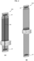
- First and second frame units 5, 6 are coupled in a separable manner to the respective coupling parts 3 of this drive unit 2 ( Fig. 2(B) ). These first and second frame units 5, 6 can be adjusted in a manner freely expandable and contractible in a direction coupling to their corresponding coupling parts 3 as illustrated in Fig. 2(A) and Fig. 2(B) . As a result, the wearable motion assistance device 1 can be made to perform motions by positioning the device at a desired joint site in a wearer's body by adjusting the length to the wearer's body site.
- each of the first and second frame units 5, 6 is provided with a connector CT of a specified structure and such connectors CT are electrically connected to each other by a freely-flexible extender cable EC through the inside of the frame.
- the drive unit 2 includes, as illustrated in Fig. 3 , a flat-shaped actuator 10 which is composed of, for example, a brushless DC motor, an actuator control unit 11 which performs drive control of the actuator 10, a speed reducer 12 which converts a rotational speed of a rotor for the actuator 10 into a specified speed reduction ratio and outputs it, and a flat-shaped operating unit 14 including a touch sensor 13.
- a flat-shaped actuator 10 which is composed of, for example, a brushless DC motor
- an actuator control unit 11 which performs drive control of the actuator 10
- a speed reducer 12 which converts a rotational speed of a rotor for the actuator 10 into a specified speed reduction ratio and outputs it
- a flat-shaped operating unit 14 including a touch sensor 13.
- An MCM Multi-Chip Module which is equipped with a CPU (Central Processing Unit), a memory, and so on is built in the actuator control unit 11.
- the operating unit 14 is composed of a touch panel 14A which configures a housing surface, and a power source button 14B at the center of the housing; and the content of operations on the touch panel 14A through a finger touch by the wearer is reflected, as a detection result of the touch sensor 13, in the actuator control unit 11 and the power is turned on or off as the power source button 14B is pressed.
- a main body of the speed reducer 12 and the actuator control unit 11 are housed in either one of the first or second housing 2A, 2B to be substantially flush with each other; the operating unit 14 is fixed to the main body of the speed reducer 12 so that the actuator 10 is placed between them; and an output axis of the speed reducer 12 is fixed to the other one of the first or second housing 2A, 2B.
- the drive unit 2 By making the drive unit 2 as small and thin as possible as described above, it becomes possible to make the wearer wear the device without giving them any physical burdens even in a state where the wearer is wearing clothes.
- Each coupling part 3 of the drive unit 2 has a rotary shaft RS in a direction vertical to the output axis of the speed reducer 12 and each of the first and second frame units 5, 6 is coupled in a freely rotatable manner about the rotary shaft RS of its corresponding coupling part 3.
- a connector having a specified structure (not shown in the drawing) is built in each coupling part 3 of the drive unit 2 and such corresponding connectors CT are made to engage with each other and be electrically connected when the first and second frame units 5, 6 are coupled to the drive unit 2.
- the wearable motion assistance device 1 makes it possible to mount the drive unit 2 and the first and second frame units 5, 6 in accordance with the shapes of the first and second body sites around the wearer's joint.
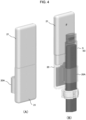
- the wearable motion assistance device 1 is designed as illustrated in Fig. 4(A) and Fig. 4(B) so that a communication unit 20 and a power source unit 21 can be integrated together and engage with the first and second frame units 5, 6 in a freely attachable/detachable manner.
- the communication unit 20 has a housing in a predetermined shape and is equipped with a communication function for transmitting and receiving data through connections via a near field communication method such as Bluetooth (registered trademark) or RF-ID.
- a fixed holder 20A for securing and retaining the first or second frame unit 5, 6 is formed to protrude from a lateral side of this housing and an engagement hole is formed at an upper end of the housing so that it can be freely attached to, or detached from and be integrated with the power source unit 21.
- the communication unit 20 which is integrated with the power source unit 21 is wired-connected with the drive unit 2 in its vicinity to enable supply of electric power to the drive unit 2 when engaging with the first or second frame unit 5, 6.
- a battery BT which is composed of a lithium ion secondary battery, and a battery driver BD are built in the power source unit 21, so that the power source unit 21 has a connector structure to enable an electric connection when engaging with the communication unit 20.
- the wearable motion assistance device 1 has a biosignal detection sensor 41 ( Fig. 6 ), which is composed of a contactless BES sensor for detecting a biosignal according to movements of a joint(s) which couple the wearer's first and second body sites together.
- the actuator control unit 11 can transmit a driving torque of the actuator 10 according to the movements of the wearer's joint as an assist force to the first and second body sites without giving any physical burdens or hindrances in daily life to the wearer by performing drive control of the actuator 10 for the drive unit 2 on the basis of a detection signal detected by the biosignal detection sensor 41.
- Fig. 6 is a block diagram illustrating an internal system configuration of the wearable motion assistance device 1.
- the actuator control unit 11 for the drive unit 2, as illustrated in Fig. 6 includes: an integrated control unit 34 configured from a voluntary control unit 30, an autonomous control unit 31, a phase specifying unit 32, and a gain control unit 33; an electric power amplification unit 35 for electric power control of the power source unit 21; an actuator driver 36 for drive control of the actuator 10; and a data storage unit 39 configured from a command signal database 37 and a reference parameter database 38.
- the actuator driver 36 in the drive unit 2 for imparting the assist force to the wearer is provided with a motion-and-posture sensor 40 which is composed of an angle sensor for detecting rotation angles of the first and second housings 10A, 10B as the wearer's joint rotate.
- the wearable motion assistance device 1 is also provided with a biosignal detection sensor 41 (which is not illustrated in Fig. 1 ) for detecting a signal (biosignal) including, for example, the wearer's bioelectric potential.
- the voluntary control unit 30 supplies, to the power amplification unit 29, a command signal (a control signal for voluntary control) according to the detection signal (biosignal) detected by the biosignal detection sensor 41.
- the voluntary control unit 30 generates a command signal by applying a specified command function f(t) or gain P to the biosignal detection sensor 41.
- This gain P may be a preset value or function and can be adjusted via the gain control unit 33 according to the content of operations of the operating unit 14.
- the drive unit 2 can select a method for controlling a driving torque (the size of the torque and a rotation angle) of the actuator 10 on the basis of angle data detected by the motion-and-posture sensor 40 provided in the actuator control unit 11.
- the angle data detected by the joint angle ( ⁇ ) detected by this motion-and-posture sensor 40 is input to the reference parameter database 38.
- the phase specifying unit 32 identifies a phase of the wearer's motion by comparing the rotation angle of the joint, which is detected by the motion-and-posture sensor 40, with the joint angle and load which are reference parameters stored in the reference parameter database 38.
- the autonomous control unit 31 when control data of the phase identified by the phase specifying unit 32 is obtained, the autonomous control unit 31 generates a command signal (a control signal of autonomous control) according to the control data of this phase and supplies, to the power amplification unit 29, a command signal for causing the actuator 10 for the drive unit 2 to generate this motive power.
- a command signal a control signal of autonomous control
- the gain adjusted by the aforementioned gain control unit 32 is input to the autonomous control unit 31 and the autonomous control unit 31 generates a command signal according to this gain and outputs the generated command signal to the electric power amplification unit 35.
- the electric power amplification unit 35 controls the size of the driving torque and the rotation angle by controlling an electric current for driving the actuator 10 for the drive unit 2 and imparts the driving power by the actuator 10 for the drive unit 2 to the joint which couples the wearer's first and second body sites together.
- the control signal for controlling the drive unit 2 is amplified by the electric power amplification unit 35 on the basis of the detection signal detected by the biosignal detection sensor 41, which is pasted with reference to the wearer's joint, and is then supplied to the actuator 10 and the driving power of the actuator 10 is transmitted as an assist force to the wearer's joint.
- the actuator control unit 11 for the drive unit 2 estimates the wearer's task and phase on the basis of the reference parameters stored in the data storage unit 39 and adjusts the drive control relative to the actuator 10 so as to generate the motive power according to that phase; and compensates for mechanical impedance (inertia, viscosity, and rigidity) of a control object of the entire system, which is composed of the entire device and the wearer, in accordance with viscoelasticity of the wearer and gravity of the control object of the entire system on the basis of the absolute angle, the rotation angle, the angular velocity, and the angular acceleration by the motion-and-posture sensor 40 and the driving torque obtained from the actuator driver 36.
- mechanical impedance in accordance with viscoelasticity of the wearer and gravity of the control object of the entire system on the basis of the absolute angle, the rotation angle, the angular velocity, and the angular acceleration by the motion-and-posture sensor 40 and the driving torque obtained from the actuator driver 36.
- Fig. 7(A) and Fig. 7(B) illustrate a wearable motion assistance device 50 according to a second embodiment and the wearable motion assistance device 50 has a drive unit 51 equipped with the actuator 10 ( Fig. 2 ), a communication unit 52 which is coupled in a freely movable manner to the drive unit 51, and a power source unit 53 which is attached to, and integrated with, the communication unit 52 in a freely detachable manner and is equipped with a battery for supplying the electric power to the actuator 10.
- This wearable motion assistance device 50 has substantially the same configuration as that of the aforementioned wearable motion assistance device 1 ( Fig. 1 ) according to the first embodiment, except for the shapes and structures of first and second housings 51A, 51B, which constitute the drive unit 51, and coupling parts 54.
- This drive unit 51 has: the first and second housings 51A, 51B in which the stator side and the rotor side of the actuator 10 are housed respectively and which engage with each other so that they rotate separately according to the driving of the actuator 10; and first and second coupling parts 54A, 54B which are formed to protrude respectively in opposite directions from the first and second housings 51A, 51B.
- the drive unit 51 has: the flat-shaped actuator 10 which is composed of, for example, a brushless DC motor; the actuator control unit 11 for performing drive control of the actuator 10; the speed reducer 12 which converts a rotational speed of a rotor for the actuator 10 into a specified speed reduction ratio and outputs it; and the flat-shaped operating unit 14 including the touch sensor 13.
- the flat-shaped actuator 10 which is composed of, for example, a brushless DC motor
- the actuator control unit 11 for performing drive control of the actuator 10
- the speed reducer 12 which converts a rotational speed of a rotor for the actuator 10 into a specified speed reduction ratio and outputs it
- the flat-shaped operating unit 14 including the touch sensor 13.
- a main body of the speed reducer 12 and the actuator control unit 11 are housed in either one of the first or second housing 51A, 51B to be substantially flush with each other; the operating unit 14 is fixed to the main body of the speed reducer 12 so that the actuator 10 is placed between them; and an output axis of the speed reducer 12 is fixed to the other one of the first or second housing 51A, 51B.
- the wearable motion assistance device 50 as described above, by making the drive unit 51 as small and thin as possible as described above, it becomes possible to make the wearer wear the device without giving them any physical burdens even in a state where the wearer is wearing clothes.
- each of the first and second coupling parts 54A, 54B for the drive unit 51 has a rotary shaft RS in a direction vertical to the output axis of the speed reducer 12 and the rotary shaft RS is coupled to the end of each first or second housing 51A, 51B in a freely rotatable manner.
- a connector having a specified structure is built in each of the first and second coupling parts 54A, 54B for the drive unit 51 and such corresponding connectors CT are made to engage with each other and be electrically connected when a frame unit (which is not illustrated in the drawing) and the communication unit 51 are coupled to the coupling parts, respectively.
- the wearable motion assistance device 50 makes it possible to mount the drive unit 51, the frame unit (which is not shown in the drawing), and the communication unit 52 in accordance with the shapes of the first and second body sites around the wearer's joint.
- the frame unit (which is not illustrated in Fig. 7 ) is coupled to the first coupling part 54A for the drive unit 51 in a separable manner and the communication unit 52 (including the integrated power source unit 53 which is integrated therewith) is coupled to the second coupling part 54B for the drive unit 51.
- the thickness of its housing is formed to be thinner than the thickness of the first and second housings 51A, 51B which configures the drive unit 51 and engage with each other. Consequently, with the wearable motion assistance device 50, by thinning all the frame unit (which is not illustrated in the drawing), the communication unit 52, and the power source unit 53 with reference to the thickness of the drive unit 51, it becomes possible to make the wearer to wear the device without giving them any physical burdens even in the state where the wearer is wearing clothes.
- the wearable motion assistance device 50 has the biosignal detection sensor 41 (which is not illustrated in the drawing) for detecting a biosignal according to movements of a joint which couples the wearer's first and second body sites together in the same manner as in the aforementioned first embodiment.
- the actuator control unit 11 perform drive control of the actuator 10 for the drive unit 51 on the basis of a detection signal detected by the biosignal detection sensor 41.
- the wearable motion assistance device 50 can transmit the driving torque of the actuator 10 according to the movements of the wearer's joint as an assist force to the first and second body sites without giving any physical burdens or hindrances in daily life to the wearer wearing clothes.
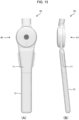
- Fig. 10(A) and Fig. 10(B) illustrate a wearable motion assistance device 60 showing a variation of an appearance design of the aforementioned wearable motion assistance device 50. It has the same internal configuration as that of the wearable motion assistance device 50 illustrated in Fig. 7(A) and Fig. 7(B) , except that part of a housing configuration of a drive unit 61 and a housing configuration of a communication unit 62 and a power source unit 63 are different.
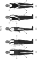
- This wearable motion assistance device 60 is designed to be capable of supporting motions of both hip joints of the wearer by attaching a suspension-belt-type corset 65 in a freely attachable/detachable manner to support the wearer's lower back part as illustrated in Fig. 11(A) to Fig. 11(E) .
- communication units 62 and power source units 63 in a pair of wearable motion assistance devices 60 are fixed and attached to both lower ends of the corset 65, respectively, and cuffs (which are not illustrated in the drawing) which are secured and fixed at the respective frame units 66 are made to enter contact with both thigh parts.
- the enter device is supported by a suspension belt in contact with both shoulders and a pair of drive units 61 are positioned on both sides of the hip joints, respectively.
- the wearer wears the corset 65 into which the wearable motion assistance devices 60 are incorporated, it is possible to generate the assist force to assist movements of the thigh parts relative to the lower back part when the wearer stands up from their bent state (a semi-crouching posture). Furthermore, regarding the wearer's motions other than the motion to stand up from the semi-crouching posture, it is also possible to perform, for example, a motion to lift a heavy article from the semi-crouching posture and a motion to assist moving from one place to another.
- FIG. 13(A) and Fig. 13(B) in which the same reference numerals as those in Fig. 7(A) and Fig. 7(B) are assigned to parts corresponding to those in Fig. 7(A) and Fig. 7(B) , illustrate a wearable motion assistance device 70 as another design.
- This wearable motion assistance device 70 has the same configuration as that of the aforementioned wearable motion assistance device 50, except that a communication unit 71 and a power source unit 72 have relatively slim housings.
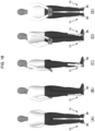
- the state of wearing the corset 62 into which this wearable motion assistance device 70 is incorporated is illustrated in Fig. 14(A) to Fig. 14(E) and Fig. 15(A) to Fig. 15(E) .
- This wearable motion assistance device 70 is designed, unlike the aforementioned wearable motion assistance device 50, so that a frame unit 66 is fixed and mounted at each of both lower ends of the corset 65 and cuffs (which are not illustrated in the drawing) secured and fixed to the communication unit 71 and the power source unit 72 which are integrated together are made to enter into contact with both thigh parts.
- a coupling part of a drive unit 61 for the wearable motion assistance device 70 is coupled to each of the pair of fixed holders 81A, 81B formed on the lower back belt 81 in the frame unit 80 and the cuff (which is not illustrated in the drawing) to which the communication unit 71 and the power source unit 72 are fixed and secured are made to enter contact with both the thigh parts, thereby positioning the pair of drive units 71 respectively on both sides of the hip joints.
- This device-wearing state is illustrated in Fig. 17(A) to Fig. 17(E) .
- a coupling part of the drive unit 71 for the wearable motion assistance device 70 is coupled to the fixed holder formed on each of the right and left shoes 85 and the cuff (which is not illustrated in the drawing) which is fixed and secured to the communication unit 71 and the power source unit 72 is made to enter into contact with an ankle part, thereby positioning the pair of drive units 71 to both sides of the ankles joints, respectively.
- a cuff 87 which is fixed and secured to a frame unit 86, around a wrist in a state where the drive unit 51 for the wearable motion assistance device 50 illustrated in Fig. 7 is positioned on the outside of the elbow, and by wrapping and retaining a cuff (which is not illustrated in the drawing) secured and fixed to the communication unit 52 and the power source unit 53, which are integrated together, around the upper arm.
- the wearable motion assistance devices 1, 50, 60, 70 can be combined together and be made to perform motions by positioning the devices at a desired joint site(s) in the wearer's body.
- a desired number of the wearable motion assistance devices 1 may be further combined with a pair of the wearable motion assistance devices 70 to which the aforementioned suspension-belt-type corset 65 is attached in a freely attachable/detachable manner.
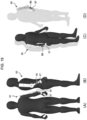
- Fig. 21(A) to Fig. 21(E) illustrate a state where practically the first and second wearable motion assistance devices 1, 50 ( Fig. 1 and Fig. 7 ) are combined together and mounted on the wearer. Consequently, it becomes possible to support the wearer's motions of both their hip joints, both their knee joints, and both their ankle joints.
- the communication unit 20 and the power source unit 21, which are integrated together in the wearable motion assistance device 60 according to the first embodiment, can be added and appended as necessary.
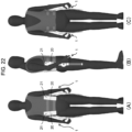
- the communication unit 20 and the power source unit 21 which are integrated together can perform contactless communication and power supply, it becomes possible to attach them at desired positions in the corset 65 (particularly, for example, on both sides of a lower-back back-face part which is a position that does not interfere with the wearer's motions) as illustrated in Fig. 22(A) to Fig. 22(C) . Consequently, the battery capacity can be substantially increased and the duration of motions can be extended.
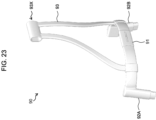
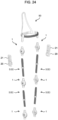
- an upper-body-type frame unit 90 as illustrated in Fig. 23 instead of the aforementioned frame unit 80 ( Fig. 16 ), it becomes possible to perform a motion to assist joint sites at the wearer's upper limbs and lower back and also perform a motion to assist joint sites in their lower limbs with reference to the lower back.
- This upper-body-type frame unit 90 is formed by integrating together: a lower back support 91 mounted on the wearer's lower back and designed to enter into contact with the wearer's back surface at their lower back; a pair of fixed holders 92A, 92B coupled to support a right end and a left end of the lower back support 91; and a back-part support 93 configured from a frame structure in a substantially isosceles triangle shape to support the wearer's back so that it extends upwards from its both sides between which a central part of the lower back support 91 is positioned.
- a coupling part 93X is formed in a horizonal direction at an upper end of this back-part support 93 so that it can be coupled to the coupling part 3 for the drive unit 2 in a freely attachable/detachable manner.
- one of the coupling parts 3 of the drive unit 2 for each wearable motion assistance device 1 is coupled to a pair of fixed holders 92A, 92B of the upper-body-type frame unit 90 to support the motions of the hip joint and one of the coupling parts 3 of the drive unit 2 for another wearable motion assistance device 1 is coupled to the other coupling part 3 of the above-mentioned drive unit 2 via the frame unit 5(6) to support the motions of the knee joint.
- one of the coupling parts 3 of the drive unit 2 for another wearable motion assistance device 1 is coupled to the other coupling part 3 of the drive unit 2 of the above-mentioned wearable motion assistance device 1 via the frame unit 5(6) to support the motions of the ankle joint.
- the fixed holder formed on the outside of the heel at the aforementioned shoe 85 is coupled to the other coupling part 3 of the drive unit 2 for this wearable motion assistance device 1.
- the frame unit 5(6) which couples together the drive unit 2 for supporting the motions of the hip joint and the drive unit 2 for supporting the motions of the knee joint and the frame unit 5(6) which couples together the drive unit 2 for supporting the motions of the knee joint and the drive unit 2 for supporting the motions of the ankle joint can adjust the length between the wearer's hip joint and the knee joint and the length between the knee joint and the ankle joint, respectively.
- the communication unit 20 and the power source unit 21 which are integrated together can be attached to the frame unit 5(6), which couples together the drive unit 2 for supporting the motions of the hip joint and the drive unit 2 for supporting the motions of the knee joint, in a freely attachable/detachable manner.
- the communication unit 20 and the power source unit 21 which are integrated together may be attached to a desired frame unit 5(6) as necessary, for example, when it is desired to enhance the supply of the electric power to the drive unit 2.
- a cuff(s) (which is not illustrated in the drawing) which is fixed and secured to a necessary site(s) of the frame unit 5(6) may be made to enter into contact with a body site(s) when supporting the motions of the wearer's hip joints, knee joints, and ankle joints, respectively.
- one of the coupling parts 3 of the drive unit for the wearable motion assistance device 1 is coupled to the coupling part 93X at the upper end of the back-part support 93 in the upper-body-type frame unit 90 to support motions of the shoulder joint in a frontal plane direction and one of the coupling parts 3 of the drive unit 2 for the wearable motion assistance device 1 is coupled to the other coupling part 3 of the above-mentioned drive unit 2 to support the motions of the shoulder joint in a sagittal plane direction.
- one of the coupling parts 3 of the drive unit 2 for the wearable motion assistance device 1 is coupled via the frame unit 5(6) to the other coupling part 3 of the drive unit 2 for the above-mentioned wearable motion assistance device 1 to support the motions of the elbow joint.
- the frame unit 5(6) to which a cuff to be wrapped around a wrist is secured and fixed is coupled to the other coupling part 3 of the drive unit 2 for this wearable motion assistance device 1.
- the frame unit 5(6) for coupling together the drive unit 2 for supporting the motions of the shoulder join in the frontal plane direction and the drive unit 2 for supporting the motions of the shoulder joint in the sagittal plane direction, and the frame unit 5(6) for coupling together the drive unit 2 for supporting the motions of the shoulder joint in the sagittal plane direction and the drive unit 2 for supporting the motions of the elbow joint can adjust the length of the wearer's shoulder width, the length between the shoulder joint and the elbow joint, and the length between the elbow joint and the wrist.
- the communication unit 20 and the power source unit 21 which are integrated together can be attached to the frame unit 5(6), which couples together the drive unit 2 for supporting the motions of the shoulder joint in the sagittal plane direction and the drive unit 2 for supporting the motions of the elbow joint, in a freely attachable/detachable manner.
- the aforementioned first and second embodiments have described the case where the frame unit having the shape and structure as illustrated in Fig. 23 is applied as the upper-body-type frame unit 90; however, the present invention is not limited to this example and those having various shapes and structures may be applied according to the content of the combination of the plurality of the wearable motion assistance devices 1, 50, 60, 70 by positioning the devices at a desired joint site(s) in the wearer's body.
- an upper-body-type frame unit 100 as illustrated in Fig. 29 is configured by integrating together a communication unit 101 and a power source unit 102 in predetermined shapes (no battery is illustrated in the drawing) in addition to the upper-body-type frame unit 90 illustrated in Fig. 23 described earlier.
- the upper-body-type frame unit 100 illustrated in Fig. 29 is formed by integrating together: a lower back support 105 mounted on the wearer's lower back and designed to enter into contact with the wearer's back surface at their lower back; a pair of fixed holders 106A, 106B coupled to support a right end and a left end of the lower back support 105; a power source unit 102 in which a central part of the lower back support 105 is provided in its upper side; a communication unit 101 provided in an upper side of the power source unit 102; and a back support frame 107 for supporting the wearer's back so that it extends upwards from the inside of the communication unit 101.
- This upper-body-type frame unit 100 is very effective when, for example, the body size of the wearer is very small like that of an infant or a child.
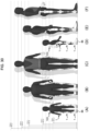
- the body size of the wearer is very small as illustrated in Fig. 30(A) to Fig. 30(F) (Fig. 30(A) and Fig. 30(D) )
- the combination of the plurality of the wearable motion assistance devices 1 cannot be applied unless the length of the frame unit 5(6) coupled to the drive unit 2 is made much shorter than that for an adult.
- the communication unit and the power source unit which are integrated together cannot be attached directly to the frame unit 5(6); and, therefore, by applying the upper-body-type frame unit 100, even the wearer whose body size is small can operate the device sufficiently for practical purposes by positioning the device at a desired joint site(s).
Landscapes
- Health & Medical Sciences (AREA)
- Epidemiology (AREA)
- Pain & Pain Management (AREA)
- Physical Education & Sports Medicine (AREA)
- Rehabilitation Therapy (AREA)
- Life Sciences & Earth Sciences (AREA)
- Animal Behavior & Ethology (AREA)
- General Health & Medical Sciences (AREA)
- Public Health (AREA)
- Veterinary Medicine (AREA)
- Engineering & Computer Science (AREA)
- Robotics (AREA)
- Mechanical Engineering (AREA)
- Manipulator (AREA)
- Rehabilitation Tools (AREA)
- Prostheses (AREA)
Description
- The present invention is suited for application to a wearable motion assistance device for assisting motions of, for example, a physically handicapped person who lost their muscular strength or an elderly person whose muscular strength has weakened, or for performing the motions on their behalf.
- In Japan, we are facing super-aging society where an aging rate continues increasing regardless of the tendency of a reduction of total population in Japan; and the number of people who receive certifications of needed nursing care or needed supports as they age is increasing every year more rapidly than an increase in the number of elderly people.
- Since an elderly person's physical functions decrease and their walking function deteriorates as they age, a fall-down risk increases. When the elderly person falls down, they may not die, but external injuries, particularly bone fractures, caused by the falling down will have a significant impact on the physical functions and cause a serious problem which may lead to a bedridden state or a state requiring nursing care.
- It has been conventionally believed that maintenance and enhancement of the physical functions by physical exercise are effective in preventing the falling down; and it is reported that balance training including walking and augmentation of the muscular strength can have not only the fall-down prevention effect, but also the effect of reducing bone fractures caused by the falling down.
- However, regarding walking of an elderly person, shuffling gait, a stride length reduction and its resultant reduction in a walking speed, a forward-bent walking posture, and so on tend to easily appear as characteristic gait due to lowering of the muscular strength and flexibility of their body trunk and lower limbs and they can easily stumble over, for example, even a slight difference in level. Therefore, it is believed to be important to realize a proper walking posture and reduce the fall-down risk by assisting the diminished physical functions of the elderly person.
- In recent years, there have been a wide spread of various power assist devices for assisting motions of physically handicapped persons who lost their muscular strength or elderly persons whose muscular strength diminished, or for performing the motions on their behalf. As these power assist devices, for example, there has been proposed a wearable motion assistance device capable of controlling and assisting physical exercises on the basis of a bioelectric potential associated with voluntary muscular activities according to a wearer's intention (see, for example, PTL 1).
-
PTL 2 discloses a wearable movement assisting device including a drive unit with a motor, a first transmission member, and a second transmission member. The motor is disposed at the side of a left knee joint of the wearer. The first transmitting member and second transmitting member are fastened to the left thigh and thin of the wearer through fastening members. A control signal for controlling the motor is generated on the basis of a signal detected by biological signal detection sensors. -
PTL 3 discloses a method for controlling movement using an active powered device including an actuator, joint position sensor, muscle stress sensor, and control system. The device is designed for operation in several modes to provide either assistance or resistance to a muscle for the purpose of enhancing mobility, preventing injury, or building muscle strength. - PTL 4 discloses a thigh frame and a lower thigh frame that can be relatively moved in a fore and aft direction by meshing a thigh side gear arranged at the lower end of the thigh frame and a lower thigh side gear arranged at the upper end of the lower thigh frame, securing the housing of a knee joint actuator arranged coaxially with the axial line of the thigh side gear to the thigh frame, and moving the lower thigh side gear around the axial line by the rotor of the knee joint actuator and revolving it around the thigh side gear.
-
- PTL 1:
Japanese Patent Application Laid-Open (Kokai) Publication No. 2005-253650 - PTL 2:
JP 2014 054273 A - PTL 3:
US 2004/102723 A1 - PTL 4:
JP 2006 115971 A - Meanwhile, as some elderly persons do not want to use a cane, it seems that there seem to exist many elderly persons who have strong psychological resistance to wearing the wearable motion assistance device. So, it is necessary to reduce the weight of the entire device in order to reduce the elderly person's physical burdens.
- Also, assuming a case where an elderly person sits on a chair or ride a vehicle in order for them to go out or spend daily life, it is important to downsize an amount of protrusions from their body not only on their lateral sides, but on their back side. Therefore, it is desirable that the wearable motion assistance device should be made as small and thin as possible and be designed in a clothing form close to everyday clothes.
- Furthermore, it is highly desirable that the wearable motion assistance device should be made to perform motions corresponding to various joint sites of the wearer's body, not only the wearer's walking motions, but also their upper limb motions and lower back part motions.
- The present invention was devised in consideration of the above-described circumstances and proposes a wearable motion assistance device which is intended to achieve relatively light weight, downsizing, and thinning and can be made to perform motions by positioning the device at a desired joint site(s) of the wearer's body.
- In order to solve the above-described problems, there is provided according to the present invention a wearable motion assistance device as defined in
claim 1. - As a result, with the wearable motion assistance device in the state where the drive unit is located on a lateral side of a joint of the wearer wearing clothes and the first and second frame units are fixed and retained respectively corresponding to the wearer's first and second body sites, a driving torque of the actuator according to motions of the wearer's joint can be transmitted as an assist force to the first and second body sites without giving any physical burdens or hindrances in daily life to the wearer.
- Moreover, the present invention is designed so that the physical quantity detector detects an absolute angle, a rotation angle, an angular velocity, angular acceleration, and a driving torque between the first and second housings as the physical quantity regarding the rotary motion between the first and second housings.
- Furthermore, the present invention is designed so that: the first and second coupling parts of the drive unit have rotary shafts along a direction vertical to an output axis of the speed reducer; and the frame unit and the communication unit are coupled to the drive unit so that they can freely rotate about the rotary shafts of the first and second coupling parts.
- As a result, with the wearable motion assistance device, the drive unit, the frame unit, and the communication unit can be mounted on the wearer in accordance with the shapes of the first and second body sites around the wearer's joint.
- Furthermore, the present invention is designed so that the drive unit has a flat-shaped actuator, an actuator driver which performs drive control of the actuator, a speed reducer which converts a rotational speed of a rotor for the actuator into a specified speed reduction ratio and outputs the converted rotational speed, and a flat-shaped operating unit including a touch sensor; and a main body of the speed reducer and the actuator driver are housed in either one of the first or second housing to be substantially flush with each other and the operating unit is fixed to the main body of the speed reducer so that the actuator is located between the main body and the operating unit; and an output axis of the speed reducer is fixed to the other one of the first or second housing.
- Consequently, by making the drive unit for the wearable motion assistance device as small and thin as possible, it becomes possible to make the wearer wear the wearable motion assistance device without giving them any physical burdens even in the state where the wearer is wearing clothes.
- Furthermore, the present invention is designed so that each of the first and second frame units and the power source unit is formed so that a thickness of its housing is thinner than a thickness of the first and second housings which constitute the drive unit and engage with each other.
- Consequently, by thinning all the frame unit, the communication unit, and the power source unit for the wearable motion assistance device with reference to the thick ness of the drive unit, it becomes possible to make the wearer wear the wearable motion assistance device without giving them any physical burdens even in the state where the wearer is wearing clothes.
- Furthermore, the present invention is designed so that either one or both of the first and second frame units can be adjusted in a freely expandable and contractible manner in a direction of coupling to the coupling part. As a result, by adjusting the length of the wearable motion assistance device in accordance with the wearer's body site, it is possible to make the wearable motion assistance device perform motions by positioning the device at a desired joint site in the wearer's body.
- Furthermore, there is also provided according to the present invention a wearable motion assistance device as defined in
claim 6. - As a result, with the wearable motion assistance device in the state where the drive unit is located on a lateral side of a joint of the wearer wearing clothes and the communication unit and the frame unit are fixed and retained respectively corresponding to the wearer's first and second body sites, a driving torque of the actuator according to motions of the wearer's joint can be transmitted as an assist force to the first and second body sites without giving any physical burdens or hindrances in daily life to the wearer.
- According to the present invention as described above, it is possible to realize the wearable motion assistance device which can reduce physical loads on the wearer, who is wearing clothes, as much as possible and can be made to perform motions by positioning the device at a desired joint site(s) in the wear's body.
-
-
Fig. 1 is an external configuration diagram of a wearable motion assistance device according to a first embodiment; -
Fig. 2 is an external configuration diagram illustrating first and second frame units shown inFig. 1 ; -
Fig. 3 is an exploded view illustrating the configuration of a drive unit for the wearable motion assistance device shown inFig. 1 ; -
Fig. 4 is an external configuration diagram illustrating a communication unit and a power source unit which are integrated together; -
Fig. 5 is a transparent diagram illustrating an internal configuration of the communication unit and the power source unit which are shown inFig. 4 ; -
Fig. 6 is a block diagram illustrating an internal system configuration of the wearable motion assistance device; -
Fig. 7 is an external configuration diagram of a wearable motion assistance device according to a second embodiment; -
Fig. 8 is an exploded view illustrating the configuration of a drive unit for the wearable motion assistance device shown inFig. 7 ; -
Fig. 9 is a transparent diagram illustrating an internal configuration of a coupling part of the drive unit shown inFig. 8 ; -
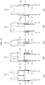
Fig. 10 is an external configuration diagram illustrating a variation of an appearance design of the wearable motion assistance device according to the second embodiment; -
Fig. 11 is a schematic diagram illustrating a combination of the wearable motion assistance device shown inFig. 7 and a suspension-belt-type corset; -
Fig. 12 is a schematic diagram illustrating a state of a wearer wearing a device composed of the combination inFig. 7 ; -
Fig. 13 is an external configuration diagram illustrating a variation of an appearance design of the wearable motion assistance device according to the second embodiment; -
Fig. 14 is a schematic diagram illustrating a combination of the wearable motion assistance device shown inFig. 13 and a suspension-belt-type corset; -
Fig. 15 is a schematic diagram illustrating a state of the wearer wearing a device composed of the combination inFig. 13 ; -
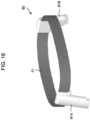
Fig. 16 is an external configuration diagram illustrating a variation of a frame unit (a lower back belt) for the wearable motion assistance device according to the second embodiment; -
Fig. 17 is a schematic diagram illustrating a state of the wearer wearing a device including the frame unit inFig. 16 ; -
Fig. 18 is a schematic diagram illustrating a state of the wearer wearing the wearable motion assistance device shown inFig. 13 at their ankles; -
Fig. 19 is a schematic diagram illustrating a state of the wearer wearing the wearable motion assistance device shown inFig. 7 on their upper arm; -
Fig. 20 is a schematic diagram illustrating a combination of the wearable motion assistance devices shown inFig. 1 andFig. 7 and a suspension-belt-type corset; -
Fig. 21 is a schematic diagram illustrating a state of the wearer wearing a device composed of the combination inFig. 20 ; -
Fig. 22 is an external configuration diagram illustrating a state where the communication unit and the power source unit which are integrated together are added; -
Fig. 23 is an external configuration diagram illustrating an upper-body-type frame unit for a wearable motion assistance device according to another embodiment; -
Fig. 24 is an exploded configuration diagram illustrating a combination of the wearable motion assistance devices according to the first and second embodiments; -
Fig. 25 is a schematic diagram illustrating a state of the wearer wearing a device composed of the combination shown inFig. 24 ; -
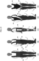
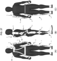
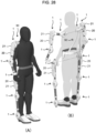
Fig. 26 is a schematic diagram illustrating an application example of the combination of the wearable motion assistance devices according to the first and second embodiments; -
Fig. 27 is a schematic diagram illustrating an application example of the combination of the wearable motion assistance devices according to the first and second embodiments; -
Fig. 28 is a schematic diagram illustrating an application example of the combination of the wearable motion assistance devices according to the first and second embodiments; -
Fig. 29 is an external configuration diagram illustrating a variation of an upper-body-type frame unit for a wearable motion assistance device according to another embodiment; and -
Fig. 30 is a schematic diagram illustrating an application example of a combination of a plurality of wearable motion assistance devices when the wearer's body size is very small. - An embodiment of the present invention will be described below in detail with reference to the drawings.
-
Fig. 1(A) and Fig. 1(B) illustrate a wearablemotion assistance device 1 according to a first embodiment. With the wearablemotion assistance device 1, adrive unit 2 has first andsecond housings Fig. 3 ) are respectively housed and which engage with each other so that they rotate separately according to driving of theactuator 10; and coupling parts of the same structure are formed to protrude from the first andsecond housings - First and
second frame units respective coupling parts 3 of this drive unit 2 (Fig. 2(B) ). These first andsecond frame units corresponding coupling parts 3 as illustrated inFig. 2(A) and Fig. 2(B) . As a result, the wearablemotion assistance device 1 can be made to perform motions by positioning the device at a desired joint site in a wearer's body by adjusting the length to the wearer's body site. - Furthermore, one end and the other end of each of the first and
second frame units - The
drive unit 2 includes, as illustrated inFig. 3 , a flat-shapedactuator 10 which is composed of, for example, a brushless DC motor, anactuator control unit 11 which performs drive control of theactuator 10, aspeed reducer 12 which converts a rotational speed of a rotor for theactuator 10 into a specified speed reduction ratio and outputs it, and a flat-shapedoperating unit 14 including atouch sensor 13. - An MCM (Multi-Chip Module) which is equipped with a CPU (Central Processing Unit), a memory, and so on is built in the
actuator control unit 11. - The operating
unit 14 is composed of atouch panel 14A which configures a housing surface, and apower source button 14B at the center of the housing; and the content of operations on thetouch panel 14A through a finger touch by the wearer is reflected, as a detection result of thetouch sensor 13, in theactuator control unit 11 and the power is turned on or off as thepower source button 14B is pressed. - In the
drive unit 2, a main body of thespeed reducer 12 and theactuator control unit 11 are housed in either one of the first orsecond housing unit 14 is fixed to the main body of thespeed reducer 12 so that theactuator 10 is placed between them; and an output axis of thespeed reducer 12 is fixed to the other one of the first orsecond housing - By making the
drive unit 2 as small and thin as possible as described above, it becomes possible to make the wearer wear the device without giving them any physical burdens even in a state where the wearer is wearing clothes. - Each
coupling part 3 of thedrive unit 2 has a rotary shaft RS in a direction vertical to the output axis of thespeed reducer 12 and each of the first andsecond frame units corresponding coupling part 3. - Moreover, a connector having a specified structure (not shown in the drawing) is built in each
coupling part 3 of thedrive unit 2 and such corresponding connectors CT are made to engage with each other and be electrically connected when the first andsecond frame units drive unit 2. - Consequently, the wearable
motion assistance device 1 makes it possible to mount thedrive unit 2 and the first andsecond frame units - The wearable
motion assistance device 1 is designed as illustrated inFig. 4(A) and Fig. 4(B) so that acommunication unit 20 and apower source unit 21 can be integrated together and engage with the first andsecond frame units - Specifically, as illustrated in
Fig. 5(A) to Fig. 5(C) , thecommunication unit 20 has a housing in a predetermined shape and is equipped with a communication function for transmitting and receiving data through connections via a near field communication method such as Bluetooth (registered trademark) or RF-ID. A fixedholder 20A for securing and retaining the first orsecond frame unit power source unit 21. - The
communication unit 20 which is integrated with thepower source unit 21 is wired-connected with thedrive unit 2 in its vicinity to enable supply of electric power to thedrive unit 2 when engaging with the first orsecond frame unit power source unit 21, so that thepower source unit 21 has a connector structure to enable an electric connection when engaging with thecommunication unit 20. - Furthermore, the wearable
motion assistance device 1 has a biosignal detection sensor 41 (Fig. 6 ), which is composed of a contactless BES sensor for detecting a biosignal according to movements of a joint(s) which couple the wearer's first and second body sites together. - With the wearable
motion assistance device 1 described above, in a state where thedrive unit 2 is located on a lateral side of a joint of the wearer wearing clothes and the first andsecond frame units actuator control unit 11 can transmit a driving torque of theactuator 10 according to the movements of the wearer's joint as an assist force to the first and second body sites without giving any physical burdens or hindrances in daily life to the wearer by performing drive control of theactuator 10 for thedrive unit 2 on the basis of a detection signal detected by thebiosignal detection sensor 41. -
Fig. 6 is a block diagram illustrating an internal system configuration of the wearablemotion assistance device 1. Theactuator control unit 11 for thedrive unit 2, as illustrated inFig. 6 , includes: anintegrated control unit 34 configured from avoluntary control unit 30, anautonomous control unit 31, aphase specifying unit 32, and again control unit 33; an electricpower amplification unit 35 for electric power control of thepower source unit 21; anactuator driver 36 for drive control of theactuator 10; and adata storage unit 39 configured from acommand signal database 37 and areference parameter database 38. - With this wearable
motion assistance device 1, theactuator driver 36 in thedrive unit 2 for imparting the assist force to the wearer is provided with a motion-and-posture sensor 40 which is composed of an angle sensor for detecting rotation angles of the first and second housings 10A, 10B as the wearer's joint rotate. Also, the wearablemotion assistance device 1 is also provided with a biosignal detection sensor 41 (which is not illustrated inFig. 1 ) for detecting a signal (biosignal) including, for example, the wearer's bioelectric potential. - In the
integrated control unit 34, thevoluntary control unit 30 supplies, to the power amplification unit 29, a command signal (a control signal for voluntary control) according to the detection signal (biosignal) detected by thebiosignal detection sensor 41. Thevoluntary control unit 30 generates a command signal by applying a specified command function f(t) or gain P to thebiosignal detection sensor 41. This gain P may be a preset value or function and can be adjusted via thegain control unit 33 according to the content of operations of the operatingunit 14. - Moreover, the
drive unit 2 can select a method for controlling a driving torque (the size of the torque and a rotation angle) of theactuator 10 on the basis of angle data detected by the motion-and-posture sensor 40 provided in theactuator control unit 11. - The angle data detected by the joint angle (θ) detected by this motion-and-
posture sensor 40 is input to thereference parameter database 38. Thephase specifying unit 32 identifies a phase of the wearer's motion by comparing the rotation angle of the joint, which is detected by the motion-and-posture sensor 40, with the joint angle and load which are reference parameters stored in thereference parameter database 38. - Then, when control data of the phase identified by the
phase specifying unit 32 is obtained, theautonomous control unit 31 generates a command signal (a control signal of autonomous control) according to the control data of this phase and supplies, to the power amplification unit 29, a command signal for causing theactuator 10 for thedrive unit 2 to generate this motive power. - Furthermore, the gain adjusted by the aforementioned
gain control unit 32 is input to theautonomous control unit 31 and theautonomous control unit 31 generates a command signal according to this gain and outputs the generated command signal to the electricpower amplification unit 35. The electricpower amplification unit 35 controls the size of the driving torque and the rotation angle by controlling an electric current for driving theactuator 10 for thedrive unit 2 and imparts the driving power by theactuator 10 for thedrive unit 2 to the joint which couples the wearer's first and second body sites together. - With the wearable
motion assistance device 1 described above, the control signal for controlling thedrive unit 2 is amplified by the electricpower amplification unit 35 on the basis of the detection signal detected by thebiosignal detection sensor 41, which is pasted with reference to the wearer's joint, and is then supplied to theactuator 10 and the driving power of theactuator 10 is transmitted as an assist force to the wearer's joint. - Furthermore, with the wearable
motion assistance device 1, theactuator control unit 11 for the drive unit 2: estimates the wearer's task and phase on the basis of the reference parameters stored in thedata storage unit 39 and adjusts the drive control relative to theactuator 10 so as to generate the motive power according to that phase; and compensates for mechanical impedance (inertia, viscosity, and rigidity) of a control object of the entire system, which is composed of the entire device and the wearer, in accordance with viscoelasticity of the wearer and gravity of the control object of the entire system on the basis of the absolute angle, the rotation angle, the angular velocity, and the angular acceleration by the motion-and-posture sensor 40 and the driving torque obtained from theactuator driver 36. - Incidentally, a compensation method for the above-mentioned mechanical impedance of the control object of the entire system in accordance with the viscoelasticity of the wearer is described in detail in a Japanese Patent Laid-Open Publication by the inventor of the present application (
Japanese Patent Republication No. 2018-92325 4178187 -
Fig. 7(A) and Fig. 7(B) illustrate a wearablemotion assistance device 50 according to a second embodiment and the wearablemotion assistance device 50 has adrive unit 51 equipped with the actuator 10 (Fig. 2 ), acommunication unit 52 which is coupled in a freely movable manner to thedrive unit 51, and apower source unit 53 which is attached to, and integrated with, thecommunication unit 52 in a freely detachable manner and is equipped with a battery for supplying the electric power to theactuator 10. - This wearable
motion assistance device 50 has substantially the same configuration as that of the aforementioned wearable motion assistance device 1 (Fig. 1 ) according to the first embodiment, except for the shapes and structures of first andsecond housings drive unit 51, and coupling parts 54. - This
drive unit 51 has: the first andsecond housings actuator 10 are housed respectively and which engage with each other so that they rotate separately according to the driving of theactuator 10; and first andsecond coupling parts second housings - Furthermore, specifically speaking, as illustrated in
Fig. 8 in which the same reference numerals as those inFig. 3 are assigned to parts corresponding to those inFig. 3 , thedrive unit 51 has: the flat-shapedactuator 10 which is composed of, for example, a brushless DC motor; theactuator control unit 11 for performing drive control of theactuator 10; thespeed reducer 12 which converts a rotational speed of a rotor for theactuator 10 into a specified speed reduction ratio and outputs it; and the flat-shapedoperating unit 14 including thetouch sensor 13. - In the
drive unit 51, a main body of thespeed reducer 12 and theactuator control unit 11 are housed in either one of the first orsecond housing unit 14 is fixed to the main body of thespeed reducer 12 so that theactuator 10 is placed between them; and an output axis of thespeed reducer 12 is fixed to the other one of the first orsecond housing - With the wearable
motion assistance device 50 as described above, by making thedrive unit 51 as small and thin as possible as described above, it becomes possible to make the wearer wear the device without giving them any physical burdens even in a state where the wearer is wearing clothes. - Referring to
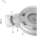
Fig. 9 , each of the first andsecond coupling parts drive unit 51 has a rotary shaft RS in a direction vertical to the output axis of thespeed reducer 12 and the rotary shaft RS is coupled to the end of each first orsecond housing - Furthermore, a connector having a specified structure is built in each of the first and
second coupling parts drive unit 51 and such corresponding connectors CT are made to engage with each other and be electrically connected when a frame unit (which is not illustrated in the drawing) and thecommunication unit 51 are coupled to the coupling parts, respectively. - Consequently, the wearable
motion assistance device 50 makes it possible to mount thedrive unit 51, the frame unit (which is not shown in the drawing), and thecommunication unit 52 in accordance with the shapes of the first and second body sites around the wearer's joint. - Referring to
Fig. 7 , in the wearablemotion assistance device 50, the frame unit (which is not illustrated inFig. 7 ) is coupled to thefirst coupling part 54A for thedrive unit 51 in a separable manner and the communication unit 52 (including the integratedpower source unit 53 which is integrated therewith) is coupled to thesecond coupling part 54B for thedrive unit 51. - Regarding each of the frame unit (which is not illustrated in the drawing), the
communication unit 52, and thepower source unit 53, the thickness of its housing is formed to be thinner than the thickness of the first andsecond housings drive unit 51 and engage with each other. Consequently, with the wearablemotion assistance device 50, by thinning all the frame unit (which is not illustrated in the drawing), thecommunication unit 52, and thepower source unit 53 with reference to the thickness of thedrive unit 51, it becomes possible to make the wearer to wear the device without giving them any physical burdens even in the state where the wearer is wearing clothes. - Furthermore, the wearable
motion assistance device 50 has the biosignal detection sensor 41 (which is not illustrated in the drawing) for detecting a biosignal according to movements of a joint which couples the wearer's first and second body sites together in the same manner as in the aforementioned first embodiment. - With this wearable
motion assistance device 50 in a state where thedrive unit 51 is located on a lateral side of the wearer's joint and thecommunication unit 52 and the frame unit (which is not illustrated in the drawing) are fixed and retained respectively corresponding to the wearer's first and second body sites, theactuator control unit 11 perform drive control of theactuator 10 for thedrive unit 51 on the basis of a detection signal detected by thebiosignal detection sensor 41. - As a result, the wearable
motion assistance device 50 can transmit the driving torque of theactuator 10 according to the movements of the wearer's joint as an assist force to the first and second body sites without giving any physical burdens or hindrances in daily life to the wearer wearing clothes. -
Fig. 10(A) and Fig. 10(B) illustrate a wearablemotion assistance device 60 showing a variation of an appearance design of the aforementioned wearablemotion assistance device 50. It has the same internal configuration as that of the wearablemotion assistance device 50 illustrated inFig. 7(A) and Fig. 7(B) , except that part of a housing configuration of adrive unit 61 and a housing configuration of acommunication unit 62 and apower source unit 63 are different. - This wearable
motion assistance device 60 is designed to be capable of supporting motions of both hip joints of the wearer by attaching a suspension-belt-type corset 65 in a freely attachable/detachable manner to support the wearer's lower back part as illustrated inFig. 11(A) to Fig. 11(E) . - Specifically speaking, as illustrated in
Fig. 11(A) to Fig. 11(E) andFig. 12(A) to Fig. 12(E) ,communication units 62 andpower source units 63 in a pair of wearablemotion assistance devices 60 are fixed and attached to both lower ends of thecorset 65, respectively, and cuffs (which are not illustrated in the drawing) which are secured and fixed at therespective frame units 66 are made to enter contact with both thigh parts. The enter device is supported by a suspension belt in contact with both shoulders and a pair ofdrive units 61 are positioned on both sides of the hip joints, respectively. - Consequently, as the wearer wears the
corset 65 into which the wearablemotion assistance devices 60 are incorporated, it is possible to generate the assist force to assist movements of the thigh parts relative to the lower back part when the wearer stands up from their bent state (a semi-crouching posture). Furthermore, regarding the wearer's motions other than the motion to stand up from the semi-crouching posture, it is also possible to perform, for example, a motion to lift a heavy article from the semi-crouching posture and a motion to assist moving from one place to another. - Furthermore,
Fig. 13(A) and Fig. 13(B) , in which the same reference numerals as those inFig. 7(A) and Fig. 7(B) are assigned to parts corresponding to those inFig. 7(A) and Fig. 7(B) , illustrate a wearablemotion assistance device 70 as another design. This wearablemotion assistance device 70 has the same configuration as that of the aforementioned wearablemotion assistance device 50, except that acommunication unit 71 and apower source unit 72 have relatively slim housings. The state of wearing thecorset 62 into which this wearablemotion assistance device 70 is incorporated is illustrated inFig. 14(A) to Fig. 14(E) andFig. 15(A) to Fig. 15(E) . - This wearable
motion assistance device 70 is designed, unlike the aforementioned wearablemotion assistance device 50, so that aframe unit 66 is fixed and mounted at each of both lower ends of thecorset 65 and cuffs (which are not illustrated in the drawing) secured and fixed to thecommunication unit 71 and thepower source unit 72 which are integrated together are made to enter into contact with both thigh parts. - Furthermore, as another type of device wearing method, it is also possible to support motions of both the hip joints of the wearer by combining a pair of wearable motion assistance devices 70 (50, 60) by using a
lower back belt 81, on which a pair of fixedholders frame unit 80 as illustrated inFig. 16 . - Specifically speaking, a coupling part of a
drive unit 61 for the wearablemotion assistance device 70 is coupled to each of the pair of fixedholders lower back belt 81 in theframe unit 80 and the cuff (which is not illustrated in the drawing) to which thecommunication unit 71 and thepower source unit 72 are fixed and secured are made to enter contact with both the thigh parts, thereby positioning the pair ofdrive units 71 respectively on both sides of the hip joints. This device-wearing state is illustrated inFig. 17(A) to Fig. 17(E) . - Furthermore, as another type of device wearing method, it is also possible to support motions of the wearer's ankle joint(s) by using a shoe(s) 85 on which a fixed holder (which is not illustrated in the drawing) is formed on the outside of a heel as illustrated in
Fig. 18(A) to Fig. 18(E) . Specifically speaking, a coupling part of thedrive unit 71 for the wearablemotion assistance device 70 is coupled to the fixed holder formed on each of the right and leftshoes 85 and the cuff (which is not illustrated in the drawing) which is fixed and secured to thecommunication unit 71 and thepower source unit 72 is made to enter into contact with an ankle part, thereby positioning the pair ofdrive units 71 to both sides of the ankles joints, respectively. - Furthermore, as another type of device wearing method, it is also possible to support motions of the wear's elbow joint, as illustrated in
Fig. 19(A) to Fig. 19(D) , by wrapping and retaining acuff 87, which is fixed and secured to aframe unit 86, around a wrist in a state where thedrive unit 51 for the wearablemotion assistance device 50 illustrated inFig. 7 is positioned on the outside of the elbow, and by wrapping and retaining a cuff (which is not illustrated in the drawing) secured and fixed to thecommunication unit 52 and thepower source unit 53, which are integrated together, around the upper arm. - The wearable
motion assistance devices - For example, as illustrated in
Fig. 20(A) to Fig. 20(E) , in which the same reference numerals as those inFig. 11(A) to Fig. 11(E) are assigned to parts corresponding to those inFig. 11(A) to Fig. 11(E) , a desired number of the wearablemotion assistance devices 1 may be further combined with a pair of the wearablemotion assistance devices 70 to which the aforementioned suspension-belt-type corset 65 is attached in a freely attachable/detachable manner. -
Fig. 21(A) to Fig. 21(E) illustrate a state where practically the first and second wearablemotion assistance devices 1, 50 (Fig. 1 andFig. 7 ) are combined together and mounted on the wearer. Consequently, it becomes possible to support the wearer's motions of both their hip joints, both their knee joints, and both their ankle joints. - Moreover, the
communication unit 20 and thepower source unit 21, which are integrated together in the wearablemotion assistance device 60 according to the first embodiment, can be added and appended as necessary. For example, since thecommunication unit 20 and thepower source unit 21 which are integrated together can perform contactless communication and power supply, it becomes possible to attach them at desired positions in the corset 65 (particularly, for example, on both sides of a lower-back back-face part which is a position that does not interfere with the wearer's motions) as illustrated inFig. 22(A) to Fig. 22(C) . Consequently, the battery capacity can be substantially increased and the duration of motions can be extended. - For example, by applying an upper-body-
type frame unit 90 as illustrated inFig. 23 instead of the aforementioned frame unit 80 (Fig. 16 ), it becomes possible to perform a motion to assist joint sites at the wearer's upper limbs and lower back and also perform a motion to assist joint sites in their lower limbs with reference to the lower back. - This upper-body-
type frame unit 90 is formed by integrating together: alower back support 91 mounted on the wearer's lower back and designed to enter into contact with the wearer's back surface at their lower back; a pair of fixedholders lower back support 91; and a back-part support 93 configured from a frame structure in a substantially isosceles triangle shape to support the wearer's back so that it extends upwards from its both sides between which a central part of thelower back support 91 is positioned. Acoupling part 93X is formed in a horizonal direction at an upper end of this back-part support 93 so that it can be coupled to thecoupling part 3 for thedrive unit 2 in a freely attachable/detachable manner. - It becomes possible to support motions of joints at the wearer's lower back part and lower limbs by combining a plurality of wearable
motion assistance devices 1 including this upper-body-type frame unit 90. For example, as illustrated inFig. 24 andFig. 25(A) to Fig. 25(C) , one of thecoupling parts 3 of thedrive unit 2 for each wearablemotion assistance device 1 is coupled to a pair of fixedholders type frame unit 90 to support the motions of the hip joint and one of thecoupling parts 3 of thedrive unit 2 for another wearablemotion assistance device 1 is coupled to theother coupling part 3 of the above-mentioneddrive unit 2 via the frame unit 5(6) to support the motions of the knee joint. - Furthermore, one of the
coupling parts 3 of thedrive unit 2 for another wearablemotion assistance device 1 is coupled to theother coupling part 3 of thedrive unit 2 of the above-mentioned wearablemotion assistance device 1 via the frame unit 5(6) to support the motions of the ankle joint. The fixed holder formed on the outside of the heel at theaforementioned shoe 85 is coupled to theother coupling part 3 of thedrive unit 2 for this wearablemotion assistance device 1. - Under this circumstance, the frame unit 5(6) which couples together the
drive unit 2 for supporting the motions of the hip joint and thedrive unit 2 for supporting the motions of the knee joint, and the frame unit 5(6) which couples together thedrive unit 2 for supporting the motions of the knee joint and thedrive unit 2 for supporting the motions of the ankle joint can adjust the length between the wearer's hip joint and the knee joint and the length between the knee joint and the ankle joint, respectively. - Moreover, the
communication unit 20 and thepower source unit 21 which are integrated together can be attached to the frame unit 5(6), which couples together thedrive unit 2 for supporting the motions of the hip joint and thedrive unit 2 for supporting the motions of the knee joint, in a freely attachable/detachable manner. Furthermore, thecommunication unit 20 and thepower source unit 21 which are integrated together may be attached to a desired frame unit 5(6) as necessary, for example, when it is desired to enhance the supply of the electric power to thedrive unit 2. - Incidentally, although this is not illustrated in the drawing, a cuff(s) (which is not illustrated in the drawing) which is fixed and secured to a necessary site(s) of the frame unit 5(6) may be made to enter into contact with a body site(s) when supporting the motions of the wearer's hip joints, knee joints, and ankle joints, respectively.
- As another embodiment in which a plurality of wearable
motion assistance devices 1 including this upper-body-type frame unit 90 are combined together, it becomes possible to support the motions of the shoulder joints and elbow joints in the wearer's upper body as illustrated inFig. 26(A) to Fig. 26(D) . - Specifically speaking, one of the
coupling parts 3 of the drive unit for the wearablemotion assistance device 1 is coupled to thecoupling part 93X at the upper end of the back-part support 93 in the upper-body-type frame unit 90 to support motions of the shoulder joint in a frontal plane direction and one of thecoupling parts 3 of thedrive unit 2 for the wearablemotion assistance device 1 is coupled to theother coupling part 3 of the above-mentioneddrive unit 2 to support the motions of the shoulder joint in a sagittal plane direction. - Furthermore, one of the
coupling parts 3 of thedrive unit 2 for the wearablemotion assistance device 1 is coupled via the frame unit 5(6) to theother coupling part 3 of thedrive unit 2 for the above-mentioned wearablemotion assistance device 1 to support the motions of the elbow joint. The frame unit 5(6) to which a cuff to be wrapped around a wrist is secured and fixed is coupled to theother coupling part 3 of thedrive unit 2 for this wearablemotion assistance device 1. - Under this circumstance, the frame unit 5(6) for coupling together the
drive unit 2 for supporting the motions of the shoulder join in the frontal plane direction and thedrive unit 2 for supporting the motions of the shoulder joint in the sagittal plane direction, and the frame unit 5(6) for coupling together thedrive unit 2 for supporting the motions of the shoulder joint in the sagittal plane direction and thedrive unit 2 for supporting the motions of the elbow joint can adjust the length of the wearer's shoulder width, the length between the shoulder joint and the elbow joint, and the length between the elbow joint and the wrist. - Moreover, the
communication unit 20 and thepower source unit 21 which are integrated together can be attached to the frame unit 5(6), which couples together thedrive unit 2 for supporting the motions of the shoulder joint in the sagittal plane direction and thedrive unit 2 for supporting the motions of the elbow joint, in a freely attachable/detachable manner. - Furthermore, as illustrated in
Fig. 27(A) to Fig. 27(C) andFig. 28(A) and Fig. 28(B) , it becomes possible to support motions of various kinds of joints in the wearer's upper limbs and lower limbs as another embodiment in which a plurality of wearablemotion assistance devices 1 including the upper-body-type frame unit 90 are combined together. - Specifically speaking, by further fusing together the combination of the plurality of wearable
motion assistance devices 1 for the lower body (the lower limbs) as illustrated inFig. 25(A) to Fig. 25(C) described earlier and the combination of the plurality of wearablemotion assistance devices 1 for the upper body (the upper limbs) as illustrated inFig. 26(A) to Fig. 26(D) described earlier, it becomes possible to support the motions of the various kinds of joints in the wearer's upper limbs and lower limbs. This fused combination is designed to support the entire device with reference to the wearer's lower back part by using the upper-body-type frame unit 90. - Incidentally, the aforementioned first and second embodiments have described the case where the frame unit having the shape and structure as illustrated in
Fig. 23 is applied as the upper-body-type frame unit 90; however, the present invention is not limited to this example and those having various shapes and structures may be applied according to the content of the combination of the plurality of the wearablemotion assistance devices - For example, an upper-body-
type frame unit 100 as illustrated inFig. 29 is configured by integrating together acommunication unit 101 and apower source unit 102 in predetermined shapes (no battery is illustrated in the drawing) in addition to the upper-body-type frame unit 90 illustrated inFig. 23 described earlier. - Specifically speaking, the upper-body-
type frame unit 100 illustrated inFig. 29 is formed by integrating together: alower back support 105 mounted on the wearer's lower back and designed to enter into contact with the wearer's back surface at their lower back; a pair of fixedholders lower back support 105; apower source unit 102 in which a central part of thelower back support 105 is provided in its upper side; acommunication unit 101 provided in an upper side of thepower source unit 102; and aback support frame 107 for supporting the wearer's back so that it extends upwards from the inside of thecommunication unit 101. - This upper-body-
type frame unit 100 is very effective when, for example, the body size of the wearer is very small like that of an infant or a child. When the body size of the wearer is very small as illustrated inFig. 30(A) to Fig. 30(F) (Fig. 30(A) and Fig. 30(D) ), the combination of the plurality of the wearablemotion assistance devices 1 cannot be applied unless the length of the frame unit 5(6) coupled to thedrive unit 2 is made much shorter than that for an adult. - When the sufficient length of the frame unit 5(6) cannot be secured, the communication unit and the power source unit which are integrated together cannot be attached directly to the frame unit 5(6); and, therefore, by applying the upper-body-
type frame unit 100, even the wearer whose body size is small can operate the device sufficiently for practical purposes by positioning the device at a desired joint site(s). -
- 1, 50, 60, 70:
- wearable motion assistance device
- 2, 51, 61:
- drive unit
- 5:
- first frame unit
- 6:
- second frame unit
- 20, 52, 62, 71:
- communication unit
- 21, 53, 63, 72:
- power source unit
- 10:
- actuator
- 11:
- actuator control unit
- 12:
- speed reducer
- 13:
- touch sensor
- 14:
- operating unit
- 30:
- voluntary control unit
- 31:
- autonomous control unit
- 32:
- phase specifying unit
- 33:
- gain control unit
- 34:
- integrated control unit
- 35:
- electric power amplification unit
- 36:
- actuator driver
- 37:
- command signal database
- 38:
- reference parameter database
- 39:
- data storage unit
- 40:
- motion-and-posture sensor
- 41:
- biosignal detection sensor
- 65:
- corset
- 66, 80, 86:
- frame unit
- 90, 100:
- upper-body-type frame unit
Claims (10)
- A wearable motion assistance device (1) comprising:a drive unit (2) having first and second housings (2A, 2B) in which a stator side and a rotor side of an actuator (10) are respectively housed and which engage with each other so that the first and second housings (2A, 2B) rotate separately according to driving of the actuator (10), wherein coupling parts (3) of the same structure are formed to protrude from the first and second housings (2A, 2B) respectively in mutually opposite directions;first and second frame units (5, 6) that are respectively coupled to the respective coupling parts (3) of the drive unit (2) in a separable manner;a power source unit (21) that engages with the first or second frame unit (5, 6) in a freely attachable/detachable manner and is equipped with a battery for supplying electric power to the actuator (10);a control unit (11) provided in the drive unit (2) and designed to perform drive control of the actuator (10);a physical quantity detector (40) that detects a physical quantity regarding a rotary motion between the first and second housings (2A, 2B) from a driving current supplied to the actuator (10);a biosignal detection unit (41) that detects a biosignal according to movements of a joint connecting first and second body sites of a wearer; anda data storage unit (39) that stores a reference parameter of each phase which is a sequence of minimum motion units that constitute a motion pattern of the wearer classified as a task,wherein in a state where the drive unit (2) is located on a lateral side of the wearer's joint and the first and second frame units (5, 6) are fixed and retained corresponding to the wearer's first and second body sites, respectively,the control unit (11): estimates the wearer's task and phase on the basis of the reference parameter stored in the data storage unit (39) while performing drive control to cause the actuator (10) to generate motive power in accordance with the wearer's intention on the basis of the biosignal detected by the biosignal detection unit (41), and adjusts the drive control to cause the actuator (10) to generate motive power according to the phase; andcompensates for mechanical impedance of a control object of an entire system composed of the entire device and the wearer on the basis of the physical quantity detected by the physical quantity detector (40) and in accordance with viscoelasticity of the wearer and gravity of the control object of the entire system,whereinthe drive unit (2) has a flat-shaped actuator (10), an actuator driver (36) which performs drive control of the actuator (10), a speed reducer (12) which converts a rotational speed of a rotor for the actuator (10) into a specified speed reduction ratio and outputs the converted rotational speed, and a flat-shaped operating unit (14) including a touch sensor (13);wherein a main body of the speed reducer (12) and the actuator driver (36) are housed in either one of the first or second housing (2A, 2B) to be substantially flush with each other and the operating unit (14) is fixed to the main body of the speed reducer (12) so that the actuator (10) is located between the main body and the operating unit (14);and whereinan output axis of the speed reducer (12) is fixed to the other one of the first or second housing (2A, 2B).
- The wearable motion assistance device (1) according to claim 1,wherein the physical quantity detector (40) detects an absolute angle, a rotation angle, an angular velocity, angular acceleration, and a driving torque between the first and second housings (2A, 2B) as the physical quantity regarding the rotary motion between the first and second housings (2A, 2B).
- The wearable motion assistance device (1) according to claim 1 or 2,
wherein each of the coupling parts (3) of the drive unit (2) has a rotary shaft along a direction vertical to an output axis of the speed reducer (12) and the first and second frame units (5, 6) are coupled to the drive unit (2) so as to be freely rotatable about the rotary shaft of each corresponding coupling part (3). - The wearable motion assistance device (1) according to any one of claims 1 to 3,
Wherein each of the first and second frame units (5, 6) and the power source unit (21) is formed so that a thickness of its housing is thinner than a thickness of the first and second housings (2A, 2B) which constitute the drive unit (2) and engage with each other. - The wearable motion assistance device (1) according to any one of claims 1 to 4,
wherein either one or both of the first and second frame units (5, 6) can be adjusted in a freely expandable and contractible manner in a direction of coupling to the coupling part (3). - A wearable motion assistance device (50, 60, 70) comprising:a drive unit (51, 61) having first and second housings (51A, 51B) in which a stator side and a rotor side of an actuator (10) are respectively housed and which engage with each other so that the first and second housings (51A, 51B) rotate separately according to driving of the actuator (10), wherein first and second coupling parts (54A, 54B) are formed to protrude from the first and second housings (51A, 51B) respectively in mutually opposite directions;a frame unit that is coupled to the first coupling part (54A) of the drive unit (51 61) in a separable manner;a communication unit (52, 62, 71) that is coupled to the second coupling part (54B) of the drive unit (51, 61);a power source unit (53, 63, 72) which is attached to, and integrated with, the communication unit (52, 62, 71) in a freely detachable manner and is equipped with a battery for supplying electric power to the actuator (10);a control unit (11) provided in the drive unit (51, 61) and designed to perform drive control of the actuator (10);a physical quantity detector (40) that detects a physical quantity regarding a rotary motion between the first and second housings (51A, 51B) from a driving current supplied to the actuator (10);a biosignal detection unit (41) that detects a biosignal according to movements of a joint connecting first and second body sites of a wearer; anda data storage unit (39) that stores a reference parameter of each phase which is a sequence of minimum motion units that constitute a motion pattern of the wearer classified as a task,wherein in a state where the drive unit (51, 61) is located on a lateral side of the wearer's joint and the communication unit (52, 62, 71) and the frame unit are fixed and retained corresponding to the wearer's first and second body sites, respectively,the control unit (11): estimates the wearer's task and phase on the basis of reference parameters stored in the data storage unit (39) while performing drive control to cause the actuator (10) to generate motive power in accordance with the wearer's intention on the basis of the biosignal detected by the biosignal detection unit (41), and adjusts the drive control to cause the actuator (10) to generate motive power according to the phase; andcompensates for mechanical impedance of a control object of an entire system composed of the entire device and the wearer on the basis of the physical quantity detected by the physical quantity detector (40) and in accordance with viscoelasticity of the wearer and gravity of the control object of the entire system,whereinthe drive unit (51, 61) has a flat-shaped actuator (10), an actuator driver (36) which performs drive control of the actuator (10), a speed reducer (12) which converts a rotational speed of a rotor for the actuator (10) into a specified speed reduction ratio and outputs the converted rotational speed, and a flat-shaped operating unit (14) including a touch sensor (13);wherein a main body of the speed reducer (12) and the actuator driver (36) are housed in either one of the first or second housing (51A, 51B) to be substantially flush with each other and the operating unit (14) is fixed to the main body of the speed reducer (12) so that the actuator (10) is located between the main body and the operating unit (14);and whereinan output axis of the speed reducer (12) is fixed to the other one of the first or second housing (51A, 51B).
- The wearable motion assistance device (50, 60, 70) according to claim 6,
wherein the physical quantity detector (40) detects an absolute angle, a rotation angle, an angular velocity, angular acceleration, and a driving torque between the first and second housings (51A, 51B) as the physical quantity regarding the rotary motion between the first and second housings (51A, 51B). - The wearable motion assistance device (50, 60, 70) according to claim 6 or 7,
wherein the first and second coupling parts (54A, 54B) of the drive unit (51, 61) have rotary shafts along a direction vertical to an output axis of the speed reducer (12) and the frame unit and the communication unit (52, 62, 71) are coupled to the drive unit (51, 61) so as to be freely rotatable about the rotary shafts of the first and second coupling parts (54A, 54B). - The wearable motion assistance device (50, 60, 70) according to any one of claims 6 to 8,
wherein each of the frame unit, the communication unit (52, 62, 71), and the power source unit (53, 63, 72) is formed so that a thickness of its housing is thinner than a thickness of the first and second housings (51A, 51B) which constitute the drive unit (51, 61) and engage with each other. - The wearable motion assistance device (50, 60, 70) according to any one of claims 6 to 9,
wherein the frame unit can be adjusted in a freely expandable and contractible manner in a direction of coupling to the first coupling part (54A).
Applications Claiming Priority (2)
| Application Number | Priority Date | Filing Date | Title |
|---|---|---|---|
| JP2020027617A JP7374014B2 (en) | 2020-02-20 | 2020-02-20 | Wearable movement assist device |
| PCT/JP2021/004745 WO2021166739A1 (en) | 2020-02-20 | 2021-02-09 | Wearable motion assist device |
Publications (3)
| Publication Number | Publication Date |
|---|---|
| EP4108221A1 EP4108221A1 (en) | 2022-12-28 |
| EP4108221A4 EP4108221A4 (en) | 2024-03-06 |
| EP4108221B1 true EP4108221B1 (en) | 2025-05-21 |
Family
ID=77390999
Family Applications (1)
| Application Number | Title | Priority Date | Filing Date |
|---|---|---|---|
| EP21756769.2A Active EP4108221B1 (en) | 2020-02-20 | 2021-02-09 | Wearable motion assist device |
Country Status (4)
| Country | Link |
|---|---|
| US (1) | US12575995B2 (en) |
| EP (1) | EP4108221B1 (en) |
| JP (1) | JP7374014B2 (en) |
| WO (1) | WO2021166739A1 (en) |
Families Citing this family (3)
| Publication number | Priority date | Publication date | Assignee | Title |
|---|---|---|---|---|
| KR102663393B1 (en) * | 2022-05-10 | 2024-05-03 | 엘아이지넥스원 주식회사 | Backboard frame for modular wearing robot design |
| JP2024065996A (en) * | 2022-10-31 | 2024-05-15 | Cyberdyne株式会社 | Operation function improving device and operation function improving method |
| CN117601105A (en) * | 2023-12-27 | 2024-02-27 | 江苏标固科技有限公司 | Intelligent drive torque flexible waist exoskeleton |
Family Cites Families (19)
| Publication number | Priority date | Publication date | Assignee | Title |
|---|---|---|---|---|
| US6966882B2 (en) * | 2002-11-25 | 2005-11-22 | Tibion Corporation | Active muscle assistance device and method |
| JP4200492B2 (en) | 2004-03-11 | 2008-12-24 | 国立大学法人 筑波大学 | Wearable motion assist device |
| US7429253B2 (en) * | 2004-09-21 | 2008-09-30 | Honda Motor Co., Ltd. | Walking assistance system |
| JP4092322B2 (en) * | 2004-10-20 | 2008-05-28 | 本田技研工業株式会社 | Walking assist device |
| JP4178187B2 (en) * | 2005-01-26 | 2008-11-12 | 国立大学法人 筑波大学 | Wearable motion assist device and control program |
| WO2008080232A1 (en) * | 2007-01-05 | 2008-07-10 | Victhom Human Bionics Inc. | High torque active mechanism for orthotic and/or prosthetic devices |
| WO2011123928A1 (en) * | 2010-04-07 | 2011-10-13 | B-Temia Inc. | Load distribution device for human joints |
| US9693926B2 (en) * | 2010-09-27 | 2017-07-04 | Vanderbilt University | Movement assistance device |
| US9687377B2 (en) * | 2011-01-21 | 2017-06-27 | Bionx Medical Technologies, Inc. | Terrain adaptive powered joint orthosis |
| JP2014054273A (en) * | 2012-09-11 | 2014-03-27 | Univ Of Tsukuba | Drive unit, and wearable movement assisting device including the same |
| JP5880504B2 (en) * | 2013-09-17 | 2016-03-09 | 株式会社安川電機 | Operation assistance device |
| JP6414664B2 (en) * | 2014-06-13 | 2018-10-31 | 国立大学法人 筑波大学 | Prosthesis-mounted motion assist device |
| US20170181917A1 (en) * | 2015-12-24 | 2017-06-29 | Jtekt Corporation | Assist device, swinging joint device, linear motion variable rigidity unit, and machine tool |
| WO2018092325A1 (en) * | 2016-11-18 | 2018-05-24 | Cyberdyne株式会社 | Prosthetic leg movement assisting device and prosthetic leg movement assisting method |
| JP2018092325A (en) | 2016-12-01 | 2018-06-14 | ヤマハ株式会社 | Arithmetic processing device |
| US11207234B2 (en) * | 2017-04-12 | 2021-12-28 | Cleveland State University | Actuating device for powered orthosis |
| WO2018209198A1 (en) * | 2017-05-11 | 2018-11-15 | Board Of Regents, The University Of Texas System | Powered orthosis with combined motor and gear technology |
| IL272623B2 (en) * | 2017-08-29 | 2024-12-01 | Roam Robotics Inc | System and method for detecting semi-guided intent |
| WO2019164142A1 (en) * | 2018-02-22 | 2019-08-29 | 엘지전자 주식회사 | Muscular strength assisting device comprising foot unit for free ankle movement |
-
2020
- 2020-02-20 JP JP2020027617A patent/JP7374014B2/en active Active
-
2021
- 2021-02-09 US US17/801,180 patent/US12575995B2/en active Active
- 2021-02-09 EP EP21756769.2A patent/EP4108221B1/en active Active
- 2021-02-09 WO PCT/JP2021/004745 patent/WO2021166739A1/en not_active Ceased
Also Published As
| Publication number | Publication date |
|---|---|
| US20230270616A1 (en) | 2023-08-31 |
| JP2021129849A (en) | 2021-09-09 |
| US12575995B2 (en) | 2026-03-17 |
| EP4108221A4 (en) | 2024-03-06 |
| JP7374014B2 (en) | 2023-11-06 |
| WO2021166739A1 (en) | 2021-08-26 |
| EP4108221A1 (en) | 2022-12-28 |
Similar Documents
| Publication | Publication Date | Title |
|---|---|---|
| EP3954351B1 (en) | Ankle-assisted exoskeleton device | |
| CN112370305B (en) | Exoskeleton robot for lower limb rehabilitation training | |
| EP3522847B1 (en) | Modular and minimally constraining lower limb exoskeleton for enhanced mobility and balance augmentation | |
| EP3003231B1 (en) | Soft exosuit for assistance with human motion | |
| JP5313609B2 (en) | Frame structure of wearable motion assist device. | |
| CN101094640B (en) | Body weight support device and body weight support program | |
| KR102146363B1 (en) | Wearable robot and control method for the same | |
| US12575995B2 (en) | Wearable motion assistance device | |
| Ortlieb et al. | An assistive lower limb exoskeleton for people with neurological gait disorders | |
| WO2006080134A1 (en) | Wearing-type motion assistance device and program for control | |
| JP2012147944A (en) | Motion assisting apparatus for lower limb | |
| CN207253461U (en) | A kind of lower limb assistance exoskeleton robot based on variable flexibility joint | |
| CN114083518A (en) | Knee flexible exoskeleton device based on lightweight bidirectional driving assistance and exoskeleton | |
| CN113230094A (en) | Single-leg exoskeleton robot and control method thereof | |
| EP3512484B1 (en) | Legged mobility exoskeleton device with enhanced actuator mechanism employing magnetic/electrical coupling | |
| US20170127962A1 (en) | Biological-signal measurement device, biological-signal measurement method, wearable action assistance device, and action assistance method | |
| JP7478024B2 (en) | Wearable movement assist device | |
| CN118178164A (en) | A knee joint assisting exoskeleton | |
| CN214818560U (en) | Lifting line type ankle joint power assisting device | |
| CN112917462A (en) | Lifting line type ankle joint power assisting device | |
| CN112605982A (en) | Flexible power-assisted garment for assisting in going upstairs | |
| US11331241B2 (en) | Legged mobility exoskeleton device with enhanced actuator mechanism employing magnetic coupling | |
| EP4613254A1 (en) | Device and method for improving movement function | |
| KR20240167495A (en) | Lower Body Assist System | |
| CN207953847U (en) | The intelligent exoskeleton robot of long continuation of the journey |
Legal Events
| Date | Code | Title | Description |
|---|---|---|---|
| STAA | Information on the status of an ep patent application or granted ep patent |
Free format text: STATUS: THE INTERNATIONAL PUBLICATION HAS BEEN MADE |
|
| PUAI | Public reference made under article 153(3) epc to a published international application that has entered the european phase |
Free format text: ORIGINAL CODE: 0009012 |
|
| STAA | Information on the status of an ep patent application or granted ep patent |
Free format text: STATUS: REQUEST FOR EXAMINATION WAS MADE |
|
| 17P | Request for examination filed |
Effective date: 20220912 |
|
| AK | Designated contracting states |
Kind code of ref document: A1 Designated state(s): AL AT BE BG CH CY CZ DE DK EE ES FI FR GB GR HR HU IE IS IT LI LT LU LV MC MK MT NL NO PL PT RO RS SE SI SK SM TR |
|
| DAV | Request for validation of the european patent (deleted) | ||
| DAX | Request for extension of the european patent (deleted) | ||
| A4 | Supplementary search report drawn up and despatched |
Effective date: 20240201 |
|
| RIC1 | Information provided on ipc code assigned before grant |
Ipc: B25J 11/00 20060101ALI20240126BHEP Ipc: A61H 3/00 20060101ALI20240126BHEP Ipc: A61H 1/02 20060101AFI20240126BHEP |
|
| GRAP | Despatch of communication of intention to grant a patent |
Free format text: ORIGINAL CODE: EPIDOSNIGR1 |
|
| STAA | Information on the status of an ep patent application or granted ep patent |
Free format text: STATUS: GRANT OF PATENT IS INTENDED |
|
| INTG | Intention to grant announced |
Effective date: 20250220 |
|
| GRAS | Grant fee paid |
Free format text: ORIGINAL CODE: EPIDOSNIGR3 |
|
| GRAA | (expected) grant |
Free format text: ORIGINAL CODE: 0009210 |
|
| STAA | Information on the status of an ep patent application or granted ep patent |
Free format text: STATUS: THE PATENT HAS BEEN GRANTED |
|
| AK | Designated contracting states |
Kind code of ref document: B1 Designated state(s): AL AT BE BG CH CY CZ DE DK EE ES FI FR GB GR HR HU IE IS IT LI LT LU LV MC MK MT NL NO PL PT RO RS SE SI SK SM TR |
|
| REG | Reference to a national code |
Ref country code: GB Ref legal event code: FG4D |
|
| REG | Reference to a national code |
Ref country code: CH Ref legal event code: EP |
|
| REG | Reference to a national code |
Ref country code: DE Ref legal event code: R096 Ref document number: 602021031159 Country of ref document: DE |
|
| REG | Reference to a national code |
Ref country code: IE Ref legal event code: FG4D |
|
| REG | Reference to a national code |
Ref country code: NL Ref legal event code: MP Effective date: 20250521 |
|
| PG25 | Lapsed in a contracting state [announced via postgrant information from national office to epo] |
Ref country code: FI Free format text: LAPSE BECAUSE OF FAILURE TO SUBMIT A TRANSLATION OF THE DESCRIPTION OR TO PAY THE FEE WITHIN THE PRESCRIBED TIME-LIMIT Effective date: 20250521 Ref country code: PT Free format text: LAPSE BECAUSE OF FAILURE TO SUBMIT A TRANSLATION OF THE DESCRIPTION OR TO PAY THE FEE WITHIN THE PRESCRIBED TIME-LIMIT Effective date: 20250922 Ref country code: ES Free format text: LAPSE BECAUSE OF FAILURE TO SUBMIT A TRANSLATION OF THE DESCRIPTION OR TO PAY THE FEE WITHIN THE PRESCRIBED TIME-LIMIT Effective date: 20250521 |
|
| REG | Reference to a national code |
Ref country code: LT Ref legal event code: MG9D |
|
| PG25 | Lapsed in a contracting state [announced via postgrant information from national office to epo] |
Ref country code: GR Free format text: LAPSE BECAUSE OF FAILURE TO SUBMIT A TRANSLATION OF THE DESCRIPTION OR TO PAY THE FEE WITHIN THE PRESCRIBED TIME-LIMIT Effective date: 20250822 Ref country code: NO Free format text: LAPSE BECAUSE OF FAILURE TO SUBMIT A TRANSLATION OF THE DESCRIPTION OR TO PAY THE FEE WITHIN THE PRESCRIBED TIME-LIMIT Effective date: 20250821 |
|
| PG25 | Lapsed in a contracting state [announced via postgrant information from national office to epo] |
Ref country code: NL Free format text: LAPSE BECAUSE OF FAILURE TO SUBMIT A TRANSLATION OF THE DESCRIPTION OR TO PAY THE FEE WITHIN THE PRESCRIBED TIME-LIMIT Effective date: 20250521 Ref country code: PL Free format text: LAPSE BECAUSE OF FAILURE TO SUBMIT A TRANSLATION OF THE DESCRIPTION OR TO PAY THE FEE WITHIN THE PRESCRIBED TIME-LIMIT Effective date: 20250521 |
|
| PG25 | Lapsed in a contracting state [announced via postgrant information from national office to epo] |
Ref country code: BG Free format text: LAPSE BECAUSE OF FAILURE TO SUBMIT A TRANSLATION OF THE DESCRIPTION OR TO PAY THE FEE WITHIN THE PRESCRIBED TIME-LIMIT Effective date: 20250521 |
|
| PG25 | Lapsed in a contracting state [announced via postgrant information from national office to epo] |
Ref country code: HR Free format text: LAPSE BECAUSE OF FAILURE TO SUBMIT A TRANSLATION OF THE DESCRIPTION OR TO PAY THE FEE WITHIN THE PRESCRIBED TIME-LIMIT Effective date: 20250521 |
|
| PG25 | Lapsed in a contracting state [announced via postgrant information from national office to epo] |
Ref country code: RS Free format text: LAPSE BECAUSE OF FAILURE TO SUBMIT A TRANSLATION OF THE DESCRIPTION OR TO PAY THE FEE WITHIN THE PRESCRIBED TIME-LIMIT Effective date: 20250821 |
|
| PG25 | Lapsed in a contracting state [announced via postgrant information from national office to epo] |
Ref country code: IS Free format text: LAPSE BECAUSE OF FAILURE TO SUBMIT A TRANSLATION OF THE DESCRIPTION OR TO PAY THE FEE WITHIN THE PRESCRIBED TIME-LIMIT Effective date: 20250921 |
|
| PG25 | Lapsed in a contracting state [announced via postgrant information from national office to epo] |
Ref country code: LV Free format text: LAPSE BECAUSE OF FAILURE TO SUBMIT A TRANSLATION OF THE DESCRIPTION OR TO PAY THE FEE WITHIN THE PRESCRIBED TIME-LIMIT Effective date: 20250521 |
|
| REG | Reference to a national code |
Ref country code: AT Ref legal event code: MK05 Ref document number: 1796176 Country of ref document: AT Kind code of ref document: T Effective date: 20250521 |
|
| PG25 | Lapsed in a contracting state [announced via postgrant information from national office to epo] |
Ref country code: SM Free format text: LAPSE BECAUSE OF FAILURE TO SUBMIT A TRANSLATION OF THE DESCRIPTION OR TO PAY THE FEE WITHIN THE PRESCRIBED TIME-LIMIT Effective date: 20250521 Ref country code: DK Free format text: LAPSE BECAUSE OF FAILURE TO SUBMIT A TRANSLATION OF THE DESCRIPTION OR TO PAY THE FEE WITHIN THE PRESCRIBED TIME-LIMIT Effective date: 20250521 Ref country code: AT Free format text: LAPSE BECAUSE OF FAILURE TO SUBMIT A TRANSLATION OF THE DESCRIPTION OR TO PAY THE FEE WITHIN THE PRESCRIBED TIME-LIMIT Effective date: 20250521 |
|
| PG25 | Lapsed in a contracting state [announced via postgrant information from national office to epo] |
Ref country code: CZ Free format text: LAPSE BECAUSE OF FAILURE TO SUBMIT A TRANSLATION OF THE DESCRIPTION OR TO PAY THE FEE WITHIN THE PRESCRIBED TIME-LIMIT Effective date: 20250521 |
|
| PG25 | Lapsed in a contracting state [announced via postgrant information from national office to epo] |
Ref country code: EE Free format text: LAPSE BECAUSE OF FAILURE TO SUBMIT A TRANSLATION OF THE DESCRIPTION OR TO PAY THE FEE WITHIN THE PRESCRIBED TIME-LIMIT Effective date: 20250521 |
|
| PG25 | Lapsed in a contracting state [announced via postgrant information from national office to epo] |
Ref country code: SK Free format text: LAPSE BECAUSE OF FAILURE TO SUBMIT A TRANSLATION OF THE DESCRIPTION OR TO PAY THE FEE WITHIN THE PRESCRIBED TIME-LIMIT Effective date: 20250521 |
|
| REG | Reference to a national code |
Ref country code: DE Ref legal event code: R097 Ref document number: 602021031159 Country of ref document: DE |
|
| PLBE | No opposition filed within time limit |
Free format text: ORIGINAL CODE: 0009261 |
|
| STAA | Information on the status of an ep patent application or granted ep patent |
Free format text: STATUS: NO OPPOSITION FILED WITHIN TIME LIMIT |
|
| REG | Reference to a national code |
Ref country code: CH Ref legal event code: L10 Free format text: ST27 STATUS EVENT CODE: U-0-0-L10-L00 (AS PROVIDED BY THE NATIONAL OFFICE) Effective date: 20260402 |
|
| PGFP | Annual fee paid to national office [announced via postgrant information from national office to epo] |
Ref country code: GB Payment date: 20260224 Year of fee payment: 6 |
|
| PGFP | Annual fee paid to national office [announced via postgrant information from national office to epo] |
Ref country code: DE Payment date: 20260223 Year of fee payment: 6 |
|
| PGFP | Annual fee paid to national office [announced via postgrant information from national office to epo] |
Ref country code: IT Payment date: 20260226 Year of fee payment: 6 |
|
| 26N | No opposition filed |
Effective date: 20260224 |