EP4108152A1 - A dishwasher comprising an additional wire mechanism - Google Patents
A dishwasher comprising an additional wire mechanism Download PDFInfo
- Publication number
- EP4108152A1 EP4108152A1 EP22165728.1A EP22165728A EP4108152A1 EP 4108152 A1 EP4108152 A1 EP 4108152A1 EP 22165728 A EP22165728 A EP 22165728A EP 4108152 A1 EP4108152 A1 EP 4108152A1
- Authority
- EP
- European Patent Office
- Prior art keywords
- wire
- channel
- dishwasher
- opening
- additional
- Prior art date
- Legal status (The legal status is an assumption and is not a legal conclusion. Google has not performed a legal analysis and makes no representation as to the accuracy of the status listed.)
- Granted
Links
Images



Classifications
-
- A—HUMAN NECESSITIES
- A47—FURNITURE; DOMESTIC ARTICLES OR APPLIANCES; COFFEE MILLS; SPICE MILLS; SUCTION CLEANERS IN GENERAL
- A47L—DOMESTIC WASHING OR CLEANING; SUCTION CLEANERS IN GENERAL
- A47L15/00—Washing or rinsing machines for crockery or tableware
- A47L15/42—Details
- A47L15/50—Racks ; Baskets
- A47L15/503—Racks ; Baskets with foldable parts
-
- A—HUMAN NECESSITIES
- A47—FURNITURE; DOMESTIC ARTICLES OR APPLIANCES; COFFEE MILLS; SPICE MILLS; SUCTION CLEANERS IN GENERAL
- A47L—DOMESTIC WASHING OR CLEANING; SUCTION CLEANERS IN GENERAL
- A47L15/00—Washing or rinsing machines for crockery or tableware
- A47L15/42—Details
- A47L15/50—Racks ; Baskets
- A47L15/505—Inserts, e.g. for holding baby bottles, stemware or cups
Definitions
- the present invention relates to a dishwasher comprising an additional wire mechanism.
- the washing process is performed in the washing tub.
- Kitchen items to be washed are placed onto the racks disposed in the washing tub.
- the kitchen items placed onto the racks are cleaned with the water taken from the mains and the detergent delivered into the washing tub.
- the drying process is realized and the washing program is completed.
- the kitchen items are placed onto the rack at certain intervals and angles.
- the arrangement of the kitchen items on the rack significantly affects the washing and drying performance. Therefore, the volume of the washing tub and the placement regions are of great importance.
- Various solutions are provided in order to organize the placement on the rack.
- the resting areas on the rack, the holders for efficient washing of long and thin kitchen items such as goblets, bottles, feeding bottles, and additional holding wires for plates are the embodiments developed to organize the placement on the rack.
- the placement of kitchen items is facilitated.
- the placement of more load, more efficient washing and better drying performance are provided.
- holding components which can be attached to and detached from the rack are present. However, such components are detached from the rack when not in use and generally get lost or cause placement difficulty due to occupying much space on the rack.
- the aim of the present invention is the realization of a dishwasher which provides ease of use.
- the dishwasher realized in order to attain the aim of the present invention, explicated in the first claim and the respective claims thereof, comprises a body; a washing tub which is disposed in the body, wherein the washing process is performed; at least one rack which is disposed in the washing tub; at least one spraying member which sprays water onto the rack; and a plurality of holding wires which are disposed vertically as connected to the base of the rack and at certain intervals.
- the kitchen items are placed onto the rack to be washed.
- the kitchen items are cleaned by delivering water onto the rack by means of the spraying member.
- the holding wires are vertically disposed on the rack as connected to the base of the rack at one end.
- the kitchen items generally plates, rest against the holding wires.
- the washing and drying efficiency is increased.
- the dishwasher of the present invention comprises an additional wire which is attached onto the holding wire and an additional wire mechanism which has an open position and a closed position.
- the additional wire mechanism When the additional wire mechanism is in the open position, the additional wire is placed between the holding wires. Thus, the distance between the wires is decreased and more kitchen items can be placed.
- the additional wire mechanism When the additional wire mechanism is in the closed position, the additional wire is aligned as parallel to the holding wire, and kitchen items as much as the holding wire can be placed thereon without occupying additional space.
- the dishwasher comprises an additional wire mechanism having a connection member which is disposed between the additional wire and the holding wire.
- the additional wire mechanism can be shifted between the open position and the closed position.
- the dishwasher comprises the additional wire having a horizontal wire and a plurality of vertical wires connected to the horizontal wire.
- the vertical wires are fixed on the horizontal wires.
- the vertical wires extends in the vertical plane towards the base of the rack from the horizontal wire.
- the dishwasher comprises the connection member having a hole which enables the same to be rotatably attached to the holding wire, and a first opening and a second opening which engage with the vertical wire.
- the connection member is attached onto the holding wire so as to rotate on the holding wire by means of the hole.
- the vertical wire engage with the first opening and the second opening.
- the first opening and the second opening are arranged on the same vertical axis.
- the dishwasher comprises the connection member having a first channel and a second channel.
- the additional wire mechanism When the additional wire mechanism is in the open position, the horizontal wire is placed in the first channel.
- the additional wire mechanism When the additional wire mechanism is in the closed position, the horizontal wire is placed in the second channel.
- the second channel is arranged at the edge of the first opening and the second opening.
- the dishwasher comprises a locking member which is disposed on the first opening and the second opening.
- the locking member stretches outwards while the vertical wire enters the opening and returns to the initial sate by moving into the opening after the vertical wire enters the opening.
- the vertical wire is prevented from dislodging from the opening.
- the dishwasher comprises at least one protrusion which is disposed at the edges of the first channel and the second channel.
- the horizontal wire is prevented from detaching from the edges of the first channel and the second channel.
- the dishwasher comprises the first channel and the second channel which are positioned almost perpendicular to each other.
- the additional wire mechanism shifts between the open position and the closed position, the horizontal wire moves between the first channel and the second channel.
- the dishwasher comprises the connection member one end of which rotates around the holding wire by means of the hole while the additional wire mechanism shifts between the open position and the closed position, and at the other end of which the horizontal wire moves between the first channel and the second channel.
- the connection member rotates almost 90°.
- a dishwasher comprising an additional wire mechanism which enables the placement of more kitchen items by moving on the holding wire and which thus provides ease of use.
- the dishwasher (1) comprises a body (2); a washing tub (3) which is arranged in the body (2) and wherein the washing process is realized; at least one rack (4) which is disposed in the washing tub (3) and whereon the dishes to be washed are placed; at least one spraying member (5) which enables the water to be sprayed onto the rack (4) and the kitchen items to be cleaned; and a plurality of holding wires (6) which are disposed on the rack (4), which enables the vertical placement of kitchen items thereon and which are positioned vertically with respect to the base of the rack (4).
- the kitchen items are placed onto the rack (4) to be washed.
- the water is delivered onto the rack (4) by means of the spraying member (5) such that the kitchen items are cleaned.
- the kitchen items are placed onto the holding wires (6) on the rack (4) in a certain order.
- the arrangement of the kitchen items on the rack significantly affects the washing and drying performance.
- the dishwasher (1) of the present invention comprises an additional wire (7) which is attached onto the holding wire (6), and an additional wire mechanism (8) having an open position (A) which, after the additional wire (7) is placed between the holding wires (6), enables the distance therebetween to be reduced and thus more kitchen items to be placed, and a closed position (K) wherein the additional wire (7) is parallel to the holding wire (6) and thus the holding wire (6) and the additional wire (7) are aligned without changing the space between the holding wires (6).
- the additional wire mechanism (8) shifts to the open position (A)
- the additional wires (7) move to a position between the holding wires (6).
- the additional wire mechanism (8) shifts to the closed position (K)
- the additional wires (7) rest parallel to the holding wires (6) on the rack (4).
- the additional wires (7) do not occupy unnecessary space and cannot be detached from the rack (4).
- the dishwasher 1) comprises an additional wire mechanism (8) having a connection member (9) which is disposed between the additional wire (7) and the holding wire (6).
- the additional wire mechanism (8) is enabled to shift between the open position (A) and the closed position (K).
- the dishwasher (1) comprises the additional wire mechanism (8) comprising the additional wire (7) having a horizontal wire (10) and a plurality of vertical wires (11) extending vertically on the horizontal wire (10).
- the vertical wires (11) on the additional wire (7) are fixed on the horizontal wire (10). After passing over the horizontal wire (10), the vertical wires (11) continue extend towards the base of the rack (4). Thus, the rigidity of the additional wire (7) on the rack (4) is increased.
- the dishwasher (1) comprises the connection member (9) having a hole (12) which enables the same to be attached to the holding wire (6) and to rotatably move on the holding wire (6), and a first opening (13) and a second opening (14) which are disposed at the same plane as the vertical wire (11).
- the connection member (9) is rotatably attached onto the holding wire (6).
- the vertical wires (11) pass through the first opening (13) and the second opening (14).
- the first opening (13) and the second opening (14) are placed parallel to each other in the same vertical axis.
- the dishwasher (1) comprises the connection member (9) having a first channel (15) which is arranged between the first opening (13) and the second opening (14) and which receives the horizontal wire (10) when the additional wire mechanism (8) is in the open position (A), and a second channel (16) which is arranged on the edge of the first opening (13) and the second opening (14) and which receives the horizontal wire (10) when the additional wire mechanism (8) is in the closed position (K).
- the additional wire mechanism (8) is in the open position (A)
- the horizontal wire (10) is placed in the first channel (15).
- the first channel (15) is arranged between the first opening (13) and the second opening (14).
- the additional wire mechanism (8) is in the closed position (A)
- the horizontal wire (10) is placed in the second channel (16).
- the second channel (16) is arranged on the other end of the connection member (9) opposite to the hole (12).
- the dishwasher (1) comprises the connection member (9) having the first channel (15) and the second channel (16) which are almost perpendicular to each other in the same plane. While shifting between the first position and the second position, the additional wire mechanism (8) rotates almost 90°. Thus, the horizontal wire (10) moves between the first channel (15) and the second channel (16).
- the dishwasher (1) comprises a locking member (17) which is disposed on the first opening (13) and the second opening (14), which, as the vertical wire (11) enters the openings (13, 14), stretches and enables the vertical wire (11) to enter the openings (13, 14), and which, when the vertical wire (11) enters the openings (13, 14), moves into the openings (13, 14) so as to prevent the vertical wire (11) from dislodging from the openings (13, 14).
- the locking member (17) disposed on the first opening (13) and the second opening (14) the vertical wire (11) is prevented from dislodging from the connection member (9).
- the locking member (17) stretches outwards as the vertical wire (11) enters the openings (13, 14), and returns to the initial state after the vertical wire (11) enters the openings (13, 14).
- the dishwasher (1) comprises the connection member (9) having at least one protrusion (18) which is disposed on the edges of the first channel (15) and the second channel (16) and which, when the horizontal wire (10) is placed into the channel (15 or 16), prevents the horizontal wire (10) from dislodging from the channel (15 or 16).
- the protrusion (18) disposed on the edges of the first channel (15) and the second channel (16) the horizontal wire (10) is prevented from dislodging from the channel (15 or 16).
- the dishwasher (1) comprises the connection member (9) one end of which rotates around the holding wire (6) by means of the hole (12) while the additional wire mechanism (8) shifts between the open position (A) and the closed position (K), and at the other end of which the horizontal wire (10) moves between the first channel (15) and the second channel (16).
- the connection member (9) has the hole (12) at one end, and the second channel (16) at the other end.
- the additional wire mechanism (8) shifts between the open position (A) the closed position (K)
- the connection member (9) rotates on the hole (12) and enables the horizontal wire (10) to move between the first channel (15) and the second channel (16).
- a dishwasher (1) comprising an additional wire mechanism (8) having an additional wire (7) which enables more items to be placed onto the rack (4).
- the additional wire mechanism (8) can easily shift between the open position (A) and the closed position (K). When in the closed position (K), the additional wire mechanism (8) does not occupy unnecessary space on the rack (4) and cannot be dislodged from the rack (4). Thus, ease of use is provided.
Landscapes
- Washing And Drying Of Tableware (AREA)
Abstract
Description
- The present invention relates to a dishwasher comprising an additional wire mechanism.
- In dishwashers, the washing process is performed in the washing tub. Kitchen items to be washed are placed onto the racks disposed in the washing tub. The kitchen items placed onto the racks are cleaned with the water taken from the mains and the detergent delivered into the washing tub. After various washing steps, the drying process is realized and the washing program is completed. The kitchen items are placed onto the rack at certain intervals and angles. The arrangement of the kitchen items on the rack significantly affects the washing and drying performance. Therefore, the volume of the washing tub and the placement regions are of great importance. Various solutions are provided in order to organize the placement on the rack. The resting areas on the rack, the holders for efficient washing of long and thin kitchen items such as goblets, bottles, feeding bottles, and additional holding wires for plates are the embodiments developed to organize the placement on the rack. Thus, the placement of kitchen items is facilitated. In addition, the placement of more load, more efficient washing and better drying performance are provided. In the state of the art, holding components which can be attached to and detached from the rack are present. However, such components are detached from the rack when not in use and generally get lost or cause placement difficulty due to occupying much space on the rack.
- In the state of the art United States of America Patent Application No.
US10722101 - The aim of the present invention is the realization of a dishwasher which provides ease of use.
- The dishwasher realized in order to attain the aim of the present invention, explicated in the first claim and the respective claims thereof, comprises a body; a washing tub which is disposed in the body, wherein the washing process is performed; at least one rack which is disposed in the washing tub; at least one spraying member which sprays water onto the rack; and a plurality of holding wires which are disposed vertically as connected to the base of the rack and at certain intervals. The kitchen items are placed onto the rack to be washed. The kitchen items are cleaned by delivering water onto the rack by means of the spraying member. The holding wires are vertically disposed on the rack as connected to the base of the rack at one end. The kitchen items, generally plates, rest against the holding wires. Thus, the washing and drying efficiency is increased.
- The dishwasher of the present invention comprises an additional wire which is attached onto the holding wire and an additional wire mechanism which has an open position and a closed position. When the additional wire mechanism is in the open position, the additional wire is placed between the holding wires. Thus, the distance between the wires is decreased and more kitchen items can be placed. When the additional wire mechanism is in the closed position, the additional wire is aligned as parallel to the holding wire, and kitchen items as much as the holding wire can be placed thereon without occupying additional space.
- In an embodiment of the present invention, the dishwasher comprises an additional wire mechanism having a connection member which is disposed between the additional wire and the holding wire. By means of the connection member, the additional wire mechanism can be shifted between the open position and the closed position.
- In an embodiment of the present invention, the dishwasher comprises the additional wire having a horizontal wire and a plurality of vertical wires connected to the horizontal wire. The vertical wires are fixed on the horizontal wires. The vertical wires extends in the vertical plane towards the base of the rack from the horizontal wire.
- In an embodiment of the present invention, the dishwasher comprises the connection member having a hole which enables the same to be rotatably attached to the holding wire, and a first opening and a second opening which engage with the vertical wire. The connection member is attached onto the holding wire so as to rotate on the holding wire by means of the hole. The vertical wire engage with the first opening and the second opening. The first opening and the second opening are arranged on the same vertical axis.
- In an embodiment of the present invention, the dishwasher comprises the connection member having a first channel and a second channel. When the additional wire mechanism is in the open position, the horizontal wire is placed in the first channel. When the additional wire mechanism is in the closed position, the horizontal wire is placed in the second channel. The second channel is arranged at the edge of the first opening and the second opening.
- In an embodiment of the present invention, the dishwasher comprises a locking member which is disposed on the first opening and the second opening. The locking member stretches outwards while the vertical wire enters the opening and returns to the initial sate by moving into the opening after the vertical wire enters the opening. Thus, the vertical wire is prevented from dislodging from the opening.
- In an embodiment of the present invention, the dishwasher comprises at least one protrusion which is disposed at the edges of the first channel and the second channel. By means of the protrusions, the horizontal wire is prevented from detaching from the edges of the first channel and the second channel.
- In an embodiment of the present invention, the dishwasher comprises the first channel and the second channel which are positioned almost perpendicular to each other. When the additional wire mechanism shifts between the open position and the closed position, the horizontal wire moves between the first channel and the second channel.
- In an embodiment of the present invention, the dishwasher comprises the connection member one end of which rotates around the holding wire by means of the hole while the additional wire mechanism shifts between the open position and the closed position, and at the other end of which the horizontal wire moves between the first channel and the second channel. The connection member rotates almost 90°.
- By means of the present invention, a dishwasher is realized, comprising an additional wire mechanism which enables the placement of more kitchen items by moving on the holding wire and which thus provides ease of use.
- A dishwasher realized in order to attain the aim of the present invention is illustrated in the attached figures, where:
-
Figure 1 - is the schematic view of the dishwasher. -
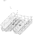
Figure 2 - is the perspective view of the rack. -
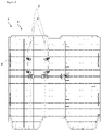
Figure 3 - is the top view of the rack when the additional wire mechanism is in the closed position. -
Figure 4 - is the schematic view of the rack when the additional wire mechanism is in the open position. -
Figure 5 - is the schematic view of the connection member and the additional wire mechanism. - The elements illustrated in the figures are numbered as follows:
- 1. Dishwasher
- 2. Body
- 3. Washing tub
- 4. Rack
- 5. Spraying member
- 6. Holding wire
- 7. Additional wire
- 8. Additional wire mechanism
- 9. Connection member
- 10. Horizontal wire
- 11. Vertical wire
- 12. Hole
- 13. First opening
- 14. Second opening
- 15. First channel
- 16. Second channel
- 17. Locking member
- 18. Protrusion
- a. Open position
- K- Closed position
- The dishwasher (1) comprises a body (2); a washing tub (3) which is arranged in the body (2) and wherein the washing process is realized; at least one rack (4) which is disposed in the washing tub (3) and whereon the dishes to be washed are placed; at least one spraying member (5) which enables the water to be sprayed onto the rack (4) and the kitchen items to be cleaned; and a plurality of holding wires (6) which are disposed on the rack (4), which enables the vertical placement of kitchen items thereon and which are positioned vertically with respect to the base of the rack (4). The kitchen items are placed onto the rack (4) to be washed. The water is delivered onto the rack (4) by means of the spraying member (5) such that the kitchen items are cleaned. The kitchen items are placed onto the holding wires (6) on the rack (4) in a certain order. The arrangement of the kitchen items on the rack significantly affects the washing and drying performance.
- The dishwasher (1) of the present invention comprises an additional wire (7) which is attached onto the holding wire (6), and an additional wire mechanism (8) having an open position (A) which, after the additional wire (7) is placed between the holding wires (6), enables the distance therebetween to be reduced and thus more kitchen items to be placed, and a closed position (K) wherein the additional wire (7) is parallel to the holding wire (6) and thus the holding wire (6) and the additional wire (7) are aligned without changing the space between the holding wires (6). When the additional wire mechanism (8) shifts to the open position (A), the additional wires (7) move to a position between the holding wires (6). Thus, more kitchen items can be placed. When the additional wire mechanism (8) shifts to the closed position (K), the additional wires (7) rest parallel to the holding wires (6) on the rack (4). Thus, the additional wires (7) do not occupy unnecessary space and cannot be detached from the rack (4).
- In an embodiment of the present invention, the dishwasher 1) comprises an additional wire mechanism (8) having a connection member (9) which is disposed between the additional wire (7) and the holding wire (6). By means of the connection member (9) attached between the additional wire (7) and the holding wire (6), the additional wire mechanism (8) is enabled to shift between the open position (A) and the closed position (K).
- In an embodiment of the present invention, the dishwasher (1) comprises the additional wire mechanism (8) comprising the additional wire (7) having a horizontal wire (10) and a plurality of vertical wires (11) extending vertically on the horizontal wire (10). The vertical wires (11) on the additional wire (7) are fixed on the horizontal wire (10). After passing over the horizontal wire (10), the vertical wires (11) continue extend towards the base of the rack (4). Thus, the rigidity of the additional wire (7) on the rack (4) is increased.
- In an embodiment of the present invention, the dishwasher (1) comprises the connection member (9) having a hole (12) which enables the same to be attached to the holding wire (6) and to rotatably move on the holding wire (6), and a first opening (13) and a second opening (14) which are disposed at the same plane as the vertical wire (11). By means of the hole (12), the connection member (9) is rotatably attached onto the holding wire (6). The vertical wires (11) pass through the first opening (13) and the second opening (14). The first opening (13) and the second opening (14) are placed parallel to each other in the same vertical axis. When the additional wire mechanism (8) is in the open position (A), the horizontal wire (10) is located between the first opening (13) and the second opening (14). Thus, the additional wire (7) is prevented from tipping over.
- In an embodiment of the present invention, the dishwasher (1) comprises the connection member (9) having a first channel (15) which is arranged between the first opening (13) and the second opening (14) and which receives the horizontal wire (10) when the additional wire mechanism (8) is in the open position (A), and a second channel (16) which is arranged on the edge of the first opening (13) and the second opening (14) and which receives the horizontal wire (10) when the additional wire mechanism (8) is in the closed position (K). When the additional wire mechanism (8) is in the open position (A), the horizontal wire (10) is placed in the first channel (15). The first channel (15) is arranged between the first opening (13) and the second opening (14). When the additional wire mechanism (8) is in the closed position (A), the horizontal wire (10) is placed in the second channel (16). The second channel (16) is arranged on the other end of the connection member (9) opposite to the hole (12).
- In an embodiment of the present invention, the dishwasher (1) comprises the connection member (9) having the first channel (15) and the second channel (16) which are almost perpendicular to each other in the same plane. While shifting between the first position and the second position, the additional wire mechanism (8) rotates almost 90°. Thus, the horizontal wire (10) moves between the first channel (15) and the second channel (16).
- In an embodiment of the present invention, the dishwasher (1) comprises a locking member (17) which is disposed on the first opening (13) and the second opening (14), which, as the vertical wire (11) enters the openings (13, 14), stretches and enables the vertical wire (11) to enter the openings (13, 14), and which, when the vertical wire (11) enters the openings (13, 14), moves into the openings (13, 14) so as to prevent the vertical wire (11) from dislodging from the openings (13, 14). By means of the locking member (17) disposed on the first opening (13) and the second opening (14), the vertical wire (11) is prevented from dislodging from the connection member (9). The locking member (17) stretches outwards as the vertical wire (11) enters the openings (13, 14), and returns to the initial state after the vertical wire (11) enters the openings (13, 14).
- In an embodiment of the present invention, the dishwasher (1) comprises the connection member (9) having at least one protrusion (18) which is disposed on the edges of the first channel (15) and the second channel (16) and which, when the horizontal wire (10) is placed into the channel (15 or 16), prevents the horizontal wire (10) from dislodging from the channel (15 or 16). By means of the protrusion (18) disposed on the edges of the first channel (15) and the second channel (16), the horizontal wire (10) is prevented from dislodging from the channel (15 or 16).
- In an embodiment of the present invention, the dishwasher (1) comprises the connection member (9) one end of which rotates around the holding wire (6) by means of the hole (12) while the additional wire mechanism (8) shifts between the open position (A) and the closed position (K), and at the other end of which the horizontal wire (10) moves between the first channel (15) and the second channel (16). The connection member (9) has the hole (12) at one end, and the second channel (16) at the other end. As the additional wire mechanism (8) shifts between the open position (A) the closed position (K), the connection member (9) rotates on the hole (12) and enables the horizontal wire (10) to move between the first channel (15) and the second channel (16).
- By means of the present invention, a dishwasher (1) is realized, comprising an additional wire mechanism (8) having an additional wire (7) which enables more items to be placed onto the rack (4). The additional wire mechanism (8) can easily shift between the open position (A) and the closed position (K). When in the closed position (K), the additional wire mechanism (8) does not occupy unnecessary space on the rack (4) and cannot be dislodged from the rack (4). Thus, ease of use is provided.
Claims (9)
- A dishwasher (1) comprising a body (2); a washing tub (3) which is arranged in the body (2) and wherein the washing process is realized; at least one rack (4) which is disposed in the washing tub (3) and whereon the dishes to be washed are placed; at least one spraying member (5) which enables the water to be sprayed onto the rack (4) and the kitchen items to be cleaned; and a plurality of holding wires (6) which are disposed on the rack (4), which enables the vertical placement of kitchen items thereon and which are positioned vertically with respect to the base of the rack (4), characterized by an additional wire (7) which is attached onto the holding wire (6), and an additional wire mechanism (8) having an open position (A) which enables the additional wire (7) to be placed between the holding wires (6) and thus more kitchen items to be placed, and a closed position (K) wherein the additional wire (7) is aligned as parallel to the holding wire (6)..
- A dishwasher (1) as in Claim 1, characterized by an additional wire mechanism (8) having a connection member (9) which is disposed between the additional wire (7) and the holding wire (6).
- A dishwasher (1) as in Claim 1 or 2, characterized by the additional wire mechanism (8) comprising the additional wire (7) having a horizontal wire (10) and a plurality of vertical wires (11) extending vertically on the horizontal wire (10).
- A dishwasher (1) as in Claim 2 or 3, characterized by the connection member (9) having a hole (12) which enables the same to be attached to the holding wire (6) and to rotatably move on the holding wire (6), and a first opening (13) and a second opening (14) which are disposed at the same plane as the vertical wire (11).
- A dishwasher (1) as in Claim 4, characterized by the connection member (9) having a first channel (15) which is arranged between the first opening (13) and the second opening (14) and which receives the horizontal wire (10) when the additional wire mechanism (8) is in the open position (A), and a second channel (16) which is arranged on the edge of the first opening (13) and the second opening (14) and which receives the horizontal wire (10) when the additional wire mechanism (8) is in the closed position (K).
- A dishwasher (1) as in Claim 5, characterized by the connection member (9) having the first channel (15) and the second channel (16) which are almost perpendicular to each other in the same plane.
- A dishwasher (1) as in any one of the Claims 4 to 6, characterized by a locking member (17) which is disposed on the first opening (13) and the second opening (14), which, as the vertical wire (11) enters the openings (13, 14), stretches and enables the vertical wire (11) to enter the openings (13, 14), and which, when the vertical wire (11) enters the openings (13, 14), moves into the openings (13, 14) so as to prevent the vertical wire (11) from dislodging from the openings (13, 14).
- A dishwasher as in any one of the Claims 5 to 7, characterized by the connection member (9) having at least one protrusion (18) which is disposed on the edges of the first channel (15) and the second channel (16) and which, when the horizontal wire (10) is placed into the channel (15 or 16), prevents the horizontal wire (10) from dislodging from the channel (15 or 16).
- A dishwasher (1) as any one of the Claims 5 to 8, characterized by the connection member (9) one end of which rotates around the holding wire (6) by means of the hole (12) while the additional wire mechanism (8) shifts between the open position (A) and the closed position (K), and at the other end of which the horizontal wire (10) moves between the first channel (15) and the second channel (16).
Applications Claiming Priority (1)
| Application Number | Priority Date | Filing Date | Title |
|---|---|---|---|
| TR202110156 | 2021-06-22 |
Publications (2)
| Publication Number | Publication Date |
|---|---|
| EP4108152A1 true EP4108152A1 (en) | 2022-12-28 |
| EP4108152B1 EP4108152B1 (en) | 2024-02-07 |
Family
ID=84179638
Family Applications (1)
| Application Number | Title | Priority Date | Filing Date |
|---|---|---|---|
| EP22165728.1A Active EP4108152B1 (en) | 2021-06-22 | 2022-03-31 | A dishwasher comprising an additional wire mechanism |
Country Status (2)
| Country | Link |
|---|---|
| EP (1) | EP4108152B1 (en) |
| PL (1) | PL4108152T3 (en) |
Citations (6)
| Publication number | Priority date | Publication date | Assignee | Title |
|---|---|---|---|---|
| JPH04314415A (en) * | 1991-04-12 | 1992-11-05 | Mitsubishi Electric Corp | Dish cage for dish cleaner |
| EP0729725A1 (en) * | 1995-03-01 | 1996-09-04 | White Consolidated Industries, Inc. | Multi-functional dish holder |
| KR20070062653A (en) * | 2005-12-13 | 2007-06-18 | 엘지전자 주식회사 | Rack of dishwashers |
| WO2011026820A1 (en) * | 2009-09-01 | 2011-03-10 | Arcelik Anonim Sirketi | A dishwasher rack |
| WO2016034215A1 (en) * | 2014-09-03 | 2016-03-10 | Arcelik Anonim Sirketi | A dishwasher wire rack having an improved carrier adaptor tine assembly structure |
| US10722101B2 (en) | 2011-05-25 | 2020-07-28 | Whirlpool Corporation | Dishwasher with slidable tine assembly |
-
2022
- 2022-03-31 PL PL22165728.1T patent/PL4108152T3/en unknown
- 2022-03-31 EP EP22165728.1A patent/EP4108152B1/en active Active
Patent Citations (6)
| Publication number | Priority date | Publication date | Assignee | Title |
|---|---|---|---|---|
| JPH04314415A (en) * | 1991-04-12 | 1992-11-05 | Mitsubishi Electric Corp | Dish cage for dish cleaner |
| EP0729725A1 (en) * | 1995-03-01 | 1996-09-04 | White Consolidated Industries, Inc. | Multi-functional dish holder |
| KR20070062653A (en) * | 2005-12-13 | 2007-06-18 | 엘지전자 주식회사 | Rack of dishwashers |
| WO2011026820A1 (en) * | 2009-09-01 | 2011-03-10 | Arcelik Anonim Sirketi | A dishwasher rack |
| US10722101B2 (en) | 2011-05-25 | 2020-07-28 | Whirlpool Corporation | Dishwasher with slidable tine assembly |
| WO2016034215A1 (en) * | 2014-09-03 | 2016-03-10 | Arcelik Anonim Sirketi | A dishwasher wire rack having an improved carrier adaptor tine assembly structure |
Also Published As
| Publication number | Publication date |
|---|---|
| PL4108152T3 (en) | 2024-06-03 |
| EP4108152B1 (en) | 2024-02-07 |
Similar Documents
| Publication | Publication Date | Title |
|---|---|---|
| CN101573066B (en) | Dishwasher and rack assembly therefor | |
| US8714371B2 (en) | Dishwasher basket with a cup support | |
| US20120056519A1 (en) | Dishwasher | |
| US9861260B2 (en) | Dishwasher appliance and a tine assembly for a dishwasher appliance | |
| EP1686883A1 (en) | A basket for dishwashers | |
| KR20100037460A (en) | Rack assembly of washing machine | |
| US20130299438A1 (en) | Removable tine block assembly for a dishwashing appliance | |
| WO2013053720A1 (en) | A rack suitable for usage in a dishwasher and the dishwasher wherein the rack is used | |
| KR102864929B1 (en) | Dish Washer | |
| EP4108152B1 (en) | A dishwasher comprising an additional wire mechanism | |
| EP1286616B1 (en) | Dishwasher basket with foldable crockery holder racks | |
| EP3791770B1 (en) | A dishwasher comprising a bottle holder | |
| US11330961B1 (en) | Dishwasher appliance with stemware holder assembly | |
| US5330102A (en) | Spray arm inlet for dishwasher | |
| WO2022121794A1 (en) | Article holder assembly for use in dishwasher device | |
| KR102859666B1 (en) | Dish Washer | |
| KR101330839B1 (en) | Rack of dish washer | |
| EP2473087B1 (en) | A dishwasher rack | |
| US12383114B2 (en) | Dish washer | |
| KR20140033693A (en) | Dish washer and basket thereof | |
| EP4578370A1 (en) | A dishwasher comprising movable wires | |
| CN222853818U (en) | Dishwasher support and dishwasher | |
| CN220024991U (en) | Shelf assembly for dish washing machine and dish washing machine | |
| EP4566508A1 (en) | A dishwasher comprising a fixing member | |
| EP4238473B1 (en) | A dishwasher comprising movable plate wires |
Legal Events
| Date | Code | Title | Description |
|---|---|---|---|
| PUAI | Public reference made under article 153(3) epc to a published international application that has entered the european phase |
Free format text: ORIGINAL CODE: 0009012 |
|
| STAA | Information on the status of an ep patent application or granted ep patent |
Free format text: STATUS: REQUEST FOR EXAMINATION WAS MADE |
|
| 17P | Request for examination filed |
Effective date: 20220331 |
|
| AK | Designated contracting states |
Kind code of ref document: A1 Designated state(s): AL AT BE BG CH CY CZ DE DK EE ES FI FR GB GR HR HU IE IS IT LI LT LU LV MC MK MT NL NO PL PT RO RS SE SI SK SM TR |
|
| GRAP | Despatch of communication of intention to grant a patent |
Free format text: ORIGINAL CODE: EPIDOSNIGR1 |
|
| STAA | Information on the status of an ep patent application or granted ep patent |
Free format text: STATUS: GRANT OF PATENT IS INTENDED |
|
| INTG | Intention to grant announced |
Effective date: 20231011 |
|
| GRAS | Grant fee paid |
Free format text: ORIGINAL CODE: EPIDOSNIGR3 |
|
| GRAA | (expected) grant |
Free format text: ORIGINAL CODE: 0009210 |
|
| STAA | Information on the status of an ep patent application or granted ep patent |
Free format text: STATUS: THE PATENT HAS BEEN GRANTED |
|
| AK | Designated contracting states |
Kind code of ref document: B1 Designated state(s): AL AT BE BG CH CY CZ DE DK EE ES FI FR GB GR HR HU IE IS IT LI LT LU LV MC MK MT NL NO PL PT RO RS SE SI SK SM TR |
|
| REG | Reference to a national code |
Ref country code: GB Ref legal event code: FG4D |
|
| REG | Reference to a national code |
Ref country code: CH Ref legal event code: EP |
|
| REG | Reference to a national code |
Ref country code: IE Ref legal event code: FG4D |
|
| REG | Reference to a national code |
Ref country code: DE Ref legal event code: R096 Ref document number: 602022001835 Country of ref document: DE |
|
| REG | Reference to a national code |
Ref country code: LT Ref legal event code: MG9D |
|
| REG | Reference to a national code |
Ref country code: NL Ref legal event code: MP Effective date: 20240207 |
|
| PG25 | Lapsed in a contracting state [announced via postgrant information from national office to epo] |
Ref country code: IS Free format text: LAPSE BECAUSE OF FAILURE TO SUBMIT A TRANSLATION OF THE DESCRIPTION OR TO PAY THE FEE WITHIN THE PRESCRIBED TIME-LIMIT Effective date: 20240607 |
|
| PG25 | Lapsed in a contracting state [announced via postgrant information from national office to epo] |
Ref country code: LT Free format text: LAPSE BECAUSE OF FAILURE TO SUBMIT A TRANSLATION OF THE DESCRIPTION OR TO PAY THE FEE WITHIN THE PRESCRIBED TIME-LIMIT Effective date: 20240207 |
|
| PG25 | Lapsed in a contracting state [announced via postgrant information from national office to epo] |
Ref country code: GR Free format text: LAPSE BECAUSE OF FAILURE TO SUBMIT A TRANSLATION OF THE DESCRIPTION OR TO PAY THE FEE WITHIN THE PRESCRIBED TIME-LIMIT Effective date: 20240508 |
|
| REG | Reference to a national code |
Ref country code: AT Ref legal event code: MK05 Ref document number: 1654813 Country of ref document: AT Kind code of ref document: T Effective date: 20240207 |
|
| PG25 | Lapsed in a contracting state [announced via postgrant information from national office to epo] |
Ref country code: RS Free format text: LAPSE BECAUSE OF FAILURE TO SUBMIT A TRANSLATION OF THE DESCRIPTION OR TO PAY THE FEE WITHIN THE PRESCRIBED TIME-LIMIT Effective date: 20240507 Ref country code: NL Free format text: LAPSE BECAUSE OF FAILURE TO SUBMIT A TRANSLATION OF THE DESCRIPTION OR TO PAY THE FEE WITHIN THE PRESCRIBED TIME-LIMIT Effective date: 20240207 Ref country code: HR Free format text: LAPSE BECAUSE OF FAILURE TO SUBMIT A TRANSLATION OF THE DESCRIPTION OR TO PAY THE FEE WITHIN THE PRESCRIBED TIME-LIMIT Effective date: 20240207 |
|
| PG25 | Lapsed in a contracting state [announced via postgrant information from national office to epo] |
Ref country code: ES Free format text: LAPSE BECAUSE OF FAILURE TO SUBMIT A TRANSLATION OF THE DESCRIPTION OR TO PAY THE FEE WITHIN THE PRESCRIBED TIME-LIMIT Effective date: 20240207 |
|
| PG25 | Lapsed in a contracting state [announced via postgrant information from national office to epo] |
Ref country code: AT Free format text: LAPSE BECAUSE OF FAILURE TO SUBMIT A TRANSLATION OF THE DESCRIPTION OR TO PAY THE FEE WITHIN THE PRESCRIBED TIME-LIMIT Effective date: 20240207 |
|
| PG25 | Lapsed in a contracting state [announced via postgrant information from national office to epo] |
Ref country code: RS Free format text: LAPSE BECAUSE OF FAILURE TO SUBMIT A TRANSLATION OF THE DESCRIPTION OR TO PAY THE FEE WITHIN THE PRESCRIBED TIME-LIMIT Effective date: 20240507 Ref country code: NO Free format text: LAPSE BECAUSE OF FAILURE TO SUBMIT A TRANSLATION OF THE DESCRIPTION OR TO PAY THE FEE WITHIN THE PRESCRIBED TIME-LIMIT Effective date: 20240507 Ref country code: NL Free format text: LAPSE BECAUSE OF FAILURE TO SUBMIT A TRANSLATION OF THE DESCRIPTION OR TO PAY THE FEE WITHIN THE PRESCRIBED TIME-LIMIT Effective date: 20240207 Ref country code: LT Free format text: LAPSE BECAUSE OF FAILURE TO SUBMIT A TRANSLATION OF THE DESCRIPTION OR TO PAY THE FEE WITHIN THE PRESCRIBED TIME-LIMIT Effective date: 20240207 Ref country code: IS Free format text: LAPSE BECAUSE OF FAILURE TO SUBMIT A TRANSLATION OF THE DESCRIPTION OR TO PAY THE FEE WITHIN THE PRESCRIBED TIME-LIMIT Effective date: 20240607 Ref country code: HR Free format text: LAPSE BECAUSE OF FAILURE TO SUBMIT A TRANSLATION OF THE DESCRIPTION OR TO PAY THE FEE WITHIN THE PRESCRIBED TIME-LIMIT Effective date: 20240207 Ref country code: GR Free format text: LAPSE BECAUSE OF FAILURE TO SUBMIT A TRANSLATION OF THE DESCRIPTION OR TO PAY THE FEE WITHIN THE PRESCRIBED TIME-LIMIT Effective date: 20240508 Ref country code: FI Free format text: LAPSE BECAUSE OF FAILURE TO SUBMIT A TRANSLATION OF THE DESCRIPTION OR TO PAY THE FEE WITHIN THE PRESCRIBED TIME-LIMIT Effective date: 20240207 Ref country code: ES Free format text: LAPSE BECAUSE OF FAILURE TO SUBMIT A TRANSLATION OF THE DESCRIPTION OR TO PAY THE FEE WITHIN THE PRESCRIBED TIME-LIMIT Effective date: 20240207 Ref country code: BG Free format text: LAPSE BECAUSE OF FAILURE TO SUBMIT A TRANSLATION OF THE DESCRIPTION OR TO PAY THE FEE WITHIN THE PRESCRIBED TIME-LIMIT Effective date: 20240207 Ref country code: AT Free format text: LAPSE BECAUSE OF FAILURE TO SUBMIT A TRANSLATION OF THE DESCRIPTION OR TO PAY THE FEE WITHIN THE PRESCRIBED TIME-LIMIT Effective date: 20240207 |
|
| PG25 | Lapsed in a contracting state [announced via postgrant information from national office to epo] |
Ref country code: PT Free format text: LAPSE BECAUSE OF FAILURE TO SUBMIT A TRANSLATION OF THE DESCRIPTION OR TO PAY THE FEE WITHIN THE PRESCRIBED TIME-LIMIT Effective date: 20240607 |
|
| PG25 | Lapsed in a contracting state [announced via postgrant information from national office to epo] |
Ref country code: SE Free format text: LAPSE BECAUSE OF FAILURE TO SUBMIT A TRANSLATION OF THE DESCRIPTION OR TO PAY THE FEE WITHIN THE PRESCRIBED TIME-LIMIT Effective date: 20240207 Ref country code: PT Free format text: LAPSE BECAUSE OF FAILURE TO SUBMIT A TRANSLATION OF THE DESCRIPTION OR TO PAY THE FEE WITHIN THE PRESCRIBED TIME-LIMIT Effective date: 20240607 Ref country code: LV Free format text: LAPSE BECAUSE OF FAILURE TO SUBMIT A TRANSLATION OF THE DESCRIPTION OR TO PAY THE FEE WITHIN THE PRESCRIBED TIME-LIMIT Effective date: 20240207 |
|
| PG25 | Lapsed in a contracting state [announced via postgrant information from national office to epo] |
Ref country code: DK Free format text: LAPSE BECAUSE OF FAILURE TO SUBMIT A TRANSLATION OF THE DESCRIPTION OR TO PAY THE FEE WITHIN THE PRESCRIBED TIME-LIMIT Effective date: 20240207 |
|
| PG25 | Lapsed in a contracting state [announced via postgrant information from national office to epo] |
Ref country code: SM Free format text: LAPSE BECAUSE OF FAILURE TO SUBMIT A TRANSLATION OF THE DESCRIPTION OR TO PAY THE FEE WITHIN THE PRESCRIBED TIME-LIMIT Effective date: 20240207 |
|
| PG25 | Lapsed in a contracting state [announced via postgrant information from national office to epo] |
Ref country code: CZ Free format text: LAPSE BECAUSE OF FAILURE TO SUBMIT A TRANSLATION OF THE DESCRIPTION OR TO PAY THE FEE WITHIN THE PRESCRIBED TIME-LIMIT Effective date: 20240207 Ref country code: EE Free format text: LAPSE BECAUSE OF FAILURE TO SUBMIT A TRANSLATION OF THE DESCRIPTION OR TO PAY THE FEE WITHIN THE PRESCRIBED TIME-LIMIT Effective date: 20240207 |
|
| PG25 | Lapsed in a contracting state [announced via postgrant information from national office to epo] |
Ref country code: SK Free format text: LAPSE BECAUSE OF FAILURE TO SUBMIT A TRANSLATION OF THE DESCRIPTION OR TO PAY THE FEE WITHIN THE PRESCRIBED TIME-LIMIT Effective date: 20240207 |
|
| PG25 | Lapsed in a contracting state [announced via postgrant information from national office to epo] |
Ref country code: SM Free format text: LAPSE BECAUSE OF FAILURE TO SUBMIT A TRANSLATION OF THE DESCRIPTION OR TO PAY THE FEE WITHIN THE PRESCRIBED TIME-LIMIT Effective date: 20240207 Ref country code: SK Free format text: LAPSE BECAUSE OF FAILURE TO SUBMIT A TRANSLATION OF THE DESCRIPTION OR TO PAY THE FEE WITHIN THE PRESCRIBED TIME-LIMIT Effective date: 20240207 Ref country code: RO Free format text: LAPSE BECAUSE OF FAILURE TO SUBMIT A TRANSLATION OF THE DESCRIPTION OR TO PAY THE FEE WITHIN THE PRESCRIBED TIME-LIMIT Effective date: 20240207 Ref country code: EE Free format text: LAPSE BECAUSE OF FAILURE TO SUBMIT A TRANSLATION OF THE DESCRIPTION OR TO PAY THE FEE WITHIN THE PRESCRIBED TIME-LIMIT Effective date: 20240207 Ref country code: DK Free format text: LAPSE BECAUSE OF FAILURE TO SUBMIT A TRANSLATION OF THE DESCRIPTION OR TO PAY THE FEE WITHIN THE PRESCRIBED TIME-LIMIT Effective date: 20240207 Ref country code: CZ Free format text: LAPSE BECAUSE OF FAILURE TO SUBMIT A TRANSLATION OF THE DESCRIPTION OR TO PAY THE FEE WITHIN THE PRESCRIBED TIME-LIMIT Effective date: 20240207 |
|
| REG | Reference to a national code |
Ref country code: DE Ref legal event code: R097 Ref document number: 602022001835 Country of ref document: DE |
|
| PG25 | Lapsed in a contracting state [announced via postgrant information from national office to epo] |
Ref country code: LU Free format text: LAPSE BECAUSE OF NON-PAYMENT OF DUE FEES Effective date: 20240331 |
|
| PG25 | Lapsed in a contracting state [announced via postgrant information from national office to epo] |
Ref country code: MC Free format text: LAPSE BECAUSE OF FAILURE TO SUBMIT A TRANSLATION OF THE DESCRIPTION OR TO PAY THE FEE WITHIN THE PRESCRIBED TIME-LIMIT Effective date: 20240207 |
|
| PG25 | Lapsed in a contracting state [announced via postgrant information from national office to epo] |
Ref country code: MC Free format text: LAPSE BECAUSE OF FAILURE TO SUBMIT A TRANSLATION OF THE DESCRIPTION OR TO PAY THE FEE WITHIN THE PRESCRIBED TIME-LIMIT Effective date: 20240207 Ref country code: LU Free format text: LAPSE BECAUSE OF NON-PAYMENT OF DUE FEES Effective date: 20240331 |
|
| PLBE | No opposition filed within time limit |
Free format text: ORIGINAL CODE: 0009261 |
|
| STAA | Information on the status of an ep patent application or granted ep patent |
Free format text: STATUS: NO OPPOSITION FILED WITHIN TIME LIMIT |
|
| REG | Reference to a national code |
Ref country code: BE Ref legal event code: MM Effective date: 20240331 |
|
| 26N | No opposition filed |
Effective date: 20241108 |
|
| PG25 | Lapsed in a contracting state [announced via postgrant information from national office to epo] |
Ref country code: BE Free format text: LAPSE BECAUSE OF NON-PAYMENT OF DUE FEES Effective date: 20240331 |
|
| PG25 | Lapsed in a contracting state [announced via postgrant information from national office to epo] |
Ref country code: IE Free format text: LAPSE BECAUSE OF NON-PAYMENT OF DUE FEES Effective date: 20240331 |
|
| PG25 | Lapsed in a contracting state [announced via postgrant information from national office to epo] |
Ref country code: IE Free format text: LAPSE BECAUSE OF NON-PAYMENT OF DUE FEES Effective date: 20240331 Ref country code: BE Free format text: LAPSE BECAUSE OF NON-PAYMENT OF DUE FEES Effective date: 20240331 |
|
| PG25 | Lapsed in a contracting state [announced via postgrant information from national office to epo] |
Ref country code: SI Free format text: LAPSE BECAUSE OF FAILURE TO SUBMIT A TRANSLATION OF THE DESCRIPTION OR TO PAY THE FEE WITHIN THE PRESCRIBED TIME-LIMIT Effective date: 20240207 |
|
| PG25 | Lapsed in a contracting state [announced via postgrant information from national office to epo] |
Ref country code: CY Free format text: LAPSE BECAUSE OF FAILURE TO SUBMIT A TRANSLATION OF THE DESCRIPTION OR TO PAY THE FEE WITHIN THE PRESCRIBED TIME-LIMIT; INVALID AB INITIO Effective date: 20220331 |
|
| REG | Reference to a national code |
Ref country code: CH Ref legal event code: H13 Free format text: ST27 STATUS EVENT CODE: U-0-0-H10-H13 (AS PROVIDED BY THE NATIONAL OFFICE) Effective date: 20251023 |
|
| PG25 | Lapsed in a contracting state [announced via postgrant information from national office to epo] |
Ref country code: CH Free format text: LAPSE BECAUSE OF NON-PAYMENT OF DUE FEES Effective date: 20250331 |
|
| PGFP | Annual fee paid to national office [announced via postgrant information from national office to epo] |
Ref country code: GB Payment date: 20260324 Year of fee payment: 5 |
|
| PGFP | Annual fee paid to national office [announced via postgrant information from national office to epo] |
Ref country code: DE Payment date: 20260319 Year of fee payment: 5 |
|
| PGFP | Annual fee paid to national office [announced via postgrant information from national office to epo] |
Ref country code: IT Payment date: 20260324 Year of fee payment: 5 |
|
| PGFP | Annual fee paid to national office [announced via postgrant information from national office to epo] |
Ref country code: FR Payment date: 20260323 Year of fee payment: 5 |
|
| PGFP | Annual fee paid to national office [announced via postgrant information from national office to epo] |
Ref country code: TR Payment date: 20260306 Year of fee payment: 5 |
|
| PGFP | Annual fee paid to national office [announced via postgrant information from national office to epo] |
Ref country code: PL Payment date: 20260319 Year of fee payment: 5 |
|
| PG25 | Lapsed in a contracting state [announced via postgrant information from national office to epo] |
Ref country code: CH Free format text: THE PATENT HAS BEEN ANNULLED BY A DECISION OF A NATIONAL AUTHORITY Effective date: 20250331 |