EP4108133A1 - Bracket system for mounting an appliance to a cabinet structure - Google Patents
Bracket system for mounting an appliance to a cabinet structure Download PDFInfo
- Publication number
- EP4108133A1 EP4108133A1 EP22171699.6A EP22171699A EP4108133A1 EP 4108133 A1 EP4108133 A1 EP 4108133A1 EP 22171699 A EP22171699 A EP 22171699A EP 4108133 A1 EP4108133 A1 EP 4108133A1
- Authority
- EP
- European Patent Office
- Prior art keywords
- apertures
- mounting
- bracket
- mounting bracket
- wall
- Prior art date
- Legal status (The legal status is an assumption and is not a legal conclusion. Google has not performed a legal analysis and makes no representation as to the accuracy of the status listed.)
- Granted
Links
Images



























Classifications
-
- F—MECHANICAL ENGINEERING; LIGHTING; HEATING; WEAPONS; BLASTING
- F25—REFRIGERATION OR COOLING; COMBINED HEATING AND REFRIGERATION SYSTEMS; HEAT PUMP SYSTEMS; MANUFACTURE OR STORAGE OF ICE; LIQUEFACTION SOLIDIFICATION OF GASES
- F25D—REFRIGERATORS; COLD ROOMS; ICE-BOXES; COOLING OR FREEZING APPARATUS NOT OTHERWISE PROVIDED FOR
- F25D11/00—Self-contained movable devices, e.g. domestic refrigerators
- F25D11/02—Self-contained movable devices, e.g. domestic refrigerators with cooling compartments at different temperatures
-
- A—HUMAN NECESSITIES
- A47—FURNITURE; DOMESTIC ARTICLES OR APPLIANCES; COFFEE MILLS; SPICE MILLS; SUCTION CLEANERS IN GENERAL
- A47B—TABLES; DESKS; OFFICE FURNITURE; CABINETS; DRAWERS; GENERAL DETAILS OF FURNITURE
- A47B77/00—Kitchen cabinets
- A47B77/04—Provision for particular uses of compartments or other parts ; Compartments moving up and down, revolving parts
- A47B77/08—Provision for particular uses of compartments or other parts ; Compartments moving up and down, revolving parts for incorporating apparatus operated by power, including water power; for incorporating apparatus for cooking, cooling, or laundry purposes
-
- F—MECHANICAL ENGINEERING; LIGHTING; HEATING; WEAPONS; BLASTING
- F25—REFRIGERATION OR COOLING; COMBINED HEATING AND REFRIGERATION SYSTEMS; HEAT PUMP SYSTEMS; MANUFACTURE OR STORAGE OF ICE; LIQUEFACTION SOLIDIFICATION OF GASES
- F25D—REFRIGERATORS; COLD ROOMS; ICE-BOXES; COOLING OR FREEZING APPARATUS NOT OTHERWISE PROVIDED FOR
- F25D23/00—General constructional features
- F25D23/06—Walls
- F25D23/062—Walls defining a cabinet
-
- F—MECHANICAL ENGINEERING; LIGHTING; HEATING; WEAPONS; BLASTING
- F25—REFRIGERATION OR COOLING; COMBINED HEATING AND REFRIGERATION SYSTEMS; HEAT PUMP SYSTEMS; MANUFACTURE OR STORAGE OF ICE; LIQUEFACTION SOLIDIFICATION OF GASES
- F25D—REFRIGERATORS; COLD ROOMS; ICE-BOXES; COOLING OR FREEZING APPARATUS NOT OTHERWISE PROVIDED FOR
- F25D23/00—General constructional features
- F25D23/06—Walls
- F25D23/065—Details
-
- F—MECHANICAL ENGINEERING; LIGHTING; HEATING; WEAPONS; BLASTING
- F25—REFRIGERATION OR COOLING; COMBINED HEATING AND REFRIGERATION SYSTEMS; HEAT PUMP SYSTEMS; MANUFACTURE OR STORAGE OF ICE; LIQUEFACTION SOLIDIFICATION OF GASES
- F25D—REFRIGERATORS; COLD ROOMS; ICE-BOXES; COOLING OR FREEZING APPARATUS NOT OTHERWISE PROVIDED FOR
- F25D23/00—General constructional features
- F25D23/06—Walls
- F25D23/065—Details
- F25D23/067—Supporting elements
-
- F—MECHANICAL ENGINEERING; LIGHTING; HEATING; WEAPONS; BLASTING
- F25—REFRIGERATION OR COOLING; COMBINED HEATING AND REFRIGERATION SYSTEMS; HEAT PUMP SYSTEMS; MANUFACTURE OR STORAGE OF ICE; LIQUEFACTION SOLIDIFICATION OF GASES
- F25D—REFRIGERATORS; COLD ROOMS; ICE-BOXES; COOLING OR FREEZING APPARATUS NOT OTHERWISE PROVIDED FOR
- F25D23/00—General constructional features
- F25D23/10—Arrangements for mounting in particular locations, e.g. for built-in type, for corner type
-
- A—HUMAN NECESSITIES
- A47—FURNITURE; DOMESTIC ARTICLES OR APPLIANCES; COFFEE MILLS; SPICE MILLS; SUCTION CLEANERS IN GENERAL
- A47B—TABLES; DESKS; OFFICE FURNITURE; CABINETS; DRAWERS; GENERAL DETAILS OF FURNITURE
- A47B96/00—Details of cabinets, racks or shelf units not covered by a single one of groups A47B43/00 - A47B95/00; General details of furniture
- A47B96/20—Furniture panels or like furniture elements
- A47B2096/208—Decorative panels for household appliances
Definitions
- the present disclosure generally relates to a bracket system for an appliance, and more specifically, to a bracket system for mounting an appliance to a cabinet structure.
- a bracket system for use between an outer surface of an appliance and an inner surface of a cabinet structure includes a mounting bracket with an inner wall spaced-apart from an outer wall with at least one sidewall that interconnects the inner wall and the outer wall.
- a channel is defined between the inner wall and the outer wall.
- a plurality of apertures is provided through the outer wall. Each aperture of the plurality of apertures opens into the channel.
- the inner wall is configured to abut the outer surface of the appliance.
- a trim member includes first and second mounting portions and an abutment portion inwardly offset from the first and second mounting portions.
- the first mounting portion includes a plurality of apertures disposed therethrough.
- One or more of the apertures of the plurality of apertures of the first mounting portion of the trim member align with one or more of the apertures of the plurality of apertures of the mounting bracket to define aligned mounting apertures therebetween.
- An inner surface of the first mounting portion abuts the outer wall of the mounting bracket and a portion of an inner surface of the abutment portion is configured to abut the outer surface of the appliance.
- the second mounting portion includes a plurality of apertures disposed therethrough. An outer surface of the second mounting portion is configured to abut the inner surface of the cabinet structure.
- a bracket system for use between an outer surface of an appliance and an inner surface of a cabinet structure includes a mounting bracket with an inner wall spaced-apart from an outer wall with an intermediate wall interconnecting the inner wall and the outer wall.
- the inner wall is configured to abut the outer surface of the appliance, and a plurality of apertures is provided through the outer wall.
- a trim member includes a front mounting portion and a rear mounting portion spaced-apart from one another along a body portion of the trim member.
- the front and rear mounting portions each include a plurality of apertures disposed therethrough.
- One or more of the apertures of the plurality of apertures of the rear mounting portion of the trim member align with one or more of the apertures of the plurality of apertures of the mounting bracket to define aligned mounting apertures therebetween.
- An inner surface of the rear mounting portion abuts the outer wall of the mounting bracket.
- An outer surface of the front mounting portion is configured to abut the inner surface of the cabinet structure.
- an appliance mounting system includes an appliance having a sidewall with an outer surface.
- a mounting bracket includes an inner wall spaced-apart from an outer wall.
- the outer wall includes a plurality of apertures provided therethrough.
- the inner wall is coupled to the outer surface of the sidewall of the appliance.
- a trim member includes first and second mounting portions.
- the first mounting portion and the second mounting portion each include a plurality of apertures disposed therethrough.
- One or more of the apertures of the plurality of apertures of the first mounting portion of the trim member align with one or more of the apertures of the plurality of apertures of the mounting bracket to define aligned mounting apertures therebetween.
- An inner surface of the first mounting portion abuts the outer wall of the mounting bracket.
- a cabinet structure includes a sidewall with an inner surface to at least partially define a cabinet enclosure. The appliance is received within the cabinet enclosure of the cabinet structure.
- An outer surface of the second mounting portion of the trim member abuts the inner surface of the sidewall of the cabinet structure.
- the present illustrated embodiments reside primarily in combinations of method steps and apparatus components related to a bracket system for mounting an appliance to a cabinet structure. Accordingly, the apparatus components and method steps have been represented, where appropriate, by conventional symbols in the drawings, showing only those specific details that are pertinent to understanding the embodiments of the present disclosure so as not to obscure the disclosure with details that will be readily apparent to those of ordinary skill in the art having the benefit of the description herein. Further, like numerals in the description and drawings represent like elements.
- the terms “upper,” “lower,” “right,” “left,” “rear,” “front,” “vertical,” “horizontal,” and derivatives thereof shall relate to the disclosure as oriented in FIG. 1 .
- the term “front” shall refer to the surface of the element closer to an intended viewer, and the term “rear” shall refer to the surface of the element further from the intended viewer.
- the disclosure may assume various alternative orientations, except where expressly specified to the contrary.
- the specific devices and processes illustrated in the attached drawings, and described in the following specification are simply exemplary embodiments of the inventive concepts defined in the appended claims. Hence, specific dimensions and other physical characteristics relating to the embodiments disclosed herein are not to be considered as limiting, unless the claims expressly state otherwise.
- substantially is intended to note that a described feature is equal or approximately equal to a value or description.
- a “substantially planar” surface is intended to denote a surface that is planar or approximately planar.
- substantially is intended to denote that two values are equal or approximately equal.
- substantially may denote values within about 10% of each other, such as within about 5% of each other, or within about 2% of each other.
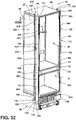
- reference numeral 10 generally designates an appliance shown in the form of a refrigerator that includes a vacuum insulated cabinet structure 12.
- the refrigerator 10 is shown without doors to reveal a refrigerator compartment 14 and a freezer compartment 16.
- the vacuum insulated cabinet structure 12 of the refrigerator 10 is contemplated to be comprised of one or more liners 18, 19 and an external wrapper 20.
- Liner 18 is contemplated to be a refrigerator liner having a top wall 22, a bottom wall 24, first and second sidewalls 26, 28, and a rear wall 30, which cooperate together to define the parameters of the refrigerator compartment 14.
- liner 19 is contemplated to be a freezer liner having a top wall 32, a bottom wall 34, first and second sidewalls 36, 38, and a rear wall 40, which cooperate together to define the parameters of the freezer compartment 16.
- the external wrapper 20 includes a top wall 42, first and second sidewalls 46, 48, and a rear wall 50, which cooperate together to define the outer parameters of the refrigerator 10.
- the external wrapper 20 and the one or more liners 18, 19 may be interconnected by a trim breaker 52 in a sealed manner to define a vacuum cavity 54 therebetween, as best shown in FIG. 7 .
- the trim breaker 52 includes a front edge 53 defining a front portion of the vacuum insulated cabinet structure 12.
- the vacuum cavity 54 defined between the external wrapper 20 and the one or more liners 18, 19 may have an air pressure level of less than about 1 atm, about 0.5 atm, about 0.4 atm, about 0.3 atm, about 0.2 atm, about 0.1 atm, about 0.01 atm, or less than about 0.001 atm.
- the vacuum cavity 54 includes a vacuum drawn thereon which provides an overall negative internal pressure within the vacuum cavity 54.
- the vacuum cavity 54 serves as an insulator to help retain the desired cold temperatures within the refrigerator compartment 14 and the freezer compartment 16.
- the external wrapper 20 and the liners 18, 19 may be comprised of a metal material suitable to retain the vacuum within the vacuum cavity 54.
- the refrigerator 10 includes a machine room cover 56 configured to house the components of a refrigeration system 58 for cooling the refrigerator compartment 14 and the freezer compartment 16.
- the machine room cover 56 may also be comprised of a metal material. It is to be understood that the features, as set forth herein, could be applied to any appliance having any general configuration, such as the rectangular configuration of the refrigerator 10 shown in FIG. 1 . As such, the refrigerator 10 may be referred to herein as an appliance that is configured for reception within a cabinet structure 60.
- the cabinet structure 60 includes a top wall 62 with an inner surface 63, a bottom wall 64 with an inner surface 65, a first sidewall 66 with an inner surface 67, a second sidewall 68 with an inner surface 69 ( FIG. 2 ), and a rear wall 70 with an inner surface 71, which all cooperate together to define a cabinet enclosure 80 in which the refrigerator 10 is configured to be received.
- the bottom wall 64 may be a support surface, such as a floor, upon which the cabinet structure 60 is abuttingly supported.
- the first sidewall 46 of the refrigerator 10 includes an outer surface 47 that is configured to align with the inner surface 67 of the first sidewall 66 of the cabinet structure 60 when the refrigerator 10 is received within the cabinet enclosure 80.
- the second sidewall 48 of the refrigerator 10 includes an outer surface 49 that is configured to align with the inner surface 69 of the second sidewall 68 of the cabinet structure 60 when the refrigerator 10 is received within the cabinet enclosure 80.
- the top wall 42 of the refrigerator 10 includes an outer surface 43 that is configured to align with the inner surface 63 of the top wall 62 of the cabinet structure 60 when the refrigerator 10 is received within the cabinet enclosure 80.
- a bracket system is provided, as further described below.
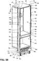
- the refrigerator 10 is shown with a side-mounting bracket system 82 shown exploded away from the outer surface 47 of the first sidewall 46 of the refrigerator 10.
- the side-mounting bracket system 82 includes a mounting bracket 90 and a trim member 92. Both the mounting bracket 90 and the trim member 92 are elongate members configured to couple to one another.
- the mounting bracket 90 is contemplated to be comprised of a metal material suitable for welding to the outer surface 47 of the first sidewall 46 of the refrigerator 10. In this way, the mounting bracket 90 can be fixedly coupled to the outer surface 47 of the first sidewall 46 of the refrigerator 10.
- the trim member 92 can then be mounted to the mounting bracket 90.
- the trim member 92 is mounted to the mounting bracket 90 using fasteners, as further described below.
- the trim member 92 is shown mounted to the first sidewall 46 of the external wrapper 20 of the refrigerator 10. Mounting of the trim member 92 to the refrigerator 10 is further described in more detail below.
- FIG. 3C the refrigerator 10 is shown received within the cabinet structure 60.
- the mounting bracket 90 is shown from a crossectional view.
- the mounting bracket 90 includes an inner wall 94 spaced-apart from an outer wall 96 with a first sidewall 98 interconnecting the inner wall 94 and the outer wall 96.
- a second sidewall 99 extends outwardly from the inner wall 94 of the mounting bracket 90 towards the outer wall 96 of the mounting bracket 90.
- a channel 100 is defined between the inner wall 94, the outer wall 96 and the first and second sidewalls 98, 99.
- the inner wall 94 and the outer wall 96 both extend in a forward direction from the first sidewall 98, in the embodiment shown in FIG. 4 .
- a plurality of apertures 102 is provided through the outer wall 96, as best shown in FIG. 3A as apertures 104, 106, 108 and 110 which are vertically spaced-apart along a length of a body portion 112 of the mounting bracket 90.
- Each aperture 104, 106, 108 and 110 of the plurality of apertures 102 opens into the channel 100.
- the mounting bracket 90 includes the body portion 112 having first and second ends 114, 116, such that the mounting bracket 90 is contemplated to be comprised of an extruded or roll-formed sheet metal material that is shaped into the inner wall 94, the outer wall 96 and the first and second sidewalls 98, 99.
- the second end 116 of the body portion 112 is disposed on the second sidewall 99, and is spaced-apart from the outer wall 96 of the mounting bracket 90 to define an opening 118 into the channel 100 of the mounting bracket 90.
- the body portion 112 of the mounting bracket 90 includes upper and lower ends 120, 122, and it is contemplated that the opening 118 of the mounting bracket 90 runs the length of the body portion 112 between the upper and lower ends 120, 122.
- the inner wall 94 and the outer wall 96 of the mounting bracket 90 are generally planar walls that run substantially parallel to one another, and include respective outer surfaces 95, 97.
- the outer surface 95 of the inner wall 94 is configured to abut the outer surface 47 of the first sidewall 46 of the refrigerator 10 in assembly, and is contemplated to be welded thereto to fixedly couple the mounting bracket 90 to the refrigerator 10.
- the trim member 92 is shown from a crossectional view.
- the trim member 92 includes an overall body portion 124 with first and second mounting portions 126, 128 and an abutment portion 130 that is inwardly offset from the first and second mounting portions 126, 128.
- the first mounting portion 126 includes a plurality of apertures 132 disposed therethrough.
- the plurality of apertures 132 is best shown in FIG. 3A as apertures 134, 136, 138 and 140 which are vertically spaced-apart along a length of the overall body portion 124 of the trim member 92.
- the apertures 134, 136, 138 and 140 of the plurality of apertures 132 of the trim member 92 are configured to align with the apertures 104, 106, 108 and 110 of the plurality of apertures 102 of the mounting bracket 90 to define aligned mounting apertures therebetween, as further described below.
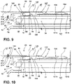
- An inner surface 127 of the first mounting portion 126 abuts the outer surface 97 of the outer wall 96 of the mounting bracket 90 in assembly, as best shown in FIGS. 7-10 .
- a portion of an inner surface 131 of the abutment portion 130 is configured to abut the outer surface 47 of the first sidewall 46 of the refrigerator 10 in assembly.
- the second mounting portion 128 includes a plurality of apertures 142 disposed therethrough as best shown in FIG.
- the second mounting portion 128 includes an outer surface 129 that extends over the first mounting portion 126, and is configured to abut the inner surface 67 of the first sidewall 66 of the cabinet enclosure 80, as best shown in FIG. 9 .
- the apertures 143, 144, 146, 148, 150, 152 and 153 of the plurality of apertures 142 of the trim member 92 are used to couple the trim member 92 to the cabinet structure 60 using fasteners, as further described below.
- the first mounting portion 126 is disposed rearward from the second mounting portion 128.
- first mounting portion 126 may be referred to herein as the rear mounting portion, while the second mounting portion 128 may be referred to herein as the front mounting portion. It is contemplated that any number of apertures can be used with the trim member 92 to mount the same to the cabinet structure 60 and the mounting bracket 90. Similarly, it is contemplated that any number of apertures can be used with the mounting bracket 90 for mounting the trim member 92 thereto.
- the trim member 92 includes the overall body portion 124 having upper and lower ends 156, 158, with the plurality of apertures 142 vertically spaced-apart along a length thereof. Apertures 143, 144, 146, 148, 150, 152 and 153 of the plurality of apertures 142 are positioned adjacent to a front edge 160 of the trim member 92.
- the upper end 156 of the trim member 92 includes an upper mounting aperture 166, and the lower end 158 of the trim member 92 includes a lower mounting aperture 168.
- the upper mounting aperture 166 is configured to couple to an upper bracket system, as further described below.
- the lower mounting aperture 168 is configured to couple to the machine room cover 56, as further described below.
- the overall body portion 124 of the trim member 92 shows the upper end 156 thereof extending above the top wall 42 of the external wrapper 20, such that the same is accessible for mounting to an upper bracket system.
- the overall body portion 124 of the trim member 92 shows the lower end 158 thereof extending below the vacuum insulated cabinet structure 12 to abut the machine room cover 56 In this way, the lower mounting aperture 168 is accessible for mounting to a mounting aperture 468 of the machine room cover 56 in assembly.
- a second trim member 92A is shown mounted to the second sidewall 48 of the external wrapper 20.
- the second trim member 92A is contemplated to be a mirror image of the first trim member 92, such that like reference numerals are provided thereon to indicate common features shared between the trim members 92, 92A.
- the front edge 160 of the second trim member 92A extends outwardly from the front edge 53 of the vacuum insulated cabinet structure 12 of the refrigerator 10. In this way, the plurality of apertures 132 of the second trim member 92A are accessible in an outboard manner relative to the front edge 53 of the vacuum insulated cabinet structure 12 of the refrigerator 10 when the refrigerator 10 is received in the cabinet enclosure 80 of the cabinet structure 60.
- the same can be securely fastened to the cabinet structure 60 using fasteners after the refrigerator 10 is positioned within the cabinet structure 60.
- the same outboard configuration is also provided for the plurality of apertures 132 of trim member 92 for coupling to the cabinet structure 60 when the refrigerator 10 is disposed within the cabinet enclosure 80 of the cabinet structure 60, as shown in FIG. 3C and further described below with reference to FIGS. 9-10 .
- the refrigerator 10 is received within the cabinet enclosure 80 of the cabinet structure 60 with the trim members 92, 92A coupled on opposite sides thereof and ready for fastening to the first and second sidewalls 66, 68 of the cabinet structure 60, respectively.
- the trim member 92 is shown with the first mounting portion 126 having a body portion 170 with a thickness 172.
- the second mounting portion 128 is shown having a body portion 174 with a thickness 176.
- the abutment portion 130 is shown having a body portion 178 with a thickness 180. Together, the collective body portions 170, 174, 178 make up the overall body portion 124 of the trim member 92.
- the thickness 172 of the body portion 170 of the first mounting portion 126 is less than the thickness 176 of the body portion 174 of the second mounting portion 128, and is less than the thickness 180 of the body portion 178 of the abutment portion 130. As shown in FIG.
- the second mounting portion 128 includes a tab 182 inwardly extending from an inner surface 133 of the second mounting portion 128.
- the tab 182 includes a distal end 184 which may abut an outer portion of the external wrapper 20 of the refrigerator 10 in assembly.
- the trim member 92 further includes an inwardly angled transverse portion 185 disposed between the first mounting portion 126 and the abutment portion 130 which inwardly offsets the abutment portion 130 relative to the first and second mounting portions 126, 128.
- the inner surface 131 of the abutment portion 130 of the trim member 92 includes first and second abutment locations 131A, 131B that are configured to abut the outer surface 47 of the first sidewall 46 of the refrigerator 10 in assembly, as best shown in FIGS. 7-10 .
- An outwardly extending interconnecting web 186 is disposed between and interconnects the first and second abutment locations 131A, 131B of the abutment portion 130 of the trim member 92.
- the mounting bracket 90 is shown coupled to the outer surface 47 of the first sidewall 46 of the external wrapper 20 of the refrigerator 10.
- the mounting bracket 90 is a metal bracket configured for welding to the first sidewall 46 of the external wrapper 20, which is also contemplated to be comprised of a metal material.
- the mounting bracket 90 is fixedly coupled to the first sidewall 46 of the external wrapper 20.
- the mounting bracket 90 does not extend above or below the first sidewall 46 of the external wrapper 20, as mounted thereto.
- the apertures 104, 106, 108 and 110 of the plurality of apertures 102 disposed on the outer wall 96 of the mounting bracket 90 are exposed and ready for alignment with the apertures 134, 136, 138 and 140 of the trim member 92.
- apertures 134, 136, 138 and 140 of the trim member 92 are configured to align with the apertures 104, 106, 108 and 110 of the mounting bracket 90 to define aligned mounting apertures therebetween.
- the apertures 104, 106, 108 and 110 of the plurality of apertures 102 disposed on the outer wall 96 of the mounting bracket 90 are configured to receive a threaded insert 200, as shown in the zoomed in portion of FIG. 6 .
- the threaded insert 200 may be welded into place, or could also be a friction fit or self-cinching member, such as a swage nut.
- the threaded insert 200 includes a threaded inner cavity 202 that is configured to threadingly engage a threaded fastener.
- the first sidewall 46 of the cabinet structure 60 is shown exploded away from the trim member 92.
- the apertures 143, 144, 146, 148, 150, 152 and 153 of the plurality of apertures 142 of the trim member 92 are used to couple the trim member 92 to the first sidewall 46 cabinet structure 60 using fasteners, as best shown in FIGS. 9-10 .
- the front edge 160 of the trim member 92 is outwardly positioned relative to the front edge 53 of the vacuum insulated cabinet structure 12 of the refrigerator 10, as shown in FIGS. 7-10 .
- apertures 143, 144, 146, 148, 150, 152 and 153 of the plurality of apertures 142 of the trim member 92 are positioned adjacent to the front edge 160 of the trim member 92. In this way, the apertures 143, 144, 146, 148, 150, 152 and 153 of the plurality of apertures 142 of the trim member 92 are accessible when the refrigerator 10 is positioned within the cabinet enclosure 80 for fastening the trim member 92 to the cabinet structure 60, as shown in FIG. 3C .
- FIG. 7 a cross-sectional view of the refrigerator 10 of FIG. 6 is shown with the trim member 92 positioned in an abutting position relative to the mounting bracket 90 for mounting the trim member 92 on the mounting bracket 90.
- the outer wall 96 of the mounting bracket 90 abuts the inner surface 127 of the first mounting portion 126 of the trim member 92.
- the inner wall 94 of the mounting bracket 90 abuts the outer surface 47 of the first sidewall 46 of the external wrapper 20, as welded thereto.
- the mounting bracket 90 By welding the mounting bracket 90 to the outer surface 47 of the first sidewall 46 of the external wrapper 20, the mounting bracket 90 is securely mounted thereto without using fasteners which may pierce the external wrapper 20 and thereby cause the vacuum cavity 54 to lose its negative pressure, and its enhanced insulating properties as well.
- the abutment portion 130 of the trim member 92 includes the first and second abutment locations 131A, 131B which are shown abutting the outer surface 47 of the first sidewall 46 of the external wrapper 20.
- the external wrapper 20 and the liner 18 are interconnected by the trim breaker 52 in a sealed manner to define the vacuum cavity 54 of the vacuum insulated cabinet structure 12 therebetween.
- a fastener 204 includes a head portion 206 and a threaded shaft portion 208.
- the threaded shaft portion 208 is contemplated to have a complimentary thread pattern relative to the threaded inner cavity 202 of the threaded insert 200 to threadingly engage the same, as shown in FIG. 8 .
- the fastener 204 may be a machine screw, or other like fastener.
- the head portion 206 of the fastener 204 abuts the outer surface 129 of the first mounting portion 126 of the trim member 92 to secure the trim member 92 to the mounting bracket 90.
- Aperture 104 of the mounting bracket 90 is shown aligned with aperture 134 of the trim member 92 in FIGS. 7 and 8 , however, it is contemplated that apertures 106, 108 and 110 (which are spaced-apart along a length of the mounting bracket 90) are also aligned with respective apertures 136, 138 and 140 (which are spaced-apart along a length of the trim member 92) to securely mount the trim member 92 to the mounting bracket 90 using fasteners, like fastener 204.
- a fastener 210 includes a head portion 212 and a threaded shaft portion 214.
- the threaded shaft portion 214 is contemplated to have a threaded pattern configured to engage the first sidewall 66 of the cabinet structure 60.
- the cabinet structure 60 is comprised of a wood material, or other like composite material, suitable for receiving a fastener, such as fastener 210.
- the fastener 210 may be a self-tapping screw or wood screw. With reference to FIG. 10 , the head portion 212 of the fastener 210 abuts the inner surface 133 of the second mounting portion 128 of the trim member 92 to secure the trim member 92 to the first sidewall 66 of the cabinet structure 60.
- aperture 144 is shown being used to fasten the trim member 92 to the first sidewall 66 of the cabinet structure 60 in FIG. 10 . It is further contemplated that apertures 146, 148, 150 and 152 (which are spaced-apart along a length of the trim member 92) of the plurality of apertures 142 also align with the inner surface 67 of the first sidewall 66 of the cabinet structure 60 to securely mount the trim member 92 to the first sidewall 66 of the cabinet structure 60 using fasteners, like fastener 210.
- the inner surface 127 of the first mounting portion 126 of the trim member 92 abuts the outer surface 97 of the outer wall 96 of the mounting bracket 90 in assembly.
- the outer surface 95 of the inner wall 94 of the mounting bracket 90 abuts the outer surface 47 of the first sidewall 46 of the refrigerator 10 in assembly.
- the refrigerator 10 is shown with another side-mounting bracket system 82A shown exploded away from the outer surface 47 of the first sidewall 46 of the refrigerator 10.
- the side-mounting bracket system 82A includes a mounting bracket 90A and trim member 92 that is contemplated to be the same or similar to trim member 92 described above.
- the mounting bracket 90A is contemplated to be comprised of a metal material suitable for welding to the outer surface 47 of the first sidewall 46 of the refrigerator 10. Once the mounting bracket 90A is mounted on the refrigerator 10, the trim member 92 can then be mounted to the mounting bracket 90.
- FIG. 11 the side-mounting bracket system 82A shown exploded away from the outer surface 47 of the first sidewall 46 of the refrigerator 10.
- the side-mounting bracket system 82A includes a mounting bracket 90A and trim member 92 that is contemplated to be the same or similar to trim member 92 described above.
- the mounting bracket 90A is contemplated to be comprised of a metal material suitable for welding to the outer surface 47 of the first sidewall 46
- the trim member 92 is mounted to the mounting bracket 90A using a channel-lock system, as further described below.
- the trim member 92 of side-mounting bracket system 82A connects to the cabinet structure 60 in the same manner as trim member 92 of side-mounting bracket system 82 described above, with specific reference to FIGS. 9-10 .
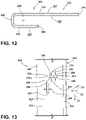
- the mounting bracket 90A is shown from a crossectional view.
- the mounting bracket 90A includes an inner wall 220 spaced-apart from an outer wall 222 with a sidewall 224 interconnecting the inner wall 220 and the outer wall 222.
- a channel 226 is defined between the inner wall 220, the outer wall 222 and the sidewall 224.
- the inner wall 220 and the outer wall 222 of the mounting bracket 90A both extend in a rearward direction from the sidewall 224, in the embodiment shown in FIG. 12 .
- a plurality of slots 230 is provided through the outer wall 222, as best shown in FIG.
- the mounting bracket 90A includes a body portion 242 having first and second ends 244, 246, such that the mounting bracket 90A is contemplated to be comprised of an extruded or roll-formed sheet metal material that is shaped into the inner wall 220, the outer wall 222 and the sidewall 224 thereof.
- the body portion 242 of the mounting bracket 90A includes upper and lower ends 250, 252, as best shown in FIG. 11 .
- the inner wall 220 and the outer wall 222 of the mounting bracket 90A are generally planar walls that run substantially parallel to one another, and include respective outer surfaces 221, 223.
- the outer surface 221 of the inner wall 220 is configured to abut the outer surface 47 of the first sidewall 46 of the external wrapper 20 of the refrigerator 10 in assembly, and is contemplated to be welded thereto to fixedly couple the mounting bracket 90A to the refrigerator 10.
- the outer surface 223 of the outer wall 222 is configured to abut the inner surface 127 of the first mounting portion 126 of the trim member 92, as further described below.
- the outer wall 222 of the mounting bracket 90A further includes an inner surface 225.
- the slot 234 of the plurality of slots 230 is shown disposed through the outer wall 222 of the mounting bracket 90A.
- the slot 234, as shown in FIG. 13 is representative of slots 236, 238 and 240, with regards to configuration.
- the slot 234 includes a first end 260 and a second end 262, which are both vertically and horizontally spaced-apart from one another.
- the first end 260 of the slot 234 includes an enlarged opening 264 which is configured to receive the head of a stud insert, as further described below.
- the enlarged opening 264 opens into a first portion 266 of the slot 234 which is generally disposed in a horizontal configuration.
- the slot 234 further includes a second portion 268 which is generally disposed in a vertical configuration, and which extends upwardly from the second end 262 towards the first portion 266 to interconnect with the first portion at a junction 266A disposed between the first and second portions 266, 268.
- the slot 234 includes an overall inverted L-shaped configuration.
- the enlarged opening 264 of the slot 234 includes a width 265 that is greater than a width 267 of the first portion 266 of the slot 234, and which is greater than a width 269 of the second portion 268 of the slot 234. It is contemplated that the widths 267 and 269 of the first and second portions 266, 268 of the slot 234 may be equal to one another.
- the widths 265, 267 and 269 of the slot 234 provide for a configuration that is suited for retaining a stud of the trim member 92 in a keyhole-style configuration, as further described below.
- the first mounting portion 126 of the trim member 92 includes a plurality of apertures 132 disposed therethrough.
- the apertures 134, 136, 138 and 140 of the plurality of apertures 132 are vertically spaced-apart along a length of the trim member 92, such that the apertures 134, 136, 138 and 140 of the trim member 92 are configured to align with the slots 234, 236, 238 and 240, respectively, of the mounting bracket 90A in assembly.
- the stud insert 270 includes a head portion 272 and a rear portion 274 with a shaft portion 276 disposed therebetween.
- the rear portion 274 may abut or be flush with the outer surface 129 of the first mounting portion 126 of the trim member 92.
- the shaft portion 276 extends inwardly from the inner surface 127 of the first mounting portion 126, such that the head portion 272 of the stud insert 270 is inwardly spaced-apart from the first mounting portion 126 of the trim member 92.
- the stud insert 270 may be welded into place, or could also be a friction fit or self-cinching member, such as a swage stud, that is fixedly disposed on the aperture 134 of the trim member 92.
- the width of the head portion 272 is greater than the width of the shaft portion 276. In this way, it is contemplated that the head portion 272 of the stud insert 270 can be received within the enlarged opening 264 of the first end 260 of the slot 234 of the mounting bracket 90A, and then abut the inner surface 225 of the outer wall 222 of the mounting bracket 90A as the stud insert 270 is moved along the first and second portions 266, 268 of the slot 234 from the first end 260 towards second end 262.
- the relative movement of the stud insert 270, and the trim member 92 to which it is attached includes an inward movement in a first direction as indicated by arrow D1 ( FIG. 13 ) to insert the head portion 272 of the stud insert 270 through the enlarged opening 264 of the first and 260 of the slot 234 of the mounting bracket 90A. From there, the stud insert 270, and the trim member 92 to which it is attached, moves rearward in the direction as indicated by arrow D2 ( FIG. 13 ) until the shaft portion 276 of the stud insert 270 reaches the junction 266A disposed between the first and second portions 266, 268 of the slot 234.
- the stud insert 270, and the trim member 92 to which it is attached moves downward in the direction as indicated by arrow D3 ( FIG. 13 ) until it reaches the second end 262 of the slot 234.
- the shaft portion 276 of the stud insert 270 disposed at the second end 262 of the slot 234 of the mounting bracket 90A
- the trim member 92 is contemplated to be in-place on the refrigerator 10, in a similar mounted configuration as shown in FIG. 3B with reference to trim member 92 of side-mounting bracket system 82.
- the engagement between the stud insert 270 and the slot 234 serves to releasably couple the trim member 92 to the mounting bracket 90A.
- the trim member 92 is shown mounted on the mounting bracket 90A. As mounted thereto, the stud insert 270 is received in the slot 234, such that the head portion 272 of the stud insert 270 abuts the inner surface 225 of the outer wall 222 of the mounting bracket 90A. In this way, the trim member 92 is retained in-place on the mounting bracket 90A, which is contemplated to be welded to the refrigerator 10. As shown in FIG. 15 , the inner surface 127 of the first mounting portion 126 of the trim member 92 abuts the outer surface 223 of the outer wall 222 of the mounting bracket 90A in assembly. Similarly, the outer surface 221 of the inner wall 220 of the mounting bracket 90A abuts the outer surface 47 of the first sidewall 46 of the refrigerator 10 in assembly.
- the refrigerator 10 is shown with another side-mounting bracket system 82B shown exploded away from the outer surface 47 of the first sidewall 46 of the refrigerator 10.
- the side-mounting bracket system 82B includes a mounting bracket 90B and trim member 92B that is contemplated to be similar to trim member 92 described above.
- the mounting bracket 90B is contemplated to be comprised of a metal material suitable for welding to the outer surface 47 of the first sidewall 46 of the refrigerator 10. Once the mounting bracket 90B is mounted on the refrigerator 10, the trim member 92B can then be mounted to the mounting bracket 90B, as further described below.
- the trim member 92B of side-mounting bracket system 82B is contemplated to connect to the cabinet structure 60 in the same manner as trim member 92 described above with reference to FIGS. 9-10 .
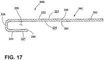
- mounting bracket 90B is shown from a crossectional view.
- Mounting bracket 90B includes a number of features in common with mounting bracket 90A described above. As such, reference numerals used to describe mounting bracket 90A will be used to describe mounting bracket 90B to indicate common features shared between mounting brackets 90A and 90B.
- the mounting bracket 90B includes an inner wall 220 spaced-apart from an outer wall 222 with a sidewall 224 interconnecting the inner wall 220 and the outer wall 222.
- a channel 226 is defined between the inner wall 220, the outer wall 222 and the sidewall 224.
- the inner wall 220 and the outer wall 222 of the mounting bracket 90B both extend in a rearward direction from the sidewall 224, in the embodiment shown in FIG. 17 .
- the mounting bracket 90B includes a body portion 242 having first and second ends 244, 246, such that the mounting bracket 90B is contemplated to be comprised of an extruded or roll-formed sheet metal material that is shaped into the inner wall 220, the outer wall 222 and the sidewall 224 thereof.
- the mounting bracket 90B includes a plurality of tabs 280 comprised of tabs 282, 284, 286 and 288 which are vertically spaced-apart from one another along a length of the body portion 242 of the mounting bracket 90B and outwardly extending from first end 246 of the mounting bracket 90B.
- Each tab 282, 284, 286 and 288 of the plurality of tabs 280 is slightly inwardly disposed relative to the outer wall 222 by a transitional portion 300.
- the body portion 242 of the mounting bracket 90B further includes upper and lower ends 250, 252, as best shown in FIG. 16 .
- the inner wall 220 and the outer wall 222 of the mounting bracket 90B are generally planar walls that run substantially parallel to one another, and include respective outer surfaces 221, 223.
- the outer surface 221 of the inner wall 220 is configured to abut the outer surface 47 of the first sidewall 46 of the external wrapper 20 of the refrigerator 10 in assembly, and is contemplated to be welded thereto to fixedly couple the mounting bracket 90B to the refrigerator 10.
- the outer surface 223 of the outer wall 222 is configured to abut the inner surface 127 of the first mounting portion 126 of the trim member 92B, as further described below.
- the tab 282 of the plurality of tabs 280 is shown rearwardly extending from the outer wall 222 of the mounting bracket 90B.
- the tab 282 is representative of tabs 284, 286 and 288 with regards to configuration.
- the tab 282 includes a body portion 302 having an upper edge 304 and a lower edge 306 to define a width 308 of the tab 282.
- the tab 282 further includes a rear edge 310 disposed adjacent to the transitional portion 300, and a front edge 312.
- the front edge 312 of the tab 282 defines a distal most end of the tab 282.
- the body portion 302 of the tab 282 includes an outer surface 303A and an inner surface 303B.
- the trim member 92B includes a plurality of slots 290 disposed therethrough.
- the slots 292, 294, 296 and 298 of the plurality of slots 290 are vertically spaced-apart along a length of the trim member 92B, such that the slots 292, 294, 296 and 298 of the trim member 92B are configured to align with the tabs 282, 284, 286 and 288, respectively, of the mounting bracket 90B. In this way, the tabs 282, 284, 286 and 288 of the mounting bracket 90B can be received through the slots 292, 294, 296 and 298 of the trim member 92B in assembly.
- the slots 292, 294, 296 and 298 of the trim member 92B include a width that is commensurate with the width 308 of the tab 282, such that the reception of the tabs 282, 284, 286 and 288 through the slots 292, 294, 296 and 298 restricts vertical movement of the trim member 92B when mounted to the mounting bracket 90B.
- the trim member 92B is shown mounted on the mounting bracket 90B, which is mounted on the refrigerator 10 at the outer surface 47 of the first sidewall 46 of the external wrapper 20.
- the tabs 282, 284, 286 and 288 of the mounting bracket 90B are shown extending through the respective slots 292, 294, 296 and 298 of the trim member 92B.
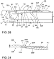
- the trim member 92B is shown mounted on the mounting bracket 90B in a cross-sectional view. As mounted thereto, the tab 282 of the mounting bracket 90B is received through the slot 292 of the trim member 92B. As further shown in FIG. 20 , the slot 292 of the trim member 92B is positioned at the inwardly angled transverse portion 185 of the trim member 92B. In this way, the inner surface 303B of the tab 282 abuts an outer surface 135 of the abutment portion 130 of the trim member 92B. As shown in FIG.
- the inner surface 127 of the first mounting portion 126 of the trim member 92B abuts the outer surface 223 of the outer wall 222 of the mounting bracket 90B in assembly.
- the outer surface 221 of the inner wall 220 of the mounting bracket 90B abuts the outer surface 47 of the first sidewall 46 of the refrigerator 10 in assembly.
- the slot 292 includes a front edge 292A and a rear edge 292B which abut the outer surface 303A and the inner surface 303B, respectively, of the body portion 302 of the tab 282 on opposite sides of the tab 282.
- This abutting engagement provides for a low tolerance fit between the mounting bracket 90B and the trim member 92B to help prevent rotational movement of the trim member 92B as mounted to the mounting bracket 90B.
- the refrigerator 10 is shown with another side-mounting bracket system 82C shown exploded away from the outer surface 47 of the first sidewall 46 of the refrigerator 10.
- the side-mounting bracket system 82C includes a mounting bracket 90C and trim member 92C that is contemplated to be similar to trim member 92B described above.
- the mounting bracket 90C is contemplated to be comprised of a metal material suitable for welding to the outer surface 47 of the first sidewall 46 of the refrigerator 10.
- the trim member 92C can then be mounted to the mounting bracket 90C, as further described below.
- the trim member 92C of side-mounting bracket system 82C connects to the cabinet structure 60 in the same manner as trim member 92 described above with reference to FIGS. 9-10 .
- mounting bracket 90C is shown from a top perspective view.
- Mounting bracket 90C includes a number of features in common with mounting bracket 90A described above. As such, reference numerals used to describe mounting bracket 90A will be used to describe mounting bracket 90C to indicate like features.
- the mounting bracket 90C includes an inner wall 220 spaced-apart from an outer wall 222 with a sidewall 224 interconnecting the inner wall 220 and the outer wall 222.
- the inner wall 220 and the outer wall 222 of the mounting bracket 90C both extend in a rearward direction from the sidewall 224, in the embodiment shown in FIG. 23 .
- a channel 226 is defined between the inner wall 220, the outer wall 222 and the sidewall 224.
- the mounting bracket 90C includes a body portion 242 having first and second ends 244, 246, such that the mounting bracket 90C is contemplated to be comprised of an extruded or roll-formed sheet metal material that is shaped into the inner wall 220, the outer wall 222 and the sidewall 224 thereof.
- the mounting bracket 90C includes a plurality of hook members 320 comprised of hook members 322, 324 and 326 which are spaced-apart from one another along a length of the body portion 242 of the mounting bracket 90C.
- Each hook member 322, 324 and 326 of the plurality of hook members 320 includes an upwardly extending tab 330 disposed over an open aperture 328 as best shown in FIG. 23 .
- the upwardly extending tab 330 is outwardly disposed relative to the outer wall 222 of the mounting bracket 90C by a transitional portion 332 to define a spacing 334 between the upwardly extending tab 330 and the outer wall 222 of the mounting bracket 90C.
- the inner wall 220 and the outer wall 222 of the mounting bracket 90C are generally planar walls that run substantially parallel to one another, and include respective outer surfaces 221, 223.
- the outer surface 221 of the inner wall 220 is configured to abut the outer surface 47 of the first sidewall 46 of the external wrapper 20 of the refrigerator 10 in assembly, and is contemplated to be welded thereto to fixedly couple the mounting bracket 90C to the refrigerator 10.
- the outer surface 223 of the outer wall 222 is configured to abut the inner surface 127 of the first mounting portion 126 of the trim member 92C, as further described below.
- the hook member 322 of the plurality of hook members 320 is representative of hook members 324 and 326 with regards to configuration.
- the upwardly extending tab 330 of hook member 322 includes a body portion 336 having an upper edge 337, and first and second side edges 338, 339. Together, the first and second side edges 338, 339 define a width 341 of the hook member 322.
- the body portion 336 of the hook member 322 includes an outer surface 337A and an inner surface 337B.
- the first mounting portion 126 of the trim member 92C includes a plurality of cutouts 340 disposed therethrough.
- the cutouts 342, 344 and 346 of the plurality of cutouts 340 are vertically spaced-apart along a length of the trim member 92C, such that the cutouts 342, 344 and 346 of the trim member 92C are configured to align with the hook members 322, 324 and 326, respectively, of the mounting bracket 90C. In this way, the hook members 322, 324 and 326 of the mounting bracket 90C can be received through the cutouts 342, 344 and 346 of the trim member 92C in assembly.
- the cutouts 342, 344 and 346 of the trim member 92C define open apertures disposed through the first mounting portion 126 of the trim member 92C.
- the cutouts 342, 344 and 346 are square-shaped cutouts, however, other shapes are contemplated for the cutouts 342, 344 and 346.
- the cutouts 342, 344 and 346 of the trim member 92C may include a width that is commensurate with the width 341 ( FIG. 23 ) of hook member 322, such that the reception of the hook members 322, 324 and 326 through the respective cutouts 342, 344 and 346 restricts lateral movement of the trim member 92C when mounted to the mounting bracket 90C.
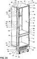
- the trim member 92C is shown mounted on the mounting bracket 90C, which is mounted on the refrigerator 10 at the outer surface 47 of the first sidewall 46 of the external wrapper 20. With the trim member 92C mounted on the mounting bracket 90C, the hook members 322, 324 and 326 of the mounting bracket 90C are shown extending through the respective cutouts 342, 344 and 346 of the trim member 92C.
- the trim member 92C is shown mounted on the mounting bracket 90C in a cross-sectional view. As mounted thereto, the hook member 322 of the mounting bracket 90C is received through the cutout 342 of the trim member 92C. As further shown in FIG. 25 , the inner surface 127 of the first mounting portion 126 of the trim member 92C abuts the outer surface 223 of the outer wall 222 of the mounting bracket 90C in assembly. Similarly, the outer surface 221 of the inner wall 220 of the mounting bracket 90C abuts the outer surface 47 of the first sidewall 46 of the refrigerator 10 in assembly.
- the refrigerator 10 is shown with another side-mounting bracket system 82D shown exploded away from the outer surface 47 of the first sidewall 46 of the refrigerator 10.
- the side-mounting bracket system 82D includes a mounting bracket 90D and a trim member 92D that is contemplated to be similar to the trim member 92C described above.
- the mounting bracket 90D is contemplated to be comprised of a metal material suitable for welding to the outer surface 47 of the first sidewall 46 of the refrigerator 10.
- the trim member 92D can then be mounted to the mounting bracket 90D, as further described below.
- the trim member 92D of side-mounting bracket system 82D connects to the cabinet structure 60 in the same manner as trim member 92 described above with reference to FIGS. 9-10 .
- mounting bracket 90D is shown from a top perspective view.
- Mounting bracket 90D includes a number of features in common with mounting bracket 90C described above. As such, reference numerals used to describe mounting bracket 90C will be used to describe mounting bracket 90D to indicate like features.
- the mounting bracket 90D includes an inner wall 220 spaced-apart from an outer wall 222 with a sidewall 224 interconnecting the inner wall 220 and the outer wall 222.
- the inner wall 220 and the outer wall 222 of the mounting bracket 90D both extend in a rearward direction from the sidewall 224, in the embodiment shown in FIG. 27 .
- a channel 226 is defined between the inner wall 220, the outer wall 222 and the sidewall 224.
- the mounting bracket 90D includes a body portion 242 having first and second ends 244, 246, such that the mounting bracket 90D is contemplated to be comprised of an extruded or roll-formed sheet metal material that is shaped into the inner wall 220, the outer wall 222 and the sidewall 224 thereof.
- the mounting bracket 90D includes a plurality of mounting flanges 350 comprised of mounting flanges 352, 354 and 356 which are vertically spaced-apart from one another along a length of the body portion 242 of the mounting bracket 90D.
- Each mounting flange 352, 354 and 356 of the plurality of mounting flanges 350 includes an outwardly extending tab 360 disposed over an open aperture 358 as best shown in FIG. 27 .
- the outwardly extending tab 360 is outwardly disposed relative to the outer wall 222 of the mounting bracket 90D by upper and lower transitional portions 362, 364 to define a spacing 366 between the outwardly extending tab 360 and the outer wall 222 of the mounting bracket 90D.
- the inner wall 220 and the outer wall 222 of the mounting bracket 90D are generally planar walls that run substantially parallel to one another, and include respective outer surfaces 221, 223.
- the outer surface 221 of the inner wall 220 is configured to abut the outer surface 47 of the first sidewall 46 of the external wrapper 20 of the refrigerator 10 in assembly, and is contemplated to be welded thereto to fixedly couple the mounting bracket 90D to the refrigerator 10.
- the outer surface 223 of the outer wall 222 is configured to abut the inner surface 127 of the first mounting portion 126 of the trim member 92D, as further described below.
- the mounting flange 352 of the plurality of mounting flanges 350 as shown in FIG.
- FIG. 27 is representative of mounting flanges 354 and 356 with regards to configuration.
- the outwardly extending tab 360 of mounting flange 352 includes a body portion 370 having side edges 372, 374 to define a width 376 of the mounting flange 352.
- the first mounting portion 126 of the trim member 92D includes a plurality of cutouts 380 disposed therethrough.
- the cutouts 382, 384 and 386 of the plurality of cutouts 380 are vertically spaced-apart along a length of the trim member 92D, such that the cutouts 382, 384 and 386 of the trim member 92D are configured to align with the mounting flanges 352, 354 and 356, respectively, of the mounting bracket 90D. In this way, the mounting flanges 352, 354 and 356 of the mounting bracket 90D can be received through the cutouts 382, 384 and 386 of the trim member 92D in assembly.
- the cutouts 382, 384 and 386 define open apertures disposed through the first mounting portion 126 of the trim member 92D.
- the cutouts 382, 384 and 386 are square shaped cutouts, however, other shapes are contemplated for the cutouts 382, 384 and 386.
- the cutouts 382, 384 and 386 of the trim member 92D may include a width that is commensurate with the width 376 of mounting flange 352, such that the reception of the mounting flanges 352, 354 and 356 through the cutouts 382, 384 and 386 restricts lateral movement of the trim member 92D when mounted to the mounting bracket 90D.
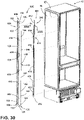
- the trim member 92D is shown mounted on the mounting bracket 90D, which is mounted on the refrigerator 10 at the outer surface 47 of the first sidewall 46 of the external wrapper 20.
- the mounting flanges 352, 354 and 356 of the mounting bracket 90D are shown extending through the respective cutouts 382, 384 and 386 of the trim member 92D.
- the trim member 92D is shown mounted on the mounting bracket 90D in a cross-sectional view. As mounted thereto, the mounting flange 352 of the mounting bracket 90D is received through the cutout 382 of the trim member 92D.
- the inner surface 127 of the first mounting portion 126 of the trim member 92D is contemplated to abut the outer surface 223 of the outer wall 222 of the mounting bracket 90D in assembly, and the outer surface 221 of the inner wall 220 of the mounting bracket 90D is contemplated to abut the outer surface 47 of the first sidewall 46 of the refrigerator 10 in assembly.
- the refrigerator 10 is shown with another side-mounting bracket system 82E shown exploded away from the outer surface 47 of the first sidewall 46 of the refrigerator 10.
- the side-mounting bracket system 82E includes a mounting bracket 90E and trim member 92 that is contemplated to be similar, if not identical, to trim member 92 described above with reference to FIGS. 3A and 3B .
- the mounting bracket 90E is contemplated to be comprised of a metal material suitable for welding to the outer surface 47 of the first sidewall 46 of the refrigerator 10. Once the mounting bracket 90E is mounted on the refrigerator 10, the trim member 92 can then be mounted to the mounting bracket 90E, as further described below.
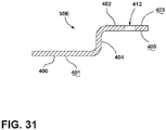
- the mounting bracket 90E is shown from a cross-sectional view.
- the mounting bracket 90E includes an inner wall 400 spaced-apart from an outer wall 402 with an intermediate wall 404 interconnecting the inner wall 400 and the outer wall 402.
- the inner wall 400 projects in a forward direction relative to the intermediate wall 404, while the outer wall 402 projects in a rearward direction relative to the intermediate wall 404.
- the outer wall 402 is outwardly offset relative to the inner wall 400 by the intermediate wall 404.
- the mounting bracket 90E is contemplated to be comprised of an extruded or roll-formed sheet metal material that is shaped into the inner wall 400, the outer wall 402 and the intermediate wall 404 thereof.
- the inner wall 400 and the outer wall 402 of the mounting bracket 90E are generally planar walls that run substantially parallel to one another, and include respective outer surfaces 401, 403.
- the outer surface 401 of the inner wall 400 is configured to abut the outer surface 47 of the first sidewall 46 of the external wrapper 20 of the refrigerator 10 in assembly, and is contemplated to be welded thereto to fixedly couple the mounting bracket 90E to the refrigerator 10.
- the outer surface 403 of the outer wall 402 is configured to abut the inner surface 127 of the first mounting portion 126 of the trim member 92, as further described below.
- the outer wall 402 further includes an inner surface 405.
- the mounting bracket 90E includes a plurality of apertures 410 extending along a length thereof in a vertically spaced-apart relationship.
- the plurality of apertures 410 of the mounting bracket 90E includes apertures 412, 414, 416, 418, 420 and 422 that are vertically spaced-apart from one another.
- the first mounting portion 126 of the trim member 92 includes a plurality of apertures 430 extending along a length thereof in a vertically spaced-apart relationship.
- the plurality of apertures 430 of the trim member 92 includes apertures 432, 434, 436, 438, 440 and 442 that are vertically spaced-apart from one another.
- the apertures 432, 434, 436, 438, 440 and 442 of the trim member 92 are configured to align with the apertures 412, 414, 416, 418, 420 and 422, respectively, of the mounting bracket 90E to define aligned mounting apertures therebetween. Further, the apertures 412, 414, 416, 418, 420 and 422 of the plurality of apertures 410 of the mounting bracket 90E are contemplated to have threaded inserts coupled thereto, much like threaded insert 200 described above.
- the trim member 92 is shown mounted on the mounting bracket 90E, which is mounted on the refrigerator 10 at the outer surface 47 of the first sidewall 46 of the external wrapper 20.
- the apertures 432, 434, 436, 438, 440 and 442 of the trim member 92 are accessible and configured to receive fasteners therethrough to secure the trim member 92 to the mounting bracket 90E.
- the trim member 92 is shown mounted on the mounting bracket 90E in a cross-sectional view.
- aperture 412 of the mounting bracket 90E aligns with aperture 432 of the trim member 92 to define a first set of aligned apertures 412A, therebetween.
- Fastener 204 having a head portion 206 and a threaded shaft portion 208, is configured to be received in the aligned apertures 412A.
- the threaded insert 200 is shown mounted to aperture 412 of the mounting bracket 90E.
- the threaded shaft portion 208 of fastener 204 is contemplated to have a complimentary thread pattern relative to the threaded inner cavity 202 of the threaded insert 200 to threadingly engage the same, thereby securely fastening the trim member 92 to the mounting bracket 92E.
- the inner surface 127 of the first mounting portion 126 of the trim member 92 abuts the outer surface 403 of the outer wall 402 of the mounting bracket 90E in assembly, and the outer surface 401 of the inner wall 400 of the mounting bracket 90E abuts the outer surface 47 of the first sidewall 46 of the refrigerator 10, as welded thereto.
- any number of apertures, mounting apertures, cutouts, slots, hook members, tabs and the like may be used to mount a trim member to a mounting bracket for use with the present concept.
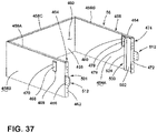
- the machine room cover 56 is shown having a body portion 450 comprised of first and second sidewalls 452, 454 with a rear wall 456 interconnecting the first and second sidewalls 452, 454 to form a generally U-shaped configuration surrounding a cavity 460.
- the first sidewall 452 includes inner and outer surfaces 452A, 452B.
- the second sidewall 454 includes inner and outer surfaces 454A, 454B.
- An inwardly extending flange 458 includes first and second portions 458A, 458B extending along upper portions of the first and second sidewalls 452, 454, and a third portion 458C extending along an upper portion of the rear wall 456.
- the first sidewall 452 includes an inwardly turned front flange 462 extending inwardly from the inner surface 452A of the first sidewall 452 into the cavity 460.
- a plurality of apertures 464 are disposed through the front flange 462 along with a slot 466 that is vertically disposed along the front flange 462.
- the plurality of apertures 464 includes sets of apertures disposed above and below the slot 466.
- the first sidewall 452 further includes the mounting aperture 468 that is configured to align with an aperture of a trim member to couple the same thereto. As shown in FIGS.
- the lower mounting aperture 168 of the first mounting portion 126 of the trim member 92 aligns with mounting aperture 468 of the machine room cover 56 for mounting the lower end 158 of the trim member 92 to the machine room cover 56 using a fastener.
- the mounting aperture 468 is disposed on a tab 470 that downwardly extends over an aperture 469 and outwardly extends from the outer surface 452B of the first sidewall 452.
- the second sidewall 454 includes an inwardly turned front flange 472 extending inwardly from the inner surface 454A of the second sidewall 454 into the cavity 460.
- a plurality of apertures 474 are disposed through the front flange 472 of the second sidewall 454, along with a slot 476 that is vertically disposed along the front flange 462 of the second sidewall 454.
- the plurality of apertures 464 includes sets of apertures disposed above and below the slot 466.
- the second sidewall 454 further includes a mounting aperture 478 that is configured to align with an aperture of a trim member to couple the same thereto in manner as described above with reference to mounting aperture 468 of the first sidewall 452.
- the second trim member 92A ( FIG. 3B ) also includes a lower mounting aperture for coupling a lower end of the second trim member 92A to the mounting aperture 478 of the second sidewall 454 of the machine room cover 56.
- the mounting aperture 478 is disposed on a tab 480 that downwardly extends over an aperture 479 and outwardly extends from the outer surface 454B of the second sidewall 454.
- the plurality of apertures 464 of the front flange 462 of the first sidewall 452 and the plurality of apertures 464 of the front flange 462 of the second sidewall 454 are provided to secure lower braces to the machine room cover 56, as further described below.
- a brace member 500 is shown, and is contemplated to be a lower brace member for securing the machine room cover 56 to the cabinet structure 60.
- the brace member 500 includes a body portion 502 having inner and outer surfaces 502A, 502B.
- the brace member 500 further includes upper and lower front flanges 508, 510 disposed on a front portion 504 of the body portion 502.
- the upper and lower front flanges 508, 510 are vertically spaced-apart from one another to define first and second flanges with an outwardly extending tab 512 disposed therebetween.
- the upper front flange 508 extends inwardly from the inner surface 502A of the body portion 502, and includes a plurality of apertures 509 disposed therethrough.
- the plurality of apertures 509 disposed through the upper front flange 508 includes three spaced-apart apertures.
- the lower front flange 510 extends inwardly from the inner surface 502A of the body portion 502, and includes a plurality of apertures 511 disposed therethrough.
- the plurality of apertures 511 disposed through the lower front flange 510 includes two spaced-apart apertures.
- the outwardly extending tab 512 is an extension of the body portion 502 of the brace member 500 and includes the inner and outer surfaces 502A, 502B discussed above.
- the outwardly extending tab 512 further includes a front edge 514 and upper and lower edges 516, 518 that are spaced-apart from one another to define a width 520 of the outwardly extending tab 512.
- the outwardly extending tab 512 further includes a plurality of apertures 522 disposed therethrough. In the embodiment shown in FIGS. 35 and 36 , the plurality of apertures 522 includes six apertures evenly spaced-apart along the outwardly extending tab 512.
- the brace member 500 further includes a rear flange 524 which inwardly extends from the inner surface 502A of the body portion 502 at a rear portion 506 thereof, as best shown in FIG. 36 .
- the machine room cover 56 is shown having the brace member 500 coupled to the second sidewall 454 thereof.
- the body portion 502 of the brace member 500 is positioned against the inner surface 454A of the second sidewall 454.
- the outwardly extending tab 512 of the brace member 500 is shown extending through the slot 476 disposed along the front flange 474 of the machine room cover 56.
- the plurality of apertures 522 of the outwardly extending tab 512 are accessible for mounting the brace member 500 to the cabinet structure 60 using fasteners.
- the brace member 500 is contemplated to be mounted to the inner surface 69 of the second sidewall 68 of the cabinet structure 60. As further shown in FIG.
- a second brace member 501 is shown coupled to the first sidewall 452 of the machine room cover 56.
- the second brace member 501 is contemplated to be a mirror image of the brace member 500 described above, and is configured to be mounted to the inner surface 67 of the first sidewall 66 of the cabinet structure 60. In this way the brace members 500, 501 secure the refrigerator 10 to the opposed first and second sidewalls 66, 68 of the cabinet structure 60 at the machine room cover 56 of the refrigerator 10 using fasteners, as shown with respect to brace member 500 in FIG. 3C .
- a roller box assembly 550 is shown in an exploded view.
- the roller box assembly 550 is used to support the refrigerator 10 in a rolling capacity, as shown in FIG. 3C .
- the roller box assembly 550 includes first and second housing assemblies 552, 554.
- the first housing assembly 552 includes an inner wall 556, an outer wall 558, a front wall 560 and rear wall 562 which cooperate together to define an interior cavity 564.
- the interior cavity 564 is contemplated to house one or more wheel assemblies, such that a refrigerator supported on the roller box assembly 550 can be wheeled to a destination, such as the cabinet enclosure 80 of the cabinet structure 60 described above.
- the outer wall 558 of the first housing assembly 552 includes a forward extending tab 566 having an aperture 568 disposed therethrough. As shown in FIG. 38 , the forward extending tab 566 extends forward of the front wall 560, such that the forward extending tab 566, and the aperture 568 thereof, are accessible for mounting to a sidewall of the cabinet structure 60.
- the second housing assembly 554 includes an inner wall 570, an outer wall 572, a front wall 574 and rear wall 576 which cooperate together to define an interior cavity 578. In use, the interior cavity 578, much like interior cavity 564 of the first housing assembly 552, is contemplated to house one or more wheel assemblies to further support a refrigerator in a rolling manner.
- the outer wall 558 of the second housing assembly 554 includes a forward extending tab 580 having an aperture 582 disposed therethrough.
- the forward extending tab 580 extends forward of the front wall 574, such that the forward extending tab 580, and the aperture 582 thereof, are accessible for mounting to a sidewall of the cabinet structure 60, using a fastener.
- the roller box assembly 550 is configured to couple to the opposing first and second sidewalls 66, 68 of the cabinet structure 60 at the respective inner surfaces 67, 69 thereof, as shown in FIGS. 1 and 2 .
- the outer walls 558 and 572 of the first and second housing assemblies 552, 554 are disposed adjacent to the inner surfaces 67, 69 of the first and second sidewalls 66, 68 of the cabinet structure 60, when the refrigerator 10 is positioned therein.
- a fastener can be used at the respective apertures 568, 582 of the first and second housing assemblies 552, 554 for securely mounting the same to the cabinet structure 60.
- the roller box assembly 550 restricts fore and aft movement of a refrigerator assembly housed within the cabinet structure 60.
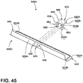
- the roller box assembly 550 includes a bottom plate 590 having a body portion 592 that is used to interconnect the first and second housing assemblies 552, 554.
- the body portion 592 of the bottom plate 590 includes upper and lower surfaces 592A, 592B.
- the bottom plate 590 further includes opposed first and second side edges 593, 595 having respective apertures 594, 596 disposed therethrough for mounting to the first and second housing assemblies 552, 554 to the upper surface 592A of the bottom plate 590.
- the bottom plate 590 further includes a front edge 598 with an anchor bracket 600 disposed thereon.
- the anchor bracket 600 includes first and second portions 602, 604.
- the first portion 602 of the anchor bracket 600 downwardly extends from the lower surface 592B, as best shown in FIG. 39 .
- the second portion 604 of the anchor bracket 600 outwardly extends in a forward direction from the first portion 602, as best shown in FIG. 39 .
- the second portion 604 of the anchor bracket 600 is substantially parallel with the body portion 592 of the bottom plate 590 as extending outward in an orthogonal direction relative to the first portion 602 of the anchor bracket 600.
- mounting apertures 608 Disposed along a front edge 606 of the second portion 604 of the anchor bracket 600 mounting apertures 608 are positioned therealong and are configured to mount the bottom plate 590 to the inner surface 65 of the bottom wall 64 of the cabinet structure 60 in assembly.
- an outer surface 600B of the anchor bracket 600 of the bottom plate 590 is configured to abut the inner surface 65 ( FIG. 1 ) of the bottom wall 64 of the cabinet structure 60 in assembly.
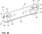
- the roller box assembly 550 includes a front bracket 610 having opposed side edges 612, 614 having respective apertures 613, 615 for mounting the front bracket 610 to the front walls 560, 574 of the first and second housing assemblies 552, 554.
- the front bracket 610 also serves to interconnect the first and second housing assemblies 552, 554 of the roller box assembly 550.
- the front bracket 610 further includes an upper edge 616 with the rearwardly extending flange 618 which is contemplated to couple to a top wall of the roller box assembly 550 in assembly.
- the front bracket 610 is shown having a rearwardly extending flange 622 that extends rearwardly from the bottom edge 620 of the front bracket 610.
- the rearwardly extending flange 622 includes a relief portion 624 disposed in a middle portion thereof to define first and second tabs 626, 628 disposed on either sides of the relief portion 624.
- the relief portion 624 is a cutout portion of the rearwardly extending flange 622 which is configured to receive the second portion 604 of the anchor bracket 600 of the bottom plate 590 therethrough. This configuration is best shown in FIGS. 41 and 42 . In FIGS.
- the roller box assembly 550 is shown in an assembled condition with the first and second housing assemblies 552, 554 disposed on the opposite side edges 593, 595 of the bottom plate 590.
- the anchor bracket 600 of the bottom plate 590 is shown having the second portion 604 thereof extending outwardly through the relief portion 624 of the front bracket 610, such that the second portion 604 of the anchor bracket 600 of the bottom plate 590 is accessible for mounting to the cabinet structure 60 at the bottom wall 64 thereof.
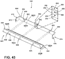
- an upper bracket system 648 is shown with a hinge bracket 650 having a first portion 652 and a second portion 654.
- the first portion 652 of the hinge bracket 650 is a substantially horizontal portion that includes upper and lower surfaces 652A, 652B.
- the second portion 654 of the hinge bracket 650 is a substantially upright portion that extends orthogonally in an upright direction from the upper surface 652A of the first portion 652 of the hinge bracket 650.
- the second portion 654 of the hinge bracket 650 includes front and rear surfaces 654A, 654B.
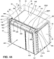
- the hinge bracket 650 includes an overall L-shaped configuration between the first and second portions 652, 654, and is contemplated to be comprised of a metal material suitable for welding the first portion 652 of the hinge bracket 650 to the outer surface 43 of the top wall 42 of the vacuum insulated cabinet structure 12 of the refrigerator 10, as best shown in FIG. 44 .
- the upper bracket system 648 is mounted between the refrigerator 10 and the cabinet structure 60.
- the lower surface 652B of the first portion 652 of the hinge bracket 650 abuts the outer surface 43 of the top wall 42 of the refrigerator 10 in assembly, and may be fixedly coupled thereto, as further described below.
- the hinge bracket 650 may be used to mount one or more hinges thereto for use in operating doors positioned on the refrigerator 10 to selectively provide access to refrigerated storage compartments.
- the hinge bracket 650 includes a plurality of apertures 656 disposed along the second portion 654 of the hinge bracket 650.
- the plurality of apertures 656 shown in the embodiment of the hinge bracket 650 in FIG. 43 includes three sets of apertures 658 for a total of six apertures, altogether.
- the upper bracket system 648 includes a mounting bracket 660 having a body portion 662 with opposed first and second ends 664, 666.
- the body portion 662 of the mounting bracket 660 is positioned in a generally upright manner and includes front and rear surfaces 660A, 660B.
- the first end 664 of the mounting bracket 660 includes a first side bracket 670 extending orthogonally in a forward direction from the front surface 660A of the mounting bracket 660.
- the first side bracket 670 includes a plurality of apertures 672 which, in the embodiment of FIG. 43 includes four spaced-apart apertures.
- the second end 666 of the mounting bracket 660 also includes a second side bracket 674 extending orthogonally in a forward direction from the front surface 660A of the mounting bracket 660.
- the second side bracket 674 also includes a plurality of apertures 676 which, in the embodiment of FIG. 43 includes four spaced-apart apertures.
- the apertures provided in the plurality of apertures 672, 676 of the first and second side brackets 670, 674 are used to couple the mounting bracket 660 to the opposed first and second sidewalls 66, 68 of the cabinet structure 60 at the respective inner surfaces 67, 69 thereof, as best shown in FIG. 44 .
- FIG. 44 In the embodiment shown in FIG.
- the mounting bracket 660 includes a plurality of mounting apertures 680 disposed along the body portion 662 of the mounting bracket 660.
- the plurality of mounting apertures 680 shown in the embodiment of the mounting bracket 660 in FIG. 43 includes three sets of mounting apertures 682 for a total of six apertures, altogether.
- the plurality of mounting apertures 680 of the mounting bracket 660 are provided in a reciprocal pattern relative to the plurality of apertures 656 of the hinge bracket 650. In this way, the plurality of mounting apertures 680 of the mounting bracket 660 can be aligned with the plurality of apertures 656 of the hinge bracket 650 for interconnecting the mounting bracket 660 and the hinge bracket 650.
- the apertures 658 of the plurality of apertures 656 of the hinge bracket 650 are contemplated to be through apertures that will allow for a threaded shaft of a fastener to pass through.
- the mounting apertures 682 of the plurality of mounting apertures 680 are contemplated to receive a threaded insert 200 having a threaded inner cavity 202, in a similar manner as described above.
- a suitable fastener can be used to couple to the threaded insert 200 in a threaded engagement to fixedly couple the component parts together.
- apertures identified with reference numeral 682, and pluralities of the same identified with reference numeral 680 are contemplated to be mounting apertures fitted with a threaded insert, in a manner as described above with reference to threaded insert 200.
- apertures identified with reference numeral 658, and pluralities of the same identified with reference numeral 656, are contemplated to be through apertures, allowing for fastener shafts to pass therethrough, in a manner as described above.
- the cabinet structure 60 is shown in phantom to reveal the mounting bracket 660 mounted to the inner surfaces 67, 69 of the opposed first and second sidewalls 66, 68.
- the mounting bracket 660 is mounted to the inner surfaces 67, 69 of the opposed first and second sidewalls 66, 68 of the cabinet structure 60 at the first and second side brackets 670, 674 of the mounting bracket 660.
- the trim members 92, 92A are shown mounted to the opposed first and second sidewalls 46, 48 of the refrigerator 10.
- the trim members 92, 92A each include upper ends 156 having cutout portions 157. As shown in FIG.
- the first and second side brackets 670, 674 of the mounting bracket 660 are aligned with the cutout portions 157 of the trim members 92, 92A, such that the respective apertures provided in the plurality of apertures 672, 676 of the first and second side brackets 670, 674 can be used to couple the mounting bracket 660 to the inner surfaces 67, 69 of the opposed first and second sidewalls 66, 68 of the cabinet structure 60.
- the first portion 652 of the hinge bracket 650 is shown abutting the outer surface 43 of the top wall 42 of the refrigerator 10.
- the rear surface 654B of the second portion 654 of the hinge bracket 650 is shown as abutting the front surface 660A of the mounting bracket 660 in the arrangement of FIG. 44 .
- the plurality of mounting apertures 680 of the mounting bracket 660 are aligned with the plurality of apertures 656 of the hinge bracket 650 ( FIG. 44 ) for interconnecting the mounting bracket 660 and the hinge bracket 650 using fasteners.
- the mounting bracket 660 is mounted to the opposed first and second sidewalls 66, 68 of the cabinet structure 60, before the refrigerator 10 is inserted into the cabinet enclosure 80 of the cabinet structure 60.
- the hinge bracket 650 may be welded, or otherwise fixedly coupled, to the top wall 42 of the refrigerator 10, before the refrigerator 10 is inserted into the cabinet enclosure 80 of the cabinet structure 60.
- the hinge bracket 650 may be positioned on the outer surface 43 of the top wall 42 of the refrigerator 10, such that the lower surface 652B of the first portion 652 of the hinge bracket 650 abuts the outer surface 43 of the top wall 42 of the refrigerator 10, without the need to fixedly couple the hinge bracket 650 thereto.
- the refrigerator 10 can be inserted into the cabinet enclosure 80 of the cabinet structure 60 in the direction as indicated by arrow 685 in FIG. 44 until the rear surface 654B of the hinge bracket 650 abuts the front surface 660A of the mounting bracket 660.
- the plurality of mounting apertures 680 of the mounting bracket 660 are contemplated to be aligned with the plurality of apertures 656 of the hinge bracket 650 for threaded engagement with the threaded inserts provided in the mounting apertures 680 of the plurality of mounting apertures 682 of the mounting bracket 660.
- fasteners can be used to fixedly couple the hinge bracket 650 to the mounting bracket 660 while the hinge bracket 650 is supported on the refrigerator 10, and the mounting bracket 660 is fixedly coupled to the cabinet structure 60.
- an upper bracket system 648A is shown with a hinge bracket 650A which includes a number of features in common with the hinge bracket 650 described above. As such, like reference numerals are used in FIG. 45 to identify common features shared between the hinge brackets 650 and 650A.
- the plurality of apertures 656 are disposed on the second portion 694 of the hinge bracket 650A and are clustered in a middle portion thereof.
- the plurality of apertures 656 shown in the embodiment of the hinge bracket 650A in FIG. 45 includes two sets of spaced-apart apertures 658 for a total of four apertures, altogether.
- the upper bracket system 648A includes a mounting bracket 690, wherein the mounting bracket 690 includes first and second portions 692, 694.
- the first portion 692 of the mounting bracket 690 is a substantially horizontal portion that includes upper and lower surfaces 692A, 692B.
- the second portion 694 of the mounting bracket 690 is a substantially vertical portion that extends orthogonally in a downward direction from the lower surface 692B of the first portion 692 of the mounting bracket 690.
- the second portion 694 of the mounting bracket 690 includes front and rear surfaces 694A, 694B.
- the mounting bracket 690 includes an overall L-shaped configuration between the first and second portions 692, 694 thereof, and is contemplated to be comprised of a metal material.
- the first portion 692 of the mounting bracket 690 includes a plurality of apertures 696 which, in the embodiment of FIG. 45 includes five spaced-apart apertures.
- the apertures provided in the plurality of apertures 696 of the first portion 692 of the mounting bracket 690 are used to couple the mounting bracket 690 to the top wall 62 of the cabinet structure 60 at the inner surface 63 thereof, as best shown in FIG. 46 .
- the mounting bracket 690 includes a plurality of mounting apertures 680 disposed along the second portion 694 of the mounting bracket 690.
- the 45 includes two sets of mounting apertures 682 for a total of four apertures, altogether.
- the plurality of mounting apertures 680 of the mounting bracket 690 are provided in a reciprocal pattern relative to the plurality of apertures 656 of the hinge bracket 650A. In this way, the plurality of mounting apertures 680 of the mounting bracket 690 can be aligned with the plurality of apertures 656 of the hinge bracket 650A for interconnecting the mounting bracket 690 and the hinge bracket 650A in assembly.
- the cabinet structure 60 is shown in phantom to reveal the upper bracket system 648A mounted between the refrigerator 10 and the cabinet structure 60.
- the mounting bracket 690 is mounted to the inner surface 63 of the top wall 62 of the cabinet structure 60.
- the mounting bracket 690 is mounted to the inner surface 63 of the top wall 62 of the cabinet structure 60 at the first portion 692 of the mounting bracket 690.
- the upper surface 692A of the first portion 692 of the mounting bracket 690 is configured to abut the inner surface 63 of the top wall 62 of the cabinet structure 60, such that the plurality of apertures 696 can be used to fasten the mounting bracket 690 thereto.
- FIG. 46 the cabinet structure 60 is shown in phantom to reveal the upper bracket system 648A mounted between the refrigerator 10 and the cabinet structure 60.
- the mounting bracket 690 is mounted to the inner surface 63 of the top wall 62 of the cabinet structure 60.
- the mounting bracket 690 is mounted to the inner surface 63 of the top wall 62 of the cabinet structure 60 at
- the hinge bracket 650A is shown positioned on the outer surface 43 of the top wall 42 of the refrigerator 10 at the first portion 652 thereof.
- the rear surface 654B of the hinge bracket 650A is contemplated to be abutting the front surface 694A ( FIG. 45 ) of the mounting bracket 690 in the arrangement of FIG. 46 .
- the plurality of mounting apertures 680 ( FIG. 45 ) of the mounting bracket 690 are aligned with the plurality of apertures 656 of the hinge bracket 650A for interconnecting the mounting bracket 690 and the hinge bracket 650A using fasteners.
- the mounting bracket 690 is mounted to the top wall 62 of the cabinet structure 60, before the refrigerator 10 is inserted into the cabinet enclosure 80 of the cabinet structure 60.
- the hinge bracket 650A may be welded, or otherwise fixedly coupled, to the top wall 42 of the refrigerator 10, before the refrigerator 10 is inserted into the cabinet enclosure 80 of the cabinet structure 60.
- the hinge bracket 650A may be positioned on the outer surface 43 of the top wall 42 of the refrigerator 10, such that the lower surface 652B of the first portion 652 of the hinge bracket 650A abuts the outer surface 43 of the top wall 42 of the refrigerator 10, without the need to fixedly couple the hinge bracket 650A thereto.
- the refrigerator 10 can be inserted into the cabinet enclosure 80 of the cabinet structure 60 in the direction as indicated by arrow 685 in FIG. 46 until the rear surface 654B of the hinge bracket 650A abuts the front surface 694A of the mounting bracket 690.
- the plurality of mounting apertures 680 of the mounting bracket 690 are aligned with the plurality of apertures 656 of the hinge bracket 650A for threaded engagement with the threaded inserts provided in the mounting apertures 680 of the plurality of mounting apertures 682 of the mounting bracket 690.
- fasteners can be used to fixedly couple the hinge bracket 650A to the mounting bracket 690 while the hinge bracket 650A is supported on the refrigerator 10, and the mounting bracket 690 is fixedly coupled to the cabinet structure 60.
- an upper bracket system 648B is shown with a hinge bracket 650B having a number of features in common with hinge brackets 650 and 650A described above. As such, like reference numerals are used in FIG. 47 to denote common features shared between the hinge brackets 650, 650A and 650B.
- a plurality of apertures 656 are disposed on the second portion 694 of the hinge bracket 650B and are clustered in a middle portion thereof.
- the plurality of apertures 656 shown in the embodiment of the hinge bracket 650B in FIG. 47 includes three sets of spaced-apart apertures 658 for a total of six apertures, altogether.
- the upper bracket system 648B includes a mounting bracket 690A shown exploded away from the hinge bracket 650B, and having a number of features in common with mounting bracket 690 described above. As such, like reference numerals are used in FIG. 47 to denote common features shared between the mounting brackets 690 and 690A.
- the first portion 692 of the mounting bracket 690A includes a plurality of apertures 696 which, in the embodiment of FIG. 47 includes five spaced-apart apertures.
- the apertures provided in the plurality of apertures 696 of the first portion 692 of the mounting bracket 690A are used to couple the mounting bracket 690A to the top wall 62 of the cabinet structure 60 at the inner surface 63 thereof, as best shown in FIG. 48 .
- the mounting bracket 690A further includes a plurality of mounting apertures 680 disposed along the second portion 694 of the mounting bracket 690A.
- the plurality of mounting apertures 680 shown in the embodiment of the mounting bracket 690A in FIG. 47 includes three sets of mounting apertures 682 for a total of six apertures, altogether.
- the plurality of mounting apertures 680 of the mounting bracket 690A are provided in a reciprocal pattern relative to the plurality of apertures 656 of the hinge bracket 650B. In this way, the plurality of mounting apertures 680 of the mounting bracket 690A can be aligned with the plurality of apertures 656 of the hinge bracket 650B for interconnecting the mounting bracket 690A and the hinge bracket 650B in assembly.
- the hinge bracket 650B also includes a plurality of apertures 656A disposed on a first end 655 of the second portion 654 of the hinge bracket 650B.
- the plurality of apertures 656A includes a number of apertures 658A, which may be in the form of round apertures or oblong-shaped slots, or any combination thereof.
- the plurality of apertures 656A is used to mount a first hinge support bracket 700 to the hinge bracket 650A, as further described below.
- the hinge bracket 650B further includes a plurality of apertures 656B disposed on a second end 657 of the second portion 654 of the hinge bracket 650B.
- the second end 657 of the second portion 654 of the hinge bracket 650B is contemplated to be an opposite or opposed end relative to the first end 655 of the second portion 654 of the hinge bracket 650B.
- the plurality of apertures 656 disposed at the middle portion of the second portion 654 of the hinge bracket 650B is disposed between the plurality of apertures 656A, 656B which are disposed at the first and second ends 655, 657, respectively, of the second portion 654 of the hinge bracket 650B.
- the plurality of apertures 656B includes a number of apertures 658B, which may be in the form of round apertures or oblong-shaped slots, or any combination thereof.
- the plurality of apertures 656B is used to mount a second hinge support bracket 701 to the hinge bracket 650A, as further described below.
- first and second hinge support brackets 700, 701 are shown exploded away from the hinge bracket 650B.
- the first and second hinge support brackets 700, 701 are contemplated to be mirror images of each other, such that like reference numerals will be used to describe common features between the first and second hinge support brackets 700, 701. Further, the description of one hinge support bracket provided herein also describes the other reciprocal hinge support bracket.
- the first and second hinge support brackets 700, 701 each include a first portion 702 and a second portion 704.
- the first portion 702 of the first and second hinge support brackets 700, 701 is a substantially horizontal portion that includes upper and lower surfaces 702A, 702B.
- the second portion 704 of the first and second hinge support brackets 700, 701 is a substantially upright portion that extends orthogonally in an upright direction from the upper surface 702A of the first portion 702 of the first and second hinge support brackets 700, 701.
- the second portion 704 of the first and second hinge support brackets 700, 701 includes front and rear surfaces 704A, 704B.
- the first and second hinge support brackets 700, 701 each include a third portion 706 extending outwardly in a forward direction from the front surface 704A of the second portion 704 of the first and second hinge support brackets 700, 701.
- the third portion 706 includes an upper surface 706A and a lower surface 706B. As shown in FIG.
- the third portion 706 extends outwardly from an upper portion of the second portion 704 of the first and second hinge support brackets 700, 701, while the first portion 702 extends rearwardly from a lower portion of the second portion 704 of the first and second hinge support brackets 700, 701.
- the first portion 702 is vertically offset from, but substantially parallel to, the third portion 706.
- the second portion 704 of the first and second hinge support bracket 700, 701 is substantially perpendicular to both the first portion 702 and the third portion 706.
- the first and second hinge support brackets 700, 701 each include an overall S-shaped configuration between the first, second and third portions 702, 704 and 706 thereof.
- the second hinge support bracket 701 is shown having an inner sidewall 708 and an outer sidewall 710.
- the inner sidewall 708 and outer sidewall 710 are disposed in a substantially upright position and spaced-apart from each other on opposite sides of the first and second portions 702, 704 of the second hinge support bracket 701.
- the inner sidewall 708 and the outer sidewall 710 interconnect the first and second portions 702, 704 of the second hinge support bracket 701 to provide a bracing feature therebetween.
- the lower surface 702B of the second hinge support bracket 701 is configured to abut the upper surface 652A of the first portion 652 of the hinge bracket 650B, as best shown in FIG. 49 .
- FIG. 49 In FIG.
- the first portion 702 is shown having one or more apertures 712 which can be used to mount the second hinge support bracket 701 to the first portion 652 of the hinge bracket 650B, at the upper surface 652A thereof.
- the second portion 704 of the second hinge support bracket 701 is shown having a plurality of apertures 714 which can be used to mount the second hinge support bracket 701 to the second portion 654 of the hinge bracket 650B, at the plurality of apertures 656B of the hinge bracket 650B.
- the plurality of apertures 714 illustrated in FIG. 48 are shown in phantom, as they are covered by the third portion 706 of the second hinge support bracket 701.
- the plurality of apertures 714 of the second hinge support bracket 701 are contemplated to be disposed in a reciprocal pattern relative to the plurality of apertures 656B disposed on the hinge bracket 650B. In this way, it is contemplated that the front surface 704A of the second portion 704 of the second hinge support bracket 701 is configured to abut the rear surface 654B of the second portion 654 of the hinge bracket 650B in assembly, as best shown in FIG. 49 .
- the third portion 706 of the second hinge support bracket 701 includes first and second mounting flanges 720, 722 which are disposed over respective apertures 721, 723.
- the first and second mounting flanges 720, 722 include similar features, such that the description of the first mounting flange 720 will describe the second mounting flange 722 as well.
- the first mounting flange 720 includes a tab portion 724 that is vertically spaced-apart from the upper surface 706A of the third portion 706 by an angled portion 726. Specifically, the angled portion 726 extends upwardly at a forward angle from the upper surface 706A of the third portion 706 of the second hinge support bracket 701.
- the tab portion 724 is contemplated to be vertically spaced-apart, but substantially planar with the upper surface 706A of the third portion 706 of the second hinge support bracket 701.
- Apertures 728 define one or more apertures disposed through the tab portion 724, and are used to couple the second hinge support bracket 701 to the top wall 62 of the cabinet structure 60 at the inner surface 63 thereof, as best shown in FIG. 49 .
- the second hinge support bracket 701 further includes a side mounting flange 730 disposed adjacent to the outer sidewall 710.
- the side mounting flange 730 includes a first tab portion 732 that is inwardly spaced-apart from a second tab portion 734 by a transverse portion 736. Said differently, the second tab portion 734 of the side mounting flange 730 is spaced outwardly relative to the first tab portion 732.
- the first and second tab portions 732, 734 are disposed below the third portion 706 of the second hinge support bracket 701, and are substantially perpendicular thereto.
- the first tab portion 732 of the side mounting flange 730 includes one or more apertures 738 disposed therethrough.
- the one or more apertures 738 of the first tab portion 732 of the side mounting flange 730 may be used to couple the second hinge support bracket 701 to an upper end of a trim member, such as the upper end 156 of trim member 92A at upper mounting aperture 166 shown in FIG. 49 .
- the second tab portion 734 of the side mounting flange 730 also includes one or more apertures 740 disposed therethrough.
- the one or more apertures 740 of the second tab portion 734 of the side mounting flange 730 may be used to couple the second hinge support bracket 701 to a sidewall of the cabinet structure, such as the second sidewall 68 of the cabinet structure 60 at the inner surface 69 thereof, as best shown in FIG. 49 .
- the upper bracket system 648B is shown mounted between the refrigerator 10 and the cabinet structure 60.
- the cabinet structure 60 is shown in phantom to reveal the mounting bracket 690A mounted to the inner surface 63 of the top wall 62 of the cabinet structure 60.
- the mounting bracket 690A is mounted to the inner surface 63 of the top wall 62 of the cabinet structure 60 at the first portion 692 of the mounting bracket 690A.
- the upper surface 692A of the first portion 692 of the mounting bracket 690A is configured to abut the inner surface 63 of the top wall 62 of the cabinet structure 60, such that the plurality of apertures 696 can be used to fasten the mounting bracket 690A thereto.
- the hinge bracket 650B is shown positioned on the outer surface 43 of the top wall 42 of the refrigerator 10 at the first portion 652 thereof.
- the rear surface 654B of the hinge bracket 650B abuts the front surface 694A of the mounting bracket 690A in the arrangement of FIG. 49 .
- the plurality of mounting apertures 680 ( FIG. 47 ) of the mounting bracket 690A are aligned with the plurality of apertures 656 of the hinge bracket 650B for interconnecting the mounting bracket 690A and the hinge bracket 650B using fasteners. It is contemplated that the mounting bracket 690A is mounted to the top wall 62 of the cabinet structure 60, before the refrigerator 10 is inserted into the cabinet enclosure 80 of the cabinet structure 60.
- the hinge bracket 650B may be welded, or otherwise fixedly coupled, to the top wall 42 of the refrigerator 10, before the refrigerator 10 is inserted into the cabinet enclosure 80 of the cabinet structure 60. Further, it is contemplated that the hinge bracket 650B may be positioned on the outer surface 43 of the top wall 42 of the refrigerator 10, such that the lower surface 652B of the first portion 652 of the hinge bracket 650B abuts the outer surface 43 of the top wall 42 of the refrigerator 10, without the need to fixedly couple the hinge bracket 650B thereto.
- the refrigerator 10 can be inserted into the cabinet enclosure 80 of the cabinet structure 60 in the direction as indicated by arrow 685 in FIG. 49 until the rear surface 654B of the hinge bracket 650B abuts the front surface 694A of the mounting bracket 690A.
- this abutting arrangement is provided between the rear surface 654B of the hinge bracket 650B and the front surface 694A of the mounting bracket 690A, the plurality of mounting apertures 680 ( FIG.
- the mounting bracket 690A are aligned with the plurality of apertures 656 of the hinge bracket 650B for threaded engagement with the threaded inserts provided in the mounting apertures 680 of the plurality of mounting apertures 682 of the mounting bracket 690.
- fasteners can be used to fixedly couple the hinge bracket 650B to the mounting bracket 690A while the hinge bracket 650B is supported on the refrigerator 10, and the mounting bracket 690A is fixedly coupled to the cabinet structure 60.
- first and second hinge support brackets 700, 701 are shown coupled to the hinge bracket 650B. Specifically, the lower surfaces 702B of the first portions 702 of the first and second hinge support brackets 700, 701 abut the upper surface 652A of the first portion 652 of the hinge bracket 650B. Further, the front surfaces 704A ( FIG. 48 ) of the second portions 704 of the first and second hinge support brackets 700, 701 abut the rear surface 654B of the second portion 654 of the hinge bracket 650B.
- the first and second mounting flanges 720, 722 of the first and second hinge support brackets 700, 701 are shown upwardly extending from the third portions 706 of the first and second hinge support brackets 700, 701, such that the apertures 728 thereof can be used to couple the first and second hinge support brackets 700, 701 to the top wall 62 of the cabinet structure 60 at the inner surface 63 thereof.
- the first tab portions 732 of the side mounting flanges 730 have apertures 738 ( FIG. 48 ) accessible to couple the first and second hinge support brackets 700, 701 to the upper ends 156 of the first and second trim members 92 and 92A.
- the one or more apertures 740 ( FIG. 48 ) of the second tab portions 734 of the side mounting flanges 730 are aligned with the cutout portions 157 of the first and second trim members 92 and 92A, such that the one or more apertures 740 thereof are accessible to couple the first and second hinge support brackets 700, 701 to the first and second sidewalls 66, 68, respectively, at the respective inner surfaces 67, 69 thereof.
- an upper bracket system 648C is shown having another embodiment of a hinge bracket 650C.
- the hinge bracket 650C includes body portion 800 having a first portion 802, a second portion 804 and a third portion 806.
- the first portion 802 of the hinge bracket 650C is a substantially horizontal portion that includes upper and lower surfaces 802A, 802B.
- the second portion 804 of the hinge bracket 650C is a substantially upright portion that extends orthogonally in an upright direction from the upper surface 802A of the first portion 802 of the hinge bracket 650C.
- the second portion 804 of the hinge bracket 650C includes a front surface 804A ( FIG. 51 ) and a rear surface 804B ( FIG. 50 ).
- the third portion 806 of the hinge bracket 650C extends outwardly in a forward direction from the front surface 804A of the second portion 804 of the hinge bracket 650C.
- the third portion 806 of the hinge bracket 650C includes an upper surface 806A and a lower surface 806B. As shown in FIGS. 50 and 51 , the third portion 806 extends outwardly from an upper portion of the second portion 804 of the hinge bracket 650C, while the first portion 802 extends rearwardly from a lower portion of the second portion 804 of the hinge bracket 650C. Thus, the first portion 802 is vertically offset from, but substantially parallel to, the third portion 806.
- the second portion 804 of the hinge bracket 650C is substantially perpendicular to both the first portion 802 and the third portion 806. In this way, the hinge bracket 650C includes an overall S-shaped configuration between the first, second and third portions 802, 804 and 806 thereof.
- the lower surface 802B of hinge bracket 650C is configured to abut the outer surface 43 of the top wall of the refrigerator 10, as best shown in FIG. 52 .
- first portion 802 of the hinge bracket 650C is shown having first and second sets of apertures 812, 813 that can be used to mount first and second hinge support brackets 700A, 701A ( FIG. 50 ) to opposed sides of the first portion 802 of the hinge bracket 650C, at the upper surface 802A thereof.
- the second portion 804 of hinge bracket 650C is shown having a number of sets of apertures similar to the configuration of apertures found on the second portion 654 of the hinge bracket 650B discussed above.
- like reference numerals used to describe the aperture arrangement and other features of the second portion 654 of the hinge bracket 650B discussed above will also be used to describe apertures and features of the second portion 802 of the hinge bracket 650C.
- a plurality of apertures 656A is disposed on the first end 655 of the second portion 802 of the hinge bracket 650C and is used to mount a first hinge support bracket 700A ( FIG. 50 ) to the hinge bracket 650C, as further described below.
- the hinge bracket 650C further includes a plurality of apertures 656B disposed on a second end 657 of the second portion 802 of the hinge bracket 650C.
- the plurality of apertures 656B is used to mount a second hinge support bracket 701A ( FIG. 50 ) to the hinge bracket 650C, as further described below.
- the second end 657 of the second portion 802 of the hinge bracket 650C is contemplated to be an opposite or opposed end relative to the first end 655 of the second portion 802 of the hinge bracket 650C.
- a plurality of apertures 656 is disposed at the middle portion of the second portion 802 of the hinge bracket 650C between the plurality of apertures 656A, 656B, and is configured to mount the second portion 802 of the hinge bracket 650C to the mounting bracket 690A ( FIG. 50 ).
- the plurality of apertures 656 shown in the embodiment of the hinge bracket 650C in FIGS. 50 and 51 includes three sets of spaced-apart apertures 658 for a total of six apertures, altogether.
- the mounting bracket 690A is shown exploded away from the hinge bracket 650C.
- the first portion 692 of the mounting bracket 690A includes the plurality of apertures 696 which, in the embodiment of FIG. 50 includes five spaced-apart apertures for coupling the mounting bracket 690A to the top wall 62 of the cabinet structure 60 at the inner surface 63 thereof, as best shown in FIG. 52 .
- the mounting bracket 690A further includes the plurality of mounting apertures 680 disposed along the second portion 694 of the mounting bracket 690A in a reciprocal pattern relative to the plurality of apertures 656 of the hinge bracket 650C. In this way, the plurality of mounting apertures 680 of the mounting bracket 690A can be aligned with the plurality of apertures 656 of the hinge bracket 650C for interconnecting the mounting bracket 690A and the hinge bracket 650C in assembly.
- first and second hinge support brackets 700A, 701A are shown exploded away from the hinge bracket 650B.
- the first and second hinge support brackets 700A, 701A are contemplated to be mirror images of each other, and are also contemplated to include a number of features in common with first and second hinge support brackets 700, 701 described above. As such, like reference numerals will be used to describe common features between the first and second hinge support brackets 700, 701 and the first and second hinge support brackets 700A, 701A.
- the first and second hinge support brackets 700A, 701A each include a first portion 702 having upper and lower surfaces 702A, 702B, and a second portion 704 having front and rear surfaces 704A, 704B.
- the first portion 702 of the first and second hinge support brackets 700A, 701A is substantially perpendicular to the second portion 704. Inner and outer sidewalls 708, 710 interconnect the first and second portions 702, 704.
- the first portion 702 of the first hinge support bracket 700A includes apertures 712 that are configured to couple to apertures 812 of the hinge bracket 650C to mount the first hinge support bracket 700A to the first portion 802 of the hinge bracket 650C.
- the first portion 702 of the second hinge support bracket 701A includes apertures 712 that are configured to couple to apertures 813 of the hinge bracket 650C to mount the second hinge support bracket 701A to the first portion 802 of the hinge bracket 650C.
- the second portion 704 of the first hinge support bracket 700A includes apertures 714 that are configured to couple to apertures 656A of the hinge bracket 650C to mount the first hinge support bracket 700A to the second portion 804 of the hinge bracket 650C.
- the second portion 704 of the second hinge support bracket 701A includes apertures 714 that are configured to couple to apertures 656B of the hinge bracket 650C to mount the second hinge support bracket 701A to the second portion 804 of the hinge bracket 650C.
- the third portion 806 of hinge bracket 650C includes first, second and third mounting flanges 818, 820 and 822 which are disposed over respective apertures 819, 821 and 823.
- the mounting flanges 818, 820 and 822 include similar features, such that the description of the first mounting flange 818 will describe the second and third mounting flanges 820, 822 as well.
- the first mounting flange 818 includes a tab portion 824 that is vertically spaced-apart from the upper surface 806A of the third portion 806 by an angled portion 826. Specifically, the angled portion 826 extends upwardly at a forward angle from the upper surface 806A of the third portion 806 of hinge bracket 650C.
- the tab portion 824 is contemplated to be vertically spaced-apart, but substantially planar with the upper surface 806A of the third portion 806 of hinge bracket 650C.
- Apertures 828 define one or more apertures disposed through the tab portion 824 of the first mounting flange 818, and are used to couple the hinge bracket 650C to the top wall 62 of the cabinet structure 60 at the inner surface 63 thereof, as best shown in FIG. 52 .
- the hinge bracket 650C further includes first and second side mounting flanges 830 disposed adjacent to the outer sidewall 810.
- the first and second side mounting flanges 830, 831 each include a first tab portion 832 that is inwardly spaced-apart from a second tab portion 834.
- the second tab portion 834 of the first and second side mounting flanges 830, 831 is spaced outwardly relative to the first tab portion 832.
- the first and second tab portions 832, 834 are disposed below the third portion 806 of hinge bracket 650C, and are substantially perpendicular thereto.
- the first tab portion 832 of the first and second side mounting flanges 830, 831 each include one or more apertures 838 disposed therethrough.
- the one or more apertures 838 of the first tab portion 832 of the first and second side mounting flanges 830, 831 may be used to couple the hinge bracket 650C to an upper end of a trim member, such as the upper end 156 of trim member 92A at upper mounting aperture 166 shown in FIG. 52 .
- the second tab portion 834 of the first and second side mounting flanges 830, 831 also includes one or more apertures 840 disposed therethrough.
- the one or more apertures 840 of the second tab portion 834 of the first and second side mounting flanges 830, 831 may be used to couple the hinge bracket 650C to a sidewall of the cabinet structure, such as the first and second sidewalls 66, 68 of the cabinet structure 60 at the respective inner surfaces 67, 69 thereof, as best shown in FIG. 52 .
- an upper bracket system 648D is shown having another embodiment of a hinge bracket 650D.
- the hinge bracket 650D is similar to hinge bracket 650C, but does not include the first portion 802 of hinge bracket 650C. Instead, the hinge bracket 650D includes a body portion 800 having a first portion 803 and a second portion 805. The first portion 803 and the second portion 805 of the hinge bracket 650D are akin to the second portion 804 and the third portion 806 of hinge bracket 650C, respectively. Otherwise, like reference numerals are provided in FIG. 53 to denote common features shared between hinge brackets 650C and 650D.
- the first portion 803 of the hinge bracket 650D is a substantially upright portion that includes a front surface 803A and a rear surface 803B.
- the second portion 805 of the hinge bracket 650D extends outwardly in a forward direction from the front surface 804A of the first portion 803 of the hinge bracket 650D.
- the second portion 805 of the hinge bracket 650D is a substantially horizontal portion that includes an upper surface 805A and a lower surface 805B. As shown in FIG. 53 , the second portion 805 of the hinge bracket 650D extends outwardly from an upper portion of the first portion 803 of the hinge bracket 650D, such that the first portion 803 of the hinge bracket 650D is substantially perpendicular to the second portion 805.
- the hinge bracket 650D includes an overall L-shaped configuration between the first and second portions 803, 805 thereof.
- a plurality of apertures 656 is disposed at the middle portion of the first portion 803 of the hinge bracket 650D, and is configured to mount the first portion 803 of the hinge bracket 650D to the plurality of apertures 680 of the second portion 694 of the mounting bracket 690A.
- the plurality of apertures 656 shown in the embodiment of the hinge bracket 650D in FIG. 53 includes three sets of spaced-apart apertures 658 for a total of six apertures, which corresponds to the six mounting apertures 682 of the plurality of apertures 680 disposed on the second portion 694 of the mounting bracket 690A.
- first portion 692 the mounting bracket 690A couples to the top wall 62 of the cabinet structure 60, while the second portion 694 of the mounting bracket 690A mounts to the first portion 803 of the hinge bracket 650D.
- the one or more apertures 840 of the second tab portion 834 of the first and second side mounting flanges 830, 831 may be used to couple the hinge bracket 650C to a sidewall of the cabinet structure, such as the first and second sidewalls 66, 68 of the cabinet structure 60 at the respective inner surfaces 67, 69 thereof.
- the hinge bracket 650E includes a body portion 850 having a first portion 852, a second portion 854 and a third portion 856.
- the first portion 852 of the hinge bracket 650E is a substantially horizontal portion that includes upper and lower surfaces 852A, 852B.
- the second portion 854 of the hinge bracket 650E is a substantially upright portion that extends orthogonally in an upright direction from the upper surface 852A of the first portion 852 of the hinge bracket 650E.
- the second portion 854 of the hinge bracket 650E includes a front surface 854A ( FIG. 56 ) and a rear surface 854B.
- the third portion 856 of the hinge bracket 650E extends outwardly in a forward direction from the front surface 854A of the second portion 854 of the hinge bracket 650E.
- the third portion 856 of the hinge bracket 650E includes an upper surface 856A. As shown in FIG. 54 , the third portion 856 extends outwardly from an upper portion of the second portion 854 of the hinge bracket 650E, while the first portion 852 extends rearwardly from a lower portion of the second portion 854 of the hinge bracket 650E. Thus, the first portion 852 is vertically offset from, but substantially parallel to, the third portion 856.
- the second portion 854 of the hinge bracket 650E is substantially perpendicular to both the first portion 852 and the third portion 856.
- the hinge bracket 650E includes an overall S-shaped configuration between the first, second and third portions 852, 854 and 856 thereof.
- the lower surface 852B of hinge bracket 650E is configured to abut the outer surface 43 of the top wall of the refrigerator 10, as best shown in FIG. 56 .
- the hinge bracket 650E includes first and second sidewalls 862, 864 disposed on opposite sides of the body portion 850.
- the first sidewall 862 includes a plurality of apertures 866 disposed therethrough.
- the apertures of the plurality of apertures 866 of the first sidewall 862 are configured to couple the hinge bracket 650E to a mounting bracket 880 ( FIG. 55 ), as further described below.
- the second sidewall 864 includes a plurality of apertures 868 disposed therethrough.
- the apertures of the plurality of apertures 868 of the second sidewall 864 are also configured to couple the hinge bracket 650E to a mounting bracket 880 ( FIG. 55 ), as further described below.
- FIG. 55 In the embodiment shown in FIG.
- the hinge bracket 650E includes a plurality of braces 870, 872 and 874 which are configured in a generally triangular shape, and which interconnect the first second and third portions 852, 854 and 856 of the hinge bracket 650E to provide a reinforcement feature for the hinge bracket 650E.
- the mounting bracket 880 includes a first portion 882 and a second portion 884.
- the first portion 882 of the mounting bracket 880 includes a generally planar body portion 886 having first and second downwardly turned end walls 888, 890.
- the second downwardly turned end wall 890 includes a plurality of apertures 892.
- the plurality of apertures 892 are shown in a configuration similar to the plurality of apertures 868 disposed on the second sidewall 864 of the hinge bracket 650E, as shown in FIG. 54 .
- a plurality of apertures is disposed on the first downwardly turned end wall 888 of the mounting bracket 880 as well, that is similar in configuration to the plurality of apertures 892 of the second downwardly turned end wall 890.
- the plurality of apertures disposed on the first downwardly turned end wall 888 of the mounting bracket 880 is similar in configuration to the plurality of apertures 866 disposed on the first sidewall 862 of the hinge bracket 650E, as shown in FIG. 54 .
- the body portion 886 and the first and second downwardly turned end walls 888, 890 of the first portion 882 of the mounting bracket 880 provide for an overall inverted U-shaped configuration for the first portion 882 of the mounting bracket 880.
- the first portion 882 of the mounting bracket 880 is configured to be received over the third portion 856 of the hinge bracket 650E, such that the body portion 886 of the first portion 882 of the mounting bracket 880 abuts the upper surface 856A of the third portion 856 of the hinge bracket 650E when the mounting bracket 880 is coupled thereto.
- the first and second downwardly turned ends 888, 890 are contemplated to be aligned with the respective first and second sidewalls 862, 864 of the hinge bracket 650E, such that the apertures thereof are aligned and ready for coupling to one another.
- the upper bracket system 648E is shown mounted between the refrigerator 10 and the cabinet structure 60.
- the second portion 884 of the mounting bracket 880 includes a generally planar body portion 896 having first and second downwardly turned end walls 898, 900.
- the first and second downwardly turned end walls 898, 900 each include a plurality of apertures 902, 904, respectively.
- the plurality of apertures 902 and 904 of the first and second downwardly turned end walls 898, 900 are provided to receive fasteners therethrough to couple the first and second downwardly turned end walls 898, 900 to the opposed side walls 66, 68 of the cabinet structure 60 at the respective inner surfaces 67, 69 thereof, as best shown in FIG. 56 .
- the body portion 896 and the first and second downwardly turned end walls 898, 900 of the second portion 884 of the mounting bracket 880 provide for an overall inverted U-shaped configuration for the second portion 884 of the mounting bracket 880. While the second portion 884 of the mounting bracket 880 includes a similar configuration to the first portion 882 of the mounting bracket 880, the second portion 884 of the mounting bracket 880 is provided with the body portion 896 thereof in a forward and upward position relative to the body portion 886 of the first portion 882 of the mounting bracket 880. Further, the body portion 896 of the second portion 884 of the mounting bracket 880 is longer than the body portion 886 of the first portion 882 of the mounting bracket 880.
- the first and second downwardly turned end walls 898, 900 are positioned both forward and outward relative to the first and second downwardly turned end walls 888, 890 of the first portion 882 of the mounting bracket 880, respectively.
- the body portion 896 of the second portion 884 of the mounting bracket 880 includes apertures 897 disposed therethrough along a front edge 899 of the body portion 896.
- the second portion 884 of the mounting bracket 880 is configured to abut the inner surface 63 of the top wall 62 of the cabinet structure 60, such that the apertures 897 are accessible for mounting the mounting bracket 880 to the top wall 62 of the cabinet structure 60.
- the refrigerator 10 With the mounting bracket 880 coupled to the top wall 62 of the cabinet structure 60, and the first portion 852 of the hinge bracket 650E supported on the top wall 42 of the refrigerator 10, the refrigerator 10 can be inserted into the cabinet enclosure 80 of the cabinet structure 60 until the first and second sidewalls 862, 864, and the respective apertures 866, 868 thereof, of the hinge bracket 650E are aligned with the first and second downwardly turned end walls 888, 890, and the respective apertures thereof, of the first portion 882 of the mounting bracket 880 and configured for coupling to one another using fasteners.
- a hinge bracket 650F is shown having a number of features in common with hinge bracket 650 described above. As such, like reference numerals are used in FIGS. 57 and 58 to identify common features shared between the hinge brackets 650 and 650F.
- the hinge bracket 650F defines another upper bracket system 648F of the present concept.
- the hinge bracket 650F includes a first portion 652 and a second portion 654.
- the first portion 652 of the hinge bracket 650F is a substantially horizontal portion that includes an upper surface ( FIG. 57 ) and a lower surface 652B ( FIG. 58 ).
- the second portion 654 of the hinge bracket 650F is a substantially upright portion that extends orthogonally in an upright direction from the upper surface 652A of the first portion 652 of the hinge bracket 650F.
- the second portion 654 of the hinge bracket 650 includes front and rear surfaces 654A, 654B.
- the hinge bracket 650F includes an overall L-shaped configuration between the first and second portions 652, 654 thereof.
- the first portion 652 of the hinge bracket 650F includes first and second ends 910, 912 that are opposed to one another.
- a first side bracket 914 is positioned on the first end 910 in a substantially upright manner.
- the first side bracket 914 is substantially perpendicular to both the first and second portions 652, 654 of the hinge bracket 650F, and includes inner and outer surfaces 914A, 914B.
- the first side bracket 914 includes a plurality of apertures 916 disposed therethrough. In the embodiment shown in FIGS. 57 and 58 , the plurality of apertures 916 includes three pairs of spaced-apart apertures for a total of six apertures altogether.
- the outer surface 914B of the first side bracket 914 is configured to abut the inner surface 67 of the first sidewall 66 of the cabinet structure 60 when the hinge bracket 650F is positioned on the top wall 42 of the refrigerator 10 and received within the cabinet enclosure 80 of the cabinet structure 60. In this way, the plurality of apertures 916 of the first side bracket 914 are accessible for coupling the first side bracket 914 to the first sidewall 66 of the cabinet structure 60 using fasteners.
- a second side bracket 918 is positioned on the first end 910 in a substantially upright manner.
- the second side bracket 918 is substantially perpendicular to both the first and second portions 652, 654 of the hinge bracket 650F, and includes inner and outer surfaces 918A, 918B.
- the second side bracket 918 includes a plurality of apertures 920 disposed therethrough.
- the plurality of apertures 920 includes three pairs of spaced-apart apertures for a total of six apertures altogether.
- the outer surface 918B of the second side bracket 918 is configured to abut the inner surface 69 of the second sidewall 68 of the cabinet structure 60 when the hinge bracket 650F is positioned on the top wall 42 of the refrigerator 10 and received within the cabinet enclosure 80 of the cabinet structure 60.
- the plurality of apertures 920 of the second side bracket 918 are accessible for coupling the second side bracket 918 to the second sidewall 68 of the cabinet structure 60 using fasteners.
- the first portion 652 of the hinge bracket 650F includes first and second sets of apertures 921, 922 which may be used to couple the hinge support brackets, such as first and second hinge support brackets 700, 701 described above, to the hinge bracket 650F.
- FIGS. 59 and 60 another embodiment of a hinge bracket 650G is shown having a number of features in common with hinge bracket 650F. As such, like reference numerals are used to identify common features between hinge brackets 650F and 650G.
- the hinge bracket 650G defines another upper bracket system 648G of the present concept.
- the hinge bracket 650G includes a third portion 930.
- the third portion 930 of the hinge bracket 650G extends outwardly in a forward direction from the front surface 654A ( FIG. 60 ) of the second portion 654 of the hinge bracket 650G.
- the third portion 930 of the hinge bracket 650G includes an upper surface 930A and a lower surface 930B.
- the third portion 930 of the hinge bracket 650G extends outwardly from an upper portion of the second portion 654 of the hinge bracket 650G, while the first portion 652 extends rearwardly from a lower portion of the second portion 654 of the hinge bracket 650G.
- the first portion 652 is vertically offset from, but substantially parallel to, the third portion 930.
- the second portion 654 of the hinge bracket 650G is substantially perpendicular to both the first portion 652 and the third portion 930. In this way, the hinge bracket 650G includes an overall S-shaped configuration between the first, second and third portions 652, 654 and 930 thereof.
- the third portion 930 of hinge bracket 650G includes first, second and third mounting flanges 932, 934 and 936 which are disposed over respective apertures 933, 935 and 937.
- the mounting flanges 932, 934 and 936 include similar features, such that the description of the third mounting flange 936 will describe the first and second mounting flanges 932, 934 as well.
- the third mounting flange 936 includes a tab portion 940 that is vertically spaced-apart from the upper surface 930A of the third portion 930 by an angled portion 942.
- the angled portion 942 extends upwardly at a forward angle from the upper surface 930A of the third portion 930 of hinge bracket 650G.
- the tab portion 824 is contemplated to be vertically spaced-apart, but substantially planar with the upper surface 930A of the third portion 930 of hinge bracket 650G.
- Apertures 944 define one or more apertures disposed through the tab portion 940 of the third mounting flange 936, and are used to couple the hinge bracket 650G to the top wall 62 of the cabinet structure 60 at the inner surface 63 thereof.
- the first, second and third mounting flanges 932, 934 and 936 are similar in configuration and function to mounting flanges 818, 820 and 822 described above with reference to FIGS.
- the hinge bracket 650G may also be provided in another embodiment, wherein the first and second side brackets 914, 918 thereof are removed from the hinge bracket 650G.
- any combination of side-mounting bracket systems such as side-mounting bracket systems 82-82E discussed above, and upper bracket systems, such as upper bracket systems 648-648E discussed above, can be used together to couple a refrigerator to a cabinet structure.
- any lower mounting system such as the roller box assembly 550 and machine room cover 56 and braces 500, 501, can be used with the above mentioned systems.
- a bracket system for use between an outer surface of an appliance and an inner surface of a cabinet structure includes a mounting bracket with an inner wall spaced-apart from an outer wall with at least one sidewall that interconnects the inner wall and the outer wall.
- a channel is defined between the inner wall and the outer wall.
- a plurality of apertures is provided through the outer wall. Each aperture of the plurality of apertures opens into the channel.
- the inner wall is configured to abut the outer surface of the appliance.
- a trim member includes first and second mounting portions and an abutment portion inwardly offset from the first and second mounting portions.
- the first mounting portion includes a plurality of apertures disposed therethrough.
- One or more of the apertures of the plurality of apertures of the first mounting portion of the trim member align with one or more of the apertures of the plurality of apertures of the mounting bracket to define aligned mounting apertures therebetween.
- An inner surface of the first mounting portion abuts the outer wall of the mounting bracket and a portion of an inner surface of the abutment portion is configured to abut the outer surface of the appliance.
- the second mounting portion includes a plurality of apertures disposed therethrough. An outer surface of the second mounting portion is configured to abut the inner surface of the cabinet structure.
- the at least one sidewall of the mounting bracket defines a first sidewall, and a second sidewall extends outwardly from the inner wall of the mounting bracket towards the outer wall of the mounting bracket.
- the second sidewall includes a distal end spaced-apart from the outer wall of the mounting bracket to define an opening into the channel of the mounting bracket.
- one or more apertures of the plurality of apertures provided through the outer wall of the mounting bracket include a threaded insert coupled thereto.
- a fastener is received in one or more of the aligned mounting apertures and threadingly engaged with the threaded insert.
- the first mounting portion includes a body portion having a thickness that is less than a thickness of a body portion of the second mounting portion and less than a thickness of a body portion of the abutment portion.
- the second mounting portion includes a tab inwardly extending from an inner surface of the second mounting portion.
- the trim member includes an inwardly angled transverse portion disposed between the first mounting portion and the abutment portion.
- an inner surface of the abutment portion includes first and second abutment locations configured to abut the outer surface of the appliance with an outwardly extending interconnecting web disposed between the first and second abutment locations.
- a bracket system for use between an outer surface of an appliance and an inner surface of a cabinet structure includes a mounting bracket with an inner wall spaced-apart from an outer wall with an intermediate wall interconnecting the inner wall and the outer wall.
- the inner wall is configured to abut the outer surface of the appliance, and a plurality of apertures is provided through the outer wall.
- a trim member includes a front mounting portion and a rear mounting portion spaced-apart from one another along a body portion of the trim member.
- the front and rear mounting portions each include a plurality of apertures disposed therethrough.
- One or more of the apertures of the plurality of apertures of the rear mounting portion of the trim member align with one or more of the apertures of the plurality of apertures of the mounting bracket to define aligned mounting apertures therebetween.
- An inner surface of the rear mounting portion abuts the outer wall of the mounting bracket.
- An outer surface of the front mounting portion is configured to abut the inner surface of the cabinet structure.
- the apertures of the plurality of apertures provided through the outer wall of the mounting bracket include a threaded insert coupled thereto.
- a fastener is received in one or more of the aligned mounting apertures and threadingly engaged with the threaded insert.
- the plurality of apertures of the front mounting portion are disposed adjacent to a front edge of the trim member and vertically spaced-apart therealong.
- an appliance mounting system includes an appliance having a sidewall with an outer surface.
- a mounting bracket includes an inner wall spaced-apart from an outer wall. The outer wall includes a plurality of apertures provided therethrough. The inner wall is coupled to the outer surface of the sidewall of the appliance.
- a trim member includes first and second mounting portions. The first mounting portion and the second mounting portion each include a plurality of apertures disposed therethrough. One or more of the apertures of the plurality of apertures of the first mounting portion of the trim member align with one or more of the apertures of the plurality of apertures of the mounting bracket to define aligned mounting apertures therebetween. An inner surface of the first mounting portion abuts the outer wall of the mounting bracket.
- a cabinet structure includes a sidewall with an inner surface to at least partially define a cabinet enclosure. The appliance is received within the cabinet enclosure of the cabinet structure. An outer surface of the second mounting portion of the trim member abuts the inner surface of the sidewall of the cabinet structure.
- one or more apertures of the plurality of apertures provided through the outer wall of the mounting bracket include a threaded insert coupled thereto.
- a fastener is received in one or more of the aligned mounting apertures and threadingly engaged with the threaded insert.
- a fastener is received in one or more of the apertures of the plurality of apertures of the second mounting portion of the trim member to couple the trim member to the sidewall of the cabinet structure.
- the appliance includes a vacuum insulated cabinet structure having an external wrapper comprised of a metal material.
- the mounting bracket is welded to the external wrapper.
- the vacuum insulated cabinet structure includes a vacuum cavity positioned between the external wrapper and one or more liners.
- the vacuum cavity includes a negative internal pressure.
- the trim member includes an abutment portion inwardly offset from the first and second mounting portions. A portion of an inner surface of the abutment portion abuts the outer surface of the side wall of the appliance.
- a bracket system for use between an outer surface of an appliance and an inner surface of a cabinet structure includes a mounting bracket having an inner wall spaced-apart from an outer wall with at least one sidewall interconnecting the inner wall and the outer wall.
- a channel is defined between the inner wall and the outer wall.
- a plurality of apertures is provided through the outer wall. Each aperture of the plurality of apertures opens into the channel.
- the inner wall is configured to abut the outer surface of the appliance.
- a trim member includes first and second mounting portions and an abutment portion inwardly offset from the first and second mounting portions.
- the first mounting portion includes a plurality of apertures disposed therethrough.
- One or more of the apertures of the plurality of apertures of the first mounting portion of the trim member align with one or more of the apertures of the plurality of apertures of the mounting bracket.
- An inner surface of the first mounting portion abuts the outer wall of the mounting bracket and an inner surface of the abutment portion is configured to abut the outer surface of the appliance.
- An outer surface of the second mounting portion is configured to abut the inner surface of the cabinet structure.
- At least one sidewall of the mounting bracket includes first and second sidewalls.
- the second sidewall extends outwardly from the inner wall of the mounting bracket towards the outer wall of the mounting bracket.
- the second sidewall of the mounting bracket includes a distal end that is spaced-apart from the outer wall of the mounting bracket to define an opening into the channel of the mounting bracket.
- the one or more apertures of the plurality of apertures provided through the outer wall of the mounting bracket includes a threaded insert coupled thereto.
- a fastener is received through the one or more apertures of the plurality of apertures of the first mounting portion of the trim member, such that the fastener threadingly engages the threaded insert.
- the first mounting portion includes a body portion having a thickness that is less than a thickness of a body portion of the second mounting portion.
- the thickness of the body portion of the first mounting portion is less than a thickness of a body portion of the abutment portion.
- the second mounting portion includes a tab inwardly extending from an inner surface of the second mounting portion.
- the tab includes a distal end configured to abut the outer surface of the appliance.
- the trim member includes an inwardly angled transverse portion disposed between the first mounting portion and the abutment portion.
- an inner surface of the abutment portion includes first and second abutment locations that are configured to abut the outer surface of the appliance with an outwardly extending interconnecting web disposed between the first and second abutment locations.
- the second mounting portion includes a plurality of apertures disposed therethrough.
- a fastener is received in one or more of the apertures of the plurality of apertures of the second mounting portion of the trim member to couple the trim member to the inner surface of a cabinet structure.
- the appliance includes a vacuum insulated cabinet structure having an external wrapper comprised of a metal material.
- the mounting bracket is welded to the external wrapper.
- the vacuum insulated cabinet structure includes a vacuum cavity having a negative internal pressure.
Landscapes
- Engineering & Computer Science (AREA)
- Chemical & Material Sciences (AREA)
- Combustion & Propulsion (AREA)
- Physics & Mathematics (AREA)
- Mechanical Engineering (AREA)
- Thermal Sciences (AREA)
- General Engineering & Computer Science (AREA)
- Life Sciences & Earth Sciences (AREA)
- Sustainable Development (AREA)
- Refrigerator Housings (AREA)
- Housings, Intake/Discharge, And Installation Of Fluid Heaters (AREA)
Abstract
Description
- The present disclosure generally relates to a bracket system for an appliance, and more specifically, to a bracket system for mounting an appliance to a cabinet structure.
- According to one aspect of the present disclosure, a bracket system for use between an outer surface of an appliance and an inner surface of a cabinet structure includes a mounting bracket with an inner wall spaced-apart from an outer wall with at least one sidewall that interconnects the inner wall and the outer wall. A channel is defined between the inner wall and the outer wall. A plurality of apertures is provided through the outer wall. Each aperture of the plurality of apertures opens into the channel. The inner wall is configured to abut the outer surface of the appliance. A trim member includes first and second mounting portions and an abutment portion inwardly offset from the first and second mounting portions. The first mounting portion includes a plurality of apertures disposed therethrough. One or more of the apertures of the plurality of apertures of the first mounting portion of the trim member align with one or more of the apertures of the plurality of apertures of the mounting bracket to define aligned mounting apertures therebetween. An inner surface of the first mounting portion abuts the outer wall of the mounting bracket and a portion of an inner surface of the abutment portion is configured to abut the outer surface of the appliance. The second mounting portion includes a plurality of apertures disposed therethrough. An outer surface of the second mounting portion is configured to abut the inner surface of the cabinet structure.
- According to another aspect of the present disclosure, a bracket system for use between an outer surface of an appliance and an inner surface of a cabinet structure includes a mounting bracket with an inner wall spaced-apart from an outer wall with an intermediate wall interconnecting the inner wall and the outer wall. The inner wall is configured to abut the outer surface of the appliance, and a plurality of apertures is provided through the outer wall. A trim member includes a front mounting portion and a rear mounting portion spaced-apart from one another along a body portion of the trim member. The front and rear mounting portions each include a plurality of apertures disposed therethrough. One or more of the apertures of the plurality of apertures of the rear mounting portion of the trim member align with one or more of the apertures of the plurality of apertures of the mounting bracket to define aligned mounting apertures therebetween. An inner surface of the rear mounting portion abuts the outer wall of the mounting bracket. An outer surface of the front mounting portion is configured to abut the inner surface of the cabinet structure.
- According to yet another aspect of the present disclosure, an appliance mounting system includes an appliance having a sidewall with an outer surface. A mounting bracket includes an inner wall spaced-apart from an outer wall. The outer wall includes a plurality of apertures provided therethrough. The inner wall is coupled to the outer surface of the sidewall of the appliance. A trim member includes first and second mounting portions. The first mounting portion and the second mounting portion each include a plurality of apertures disposed therethrough. One or more of the apertures of the plurality of apertures of the first mounting portion of the trim member align with one or more of the apertures of the plurality of apertures of the mounting bracket to define aligned mounting apertures therebetween. An inner surface of the first mounting portion abuts the outer wall of the mounting bracket. A cabinet structure includes a sidewall with an inner surface to at least partially define a cabinet enclosure. The appliance is received within the cabinet enclosure of the cabinet structure. An outer surface of the second mounting portion of the trim member abuts the inner surface of the sidewall of the cabinet structure.
- These and other features, advantages, and objects of the present disclosure will be further understood and appreciated by those skilled in the art by reference to the following specification, claims, and appended drawings.
- In the drawings:
-
FIG. 1 is a front top perspective view of a refrigerator shown exploded away from a cabinet structure; -
FIG. 2 is a front top perspective view of the refrigerator and cabinet structure ofFIG. 1 from another perspective; -
FIG. 3A is a front top perspective view of the refrigerator ofFIG. 1 with a side-mounting bracket system exploded away therefrom; -
FIG. 3B is a front top perspective view of the refrigerator ofFIG. 3A with the side-mounting bracket system mounted thereto; -
FIG. 3C is a front top perspective view of the refrigerator ofFIG. 3B received within the cabinet structure ofFIG. 1 ; -
FIG. 4 is a cross-section view of a mounting bracket of the side-mounting bracket system ofFIG. 3A taken at line IV; -
FIG. 5 is a bottom perspective cross-section view of a trim member of the side-mounting bracket system ofFIG. 3A taken at line V; -
FIG. 6 is a front top perspective view of the refrigerator ofFIG. 3A with the mounting bracket of the side-mounting bracket system mounted thereto and the trim member and a sidewall of the cabinet structure exploded away therefrom; -
FIG. 7 is a fragmentary cross-section view of the side-mounting bracket system and the refrigerator ofFIG. 3A taken at line VII with a fastener exploded away therefrom; -
FIG. 8 is a fragmentary cross-section view of the side-mounting bracket system and the refrigerator ofFIG. 3A taken at line VII with the fastener ofFIG. 7 interconnecting the trim member and the mounting bracket; -
FIG. 9 is a fragmentary cross-section view of the side-mounting bracket system, the refrigerator and cabinet structure ofFIG. 3C taken at line IX with a fastener exploded away therefrom; -
FIG. 10 is a fragmentary cross-section view of the side-mounting bracket system, the refrigerator and cabinet structure ofFIG. 3C taken at line IX with the fastener ofFIG. 9 interconnecting the trim member and a sidewall of the cabinet member; -
FIG. 11 is a front top perspective view of the refrigerator ofFIG. 1 with a side-mounting bracket system exploded away therefrom; -
FIG. 12 is a cross-section view of a mounting bracket of the side-mounting bracket system ofFIG. 11 taken at line XII; -
FIG. 13 is a fragmentary top perspective view of the mounting bracket ofFIG. 11 ; -
FIG. 14 is a bottom perspective cross-section view of a trim member of the side-mounting bracket system ofFIG. 11 taken at line XIV; -
FIG. 15 is a fragmentary cross-section view of the side-mounting bracket system ofFIG. 11 mounted to the refrigerator ofFIG. 11 ; -
FIG. 16 is a front top perspective view of the refrigerator ofFIG. 1 with a side-mounting bracket system exploded away therefrom; -
FIG. 17 is a cross-section view of a mounting bracket of the side-mounting bracket system ofFIG. 16 taken at line XVII; -
FIG. 18 is a fragmentary top perspective view of the mounting bracket ofFIG. 16 ; -
FIG. 19 is a front top perspective view of the refrigerator ofFIG. 16 with the side-mounting bracket system mounted thereto; -
FIG. 20 is a fragmentary cross-section view of the side-mounting bracket system and the refrigerator ofFIG. 19 taken at line XX; -
FIG. 21 is zoomed-in view of the mounting bracket and trim member of the side-mounting bracket system ofFIG. 20 ; -
FIG. 22 is a front top perspective view of the refrigerator ofFIG. 1 with a side-mounting bracket system exploded away therefrom; -
FIG. 23 is a fragmentary top perspective view of a mounting bracket of the side-mounting bracket system ofFIG. 22 ; -
FIG. 24 is a front top perspective view of the refrigerator ofFIG. 22 with the side-mounting bracket system mounted thereto; -
FIG. 25 is a fragmentary cross-section view of the side-mounting bracket system and the refrigerator ofFIG. 24 taken at line XXV; -
FIG. 26 is a front top perspective view of the refrigerator ofFIG. 1 with a side-mounting bracket system exploded away therefrom; -
FIG. 27 is a fragmentary top perspective view of a mounting bracket of the side-mounting bracket system ofFIG. 26 ; -
FIG. 28 is a front top perspective view of the refrigerator ofFIG. 26 with the side-mounting bracket system mounted thereto; -
FIG. 29 is a fragmentary cross-section view of the side-mounting bracket system and the refrigerator ofFIG. 28 taken at line XXIX; -
FIG. 30 is a front top perspective view of the refrigerator ofFIG. 1 with a side-mounting bracket system exploded away therefrom; -
FIG. 31 is a cross-section view of a mounting bracket of the side-mounting bracket system ofFIG. 30 taken at line XXXI; -
FIG. 32 is a front top perspective view of the refrigerator ofFIG. 30 with the side-mounting bracket system mounted thereto; -
FIG. 33 is a fragmentary cross-section view of the side-mounting bracket system and the refrigerator ofFIG. 32 taken at line XXXIII; -
FIG. 34A is a front top perspective view of a machine room cover; -
FIG. 34B is a front top perspective view of the machine room cover ofFIG. 34A from another perspective; -
FIG. 35 is a front top perspective view of a brace member; -
FIG. 36 is a rear top perspective view of the brace member ofFIG 35 ; -
FIG. 37 is a front top perspective view of the machine room cover ofFIG. 34A with brace members ofFIG. 35 affixed thereto; -
FIG. 38 is an exploded top perspective view of a roller box assembly; -
FIG. 39 is a fragmentary top perspective view of a bottom plate of the roller box assembly ofFIG. 38 ; -
FIG. 40 is a bottom perspective view of a front bracket of the roller box assembly ofFIG. 38 ; -
FIG. 41 is a top perspective view of the roller box assembly ofFIG. 38 in an assembled condition; -
FIG. 42 is a top perspective view of the roller box assembly ofFIG. 41 ; -
FIG. 43 is an exploded top perspective view of an upper bracket system; -
FIG. 44 is a fragmentary top perspective view of the upper bracket system ofFIG. 43 in an assembled condition and supported on a refrigerator received in a cabinet structure, with the cabinet structure shown in phantom; -
FIG. 45 is an exploded top perspective view of an upper bracket system; -
FIG. 46 is a fragmentary top perspective view of the upper bracket system ofFIG. 45 in an assembled condition and supported on a refrigerator that is received within a cabinet structure, with the cabinet structure shown in phantom; -
FIG. 47 is an exploded top perspective view of an upper bracket system; -
FIG. 48 is a top perspective view of a hinge support bracket of the upper bracket system ofFIG. 47 ; -
FIG. 49 is a fragmentary top perspective view of the upper bracket system ofFIG. 47 in an assembled condition and supported on a refrigerator that is received within a cabinet structure, with the cabinet structure shown in phantom; -
FIG. 50 is an exploded top perspective view of an upper bracket system; -
FIG. 51 is an front bottom perspective view of a hinge bracket of the upper bracket system ofFIG. 50 ; -
FIG. 52 is a fragmentary top perspective view of the upper bracket system ofFIG. 50 in an assembled condition and supported on a refrigerator that is received within a cabinet structure, with the cabinet structure shown in phantom; -
FIG. 53 is an exploded top perspective view of an upper bracket system; -
FIG. 54 is a rear top perspective view of a hinge bracket of an upper bracket system; -
FIG. 55 is a front top perspective view of a mounting bracket of an upper bracket system; -
FIG. 56 is a fragmentary top perspective view of the upper bracket system ofFIGS. 54 and 55 in an assembled condition and supported on a refrigerator that is received within a cabinet structure, with the cabinet structure shown in phantom; -
FIG. 57 is a front top perspective view of a hinge bracket; -
FIG. 58 is a front bottom perspective view of the hinge bracket ofFIG. 57 ; -
FIG. 59 is a front top perspective view of a hinge bracket; and -
FIG. 60 is a front bottom perspective view of the hinge bracket ofFIG. 59 . - The components in the figures are not necessarily to scale, emphasis instead being placed upon illustrating the principles described herein.
- The present illustrated embodiments reside primarily in combinations of method steps and apparatus components related to a bracket system for mounting an appliance to a cabinet structure. Accordingly, the apparatus components and method steps have been represented, where appropriate, by conventional symbols in the drawings, showing only those specific details that are pertinent to understanding the embodiments of the present disclosure so as not to obscure the disclosure with details that will be readily apparent to those of ordinary skill in the art having the benefit of the description herein. Further, like numerals in the description and drawings represent like elements.
- For purposes of description herein, the terms "upper," "lower," "right," "left," "rear," "front," "vertical," "horizontal," and derivatives thereof shall relate to the disclosure as oriented in
FIG. 1 . Unless stated otherwise, the term "front" shall refer to the surface of the element closer to an intended viewer, and the term "rear" shall refer to the surface of the element further from the intended viewer. However, it is to be understood that the disclosure may assume various alternative orientations, except where expressly specified to the contrary. It is also to be understood that the specific devices and processes illustrated in the attached drawings, and described in the following specification are simply exemplary embodiments of the inventive concepts defined in the appended claims. Hence, specific dimensions and other physical characteristics relating to the embodiments disclosed herein are not to be considered as limiting, unless the claims expressly state otherwise. - The terms "including," "comprises," "comprising," or any other variation thereof, are intended to cover a non-exclusive inclusion, such that a process, method, article, or apparatus that comprises a list of elements does not include only those elements but may include other elements not expressly listed or inherent to such process, method, article, or apparatus. An element proceeded by "comprises a ..." does not, without more constraints, preclude the existence of additional identical elements in the process, method, article, or apparatus that comprises the element.
- The terms "substantial," "substantially," and variations thereof, as used herein, are intended to note that a described feature is equal or approximately equal to a value or description. For example, a "substantially planar" surface is intended to denote a surface that is planar or approximately planar. Moreover, "substantially" is intended to denote that two values are equal or approximately equal. In some embodiments, "substantially" may denote values within about 10% of each other, such as within about 5% of each other, or within about 2% of each other.
- Referring to the embodiment illustrated in
FIG. 1 ,reference numeral 10 generally designates an appliance shown in the form of a refrigerator that includes a vacuum insulatedcabinet structure 12. In the embodiment illustrated inFIG. 1 , therefrigerator 10 is shown without doors to reveal arefrigerator compartment 14 and afreezer compartment 16. The vacuum insulatedcabinet structure 12 of therefrigerator 10 is contemplated to be comprised of one ormore liners external wrapper 20.Liner 18 is contemplated to be a refrigerator liner having atop wall 22, abottom wall 24, first andsecond sidewalls rear wall 30, which cooperate together to define the parameters of therefrigerator compartment 14. Similarly,liner 19 is contemplated to be a freezer liner having atop wall 32, abottom wall 34, first andsecond sidewalls rear wall 40, which cooperate together to define the parameters of thefreezer compartment 16. Theexternal wrapper 20 includes atop wall 42, first andsecond sidewalls rear wall 50, which cooperate together to define the outer parameters of therefrigerator 10. Theexternal wrapper 20 and the one ormore liners trim breaker 52 in a sealed manner to define avacuum cavity 54 therebetween, as best shown inFIG. 7 . Thetrim breaker 52 includes afront edge 53 defining a front portion of the vacuum insulatedcabinet structure 12. Thevacuum cavity 54 defined between theexternal wrapper 20 and the one ormore liners vacuum cavity 54 includes a vacuum drawn thereon which provides an overall negative internal pressure within thevacuum cavity 54. Thus, thevacuum cavity 54 serves as an insulator to help retain the desired cold temperatures within therefrigerator compartment 14 and thefreezer compartment 16. It is contemplated that theexternal wrapper 20 and theliners vacuum cavity 54. - As further shown in
FIG. 1 , therefrigerator 10 includes a machine room cover 56 configured to house the components of arefrigeration system 58 for cooling therefrigerator compartment 14 and thefreezer compartment 16. Like theexternal wrapper 20, the machine room cover 56 may also be comprised of a metal material. It is to be understood that the features, as set forth herein, could be applied to any appliance having any general configuration, such as the rectangular configuration of therefrigerator 10 shown inFIG. 1 . As such, therefrigerator 10 may be referred to herein as an appliance that is configured for reception within acabinet structure 60. - With further reference to
FIG. 1 , thecabinet structure 60, as shown, includes atop wall 62 with aninner surface 63, abottom wall 64 with aninner surface 65, afirst sidewall 66 with aninner surface 67, asecond sidewall 68 with an inner surface 69 (FIG. 2 ), and arear wall 70 with aninner surface 71, which all cooperate together to define acabinet enclosure 80 in which therefrigerator 10 is configured to be received. Thebottom wall 64 may be a support surface, such as a floor, upon which thecabinet structure 60 is abuttingly supported. With reference toFIGS. 1 and2 , thefirst sidewall 46 of therefrigerator 10 includes anouter surface 47 that is configured to align with theinner surface 67 of thefirst sidewall 66 of thecabinet structure 60 when therefrigerator 10 is received within thecabinet enclosure 80. As shown inFIGS. 1 and2 , thesecond sidewall 48 of therefrigerator 10 includes anouter surface 49 that is configured to align with theinner surface 69 of thesecond sidewall 68 of thecabinet structure 60 when therefrigerator 10 is received within thecabinet enclosure 80. As further shown inFIGS. 1 and2 , thetop wall 42 of therefrigerator 10 includes anouter surface 43 that is configured to align with theinner surface 63 of thetop wall 62 of thecabinet structure 60 when therefrigerator 10 is received within thecabinet enclosure 80. To secure therefrigerator 10 in-place within thecabinet enclosure 80, a bracket system is provided, as further described below. - Referring now to
FIG. 3A , therefrigerator 10 is shown with a side-mountingbracket system 82 shown exploded away from theouter surface 47 of thefirst sidewall 46 of therefrigerator 10. In the embodiment shown inFIG. 3A , the side-mountingbracket system 82 includes a mountingbracket 90 and atrim member 92. Both the mountingbracket 90 and thetrim member 92 are elongate members configured to couple to one another. Specifically, the mountingbracket 90 is contemplated to be comprised of a metal material suitable for welding to theouter surface 47 of thefirst sidewall 46 of therefrigerator 10. In this way, the mountingbracket 90 can be fixedly coupled to theouter surface 47 of thefirst sidewall 46 of therefrigerator 10. Once the mountingbracket 90 is mounted on therefrigerator 10, thetrim member 92 can then be mounted to the mountingbracket 90. In the embodiment shown inFIG. 3A , thetrim member 92 is mounted to the mountingbracket 90 using fasteners, as further described below. - Referring now to
FIG. 3B , thetrim member 92 is shown mounted to thefirst sidewall 46 of theexternal wrapper 20 of therefrigerator 10. Mounting of thetrim member 92 to therefrigerator 10 is further described in more detail below. InFIG. 3C , therefrigerator 10 is shown received within thecabinet structure 60. - Referring now to
FIG. 4 , the mountingbracket 90 is shown from a crossectional view. As shown in theFIG. 4 , the mountingbracket 90 includes aninner wall 94 spaced-apart from anouter wall 96 with afirst sidewall 98 interconnecting theinner wall 94 and theouter wall 96. Asecond sidewall 99 extends outwardly from theinner wall 94 of the mountingbracket 90 towards theouter wall 96 of the mountingbracket 90. Achannel 100 is defined between theinner wall 94, theouter wall 96 and the first andsecond sidewalls inner wall 94 and theouter wall 96 both extend in a forward direction from thefirst sidewall 98, in the embodiment shown inFIG. 4 . A plurality ofapertures 102 is provided through theouter wall 96, as best shown inFIG. 3A asapertures body portion 112 of the mountingbracket 90. Eachaperture apertures 102 opens into thechannel 100. Thus, the mountingbracket 90 includes thebody portion 112 having first and second ends 114, 116, such that the mountingbracket 90 is contemplated to be comprised of an extruded or roll-formed sheet metal material that is shaped into theinner wall 94, theouter wall 96 and the first andsecond sidewalls second end 116 of thebody portion 112 is disposed on thesecond sidewall 99, and is spaced-apart from theouter wall 96 of the mountingbracket 90 to define anopening 118 into thechannel 100 of the mountingbracket 90. With reference toFIG. 3A , thebody portion 112 of the mountingbracket 90 includes upper and lower ends 120, 122, and it is contemplated that theopening 118 of the mountingbracket 90 runs the length of thebody portion 112 between the upper and lower ends 120, 122. Theinner wall 94 and theouter wall 96 of the mountingbracket 90 are generally planar walls that run substantially parallel to one another, and include respectiveouter surfaces outer surface 95 of theinner wall 94 is configured to abut theouter surface 47 of thefirst sidewall 46 of therefrigerator 10 in assembly, and is contemplated to be welded thereto to fixedly couple the mountingbracket 90 to therefrigerator 10. - Referring now to
FIG. 5 , thetrim member 92 is shown from a crossectional view. As shown in theFIG. 5 , thetrim member 92 includes anoverall body portion 124 with first and second mountingportions abutment portion 130 that is inwardly offset from the first and second mountingportions portion 126 includes a plurality ofapertures 132 disposed therethrough. The plurality ofapertures 132 is best shown inFIG. 3A asapertures overall body portion 124 of thetrim member 92. Theapertures apertures 132 of thetrim member 92 are configured to align with theapertures apertures 102 of the mountingbracket 90 to define aligned mounting apertures therebetween, as further described below. Aninner surface 127 of the first mountingportion 126 abuts theouter surface 97 of theouter wall 96 of the mountingbracket 90 in assembly, as best shown inFIGS. 7-10 . A portion of aninner surface 131 of theabutment portion 130 is configured to abut theouter surface 47 of thefirst sidewall 46 of therefrigerator 10 in assembly. Thesecond mounting portion 128 includes a plurality ofapertures 142 disposed therethrough as best shown inFIG. 3A asapertures overall body portion 124 of thetrim member 92. Thesecond mounting portion 128 includes anouter surface 129 that extends over the first mountingportion 126, and is configured to abut theinner surface 67 of thefirst sidewall 66 of thecabinet enclosure 80, as best shown inFIG. 9 . Theapertures apertures 142 of thetrim member 92 are used to couple thetrim member 92 to thecabinet structure 60 using fasteners, as further described below. The first mountingportion 126 is disposed rearward from the second mountingportion 128. Thus, the first mountingportion 126 may be referred to herein as the rear mounting portion, while the second mountingportion 128 may be referred to herein as the front mounting portion. It is contemplated that any number of apertures can be used with thetrim member 92 to mount the same to thecabinet structure 60 and the mountingbracket 90. Similarly, it is contemplated that any number of apertures can be used with the mountingbracket 90 for mounting thetrim member 92 thereto. - With further reference to
FIG. 3A , thetrim member 92 includes theoverall body portion 124 having upper and lower ends 156, 158, with the plurality ofapertures 142 vertically spaced-apart along a length thereof.Apertures apertures 142 are positioned adjacent to afront edge 160 of thetrim member 92. Theupper end 156 of thetrim member 92 includes anupper mounting aperture 166, and thelower end 158 of thetrim member 92 includes alower mounting aperture 168. Theupper mounting aperture 166 is configured to couple to an upper bracket system, as further described below. Thelower mounting aperture 168 is configured to couple to themachine room cover 56, as further described below. With reference toFIG. 3B , theoverall body portion 124 of thetrim member 92 shows theupper end 156 thereof extending above thetop wall 42 of theexternal wrapper 20, such that the same is accessible for mounting to an upper bracket system. With further reference toFIG. 3B , theoverall body portion 124 of thetrim member 92 shows thelower end 158 thereof extending below the vacuum insulatedcabinet structure 12 to abut the machine room cover 56 In this way, thelower mounting aperture 168 is accessible for mounting to a mountingaperture 468 of the machine room cover 56 in assembly. - As further shown in
FIG. 3B , asecond trim member 92A is shown mounted to thesecond sidewall 48 of theexternal wrapper 20. Thesecond trim member 92A is contemplated to be a mirror image of thefirst trim member 92, such that like reference numerals are provided thereon to indicate common features shared between thetrim members FIG. 3B , thefront edge 160 of thesecond trim member 92A extends outwardly from thefront edge 53 of the vacuum insulatedcabinet structure 12 of therefrigerator 10. In this way, the plurality ofapertures 132 of thesecond trim member 92A are accessible in an outboard manner relative to thefront edge 53 of the vacuum insulatedcabinet structure 12 of therefrigerator 10 when therefrigerator 10 is received in thecabinet enclosure 80 of thecabinet structure 60. With the access to the plurality ofapertures 132 of the first andsecond trim members cabinet structure 60 using fasteners after therefrigerator 10 is positioned within thecabinet structure 60. Thus, while not shown inFIG. 3C , the same outboard configuration is also provided for the plurality ofapertures 132 oftrim member 92 for coupling to thecabinet structure 60 when therefrigerator 10 is disposed within thecabinet enclosure 80 of thecabinet structure 60, as shown inFIG. 3C and further described below with reference toFIGS. 9-10 . InFIG. 3C , therefrigerator 10 is received within thecabinet enclosure 80 of thecabinet structure 60 with thetrim members second sidewalls cabinet structure 60, respectively. - With further reference to
FIG. 5 , thetrim member 92 is shown with the first mountingportion 126 having abody portion 170 with athickness 172. Thesecond mounting portion 128 is shown having abody portion 174 with athickness 176. Theabutment portion 130 is shown having abody portion 178 with athickness 180. Together, thecollective body portions overall body portion 124 of thetrim member 92. Thethickness 172 of thebody portion 170 of the first mountingportion 126 is less than thethickness 176 of thebody portion 174 of the second mountingportion 128, and is less than thethickness 180 of thebody portion 178 of theabutment portion 130. As shown inFIG. 5 , the second mountingportion 128 includes atab 182 inwardly extending from aninner surface 133 of the second mountingportion 128. Thetab 182 includes adistal end 184 which may abut an outer portion of theexternal wrapper 20 of therefrigerator 10 in assembly. Thetrim member 92 further includes an inwardly angledtransverse portion 185 disposed between the first mountingportion 126 and theabutment portion 130 which inwardly offsets theabutment portion 130 relative to the first and second mountingportions inner surface 131 of theabutment portion 130 of thetrim member 92 includes first andsecond abutment locations outer surface 47 of thefirst sidewall 46 of therefrigerator 10 in assembly, as best shown inFIGS. 7-10 . An outwardly extending interconnectingweb 186 is disposed between and interconnects the first andsecond abutment locations abutment portion 130 of thetrim member 92. - Referring now to
FIG. 6 , the mountingbracket 90 is shown coupled to theouter surface 47 of thefirst sidewall 46 of theexternal wrapper 20 of therefrigerator 10. As noted above, it is contemplated that the mountingbracket 90 is a metal bracket configured for welding to thefirst sidewall 46 of theexternal wrapper 20, which is also contemplated to be comprised of a metal material. As such, the mountingbracket 90 is fixedly coupled to thefirst sidewall 46 of theexternal wrapper 20. In the embodiment shown inFIG. 6 , the mountingbracket 90 does not extend above or below thefirst sidewall 46 of theexternal wrapper 20, as mounted thereto. With the mountingbracket 90 coupled to thefirst sidewall 46 of theexternal wrapper 20, theapertures apertures 102 disposed on theouter wall 96 of the mountingbracket 90 are exposed and ready for alignment with theapertures trim member 92. As noted above,apertures trim member 92 are configured to align with theapertures bracket 90 to define aligned mounting apertures therebetween. When the above-noted apertures (104, 106, 108 and 110 of the mountingbracket trim member 92 to the mountingbracket 90, as best shown inFIGS. 7-8 . Theapertures apertures 102 disposed on theouter wall 96 of the mountingbracket 90 are configured to receive a threadedinsert 200, as shown in the zoomed in portion ofFIG. 6 . The threadedinsert 200 may be welded into place, or could also be a friction fit or self-cinching member, such as a swage nut. The threadedinsert 200 includes a threadedinner cavity 202 that is configured to threadingly engage a threaded fastener. - As further shown in
FIG. 6 , thefirst sidewall 46 of thecabinet structure 60 is shown exploded away from thetrim member 92. Theapertures apertures 142 of thetrim member 92 are used to couple thetrim member 92 to thefirst sidewall 46cabinet structure 60 using fasteners, as best shown inFIGS. 9-10 . Thus, thefront edge 160 of thetrim member 92 is outwardly positioned relative to thefront edge 53 of the vacuum insulatedcabinet structure 12 of therefrigerator 10, as shown inFIGS. 7-10 . As noted above,apertures apertures 142 of thetrim member 92 are positioned adjacent to thefront edge 160 of thetrim member 92. In this way, theapertures apertures 142 of thetrim member 92 are accessible when therefrigerator 10 is positioned within thecabinet enclosure 80 for fastening thetrim member 92 to thecabinet structure 60, as shown inFIG. 3C . - Referring now to
FIG. 7 , a cross-sectional view of therefrigerator 10 ofFIG. 6 is shown with thetrim member 92 positioned in an abutting position relative to the mountingbracket 90 for mounting thetrim member 92 on the mountingbracket 90. Specifically, theouter wall 96 of the mountingbracket 90 abuts theinner surface 127 of the first mountingportion 126 of thetrim member 92. Further, as shown inFIG. 7 , theinner wall 94 of the mountingbracket 90 abuts theouter surface 47 of thefirst sidewall 46 of theexternal wrapper 20, as welded thereto. By welding the mountingbracket 90 to theouter surface 47 of thefirst sidewall 46 of theexternal wrapper 20, the mountingbracket 90 is securely mounted thereto without using fasteners which may pierce theexternal wrapper 20 and thereby cause thevacuum cavity 54 to lose its negative pressure, and its enhanced insulating properties as well. As further shown inFIG. 7 , with thetrim member 92 positioned on the mountingbracket 90, theabutment portion 130 of thetrim member 92 includes the first andsecond abutment locations outer surface 47 of thefirst sidewall 46 of theexternal wrapper 20. As further shown inFIG. 7 , theexternal wrapper 20 and theliner 18 are interconnected by thetrim breaker 52 in a sealed manner to define thevacuum cavity 54 of the vacuum insulatedcabinet structure 12 therebetween. - With the
trim member 92 positioned on the mountingbracket 90,aperture 104 of the mountingbracket 90 aligns withaperture 134 of thetrim member 92 to define a first set of alignedapertures 104A. Afastener 204 includes ahead portion 206 and a threadedshaft portion 208. The threadedshaft portion 208 is contemplated to have a complimentary thread pattern relative to the threadedinner cavity 202 of the threadedinsert 200 to threadingly engage the same, as shown inFIG. 8 . As such, it is contemplated that thefastener 204 may be a machine screw, or other like fastener. With reference toFIG. 8 , thehead portion 206 of thefastener 204 abuts theouter surface 129 of the first mountingportion 126 of thetrim member 92 to secure thetrim member 92 to the mountingbracket 90.Aperture 104 of the mountingbracket 90 is shown aligned withaperture 134 of thetrim member 92 inFIGS. 7 and 8 , however, it is contemplated thatapertures respective apertures trim member 92 to the mountingbracket 90 using fasteners, likefastener 204. - Referring now to
FIG. 9 , therefrigerator 10 is positioned adjacent to thefirst sidewall 66 of thecabinet structure 60, as therefrigerator 10 is received in thecabinet enclosure 80 of thecabinet structure 60, as best shown inFIG. 3C . As shown inFIG. 9 , thefront edge 160 of thetrim member 92 extends outwardly from thefront edge 53 of the vacuum insulatedcabinet structure 12 of therefrigerator 10. In this way, the plurality ofapertures 132 of thetrim member 92 are accessible when therefrigerator 10 is received in thecabinet enclosure 80 of thecabinet structure 60. As shown inFIG. 9 , afastener 210 includes ahead portion 212 and a threadedshaft portion 214. The threadedshaft portion 214 is contemplated to have a threaded pattern configured to engage thefirst sidewall 66 of thecabinet structure 60. It is contemplated that thecabinet structure 60 is comprised of a wood material, or other like composite material, suitable for receiving a fastener, such asfastener 210. As such, it is contemplated that thefastener 210 may be a self-tapping screw or wood screw. With reference toFIG. 10 , thehead portion 212 of thefastener 210 abuts theinner surface 133 of the second mountingportion 128 of thetrim member 92 to secure thetrim member 92 to thefirst sidewall 66 of thecabinet structure 60. Theaperture 144 is shown being used to fasten thetrim member 92 to thefirst sidewall 66 of thecabinet structure 60 inFIG. 10 . It is further contemplated thatapertures apertures 142 also align with theinner surface 67 of thefirst sidewall 66 of thecabinet structure 60 to securely mount thetrim member 92 to thefirst sidewall 66 of thecabinet structure 60 using fasteners, likefastener 210. - As shown in
FIGS. 7-10 , theinner surface 127 of the first mountingportion 126 of thetrim member 92 abuts theouter surface 97 of theouter wall 96 of the mountingbracket 90 in assembly. Similarly, theouter surface 95 of theinner wall 94 of the mountingbracket 90 abuts theouter surface 47 of thefirst sidewall 46 of therefrigerator 10 in assembly. - Referring now to
FIG. 11 , therefrigerator 10 is shown with another side-mountingbracket system 82A shown exploded away from theouter surface 47 of thefirst sidewall 46 of therefrigerator 10. In the embodiment shown inFIG. 11 , the side-mountingbracket system 82A includes a mountingbracket 90A and trimmember 92 that is contemplated to be the same or similar to trimmember 92 described above. The mountingbracket 90A is contemplated to be comprised of a metal material suitable for welding to theouter surface 47 of thefirst sidewall 46 of therefrigerator 10. Once the mountingbracket 90A is mounted on therefrigerator 10, thetrim member 92 can then be mounted to the mountingbracket 90. In the embodiment shown inFIG. 11 , thetrim member 92 is mounted to the mountingbracket 90A using a channel-lock system, as further described below. Thetrim member 92 of side-mountingbracket system 82A connects to thecabinet structure 60 in the same manner astrim member 92 of side-mountingbracket system 82 described above, with specific reference toFIGS. 9-10 . - Referring now to
FIG. 12 , the mountingbracket 90A is shown from a crossectional view. As shown in theFIG. 12 , the mountingbracket 90A includes aninner wall 220 spaced-apart from anouter wall 222 with asidewall 224 interconnecting theinner wall 220 and theouter wall 222. Achannel 226 is defined between theinner wall 220, theouter wall 222 and thesidewall 224. Theinner wall 220 and theouter wall 222 of the mountingbracket 90A both extend in a rearward direction from thesidewall 224, in the embodiment shown inFIG. 12 . A plurality ofslots 230 is provided through theouter wall 222, as best shown inFIG. 11 asslots bracket 90A. Eachslot slots 230 opens into thechannel 226 of the mountingbracket 90A. With further reference toFIG. 12 , the mountingbracket 90A includes abody portion 242 having first and second ends 244, 246, such that the mountingbracket 90A is contemplated to be comprised of an extruded or roll-formed sheet metal material that is shaped into theinner wall 220, theouter wall 222 and thesidewall 224 thereof. Thebody portion 242 of the mountingbracket 90A includes upper and lower ends 250, 252, as best shown inFIG. 11 . With further reference toFIG. 12 , theinner wall 220 and theouter wall 222 of the mountingbracket 90A are generally planar walls that run substantially parallel to one another, and include respectiveouter surfaces outer surface 221 of theinner wall 220 is configured to abut theouter surface 47 of thefirst sidewall 46 of theexternal wrapper 20 of therefrigerator 10 in assembly, and is contemplated to be welded thereto to fixedly couple the mountingbracket 90A to therefrigerator 10. Theouter surface 223 of theouter wall 222 is configured to abut theinner surface 127 of the first mountingportion 126 of thetrim member 92, as further described below. Theouter wall 222 of the mountingbracket 90A further includes aninner surface 225. - Referring now to
FIG. 13 , theslot 234 of the plurality ofslots 230 is shown disposed through theouter wall 222 of the mountingbracket 90A. Theslot 234, as shown inFIG. 13 , is representative ofslots FIG. 13 , theslot 234 includes afirst end 260 and asecond end 262, which are both vertically and horizontally spaced-apart from one another. Thefirst end 260 of theslot 234 includes anenlarged opening 264 which is configured to receive the head of a stud insert, as further described below. Theenlarged opening 264 opens into afirst portion 266 of theslot 234 which is generally disposed in a horizontal configuration. Theslot 234 further includes asecond portion 268 which is generally disposed in a vertical configuration, and which extends upwardly from thesecond end 262 towards thefirst portion 266 to interconnect with the first portion at ajunction 266A disposed between the first andsecond portions slot 234 includes an overall inverted L-shaped configuration. Theenlarged opening 264 of theslot 234 includes awidth 265 that is greater than awidth 267 of thefirst portion 266 of theslot 234, and which is greater than awidth 269 of thesecond portion 268 of theslot 234. It is contemplated that thewidths second portions slot 234 may be equal to one another. Thewidths slot 234 provide for a configuration that is suited for retaining a stud of thetrim member 92 in a keyhole-style configuration, as further described below. - As noted above, and with reference to
FIG. 3A , the first mountingportion 126 of thetrim member 92 includes a plurality ofapertures 132 disposed therethrough. Theapertures apertures 132 are vertically spaced-apart along a length of thetrim member 92, such that theapertures trim member 92 are configured to align with theslots bracket 90A in assembly. - Referring now to
FIG. 14 , thetrim member 92 is shown having astud insert 270 positioned withinaperture 134. Thestud insert 270 includes ahead portion 272 and arear portion 274 with ashaft portion 276 disposed therebetween. Therear portion 274 may abut or be flush with theouter surface 129 of the first mountingportion 126 of thetrim member 92. Theshaft portion 276 extends inwardly from theinner surface 127 of the first mountingportion 126, such that thehead portion 272 of thestud insert 270 is inwardly spaced-apart from the first mountingportion 126 of thetrim member 92. Thestud insert 270 may be welded into place, or could also be a friction fit or self-cinching member, such as a swage stud, that is fixedly disposed on theaperture 134 of thetrim member 92. The width of thehead portion 272 is greater than the width of theshaft portion 276. In this way, it is contemplated that thehead portion 272 of thestud insert 270 can be received within theenlarged opening 264 of thefirst end 260 of theslot 234 of the mountingbracket 90A, and then abut theinner surface 225 of theouter wall 222 of the mountingbracket 90A as thestud insert 270 is moved along the first andsecond portions slot 234 from thefirst end 260 towardssecond end 262. As such, the relative movement of thestud insert 270, and thetrim member 92 to which it is attached, includes an inward movement in a first direction as indicated by arrow D1 (FIG. 13 ) to insert thehead portion 272 of thestud insert 270 through theenlarged opening 264 of the first and 260 of theslot 234 of the mountingbracket 90A. From there, thestud insert 270, and thetrim member 92 to which it is attached, moves rearward in the direction as indicated by arrow D2 (FIG. 13 ) until theshaft portion 276 of thestud insert 270 reaches thejunction 266A disposed between the first andsecond portions slot 234. From thejunction 266A, thestud insert 270, and thetrim member 92 to which it is attached, moves downward in the direction as indicated by arrow D3 (FIG. 13 ) until it reaches thesecond end 262 of theslot 234. With theshaft portion 276 of thestud insert 270 disposed at thesecond end 262 of theslot 234 of the mountingbracket 90A, thetrim member 92 is contemplated to be in-place on therefrigerator 10, in a similar mounted configuration as shown inFIG. 3B with reference to trimmember 92 of side-mountingbracket system 82. In this way, the engagement between thestud insert 270 and theslot 234 serves to releasably couple thetrim member 92 to the mountingbracket 90A. - Referring now to
FIG. 15 , thetrim member 92 is shown mounted on the mountingbracket 90A. As mounted thereto, thestud insert 270 is received in theslot 234, such that thehead portion 272 of thestud insert 270 abuts theinner surface 225 of theouter wall 222 of the mountingbracket 90A. In this way, thetrim member 92 is retained in-place on the mountingbracket 90A, which is contemplated to be welded to therefrigerator 10. As shown inFIG. 15 , theinner surface 127 of the first mountingportion 126 of thetrim member 92 abuts theouter surface 223 of theouter wall 222 of the mountingbracket 90A in assembly. Similarly, theouter surface 221 of theinner wall 220 of the mountingbracket 90A abuts theouter surface 47 of thefirst sidewall 46 of therefrigerator 10 in assembly. - Referring now to
FIG. 16 , therefrigerator 10 is shown with another side-mountingbracket system 82B shown exploded away from theouter surface 47 of thefirst sidewall 46 of therefrigerator 10. In the embodiment shown inFIG. 16 , the side-mountingbracket system 82B includes a mountingbracket 90B andtrim member 92B that is contemplated to be similar to trimmember 92 described above. The mountingbracket 90B is contemplated to be comprised of a metal material suitable for welding to theouter surface 47 of thefirst sidewall 46 of therefrigerator 10. Once the mountingbracket 90B is mounted on therefrigerator 10, thetrim member 92B can then be mounted to the mountingbracket 90B, as further described below. Thetrim member 92B of side-mountingbracket system 82B is contemplated to connect to thecabinet structure 60 in the same manner astrim member 92 described above with reference toFIGS. 9-10 . - Referring now to
FIG. 17 , the mountingbracket 90B is shown from a crossectional view. Mountingbracket 90B includes a number of features in common with mountingbracket 90A described above. As such, reference numerals used to describe mountingbracket 90A will be used to describe mountingbracket 90B to indicate common features shared between mountingbrackets FIG. 17 , the mountingbracket 90B includes aninner wall 220 spaced-apart from anouter wall 222 with asidewall 224 interconnecting theinner wall 220 and theouter wall 222. Achannel 226 is defined between theinner wall 220, theouter wall 222 and thesidewall 224. Theinner wall 220 and theouter wall 222 of the mountingbracket 90B both extend in a rearward direction from thesidewall 224, in the embodiment shown inFIG. 17 . The mountingbracket 90B includes abody portion 242 having first and second ends 244, 246, such that the mountingbracket 90B is contemplated to be comprised of an extruded or roll-formed sheet metal material that is shaped into theinner wall 220, theouter wall 222 and thesidewall 224 thereof. With reference toFIG. 16 , the mountingbracket 90B includes a plurality oftabs 280 comprised oftabs body portion 242 of the mountingbracket 90B and outwardly extending fromfirst end 246 of the mountingbracket 90B. Eachtab tabs 280 is slightly inwardly disposed relative to theouter wall 222 by atransitional portion 300. Thebody portion 242 of the mountingbracket 90B further includes upper and lower ends 250, 252, as best shown inFIG. 16 . With further reference toFIG. 17 , theinner wall 220 and theouter wall 222 of the mountingbracket 90B are generally planar walls that run substantially parallel to one another, and include respectiveouter surfaces outer surface 221 of theinner wall 220 is configured to abut theouter surface 47 of thefirst sidewall 46 of theexternal wrapper 20 of therefrigerator 10 in assembly, and is contemplated to be welded thereto to fixedly couple the mountingbracket 90B to therefrigerator 10. Theouter surface 223 of theouter wall 222 is configured to abut theinner surface 127 of the first mountingportion 126 of thetrim member 92B, as further described below. - Referring now to
FIG. 18 , thetab 282 of the plurality oftabs 280 is shown rearwardly extending from theouter wall 222 of the mountingbracket 90B. Thetab 282, as shown inFIG. 18 , is representative oftabs FIG. 18 , thetab 282 includes abody portion 302 having anupper edge 304 and alower edge 306 to define awidth 308 of thetab 282. Thetab 282 further includes arear edge 310 disposed adjacent to thetransitional portion 300, and afront edge 312. Thefront edge 312 of thetab 282 defines a distal most end of thetab 282. Thebody portion 302 of thetab 282 includes anouter surface 303A and aninner surface 303B. - With reference to
FIG. 16 , thetrim member 92B includes a plurality ofslots 290 disposed therethrough. Theslots slots 290 are vertically spaced-apart along a length of thetrim member 92B, such that theslots trim member 92B are configured to align with thetabs bracket 90B. In this way, thetabs bracket 90B can be received through theslots trim member 92B in assembly. It is contemplated that theslots trim member 92B include a width that is commensurate with thewidth 308 of thetab 282, such that the reception of thetabs slots trim member 92B when mounted to the mountingbracket 90B. - Referring now to
FIG. 19 , thetrim member 92B is shown mounted on the mountingbracket 90B, which is mounted on therefrigerator 10 at theouter surface 47 of thefirst sidewall 46 of theexternal wrapper 20. With thetrim member 92B mounted on the mountingbracket 90B, thetabs bracket 90B are shown extending through therespective slots trim member 92B. - Referring now to
FIG. 20 , thetrim member 92B is shown mounted on the mountingbracket 90B in a cross-sectional view. As mounted thereto, thetab 282 of the mountingbracket 90B is received through theslot 292 of thetrim member 92B. As further shown inFIG. 20 , theslot 292 of thetrim member 92B is positioned at the inwardly angledtransverse portion 185 of thetrim member 92B. In this way, theinner surface 303B of thetab 282 abuts anouter surface 135 of theabutment portion 130 of thetrim member 92B. As shown inFIG. 20 , theinner surface 127 of the first mountingportion 126 of thetrim member 92B abuts theouter surface 223 of theouter wall 222 of the mountingbracket 90B in assembly. Similarly, theouter surface 221 of theinner wall 220 of the mountingbracket 90B abuts theouter surface 47 of thefirst sidewall 46 of therefrigerator 10 in assembly. - Referring now to
FIG. 21 , theslot 292 includes afront edge 292A and arear edge 292B which abut theouter surface 303A and theinner surface 303B, respectively, of thebody portion 302 of thetab 282 on opposite sides of thetab 282. This abutting engagement provides for a low tolerance fit between the mountingbracket 90B and thetrim member 92B to help prevent rotational movement of thetrim member 92B as mounted to the mountingbracket 90B. - Referring now to
FIG. 22 , therefrigerator 10 is shown with another side-mountingbracket system 82C shown exploded away from theouter surface 47 of thefirst sidewall 46 of therefrigerator 10. In the embodiment shown inFIG. 22 , the side-mountingbracket system 82C includes a mountingbracket 90C andtrim member 92C that is contemplated to be similar to trimmember 92B described above. The mountingbracket 90C is contemplated to be comprised of a metal material suitable for welding to theouter surface 47 of thefirst sidewall 46 of therefrigerator 10. Once the mountingbracket 90C is mounted on therefrigerator 10, thetrim member 92C can then be mounted to the mountingbracket 90C, as further described below. Thetrim member 92C of side-mountingbracket system 82C connects to thecabinet structure 60 in the same manner astrim member 92 described above with reference toFIGS. 9-10 . - Referring now to
FIG. 23 , the mountingbracket 90C is shown from a top perspective view. Mountingbracket 90C includes a number of features in common with mountingbracket 90A described above. As such, reference numerals used to describe mountingbracket 90A will be used to describe mountingbracket 90C to indicate like features. As shown in theFIG. 23 , the mountingbracket 90C includes aninner wall 220 spaced-apart from anouter wall 222 with asidewall 224 interconnecting theinner wall 220 and theouter wall 222. Theinner wall 220 and theouter wall 222 of the mountingbracket 90C both extend in a rearward direction from thesidewall 224, in the embodiment shown inFIG. 23 . Achannel 226 is defined between theinner wall 220, theouter wall 222 and thesidewall 224. The mountingbracket 90C includes abody portion 242 having first and second ends 244, 246, such that the mountingbracket 90C is contemplated to be comprised of an extruded or roll-formed sheet metal material that is shaped into theinner wall 220, theouter wall 222 and thesidewall 224 thereof. With reference toFIG. 22 , the mountingbracket 90C includes a plurality ofhook members 320 comprised ofhook members body portion 242 of the mountingbracket 90C. Eachhook member hook members 320 includes an upwardly extendingtab 330 disposed over anopen aperture 328 as best shown inFIG. 23 . The upwardly extendingtab 330 is outwardly disposed relative to theouter wall 222 of the mountingbracket 90C by atransitional portion 332 to define aspacing 334 between the upwardly extendingtab 330 and theouter wall 222 of the mountingbracket 90C. - With further reference to
FIG. 23 , theinner wall 220 and theouter wall 222 of the mountingbracket 90C are generally planar walls that run substantially parallel to one another, and include respectiveouter surfaces outer surface 221 of theinner wall 220 is configured to abut theouter surface 47 of thefirst sidewall 46 of theexternal wrapper 20 of therefrigerator 10 in assembly, and is contemplated to be welded thereto to fixedly couple the mountingbracket 90C to therefrigerator 10. Theouter surface 223 of theouter wall 222 is configured to abut theinner surface 127 of the first mountingportion 126 of thetrim member 92C, as further described below. Thehook member 322 of the plurality ofhook members 320, as shown inFIG. 23 , is representative ofhook members FIG. 23 , the upwardly extendingtab 330 ofhook member 322 includes abody portion 336 having anupper edge 337, and first and second side edges 338, 339. Together, the first and second side edges 338, 339 define awidth 341 of thehook member 322. Thebody portion 336 of thehook member 322 includes anouter surface 337A and aninner surface 337B. - With further reference to
FIG. 22 , the first mountingportion 126 of thetrim member 92C includes a plurality ofcutouts 340 disposed therethrough. Thecutouts cutouts 340 are vertically spaced-apart along a length of thetrim member 92C, such that thecutouts trim member 92C are configured to align with thehook members bracket 90C. In this way, thehook members bracket 90C can be received through thecutouts trim member 92C in assembly. Thecutouts trim member 92C define open apertures disposed through the first mountingportion 126 of thetrim member 92C. InFIG. 22 , thecutouts cutouts cutouts trim member 92C may include a width that is commensurate with the width 341 (FIG. 23 ) ofhook member 322, such that the reception of thehook members respective cutouts trim member 92C when mounted to the mountingbracket 90C. - Referring now to
FIG. 24 , thetrim member 92C is shown mounted on the mountingbracket 90C, which is mounted on therefrigerator 10 at theouter surface 47 of thefirst sidewall 46 of theexternal wrapper 20. With thetrim member 92C mounted on the mountingbracket 90C, thehook members bracket 90C are shown extending through therespective cutouts trim member 92C. - Referring now to
FIG. 25 , thetrim member 92C is shown mounted on the mountingbracket 90C in a cross-sectional view. As mounted thereto, thehook member 322 of the mountingbracket 90C is received through thecutout 342 of thetrim member 92C. As further shown inFIG. 25 , theinner surface 127 of the first mountingportion 126 of thetrim member 92C abuts theouter surface 223 of theouter wall 222 of the mountingbracket 90C in assembly. Similarly, theouter surface 221 of theinner wall 220 of the mountingbracket 90C abuts theouter surface 47 of thefirst sidewall 46 of therefrigerator 10 in assembly. - Referring now to
FIG. 26 , therefrigerator 10 is shown with another side-mountingbracket system 82D shown exploded away from theouter surface 47 of thefirst sidewall 46 of therefrigerator 10. In the embodiment shown inFIG. 26 , the side-mountingbracket system 82D includes a mountingbracket 90D and atrim member 92D that is contemplated to be similar to thetrim member 92C described above. The mountingbracket 90D is contemplated to be comprised of a metal material suitable for welding to theouter surface 47 of thefirst sidewall 46 of therefrigerator 10. Once the mountingbracket 90D is mounted on therefrigerator 10, thetrim member 92D can then be mounted to the mountingbracket 90D, as further described below. Thetrim member 92D of side-mountingbracket system 82D connects to thecabinet structure 60 in the same manner astrim member 92 described above with reference toFIGS. 9-10 . - Referring now to
FIG. 27 , the mountingbracket 90D is shown from a top perspective view. Mountingbracket 90D includes a number of features in common with mountingbracket 90C described above. As such, reference numerals used to describe mountingbracket 90C will be used to describe mountingbracket 90D to indicate like features. As shown inFIG. 27 , the mountingbracket 90D includes aninner wall 220 spaced-apart from anouter wall 222 with asidewall 224 interconnecting theinner wall 220 and theouter wall 222. Theinner wall 220 and theouter wall 222 of the mountingbracket 90D both extend in a rearward direction from thesidewall 224, in the embodiment shown inFIG. 27 . Achannel 226 is defined between theinner wall 220, theouter wall 222 and thesidewall 224. The mountingbracket 90D includes abody portion 242 having first and second ends 244, 246, such that the mountingbracket 90D is contemplated to be comprised of an extruded or roll-formed sheet metal material that is shaped into theinner wall 220, theouter wall 222 and thesidewall 224 thereof. With reference toFIG. 26 , the mountingbracket 90D includes a plurality of mountingflanges 350 comprised of mountingflanges body portion 242 of the mountingbracket 90D. Each mountingflange flanges 350 includes an outwardly extendingtab 360 disposed over anopen aperture 358 as best shown inFIG. 27 . The outwardly extendingtab 360 is outwardly disposed relative to theouter wall 222 of the mountingbracket 90D by upper and lowertransitional portions spacing 366 between the outwardly extendingtab 360 and theouter wall 222 of the mountingbracket 90D. - With further reference to
FIG. 27 , theinner wall 220 and theouter wall 222 of the mountingbracket 90D are generally planar walls that run substantially parallel to one another, and include respectiveouter surfaces outer surface 221 of theinner wall 220 is configured to abut theouter surface 47 of thefirst sidewall 46 of theexternal wrapper 20 of therefrigerator 10 in assembly, and is contemplated to be welded thereto to fixedly couple the mountingbracket 90D to therefrigerator 10. Theouter surface 223 of theouter wall 222 is configured to abut theinner surface 127 of the first mountingportion 126 of thetrim member 92D, as further described below. The mountingflange 352 of the plurality of mountingflanges 350, as shown inFIG. 27 , is representative of mountingflanges FIG. 27 , the outwardly extendingtab 360 of mountingflange 352 includes abody portion 370 having side edges 372, 374 to define awidth 376 of the mountingflange 352. - With reference to
FIG. 26 , the first mountingportion 126 of thetrim member 92D includes a plurality ofcutouts 380 disposed therethrough. Thecutouts cutouts 380 are vertically spaced-apart along a length of thetrim member 92D, such that thecutouts trim member 92D are configured to align with the mountingflanges bracket 90D. In this way, the mountingflanges bracket 90D can be received through thecutouts trim member 92D in assembly. Thecutouts portion 126 of thetrim member 92D. InFIG. 26 , thecutouts cutouts cutouts trim member 92D may include a width that is commensurate with thewidth 376 of mountingflange 352, such that the reception of the mountingflanges cutouts trim member 92D when mounted to the mountingbracket 90D. - Referring now to
FIG. 28 , thetrim member 92D is shown mounted on the mountingbracket 90D, which is mounted on therefrigerator 10 at theouter surface 47 of thefirst sidewall 46 of theexternal wrapper 20. With thetrim member 92D mounted on the mountingbracket 90D, the mountingflanges bracket 90D are shown extending through therespective cutouts trim member 92D. - Referring now to
FIG. 29 , thetrim member 92D is shown mounted on the mountingbracket 90D in a cross-sectional view. As mounted thereto, the mountingflange 352 of the mountingbracket 90D is received through thecutout 382 of thetrim member 92D. Much like mountingbracket 90C andtrim member 92C shown inFIG. 25 , theinner surface 127 of the first mountingportion 126 of thetrim member 92D is contemplated to abut theouter surface 223 of theouter wall 222 of the mountingbracket 90D in assembly, and theouter surface 221 of theinner wall 220 of the mountingbracket 90D is contemplated to abut theouter surface 47 of thefirst sidewall 46 of therefrigerator 10 in assembly. - Referring now to
FIG. 30 , therefrigerator 10 is shown with another side-mountingbracket system 82E shown exploded away from theouter surface 47 of thefirst sidewall 46 of therefrigerator 10. In the embodiment shown inFIG. 30 , the side-mountingbracket system 82E includes a mountingbracket 90E and trimmember 92 that is contemplated to be similar, if not identical, to trimmember 92 described above with reference toFIGS. 3A and3B . The mountingbracket 90E is contemplated to be comprised of a metal material suitable for welding to theouter surface 47 of thefirst sidewall 46 of therefrigerator 10. Once the mountingbracket 90E is mounted on therefrigerator 10, thetrim member 92 can then be mounted to the mountingbracket 90E, as further described below. - Referring now to
FIG. 31 , the mountingbracket 90E is shown from a cross-sectional view. As shown in theFIG. 31 , the mountingbracket 90E includes aninner wall 400 spaced-apart from anouter wall 402 with anintermediate wall 404 interconnecting theinner wall 400 and theouter wall 402. As further shown in theFIG. 31 , theinner wall 400 projects in a forward direction relative to theintermediate wall 404, while theouter wall 402 projects in a rearward direction relative to theintermediate wall 404. Theouter wall 402 is outwardly offset relative to theinner wall 400 by theintermediate wall 404. The mountingbracket 90E is contemplated to be comprised of an extruded or roll-formed sheet metal material that is shaped into theinner wall 400, theouter wall 402 and theintermediate wall 404 thereof. Theinner wall 400 and theouter wall 402 of the mountingbracket 90E are generally planar walls that run substantially parallel to one another, and include respectiveouter surfaces outer surface 401 of theinner wall 400 is configured to abut theouter surface 47 of thefirst sidewall 46 of theexternal wrapper 20 of therefrigerator 10 in assembly, and is contemplated to be welded thereto to fixedly couple the mountingbracket 90E to therefrigerator 10. Theouter surface 403 of theouter wall 402 is configured to abut theinner surface 127 of the first mountingportion 126 of thetrim member 92, as further described below. Theouter wall 402 further includes aninner surface 405. - With further reference to
FIG. 30 , the mountingbracket 90E includes a plurality ofapertures 410 extending along a length thereof in a vertically spaced-apart relationship. The plurality ofapertures 410 of the mountingbracket 90E includesapertures portion 126 of thetrim member 92 includes a plurality ofapertures 430 extending along a length thereof in a vertically spaced-apart relationship. The plurality ofapertures 430 of thetrim member 92 includesapertures apertures trim member 92 are configured to align with theapertures bracket 90E to define aligned mounting apertures therebetween. Further, theapertures apertures 410 of the mountingbracket 90E are contemplated to have threaded inserts coupled thereto, much like threadedinsert 200 described above. - Referring now to
FIG. 32 , thetrim member 92 is shown mounted on the mountingbracket 90E, which is mounted on therefrigerator 10 at theouter surface 47 of thefirst sidewall 46 of theexternal wrapper 20. With thetrim member 92 mounted on the mountingbracket 90E, theapertures trim member 92 are accessible and configured to receive fasteners therethrough to secure thetrim member 92 to the mountingbracket 90E. - Referring now to
FIG. 33 , thetrim member 92 is shown mounted on the mountingbracket 90E in a cross-sectional view. With thetrim member 92 positioned on the mountingbracket 90E,aperture 412 of the mountingbracket 90E aligns withaperture 432 of thetrim member 92 to define a first set of alignedapertures 412A, therebetween.Fastener 204, having ahead portion 206 and a threadedshaft portion 208, is configured to be received in the alignedapertures 412A. The threadedinsert 200 is shown mounted toaperture 412 of the mountingbracket 90E. The threadedshaft portion 208 offastener 204 is contemplated to have a complimentary thread pattern relative to the threadedinner cavity 202 of the threadedinsert 200 to threadingly engage the same, thereby securely fastening thetrim member 92 to the mountingbracket 92E. - As further shown in
FIG. 33 , theinner surface 127 of the first mountingportion 126 of thetrim member 92 abuts theouter surface 403 of theouter wall 402 of the mountingbracket 90E in assembly, and theouter surface 401 of theinner wall 400 of the mountingbracket 90E abuts theouter surface 47 of thefirst sidewall 46 of therefrigerator 10, as welded thereto. - With reference to the side-mounting bracket systems 82-82E discussed above, it is contemplated that any number of apertures, mounting apertures, cutouts, slots, hook members, tabs and the like may be used to mount a trim member to a mounting bracket for use with the present concept.
- Referring now to
FIGS. 34A and 34B , the machine room cover 56 is shown having a body portion 450 comprised of first andsecond sidewalls rear wall 456 interconnecting the first andsecond sidewalls cavity 460. In assembly, the component parts of therefrigeration system 58 are contemplated to be housed within thecavity 460 of themachine room cover 56. Thefirst sidewall 452 includes inner andouter surfaces second sidewall 454 includes inner andouter surfaces flange 458 includes first andsecond portions second sidewalls third portion 458C extending along an upper portion of therear wall 456. - With specific reference to
FIG. 34A , thefirst sidewall 452 includes an inwardly turnedfront flange 462 extending inwardly from theinner surface 452A of thefirst sidewall 452 into thecavity 460. A plurality ofapertures 464 are disposed through thefront flange 462 along with aslot 466 that is vertically disposed along thefront flange 462. In the embodiment shown inFIG. 34A , the plurality ofapertures 464 includes sets of apertures disposed above and below theslot 466. Thefirst sidewall 452 further includes the mountingaperture 468 that is configured to align with an aperture of a trim member to couple the same thereto. As shown inFIGS. 3A ,3B , thelower mounting aperture 168 of the first mountingportion 126 of thetrim member 92 aligns with mountingaperture 468 of the machine room cover 56 for mounting thelower end 158 of thetrim member 92 to the machine room cover 56 using a fastener. In the embodiment shown inFIGS. 34A, 34B , the mountingaperture 468 is disposed on atab 470 that downwardly extends over anaperture 469 and outwardly extends from theouter surface 452B of thefirst sidewall 452. - With specific reference to
FIG. 34B , thesecond sidewall 454 includes an inwardly turnedfront flange 472 extending inwardly from theinner surface 454A of thesecond sidewall 454 into thecavity 460. A plurality ofapertures 474 are disposed through thefront flange 472 of thesecond sidewall 454, along with aslot 476 that is vertically disposed along thefront flange 462 of thesecond sidewall 454. In the embodiment shown inFIG. 34B , the plurality ofapertures 464 includes sets of apertures disposed above and below theslot 466. Thesecond sidewall 454 further includes a mountingaperture 478 that is configured to align with an aperture of a trim member to couple the same thereto in manner as described above with reference to mountingaperture 468 of thefirst sidewall 452. Thus, it is contemplated that thesecond trim member 92A (FIG. 3B ) also includes a lower mounting aperture for coupling a lower end of thesecond trim member 92A to the mountingaperture 478 of thesecond sidewall 454 of themachine room cover 56. In the embodiment shown inFIGS. 34A, 34B , the mountingaperture 478 is disposed on atab 480 that downwardly extends over anaperture 479 and outwardly extends from theouter surface 454B of thesecond sidewall 454. In use, the plurality ofapertures 464 of thefront flange 462 of thefirst sidewall 452 and the plurality ofapertures 464 of thefront flange 462 of thesecond sidewall 454 are provided to secure lower braces to themachine room cover 56, as further described below. - Referring now to
FIGS. 35 and 36 , abrace member 500 is shown, and is contemplated to be a lower brace member for securing the machine room cover 56 to thecabinet structure 60. Thebrace member 500 includes abody portion 502 having inner andouter surfaces brace member 500 further includes upper and lowerfront flanges front portion 504 of thebody portion 502. The upper and lowerfront flanges tab 512 disposed therebetween. The upperfront flange 508 extends inwardly from theinner surface 502A of thebody portion 502, and includes a plurality ofapertures 509 disposed therethrough. In the embodiment shown inFIGS. 35 and 36 , the plurality ofapertures 509 disposed through the upperfront flange 508 includes three spaced-apart apertures. The lowerfront flange 510 extends inwardly from theinner surface 502A of thebody portion 502, and includes a plurality ofapertures 511 disposed therethrough. In the embodiment shown inFIGS. 35 and 36 , the plurality ofapertures 511 disposed through the lowerfront flange 510 includes two spaced-apart apertures. The outwardly extendingtab 512 is an extension of thebody portion 502 of thebrace member 500 and includes the inner andouter surfaces tab 512 further includes afront edge 514 and upper andlower edges width 520 of the outwardly extendingtab 512. The outwardly extendingtab 512 further includes a plurality ofapertures 522 disposed therethrough. In the embodiment shown inFIGS. 35 and 36 , the plurality ofapertures 522 includes six apertures evenly spaced-apart along the outwardly extendingtab 512. As further shown inFIGS. 35 and 36 , thebrace member 500 further includes arear flange 524 which inwardly extends from theinner surface 502A of thebody portion 502 at arear portion 506 thereof, as best shown inFIG. 36 . - Referring now to
FIG. 37 , the machine room cover 56 is shown having thebrace member 500 coupled to thesecond sidewall 454 thereof. As coupled thereto, thebody portion 502 of thebrace member 500 is positioned against theinner surface 454A of thesecond sidewall 454. The outwardly extendingtab 512 of thebrace member 500 is shown extending through theslot 476 disposed along thefront flange 474 of themachine room cover 56. In this way, the plurality ofapertures 522 of the outwardly extendingtab 512 are accessible for mounting thebrace member 500 to thecabinet structure 60 using fasteners. Specifically, thebrace member 500 is contemplated to be mounted to theinner surface 69 of thesecond sidewall 68 of thecabinet structure 60. As further shown inFIG. 37 , asecond brace member 501 is shown coupled to thefirst sidewall 452 of themachine room cover 56. Thesecond brace member 501 is contemplated to be a mirror image of thebrace member 500 described above, and is configured to be mounted to theinner surface 67 of thefirst sidewall 66 of thecabinet structure 60. In this way thebrace members refrigerator 10 to the opposed first andsecond sidewalls cabinet structure 60 at the machine room cover 56 of therefrigerator 10 using fasteners, as shown with respect to bracemember 500 inFIG. 3C . - Referring now to
FIG. 38 , aroller box assembly 550 is shown in an exploded view. Theroller box assembly 550 is used to support therefrigerator 10 in a rolling capacity, as shown inFIG. 3C . As shown inFIG. 38 , theroller box assembly 550 includes first andsecond housing assemblies first housing assembly 552 includes aninner wall 556, anouter wall 558, afront wall 560 andrear wall 562 which cooperate together to define aninterior cavity 564. In use, theinterior cavity 564 is contemplated to house one or more wheel assemblies, such that a refrigerator supported on theroller box assembly 550 can be wheeled to a destination, such as thecabinet enclosure 80 of thecabinet structure 60 described above. Theouter wall 558 of thefirst housing assembly 552 includes a forward extendingtab 566 having anaperture 568 disposed therethrough. As shown inFIG. 38 , the forward extendingtab 566 extends forward of thefront wall 560, such that the forward extendingtab 566, and theaperture 568 thereof, are accessible for mounting to a sidewall of thecabinet structure 60. Similarly, thesecond housing assembly 554 includes aninner wall 570, anouter wall 572, afront wall 574 andrear wall 576 which cooperate together to define aninterior cavity 578. In use, theinterior cavity 578, much likeinterior cavity 564 of thefirst housing assembly 552, is contemplated to house one or more wheel assemblies to further support a refrigerator in a rolling manner. Theouter wall 558 of thesecond housing assembly 554 includes a forward extendingtab 580 having anaperture 582 disposed therethrough. Theforward extending tab 580 extends forward of thefront wall 574, such that the forward extendingtab 580, and theaperture 582 thereof, are accessible for mounting to a sidewall of thecabinet structure 60, using a fastener. In this way, theroller box assembly 550 is configured to couple to the opposing first andsecond sidewalls cabinet structure 60 at the respectiveinner surfaces FIGS. 1 and2 . Specifically, theouter walls second housing assemblies inner surfaces second sidewalls cabinet structure 60, when therefrigerator 10 is positioned therein. In this way, a fastener can be used at therespective apertures second housing assemblies cabinet structure 60. As mounted thereto, theroller box assembly 550 restricts fore and aft movement of a refrigerator assembly housed within thecabinet structure 60. - As further shown in
FIG. 38 , and the reference toFig. 39 , theroller box assembly 550 includes abottom plate 590 having abody portion 592 that is used to interconnect the first andsecond housing assemblies body portion 592 of thebottom plate 590 includes upper andlower surfaces bottom plate 590 further includes opposed first and second side edges 593, 595 havingrespective apertures second housing assemblies upper surface 592A of thebottom plate 590. Thebottom plate 590 further includes afront edge 598 with ananchor bracket 600 disposed thereon. Theanchor bracket 600 includes first andsecond portions first portion 602 of theanchor bracket 600 downwardly extends from thelower surface 592B, as best shown inFIG. 39 . Thesecond portion 604 of theanchor bracket 600 outwardly extends in a forward direction from thefirst portion 602, as best shown inFIG. 39 . In this way, thesecond portion 604 of theanchor bracket 600 is substantially parallel with thebody portion 592 of thebottom plate 590 as extending outward in an orthogonal direction relative to thefirst portion 602 of theanchor bracket 600. Disposed along afront edge 606 of thesecond portion 604 of theanchor bracket 600 mountingapertures 608 are positioned therealong and are configured to mount thebottom plate 590 to theinner surface 65 of thebottom wall 64 of thecabinet structure 60 in assembly. Specifically, anouter surface 600B of theanchor bracket 600 of thebottom plate 590 is configured to abut the inner surface 65 (FIG. 1 ) of thebottom wall 64 of thecabinet structure 60 in assembly. - As further shown in
FIG. 38 , theroller box assembly 550 includes afront bracket 610 having opposed side edges 612, 614 havingrespective apertures front bracket 610 to thefront walls second housing assemblies front bracket 610 also serves to interconnect the first andsecond housing assemblies roller box assembly 550. Thefront bracket 610 further includes anupper edge 616 with therearwardly extending flange 618 which is contemplated to couple to a top wall of theroller box assembly 550 in assembly. - Referring now to
FIG. 40 , thefront bracket 610 is shown having a rearwardly extendingflange 622 that extends rearwardly from thebottom edge 620 of thefront bracket 610. Therearwardly extending flange 622 includes arelief portion 624 disposed in a middle portion thereof to define first andsecond tabs relief portion 624. Therelief portion 624 is a cutout portion of therearwardly extending flange 622 which is configured to receive thesecond portion 604 of theanchor bracket 600 of thebottom plate 590 therethrough. This configuration is best shown inFIGS. 41 and42 . InFIGS. 41 and42 , theroller box assembly 550 is shown in an assembled condition with the first andsecond housing assemblies bottom plate 590. Further, theanchor bracket 600 of thebottom plate 590 is shown having thesecond portion 604 thereof extending outwardly through therelief portion 624 of thefront bracket 610, such that thesecond portion 604 of theanchor bracket 600 of thebottom plate 590 is accessible for mounting to thecabinet structure 60 at thebottom wall 64 thereof. - Referring now to
FIG. 43 , anupper bracket system 648 is shown with ahinge bracket 650 having afirst portion 652 and asecond portion 654. Thefirst portion 652 of thehinge bracket 650 is a substantially horizontal portion that includes upper andlower surfaces second portion 654 of thehinge bracket 650 is a substantially upright portion that extends orthogonally in an upright direction from theupper surface 652A of thefirst portion 652 of thehinge bracket 650. Thesecond portion 654 of thehinge bracket 650 includes front andrear surfaces hinge bracket 650 includes an overall L-shaped configuration between the first andsecond portions first portion 652 of thehinge bracket 650 to theouter surface 43 of thetop wall 42 of the vacuum insulatedcabinet structure 12 of therefrigerator 10, as best shown inFIG. 44 . As shown inFIG. 44 , theupper bracket system 648 is mounted between therefrigerator 10 and thecabinet structure 60. Thelower surface 652B of thefirst portion 652 of thehinge bracket 650 abuts theouter surface 43 of thetop wall 42 of therefrigerator 10 in assembly, and may be fixedly coupled thereto, as further described below. Thehinge bracket 650 may be used to mount one or more hinges thereto for use in operating doors positioned on therefrigerator 10 to selectively provide access to refrigerated storage compartments. In the embodiment shown inFIG. 43 , thehinge bracket 650 includes a plurality ofapertures 656 disposed along thesecond portion 654 of thehinge bracket 650. The plurality ofapertures 656 shown in the embodiment of thehinge bracket 650 inFIG. 43 includes three sets ofapertures 658 for a total of six apertures, altogether. - As further shown in
FIG. 43 , theupper bracket system 648 includes a mountingbracket 660 having abody portion 662 with opposed first and second ends 664, 666. Thebody portion 662 of the mountingbracket 660 is positioned in a generally upright manner and includes front andrear surfaces first end 664 of the mountingbracket 660 includes afirst side bracket 670 extending orthogonally in a forward direction from thefront surface 660A of the mountingbracket 660. Thefirst side bracket 670 includes a plurality ofapertures 672 which, in the embodiment ofFIG. 43 includes four spaced-apart apertures. Thesecond end 666 of the mountingbracket 660 also includes asecond side bracket 674 extending orthogonally in a forward direction from thefront surface 660A of the mountingbracket 660. Thesecond side bracket 674 also includes a plurality ofapertures 676 which, in the embodiment ofFIG. 43 includes four spaced-apart apertures. The apertures provided in the plurality ofapertures second side brackets bracket 660 to the opposed first andsecond sidewalls cabinet structure 60 at the respectiveinner surfaces FIG. 44 . In the embodiment shown inFIG. 43 , the mountingbracket 660 includes a plurality of mountingapertures 680 disposed along thebody portion 662 of the mountingbracket 660. The plurality of mountingapertures 680 shown in the embodiment of the mountingbracket 660 inFIG. 43 includes three sets of mountingapertures 682 for a total of six apertures, altogether. The plurality of mountingapertures 680 of the mountingbracket 660 are provided in a reciprocal pattern relative to the plurality ofapertures 656 of thehinge bracket 650. In this way, the plurality of mountingapertures 680 of the mountingbracket 660 can be aligned with the plurality ofapertures 656 of thehinge bracket 650 for interconnecting the mountingbracket 660 and thehinge bracket 650. Specifically, theapertures 658 of the plurality ofapertures 656 of thehinge bracket 650 are contemplated to be through apertures that will allow for a threaded shaft of a fastener to pass through. As shown inFIG. 43 , the mountingapertures 682 of the plurality of mountingapertures 680 are contemplated to receive a threadedinsert 200 having a threadedinner cavity 202, in a similar manner as described above. Thus, a suitable fastener can be used to couple to the threadedinsert 200 in a threaded engagement to fixedly couple the component parts together. As described herein, apertures identified withreference numeral 682, and pluralities of the same identified withreference numeral 680, are contemplated to be mounting apertures fitted with a threaded insert, in a manner as described above with reference to threadedinsert 200. Similarly, as described herein, apertures identified withreference numeral 658, and pluralities of the same identified withreference numeral 656, are contemplated to be through apertures, allowing for fastener shafts to pass therethrough, in a manner as described above. - Referring now to
FIG. 44 , thecabinet structure 60 is shown in phantom to reveal the mountingbracket 660 mounted to theinner surfaces second sidewalls FIG. 44 , the mountingbracket 660 is mounted to theinner surfaces second sidewalls cabinet structure 60 at the first andsecond side brackets bracket 660. As further illustrated inFIG. 44 , thetrim members second sidewalls refrigerator 10. Thetrim members cutout portions 157. As shown inFIG. 44 , the first andsecond side brackets bracket 660 are aligned with thecutout portions 157 of thetrim members apertures second side brackets bracket 660 to theinner surfaces second sidewalls cabinet structure 60. - As further illustrated in
FIG. 44 , thefirst portion 652 of thehinge bracket 650 is shown abutting theouter surface 43 of thetop wall 42 of therefrigerator 10. Therear surface 654B of thesecond portion 654 of thehinge bracket 650 is shown as abutting thefront surface 660A of the mountingbracket 660 in the arrangement ofFIG. 44 . In this configuration, the plurality of mountingapertures 680 of the mounting bracket 660 (FIG. 43 ) are aligned with the plurality ofapertures 656 of the hinge bracket 650 (FIG. 44 ) for interconnecting the mountingbracket 660 and thehinge bracket 650 using fasteners. It is contemplated that the mountingbracket 660 is mounted to the opposed first andsecond sidewalls cabinet structure 60, before therefrigerator 10 is inserted into thecabinet enclosure 80 of thecabinet structure 60. Similarly, thehinge bracket 650 may be welded, or otherwise fixedly coupled, to thetop wall 42 of therefrigerator 10, before therefrigerator 10 is inserted into thecabinet enclosure 80 of thecabinet structure 60. Further, it is contemplated that thehinge bracket 650 may be positioned on theouter surface 43 of thetop wall 42 of therefrigerator 10, such that thelower surface 652B of thefirst portion 652 of thehinge bracket 650 abuts theouter surface 43 of thetop wall 42 of therefrigerator 10, without the need to fixedly couple thehinge bracket 650 thereto. With thehinge bracket 650 and the mountingbracket 660 set in their respective positions, therefrigerator 10 can be inserted into thecabinet enclosure 80 of thecabinet structure 60 in the direction as indicated byarrow 685 inFIG. 44 until therear surface 654B of thehinge bracket 650 abuts thefront surface 660A of the mountingbracket 660. When this abutting arrangement is provided between therear surface 654B of thehinge bracket 650 and thefront surface 660A of the mountingbracket 660, the plurality of mountingapertures 680 of the mountingbracket 660 are contemplated to be aligned with the plurality ofapertures 656 of thehinge bracket 650 for threaded engagement with the threaded inserts provided in the mountingapertures 680 of the plurality of mountingapertures 682 of the mountingbracket 660. Thus, fasteners can be used to fixedly couple thehinge bracket 650 to the mountingbracket 660 while thehinge bracket 650 is supported on therefrigerator 10, and the mountingbracket 660 is fixedly coupled to thecabinet structure 60. - Referring now to
FIG. 45 , anupper bracket system 648A is shown with ahinge bracket 650A which includes a number of features in common with thehinge bracket 650 described above. As such, like reference numerals are used inFIG. 45 to identify common features shared between thehinge brackets FIG. 45 , the plurality ofapertures 656 are disposed on thesecond portion 694 of thehinge bracket 650A and are clustered in a middle portion thereof. The plurality ofapertures 656 shown in the embodiment of thehinge bracket 650A inFIG. 45 includes two sets of spaced-apart apertures 658 for a total of four apertures, altogether. - As further shown in
FIG. 45 , theupper bracket system 648A includes a mountingbracket 690, wherein the mountingbracket 690 includes first andsecond portions first portion 692 of the mountingbracket 690 is a substantially horizontal portion that includes upper andlower surfaces second portion 694 of the mountingbracket 690 is a substantially vertical portion that extends orthogonally in a downward direction from thelower surface 692B of thefirst portion 692 of the mountingbracket 690. Thesecond portion 694 of the mountingbracket 690 includes front andrear surfaces bracket 690 includes an overall L-shaped configuration between the first andsecond portions - As further shown in
FIG. 45 , thefirst portion 692 of the mountingbracket 690 includes a plurality ofapertures 696 which, in the embodiment ofFIG. 45 includes five spaced-apart apertures. The apertures provided in the plurality ofapertures 696 of thefirst portion 692 of the mountingbracket 690 are used to couple the mountingbracket 690 to thetop wall 62 of thecabinet structure 60 at theinner surface 63 thereof, as best shown inFIG. 46 . In the embodiment shown inFIG. 45 , the mountingbracket 690 includes a plurality of mountingapertures 680 disposed along thesecond portion 694 of the mountingbracket 690. The plurality of mountingapertures 680 shown in the embodiment of the mountingbracket 690 inFIG. 45 includes two sets of mountingapertures 682 for a total of four apertures, altogether. The plurality of mountingapertures 680 of the mountingbracket 690 are provided in a reciprocal pattern relative to the plurality ofapertures 656 of thehinge bracket 650A. In this way, the plurality of mountingapertures 680 of the mountingbracket 690 can be aligned with the plurality ofapertures 656 of thehinge bracket 650A for interconnecting the mountingbracket 690 and thehinge bracket 650A in assembly. - Referring now to
FIG. 46 , thecabinet structure 60 is shown in phantom to reveal theupper bracket system 648A mounted between therefrigerator 10 and thecabinet structure 60. As shown, the mountingbracket 690 is mounted to theinner surface 63 of thetop wall 62 of thecabinet structure 60. As shown inFIG. 46 , the mountingbracket 690 is mounted to theinner surface 63 of thetop wall 62 of thecabinet structure 60 at thefirst portion 692 of the mountingbracket 690. Specifically, theupper surface 692A of thefirst portion 692 of the mountingbracket 690 is configured to abut theinner surface 63 of thetop wall 62 of thecabinet structure 60, such that the plurality ofapertures 696 can be used to fasten the mountingbracket 690 thereto. As further illustrated inFIG. 46 , thehinge bracket 650A is shown positioned on theouter surface 43 of thetop wall 42 of therefrigerator 10 at thefirst portion 652 thereof. Therear surface 654B of thehinge bracket 650A is contemplated to be abutting thefront surface 694A (FIG. 45 ) of the mountingbracket 690 in the arrangement ofFIG. 46 . In this configuration, the plurality of mounting apertures 680 (FIG. 45 ) of the mountingbracket 690 are aligned with the plurality ofapertures 656 of thehinge bracket 650A for interconnecting the mountingbracket 690 and thehinge bracket 650A using fasteners. It is contemplated that the mountingbracket 690 is mounted to thetop wall 62 of thecabinet structure 60, before therefrigerator 10 is inserted into thecabinet enclosure 80 of thecabinet structure 60. Similarly, thehinge bracket 650A may be welded, or otherwise fixedly coupled, to thetop wall 42 of therefrigerator 10, before therefrigerator 10 is inserted into thecabinet enclosure 80 of thecabinet structure 60. Further, it is contemplated that thehinge bracket 650A may be positioned on theouter surface 43 of thetop wall 42 of therefrigerator 10, such that thelower surface 652B of thefirst portion 652 of thehinge bracket 650A abuts theouter surface 43 of thetop wall 42 of therefrigerator 10, without the need to fixedly couple thehinge bracket 650A thereto. - With the
hinge bracket 650A and the mountingbracket 690 set in their respective positions, therefrigerator 10 can be inserted into thecabinet enclosure 80 of thecabinet structure 60 in the direction as indicated byarrow 685 inFIG. 46 until therear surface 654B of thehinge bracket 650A abuts thefront surface 694A of the mountingbracket 690. When this abutting arrangement is provided between therear surface 654B of thehinge bracket 650A and thefront surface 694A of the mountingbracket 690, the plurality of mountingapertures 680 of the mountingbracket 690 are aligned with the plurality ofapertures 656 of thehinge bracket 650A for threaded engagement with the threaded inserts provided in the mountingapertures 680 of the plurality of mountingapertures 682 of the mountingbracket 690. Thus, fasteners can be used to fixedly couple thehinge bracket 650A to the mountingbracket 690 while thehinge bracket 650A is supported on therefrigerator 10, and the mountingbracket 690 is fixedly coupled to thecabinet structure 60. - Referring now to
FIG. 47 , anupper bracket system 648B is shown with ahinge bracket 650B having a number of features in common withhinge brackets FIG. 47 to denote common features shared between thehinge brackets FIG. 47 , a plurality ofapertures 656 are disposed on thesecond portion 694 of thehinge bracket 650B and are clustered in a middle portion thereof. The plurality ofapertures 656 shown in the embodiment of thehinge bracket 650B inFIG. 47 includes three sets of spaced-apart apertures 658 for a total of six apertures, altogether. - As further shown in
FIG. 47 , theupper bracket system 648B includes a mountingbracket 690A shown exploded away from thehinge bracket 650B, and having a number of features in common with mountingbracket 690 described above. As such, like reference numerals are used inFIG. 47 to denote common features shared between the mountingbrackets first portion 692 of the mountingbracket 690A includes a plurality ofapertures 696 which, in the embodiment ofFIG. 47 includes five spaced-apart apertures. The apertures provided in the plurality ofapertures 696 of thefirst portion 692 of the mountingbracket 690A are used to couple the mountingbracket 690A to thetop wall 62 of thecabinet structure 60 at theinner surface 63 thereof, as best shown inFIG. 48 . In the embodiment shown inFIG. 47 , the mountingbracket 690A further includes a plurality of mountingapertures 680 disposed along thesecond portion 694 of the mountingbracket 690A. The plurality of mountingapertures 680 shown in the embodiment of the mountingbracket 690A inFIG. 47 includes three sets of mountingapertures 682 for a total of six apertures, altogether. The plurality of mountingapertures 680 of the mountingbracket 690A are provided in a reciprocal pattern relative to the plurality ofapertures 656 of thehinge bracket 650B. In this way, the plurality of mountingapertures 680 of the mountingbracket 690A can be aligned with the plurality ofapertures 656 of thehinge bracket 650B for interconnecting the mountingbracket 690A and thehinge bracket 650B in assembly. - With further reference to
FIG. 47 , thehinge bracket 650B also includes a plurality ofapertures 656A disposed on afirst end 655 of thesecond portion 654 of thehinge bracket 650B. The plurality ofapertures 656A includes a number ofapertures 658A, which may be in the form of round apertures or oblong-shaped slots, or any combination thereof. The plurality ofapertures 656A is used to mount a firsthinge support bracket 700 to thehinge bracket 650A, as further described below. Similarly, thehinge bracket 650B further includes a plurality ofapertures 656B disposed on asecond end 657 of thesecond portion 654 of thehinge bracket 650B. Thesecond end 657 of thesecond portion 654 of thehinge bracket 650B is contemplated to be an opposite or opposed end relative to thefirst end 655 of thesecond portion 654 of thehinge bracket 650B. As such, the plurality ofapertures 656 disposed at the middle portion of thesecond portion 654 of thehinge bracket 650B is disposed between the plurality ofapertures second portion 654 of thehinge bracket 650B. The plurality ofapertures 656B includes a number ofapertures 658B, which may be in the form of round apertures or oblong-shaped slots, or any combination thereof. The plurality ofapertures 656B is used to mount a secondhinge support bracket 701 to thehinge bracket 650A, as further described below. - As further shown in
FIG. 47 , the first and secondhinge support brackets hinge bracket 650B. The first and secondhinge support brackets hinge support brackets hinge support brackets first portion 702 and asecond portion 704. Thefirst portion 702 of the first and secondhinge support brackets lower surfaces second portion 704 of the first and secondhinge support brackets upper surface 702A of thefirst portion 702 of the first and secondhinge support brackets second portion 704 of the first and secondhinge support brackets rear surfaces hinge support brackets third portion 706 extending outwardly in a forward direction from thefront surface 704A of thesecond portion 704 of the first and secondhinge support brackets third portion 706 includes anupper surface 706A and alower surface 706B. As shown inFIG. 47 , thethird portion 706 extends outwardly from an upper portion of thesecond portion 704 of the first and secondhinge support brackets first portion 702 extends rearwardly from a lower portion of thesecond portion 704 of the first and secondhinge support brackets first portion 702 is vertically offset from, but substantially parallel to, thethird portion 706. Thesecond portion 704 of the first and secondhinge support bracket first portion 702 and thethird portion 706. In this way, the first and secondhinge support brackets third portions hinge support brackets FIG. 48 in which the secondhinge support bracket 701 is shown in greater detail. - Referring now to
FIG. 48 , the secondhinge support bracket 701 is shown having aninner sidewall 708 and anouter sidewall 710. Theinner sidewall 708 andouter sidewall 710 are disposed in a substantially upright position and spaced-apart from each other on opposite sides of the first andsecond portions hinge support bracket 701. Theinner sidewall 708 and theouter sidewall 710 interconnect the first andsecond portions hinge support bracket 701 to provide a bracing feature therebetween. In assembly, thelower surface 702B of the secondhinge support bracket 701 is configured to abut theupper surface 652A of thefirst portion 652 of thehinge bracket 650B, as best shown inFIG. 49 . InFIG. 48 , thefirst portion 702 is shown having one ormore apertures 712 which can be used to mount the secondhinge support bracket 701 to thefirst portion 652 of thehinge bracket 650B, at theupper surface 652A thereof. Thesecond portion 704 of the secondhinge support bracket 701 is shown having a plurality ofapertures 714 which can be used to mount the secondhinge support bracket 701 to thesecond portion 654 of thehinge bracket 650B, at the plurality ofapertures 656B of thehinge bracket 650B. The plurality ofapertures 714 illustrated inFIG. 48 are shown in phantom, as they are covered by thethird portion 706 of the secondhinge support bracket 701. However, the plurality ofapertures 714 of the secondhinge support bracket 701 are contemplated to be disposed in a reciprocal pattern relative to the plurality ofapertures 656B disposed on thehinge bracket 650B. In this way, it is contemplated that thefront surface 704A of thesecond portion 704 of the secondhinge support bracket 701 is configured to abut therear surface 654B of thesecond portion 654 of thehinge bracket 650B in assembly, as best shown inFIG. 49 . - As further shown in
FIG. 48 , thethird portion 706 of the secondhinge support bracket 701 includes first and second mountingflanges respective apertures flanges flange 720 will describe the second mountingflange 722 as well. Thefirst mounting flange 720 includes atab portion 724 that is vertically spaced-apart from theupper surface 706A of thethird portion 706 by anangled portion 726. Specifically, theangled portion 726 extends upwardly at a forward angle from theupper surface 706A of thethird portion 706 of the secondhinge support bracket 701. Thetab portion 724 is contemplated to be vertically spaced-apart, but substantially planar with theupper surface 706A of thethird portion 706 of the secondhinge support bracket 701.Apertures 728 define one or more apertures disposed through thetab portion 724, and are used to couple the secondhinge support bracket 701 to thetop wall 62 of thecabinet structure 60 at theinner surface 63 thereof, as best shown inFIG. 49 . - As further shown in
FIG. 48 , the secondhinge support bracket 701 further includes aside mounting flange 730 disposed adjacent to theouter sidewall 710. Theside mounting flange 730 includes afirst tab portion 732 that is inwardly spaced-apart from asecond tab portion 734 by atransverse portion 736. Said differently, thesecond tab portion 734 of theside mounting flange 730 is spaced outwardly relative to thefirst tab portion 732. The first andsecond tab portions third portion 706 of the secondhinge support bracket 701, and are substantially perpendicular thereto. Thefirst tab portion 732 of theside mounting flange 730 includes one ormore apertures 738 disposed therethrough. In assembly, the one ormore apertures 738 of thefirst tab portion 732 of theside mounting flange 730 may be used to couple the secondhinge support bracket 701 to an upper end of a trim member, such as theupper end 156 oftrim member 92A at upper mountingaperture 166 shown inFIG. 49 . Thesecond tab portion 734 of theside mounting flange 730 also includes one ormore apertures 740 disposed therethrough. In assembly, the one ormore apertures 740 of thesecond tab portion 734 of theside mounting flange 730 may be used to couple the secondhinge support bracket 701 to a sidewall of the cabinet structure, such as thesecond sidewall 68 of thecabinet structure 60 at theinner surface 69 thereof, as best shown inFIG. 49 . - Referring now to
FIG. 49 , theupper bracket system 648B is shown mounted between therefrigerator 10 and thecabinet structure 60. As shown inFIG. 49 , thecabinet structure 60 is shown in phantom to reveal the mountingbracket 690A mounted to theinner surface 63 of thetop wall 62 of thecabinet structure 60. As shown inFIG. 49 , the mountingbracket 690A is mounted to theinner surface 63 of thetop wall 62 of thecabinet structure 60 at thefirst portion 692 of the mountingbracket 690A. Specifically, theupper surface 692A of thefirst portion 692 of the mountingbracket 690A is configured to abut theinner surface 63 of thetop wall 62 of thecabinet structure 60, such that the plurality ofapertures 696 can be used to fasten the mountingbracket 690A thereto. As further illustrated inFIG. 49 , thehinge bracket 650B is shown positioned on theouter surface 43 of thetop wall 42 of therefrigerator 10 at thefirst portion 652 thereof. Therear surface 654B of thehinge bracket 650B abuts thefront surface 694A of the mountingbracket 690A in the arrangement ofFIG. 49 . In this configuration, the plurality of mounting apertures 680 (FIG. 47 ) of the mountingbracket 690A are aligned with the plurality ofapertures 656 of thehinge bracket 650B for interconnecting the mountingbracket 690A and thehinge bracket 650B using fasteners. It is contemplated that the mountingbracket 690A is mounted to thetop wall 62 of thecabinet structure 60, before therefrigerator 10 is inserted into thecabinet enclosure 80 of thecabinet structure 60. Similarly, thehinge bracket 650B may be welded, or otherwise fixedly coupled, to thetop wall 42 of therefrigerator 10, before therefrigerator 10 is inserted into thecabinet enclosure 80 of thecabinet structure 60. Further, it is contemplated that thehinge bracket 650B may be positioned on theouter surface 43 of thetop wall 42 of therefrigerator 10, such that thelower surface 652B of thefirst portion 652 of thehinge bracket 650B abuts theouter surface 43 of thetop wall 42 of therefrigerator 10, without the need to fixedly couple thehinge bracket 650B thereto. - With the
hinge bracket 650B and the mountingbracket 690A set in their respective positions, therefrigerator 10 can be inserted into thecabinet enclosure 80 of thecabinet structure 60 in the direction as indicated byarrow 685 inFIG. 49 until therear surface 654B of thehinge bracket 650B abuts thefront surface 694A of the mountingbracket 690A. When this abutting arrangement is provided between therear surface 654B of thehinge bracket 650B and thefront surface 694A of the mountingbracket 690A, the plurality of mounting apertures 680 (FIG. 47 ) of the mountingbracket 690A are aligned with the plurality ofapertures 656 of thehinge bracket 650B for threaded engagement with the threaded inserts provided in the mountingapertures 680 of the plurality of mountingapertures 682 of the mountingbracket 690. Thus, fasteners can be used to fixedly couple thehinge bracket 650B to the mountingbracket 690A while thehinge bracket 650B is supported on therefrigerator 10, and the mountingbracket 690A is fixedly coupled to thecabinet structure 60. - As further shown in
FIG. 49 , first and secondhinge support brackets hinge bracket 650B. Specifically, thelower surfaces 702B of thefirst portions 702 of the first and secondhinge support brackets upper surface 652A of thefirst portion 652 of thehinge bracket 650B. Further, thefront surfaces 704A (FIG. 48 ) of thesecond portions 704 of the first and secondhinge support brackets rear surface 654B of thesecond portion 654 of thehinge bracket 650B. The first and second mountingflanges hinge support brackets third portions 706 of the first and secondhinge support brackets apertures 728 thereof can be used to couple the first and secondhinge support brackets top wall 62 of thecabinet structure 60 at theinner surface 63 thereof. - As further shown in
FIG. 49 , thefirst tab portions 732 of theside mounting flanges 730 have apertures 738 (FIG. 48 ) accessible to couple the first and secondhinge support brackets second trim members FIG. 48 ) of thesecond tab portions 734 of theside mounting flanges 730 are aligned with thecutout portions 157 of the first andsecond trim members more apertures 740 thereof are accessible to couple the first and secondhinge support brackets second sidewalls inner surfaces - Referring now to
FIGS. 50 and51 , anupper bracket system 648C is shown having another embodiment of ahinge bracket 650C. Thehinge bracket 650C includesbody portion 800 having afirst portion 802, asecond portion 804 and athird portion 806. Thefirst portion 802 of thehinge bracket 650C is a substantially horizontal portion that includes upper andlower surfaces second portion 804 of thehinge bracket 650C is a substantially upright portion that extends orthogonally in an upright direction from theupper surface 802A of thefirst portion 802 of thehinge bracket 650C. Thesecond portion 804 of thehinge bracket 650C includes afront surface 804A (FIG. 51 ) and arear surface 804B (FIG. 50 ). Thethird portion 806 of thehinge bracket 650C extends outwardly in a forward direction from thefront surface 804A of thesecond portion 804 of thehinge bracket 650C. Thethird portion 806 of thehinge bracket 650C includes anupper surface 806A and alower surface 806B. As shown inFIGS. 50 and51 , thethird portion 806 extends outwardly from an upper portion of thesecond portion 804 of thehinge bracket 650C, while thefirst portion 802 extends rearwardly from a lower portion of thesecond portion 804 of thehinge bracket 650C. Thus, thefirst portion 802 is vertically offset from, but substantially parallel to, thethird portion 806. Thesecond portion 804 of thehinge bracket 650C is substantially perpendicular to both thefirst portion 802 and thethird portion 806. In this way, thehinge bracket 650C includes an overall S-shaped configuration between the first, second andthird portions lower surface 802B ofhinge bracket 650C is configured to abut theouter surface 43 of the top wall of therefrigerator 10, as best shown inFIG. 52 . - In
FIGS. 50 and51 , thefirst portion 802 of thehinge bracket 650C is shown having first and second sets ofapertures hinge support brackets FIG. 50 ) to opposed sides of thefirst portion 802 of thehinge bracket 650C, at theupper surface 802A thereof. - With reference to
FIGS. 50 and51 , thesecond portion 804 ofhinge bracket 650C is shown having a number of sets of apertures similar to the configuration of apertures found on thesecond portion 654 of thehinge bracket 650B discussed above. As such, like reference numerals used to describe the aperture arrangement and other features of thesecond portion 654 of thehinge bracket 650B discussed above will also be used to describe apertures and features of thesecond portion 802 of thehinge bracket 650C. As shown inFIGS. 50 and51 , a plurality ofapertures 656A is disposed on thefirst end 655 of thesecond portion 802 of thehinge bracket 650C and is used to mount a firsthinge support bracket 700A (FIG. 50 ) to thehinge bracket 650C, as further described below. Similarly, thehinge bracket 650C further includes a plurality ofapertures 656B disposed on asecond end 657 of thesecond portion 802 of thehinge bracket 650C. The plurality ofapertures 656B is used to mount a secondhinge support bracket 701A (FIG. 50 ) to thehinge bracket 650C, as further described below. Thesecond end 657 of thesecond portion 802 of thehinge bracket 650C is contemplated to be an opposite or opposed end relative to thefirst end 655 of thesecond portion 802 of thehinge bracket 650C. A plurality ofapertures 656 is disposed at the middle portion of thesecond portion 802 of thehinge bracket 650C between the plurality ofapertures second portion 802 of thehinge bracket 650C to the mountingbracket 690A (FIG. 50 ). The plurality ofapertures 656 shown in the embodiment of thehinge bracket 650C inFIGS. 50 and51 includes three sets of spaced-apart apertures 658 for a total of six apertures, altogether. - As further shown in
FIG. 50 , the mountingbracket 690A is shown exploded away from thehinge bracket 650C. In the same manner as described above, thefirst portion 692 of the mountingbracket 690A includes the plurality ofapertures 696 which, in the embodiment ofFIG. 50 includes five spaced-apart apertures for coupling the mountingbracket 690A to thetop wall 62 of thecabinet structure 60 at theinner surface 63 thereof, as best shown inFIG. 52 . In the embodiment shown inFIG. 50 , the mountingbracket 690A further includes the plurality of mountingapertures 680 disposed along thesecond portion 694 of the mountingbracket 690A in a reciprocal pattern relative to the plurality ofapertures 656 of thehinge bracket 650C. In this way, the plurality of mountingapertures 680 of the mountingbracket 690A can be aligned with the plurality ofapertures 656 of thehinge bracket 650C for interconnecting the mountingbracket 690A and thehinge bracket 650C in assembly. - As further shown in
FIG. 50 , first and secondhinge support brackets hinge bracket 650B. The first and secondhinge support brackets hinge support brackets hinge support brackets hinge support brackets hinge support brackets first portion 702 having upper andlower surfaces second portion 704 having front andrear surfaces first portion 702 of the first and secondhinge support brackets second portion 704. Inner andouter sidewalls second portions first portion 702 of the firsthinge support bracket 700A includesapertures 712 that are configured to couple toapertures 812 of thehinge bracket 650C to mount the firsthinge support bracket 700A to thefirst portion 802 of thehinge bracket 650C. Thefirst portion 702 of the secondhinge support bracket 701A includesapertures 712 that are configured to couple toapertures 813 of thehinge bracket 650C to mount the secondhinge support bracket 701A to thefirst portion 802 of thehinge bracket 650C. Thesecond portion 704 of the firsthinge support bracket 700A includesapertures 714 that are configured to couple toapertures 656A of thehinge bracket 650C to mount the firsthinge support bracket 700A to thesecond portion 804 of thehinge bracket 650C. Thesecond portion 704 of the secondhinge support bracket 701A includesapertures 714 that are configured to couple toapertures 656B of thehinge bracket 650C to mount the secondhinge support bracket 701A to thesecond portion 804 of thehinge bracket 650C. - As further shown in
FIGS. 50 and51 , thethird portion 806 ofhinge bracket 650C includes first, second and third mountingflanges respective apertures flanges flange 818 will describe the second and third mountingflanges first mounting flange 818 includes atab portion 824 that is vertically spaced-apart from theupper surface 806A of thethird portion 806 by anangled portion 826. Specifically, theangled portion 826 extends upwardly at a forward angle from theupper surface 806A of thethird portion 806 ofhinge bracket 650C. Thetab portion 824 is contemplated to be vertically spaced-apart, but substantially planar with theupper surface 806A of thethird portion 806 ofhinge bracket 650C.Apertures 828 define one or more apertures disposed through thetab portion 824 of the first mountingflange 818, and are used to couple thehinge bracket 650C to thetop wall 62 of thecabinet structure 60 at theinner surface 63 thereof, as best shown inFIG. 52 . - As further shown in
FIGS. 50 and51 , thehinge bracket 650C further includes first and secondside mounting flanges 830 disposed adjacent to the outer sidewall 810. The first and secondside mounting flanges first tab portion 832 that is inwardly spaced-apart from asecond tab portion 834. Said differently, thesecond tab portion 834 of the first and secondside mounting flanges first tab portion 832. The first andsecond tab portions third portion 806 ofhinge bracket 650C, and are substantially perpendicular thereto. Thefirst tab portion 832 of the first and secondside mounting flanges more apertures 838 disposed therethrough. In assembly, the one ormore apertures 838 of thefirst tab portion 832 of the first and secondside mounting flanges hinge bracket 650C to an upper end of a trim member, such as theupper end 156 oftrim member 92A at upper mountingaperture 166 shown inFIG. 52 . Thesecond tab portion 834 of the first and secondside mounting flanges more apertures 840 disposed therethrough. In assembly, the one ormore apertures 840 of thesecond tab portion 834 of the first and secondside mounting flanges hinge bracket 650C to a sidewall of the cabinet structure, such as the first andsecond sidewalls cabinet structure 60 at the respectiveinner surfaces FIG. 52 . - Referring now to
FIG. 53 , anupper bracket system 648D is shown having another embodiment of ahinge bracket 650D. Thehinge bracket 650D is similar to hingebracket 650C, but does not include thefirst portion 802 ofhinge bracket 650C. Instead, thehinge bracket 650D includes abody portion 800 having afirst portion 803 and asecond portion 805. Thefirst portion 803 and thesecond portion 805 of thehinge bracket 650D are akin to thesecond portion 804 and thethird portion 806 ofhinge bracket 650C, respectively. Otherwise, like reference numerals are provided inFIG. 53 to denote common features shared betweenhinge brackets - The
first portion 803 of thehinge bracket 650D is a substantially upright portion that includes afront surface 803A and arear surface 803B. Thesecond portion 805 of thehinge bracket 650D extends outwardly in a forward direction from thefront surface 804A of thefirst portion 803 of thehinge bracket 650D. Thesecond portion 805 of thehinge bracket 650D is a substantially horizontal portion that includes anupper surface 805A and alower surface 805B. As shown inFIG. 53 , thesecond portion 805 of thehinge bracket 650D extends outwardly from an upper portion of thefirst portion 803 of thehinge bracket 650D, such that thefirst portion 803 of thehinge bracket 650D is substantially perpendicular to thesecond portion 805. In this way, thehinge bracket 650D includes an overall L-shaped configuration between the first andsecond portions apertures 656 is disposed at the middle portion of thefirst portion 803 of thehinge bracket 650D, and is configured to mount thefirst portion 803 of thehinge bracket 650D to the plurality ofapertures 680 of thesecond portion 694 of the mountingbracket 690A. The plurality ofapertures 656 shown in the embodiment of thehinge bracket 650D inFIG. 53 includes three sets of spaced-apart apertures 658 for a total of six apertures, which corresponds to the six mountingapertures 682 of the plurality ofapertures 680 disposed on thesecond portion 694 of the mountingbracket 690A. Thus, thefirst portion 692 the mountingbracket 690A couples to thetop wall 62 of thecabinet structure 60, while thesecond portion 694 of the mountingbracket 690A mounts to thefirst portion 803 of thehinge bracket 650D. Further, the one ormore apertures 840 of thesecond tab portion 834 of the first and secondside mounting flanges hinge bracket 650C to a sidewall of the cabinet structure, such as the first andsecond sidewalls cabinet structure 60 at the respectiveinner surfaces - Referring now to
FIG. 54 , another embodiment of ahinge bracket 650E is shown. Thehinge bracket 650E includes abody portion 850 having afirst portion 852, asecond portion 854 and athird portion 856. Thefirst portion 852 of thehinge bracket 650E is a substantially horizontal portion that includes upper andlower surfaces second portion 854 of thehinge bracket 650E is a substantially upright portion that extends orthogonally in an upright direction from theupper surface 852A of thefirst portion 852 of thehinge bracket 650E. Thesecond portion 854 of thehinge bracket 650E includes afront surface 854A (FIG. 56 ) and arear surface 854B. Thethird portion 856 of thehinge bracket 650E extends outwardly in a forward direction from thefront surface 854A of thesecond portion 854 of thehinge bracket 650E. Thethird portion 856 of thehinge bracket 650E includes anupper surface 856A. As shown inFIG. 54 , thethird portion 856 extends outwardly from an upper portion of thesecond portion 854 of thehinge bracket 650E, while thefirst portion 852 extends rearwardly from a lower portion of thesecond portion 854 of thehinge bracket 650E. Thus, thefirst portion 852 is vertically offset from, but substantially parallel to, thethird portion 856. Thesecond portion 854 of thehinge bracket 650E is substantially perpendicular to both thefirst portion 852 and thethird portion 856. In this way, thehinge bracket 650E includes an overall S-shaped configuration between the first, second andthird portions lower surface 852B ofhinge bracket 650E is configured to abut theouter surface 43 of the top wall of therefrigerator 10, as best shown inFIG. 56 . - As further shown in
FIG. 54 , thehinge bracket 650E includes first andsecond sidewalls body portion 850. Thefirst sidewall 862 includes a plurality ofapertures 866 disposed therethrough. The apertures of the plurality ofapertures 866 of thefirst sidewall 862 are configured to couple thehinge bracket 650E to a mounting bracket 880 (FIG. 55 ), as further described below. Similarly, thesecond sidewall 864 includes a plurality ofapertures 868 disposed therethrough. The apertures of the plurality ofapertures 868 of thesecond sidewall 864 are also configured to couple thehinge bracket 650E to a mounting bracket 880 (FIG. 55 ), as further described below. In the embodiment shown inFIG. 54 , thehinge bracket 650E includes a plurality ofbraces third portions hinge bracket 650E to provide a reinforcement feature for thehinge bracket 650E. - Referring now to
FIG. 55 , a mountingbracket 880 is shown. Together, the mountingbracket 880 and thehinge bracket 650E define anotherupper bracket system 648E. The mountingbracket 880 includes afirst portion 882 and asecond portion 884. Thefirst portion 882 of the mountingbracket 880 includes a generallyplanar body portion 886 having first and second downwardly turnedend walls end wall 890 includes a plurality ofapertures 892. The plurality ofapertures 892 are shown in a configuration similar to the plurality ofapertures 868 disposed on thesecond sidewall 864 of thehinge bracket 650E, as shown inFIG. 54 . It is contemplated that a plurality of apertures is disposed on the first downwardly turnedend wall 888 of the mountingbracket 880 as well, that is similar in configuration to the plurality ofapertures 892 of the second downwardly turnedend wall 890. In this way, it is contemplated that the plurality of apertures disposed on the first downwardly turnedend wall 888 of the mountingbracket 880 is similar in configuration to the plurality ofapertures 866 disposed on thefirst sidewall 862 of thehinge bracket 650E, as shown inFIG. 54 . In this way, thebody portion 886 and the first and second downwardly turnedend walls first portion 882 of the mountingbracket 880 provide for an overall inverted U-shaped configuration for thefirst portion 882 of the mountingbracket 880. In assembly, as best shown inFIG. 56 , thefirst portion 882 of the mountingbracket 880 is configured to be received over thethird portion 856 of thehinge bracket 650E, such that thebody portion 886 of thefirst portion 882 of the mountingbracket 880 abuts theupper surface 856A of thethird portion 856 of thehinge bracket 650E when the mountingbracket 880 is coupled thereto. For coupling the mountingbracket 880 to thehinge bracket 650E, the first and second downwardly turned ends 888, 890 are contemplated to be aligned with the respective first andsecond sidewalls hinge bracket 650E, such that the apertures thereof are aligned and ready for coupling to one another. InFIG. 56 , theupper bracket system 648E is shown mounted between therefrigerator 10 and thecabinet structure 60. - With further reference to
FIG. 55 , thesecond portion 884 of the mountingbracket 880 includes a generallyplanar body portion 896 having first and second downwardly turnedend walls end walls apertures apertures end walls end walls opposed side walls cabinet structure 60 at the respectiveinner surfaces FIG. 56 . Thebody portion 896 and the first and second downwardly turnedend walls second portion 884 of the mountingbracket 880 provide for an overall inverted U-shaped configuration for thesecond portion 884 of the mountingbracket 880. While thesecond portion 884 of the mountingbracket 880 includes a similar configuration to thefirst portion 882 of the mountingbracket 880, thesecond portion 884 of the mountingbracket 880 is provided with thebody portion 896 thereof in a forward and upward position relative to thebody portion 886 of thefirst portion 882 of the mountingbracket 880. Further, thebody portion 896 of thesecond portion 884 of the mountingbracket 880 is longer than thebody portion 886 of thefirst portion 882 of the mountingbracket 880. In this way, the first and second downwardly turnedend walls end walls first portion 882 of the mountingbracket 880, respectively. As further shown inFIG. 55 , thebody portion 896 of thesecond portion 884 of the mountingbracket 880 includesapertures 897 disposed therethrough along afront edge 899 of thebody portion 896. In assembly, as best shown inFIG. 56 , thesecond portion 884 of the mountingbracket 880 is configured to abut theinner surface 63 of thetop wall 62 of thecabinet structure 60, such that theapertures 897 are accessible for mounting the mountingbracket 880 to thetop wall 62 of thecabinet structure 60. With the mountingbracket 880 coupled to thetop wall 62 of thecabinet structure 60, and thefirst portion 852 of thehinge bracket 650E supported on thetop wall 42 of therefrigerator 10, therefrigerator 10 can be inserted into thecabinet enclosure 80 of thecabinet structure 60 until the first andsecond sidewalls respective apertures hinge bracket 650E are aligned with the first and second downwardly turnedend walls first portion 882 of the mountingbracket 880 and configured for coupling to one another using fasteners. - Referring now to
FIGS. 57 and 58 , ahinge bracket 650F is shown having a number of features in common withhinge bracket 650 described above. As such, like reference numerals are used inFIGS. 57 and 58 to identify common features shared between thehinge brackets hinge bracket 650F defines anotherupper bracket system 648F of the present concept. As shown inFIGS. 57 and 58 , thehinge bracket 650F includes afirst portion 652 and asecond portion 654. Thefirst portion 652 of thehinge bracket 650F is a substantially horizontal portion that includes an upper surface (FIG. 57 ) and alower surface 652B (FIG. 58 ). Thesecond portion 654 of thehinge bracket 650F is a substantially upright portion that extends orthogonally in an upright direction from theupper surface 652A of thefirst portion 652 of thehinge bracket 650F. Thesecond portion 654 of thehinge bracket 650 includes front andrear surfaces hinge bracket 650F includes an overall L-shaped configuration between the first andsecond portions - As further shown in
FIGS. 57 and 58 , thefirst portion 652 of thehinge bracket 650F includes first and second ends 910, 912 that are opposed to one another. Afirst side bracket 914 is positioned on thefirst end 910 in a substantially upright manner. Thefirst side bracket 914 is substantially perpendicular to both the first andsecond portions hinge bracket 650F, and includes inner andouter surfaces first side bracket 914 includes a plurality ofapertures 916 disposed therethrough. In the embodiment shown inFIGS. 57 and 58 , the plurality ofapertures 916 includes three pairs of spaced-apart apertures for a total of six apertures altogether. In assembly, theouter surface 914B of thefirst side bracket 914 is configured to abut theinner surface 67 of thefirst sidewall 66 of thecabinet structure 60 when thehinge bracket 650F is positioned on thetop wall 42 of therefrigerator 10 and received within thecabinet enclosure 80 of thecabinet structure 60. In this way, the plurality ofapertures 916 of thefirst side bracket 914 are accessible for coupling thefirst side bracket 914 to thefirst sidewall 66 of thecabinet structure 60 using fasteners. - As further shown in
FIGS. 57 and 58 , asecond side bracket 918 is positioned on thefirst end 910 in a substantially upright manner. Thesecond side bracket 918 is substantially perpendicular to both the first andsecond portions hinge bracket 650F, and includes inner andouter surfaces second side bracket 918 includes a plurality ofapertures 920 disposed therethrough. In the embodiment shown inFIGS. 57 and 58 , the plurality ofapertures 920 includes three pairs of spaced-apart apertures for a total of six apertures altogether. In assembly, theouter surface 918B of thesecond side bracket 918 is configured to abut theinner surface 69 of thesecond sidewall 68 of thecabinet structure 60 when thehinge bracket 650F is positioned on thetop wall 42 of therefrigerator 10 and received within thecabinet enclosure 80 of thecabinet structure 60. In this way, the plurality ofapertures 920 of thesecond side bracket 918 are accessible for coupling thesecond side bracket 918 to thesecond sidewall 68 of thecabinet structure 60 using fasteners. - As further shown in
FIG. 58 , thefirst portion 652 of thehinge bracket 650F includes first and second sets ofapertures hinge support brackets hinge bracket 650F. - Referring now to
FIGS. 59 and 60 , another embodiment of ahinge bracket 650G is shown having a number of features in common withhinge bracket 650F. As such, like reference numerals are used to identify common features betweenhinge brackets hinge bracket 650G defines anotherupper bracket system 648G of the present concept. In the embodiment shown inFIGS. 59 and 60 , thehinge bracket 650G includes athird portion 930. Thethird portion 930 of thehinge bracket 650G extends outwardly in a forward direction from thefront surface 654A (FIG. 60 ) of thesecond portion 654 of thehinge bracket 650G. Thethird portion 930 of thehinge bracket 650G includes anupper surface 930A and alower surface 930B. As shown inFIGS. 59 and 60 , thethird portion 930 of thehinge bracket 650G extends outwardly from an upper portion of thesecond portion 654 of thehinge bracket 650G, while thefirst portion 652 extends rearwardly from a lower portion of thesecond portion 654 of thehinge bracket 650G. Thus, thefirst portion 652 is vertically offset from, but substantially parallel to, thethird portion 930. Thesecond portion 654 of thehinge bracket 650G is substantially perpendicular to both thefirst portion 652 and thethird portion 930. In this way, thehinge bracket 650G includes an overall S-shaped configuration between the first, second andthird portions - As further shown in
FIGS. 59 and 60 , thethird portion 930 ofhinge bracket 650G includes first, second and third mountingflanges respective apertures flanges flange 936 will describe the first and second mountingflanges third mounting flange 936 includes atab portion 940 that is vertically spaced-apart from theupper surface 930A of thethird portion 930 by anangled portion 942. Specifically, theangled portion 942 extends upwardly at a forward angle from theupper surface 930A of thethird portion 930 ofhinge bracket 650G. Thetab portion 824 is contemplated to be vertically spaced-apart, but substantially planar with theupper surface 930A of thethird portion 930 ofhinge bracket 650G.Apertures 944 define one or more apertures disposed through thetab portion 940 of the third mountingflange 936, and are used to couple thehinge bracket 650G to thetop wall 62 of thecabinet structure 60 at theinner surface 63 thereof. In this way, the first, second and third mountingflanges flanges FIGS. 50 and51 . Having the first, second and third mountingflanges top wall 62 of the cabinet structure, it is contemplated that thehinge bracket 650G may also be provided in another embodiment, wherein the first andsecond side brackets hinge bracket 650G. - With reference to the systems discussed above, it is contemplated that any combination of side-mounting bracket systems, such as side-mounting bracket systems 82-82E discussed above, and upper bracket systems, such as upper bracket systems 648-648E discussed above, can be used together to couple a refrigerator to a cabinet structure. Similarly, any lower mounting system, such as the
roller box assembly 550 andmachine room cover 56 and braces 500, 501, can be used with the above mentioned systems. - According to one aspect of the disclosure, a bracket system for use between an outer surface of an appliance and an inner surface of a cabinet structure includes a mounting bracket with an inner wall spaced-apart from an outer wall with at least one sidewall that interconnects the inner wall and the outer wall. A channel is defined between the inner wall and the outer wall. A plurality of apertures is provided through the outer wall. Each aperture of the plurality of apertures opens into the channel. The inner wall is configured to abut the outer surface of the appliance. A trim member includes first and second mounting portions and an abutment portion inwardly offset from the first and second mounting portions. The first mounting portion includes a plurality of apertures disposed therethrough. One or more of the apertures of the plurality of apertures of the first mounting portion of the trim member align with one or more of the apertures of the plurality of apertures of the mounting bracket to define aligned mounting apertures therebetween. An inner surface of the first mounting portion abuts the outer wall of the mounting bracket and a portion of an inner surface of the abutment portion is configured to abut the outer surface of the appliance. The second mounting portion includes a plurality of apertures disposed therethrough. An outer surface of the second mounting portion is configured to abut the inner surface of the cabinet structure.
- According to another aspect of the disclosure, the at least one sidewall of the mounting bracket defines a first sidewall, and a second sidewall extends outwardly from the inner wall of the mounting bracket towards the outer wall of the mounting bracket.
- According to another aspect of the disclosure, the second sidewall includes a distal end spaced-apart from the outer wall of the mounting bracket to define an opening into the channel of the mounting bracket.
- According to another aspect of the disclosure, one or more apertures of the plurality of apertures provided through the outer wall of the mounting bracket include a threaded insert coupled thereto.
- According to another aspect of the disclosure, a fastener is received in one or more of the aligned mounting apertures and threadingly engaged with the threaded insert.
- According to another aspect of the disclosure, the first mounting portion includes a body portion having a thickness that is less than a thickness of a body portion of the second mounting portion and less than a thickness of a body portion of the abutment portion.
- According to another aspect of the disclosure, the second mounting portion includes a tab inwardly extending from an inner surface of the second mounting portion.
- According to another aspect of the disclosure, the trim member includes an inwardly angled transverse portion disposed between the first mounting portion and the abutment portion.
- According to yet another aspect of the disclosure, an inner surface of the abutment portion includes first and second abutment locations configured to abut the outer surface of the appliance with an outwardly extending interconnecting web disposed between the first and second abutment locations.
- According to another aspect of the disclosure, a bracket system for use between an outer surface of an appliance and an inner surface of a cabinet structure includes a mounting bracket with an inner wall spaced-apart from an outer wall with an intermediate wall interconnecting the inner wall and the outer wall. The inner wall is configured to abut the outer surface of the appliance, and a plurality of apertures is provided through the outer wall. A trim member includes a front mounting portion and a rear mounting portion spaced-apart from one another along a body portion of the trim member. The front and rear mounting portions each include a plurality of apertures disposed therethrough. One or more of the apertures of the plurality of apertures of the rear mounting portion of the trim member align with one or more of the apertures of the plurality of apertures of the mounting bracket to define aligned mounting apertures therebetween. An inner surface of the rear mounting portion abuts the outer wall of the mounting bracket. An outer surface of the front mounting portion is configured to abut the inner surface of the cabinet structure.
- According to another aspect of the disclosure, the apertures of the plurality of apertures provided through the outer wall of the mounting bracket include a threaded insert coupled thereto.
- According to another aspect of the disclosure, a fastener is received in one or more of the aligned mounting apertures and threadingly engaged with the threaded insert.
- According to yet another aspect of the disclosure, the plurality of apertures of the front mounting portion are disposed adjacent to a front edge of the trim member and vertically spaced-apart therealong.
- According to yet another aspect of the disclosure, an appliance mounting system includes an appliance having a sidewall with an outer surface. A mounting bracket includes an inner wall spaced-apart from an outer wall. The outer wall includes a plurality of apertures provided therethrough. The inner wall is coupled to the outer surface of the sidewall of the appliance. A trim member includes first and second mounting portions. The first mounting portion and the second mounting portion each include a plurality of apertures disposed therethrough. One or more of the apertures of the plurality of apertures of the first mounting portion of the trim member align with one or more of the apertures of the plurality of apertures of the mounting bracket to define aligned mounting apertures therebetween. An inner surface of the first mounting portion abuts the outer wall of the mounting bracket. A cabinet structure includes a sidewall with an inner surface to at least partially define a cabinet enclosure. The appliance is received within the cabinet enclosure of the cabinet structure. An outer surface of the second mounting portion of the trim member abuts the inner surface of the sidewall of the cabinet structure.
- According to another aspect of the disclosure, one or more apertures of the plurality of apertures provided through the outer wall of the mounting bracket include a threaded insert coupled thereto.
- According to another aspect of the disclosure, a fastener is received in one or more of the aligned mounting apertures and threadingly engaged with the threaded insert.
- According to another aspect of the disclosure, a fastener is received in one or more of the apertures of the plurality of apertures of the second mounting portion of the trim member to couple the trim member to the sidewall of the cabinet structure.
- According to another aspect of the disclosure, the appliance includes a vacuum insulated cabinet structure having an external wrapper comprised of a metal material. The mounting bracket is welded to the external wrapper.
- According to another aspect of the disclosure, the vacuum insulated cabinet structure includes a vacuum cavity positioned between the external wrapper and one or more liners. The vacuum cavity includes a negative internal pressure.
- According to another aspect of the disclosure, the trim member includes an abutment portion inwardly offset from the first and second mounting portions. A portion of an inner surface of the abutment portion abuts the outer surface of the side wall of the appliance.
- According to yet another aspect of the disclosure, a bracket system for use between an outer surface of an appliance and an inner surface of a cabinet structure includes a mounting bracket having an inner wall spaced-apart from an outer wall with at least one sidewall interconnecting the inner wall and the outer wall. A channel is defined between the inner wall and the outer wall. A plurality of apertures is provided through the outer wall. Each aperture of the plurality of apertures opens into the channel. The inner wall is configured to abut the outer surface of the appliance. A trim member includes first and second mounting portions and an abutment portion inwardly offset from the first and second mounting portions. The first mounting portion includes a plurality of apertures disposed therethrough. One or more of the apertures of the plurality of apertures of the first mounting portion of the trim member align with one or more of the apertures of the plurality of apertures of the mounting bracket. An inner surface of the first mounting portion abuts the outer wall of the mounting bracket and an inner surface of the abutment portion is configured to abut the outer surface of the appliance. An outer surface of the second mounting portion is configured to abut the inner surface of the cabinet structure.
- According to another aspect of the disclosure, at least one sidewall of the mounting bracket includes first and second sidewalls. The second sidewall extends outwardly from the inner wall of the mounting bracket towards the outer wall of the mounting bracket.
- According to another aspect of the disclosure, the second sidewall of the mounting bracket includes a distal end that is spaced-apart from the outer wall of the mounting bracket to define an opening into the channel of the mounting bracket.
- According to another aspect of the disclosure, the one or more apertures of the plurality of apertures provided through the outer wall of the mounting bracket includes a threaded insert coupled thereto.
- According to another aspect of the disclosure, a fastener is received through the one or more apertures of the plurality of apertures of the first mounting portion of the trim member, such that the fastener threadingly engages the threaded insert.
- According to another aspect of the disclosure, the first mounting portion includes a body portion having a thickness that is less than a thickness of a body portion of the second mounting portion.
- According to another aspect of the disclosure, the thickness of the body portion of the first mounting portion is less than a thickness of a body portion of the abutment portion.
- According to another aspect of the disclosure, the second mounting portion includes a tab inwardly extending from an inner surface of the second mounting portion.
- According to another aspect of the disclosure, the tab includes a distal end configured to abut the outer surface of the appliance.
- According to another aspect of the disclosure, the trim member includes an inwardly angled transverse portion disposed between the first mounting portion and the abutment portion.
- According to another aspect of the disclosure, an inner surface of the abutment portion includes first and second abutment locations that are configured to abut the outer surface of the appliance with an outwardly extending interconnecting web disposed between the first and second abutment locations.
- According to another aspect of the disclosure, the second mounting portion includes a plurality of apertures disposed therethrough.
- According to another aspect of the disclosure, a fastener is received in one or more of the apertures of the plurality of apertures of the second mounting portion of the trim member to couple the trim member to the inner surface of a cabinet structure.
- According to another aspect of the disclosure, the appliance includes a vacuum insulated cabinet structure having an external wrapper comprised of a metal material. The mounting bracket is welded to the external wrapper.
- According to another aspect of the disclosure, the vacuum insulated cabinet structure includes a vacuum cavity having a negative internal pressure.
Claims (15)
- A bracket system (82) for use between an outer surface (47) of an appliance (10) and an inner surface (67) of a cabinet structure (60), the bracket system (82) comprising:a mounting bracket (90) having an inner wall (94) spaced-apart from an outer wall (96) with at least one sidewall (98) interconnecting the inner wall (94) and the outer wall (96), wherein a channel (100) is defined between the inner wall (94) and the outer wall (96), and further wherein a plurality of apertures (102) is provided through the outer wall (96), wherein each aperture (104, 106, 108 and 110) of the plurality of apertures (102) opens into the channel (100), and further wherein the inner wall (94) is configured to abut the outer surface (47) of the appliance (10); anda trim member (92) having first and second mounting portions (126, 128) and an abutment portion (130) inwardly offset from the first and second mounting portions (126, 128), wherein the first mounting portion (126) includes a plurality of apertures (132) disposed therethrough, wherein one or more of the apertures (134, 136, 138 and 140) of the plurality of apertures (132) of the first mounting portion (126) of the trim member (92) align with one or more of the apertures (104, 106, 108 and 110) of the plurality of apertures (102) of the mounting bracket (90), and further wherein an inner surface (127) of the first mounting portion (126) abuts the outer wall (96) of the mounting bracket (90) and an inner surface (131) of the abutment portion (130) is configured to abut the outer surface (47) of the appliance (10), and further wherein an outer surface (129) of the second mounting portion (128) is configured to abut the inner surface (67) of the cabinet structure (60).
- The bracket system (82) of claim 1, wherein the at least one sidewall (98) of the mounting bracket (90) includes first and second sidewalls (98, 99), and further wherein the second sidewall (99) extends outwardly from the inner wall (94) of the mounting bracket (90) towards the outer wall (96) of the mounting bracket (90).
- The bracket system (82) of claim 2, wherein the second sidewall (99) of the mounting bracket (90) includes a distal end (116) spaced-apart from the outer wall (96) of the mounting bracket (90) to define an opening (118) into the channel (100) of the mounting bracket (90).
- The bracket system (82) of any one of claims 1-3, wherein the one or more apertures (104, 106, 108 and 110) of the plurality of apertures (102) provided through the outer wall (96) of the mounting bracket (90) includes a threaded insert (200) coupled thereto.
- The bracket system (82) of claim 4, including:
a fastener (204) received through the one or more apertures (134, 136, 138 and 140) of the plurality of apertures (132) of the first mounting portion (126) of the trim member (92), wherein the fastener (204) threadingly engages the threaded insert (200). - The bracket system (82) of any one of claims 1-5, wherein the first mounting portion (126) includes a body portion (170) having a thickness (172) that is less than a thickness (176) of a body portion (174) of the second mounting portion (128).
- The bracket system (82) of claim 6, wherein the thickness (172) of the body portion (170) of the first mounting portion (126) is less than a thickness (180) of a body portion (178) of the abutment portion (130).
- The bracket system (82) of any one of claims 1-7, wherein the second mounting portion (128) includes a tab (182) inwardly extending from an inner surface (133) of the second mounting portion (128).
- The bracket system (82) of claim 8, wherein the tab (182) includes a distal end (184) configured to abut the outer surface (47) of the appliance (10).
- The bracket system (82) of any one of claims 1-9, wherein the trim member (92) includes an inwardly angled transverse portion (185) disposed between the first mounting portion (126) and the abutment portion (130).
- The bracket system (82) of any one of claims 1-10, wherein an inner surface (131) of the abutment portion (130) includes first and second abutment locations (131A, 131B) configured to abut the outer surface (47) of the appliance (10) with an outwardly extending interconnecting web (186) disposed between the first and second abutment locations (131A, 131B).
- The bracket system (82) of any one of claims 1-11, wherein the second mounting portion (128) includes a plurality of apertures (142) disposed therethrough.
- The bracket system (82) of claim 12, including:
a fastener (210) received in one or more of the apertures (143, 144, 146, 148, 150, 152 and 153) of the plurality of apertures (142) of the second mounting portion (128) of the trim member (92) to couple the trim member (92) to the inner surface (67) of a cabinet structure (60). - The bracket system (82) of any one of claims 1-13, wherein the appliance (10) includes a vacuum insulated cabinet structure (12) having an external wrapper (20) comprised of a metal material, and further wherein the mounting bracket (90) is welded to the external wrapper (20).
- The bracket system (82) of claim 14, wherein the vacuum insulated cabinet structure (12) includes a vacuum cavity (54) having a negative internal pressure.
Priority Applications (1)
| Application Number | Priority Date | Filing Date | Title |
|---|---|---|---|
| EP24193597.2A EP4435276A3 (en) | 2021-06-22 | 2022-05-04 | Bracket system for use between an outer surface of an appliance and an inner surface of a cabinet structure |
Applications Claiming Priority (1)
| Application Number | Priority Date | Filing Date | Title |
|---|---|---|---|
| US17/354,069 US11666145B2 (en) | 2021-06-22 | 2021-06-22 | Bracket system for mounting an appliance to a cabinet structure |
Related Child Applications (2)
| Application Number | Title | Priority Date | Filing Date |
|---|---|---|---|
| EP24193597.2A Division EP4435276A3 (en) | 2021-06-22 | 2022-05-04 | Bracket system for use between an outer surface of an appliance and an inner surface of a cabinet structure |
| EP24193597.2A Division-Into EP4435276A3 (en) | 2021-06-22 | 2022-05-04 | Bracket system for use between an outer surface of an appliance and an inner surface of a cabinet structure |
Publications (2)
| Publication Number | Publication Date |
|---|---|
| EP4108133A1 true EP4108133A1 (en) | 2022-12-28 |
| EP4108133B1 EP4108133B1 (en) | 2024-09-25 |
Family
ID=81580686
Family Applications (2)
| Application Number | Title | Priority Date | Filing Date |
|---|---|---|---|
| EP22171699.6A Active EP4108133B1 (en) | 2021-06-22 | 2022-05-04 | Appliance mounting system |
| EP24193597.2A Withdrawn EP4435276A3 (en) | 2021-06-22 | 2022-05-04 | Bracket system for use between an outer surface of an appliance and an inner surface of a cabinet structure |
Family Applications After (1)
| Application Number | Title | Priority Date | Filing Date |
|---|---|---|---|
| EP24193597.2A Withdrawn EP4435276A3 (en) | 2021-06-22 | 2022-05-04 | Bracket system for use between an outer surface of an appliance and an inner surface of a cabinet structure |
Country Status (3)
| Country | Link |
|---|---|
| US (10) | US11666145B2 (en) |
| EP (2) | EP4108133B1 (en) |
| CN (1) | CN115507601A (en) |
Families Citing this family (3)
| Publication number | Priority date | Publication date | Assignee | Title |
|---|---|---|---|---|
| US12504217B2 (en) * | 2023-08-04 | 2025-12-23 | Whirlpool Corporation | Insulated structure for a refrigeration unit |
| US20250052481A1 (en) * | 2023-08-08 | 2025-02-13 | Whirlpool Corporation | Vacuum insulated structure product and side trim installation |
| US20250180278A1 (en) * | 2023-11-30 | 2025-06-05 | Whirlpool Corporation | Refrigerator with a vacuum-insulated structure supported by a structural support with a baseplate welded to the vacuum-insulated structure |
Citations (1)
| Publication number | Priority date | Publication date | Assignee | Title |
|---|---|---|---|---|
| DE102008041487A1 (en) * | 2008-08-22 | 2010-02-25 | BSH Bosch und Siemens Hausgeräte GmbH | Household appliance for installation in a furniture frame |
Family Cites Families (30)
| Publication number | Priority date | Publication date | Assignee | Title |
|---|---|---|---|---|
| US3102641A (en) * | 1961-12-04 | 1963-09-03 | Speedrack Inc | Storage rack |
| US3392720A (en) * | 1967-01-16 | 1968-07-16 | Gen Electric | Accessory trim means for domestic appliance |
| US5137390A (en) * | 1992-01-16 | 1992-08-11 | E.H. Price Limited | Connection means for suspended ceiling grid |
| KR100200796B1 (en) * | 1997-03-06 | 1999-06-15 | 윤종용 | Refrigerator |
| US5975659A (en) * | 1998-04-21 | 1999-11-02 | Hon Hai Precision Ind. Co., Ltd. | Enclosure for computer system |
| US5975663A (en) * | 1998-06-25 | 1999-11-02 | Maytag Corporation | Articulating hinge covering door stop |
| DE10163182A1 (en) * | 2001-12-21 | 2003-07-03 | Bsh Bosch Siemens Hausgeraete | Fastening element for fastening a household appliance |
| KR100848513B1 (en) * | 2002-09-18 | 2008-07-25 | 삼성전자주식회사 | Refrigerator |
| US20060103282A1 (en) * | 2003-03-12 | 2006-05-18 | Avendano Jose G | Fastening system for appliance cabinet assembly |
| KR20050096342A (en) * | 2004-03-30 | 2005-10-06 | 삼성전자주식회사 | Refrigerator |
| DE102005057144A1 (en) * | 2005-11-30 | 2007-06-06 | BSH Bosch und Siemens Hausgeräte GmbH | Connection system for connecting a built-in appliance with a furniture and furniture arrangement |
| DE102005057153A1 (en) * | 2005-11-30 | 2007-05-31 | BSH Bosch und Siemens Hausgeräte GmbH | Covering device for a gap between a domestic appliance's casing and an adjacent surface has two profiled elements for fastening on the surface and on the casing |
| US7770985B2 (en) | 2006-02-15 | 2010-08-10 | Maytag Corporation | Kitchen appliance having floating glass panel |
| AU2009200623A1 (en) | 2008-02-21 | 2009-09-10 | Aktiebolaget Electrolux | An Appliance Door Panel, and Means for Attaching a Panel to an Appliance |
| DE102008019416A1 (en) * | 2008-04-17 | 2009-10-22 | BSH Bosch und Siemens Hausgeräte GmbH | Fitting structure and method for the correct installation of a decorative plate on a door of a household appliance |
| DE102008019421A1 (en) * | 2008-04-17 | 2009-10-22 | BSH Bosch und Siemens Hausgeräte GmbH | Fitting structure and method for the installation of a decorative plate on a door of a household appliance |
| DE202008005406U1 (en) | 2008-04-18 | 2008-09-04 | BSH Bosch und Siemens Hausgeräte GmbH | Fitting structure for the correct installation of a decorative plate on a door of a household appliance |
| KR20100019616A (en) * | 2008-08-11 | 2010-02-19 | 삼성전자주식회사 | Refrigerator |
| DE102008041488A1 (en) * | 2008-08-22 | 2010-02-25 | BSH Bosch und Siemens Hausgeräte GmbH | Household appliance for installation in a furniture frame |
| US8382219B2 (en) | 2009-05-11 | 2013-02-26 | Sub-Zero, Inc. | Installation system and door positioning device for appliances |
| CN201601914U (en) * | 2009-11-30 | 2010-10-06 | 鸿富锦精密工业(深圳)有限公司 | Anti-electromagnetic interference enclosure |
| FR2990074B1 (en) | 2012-04-27 | 2015-02-20 | Schneider Electric Ind Sas | DEVICE FOR COUPLING AT LEAST TWO MEDIUM VOLTAGE CELLS AND AN ELECTRICAL BOARD COMPRISING AT LEAST TWO CELLS COUPLED BY MEANS OF SUCH A DEVICE |
| US9185976B2 (en) | 2014-04-08 | 2015-11-17 | King Slide Works Co., Ltd. | Adjusting device |
| US9408464B2 (en) * | 2014-06-04 | 2016-08-09 | Haier Us Appliance Solutions, Inc. | Assembly kit and door assembly for appliance |
| CN105839736A (en) * | 2016-05-03 | 2016-08-10 | 浙江爱尔卡厨卫科技有限公司 | Integrated sink with microwave function |
| US10165860B2 (en) * | 2016-05-09 | 2019-01-01 | Whirlpool Corporation | Cosmetic door panel suspension and adjustment system for a built-in appliance |
| KR102568737B1 (en) * | 2017-12-13 | 2023-08-21 | 엘지전자 주식회사 | Vacuum adiabatic body and refrigerator |
| CN110375480A (en) * | 2018-04-13 | 2019-10-25 | 青岛海尔股份有限公司 | Refrigerator with the bottom structure for being conducive to heat dissipation |
| US11434677B2 (en) * | 2019-07-24 | 2022-09-06 | Haier Us Appliance Solutions, Inc. | Freezer with releasable door hinges |
| KR20210156153A (en) * | 2020-06-17 | 2021-12-24 | 엘지전자 주식회사 | Refrigerator |
-
2021
- 2021-06-22 US US17/354,069 patent/US11666145B2/en active Active
- 2021-12-30 US US17/565,710 patent/US11832722B2/en active Active
-
2022
- 2022-02-21 US US17/676,376 patent/US12390006B2/en active Active
- 2022-02-21 US US17/676,408 patent/US12390007B2/en active Active
- 2022-02-22 US US17/676,893 patent/US12458142B2/en active Active
- 2022-02-24 US US17/679,397 patent/US12601537B2/en active Active
- 2022-02-24 US US17/679,293 patent/US12582228B2/en active Active
- 2022-02-24 US US17/679,501 patent/US20220400858A1/en active Pending
- 2022-05-04 EP EP22171699.6A patent/EP4108133B1/en active Active
- 2022-05-04 EP EP24193597.2A patent/EP4435276A3/en not_active Withdrawn
- 2022-06-10 CN CN202210657650.8A patent/CN115507601A/en active Pending
-
2025
- 2025-07-16 US US19/270,916 patent/US20250380801A1/en active Pending
- 2025-07-16 US US19/270,879 patent/US20250380800A1/en active Pending
Patent Citations (1)
| Publication number | Priority date | Publication date | Assignee | Title |
|---|---|---|---|---|
| DE102008041487A1 (en) * | 2008-08-22 | 2010-02-25 | BSH Bosch und Siemens Hausgeräte GmbH | Household appliance for installation in a furniture frame |
Also Published As
| Publication number | Publication date |
|---|---|
| EP4435276A2 (en) | 2024-09-25 |
| US20250380800A1 (en) | 2025-12-18 |
| US12582228B2 (en) | 2026-03-24 |
| US12458142B2 (en) | 2025-11-04 |
| US11666145B2 (en) | 2023-06-06 |
| US20220400851A1 (en) | 2022-12-22 |
| US20220400858A1 (en) | 2022-12-22 |
| US20220400853A1 (en) | 2022-12-22 |
| US12390006B2 (en) | 2025-08-19 |
| US20220400854A1 (en) | 2022-12-22 |
| EP4435276A3 (en) | 2025-04-30 |
| US20220400856A1 (en) | 2022-12-22 |
| US20250380801A1 (en) | 2025-12-18 |
| EP4108133B1 (en) | 2024-09-25 |
| US20220400852A1 (en) | 2022-12-22 |
| CN115507601A (en) | 2022-12-23 |
| US20220400857A1 (en) | 2022-12-22 |
| US11832722B2 (en) | 2023-12-05 |
| US12601537B2 (en) | 2026-04-14 |
| US20220400855A1 (en) | 2022-12-22 |
| US12390007B2 (en) | 2025-08-19 |
Similar Documents
| Publication | Publication Date | Title |
|---|---|---|
| EP4108133B1 (en) | Appliance mounting system | |
| US8901438B2 (en) | Electronic equipment cabinet structure | |
| US9132784B2 (en) | Truck headache rack | |
| CN107771134B (en) | Air-conditioning systems for vehicles, in particular roof-mounted air-conditioning systems and vehicles with air-conditioning systems of this type | |
| WO2007064544B1 (en) | System for shelf mounting in mobile truck body | |
| US10502475B2 (en) | Refrigerated container and duct extension | |
| US10093235B2 (en) | Automotive side view mirror attachment structure | |
| JP2003104044A (en) | Mounting structural body | |
| US20200114826A1 (en) | Pickup truck with battery cooling pack and customizable storage space in box side | |
| US11453440B2 (en) | Subframe assembly for a vehicle | |
| US11273768B2 (en) | Adjustable vehicle luggage compartment attachment system | |
| US5479693A (en) | Automotive instrument panel installantion arrangement and method for mounting | |
| US12345465B2 (en) | Refrigerator appliance shelving system | |
| US20250180278A1 (en) | Refrigerator with a vacuum-insulated structure supported by a structural support with a baseplate welded to the vacuum-insulated structure | |
| JP2975780B2 (en) | refrigerator | |
| US20080123268A1 (en) | Television mount | |
| GB2624865A (en) | Vehicle sill insert | |
| JPH11299596A (en) | Product display shelf of multi-stage showcase | |
| GB2528035A (en) | Storage assembly | |
| JPH1035785A (en) | Mounting device in box for load for transportation provided with heat insulating structure | |
| JPH0751150A (en) | Shelf device |
Legal Events
| Date | Code | Title | Description |
|---|---|---|---|
| PUAI | Public reference made under article 153(3) epc to a published international application that has entered the european phase |
Free format text: ORIGINAL CODE: 0009012 |
|
| STAA | Information on the status of an ep patent application or granted ep patent |
Free format text: STATUS: THE APPLICATION HAS BEEN PUBLISHED |
|
| AK | Designated contracting states |
Kind code of ref document: A1 Designated state(s): AL AT BE BG CH CY CZ DE DK EE ES FI FR GB GR HR HU IE IS IT LI LT LU LV MC MK MT NL NO PL PT RO RS SE SI SK SM TR |
|
| RAP3 | Party data changed (applicant data changed or rights of an application transferred) |
Owner name: WHIRLPOOL CORPORATION |
|
| STAA | Information on the status of an ep patent application or granted ep patent |
Free format text: STATUS: REQUEST FOR EXAMINATION WAS MADE |
|
| 17P | Request for examination filed |
Effective date: 20230628 |
|
| RBV | Designated contracting states (corrected) |
Designated state(s): AL AT BE BG CH CY CZ DE DK EE ES FI FR GB GR HR HU IE IS IT LI LT LU LV MC MK MT NL NO PL PT RO RS SE SI SK SM TR |
|
| P01 | Opt-out of the competence of the unified patent court (upc) registered |
Effective date: 20230721 |
|
| GRAP | Despatch of communication of intention to grant a patent |
Free format text: ORIGINAL CODE: EPIDOSNIGR1 |
|
| STAA | Information on the status of an ep patent application or granted ep patent |
Free format text: STATUS: GRANT OF PATENT IS INTENDED |
|
| INTG | Intention to grant announced |
Effective date: 20240506 |
|
| GRAS | Grant fee paid |
Free format text: ORIGINAL CODE: EPIDOSNIGR3 |
|
| GRAA | (expected) grant |
Free format text: ORIGINAL CODE: 0009210 |
|
| STAA | Information on the status of an ep patent application or granted ep patent |
Free format text: STATUS: THE PATENT HAS BEEN GRANTED |
|
| AK | Designated contracting states |
Kind code of ref document: B1 Designated state(s): AL AT BE BG CH CY CZ DE DK EE ES FI FR GB GR HR HU IE IS IT LI LT LU LV MC MK MT NL NO PL PT RO RS SE SI SK SM TR |
|
| REG | Reference to a national code |
Ref country code: GB Ref legal event code: FG4D |
|
| REG | Reference to a national code |
Ref country code: CH Ref legal event code: EP |
|
| REG | Reference to a national code |
Ref country code: DE Ref legal event code: R096 Ref document number: 602022006301 Country of ref document: DE |
|
| REG | Reference to a national code |
Ref country code: IE Ref legal event code: FG4D |
|
| REG | Reference to a national code |
Ref country code: LT Ref legal event code: MG9D |
|
| PG25 | Lapsed in a contracting state [announced via postgrant information from national office to epo] |
Ref country code: NO Free format text: LAPSE BECAUSE OF FAILURE TO SUBMIT A TRANSLATION OF THE DESCRIPTION OR TO PAY THE FEE WITHIN THE PRESCRIBED TIME-LIMIT Effective date: 20241225 |
|
| PG25 | Lapsed in a contracting state [announced via postgrant information from national office to epo] |
Ref country code: GR Free format text: LAPSE BECAUSE OF FAILURE TO SUBMIT A TRANSLATION OF THE DESCRIPTION OR TO PAY THE FEE WITHIN THE PRESCRIBED TIME-LIMIT Effective date: 20241226 Ref country code: FI Free format text: LAPSE BECAUSE OF FAILURE TO SUBMIT A TRANSLATION OF THE DESCRIPTION OR TO PAY THE FEE WITHIN THE PRESCRIBED TIME-LIMIT Effective date: 20240925 |
|
| PG25 | Lapsed in a contracting state [announced via postgrant information from national office to epo] |
Ref country code: BG Free format text: LAPSE BECAUSE OF FAILURE TO SUBMIT A TRANSLATION OF THE DESCRIPTION OR TO PAY THE FEE WITHIN THE PRESCRIBED TIME-LIMIT Effective date: 20240925 |
|
| PG25 | Lapsed in a contracting state [announced via postgrant information from national office to epo] |
Ref country code: LV Free format text: LAPSE BECAUSE OF FAILURE TO SUBMIT A TRANSLATION OF THE DESCRIPTION OR TO PAY THE FEE WITHIN THE PRESCRIBED TIME-LIMIT Effective date: 20240925 |
|
| PG25 | Lapsed in a contracting state [announced via postgrant information from national office to epo] |
Ref country code: RS Free format text: LAPSE BECAUSE OF FAILURE TO SUBMIT A TRANSLATION OF THE DESCRIPTION OR TO PAY THE FEE WITHIN THE PRESCRIBED TIME-LIMIT Effective date: 20241225 |
|
| REG | Reference to a national code |
Ref country code: NL Ref legal event code: MP Effective date: 20240925 |
|
| PG25 | Lapsed in a contracting state [announced via postgrant information from national office to epo] |
Ref country code: RS Free format text: LAPSE BECAUSE OF FAILURE TO SUBMIT A TRANSLATION OF THE DESCRIPTION OR TO PAY THE FEE WITHIN THE PRESCRIBED TIME-LIMIT Effective date: 20241225 Ref country code: NO Free format text: LAPSE BECAUSE OF FAILURE TO SUBMIT A TRANSLATION OF THE DESCRIPTION OR TO PAY THE FEE WITHIN THE PRESCRIBED TIME-LIMIT Effective date: 20241225 Ref country code: LV Free format text: LAPSE BECAUSE OF FAILURE TO SUBMIT A TRANSLATION OF THE DESCRIPTION OR TO PAY THE FEE WITHIN THE PRESCRIBED TIME-LIMIT Effective date: 20240925 Ref country code: GR Free format text: LAPSE BECAUSE OF FAILURE TO SUBMIT A TRANSLATION OF THE DESCRIPTION OR TO PAY THE FEE WITHIN THE PRESCRIBED TIME-LIMIT Effective date: 20241226 Ref country code: FI Free format text: LAPSE BECAUSE OF FAILURE TO SUBMIT A TRANSLATION OF THE DESCRIPTION OR TO PAY THE FEE WITHIN THE PRESCRIBED TIME-LIMIT Effective date: 20240925 Ref country code: BG Free format text: LAPSE BECAUSE OF FAILURE TO SUBMIT A TRANSLATION OF THE DESCRIPTION OR TO PAY THE FEE WITHIN THE PRESCRIBED TIME-LIMIT Effective date: 20240925 |
|
| REG | Reference to a national code |
Ref country code: AT Ref legal event code: MK05 Ref document number: 1725896 Country of ref document: AT Kind code of ref document: T Effective date: 20240925 |
|
| PG25 | Lapsed in a contracting state [announced via postgrant information from national office to epo] |
Ref country code: NL Free format text: LAPSE BECAUSE OF FAILURE TO SUBMIT A TRANSLATION OF THE DESCRIPTION OR TO PAY THE FEE WITHIN THE PRESCRIBED TIME-LIMIT Effective date: 20240925 |
|
| PG25 | Lapsed in a contracting state [announced via postgrant information from national office to epo] |
Ref country code: IS Free format text: LAPSE BECAUSE OF FAILURE TO SUBMIT A TRANSLATION OF THE DESCRIPTION OR TO PAY THE FEE WITHIN THE PRESCRIBED TIME-LIMIT Effective date: 20250125 Ref country code: PT Free format text: LAPSE BECAUSE OF FAILURE TO SUBMIT A TRANSLATION OF THE DESCRIPTION OR TO PAY THE FEE WITHIN THE PRESCRIBED TIME-LIMIT Effective date: 20250127 |
|
| PG25 | Lapsed in a contracting state [announced via postgrant information from national office to epo] |
Ref country code: RO Free format text: LAPSE BECAUSE OF FAILURE TO SUBMIT A TRANSLATION OF THE DESCRIPTION OR TO PAY THE FEE WITHIN THE PRESCRIBED TIME-LIMIT Effective date: 20240925 Ref country code: SM Free format text: LAPSE BECAUSE OF FAILURE TO SUBMIT A TRANSLATION OF THE DESCRIPTION OR TO PAY THE FEE WITHIN THE PRESCRIBED TIME-LIMIT Effective date: 20240925 |
|
| PG25 | Lapsed in a contracting state [announced via postgrant information from national office to epo] |
Ref country code: ES Free format text: LAPSE BECAUSE OF FAILURE TO SUBMIT A TRANSLATION OF THE DESCRIPTION OR TO PAY THE FEE WITHIN THE PRESCRIBED TIME-LIMIT Effective date: 20240925 |
|
| PG25 | Lapsed in a contracting state [announced via postgrant information from national office to epo] |
Ref country code: AT Free format text: LAPSE BECAUSE OF FAILURE TO SUBMIT A TRANSLATION OF THE DESCRIPTION OR TO PAY THE FEE WITHIN THE PRESCRIBED TIME-LIMIT Effective date: 20240925 Ref country code: EE Free format text: LAPSE BECAUSE OF FAILURE TO SUBMIT A TRANSLATION OF THE DESCRIPTION OR TO PAY THE FEE WITHIN THE PRESCRIBED TIME-LIMIT Effective date: 20240925 |
|
| PG25 | Lapsed in a contracting state [announced via postgrant information from national office to epo] |
Ref country code: CZ Free format text: LAPSE BECAUSE OF FAILURE TO SUBMIT A TRANSLATION OF THE DESCRIPTION OR TO PAY THE FEE WITHIN THE PRESCRIBED TIME-LIMIT Effective date: 20240925 Ref country code: PL Free format text: LAPSE BECAUSE OF FAILURE TO SUBMIT A TRANSLATION OF THE DESCRIPTION OR TO PAY THE FEE WITHIN THE PRESCRIBED TIME-LIMIT Effective date: 20240925 |
|
| PG25 | Lapsed in a contracting state [announced via postgrant information from national office to epo] |
Ref country code: IT Free format text: LAPSE BECAUSE OF FAILURE TO SUBMIT A TRANSLATION OF THE DESCRIPTION OR TO PAY THE FEE WITHIN THE PRESCRIBED TIME-LIMIT Effective date: 20240925 Ref country code: SK Free format text: LAPSE BECAUSE OF FAILURE TO SUBMIT A TRANSLATION OF THE DESCRIPTION OR TO PAY THE FEE WITHIN THE PRESCRIBED TIME-LIMIT Effective date: 20240925 |
|
| REG | Reference to a national code |
Ref country code: DE Ref legal event code: R097 Ref document number: 602022006301 Country of ref document: DE |
|
| PG25 | Lapsed in a contracting state [announced via postgrant information from national office to epo] |
Ref country code: DK Free format text: LAPSE BECAUSE OF FAILURE TO SUBMIT A TRANSLATION OF THE DESCRIPTION OR TO PAY THE FEE WITHIN THE PRESCRIBED TIME-LIMIT Effective date: 20240925 |
|
| PLBE | No opposition filed within time limit |
Free format text: ORIGINAL CODE: 0009261 |
|
| STAA | Information on the status of an ep patent application or granted ep patent |
Free format text: STATUS: NO OPPOSITION FILED WITHIN TIME LIMIT |
|
| 26N | No opposition filed |
Effective date: 20250626 |
|
| PG25 | Lapsed in a contracting state [announced via postgrant information from national office to epo] |
Ref country code: SE Free format text: LAPSE BECAUSE OF FAILURE TO SUBMIT A TRANSLATION OF THE DESCRIPTION OR TO PAY THE FEE WITHIN THE PRESCRIBED TIME-LIMIT Effective date: 20240925 |
|
| PGFP | Annual fee paid to national office [announced via postgrant information from national office to epo] |
Ref country code: DE Payment date: 20250728 Year of fee payment: 4 |
|
| REG | Reference to a national code |
Ref country code: CH Ref legal event code: H13 Free format text: ST27 STATUS EVENT CODE: U-0-0-H10-H13 (AS PROVIDED BY THE NATIONAL OFFICE) Effective date: 20251223 |
|
| PG25 | Lapsed in a contracting state [announced via postgrant information from national office to epo] |
Ref country code: HR Free format text: LAPSE BECAUSE OF FAILURE TO SUBMIT A TRANSLATION OF THE DESCRIPTION OR TO PAY THE FEE WITHIN THE PRESCRIBED TIME-LIMIT Effective date: 20240925 Ref country code: LU Free format text: LAPSE BECAUSE OF NON-PAYMENT OF DUE FEES Effective date: 20250504 |
|
| PG25 | Lapsed in a contracting state [announced via postgrant information from national office to epo] |
Ref country code: CH Free format text: LAPSE BECAUSE OF NON-PAYMENT OF DUE FEES Effective date: 20250531 |
|
| REG | Reference to a national code |
Ref country code: BE Ref legal event code: MM Effective date: 20250531 |
|
| PG25 | Lapsed in a contracting state [announced via postgrant information from national office to epo] |
Ref country code: MC Free format text: LAPSE BECAUSE OF FAILURE TO SUBMIT A TRANSLATION OF THE DESCRIPTION OR TO PAY THE FEE WITHIN THE PRESCRIBED TIME-LIMIT Effective date: 20240925 |
|
| PG25 | Lapsed in a contracting state [announced via postgrant information from national office to epo] |
Ref country code: IE Free format text: LAPSE BECAUSE OF NON-PAYMENT OF DUE FEES Effective date: 20250504 |
|
| PG25 | Lapsed in a contracting state [announced via postgrant information from national office to epo] |
Ref country code: BE Free format text: LAPSE BECAUSE OF NON-PAYMENT OF DUE FEES Effective date: 20250531 |
|
| PG25 | Lapsed in a contracting state [announced via postgrant information from national office to epo] |
Ref country code: FR Free format text: LAPSE BECAUSE OF NON-PAYMENT OF DUE FEES Effective date: 20250531 |