EP4108107A1 - Machine and method for producing smoking articles having a cavity - Google Patents
Machine and method for producing smoking articles having a cavity Download PDFInfo
- Publication number
- EP4108107A1 EP4108107A1 EP22180457.8A EP22180457A EP4108107A1 EP 4108107 A1 EP4108107 A1 EP 4108107A1 EP 22180457 A EP22180457 A EP 22180457A EP 4108107 A1 EP4108107 A1 EP 4108107A1
- Authority
- EP
- European Patent Office
- Prior art keywords
- filter
- tobacco
- filter units
- rod
- wrap
- Prior art date
- Legal status (The legal status is an assumption and is not a legal conclusion. Google has not performed a legal analysis and makes no representation as to the accuracy of the status listed.)
- Granted
Links
Images

Classifications
-
- A—HUMAN NECESSITIES
- A24—TOBACCO; CIGARS; CIGARETTES; SIMULATED SMOKING DEVICES; SMOKERS' REQUISITES
- A24C—MACHINES FOR MAKING CIGARS OR CIGARETTES
- A24C5/00—Making cigarettes; Making tipping materials for, or attaching filters or mouthpieces to, cigars or cigarettes
- A24C5/47—Attaching filters or mouthpieces to cigars or cigarettes, e.g. inserting filters into cigarettes or their mouthpieces
- A24C5/476—Attaching filters or mouthpieces to cigars or cigarettes, e.g. inserting filters into cigarettes or their mouthpieces adapted for cigars or cigarettes with a hollow mouthpiece, e.g. recess filter cigarettes
Definitions
- This invention addresses the technical sector of smoking articles having a cavity.
- this invention relates to a machine and a method for producing smoking articles having a cavity.
- This invention also relates to a method and a kit for modifying an existing machine for making smoking articles having a cavity.
- heating articles is used to mean articles of various kinds such as, for example, traditional filter cigarettes or articles of the “heat not burn” type (HNB, where the article is only heated and not burnt), or rods, that is to say, sub-units of these articles.
- HNB heat not burn
- Known in the prior art are smoking articles provided with a cavity, for example cigarettes comprising a cavity at the respective filter.
- the cigarette rods are joined to filter plugs which are already provided with a cavity and which are then cut.
- the filter plugs with cavity are made in a specific machine, known as combiner, which assembles all the different filter rods, alternating them with cavities, to form a filter plug.
- This invention has for an aim to overcome the above mentioned drawbacks.
- this invention allows smoking articles having a cavity to be made in a particularly simple, quick and inexpensive manner compared to the prior art.
- the numeral 1 denotes a machine for making smoking articles having a cavity according to this invention.
- drying articles is used to mean articles of various kinds such as, for example, traditional. filter cigarettes or articles of the "heat not burn” type (HNB, where the article is only heated and not burnt), or rods, that is to say, sub-units of these articles.
- HNB heat not burn
- Figures 2-9 show filter cigarettes during the steps in their production.
- the machine 1 comprises: a picking drum 2 having at least one seat (preferably a plurality of seats) for conveying a full filter rod S (that is, a rod without a cavity) having a multiple length (for example, a quadruple length) along a path); and a first cutting assembly 3 (comprising at least one blade) for cutting the full filter rod S having a multiple length into two filter units F (preferably identical).
- the machine 1 also comprises a combining drum 4 that: receives in a seat of it two rods T comprising tobacco axially aligned and spaced from each other, and receives, in the same seat, the two filter units F interposed between the two rods T comprising tobacco.
- the machine 1 also comprises separation means 5 (see Figures 2-4 ) downstream of the first cutting assembly 3 (preferably associated with the combining drum 4, as in the case illustrated) for separating the filter units F from each other in such a way that each one contacts a rod T comprising tobacco (at the respective ends thereof) and in such a way that an empty space V is formed between the two filter units F.
- the empty space V between the two filter units F (distance) is equal to the longitudinal dimensions of the two cavities C to be obtained (one for each smoking article A, preferably identical to each other).
- the machine 1 also comprises a wrapping unit 6 for completely wrapping with a wrap I the two filter units F and the empty space V between the filter units F and partially wrapping the two rods T comprising tobacco for connecting them to the filter units F (this being the operation known as "rolling", see Figures 6 and 7 ).
- the machine 1 also comprises a second cutting assembly 7 for transversally cutting the wrapped wrap I at said empty space V in such a way as to define a cavity C for each filter unit F wrapped by the wrap I and adjacent to the filter unit F.
- a cutting line 70 is represented as a solid line.
- the cavity C is shown in Figures 7-9 .
- the machine 1 according to the invention allows smoking articles A having a cavity C to be made without using a dedicated machine 1 (combiner) to form the filter plugs provided with cavities.
- the machine 1 according to the invention is therefore economical and structurally simple compared to prior art solutions.
- the separation means 5 are associated with the combining drum 4 (that is to say, they operate in proximity thereto or are part of it); alternatively, the separation means 5 might be associated with a different drum that is also downstream of the first cutting assembly 3 and upstream of the unit for feeding the wrap I.
- the separation means 5 comprise pneumatic means (air taken in or blown out).
- the separation means 5 comprise at least two suction supports 50, arranged at the seat and configured for axially moving each filter unit F in such a way that the empty space V is arranged between the two filter units F (see Figures 2-4 ).
- the separation means 5 comprise at least two motorized rollers, arranged externally to the combining drum 4, each being able to axially move a filter unit F in such a way that the empty space V is arranged between the two filter units F.
- a mass of full filter rods S of multiple (for example, quadruple) length is contained in a hopper 20 which has a bottom outlet opening coupled to the picking drum 2 (which has peripheral suction seats for the filter rods S of multiple length).
- the picking drum 2 acts in conjunction with cutting means 21 (in this case comprising two rotary blades) for cutting the full filter rods S of multiple length transversally so as to obtain double-length filter rods S, as described above.
- cutting means 21 in this case comprising two rotary blades
- the double-length filter rods S are transferred from the picking drum 2 to a transit drum 30 which is provided with peripheral suction seats.
- the double-length filter rods S are transferred to a first cutting drum 31 which is provided with peripheral suction seats and which acts in conjunction with the first cutting assembly 3 (comprising a rotary blade) which cuts each filter rod S into two filter units F (preferably identical).
- the separate but axially adjacent filter units F are then transferred to a first infeed station 41 of the combining drum 4 provided with peripheral suction seats.
- a second infeed station 42 of the combining drum 4 arranged downstream of the first infeed station 41 along a feed path, two rods T comprising tobacco are fed into each seat (by a feed drum 43) in such a way that the rods are axially aligned, axially spaced and external to the filter units F.
- the filter units F and the rods T containing tobacco are all axially aligned (since they are housed in the same seat).
- each seat contains a group G formed of two rods T comprising tobacco, two filter units F and an empty space V between the filter units F.
- the groups G thus formed are transferred to a coupling drum 60 provided with peripheral suction seats for the groups.
- a feed unit for feeding a wrap I (a connecting strip which is gummed, that is, provided with adhesive) for each group G and for applying it as described above (so as to wrap completely the two filter units F and the empty space V between the filter units F and partially the two rods T comprising tobacco in order to connect them to the filter units F).
- the groups G provided with the wraps I are transferred to a rolling drum 61 where wrapping around the groups G is completed by the wrapping unit 6.
- the machine 1 comprises a second cutting drum 71, where a second cutting assembly 7 cuts each group G (preferably centrally) where the empty space V between the two filter units F is, to form two juxtaposed smoking articles A (in the case illustrated, filter cigarettes) having a cavity C.
- the end section of the machine 1 comprises a tip-turning drum 8, where what is known as "tip-turning" occurs, to pass from two juxtaposed rows of smoking articles A, oriented mirror symmetrically, to a single row of smoking articles A oriented in the same direction (where the spacing is obviously half of that of the two juxtaposed rows), as shown in Figure 9 .
- This invention also relates to a method for producing smoking articles A having a cavity C, comprising the steps of:
- Figure 9 shows smoking articles A (cigarettes) which, after being cut, have been "tip-turned” so that both are oriented in the same direction, as described above.
- the step of spacing the two filter units F comprises the sub-step of moving the two filter units F axially away from each other in such a way that an empty space V equal to the sum of the cavities C to be obtained is defined between them (that is, equal to the sum of the cavities C adjacent to each filter unit F).
- the step of feeding a wrap I comprises the sub-step of feeding a wrap I with a gram weight of between 45 and 100 g/m 2 .
- this forms smoking articles A where the wrap I is located at the end that is intended to come into contact with the mouth of a user (smoker) and where the thickness of the wrap I is greater than that in prior art solutions (usually between 30 and 40 g/m 2 ). That way, the wrap I is not damaged despite coming into contact with the user's mouth.
- This invention also relates to a smoking article A obtained with a method as described above (see Figure 9 , where 2 are shown). More specifically, the article comprises: a rod T comprising tobacco T; a filter unit F, axially in contact with the rod T comprising tobacco, and a wrap I that wraps partially the rod T comprising tobacco and completely the filter unit F, in such a way as to protrude from the filter unit F to define a cavity C.
- the wrap I has a gram weight of between 45 and 100 g/m 2 .
- the invention also relates to a method for modifying an existing machine 1 (what is known as a filter tip attachment) for making smoking articles A having a cavity C, where the existing machine comprises:
- the modifying method according to the invention comprises the following steps:
- the method described above allows modifying an existing machine 1 (what is known as a filter tip attachment) with a few simple and inexpensive modifications to make it suitable for making smoking articles A having a cavity C.
- the invention also comprises the reverse method to return the machine 1 to the initial conditions, comprising the following steps:
- the invention further relates to a kit 3, 5 for modifying an existing machine for producing smoking articles A having a cavity C, wherein the existing machine comprises:
- the kit 3, 5 comprises:
- the kit 3, 5 allows modifying an existing machine 1 (what is known as a filter tip attachment) with a few simple and inexpensive modifications to make it suitable for making smoking articles A having a cavity C.
Landscapes
- Cigarettes, Filters, And Manufacturing Of Filters (AREA)
- Manufacturing Of Cigar And Cigarette Tobacco (AREA)
- Manufacture Of Tobacco Products (AREA)
Abstract
Description
- This invention addresses the technical sector of smoking articles having a cavity. In particular, this invention relates to a machine and a method for producing smoking articles having a cavity. This invention also relates to a method and a kit for modifying an existing machine for making smoking articles having a cavity.
- It should be noted that the expression "smoking articles" is used to mean articles of various kinds such as, for example, traditional filter cigarettes or articles of the "heat not burn" type (HNB, where the article is only heated and not burnt), or rods, that is to say, sub-units of these articles.
- Known in the prior art are smoking articles provided with a cavity, for example cigarettes comprising a cavity at the respective filter.
- To make filter cigarettes of this kind, the cigarette rods are joined to filter plugs which are already provided with a cavity and which are then cut.
- In particular, the filter plugs with cavity are made in a specific machine, known as combiner, which assembles all the different filter rods, alternating them with cavities, to form a filter plug.
- These machines are cost- and time-intensive.
- This invention has for an aim to overcome the above mentioned drawbacks.
- This aim is achieved by a machine and a method for producing smoking articles having a cavity according to the appended claims, and by a method and a kit for modifying an existing machine for producing smoking articles having a cavity.
- Advantageously, this invention allows smoking articles having a cavity to be made in a particularly simple, quick and inexpensive manner compared to the prior art.
- These and other advantages are more apparent in the description which follows, with reference to the accompanying drawings, in which:
-
Figure 1 is a partial side view of a machine according to this invention; -
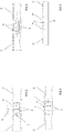
Figures 2-9 illustrate respective steps of a method according to the invention. - With reference to the accompanying drawings, the
numeral 1 denotes a machine for making smoking articles having a cavity according to this invention. - It should be noted that the expression "smoking articles" is used to mean articles of various kinds such as, for example, traditional. filter cigarettes or articles of the "heat not burn" type (HNB, where the article is only heated and not burnt), or rods, that is to say, sub-units of these articles.
Figures 2-9 show filter cigarettes during the steps in their production. - With reference to
Figure 1 , themachine 1 according to the invention comprises: a pickingdrum 2 having at least one seat (preferably a plurality of seats) for conveying a full filter rod S (that is, a rod without a cavity) having a multiple length (for example, a quadruple length) along a path); and a first cutting assembly 3 (comprising at least one blade) for cutting the full filter rod S having a multiple length into two filter units F (preferably identical). Themachine 1 also comprises a combiningdrum 4 that: receives in a seat of it two rods T comprising tobacco axially aligned and spaced from each other, and receives, in the same seat, the two filter units F interposed between the two rods T comprising tobacco. - The
machine 1 also comprises separation means 5 (seeFigures 2-4 ) downstream of the first cutting assembly 3 (preferably associated with the combiningdrum 4, as in the case illustrated) for separating the filter units F from each other in such a way that each one contacts a rod T comprising tobacco (at the respective ends thereof) and in such a way that an empty space V is formed between the two filter units F. The empty space V between the two filter units F (distance) is equal to the longitudinal dimensions of the two cavities C to be obtained (one for each smoking article A, preferably identical to each other). - The
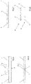
machine 1 also comprises awrapping unit 6 for completely wrapping with a wrap I the two filter units F and the empty space V between the filter units F and partially wrapping the two rods T comprising tobacco for connecting them to the filter units F (this being the operation known as "rolling", seeFigures 6 and 7 ). - The
machine 1 also comprises a second cutting assembly 7 for transversally cutting the wrapped wrap I at said empty space V in such a way as to define a cavity C for each filter unit F wrapped by the wrap I and adjacent to the filter unit F. Refer toFigure 8 , where a cutting line 70 is represented as a solid line. The cavity C, on the other hand, is shown inFigures 7-9 . - Advantageously, the
machine 1 according to the invention allows smoking articles A having a cavity C to be made without using a dedicated machine 1 (combiner) to form the filter plugs provided with cavities. Themachine 1 according to the invention is therefore economical and structurally simple compared to prior art solutions. - In the embodiment illustrated, as mentioned, the separation means 5 are associated with the combining drum 4 (that is to say, they operate in proximity thereto or are part of it); alternatively, the separation means 5 might be associated with a different drum that is also downstream of the
first cutting assembly 3 and upstream of the unit for feeding the wrap I. - Preferably, the separation means 5 comprise pneumatic means (air taken in or blown out).
- For example, the separation means 5 comprise at least two suction supports 50, arranged at the seat and configured for axially moving each filter unit F in such a way that the empty space V is arranged between the two filter units F (see
Figures 2-4 ). - In a variant not illustrated, the separation means 5 comprise at least two motorized rollers, arranged externally to the combining
drum 4, each being able to axially move a filter unit F in such a way that the empty space V is arranged between the two filter units F. - The
machine 1 according to the embodiment ofFigure 1 is described below in its entirety. - A mass of full filter rods S of multiple (for example, quadruple) length is contained in a
hopper 20 which has a bottom outlet opening coupled to the picking drum 2 (which has peripheral suction seats for the filter rods S of multiple length). - The picking
drum 2 acts in conjunction with cutting means 21 (in this case comprising two rotary blades) for cutting the full filter rods S of multiple length transversally so as to obtain double-length filter rods S, as described above. - The double-length filter rods S are transferred from the picking
drum 2 to atransit drum 30 which is provided with peripheral suction seats. - From the
transit drum 30, the double-length filter rods S are transferred to afirst cutting drum 31 which is provided with peripheral suction seats and which acts in conjunction with the first cutting assembly 3 (comprising a rotary blade) which cuts each filter rod S into two filter units F (preferably identical). - From the
cutting drum 31, the separate but axially adjacent filter units F are then transferred to a first infeedstation 41 of the combiningdrum 4 provided with peripheral suction seats. At a second infeedstation 42 of the combiningdrum 4, arranged downstream of the first infeedstation 41 along a feed path, two rods T comprising tobacco are fed into each seat (by a feed drum 43) in such a way that the rods are axially aligned, axially spaced and external to the filter units F. The filter units F and the rods T containing tobacco are all axially aligned (since they are housed in the same seat). - Operating at the combining
drum 4 there are separation means 5 which separate the filter units F from each other by spacing them axially in such a way that each of them (with a respective end of it) contacts a rod T comprising tobacco and in such a way that an empty space V is formed between the two filter units F. Thus, each seat contains a group G formed of two rods T comprising tobacco, two filter units F and an empty space V between the filter units F. - The groups G thus formed are transferred to a
coupling drum 60 provided with peripheral suction seats for the groups. Operating at thecoupling drum 60 there is a feed unit for feeding a wrap I (a connecting strip which is gummed, that is, provided with adhesive) for each group G and for applying it as described above (so as to wrap completely the two filter units F and the empty space V between the filter units F and partially the two rods T comprising tobacco in order to connect them to the filter units F). - From the
coupling drum 60, the groups G provided with the wraps I are transferred to arolling drum 61 where wrapping around the groups G is completed by thewrapping unit 6. - Lastly, the
machine 1 comprises asecond cutting drum 71, where a second cutting assembly 7 cuts each group G (preferably centrally) where the empty space V between the two filter units F is, to form two juxtaposed smoking articles A (in the case illustrated, filter cigarettes) having a cavity C. - The end section of the
machine 1 comprises a tip-turningdrum 8, where what is known as "tip-turning" occurs, to pass from two juxtaposed rows of smoking articles A, oriented mirror symmetrically, to a single row of smoking articles A oriented in the same direction (where the spacing is obviously half of that of the two juxtaposed rows), as shown inFigure 9 . - This invention also relates to a method for producing smoking articles A having a cavity C, comprising the steps of:
- feeding a full filter rod S having a multiple length (
Figure 2 ), and - transversally cutting the full filter rod S having a multiple length into two units (preferably identical,
Figure 3 ); and - feeding two rods T comprising tobacco, axially aligned with each other and spaced in such a way that the two filter units F are arranged between them (axially aligned) (
Figure 2 ); and - spacing the two filter units F (that is moving them axially away from each other) in such a way that an empty space V is defined between them and each contacts a rod T comprising tobacco (
Figure 4, Figure5 ); and then: - feeding a wrap I (
Figure 6 ); - wrapping the wrap I for covering: completely the two filter units F and the empty space V between the two units, and partially the two rods T comprising tobacco to connect them to the filter units F (
Figure 7 ); - transversally cutting the wrap I at the empty space V between the two filter units F, in such a way as to define a cavity C for each filter unit F wrapped by the wrap I and adjacent to the filter unit F (
Figure 8 ). -
Figure 9 , in particular, shows smoking articles A (cigarettes) which, after being cut, have been "tip-turned" so that both are oriented in the same direction, as described above. - Preferably, the step of spacing the two filter units F comprises the sub-step of moving the two filter units F axially away from each other in such a way that an empty space V equal to the sum of the cavities C to be obtained is defined between them (that is, equal to the sum of the cavities C adjacent to each filter unit F).
- Preferably, the step of feeding a wrap I comprises the sub-step of feeding a wrap I with a gram weight of between 45 and 100 g/m2. Advantageously, this forms smoking articles A where the wrap I is located at the end that is intended to come into contact with the mouth of a user (smoker) and where the thickness of the wrap I is greater than that in prior art solutions (usually between 30 and 40 g/m2). That way, the wrap I is not damaged despite coming into contact with the user's mouth.
- This invention also relates to a smoking article A obtained with a method as described above (see
Figure 9 , where 2 are shown). More specifically, the article comprises: a rod T comprising tobacco T; a filter unit F, axially in contact with the rod T comprising tobacco, and a wrap I that wraps partially the rod T comprising tobacco and completely the filter unit F, in such a way as to protrude from the filter unit F to define a cavity C. - Preferably, the wrap I has a gram weight of between 45 and 100 g/m2. The invention also relates to a method for modifying an existing machine 1 (what is known as a filter tip attachment) for making smoking articles A having a cavity C, where the existing machine comprises:
- a picking
drum 2 having at least one seat for conveying a full filter rod S of multiple length; - a combining
drum 4 that: receives in a seat of it two rods T comprising tobacco axially aligned and spaced from each other; and receives in its seat the filter rod S having a multiple length between the two rods T comprising tobacco; - a
wrapping unit 6 for completely wrapping with a wrap I the filter rod S having a multiple length and partially wrapping the two rods T comprising tobacco (for connecting them to the rod S); - cutting means for cutting the wrap I at the wrapped filter rod S to define two distinct smoking articles A;
- end separation means for axially separating the two smoking articles A from each other.
- The modifying method according to the invention comprises the following steps:
- arranging a
first cutting assembly 3 upstream of the combiningdrum 4 for cutting the filter rod S into two filter units F; - providing separation means 5 downstream of the
first cutting assembly 3 for separating the filter units F in such a way that each contacts a rod T comprising tobacco and an empty space V is defined between the two filter units F; - deactivating/removing the end separation means.
- The method described above allows modifying an existing machine 1 (what is known as a filter tip attachment) with a few simple and inexpensive modifications to make it suitable for making smoking articles A having a cavity C.
- Obviously, the invention also comprises the reverse method to return the
machine 1 to the initial conditions, comprising the following steps: - removing the
first cutting assembly 3; - removing/deactivating the first separation means 5;
- reactivating/arranging the end separation means.
- The invention further relates to a
kit - a picking
drum 2 having at least one seat for conveying a full filter rod S of multiple length; - a combining
drum 4 that: receives in a seat of it two rods T comprising tobacco axially aligned and spaced from each other; and receives in its seat the filter rod S having a multiple length between the two rods T comprising tobacco; - a
wrapping unit 6 for completely wrapping with a wrap I the filter rod S having a multiple length and partially wrapping the two rods T comprising tobacco for connecting them to the filter units F; - cutting means for cutting the wrap I at the wrapped filter rod S to define two distinct smoking articles A;
- end separation means for axially separating the two smoking articles A from each other.
- The
kit - a
first cutting assembly 3 disposable upstream of the combiningdrum 4; - separation means 5 disposable downstream of the
first cutting assembly 3. - The
kit
Claims (10)
- A machine (1) for producing smoking articles (A) having a cavity (C), comprising:- a picking drum (2) having at least one seat for conveying a full filter rod (S) having a multiple length;- a first cutting assembly (3) for cutting the full filter rod (S) having a multiple length into two filter units (F);- a combining drum (4) that: receives in a seat of it two rods (T) comprising tobacco (T) axially aligned and spaced from each other; receives in its seat the two filter units (F) between the two rods (T) comprising tobacco;- separation means (5), arranged downstream of the first cutting group (3), for separating the filter units (F) from each other in such a way that each one contacts a rod (T) comprising tobacco and in such a way that an empty space (V) is formed between the two filter units (F);- a wrapping unit (6) for completely wrapping with a wrap (I) the two filter units (F) and the empty space (V) between the filter units (F) and partially wrapping the two rods (T) comprising tobacco for connecting them to the filter units (F);- a second cutting assembly (7) for transversally cutting the wrapped wrap (I) at said empty space (V) in such a way as to define a cavity (C) for each filter unit (F) wrapped by the wrap (I) and adjacent to the filter unit (F).
- The machine (1) of the preceding claim wherein the separation means (5) comprise pneumatic means.
- The machine (1) of claim 1 or 2, wherein the separation means (5) comprise at least two suction supports (50), arranged at the seat and configured for axially moving each filter unit (F) in such a way that the empty space (V) is arranged between the two filter units (F).
- The machine (1) of claim 1 or 2, wherein the separation means (5) comprise at least two motorized rollers, arranged externally to the combining drum (4), each being able to axially move a filter unit (F) in such a way that the empty space (V) is arranged between the two filter units (F).
- A method for producing smoking articles (A) having a cavity (C), comprising the steps of:- feeding a full filter rod (S) having a multiple length; transversally cutting the full filter rod (S) having a multiple length into two filter units (F); and- feeding two rods (T) comprising tobacco, axially aligned with each other and spaced in such a way that the two filter units (F) are arranged between them; and- spacing the two filter units (F) in such a way that an empty space (V) is defined between them and that each contacts a rod (T) comprising tobacco; and then:- feeding a wrap (I);- wrapping the wrap (I) for covering: completely the two filter units (F) and the empty space (V) between the filter units (F), and partially the two rods (T) comprising tobacco for connecting them to the filter units (F);- transversally cutting the wrap (I) at the empty space (V) between the two filter units (F), in such a way as to define a cavity (C) for each filter unit (F) wrapped by the wrap (I) and adjacent to the filter unit (F).
- The method of the preceding claim, wherein the step of spacing the two filter units (F) comprises the sub-step of moving the two filter units (F) axially away from each other in such a way that an empty space (V) equal to the sum of the cavities (C) to be obtained is defined between them.
- The method of claim 5 or 6, wherein the step of feeding a wrap (I) comprises the sub-step of feeding a wrap (I) with a weight between 45 and 100 g/m2.
- A smoking article (A) produced with the method of any of the claims from 5 to 8, comprising a rod (T) comprising tobacco; a filter unit (F) axially contacting the rod (T) comprising tobacco; and a wrap (I) that wraps partially the rod (T) comprising tobacco and completely the filter unit (F), in such a way as to protrude from the filter unit (F) to define a cavity (C).
- A method for modifying an existing machine for producing smoking articles (A) having a cavity (C), wherein the existing machine comprises:- a picking drum (2) having at least one seat for conveying a full filter rod (S) having a multiple length;- a combining drum (4) that: receives in a seat of it two rods (T) comprising tobacco (T) axially aligned and spaced from each other; and receives in its seat the filter rod (S) having a multiple length between the two rods (T) comprising tobacco;- a wrapping unit (6) for completely wrapping with a wrap (I) the filter rod (S) having a multiple length and partially wrapping the two rods (T) comprising tobacco for connecting them to the filter units (F);- cutting means for cutting the wrap (I) at the wrapped filter rod (S) to define two distinct smoking articles (A);- end separation means for axially separating the two smoking articles (A);the method comprises the steps of:- arranging a first cutting assembly (3) upstream of the combining drum (4) for cutting the filter rod (S) into two filter units (F);- providing separation means (5) downstream of the first cutting assembly (3) for separating the filter units (F) in such a way that each contacts a rod (T) comprising tobacco and an empty space (V) is defined between the two filter units (F);- deactivating/removing the end separation means.
- A kit (3, 5) for modifying an existing machine for producing smoking articles (A) having a cavity (C), wherein the existing machine comprises:- a picking drum (2) having at least one seat for conveying a full filter rod (S) having a multiple length;- a combining drum (4) that: receives in a seat of it two rods (T) comprising tobacco (T) axially aligned and spaced from each other; and receives in its seat the filter rod (S) having a multiple length between the two rods (T) comprising tobacco;- a wrapping unit (6) for completely wrapping with a wrap (I) the filter rod (S) having a multiple length and partially wrapping the two rods (T) comprising tobacco for connecting them to the filter units (F);- cutting means for cutting the wrap (I) at the wrapped filter rod (S) to define two distinct smoking articles (A);- end separation means (5) for axially separating the two smoking articles (A);the kit (3, 5) comprises:- a first cutting assembly (3) disposable upstream of the combining drum (4);- separation means (5) disposable downstream of the first cutting assembly (3).
Applications Claiming Priority (1)
| Application Number | Priority Date | Filing Date | Title |
|---|---|---|---|
| IT102021000016409A IT202100016409A1 (en) | 2021-06-23 | 2021-06-23 | Machine and method for the production of smoking articles provided with cavities |
Publications (2)
| Publication Number | Publication Date |
|---|---|
| EP4108107A1 true EP4108107A1 (en) | 2022-12-28 |
| EP4108107B1 EP4108107B1 (en) | 2025-08-13 |
Family
ID=77801994
Family Applications (1)
| Application Number | Title | Priority Date | Filing Date |
|---|---|---|---|
| EP22180457.8A Active EP4108107B1 (en) | 2021-06-23 | 2022-06-22 | Machine and method for producing smoking articles having a cavity |
Country Status (3)
| Country | Link |
|---|---|
| EP (1) | EP4108107B1 (en) |
| IT (1) | IT202100016409A1 (en) |
| PL (1) | PL4108107T3 (en) |
Citations (5)
| Publication number | Priority date | Publication date | Assignee | Title |
|---|---|---|---|---|
| GB776777A (en) * | 1953-02-05 | 1957-06-12 | Molins Machine Co Ltd | Improvements in or relating to mouthpiece cigarettes and to their manufacture |
| GB862676A (en) * | 1957-09-21 | 1961-03-15 | Kurt Koerber | Method and apparatus for producing filter mouthpieces for cigarettes or the like |
| WO2002003819A1 (en) * | 2000-07-12 | 2002-01-17 | Philip Morris Products S.A. | Recess filter and smokeable article containing a recess filter |
| EP1994838A1 (en) * | 2007-05-23 | 2008-11-26 | Hauni Maschinenbau Aktiengesellschaft | Conveying drum |
| EP2946677A1 (en) * | 2013-03-06 | 2015-11-25 | Japan Tobacco Inc. | Cigarette production method, cigarette, and double cigarette |
-
2021
- 2021-06-23 IT IT102021000016409A patent/IT202100016409A1/en unknown
-
2022
- 2022-06-22 PL PL22180457.8T patent/PL4108107T3/en unknown
- 2022-06-22 EP EP22180457.8A patent/EP4108107B1/en active Active
Patent Citations (5)
| Publication number | Priority date | Publication date | Assignee | Title |
|---|---|---|---|---|
| GB776777A (en) * | 1953-02-05 | 1957-06-12 | Molins Machine Co Ltd | Improvements in or relating to mouthpiece cigarettes and to their manufacture |
| GB862676A (en) * | 1957-09-21 | 1961-03-15 | Kurt Koerber | Method and apparatus for producing filter mouthpieces for cigarettes or the like |
| WO2002003819A1 (en) * | 2000-07-12 | 2002-01-17 | Philip Morris Products S.A. | Recess filter and smokeable article containing a recess filter |
| EP1994838A1 (en) * | 2007-05-23 | 2008-11-26 | Hauni Maschinenbau Aktiengesellschaft | Conveying drum |
| EP2946677A1 (en) * | 2013-03-06 | 2015-11-25 | Japan Tobacco Inc. | Cigarette production method, cigarette, and double cigarette |
Also Published As
| Publication number | Publication date |
|---|---|
| EP4108107B1 (en) | 2025-08-13 |
| PL4108107T3 (en) | 2025-11-03 |
| IT202100016409A1 (en) | 2022-12-23 |
Similar Documents
| Publication | Publication Date | Title |
|---|---|---|
| JP7285294B2 (en) | Improved assembly of smoking articles | |
| CA2893100C (en) | Improvements relating to smoking article assembly | |
| AU2012264647A1 (en) | Modular apparatus for smoking article manufacture | |
| CN111480878B (en) | Manufacture of rod-shaped smoking articles | |
| KR20160140788A (en) | A smoking article assembly machine for assembling smoking articles having segmented filters | |
| US20040200486A1 (en) | Method for combining smoking article components | |
| EP4108107B1 (en) | Machine and method for producing smoking articles having a cavity | |
| US20060207614A1 (en) | Method for producing filter cigarettes | |
| GB776777A (en) | Improvements in or relating to mouthpiece cigarettes and to their manufacture | |
| EP4329524A1 (en) | Manufacturing method and manufacturing machine for the production of heat-not-burn smoking articles | |
| US4283187A (en) | Apparatus for forming composite rods | |
| US20040221856A1 (en) | Filter tipping machine with double tipping paper feed | |
| GB1573801A (en) | Method and apparatus for forming composite mouthpiece rod | |
| HK1216490B (en) | Modular apparatus for smoking article assembly and method of reconfiguring the same | |
| HK1224526B (en) | Modular apparatus for smoking article manufacture | |
| HK1224526A1 (en) | Modular apparatus for smoking article manufacture | |
| HK1198799B (en) | Modular apparatus for smoking article manufacture |
Legal Events
| Date | Code | Title | Description |
|---|---|---|---|
| PUAI | Public reference made under article 153(3) epc to a published international application that has entered the european phase |
Free format text: ORIGINAL CODE: 0009012 |
|
| STAA | Information on the status of an ep patent application or granted ep patent |
Free format text: STATUS: THE APPLICATION HAS BEEN PUBLISHED |
|
| AK | Designated contracting states |
Kind code of ref document: A1 Designated state(s): AL AT BE BG CH CY CZ DE DK EE ES FI FR GB GR HR HU IE IS IT LI LT LU LV MC MK MT NL NO PL PT RO RS SE SI SK SM TR |
|
| STAA | Information on the status of an ep patent application or granted ep patent |
Free format text: STATUS: REQUEST FOR EXAMINATION WAS MADE |
|
| P01 | Opt-out of the competence of the unified patent court (upc) registered |
Effective date: 20230528 |
|
| 17P | Request for examination filed |
Effective date: 20230621 |
|
| RBV | Designated contracting states (corrected) |
Designated state(s): AL AT BE BG CH CY CZ DE DK EE ES FI FR GB GR HR HU IE IS IT LI LT LU LV MC MK MT NL NO PL PT RO RS SE SI SK SM TR |
|
| GRAP | Despatch of communication of intention to grant a patent |
Free format text: ORIGINAL CODE: EPIDOSNIGR1 |
|
| STAA | Information on the status of an ep patent application or granted ep patent |
Free format text: STATUS: GRANT OF PATENT IS INTENDED |
|
| INTG | Intention to grant announced |
Effective date: 20250314 |
|
| GRAS | Grant fee paid |
Free format text: ORIGINAL CODE: EPIDOSNIGR3 |
|
| GRAA | (expected) grant |
Free format text: ORIGINAL CODE: 0009210 |
|
| STAA | Information on the status of an ep patent application or granted ep patent |
Free format text: STATUS: THE PATENT HAS BEEN GRANTED |
|
| AK | Designated contracting states |
Kind code of ref document: B1 Designated state(s): AL AT BE BG CH CY CZ DE DK EE ES FI FR GB GR HR HU IE IS IT LI LT LU LV MC MK MT NL NO PL PT RO RS SE SI SK SM TR |
|
| REG | Reference to a national code |
Ref country code: GB Ref legal event code: FG4D |
|
| REG | Reference to a national code |
Ref country code: CH Ref legal event code: EP |
|
| REG | Reference to a national code |
Ref country code: DE Ref legal event code: R096 Ref document number: 602022019269 Country of ref document: DE |
|
| REG | Reference to a national code |
Ref country code: IE Ref legal event code: FG4D |
|
| REG | Reference to a national code |
Ref country code: NL Ref legal event code: FP |
|
| PG25 | Lapsed in a contracting state [announced via postgrant information from national office to epo] |
Ref country code: IS Free format text: LAPSE BECAUSE OF FAILURE TO SUBMIT A TRANSLATION OF THE DESCRIPTION OR TO PAY THE FEE WITHIN THE PRESCRIBED TIME-LIMIT Effective date: 20251213 |
|
| PG25 | Lapsed in a contracting state [announced via postgrant information from national office to epo] |
Ref country code: NO Free format text: LAPSE BECAUSE OF FAILURE TO SUBMIT A TRANSLATION OF THE DESCRIPTION OR TO PAY THE FEE WITHIN THE PRESCRIBED TIME-LIMIT Effective date: 20251113 |
|
| REG | Reference to a national code |
Ref country code: LT Ref legal event code: MG9D |
|
| PG25 | Lapsed in a contracting state [announced via postgrant information from national office to epo] |
Ref country code: PT Free format text: LAPSE BECAUSE OF FAILURE TO SUBMIT A TRANSLATION OF THE DESCRIPTION OR TO PAY THE FEE WITHIN THE PRESCRIBED TIME-LIMIT Effective date: 20251215 |
|
| PG25 | Lapsed in a contracting state [announced via postgrant information from national office to epo] |
Ref country code: FI Free format text: LAPSE BECAUSE OF FAILURE TO SUBMIT A TRANSLATION OF THE DESCRIPTION OR TO PAY THE FEE WITHIN THE PRESCRIBED TIME-LIMIT Effective date: 20250813 |
|
| PG25 | Lapsed in a contracting state [announced via postgrant information from national office to epo] |
Ref country code: HR Free format text: LAPSE BECAUSE OF FAILURE TO SUBMIT A TRANSLATION OF THE DESCRIPTION OR TO PAY THE FEE WITHIN THE PRESCRIBED TIME-LIMIT Effective date: 20250813 |
|
| PG25 | Lapsed in a contracting state [announced via postgrant information from national office to epo] |
Ref country code: GR Free format text: LAPSE BECAUSE OF FAILURE TO SUBMIT A TRANSLATION OF THE DESCRIPTION OR TO PAY THE FEE WITHIN THE PRESCRIBED TIME-LIMIT Effective date: 20251114 |
|
| PG25 | Lapsed in a contracting state [announced via postgrant information from national office to epo] |
Ref country code: SE Free format text: LAPSE BECAUSE OF FAILURE TO SUBMIT A TRANSLATION OF THE DESCRIPTION OR TO PAY THE FEE WITHIN THE PRESCRIBED TIME-LIMIT Effective date: 20250813 |
|
| PG25 | Lapsed in a contracting state [announced via postgrant information from national office to epo] |
Ref country code: LV Free format text: LAPSE BECAUSE OF FAILURE TO SUBMIT A TRANSLATION OF THE DESCRIPTION OR TO PAY THE FEE WITHIN THE PRESCRIBED TIME-LIMIT Effective date: 20250813 |
|
| PG25 | Lapsed in a contracting state [announced via postgrant information from national office to epo] |
Ref country code: BG Free format text: LAPSE BECAUSE OF FAILURE TO SUBMIT A TRANSLATION OF THE DESCRIPTION OR TO PAY THE FEE WITHIN THE PRESCRIBED TIME-LIMIT Effective date: 20250813 |
|
| PG25 | Lapsed in a contracting state [announced via postgrant information from national office to epo] |
Ref country code: RS Free format text: LAPSE BECAUSE OF FAILURE TO SUBMIT A TRANSLATION OF THE DESCRIPTION OR TO PAY THE FEE WITHIN THE PRESCRIBED TIME-LIMIT Effective date: 20251113 |
|
| PG25 | Lapsed in a contracting state [announced via postgrant information from national office to epo] |
Ref country code: ES Free format text: LAPSE BECAUSE OF FAILURE TO SUBMIT A TRANSLATION OF THE DESCRIPTION OR TO PAY THE FEE WITHIN THE PRESCRIBED TIME-LIMIT Effective date: 20250813 |
|
| REG | Reference to a national code |
Ref country code: AT Ref legal event code: MK05 Ref document number: 1823695 Country of ref document: AT Kind code of ref document: T Effective date: 20250813 |
|
| PG25 | Lapsed in a contracting state [announced via postgrant information from national office to epo] |
Ref country code: SM Free format text: LAPSE BECAUSE OF FAILURE TO SUBMIT A TRANSLATION OF THE DESCRIPTION OR TO PAY THE FEE WITHIN THE PRESCRIBED TIME-LIMIT Effective date: 20250813 |
|
| PG25 | Lapsed in a contracting state [announced via postgrant information from national office to epo] |
Ref country code: DK Free format text: LAPSE BECAUSE OF FAILURE TO SUBMIT A TRANSLATION OF THE DESCRIPTION OR TO PAY THE FEE WITHIN THE PRESCRIBED TIME-LIMIT Effective date: 20250813 |
|
| PG25 | Lapsed in a contracting state [announced via postgrant information from national office to epo] |
Ref country code: AT Free format text: LAPSE BECAUSE OF FAILURE TO SUBMIT A TRANSLATION OF THE DESCRIPTION OR TO PAY THE FEE WITHIN THE PRESCRIBED TIME-LIMIT Effective date: 20250813 |
|
| PG25 | Lapsed in a contracting state [announced via postgrant information from national office to epo] |
Ref country code: IT Free format text: LAPSE BECAUSE OF FAILURE TO SUBMIT A TRANSLATION OF THE DESCRIPTION OR TO PAY THE FEE WITHIN THE PRESCRIBED TIME-LIMIT Effective date: 20250813 |
|
| PG25 | Lapsed in a contracting state [announced via postgrant information from national office to epo] |
Ref country code: CZ Free format text: LAPSE BECAUSE OF FAILURE TO SUBMIT A TRANSLATION OF THE DESCRIPTION OR TO PAY THE FEE WITHIN THE PRESCRIBED TIME-LIMIT Effective date: 20250813 |
|
| PG25 | Lapsed in a contracting state [announced via postgrant information from national office to epo] |
Ref country code: SK Free format text: LAPSE BECAUSE OF FAILURE TO SUBMIT A TRANSLATION OF THE DESCRIPTION OR TO PAY THE FEE WITHIN THE PRESCRIBED TIME-LIMIT Effective date: 20250813 Ref country code: EE Free format text: LAPSE BECAUSE OF FAILURE TO SUBMIT A TRANSLATION OF THE DESCRIPTION OR TO PAY THE FEE WITHIN THE PRESCRIBED TIME-LIMIT Effective date: 20250813 |
|
| REG | Reference to a national code |
Ref country code: DE Ref legal event code: R097 Ref document number: 602022019269 Country of ref document: DE |
|
| PLBE | No opposition filed within time limit |
Free format text: ORIGINAL CODE: 0009261 |
|
| STAA | Information on the status of an ep patent application or granted ep patent |
Free format text: STATUS: NO OPPOSITION FILED WITHIN TIME LIMIT |
|
| REG | Reference to a national code |
Ref country code: CH Ref legal event code: L10 Free format text: ST27 STATUS EVENT CODE: U-0-0-L10-L00 (AS PROVIDED BY THE NATIONAL OFFICE) Effective date: 20260624 |
|
| PG25 | Lapsed in a contracting state [announced via postgrant information from national office to epo] |
Ref country code: LT Free format text: LAPSE BECAUSE OF FAILURE TO SUBMIT A TRANSLATION OF THE DESCRIPTION OR TO PAY THE FEE WITHIN THE PRESCRIBED TIME-LIMIT Effective date: 20250813 |
|
| 26N | No opposition filed |
Effective date: 20260515 |