EP4107371B1 - Dispositif de distribution d'huile d'un palier a roulement de turbomachine d'aeronef - Google Patents
Dispositif de distribution d'huile d'un palier a roulement de turbomachine d'aeronef Download PDFInfo
- Publication number
- EP4107371B1 EP4107371B1 EP21707356.8A EP21707356A EP4107371B1 EP 4107371 B1 EP4107371 B1 EP 4107371B1 EP 21707356 A EP21707356 A EP 21707356A EP 4107371 B1 EP4107371 B1 EP 4107371B1
- Authority
- EP
- European Patent Office
- Prior art keywords
- scoop
- oil
- bearing
- annular
- circuit
- Prior art date
- Legal status (The legal status is an assumption and is not a legal conclusion. Google has not performed a legal analysis and makes no representation as to the accuracy of the status listed.)
- Active
Links
Images


Classifications
-
- F—MECHANICAL ENGINEERING; LIGHTING; HEATING; WEAPONS; BLASTING
- F01—MACHINES OR ENGINES IN GENERAL; ENGINE PLANTS IN GENERAL; STEAM ENGINES
- F01D—NON-POSITIVE DISPLACEMENT MACHINES OR ENGINES, e.g. STEAM TURBINES
- F01D25/00—Component parts, details, or accessories, not provided for in, or of interest apart from, other groups
- F01D25/16—Arrangement of bearings; Supporting or mounting bearings in casings
- F01D25/162—Bearing supports
-
- F—MECHANICAL ENGINEERING; LIGHTING; HEATING; WEAPONS; BLASTING
- F01—MACHINES OR ENGINES IN GENERAL; ENGINE PLANTS IN GENERAL; STEAM ENGINES
- F01D—NON-POSITIVE DISPLACEMENT MACHINES OR ENGINES, e.g. STEAM TURBINES
- F01D25/00—Component parts, details, or accessories, not provided for in, or of interest apart from, other groups
- F01D25/18—Lubricating arrangements
- F01D25/183—Sealing means
-
- F—MECHANICAL ENGINEERING; LIGHTING; HEATING; WEAPONS; BLASTING
- F02—COMBUSTION ENGINES; HOT-GAS OR COMBUSTION-PRODUCT ENGINE PLANTS
- F02C—GAS-TURBINE PLANTS; AIR INTAKES FOR JET-PROPULSION PLANTS; CONTROLLING FUEL SUPPLY IN AIR-BREATHING JET-PROPULSION PLANTS
- F02C7/00—Features, components parts, details or accessories, not provided for in, or of interest apart form groups F02C1/00 - F02C6/00; Air intakes for jet-propulsion plants
- F02C7/06—Arrangements of bearings; Lubricating
-
- F—MECHANICAL ENGINEERING; LIGHTING; HEATING; WEAPONS; BLASTING
- F16—ENGINEERING ELEMENTS AND UNITS; GENERAL MEASURES FOR PRODUCING AND MAINTAINING EFFECTIVE FUNCTIONING OF MACHINES OR INSTALLATIONS; THERMAL INSULATION IN GENERAL
- F16C—SHAFTS; FLEXIBLE SHAFTS; ELEMENTS OR CRANKSHAFT MECHANISMS; ROTARY BODIES OTHER THAN GEARING ELEMENTS; BEARINGS
- F16C33/00—Parts of bearings; Special methods for making bearings or parts thereof
- F16C33/30—Parts of ball or roller bearings
- F16C33/66—Special parts or details in view of lubrication
- F16C33/6637—Special parts or details in view of lubrication with liquid lubricant
- F16C33/6659—Details of supply of the liquid to the bearing, e.g. passages or nozzles
- F16C33/6677—Details of supply of the liquid to the bearing, e.g. passages or nozzles from radial inside, e.g. via a passage through the shaft and/or inner ring
-
- F—MECHANICAL ENGINEERING; LIGHTING; HEATING; WEAPONS; BLASTING
- F16—ENGINEERING ELEMENTS AND UNITS; GENERAL MEASURES FOR PRODUCING AND MAINTAINING EFFECTIVE FUNCTIONING OF MACHINES OR INSTALLATIONS; THERMAL INSULATION IN GENERAL
- F16C—SHAFTS; FLEXIBLE SHAFTS; ELEMENTS OR CRANKSHAFT MECHANISMS; ROTARY BODIES OTHER THAN GEARING ELEMENTS; BEARINGS
- F16C33/00—Parts of bearings; Special methods for making bearings or parts thereof
- F16C33/30—Parts of ball or roller bearings
- F16C33/66—Special parts or details in view of lubrication
- F16C33/6637—Special parts or details in view of lubrication with liquid lubricant
- F16C33/6685—Details of collecting or draining, e.g. returning the liquid to a sump
-
- F—MECHANICAL ENGINEERING; LIGHTING; HEATING; WEAPONS; BLASTING
- F05—INDEXING SCHEMES RELATING TO ENGINES OR PUMPS IN VARIOUS SUBCLASSES OF CLASSES F01-F04
- F05D—INDEXING SCHEME FOR ASPECTS RELATING TO NON-POSITIVE-DISPLACEMENT MACHINES OR ENGINES, GAS-TURBINES OR JET-PROPULSION PLANTS
- F05D2260/00—Function
- F05D2260/98—Lubrication
-
- F—MECHANICAL ENGINEERING; LIGHTING; HEATING; WEAPONS; BLASTING
- F16—ENGINEERING ELEMENTS AND UNITS; GENERAL MEASURES FOR PRODUCING AND MAINTAINING EFFECTIVE FUNCTIONING OF MACHINES OR INSTALLATIONS; THERMAL INSULATION IN GENERAL
- F16C—SHAFTS; FLEXIBLE SHAFTS; ELEMENTS OR CRANKSHAFT MECHANISMS; ROTARY BODIES OTHER THAN GEARING ELEMENTS; BEARINGS
- F16C2360/00—Engines or pumps
- F16C2360/23—Gas turbine engines
- F16C2360/24—Turbochargers
-
- Y—GENERAL TAGGING OF NEW TECHNOLOGICAL DEVELOPMENTS; GENERAL TAGGING OF CROSS-SECTIONAL TECHNOLOGIES SPANNING OVER SEVERAL SECTIONS OF THE IPC; TECHNICAL SUBJECTS COVERED BY FORMER USPC CROSS-REFERENCE ART COLLECTIONS [XRACs] AND DIGESTS
- Y02—TECHNOLOGIES OR APPLICATIONS FOR MITIGATION OR ADAPTATION AGAINST CLIMATE CHANGE
- Y02T—CLIMATE CHANGE MITIGATION TECHNOLOGIES RELATED TO TRANSPORTATION
- Y02T50/00—Aeronautics or air transport
- Y02T50/60—Efficient propulsion technologies, e.g. for aircraft
Definitions
- the present invention relates to an oil distribution device for a rolling bearing for an aircraft turbomachine.
- the state of the art includes in particular the documents FR-A1-3 035 154 , FR-A1-3 066 549 , WO-A1-2015/075355 , US-B2-10 082 037 And EP-A1-3 112 636 .
- a turbomachine comprises a certain number of rolling bearings which are intended to support the rotation of the rotor of the turbomachine, in particular relative to a fixed support such as the casing thereof.
- oil is typically injected onto the bearings of these bearings to lubricate and cool them.
- oil is necessary to confine the rolling bearings within oil chambers and to ensure that these oil chambers are sealed from air chambers adjacent to the engine, which must be free of oil.
- some oil chambers are delimited between the shaft supported in rotation by the rolling bearing and an annular cover secured to a fixed support linked to the turbomachine casing and arranged around the shaft.
- a dynamic annular seal is generally positioned between the shaft and the cover to ensure a seal between the oil chamber and an air chamber adjacent to the latter.
- the dynamic seal is mounted inside a flange itself fixed to the cover.
- Dynamic seals typically used in turbomachine rolling bearing oil chambers are segmented radial seals (SRS), comprising a plurality of ring segments distributed circumferentially around a seal raceway rotating with the rotor shaft. These segments are in sliding contact with the seal raceway. The friction between the seal segments and the seal raceway generates heat that must be removed in order to maintain the mechanical integrity of these elements.
- SRS segmented radial seals
- one technique consists of circulating cooling oil along the inner wall of the seal raceway.
- the dynamic seal may be located right next to a rolling bearing that is lubricated by oil in operation. It is known to lubricate a rolling bearing by means of an oil distribution ring.
- the rolling bearing is mounted on the oil distribution ring which includes an oil recovery scoop projected by a nozzle, in order to collect this oil and supply a lubrication circuit of the bearing.
- the present invention proposes an improvement to this technology which makes it possible in particular to optimize the cooling of the track of a dynamic seal, for example of the JRS type, arranged next to a lubricated rolling bearing.
- the reduction in the diameter of the raceway results in a reduction in the leakage section to be sealed by the dynamic seal, which further improves the efficiency of the sealing device.
- the disadvantage of using a single scoop to supply the circuit and both the lubrication of the bearing and the cooling of the seal raceway, is a risk of under-supplying the seal raceway and therefore poor cooling of the latter.
- the two scoops allow the two parts of the circuit to be supplied separately, and therefore generate a first flow of oil for cooling the seal track and a second flow of oil for lubricating the bearing.
- the role of the two scoops is therefore to properly supply the parts of the circuit while increasing the space requirement of the room as little as possible.
- the seal track is cooled by a dedicated oil flow which guarantees this cooling.
- FIG. 1 schematically and partially represents an oil chamber 2 of an aircraft turbomachine bearing.
- An oil distribution ring 5 is arranged around the shaft 4 coaxially with it, and is rotationally integral with it.
- the oil chamber 2 contains a bearing 8 comprising a plurality of rolling elements 10 engaged between an inner ring 12 mounted on the distribution ring 5, preferably by shrink fitting, and an outer ring 14 secured to the bearing support 3 fixed to the casing 1 of the turbomachine.
- the bearing support 3 may have a certain flexibility.
- the rolling elements 10 are balls.
- the type of bearing or rolling elements is not limiting within the scope of the present invention.
- Oil is injected into the oil chamber 2 in order to lubricate and cool the rolling elements 10 of the bearing.
- oil circulates in a circuit lubricating oil 7 integrated in the distribution ring 5 to an external cylindrical surface 5a of the distribution ring 5 which serves for mounting the internal ring 12.
- the oil is supplied by an oil nozzle 9 which is here located upstream of the distribution ring 5 (the expressions “upstream” and “downstream” here refer to the general flow of gases in the turbomachine).
- the ring 5 has a generally annular shape around the axis X and comprises at its upstream end a scoop 11 for recovering the oil sprayed by the nozzle 9.
- This scoop is in the form of a cylindrical rim oriented upstream in the example shown.
- the scoop 11 extends around and at a distance from the shaft 4 and defines with the latter an annular space for receiving the oil from the nozzle 9.
- the oil circuit 7 comprises at least one inlet opening onto the upstream end of the distribution ring 5, in the aforementioned oil receiving space.
- this inlet is formed by an upstream end 7aa of at least one channel 7a which has an elongated shape along the axis X and which comprises a downstream end 7ab located at the downstream end of the distribution ring 5.
- Oil ducts 15 oriented substantially radially relative to the axis X extend from the channel 7a to the surface 5a of the ring 5 for the purpose of lubricating the bearing 8.
- the inner ring 12 of the bearing 8 also comprises an integrated oil circuit 12a for the circulation of the oil supplied by the circuit 7 of the ring 5, to lubricate the rolling elements and their cage.
- the inner ring 12 is axially supported upstream on an annular shoulder 5b of the ring 5.
- the distribution ring 5 comprises an external thread 5c for screwing a nut 16 which bears axially on the downstream end of the ring 12 in order to tighten it axially against the shoulder 5b.
- the oil enclosure 2 further comprises a sealing system intended to ensure sealing of this oil enclosure relative to a neighboring air enclosure 20 which must be free of oil.
- the sealing system comprises in particular a dynamic annular seal 22.
- this dynamic seal 22 is composed of carbon ring segments.
- the dynamic seal 22 is held in an annular flange 28 itself mounted inside the cover 6.
- the flange 28 has a part 28a of L-shaped section which receives the dynamic seal 22.
- the dynamic annular seal 22 is associated with a seal race 26, which is rotatable and carried by the shaft 4.
- the race 26 has a contact surface 26a, in sliding contact with the dynamic annular seal 22.
- the contact surface 26a and the race 26 are treated to improve the seal/race sliding and minimize the wear of the dynamic annular seal 22.
- the sealing system also includes a labyrinth seal 23 arranged downstream of the dynamic seal 22, between a journal 21 mounted on the shaft 4 and the cover 6.
- the journal 21 is rotationally secured to the shaft 4 by means of splines 21a.
- the journal 21 is located downstream of the distribution ring 5 and comprises an upstream end in axial support against the downstream end of the ring 5, this downstream end forming an axial stop.
- a nut 24 is screwed onto the shaft 4, downstream of the journal 21, in order to press the latter axially against the ring 5 which is itself held axially tight against the dog teeth of the shaft 4.
- the ring 5 is preferably shrunk onto the shaft 4 to ensure its centering.
- the distribution ring 5 and the track 26 of the dynamic seal 22 are formed in a single piece, for example by additive manufacturing.
- the ring 5 and the track 26 are thus formed by a single-piece body which integrates the circuit 7.
- the circuit 7 extends axially downstream to the track 26 for the purpose of conduction cooling of the surface 26a.
- the aforementioned channel 7a thus has its downstream end 7ab which is located as close as possible to the downstream end of the track 26 and the body, and which is surrounded by the surface 26a.
- the channel 7 is rectilinear and located on a circumference centered on the axis X having a diameter D1.
- the surface 26a is located on a circumference centered on this axis X of diameter D3.
- the circuit 7 comprises at least one other channel 7b which has a generally elongated and preferably rectilinear shape and which is located on a circumference centered on the axis X of diameter D2.
- D1 is less than D2 which is less than D3, which means that the channel 7b extends between the channel 7a and the surface 26a.
- the channel 7b has a downstream end 7ba connected to the downstream end 7ab of the channel 7a and an upstream end 7bb which opens onto the surface 5a, or into the thread 5c, or between the surface 5a and the thread 5c, as in the example shown.
- This end 7bb can be bent in an L shape and comprise a part oriented radially outwards and opening for example into an annular groove 7c provided on the ring 5, which opens radially outwards.
- connection of the ends 7ab and 7ba can be achieved by at least one conduit 7d bent at C for example.
- the nut 16 may comprise at least one integrated oil circulation channel 29, which is intended to receive oil coming from the groove 7c.
- This channel 29 is for example inclined from upstream to downstream radially outwards and comprises a radially internal end opening opposite the groove 7c, and a radially external end opening outwards for the purpose of spraying oil outwards.
- the integration of the cooling circuit into the seal track 26 makes it possible to reduce its diameter, which has a double advantage. First of all, this reduces the radial size in this area. Furthermore, the friction of the seal 22 on the track 26 is less significant due to the lower peripheral speeds. Finally, the passage section between the seal 22 and the track 26 is smaller and therefore the leaks are also lower.
- the body may also include up to ten or more 7b channels. These 7b channels may have a circular shape in section. Their section may also change along the X axis. They may each have a circular section on an upstream portion and a rectangular section on a downstream portion.
- Channels 7a, 7b here extend parallel to the X axis although this is not limiting.
- the Applicant has noted that supplying the circuit by a single scoop can lead to a problem of insufficient cooling of the track 26. Indeed, the rolling elements 10 of the bearing 8 create a pumping phenomenon when they pass over the outlets of the conduits 15 carrying the oil. The bearing 8 consumes between 80% and 90% of the oil flow provided by the circuit 7 compared to only 20% to 10% for the track 26. It is difficult to control these proportions precisely and there is therefore a risk of undersupply of oil to the track 26.
- the proposed solution consists of using two separate scoops which are each dedicated to supplying a part of the circuit.
- FIG. 3 to 5 illustrate a first embodiment of a device according to the invention.
- This device includes all the features of the device described in the foregoing unless they are in contradiction with what follows and the drawings.
- the body 5 of the device further comprises a second annular scoop 11b for recovering oil which supplies a second part of said circuit for the purpose of lubricating the bearing.
- the first scoop 11a has a diameter smaller than that of the second scoop 11b.
- the scoops 11a, 11b have a general L-shape in axial section and each comprise a cylindrical part 11a1, 11b1, one axial end of which is connected to an annular rim 11a2, 11b2.
- the cylindrical parts 11a1, 11b1 extend around each other and the annular rims 11a2, 11b2 are axially offset relative to each other.
- the rim 11b2 is here located upstream of the rim 11a2.
- the flanges 11a2, 11b2 have predetermined radial dimensions so as to guarantee the retention of the oil sprayed by the nozzle 9 during operation and thus prevent any overflow of this oil (cf. figure 4 ).
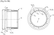
- the first part 7x of the circuit 7 comprises at least a first channel 7a extending in the body 5 between the first scoop 11a and the track 26.
- the Figures 5A and 5B allow to see that this channel has an annular shape.
- Longitudinal ribs 7x1 are located in the channel 7a and extend over all or part of its length to facilitate the routing of the oil while limiting the pressure losses. Furthermore, due to the relatively large length of the channel 7, the ribs 7x1 provide the connection between the radially internal and external annular portions of the body 5 separated by this channel 7.
- the downstream end of the channel 7a can be connected to other elements (7b, 7c, 7d) similar to those of the figures 1 And 2 .
- FIG 4 illustrates the path of the oil from the nozzle 9.
- This nozzle 9 advantageously comprises a first oil projection outlet 9a, oriented for example radially inwards, and configured to supply oil to the first scoop 11a. This oil then travels in the first channel 7a for the purpose of cooling the track 26, and until it emerges at the nut 16 similar to that of the figures 1 And 2 .
- the nozzle 9 comprises a second oil projection outlet 9b, oriented for example radially outwards, and configured to supply oil to the second scoop 11b. This oil then travels through the channels 7y1 in order to lubricate the bearing 8.
- the scoops 11a, 11b are formed in one piece with the body 5 and its track 26.
- the first scoop 11a is formed in one piece with the track 26 while the second scoop 11b is carried by a nut 16' screwed onto the first scoop 11a.
- the inner ring 12 of the bearing 8 is not here supported on an upstream shoulder 5b of the body but on a downstream shoulder 5c of this body.
- the nut 16' for immobilizing the inner ring 12 is therefore not screwed onto a downstream thread of the body 5 but onto an upstream thread of this body.
- This nut 16' is screwed from upstream onto this thread, which is arranged upstream of the surface 5a, and bears axially on an upstream end of the ring 12 which is therefore clamped axially between this nut 16' and the shoulder 5c.
- the second scoop 11b is integrated into this nut 6' and projects at the upstream end of this nut.
- the first part 7x of the circuit 7 dedicated to the cooling of the track 26 opens here into an annular groove 7x2 formed in the shoulder 5b, just upstream of an annular veil 7x3 for the flow of oil by centrifugal effect.
- This veil 7x3 is also integrated into the body 5.
- the body 5 is hooped by its internal cylindrical surface 5x on the external cylindrical surface 4x of the shaft, so as to immobilize in rotation the body 5 with respect to the shaft 4.
- the axial stop of the body 5 on the shaft 4 is achieved by an annular stop 5y carried by the body 5, here at its downstream end, and clamped axially between a cylindrical shoulder 4y of the shaft 4 and the upstream end of a journal 21 similar to that of the figure 1 .
- the hooping between the body 5 and the shaft 4 is located just inside the bearing 8. Its length is reduced to the minimum necessary to save mass and to avoid assembly problems.
- the axial stop is ensured by the shaft 4 and the anti-rotation by dog clutch. It is located on the front of the ring to prevent assembly problems.
- the oil distribution device comprises the body which therefore integrates the functions of the distribution ring and the seal track of the prior art.
- the ring can itself be considered as having several functions of scooping the oil at the outlet of the nozzle, and of supporting and positioning this bearing.
- the oil circuit integrated into the body also has two functions of lubricating the bearing and cooling the seal track.
- Additive manufacturing is a particularly suitable method for producing this body.
- the major advantages of the invention include the compaction of the device, the elimination of parts, the increase in the efficiency of the dynamic seal, and the reduction in the on-board mass.
Landscapes
- Engineering & Computer Science (AREA)
- General Engineering & Computer Science (AREA)
- Mechanical Engineering (AREA)
- Chemical & Material Sciences (AREA)
- Combustion & Propulsion (AREA)
- Mounting Of Bearings Or Others (AREA)
- Rolling Contact Bearings (AREA)
Description
- La présente invention concerne un dispositif de distribution d'huile d'un palier à roulement pour une turbomachine d'aéronef.
- L'état de l'art comprend notamment les documents
FR-A1-3 035 154 FR-A1-3 066 549 WO-A1-2015/075355 ,US-B2-10 082 037 EP-A1-3 112 636 . - De façon connue, une turbomachine comprend un certain nombre de paliers à roulement qui sont destinés à supporter en rotation le rotor de la turbomachine, notamment par rapport à un support fixe tel que le carter de celle-ci.
- En fonctionnement, de l'huile est typiquement injectée sur les roulements de ces paliers de façon à les lubrifier et à les refroidir. Pour éviter que de l'huile ne se répande dans tout le moteur, il est nécessaire de confiner les paliers à roulement à l'intérieur d'enceintes à huile et d'assurer une étanchéité de ces enceintes à huile par rapport à des enceintes à air voisines du moteur qui doivent être exemptes d'huile.
- Plus précisément, certaines enceintes à huile sont délimitées entre l'arbre supporté en rotation par le palier à roulement et un couvercle annulaire solidaire d'un support fixe lié au carter de turbomachine et disposé autour de l'arbre. Un joint annulaire dynamique est généralement positionné entre l'arbre et le couvercle pour assurer une étanchéité entre l'enceinte à huile et une enceinte à air voisine de cette dernière. Typiquement, le joint dynamique est monté à l'intérieur d'un flasque lui-même fixé sur le couvercle.
- Les joints dynamiques typiquement utilisés dans les enceintes à huile de palier à roulement pour turbomachine sont des joints radiaux segmentés (JRS), comportant une pluralité de segments d'anneau répartis circonférentiellement autour d'une piste de joint tournant avec l'arbre du rotor. Ces segments sont en contact glissant avec la piste de joint. Les frottements entre les segments du joint et la piste de joint génèrent de la chaleur qu'il est nécessaire d'évacuer afin de conserver l'intégrité mécanique de ces éléments. Pour ce faire, une technique consiste à faire circuler de l'huile de refroidissement le long de la paroi interne de la piste de joint.
- Le joint dynamique peut être situé juste à côté d'un palier à roulement qui est lubrifié par de l'huile en fonctionnement. Il est connu de lubrifier un palier à roulement par l'intermédiaire d'une bague de distribution d'huile. Le palier à roulement est monté sur la bague de distribution d'huile qui comprend une écope de récupération d'huile projetée par un gicleur, afin de récolter cette huile et alimenter un circuit de lubrification du palier.
- La présente invention propose un perfectionnement à cette technologie qui permet notamment d'optimiser le refroidissement de la piste d'un joint dynamique, par exemple du type JRS, disposé à côté d'un palier à roulement lubrifié.
- L'invention concerne un dispositif de distribution d'huile d'un palier à roulement pour une turbomachine d'aéronef, comportant :
- un palier à roulement comportant deux bagues, respectivement interne et externe,
- un corps de distribution d'huile configurée pour être montée sur un arbre de turbomachine, ce corps comportant :
- i) une première surface cylindrique externe de montage de la bague interne du palier,
- ii) une écope annulaire de récupération d'huile,
- iii) une piste annulaire d'un joint dynamique,
- iv) un circuit de lubrification dudit palier et de refroidissement de la piste, ce circuit étant formé dans le corps,
- L'invention permet d'une part de réduire le nombre de pièces et donc la conception du dispositif puisque son corps intègre plusieurs fonctions à savoir celle de la bague de distribution qui supporte et lubrifie le palier, ainsi que celle de la piste du joint dynamique. Le dispositif peut ainsi avoir un encombrement, en particulier radial et axial, réduit par rapport à la technique antérieure. L'invention permet également de simplifier le circuit d'huile qui sert à la fois à la lubrification du palier et au refroidissement de la piste de joint. En effet, la circulation d'huile à proximité de cette piste permet de la refroidir par conduction thermique, ce qui est particulièrement avantageux. Le passage d'huile dans le circuit ne nécessite donc pas forcément de système d'étanchéité particulier, ce qui limite également le risque de fuite d'huile incontrôlée en fonctionnement. Par ailleurs, la réduction du diamètre de la piste entraîne la diminution de la section de fuite à étancher par le joint dynamique, ce qui améliore encore l'efficacité du dispositif d'étanchéité. L'inconvénient d'utiliser une seule écope pour alimenter le circuit et à la fois la lubrification du palier et le refroidissement de la piste de joint, est un risque de sous-alimentation de la piste de joint et donc un mauvais refroidissement de cette dernière.
- Les deux écopes permettent d'alimenter séparément les deux parties du circuit, et donc de générer un premier flux d'huile pour le refroidissement de la piste de joint et un second flux d'huile pour la lubrification du palier.
- Le rôle des deux écopes est donc d'alimenter convenablement les parties du circuit tout en augmentant le moins possible l'encombrement de la pièce. La piste de joint est refroidie par un flux d'huile dédié ce qui garantit ce refroidissement.
- Le dispositif selon l'invention peut comprendre une ou plusieurs des caractéristiques suivantes, prises isolément les unes des autres, ou en combinaison les unes avec les autres :
- la première écope a un diamètre inférieur à celui de la seconde écope ;
- les écopes ont en section axiale une forme générale en L et comprennent chacune une partie cylindrique dont une extrémité est reliée à un rebord annulaire, les parties cylindriques s'étendant l'une autour de l'autre et les rebords annulaires étant décalés axialement l'un par rapport à l'autre ;
- la première partie du circuit comprend au moins un premier canal s'étendant dans le corps entre la première écope et ladite piste ;
- la seconde partie du circuit comprend au moins un second canal s'étendant dans le corps entre la seconde écope et des conduits d'alimentation en huile du palier ;
- la première partie comprend un second canal de forme annulaire et dans lequel sont situées des nervures longitudinales, et la seconde partie comprend des premiers canaux longitudinaux indépendants et espacés autour d'un axe longitudinal du corps ;
- les écopes sont formées d'une seule pièce avec le corps et sa piste ;
- la première écope est formée d'une seule pièce avec ladite piste, la seconde écope étant portée par un écrou vissé sur la première écope et prenant de préférence appui sur la bague interne du palier ;
- ledit corps comprend :
- des dents de crabot configurées pour coopérer par engagement avec des dents de crabot complémentaires dudit arbre, et/ou
- une butée annulaire d'appui configurée pour coopérer par appui axial avec un épaulement cylindrique correspondant dudit arbre.
- -- ledit corps comporte une seconde surface cylindrique externe de support du joint,
- -- ledit corps comprend un épaulement annulaire d'appui d'une première extrémité axiale de la bague interne, ledit corps comportant en outre un filetage de vissage d'un écrou configuré pour prendre appui sur une seconde extrémité axiale opposée de la bague interne,
- -- ledit filetage est situé entre lesdites première et seconde surfaces,
- -- ladite écope est située à une première extrémité axiale dudit corps, et ladite piste (ou ladite seconde surface) est située à une seconde extrémité axiale opposée du corps.
- L'invention concerne en outre une turbomachine, en particulier d'aéronef, comportant un au moins un dispositif tel que décrit ci-dessus.
- La turbomachine selon l'invention peut comprendre une ou plusieurs des caractéristiques suivantes, prises isolément les unes des autres, ou en combinaison les unes avec les autres :
- -- la turbomachine comprend un arbre autour duquel est monté le dispositif ainsi qu'un tourillon, le corps du dispositif étant serré axialement entre un épaulement annulaire de l'arbre et le tourillon qui est sollicité axialement en butée contre le corps par vissage d'un écrou sur l'arbre,
- -- la turbomachine comprend un gicleur d'huile dans un espace annulaire délimité par ladite écope, et en particulier entre l'écope et ledit arbre,
- -- le gicleur comprend deux sorties de projection d'huile dont une première est configurée pour alimenter la première écope et dont une seconde est configurée pour alimenter la seconde écope.
- D'autres caractéristiques et avantages ressortiront de la description qui suit d'un mode de réalisation non limitatif de l'invention en référence aux dessins annexés sur lesquels :
- [
Fig.1 ] lafigure 1 est une demi vue schématique partielle en coupe axiale d'une turbomachine comportant un dispositif de distribution d'huile, - [
Fig.2 ] lafigure 2 est une vue schématique partielle en perspective et en coupe axiale du dispositif de lafigure 1 , - [
Fig.3 ] lafigure 3 est une demi vue schématique partielle en coupe axiale d'une turbomachine comportant un dispositif de distribution d'huile selon un mode de réalisation de l'invention, - [
Fig.4 ] lafigure 4 est une vue similaire à celle de lafigure 3 et représentant le cheminement d'huile de lubrification et d'huile de refroidissement, - [
Fig.5A-5B ] lesfigures 5A et 5B sont des vues schématiques, respectivement en coupe axiale et en coupe transversale (selon la ligne V-V), d'un corps du dispositif de lafigure 3 , et - [
Fig.6 ] lafigure 6 est une demi vue schématique partielle en coupe axiale d'une turbomachine comportant un dispositif de distribution d'huile selon une variante de réalisation de l'invention. - La
figure 1 représente de façon schématique et partielle une enceinte à huile 2 d'un palier de turbomachine d'aéronef. - Cette enceinte à huile 2 est délimitée, du côté intérieur, par un arbre 4 tournant autour d'un axe X, et du côté extérieur par un couvercle annulaire 6 et un support de palier 3 qui sont solidaires d'un carter 1 de la turbomachine et qui est disposé autour de l'arbre 4.
- Une bague 5 de distribution d'huile est disposée autour de l'arbre 4 coaxialement à celui-ci, et est solidaire en rotation de celui-ci.
- L'enceinte à huile 2 renferme un palier 8 comprenant une pluralité d'éléments roulants 10 engagés entre une bague interne 12 montée sur la bague de distribution 5, de préférence par frettage, et une bague externe 14 solidaire du support de palier 3 fixé au carter 1 de la turbomachine. Le support de palier 3 peut avoir une certaine souplesse.
- Dans l'exemple illustré sur les figures, les éléments roulants 10 sont des billes. Néanmoins, le type de roulement ou éléments roulants n'est pas limitatif dans le cadre de la présente invention.
- De l'huile est injectée dans l'enceinte à huile 2 afin de lubrifier et de refroidir les éléments roulants 10 du palier. A cet effet, de l'huile circule dans un circuit de lubrification 7 intégré dans la bague de distribution 5 jusqu'à une surface cylindrique externe 5a de la bague de distribution 5 qui sert au montage de la bague interne 12.
- L'huile est apportée par un gicleur d'huile 9 qui est ici situé à l'amont de la bague de distribution 5 (les expressions « amont » et « aval » font ici référence à l'écoulement général des gaz dans la turbomachine). La bague 5 a une forme générale annulaire autour de l'axe X et comprend à son extrémité amont une écope 11 de récupération de l'huile projetée par le gicleur 9. Cette écope se présente sous la forme d'un rebord cylindrique orienté vers l'amont dans l'exemple représenté. L'écope 11 s'étend autour et à distance de l'arbre 4 et définit avec celui-ci un espace annulaire de réception de l'huile du gicleur 9.
- Le circuit d'huile 7 comprend au moins une entrée débouchant sur l'extrémité amont de la bague de distribution 5, dans l'espace précité de réception d'huile.
- Dans l'exemple représenté, cette entrée est formée par une extrémité amont 7aa d'au moins un canal 7a qui a une forme allongée le long de l'axe X et qui comprend une extrémité aval 7ab située au niveau de l'extrémité aval de la bague de distribution 5.
- Toujours à son extrémité amont, la bague 5 comprend une rangée annulaire de dents de crabot 13 qui sont orientées axialement vers l'amont et sont engagées entre des dents de crabot complémentaires de l'arbre 4. Cette coopération permet de solidariser en rotation la bague 5 sur l'arbre 4. Comme on le voit dans le dessin, l'extrémité 7aa est située radialement entre les dents de crabot 13 et l'écope 11.
- Des conduits d'huile 15 orientés sensiblement radialement par rapport à l'axe X s'étendent depuis le canal 7a jusqu'à la surface 5a de la bague 5 en vue de la lubrification du palier 8.
- La bague interne 12 du palier 8 comprend également un circuit intégré 12a d'huile en vue de la circulation de l'huile amenée par le circuit 7 de la bague 5, pour lubrifier les éléments roulants et leur cage. La bague interne 12 est en appui axial vers l'amont sur un épaulement annulaire 5b de la bague 5. En aval de la surface 5a de montage de la bague interne 12, la bague de distribution 5 comprend un filetage externe 5c de vissage d'un écrou 16 qui prend appui axialement sur l'extrémité aval de la bague 12 afin de la serrer axialement contre l'épaulement 5b.
- L'enceinte à huile 2 comprend en outre un système d'étanchéité destiné à assurer une étanchéité de cette enceinte à huile par rapport à une enceinte à air 20 voisine qui doit être exempte d'huile.
- A cet effet, le système d'étanchéité comprend notamment un joint annulaire dynamique 22. Typiquement, ce joint dynamique 22 est composé de segments d'anneau en carbone. Le joint dynamique 22 est maintenu dans un flasque annulaire 28 lui-même monté à l'intérieur du couvercle 6.
- Le flasque 28 présente une partie 28a de section en forme de L qui reçoit le joint dynamique 22.
- Le joint annulaire dynamique 22 est associé à une piste de joint 26, qui est tournante et portée par l'arbre 4. La piste 26 comporte une surface de contact 26a, en contact glissant avec le joint annulaire dynamique 22. La surface de contact 26a et la piste 26 sont traitées pour améliorer le glissement joint/piste et minimiser l'usure du joint annulaire dynamique 22.
- Le système d'étanchéité comporte également un joint labyrinthe 23 disposé en aval du joint dynamique 22, entre un tourillon 21 monté sur l'arbre 4 et le couvercle 6.
- Le tourillon 21 est solidarisé en rotation avec l'arbre 4 par l'intermédiaire de cannelures 21a. Le tourillon 21 est situé en aval de la bague de distribution 5 et comprend une extrémité amont en appui axial contre l'extrémité aval de la bague 5, cette extrémité aval formant une butée axiale. Un écrou 24 est vissé sur l'arbre 4, en aval du tourillon 21, afin de plaquer celui-ci axialement contre la bague 5 qui est elle-même maintenue serrée axialement contre les dents de crabot de l'arbre 4. Par ailleurs, la bague 5 est de préférence frettée sur l'arbre 4 pour garantir son centrage.
- La bague de distribution 5 et la piste 26 du joint dynamique 22 sont formées d'une seule pièce, par exemple par fabrication additive. La bague 5 et la piste 26 sont ainsi formées par un corps monobloc qui intègre le circuit 7.
- Comme cela est visible dans les dessins, le circuit 7 s'étend axialement vers l'aval jusqu'à la piste 26 en vue du refroidissement par conduction de la surface 26a.
- Le canal 7a précité a ainsi son extrémité aval 7ab qui est située au plus proche de l'extrémité aval de la piste 26 et du corps, et qui est entourée par la surface 26a. Dans l'exemple représenté, le canal 7 est rectiligne et situé sur une circonférence centrée sur l'axe X ayant un diamètre D1. La surface 26a est située sur une circonférence centrée sur cet axe X de diamètre D3. Le circuit 7 comprend au moins un autre canal 7b qui a une forme générale allongée et de préférence rectiligne et qui est situé sur une circonférence centrée sur l'axe X de diamètre D2. D1 est inférieur à D2 qui est inférieur à D3, ce qui signifie que le canal 7b s'étend entre le canal 7a et la surface 26a. Le canal 7b a une extrémité aval 7ba reliée à l'extrémité aval 7ab du canal 7a et une extrémité amont 7bb qui débouche sur la surface 5a, ou dans le filetage 5c, ou entre la surface 5a et le filetage 5c, comme dans l'exemple représenté. Cette extrémité 7bb peut être coudée en L et comprendre une partie orientée radialement vers l'extérieur et débouchant par exemple dans une gorge annulaire 7c prévue sur la bague 5, qui débouche radialement vers l'extérieur.
- La liaison des extrémités 7ab et 7ba peut être réalisée par au moins un conduit 7d coudé en C par exemple.
- L'écrou 16 peut comprendre au moins un canal 29 intégré de circulation d'huile, qui est destiné à recevoir de l'huile provenant de la gorge 7c. Ce canal 29 est par exemple incliné de l'amont vers l'aval radialement vers l'extérieur et comprend une extrémité radialement interne débouchant en regard de la gorge 7c, et une extrémité radialement externe débouchant vers l'extérieur en vue de la projection d'huile vers l'extérieur. Ceci permet de conférer à l'écrou 16 une fonction de lance goutte par centrifugation, qui permet de projeter l'huile ayant servi à la lubrification du palier 8 et/ou au refroidissement du joint 22, à distance de ce joint. La présence d'huile sur le joint 22 risquerait en effet de réduire son efficacité.
- L'intégration du circuit de refroidissement à la piste de joint 26 permet d'en réduire le diamètre, ce qui a un double avantage. Tout d'abord, cela diminue l'encombrement radial dans cette zone. Par ailleurs, les frottements du joint 22 sur la piste 26 sont moins importants de part des vitesses périphériques plus faibles. Enfin, la section de passage entre le joint 22 et la piste 26 est plus faible et donc les fuites y sont aussi plus faibles.
- La
figure 1 représente de manière schématique par des flèches le cheminement de l'huile en fonctionnement. L'huile est projetée par le gicleur 9 dans l'espace délimité par l'écope 11 et pénètre dans le circuit 7. De l'huile est acheminée jusqu'au palier 8 en vue de sa lubrification, et jusqu'au voisinage de la surface 26a en vue de son refroidissement par conduction. L'huile de lubrification est centrifugée naturellement par le palier 8, et l'huile de refroidissement de la piste 26 est acheminée jusqu'à la gorge 7c où elle est ensuite évacuée à travers le canal 29 de l'écrou 16. - La
figure 2 permet de constater que le circuit 7 peut comprendre plusieurs canaux 7a, 7b régulièrement espacés autour de l'axe X. Le corps peut comprendre jusqu'à dix canaux 7a voire plus. Ces canaux 7a peuvent en section avoir une forme circulaire. Leur section peut par ailleurs changer le long de l'axe X. Ils peuvent avoir chacun une section circulaire sur une portion amont et une section rectangulaire sur une portion aval. - Le corps peut également comprendre jusqu'à dix canaux 7b voire plus. Ces canaux 7b peuvent en section avoir une forme circulaire. Leur section peut par ailleurs changer le long de l'axe X. Ils peuvent avoir chacun une section circulaire sur une portion amont et une section rectangulaire sur une portion aval.
- Les canaux 7a, 7b s'étendent ici parallèlement à l'axe X bien que ceci ne soit pas limitatif.
- La Demanderesse a constaté que l'alimentation du circuit par une seule et même écope peut entraîner un problème de refroidissement insuffisant de la piste 26. En effet, les éléments roulants 10 du palier 8 créent un phénomène de pompage lors de leur passage sur les débouchés des conduits 15 acheminant l'huile. Le palier 8 consomme entre 80% et 90% du débit d'huile apporté par le circuit 7 contre seulement 20% à 10% pour la piste 26. Il est difficile de maîtriser avec précision ces proportions et il existe donc un risque de sous-alimentation en huile de la piste 26.
- Afin d'assurer le bon débit d'huile de refroidissement de la piste 26 et de lubrification du palier 8, dans chacun des circuits tout en restant le plus compact possible, la solution proposée consiste à utiliser deux écopes distinctes qui sont chacune dédiée à l'alimentation d'une partie du circuit.
- Les
figures 3 à 5 illustrent un premier mode de réalisation d'un dispositif selon l'invention. Ce dispositif comprend toutes les caractéristiques du dispositif décrit dans ce qui précède sauf si elles sont en contradiction avec ce qui suit et les dessins. - Le dispositif comprend une première écope annulaire 11a, similaire à l'écope 11 du dispositif des
figures 1 et2 , et qui alimente une première partie dudit circuit 7 en vue du refroidissement de la piste 26. - Le corps 5 du dispositif comprend en outre une seconde écope annulaire 11b de récupération d'huile qui alimente une seconde partie dudit circuit en vue de la lubrification du palier.
- Dans l'exemple représenté, la première écope 11a a un diamètre inférieur à celui de la seconde écope 11b.
- Les écopes 11a, 11b ont en section axiale une forme générale en L et comprennent chacune une partie cylindrique 11a1, 11b1 dont une extrémité axiale est reliée à un rebord annulaire 11 a2, 11b2. Les parties cylindriques 11a1, 11b1 s'étendent l'une autour de l'autre et les rebords annulaires 11a2, 11b2 sont décalés axialement l'un par rapport à l'autre. Le rebord 11b2 est ici situé en amont du rebord 11a2.
- Les rebords 11a2, 11b2 ont des dimensions radiales prédéterminées de façon à garantir la retenue de l'huile projetée par le gicleur 9 en fonctionnement et éviter ainsi tout débordement de cette huile (cf.
figure 4 ). La première partie 7x du circuit 7 comprend au moins un premier canal 7a s'étendant dans le corps 5 entre la première écope 11a et la piste 26. Lesfigures 5A et 5B permettent de constater que ce canal a une forme annulaire. Des nervures longitudinales 7x1 sont situées dans le canal 7a et s'étendent sur tout ou partie de sa longueur pour faciliter l'acheminement de l'huile tout en limitant les pertes de charge. Par ailleurs, du fait de la longueur relativement importante du canal 7, les nervures 7x1 assurent la liaison entre les portions annulaires radialement interne et externe du corps 5 séparées par ce canal 7. L'extrémité aval du canal 7a peut être reliée à d'autres éléments (7b, 7c, 7d) similaires à ceux desfigures 1 et2 . - La seconde partie 7y du circuit 7 comprend au moins un second canal 7y1 s'étendant dans le corps 5 entre la seconde écope 11b et des conduits 15 d'alimentation en huile du palier. Les
figures 5A et 5B illustrent un mode de réalisation préféré dans lequel la seconde partie 7y comprend plusieurs canaux longitudinaux 7y1 indépendants et espacés autour de l'axe longitudinal X du corps 5. Dans l'exemple représenté, il y a trois séries de trois canaux 7y1. Dans chacune de ces séries, un premier canal 7y11 est relié à un conduit 15 d'alimentation d'une portion amont de la bague, un deuxième canal 7y12 est relié à un autre conduit 15 d'alimentation d'une portion médiane de la bague 12, et un troisième canal 7y13 est relié à encore un autre conduit 15 d'alimentation d'une portion aval de la bague. - La
figure 4 illustre le cheminement de l'huile depuis le gicleur 9. Ce gicleur 9 comprend avantageusement une première sortie 9a de projection d'huile, orientée par exemple radialement vers l'intérieur, et configurée pour alimenter en huile la première écope 11a. Cette huile chemine alors dans le premier canal 7a en vue du refroidissement de la piste 26, et jusqu'à déboucher au niveau de l'écrou 16 similaire à celui desfigures 1 et2 . - Le gicleur 9 comprend une seconde sortie 9b de projection d'huile, orientée par exemple radialement vers l'extérieur, et configurée pour alimenter en huile la seconde écope 11b. Cette huile chemine alors dans les canaux 7y1 afin de lubrifier le palier 8.
- Dans le mode de réalisation des
figures 3 à 5B , les écopes 11a, 11b sont formées d'une seule pièce avec le corps 5 et sa piste 26. - Dans la variante représentée à la
figure 6 , la première écope 11a est formée d'une seule pièce avec la piste 26 alors que la seconde écope 11b est portée par un écrou 16' vissé sur la première écope 11a. - Contrairement au précédent mode de réalisation et au dispositif des
figures 1 et2 , la bague interne 12 du palier 8 n'est pas ici en appui sur un épaulement amont 5b du corps mais sur un épaulement aval 5c de ce corps. L'écrou 16' d'immobilisation de la bague interne 12 n'est donc pas vissé sur un filetage aval du corps 5 mais sur un filetage amont de ce corps. Cet écrou 16' est vissé depuis l'amont sur ce filetage, qui est disposé en amont de la surface 5a, et prend appui axialement sur une extrémité amont de la bague 12 qui est donc serrée axialement entre cet écrou 16' et l'épaulement 5c. - La seconde écope 11b est intégrée à cet écrou 6' et est en saillie à l'extrémité amont de cet écrou.
- La première partie 7x du circuit 7 dédiée au refroidissement de la piste 26 débouche ici dans une rainure annulaire 7x2 formée dans l'épaulement 5b, juste en amont d'un voile annulaire 7x3 d'écoulement d'huile par effet centrifuge. Ce voile 7x3 est également intégré au corps 5.
- Par ailleurs, dans cette variante de réalisation, le corps 5 est fretté par sa surface cylindrique interne 5x sur la surface cylindrique externe 4x de l'arbre, de façon à immobiliser en rotation le corps 5 vis-à-vis de l'arbre 4. L'arrêt axial du corps 5 sur l'arbre 4 est réalisé par une butée annulaire 5y portée par le corps 5, ici à son extrémité aval, et serrée axialement entre un épaulement cylindrique 4y de l'arbre 4 et l'extrémité amont d'un tourillon 21 similaire à celui de la
figure 1 . - Dans le mode de réalisation des
figures 3 à 5B , le frettage entre le corps 5 et l'arbre 4 se situe juste à l'intérieur du palier 8. Sa longueur est diminuée au juste nécessaire pour gagner de la masse et pour éviter des problèmes de montablité. La mise en butée axiale est assurée par l'arbre 4 et l'anti rotation par crabotage. Elle se situe sur l'avant de la bague pour empêcher les problèmes de montabilité. - Le dispositif de distribution d'huile selon l'invention comprend le corps qui intègre donc les fonctions de la bague de distribution et de la piste de joint de la technique antérieure. La bague peut elle-même être considérée comme ayant plusieurs fonctions d'écopage de l'huile en sortie du gicleur, et de support et mise en position de ce palier. Le circuit d'huile intégré au corps a également deux fonctions de lubrification du palier et de refroidissement de la piste de joint.
- La fabrication additive est une méthode particulièrement adaptée pour réaliser ce corps.
- Les avantages majeurs de l'invention sont notamment le compactage du dispositif, la suppression de pièces, l'augmentation de l'efficacité du joint dynamique, et la diminution de la masse embarquée.
Claims (10)
- Dispositif de distribution d'huile d'un palier à roulement (8) pour une turbomachine d'aéronef, comportant :- un palier à roulement (8) comportant deux bagues (12, 14), respectivement interne et externe,- un corps (5) de distribution d'huile configurée pour être montée sur un arbre (4) de turbomachine, ce corps comportant :i) une première surface cylindrique externe (5a) de montage de la bague interne (12) du palier,ii) une écope annulaire (11) de récupération d'huile,iii) une piste annulaire (26) d'un joint dynamique (22),iv) un circuit (7) de lubrification dudit palier et de refroidissement de la piste, ce circuit étant formé dans le corps,caractérisé en ce que l'écope annulaire constitue une première écope (11a) qui alimente une première partie (7x) dudit circuit en vue du refroidissement de la piste, et en ce que le corps comprend une seconde écope annulaire (11b) de récupération d'huile qui alimente une seconde partie (7y) dudit circuit en vue de la lubrification du palier.
- Dispositif selon la revendication 1, dans lequel la première écope (11a) a un diamètre inférieur à celui de la seconde écope (11b).
- Dispositif selon la revendication 1 ou 2, dans lequel les écopes (11a, 11b) ont en section axiale une forme générale en L et comprennent chacune une partie cylindrique (11a1, 11b1) dont une extrémité est reliée à un rebord annulaire (11a2, 11b2), les parties cylindriques s'étendant l'une autour de l'autre et les rebords annulaires étant décalés axialement l'un par rapport à l'autre.
- Dispositif selon l'une des revendications précédentes, dans lequel la première partie (7x) du circuit (7) comprend au moins un premier canal (7a) s'étendant dans le corps (5) entre la première écope (11a) et ladite piste (26).
- Dispositif selon l'une des revendications précédentes, dans lequel la seconde partie (7y) du circuit (7) comprend au moins un second canal (7y1) s'étendant dans le corps (5) entre la seconde écope (11b) et des conduits (15) d'alimentation en huile du palier (8).
- Dispositif selon l'ensemble des revendications 4 et 5, dans lequel la première partie (7x) comprend un second canal (7a) de forme annulaire et dans lequel sont situées des nervures longitudinales (7x1), et la seconde partie (7y) comprend des premiers canaux longitudinaux (7y1) indépendants et espacés autour d'un axe longitudinal (X) du corps (5).
- Dispositif selon l'une des revendications précédentes, dans lequel les écopes (11a, 11b) sont formées d'une seule pièce avec le corps (5) et sa piste (26).
- Dispositif selon l'une des revendications 1 à 6, dans lequel la première écope (11a) est formée d'une seule pièce avec ladite piste (26), la seconde écope (11b) étant portée par un écrou (16') vissé sur la première écope (11a) et prenant de préférence appui sur la bague interne (12) du palier (8).
- Dispositif selon l'une des revendications précédentes, dans lequel ledit corps (5) comprend :- des dents de crabot (13) configurées pour coopérer par engagement avec des dents de crabot complémentaires dudit arbre (4), et/ou- une butée annulaire (5y) d'appui configurée pour coopérer par appui axial avec un épaulement cylindrique (4y) correspondant dudit arbre (4).
- Turbomachine, en particulier d'aéronef, comportant au moins un dispositif selon l'une des revendications précédentes.
Applications Claiming Priority (2)
| Application Number | Priority Date | Filing Date | Title |
|---|---|---|---|
| FR2001554A FR3107310B1 (fr) | 2020-02-17 | 2020-02-17 | Dispositif de distribution d’huile d’un palier a roulement de turbomachine d’aeronef |
| PCT/FR2021/050223 WO2021165598A1 (fr) | 2020-02-17 | 2021-02-07 | Dispositif de distribution d'huile d'un palier a roulement de turbomachine d'aeronef |
Publications (2)
| Publication Number | Publication Date |
|---|---|
| EP4107371A1 EP4107371A1 (fr) | 2022-12-28 |
| EP4107371B1 true EP4107371B1 (fr) | 2024-11-20 |
Family
ID=70614118
Family Applications (1)
| Application Number | Title | Priority Date | Filing Date |
|---|---|---|---|
| EP21707356.8A Active EP4107371B1 (fr) | 2020-02-17 | 2021-02-07 | Dispositif de distribution d'huile d'un palier a roulement de turbomachine d'aeronef |
Country Status (5)
| Country | Link |
|---|---|
| US (1) | US11781446B2 (fr) |
| EP (1) | EP4107371B1 (fr) |
| CN (1) | CN115053051B (fr) |
| FR (1) | FR3107310B1 (fr) |
| WO (1) | WO2021165598A1 (fr) |
Families Citing this family (3)
| Publication number | Priority date | Publication date | Assignee | Title |
|---|---|---|---|---|
| US12203382B1 (en) * | 2023-10-23 | 2025-01-21 | Rtx Corporation | Bearing oil distribution scheme |
| FR3156161B1 (fr) | 2023-12-04 | 2025-11-21 | Safran Aircraft Engines | Moteur, notamment de turbomachine, comprenant un dispositif d’étanchéité comportant un support de piste d’étanchéité dynamique à canal intégré |
| US12385418B1 (en) | 2024-04-29 | 2025-08-12 | Pratt & Whitney Canada Corp. | Retaining nut with integrated oil scoop |
Family Cites Families (7)
| Publication number | Priority date | Publication date | Assignee | Title |
|---|---|---|---|---|
| FR2877036B1 (fr) * | 2004-10-27 | 2006-12-22 | Snecma Moteurs Sa | Dispositif de lubrification d'un composant dans une turbomachine |
| FR2963062B1 (fr) * | 2010-07-20 | 2012-08-31 | Snecma | Assemblage entre un tourillon d'arbre de compresseur et un pignon conique pour l'entrainement d'un boitier d'accessoires d'une turbomachine |
| FR3013385B1 (fr) | 2013-11-21 | 2015-11-13 | Snecma | Enceinte avant etanche lors du desassemblage modulaire d'un turboreacteur a reducteur |
| DE102014114473A1 (de) * | 2014-10-06 | 2016-04-07 | Rolls-Royce Deutschland Ltd & Co Kg | Gasturbine mit wenigstens zwei koaxial zueinander angeordneten und zumindest bereichsweise als Hohlwellen ausgebildeten Wellen |
| FR3035154B1 (fr) | 2015-04-17 | 2017-05-05 | Snecma | Dispositif d'etancheite pour enceinte a huile de palier de turbomachine |
| US10047649B2 (en) * | 2015-06-29 | 2018-08-14 | United Technologies Corporation | Concentric axial oil scoop |
| FR3066549B1 (fr) | 2017-05-17 | 2019-07-12 | Safran Aircraft Engines | Assemblage ameliore pour enceinte a huile |
-
2020
- 2020-02-17 FR FR2001554A patent/FR3107310B1/fr active Active
-
2021
- 2021-02-07 US US17/760,277 patent/US11781446B2/en active Active
- 2021-02-07 EP EP21707356.8A patent/EP4107371B1/fr active Active
- 2021-02-07 CN CN202180013296.9A patent/CN115053051B/zh active Active
- 2021-02-07 WO PCT/FR2021/050223 patent/WO2021165598A1/fr not_active Ceased
Also Published As
| Publication number | Publication date |
|---|---|
| US20230077003A1 (en) | 2023-03-09 |
| CN115053051A (zh) | 2022-09-13 |
| CN115053051B (zh) | 2025-08-19 |
| EP4107371A1 (fr) | 2022-12-28 |
| WO2021165598A1 (fr) | 2021-08-26 |
| FR3107310B1 (fr) | 2022-01-14 |
| FR3107310A1 (fr) | 2021-08-20 |
| US11781446B2 (en) | 2023-10-10 |
Similar Documents
| Publication | Publication Date | Title |
|---|---|---|
| EP4018106B1 (fr) | Dispositif de distribution d'huile d'un palier a roulement de turbomachine d'aeronef | |
| EP3728817B1 (fr) | Turbomachine a reducteur pour un aeronef | |
| EP4107371B1 (fr) | Dispositif de distribution d'huile d'un palier a roulement de turbomachine d'aeronef | |
| CA2952506C (fr) | Dispositif et procede de lubrification d'un palier a roulement de turbomachine | |
| EP2718546A1 (fr) | Turbomachine comportant un palier flottant de guidage d'un arbre de la turbomachine | |
| EP4127415B1 (fr) | Dispositif de distribution d'huile d'un palier a roulement de turbomachine d'aeronef | |
| EP3728795B1 (fr) | Etancheite dynamique entre deux rotors d'une turbomachine d'aeronef | |
| EP3728798B1 (fr) | Étanchéité dynamique entre deux rotors d'une turbomachine d'aéronef | |
| EP4308793A1 (fr) | Module de soufflante equipe d'un dispositif de transfert d'huile | |
| FR3118993A1 (fr) | Module de soufflante comprenant des moyens d’etancheite ameliores d’une enceinte de lubrifiant | |
| FR3065268A1 (fr) | Lubrification pour train d'engrenages epicycloidal | |
| FR3075881A1 (fr) | Module de soufflante comprenant des moyens d'etancheite d'une enceinte de lubrifiant | |
| EP4308795B1 (fr) | Module de soufflante équipé d'un dispositif de transfert d'huile | |
| FR3156161A1 (fr) | Moteur, notamment de turbomachine, comprenant un dispositif d’étanchéité comportant un support de piste d’étanchéité dynamique à canal intégré | |
| FR3156828A1 (fr) | Ensemble pour une turbomachine d’aeronef comprenant un reducteur et un systeme de lubrification du reducteur | |
| WO2023002121A1 (fr) | Manchon rapporté sur un arbre basse pression dans une turbomachine | |
| FR3136014A1 (fr) | Gouttiere de canalisation d’huile pour une turbomachine | |
| FR3153635A1 (fr) | Dispositif pour le centrage et le guidage en rotation d’un arbre de turbomachine à lubrification optimisée d’éléments de roulement par du lubrifiant évacué depuis un palier à amortissement par compression de film d’huile | |
| FR3147585A1 (fr) | Lubrification de paliers dans une turbomachine d’aéronef | |
| FR3135769A1 (fr) | Boitier pour l’entrainement d’accessoires | |
| FR3114122A1 (fr) | Turbine de turbomachine |
Legal Events
| Date | Code | Title | Description |
|---|---|---|---|
| STAA | Information on the status of an ep patent application or granted ep patent |
Free format text: STATUS: UNKNOWN |
|
| STAA | Information on the status of an ep patent application or granted ep patent |
Free format text: STATUS: THE INTERNATIONAL PUBLICATION HAS BEEN MADE |
|
| PUAI | Public reference made under article 153(3) epc to a published international application that has entered the european phase |
Free format text: ORIGINAL CODE: 0009012 |
|
| STAA | Information on the status of an ep patent application or granted ep patent |
Free format text: STATUS: REQUEST FOR EXAMINATION WAS MADE |
|
| 17P | Request for examination filed |
Effective date: 20220916 |
|
| AK | Designated contracting states |
Kind code of ref document: A1 Designated state(s): AL AT BE BG CH CY CZ DE DK EE ES FI FR GB GR HR HU IE IS IT LI LT LU LV MC MK MT NL NO PL PT RO RS SE SI SK SM TR |
|
| DAV | Request for validation of the european patent (deleted) | ||
| DAX | Request for extension of the european patent (deleted) | ||
| GRAP | Despatch of communication of intention to grant a patent |
Free format text: ORIGINAL CODE: EPIDOSNIGR1 |
|
| STAA | Information on the status of an ep patent application or granted ep patent |
Free format text: STATUS: GRANT OF PATENT IS INTENDED |
|
| RIC1 | Information provided on ipc code assigned before grant |
Ipc: F16C 33/66 20060101ALI20240625BHEP Ipc: F01D 25/18 20060101ALI20240625BHEP Ipc: F02C 7/06 20060101ALI20240625BHEP Ipc: F01D 25/16 20060101AFI20240625BHEP |
|
| INTG | Intention to grant announced |
Effective date: 20240726 |
|
| GRAS | Grant fee paid |
Free format text: ORIGINAL CODE: EPIDOSNIGR3 |
|
| GRAA | (expected) grant |
Free format text: ORIGINAL CODE: 0009210 |
|
| STAA | Information on the status of an ep patent application or granted ep patent |
Free format text: STATUS: THE PATENT HAS BEEN GRANTED |
|
| AK | Designated contracting states |
Kind code of ref document: B1 Designated state(s): AL AT BE BG CH CY CZ DE DK EE ES FI FR GB GR HR HU IE IS IT LI LT LU LV MC MK MT NL NO PL PT RO RS SE SI SK SM TR |
|
| REG | Reference to a national code |
Ref country code: GB Ref legal event code: FG4D Free format text: NOT ENGLISH |
|
| REG | Reference to a national code |
Ref country code: CH Ref legal event code: EP |
|
| REG | Reference to a national code |
Ref country code: DE Ref legal event code: R096 Ref document number: 602021022062 Country of ref document: DE |
|
| REG | Reference to a national code |
Ref country code: IE Ref legal event code: FG4D Free format text: LANGUAGE OF EP DOCUMENT: FRENCH |
|
| REG | Reference to a national code |
Ref country code: LT Ref legal event code: MG9D |
|
| REG | Reference to a national code |
Ref country code: NL Ref legal event code: MP Effective date: 20241120 |
|
| PG25 | Lapsed in a contracting state [announced via postgrant information from national office to epo] |
Ref country code: HR Free format text: LAPSE BECAUSE OF FAILURE TO SUBMIT A TRANSLATION OF THE DESCRIPTION OR TO PAY THE FEE WITHIN THE PRESCRIBED TIME-LIMIT Effective date: 20241120 Ref country code: IS Free format text: LAPSE BECAUSE OF FAILURE TO SUBMIT A TRANSLATION OF THE DESCRIPTION OR TO PAY THE FEE WITHIN THE PRESCRIBED TIME-LIMIT Effective date: 20250320 Ref country code: PT Free format text: LAPSE BECAUSE OF FAILURE TO SUBMIT A TRANSLATION OF THE DESCRIPTION OR TO PAY THE FEE WITHIN THE PRESCRIBED TIME-LIMIT Effective date: 20250320 |
|
| PG25 | Lapsed in a contracting state [announced via postgrant information from national office to epo] |
Ref country code: FI Free format text: LAPSE BECAUSE OF FAILURE TO SUBMIT A TRANSLATION OF THE DESCRIPTION OR TO PAY THE FEE WITHIN THE PRESCRIBED TIME-LIMIT Effective date: 20241120 Ref country code: NL Free format text: LAPSE BECAUSE OF FAILURE TO SUBMIT A TRANSLATION OF THE DESCRIPTION OR TO PAY THE FEE WITHIN THE PRESCRIBED TIME-LIMIT Effective date: 20241120 |
|
| REG | Reference to a national code |
Ref country code: AT Ref legal event code: MK05 Ref document number: 1743752 Country of ref document: AT Kind code of ref document: T Effective date: 20241120 |
|
| PG25 | Lapsed in a contracting state [announced via postgrant information from national office to epo] |
Ref country code: BG Free format text: LAPSE BECAUSE OF FAILURE TO SUBMIT A TRANSLATION OF THE DESCRIPTION OR TO PAY THE FEE WITHIN THE PRESCRIBED TIME-LIMIT Effective date: 20241120 |
|
| PG25 | Lapsed in a contracting state [announced via postgrant information from national office to epo] |
Ref country code: ES Free format text: LAPSE BECAUSE OF FAILURE TO SUBMIT A TRANSLATION OF THE DESCRIPTION OR TO PAY THE FEE WITHIN THE PRESCRIBED TIME-LIMIT Effective date: 20241120 |
|
| PG25 | Lapsed in a contracting state [announced via postgrant information from national office to epo] |
Ref country code: NO Free format text: LAPSE BECAUSE OF FAILURE TO SUBMIT A TRANSLATION OF THE DESCRIPTION OR TO PAY THE FEE WITHIN THE PRESCRIBED TIME-LIMIT Effective date: 20250220 |
|
| PG25 | Lapsed in a contracting state [announced via postgrant information from national office to epo] |
Ref country code: LV Free format text: LAPSE BECAUSE OF FAILURE TO SUBMIT A TRANSLATION OF THE DESCRIPTION OR TO PAY THE FEE WITHIN THE PRESCRIBED TIME-LIMIT Effective date: 20241120 Ref country code: GR Free format text: LAPSE BECAUSE OF FAILURE TO SUBMIT A TRANSLATION OF THE DESCRIPTION OR TO PAY THE FEE WITHIN THE PRESCRIBED TIME-LIMIT Effective date: 20250221 Ref country code: AT Free format text: LAPSE BECAUSE OF FAILURE TO SUBMIT A TRANSLATION OF THE DESCRIPTION OR TO PAY THE FEE WITHIN THE PRESCRIBED TIME-LIMIT Effective date: 20241120 |
|
| PG25 | Lapsed in a contracting state [announced via postgrant information from national office to epo] |
Ref country code: PL Free format text: LAPSE BECAUSE OF FAILURE TO SUBMIT A TRANSLATION OF THE DESCRIPTION OR TO PAY THE FEE WITHIN THE PRESCRIBED TIME-LIMIT Effective date: 20241120 |
|
| PG25 | Lapsed in a contracting state [announced via postgrant information from national office to epo] |
Ref country code: RS Free format text: LAPSE BECAUSE OF FAILURE TO SUBMIT A TRANSLATION OF THE DESCRIPTION OR TO PAY THE FEE WITHIN THE PRESCRIBED TIME-LIMIT Effective date: 20250220 |
|
| PG25 | Lapsed in a contracting state [announced via postgrant information from national office to epo] |
Ref country code: SM Free format text: LAPSE BECAUSE OF FAILURE TO SUBMIT A TRANSLATION OF THE DESCRIPTION OR TO PAY THE FEE WITHIN THE PRESCRIBED TIME-LIMIT Effective date: 20241120 |
|
| PG25 | Lapsed in a contracting state [announced via postgrant information from national office to epo] |
Ref country code: DK Free format text: LAPSE BECAUSE OF FAILURE TO SUBMIT A TRANSLATION OF THE DESCRIPTION OR TO PAY THE FEE WITHIN THE PRESCRIBED TIME-LIMIT Effective date: 20241120 |
|
| PG25 | Lapsed in a contracting state [announced via postgrant information from national office to epo] |
Ref country code: EE Free format text: LAPSE BECAUSE OF FAILURE TO SUBMIT A TRANSLATION OF THE DESCRIPTION OR TO PAY THE FEE WITHIN THE PRESCRIBED TIME-LIMIT Effective date: 20241120 |
|
| PG25 | Lapsed in a contracting state [announced via postgrant information from national office to epo] |
Ref country code: RO Free format text: LAPSE BECAUSE OF FAILURE TO SUBMIT A TRANSLATION OF THE DESCRIPTION OR TO PAY THE FEE WITHIN THE PRESCRIBED TIME-LIMIT Effective date: 20241120 |
|
| PG25 | Lapsed in a contracting state [announced via postgrant information from national office to epo] |
Ref country code: SK Free format text: LAPSE BECAUSE OF FAILURE TO SUBMIT A TRANSLATION OF THE DESCRIPTION OR TO PAY THE FEE WITHIN THE PRESCRIBED TIME-LIMIT Effective date: 20241120 |
|
| PG25 | Lapsed in a contracting state [announced via postgrant information from national office to epo] |
Ref country code: CZ Free format text: LAPSE BECAUSE OF FAILURE TO SUBMIT A TRANSLATION OF THE DESCRIPTION OR TO PAY THE FEE WITHIN THE PRESCRIBED TIME-LIMIT Effective date: 20241120 |
|
| PG25 | Lapsed in a contracting state [announced via postgrant information from national office to epo] |
Ref country code: IT Free format text: LAPSE BECAUSE OF FAILURE TO SUBMIT A TRANSLATION OF THE DESCRIPTION OR TO PAY THE FEE WITHIN THE PRESCRIBED TIME-LIMIT Effective date: 20241120 |
|
| REG | Reference to a national code |
Ref country code: DE Ref legal event code: R097 Ref document number: 602021022062 Country of ref document: DE |
|
| PG25 | Lapsed in a contracting state [announced via postgrant information from national office to epo] |
Ref country code: SE Free format text: LAPSE BECAUSE OF FAILURE TO SUBMIT A TRANSLATION OF THE DESCRIPTION OR TO PAY THE FEE WITHIN THE PRESCRIBED TIME-LIMIT Effective date: 20241120 |
|
| PG25 | Lapsed in a contracting state [announced via postgrant information from national office to epo] |
Ref country code: MC Free format text: LAPSE BECAUSE OF FAILURE TO SUBMIT A TRANSLATION OF THE DESCRIPTION OR TO PAY THE FEE WITHIN THE PRESCRIBED TIME-LIMIT Effective date: 20241120 |
|
| PLBE | No opposition filed within time limit |
Free format text: ORIGINAL CODE: 0009261 |
|
| STAA | Information on the status of an ep patent application or granted ep patent |
Free format text: STATUS: NO OPPOSITION FILED WITHIN TIME LIMIT |
|
| REG | Reference to a national code |
Ref country code: CH Ref legal event code: PL |
|
| PG25 | Lapsed in a contracting state [announced via postgrant information from national office to epo] |
Ref country code: LU Free format text: LAPSE BECAUSE OF NON-PAYMENT OF DUE FEES Effective date: 20250207 |
|
| PG25 | Lapsed in a contracting state [announced via postgrant information from national office to epo] |
Ref country code: CH Free format text: LAPSE BECAUSE OF NON-PAYMENT OF DUE FEES Effective date: 20250228 |
|
| 26N | No opposition filed |
Effective date: 20250821 |
|
| REG | Reference to a national code |
Ref country code: BE Ref legal event code: MM Effective date: 20250228 |
|
| PG25 | Lapsed in a contracting state [announced via postgrant information from national office to epo] |
Ref country code: BE Free format text: LAPSE BECAUSE OF NON-PAYMENT OF DUE FEES Effective date: 20250228 |
|
| PG25 | Lapsed in a contracting state [announced via postgrant information from national office to epo] |
Ref country code: IE Free format text: LAPSE BECAUSE OF NON-PAYMENT OF DUE FEES Effective date: 20250207 |
|
| PGFP | Annual fee paid to national office [announced via postgrant information from national office to epo] |
Ref country code: GB Payment date: 20260219 Year of fee payment: 6 |
|
| PGFP | Annual fee paid to national office [announced via postgrant information from national office to epo] |
Ref country code: DE Payment date: 20260217 Year of fee payment: 6 |
|
| PGFP | Annual fee paid to national office [announced via postgrant information from national office to epo] |
Ref country code: FR Payment date: 20260213 Year of fee payment: 6 |