EP4106489A1 - Heater controller, heater control method, vehicle lamp - Google Patents
Heater controller, heater control method, vehicle lamp Download PDFInfo
- Publication number
- EP4106489A1 EP4106489A1 EP22179106.4A EP22179106A EP4106489A1 EP 4106489 A1 EP4106489 A1 EP 4106489A1 EP 22179106 A EP22179106 A EP 22179106A EP 4106489 A1 EP4106489 A1 EP 4106489A1
- Authority
- EP
- European Patent Office
- Prior art keywords
- heater
- controller
- drive voltage
- rising edge
- vehicle lamp
- Prior art date
- Legal status (The legal status is an assumption and is not a legal conclusion. Google has not performed a legal analysis and makes no representation as to the accuracy of the status listed.)
- Withdrawn
Links
Images




Classifications
-
- H—ELECTRICITY
- H05—ELECTRIC TECHNIQUES NOT OTHERWISE PROVIDED FOR
- H05B—ELECTRIC HEATING; ELECTRIC LIGHT SOURCES NOT OTHERWISE PROVIDED FOR; CIRCUIT ARRANGEMENTS FOR ELECTRIC LIGHT SOURCES, IN GENERAL
- H05B1/00—Details of electric heating devices
- H05B1/02—Automatic switching arrangements specially adapted to apparatus ; Control of heating devices
- H05B1/0227—Applications
- H05B1/023—Industrial applications
- H05B1/0236—Industrial applications for vehicles
-
- B—PERFORMING OPERATIONS; TRANSPORTING
- B60—VEHICLES IN GENERAL
- B60Q—ARRANGEMENT OF SIGNALLING OR LIGHTING DEVICES, THE MOUNTING OR SUPPORTING THEREOF OR CIRCUITS THEREFOR, FOR VEHICLES IN GENERAL
- B60Q1/00—Arrangement of optical signalling or lighting devices, the mounting or supporting thereof or circuits therefor
- B60Q1/0005—Devices preventing the lights from becoming dirty or damaged, e.g. protection grids or cleaning by air flow
-
- B—PERFORMING OPERATIONS; TRANSPORTING
- B60—VEHICLES IN GENERAL
- B60Q—ARRANGEMENT OF SIGNALLING OR LIGHTING DEVICES, THE MOUNTING OR SUPPORTING THEREOF OR CIRCUITS THEREFOR, FOR VEHICLES IN GENERAL
- B60Q1/00—Arrangement of optical signalling or lighting devices, the mounting or supporting thereof or circuits therefor
- B60Q1/0017—Devices integrating an element dedicated to another function
- B60Q1/0023—Devices integrating an element dedicated to another function the element being a sensor, e.g. distance sensor, camera
-
- F—MECHANICAL ENGINEERING; LIGHTING; HEATING; WEAPONS; BLASTING
- F21—LIGHTING
- F21S—NON-PORTABLE LIGHTING DEVICES; SYSTEMS THEREOF; VEHICLE LIGHTING DEVICES SPECIALLY ADAPTED FOR VEHICLE EXTERIORS
- F21S45/00—Arrangements within vehicle lighting devices specially adapted for vehicle exteriors, for purposes other than emission or distribution of light
- F21S45/60—Heating of lighting devices, e.g. for demisting
-
- H—ELECTRICITY
- H05—ELECTRIC TECHNIQUES NOT OTHERWISE PROVIDED FOR
- H05B—ELECTRIC HEATING; ELECTRIC LIGHT SOURCES NOT OTHERWISE PROVIDED FOR; CIRCUIT ARRANGEMENTS FOR ELECTRIC LIGHT SOURCES, IN GENERAL
- H05B3/00—Ohmic-resistance heating
- H05B3/10—Heating elements characterised by the composition or nature of the materials or by the arrangement of the conductor
- H05B3/12—Heating elements characterised by the composition or nature of the materials or by the arrangement of the conductor characterised by the composition or nature of the conductive material
- H05B3/14—Heating elements characterised by the composition or nature of the materials or by the arrangement of the conductor characterised by the composition or nature of the conductive material the material being non-metallic
- H05B3/141—Conductive ceramics, e.g. metal oxides, metal carbides, barium titanate, ferrites, zirconia, vitrous compounds
-
- H—ELECTRICITY
- H05—ELECTRIC TECHNIQUES NOT OTHERWISE PROVIDED FOR
- H05B—ELECTRIC HEATING; ELECTRIC LIGHT SOURCES NOT OTHERWISE PROVIDED FOR; CIRCUIT ARRANGEMENTS FOR ELECTRIC LIGHT SOURCES, IN GENERAL
- H05B3/00—Ohmic-resistance heating
- H05B3/84—Heating arrangements specially adapted for transparent or reflecting areas, e.g. for demisting or de-icing windows, mirrors or vehicle windshields
-
- G—PHYSICS
- G01—MEASURING; TESTING
- G01S—RADIO DIRECTION-FINDING; RADIO NAVIGATION; DETERMINING DISTANCE OR VELOCITY BY USE OF RADIO WAVES; LOCATING OR PRESENCE-DETECTING BY USE OF THE REFLECTION OR RERADIATION OF RADIO WAVES; ANALOGOUS ARRANGEMENTS USING OTHER WAVES
- G01S17/00—Systems using the reflection or reradiation of electromagnetic waves other than radio waves, e.g. lidar systems
- G01S17/88—Lidar systems specially adapted for specific applications
- G01S17/93—Lidar systems specially adapted for specific applications for anti-collision purposes
- G01S17/931—Lidar systems specially adapted for specific applications for anti-collision purposes of land vehicles
-
- H—ELECTRICITY
- H05—ELECTRIC TECHNIQUES NOT OTHERWISE PROVIDED FOR
- H05B—ELECTRIC HEATING; ELECTRIC LIGHT SOURCES NOT OTHERWISE PROVIDED FOR; CIRCUIT ARRANGEMENTS FOR ELECTRIC LIGHT SOURCES, IN GENERAL
- H05B2203/00—Aspects relating to Ohmic resistive heating covered by group H05B3/00
- H05B2203/013—Heaters using resistive films or coatings
Definitions
- the present disclosure relates to a heater controller, heater control method, and a vehicle lamp.
- Patent Document 1 discloses a heater system equipped with a heater provided on the rear surface of a vehicle, a temperature sensor that measures outside air temperature, and a control unit that performs power supply control of the heater according to the measured value of the temperature sensor, where the heater system turns on the heater power when the measured value of the outside air temperature is at or above a first temperature and below a second temperature, and turns off the heater power when the measured value is below the first temperature or at or above the second temperature.
- the heater is provided, for example, in a taillight of the vehicle.
- an object detection sensor used for LiDAR (Light Detection And Ranging) technology, etc. is often installed in a vehicle.
- Fig. 1A is a schematic view of the appearance of a vehicle lamp of one embodiment as viewed from the front side.
- Fig. 1B is a diagram showing the internal structure of the vehicle lamp, and is a view of Fig. 1A cut along a horizontal plane and viewed from above.
- the vehicle lamp 1 of the present embodiment shown in each figure is arranged at the front of the vehicle and used as a headlight, for example. Here, only one vehicle lamp 1 arranged either on the left or right side is shown.
- the vehicle lamp 1 is configured to include a housing 10, an outer lens 11, a lamp unit 12, an object detection sensor 13, an optical sensor 14, an optical filter 15, a heater 16, and a controller 17.
- the housing 10 houses the lamp unit 12, the object detection sensor 13, the optical sensor 14, the optical filter 15, the heater 16, and the controller 17 of the vehicle lamp 1, and is configured by using an appropriate material such as plastic.
- the outer lens 11 is a front cover attached to the housing 10, and protects each of the lamp unit 12 and the like arranged inside the housing 10.
- the outer lens 11 is formed of a material that transmits light.
- the lamp unit 12 is arranged in the housing 10, and is turned on and off under the control of the controller 17.
- the light from the lamp unit 12 is emitted to the outside through the outer lens 11 and is irradiated to the front of the vehicle.
- the object detection sensor 13 emits pulsed laser light (sensor light) while scanning a wide range in front of the vehicle, and detects the shape of a target object and the relative distance to the target object by detecting the reflected light obtained by reflecting the laser light on the surface of the target object.
- a LiDAR (Light Detection and Ranging/Laser Imaging Detection and Ranging) device is used as the object detection sensor 13.
- the laser light emitted from the object detection sensor 13 of the present embodiment is, for example, a laser light having a near infrared wavelength of about 750 nm to 1.5 ⁇ m.
- the optical sensor 14 is provided at a position where a part of the laser light emitted from the object detection sensor 13 can be incident, such as the front side of the object detection sensor 13, detects the incident laser light and outputs to the controller 17 a detection signal according to the incident laser light intensity.
- the optical filter 15 is a bandpass filter that transmits light of a specific wavelength and attenuates light of other wavelengths.
- the heater 16 is for generating heat in order to prevent snow accretion or the like on the outer lens 11.
- the heater 16 is arranged, for example, inside the outer lens 11 as shown in the figure, at least in a range in accordance with the emission range of the laser light of the object detection sensor 13.
- the controller 17 controls turning on and off of the lamp unit 12 and controls the operation of the heater 16.
- the controller 17 is connected to each of the lamp unit 12, the optical sensor 14, and the heater 16.
- the controller 17 is realized by using, for example, a computer having a CPU (Central Processing Unit), a ROM (Read Only Memory), a RAM (Random Access Memory), and the like, and executing a predetermined operation program on the computer.
- a computer having a CPU (Central Processing Unit), a ROM (Read Only Memory), a RAM (Random Access Memory), and the like, and executing a predetermined operation program on the computer.
- Fig. 2 is a block diagram for explaining a configuration related to operation control of the vehicle lamp.
- the object detection sensor 13 is configured to include a light emitting unit 31, a light receiving unit 32, and a control circuit 33.
- the controller 17 is configured to include a heater driver 40 and a lamp driver 50.
- the heater driver 40 is configured to include a light emission time detection unit 41 and a drive voltage output unit 42.
- the light emitting unit 31 of the object detection sensor 13 emits laser light while scanning in a two-dimensional direction or a three-dimensional direction. A part of the emitted laser light is detected by the optical sensor 14.
- the position of the optical sensor 14 is preferably a position that does not affect the scanning of the laser light by the light emitting unit 31.
- the emitted laser light passes through the optical filter 15 and the heater 16 and is emitted to the outside, and is reflected by the target object 2.
- the light receiving unit 32 of the object detection sensor 13 receives the light reflected by the target object 2 and outputs a detection signal according to its intensity.
- the control circuit 33 controls the operation of the light emitting unit 31, and based on the intensity of the reflected light received by the light receiving unit 32 and the timing thereof, generates a distance image that includes distance with respect to the target body 2 and the shape, etc., of the target body 2.
- the generated distance image data is supplied to a higher-level device which is not shown in the figure.
- the heater driver 40 controls the operation of the heater 16.
- the lamp driver 50 controls turning on and off of the lamp unit 12.
- the light emission time detection unit 41 of the heater driver 40 detects the rising edge (light emission time) of the light emission period of the laser light emitted from the object detection sensor 13 based on the detection signal from the optical sensor 14.
- the drive voltage output unit 42 starts supply of drive voltage to the heater in accordance with the rising edge of the laser light detected by the light emission time detection unit 41.
- Fig. 3A is a diagram showing an example of a drive voltage waveform of the heater.
- Fig. 3B is a diagram showing an example of a light intensity waveform of the laser light emitted from the object detection sensor 13.
- Fig. 3C is a diagram showing an example of a light intensity waveform of the light received by the object detection sensor 13.
- the laser light emitted from the object detection sensor 13 is intermittently and repeatedly emitted at regular intervals.
- the pulse width W and the repetition period T of the laser light are appropriately set according to the distance resolution, the maximum detection distance, and the like. For example, if the distance resolution is 75 cm, the pulse width W is set to 5 ns, and if the maximum detection distance is 200 m, the repetition period T is set to 40 ms (which corresponds to 25 Hz) which includes the internal processing time, etc. Further, as shown in Fig.
- a reception blank period B which is a period in which the reflected light is ignored within a certain period from the emission time of the laser light.
- This reception blank period B is set to a period of 10 ns starting from the emission time of the laser light, for example.
- the light emission time detection unit 41 of the heater driver 40 detects the rising edge of the laser light using the detection signal output from the optical sensor 14.
- the drive voltage output unit 42 starts supply of drive voltage to the heater 16.
- the drive voltage is repeatedly supplied every time the laser light is emitted.
- the drive voltage output unit 42 stops supply of the drive voltage at an appropriate time before the reception blank period B elapses. In the illustrated example, the drive voltage supply is stopped at about the same time as the end of the reception blank period B.
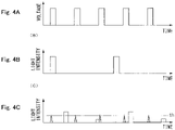
- Fig. 4A is a diagram showing an example of a drive voltage waveform of a heater of a comparative example.
- Fig. 4B is a diagram showing an example of a light intensity waveform of the laser light emitted from the object detection sensor 13 of the comparative example.
- Fig. 4C is a diagram showing an example of a light intensity waveform of the light received by the object detection sensor 13 of the comparative example.
- the comparative example here is an operation example where the drive voltage of the heater 16 is not associated with the emission time of the laser light emitted from the object detection sensor 13.
- Figs. 4A and 4B it is assumed that the drive voltage of the heater is intermittently supplied without being linked to the emission time of the laser light from the object detection sensor 13.
- Fig. 4C in order to remove noise (spike-like waveform) due to the drive voltage to the heater, for example, assuming that threshold level "th" that is set in accordance with the noise is established, the reflected light received at a light intensity lower than the threshold level would also be excluded. Therefore, there may be a case where it is not possible to detect the target object 2 existing in the distance.
- Fig. 5 is a flowchart showing the flow of operation by the heater driver of the controller. It should be noted that heat control by this heater driver is performed when the environmental temperature (ambient temperature of the vehicle lamp) detected by a temperature sensor (not shown) or the like becomes equal to or lower than a predetermined reference value, for example.
- the light emission time detection unit 41 of the heater driver 40 detects the rising edge (light emission time) of the light emission period of the laser light emitted from the object detection sensor 13 based on a detection signal from the optical sensor 14 (STEP S11).
- the drive voltage output unit 42 of the heater driver 40 sets start time of the drive voltage to the heater in accordance with the rising edge of the laser light detected by the light emission time detection unit 41 (STEP S12), and starts supply of the drive voltage (STEP S13).
- the time period until the end of the drive voltage supply is predetermined, it may be appropriately set by the drive voltage output unit.
- the process returns to STEP S11.
- the drive voltage is intermittently applied to the heater 16 at a cycle in accordance with the repeating cycle of the laser light.
- Fig. 6A is a diagram showing an example of a drive voltage waveform of the heater of a modified embodiment.
- Fig. 6B is a diagram showing an example of a light intensity waveform of the laser light emitted from the object detection sensor 13 of the modified embodiment.
- Fig. 6C is a diagram showing an example of a light intensity waveform of the light received by the object detection sensor 13 of the modified embodiment.
- supply of the drive voltage to the heater is started in accordance with the rising edge of the laser light of a first period
- supply of the drive voltage may be stopped in accordance with the rising edge of the laser light of a second period which arrives after the first period.
- the second laser light emission time is defined as the second period, but the present disclosure is not limited thereto, and the third laser light emission time or subsequent laser light emission time may be defined as the second period.
- the operation may be such that, supply of the drive voltage is started in accordance with the rising edge of the first laser light, the drive voltage is continuously supplied without being linked to the second laser light, then supply of the drive voltage is stopped in accordance with the rising edge of the third laser light. Since large noise due to the drive voltage supplied to the heater is generated at the rise (start time) of the drive voltage supply, as described above, the effect of the noise can be avoided as well by setting the start time and the stop time of the drive voltage supply in conjunction with the rising edge of the laser light (refer to Fig. 6C ).
- the controller 17 in which the heater driver 40 and the lamp driver 50 are integrated has been exemplified, but the heater driver 40 and the lamp driver 50 may be configured separately.
- a headlight is shown as an example of the vehicle lamp, but the vehicle lamp is not limited thereto, and a tail light may be used, for example.
Landscapes
- Engineering & Computer Science (AREA)
- Mechanical Engineering (AREA)
- Physics & Mathematics (AREA)
- General Engineering & Computer Science (AREA)
- Chemical & Material Sciences (AREA)
- Ceramic Engineering (AREA)
- Computer Networks & Wireless Communication (AREA)
- Electromagnetism (AREA)
- General Physics & Mathematics (AREA)
- Radar, Positioning & Navigation (AREA)
- Remote Sensing (AREA)
- Optical Radar Systems And Details Thereof (AREA)
Abstract
Description
- The present disclosure relates to a heater controller, heater control method, and a vehicle lamp.
-
Japanese Unexamined Patent Application Publication No. 2020-30908 - In recent years, in order to configure a driving support system or an automatic driving system, for example, an object detection sensor used for LiDAR (Light Detection And Ranging) technology, etc. is often installed in a vehicle.
- Here, consider a case where the above-described object detection sensor is built in a vehicle lamp. In this case, when the heater power is turned on, the energy at the rising edge of the current is electromagnetically radiated and thereby noise jumps into a drive circuit of the object detection sensor, which may have an adverse effect (for example, a decrease in detection accuracy).
- In a specific aspect, it is an object of the present disclosure to provide a technique capable of avoiding an adverse effect on a sensor by the heater.
-
- (1) A controller for a heater according to one aspect of the present disclosure is (a) a controller for a heater installed in a vehicle lamp, (b) where the controller detects a rising edge of a light emission period of a sensor light emitted from an object detection sensor built in the vehicle lamp, and starts supply of a drive voltage to the heater in accordance with the rising edge.
- (2) A vehicle lamp according to one aspect of the present disclosure is a vehicle lamp including: the controller for the heater described in the above (1), the heater controlled by the controller, and an object detection sensor.
- (3) A control method for a heater according to one aspect of the present disclosure is (a) a control method for a heater installed in a vehicle lamp, where the control method includes (b) to detect a rising edge of a light emission period of a sensor light emitted from an object detection sensor built in the vehicle lamp, and (c) to start supply of a drive voltage to the heater in accordance with the rising edge.
- According to the above configurations, it is possible to avoid an adverse effect on the sensor by the heater.
-
-
Fig. 1A is a schematic view of the appearance of a vehicle lamp of one embodiment as viewed from the front side. -
Fig. 1B is a diagram showing the internal structure of the vehicle lamp. -
Fig. 2 is a block diagram for explaining a configuration related to operation control of the vehicle lamp. -
Fig. 3A is a diagram showing an example of a drive voltage waveform of the heater. -
Fig. 3B is a diagram showing an example of a light intensity waveform of the laser light emitted from theobject detection sensor 13. -
Fig. 3C is a diagram showing an example of a light intensity waveform of the light received by theobject detection sensor 13. -
Fig. 4A is a diagram showing an example of a drive voltage waveform of a heater of a comparative example. -
Fig. 4B is a diagram showing an example of a light intensity waveform of the laser light emitted from theobject detection sensor 13 of the comparative example. -
Fig. 4C is a diagram showing an example of a light intensity waveform of the light received by theobject detection sensor 13 of the comparative example. -
Fig. 5 is a flowchart showing the flow of operation by the heater driver of the controller. -
Fig. 6A is a diagram showing an example of a drive voltage waveform of the heater of a modified embodiment. -
Fig. 6B is a diagram showing an example of a light intensity waveform of the laser light emitted from theobject detection sensor 13 of the modified embodiment. -
Fig. 6C is a diagram showing an example of a light intensity waveform of the light received by theobject detection sensor 13 of the modified embodiment. -
Fig. 1A is a schematic view of the appearance of a vehicle lamp of one embodiment as viewed from the front side.Fig. 1B is a diagram showing the internal structure of the vehicle lamp, and is a view ofFig. 1A cut along a horizontal plane and viewed from above. Thevehicle lamp 1 of the present embodiment shown in each figure is arranged at the front of the vehicle and used as a headlight, for example. Here, only onevehicle lamp 1 arranged either on the left or right side is shown. Thevehicle lamp 1 is configured to include ahousing 10, anouter lens 11, alamp unit 12, anobject detection sensor 13, anoptical sensor 14, anoptical filter 15, aheater 16, and acontroller 17. - The
housing 10 houses thelamp unit 12, theobject detection sensor 13, theoptical sensor 14, theoptical filter 15, theheater 16, and thecontroller 17 of thevehicle lamp 1, and is configured by using an appropriate material such as plastic. - The
outer lens 11 is a front cover attached to thehousing 10, and protects each of thelamp unit 12 and the like arranged inside thehousing 10. Theouter lens 11 is formed of a material that transmits light. - The
lamp unit 12 is arranged in thehousing 10, and is turned on and off under the control of thecontroller 17. The light from thelamp unit 12 is emitted to the outside through theouter lens 11 and is irradiated to the front of the vehicle. - The
object detection sensor 13 emits pulsed laser light (sensor light) while scanning a wide range in front of the vehicle, and detects the shape of a target object and the relative distance to the target object by detecting the reflected light obtained by reflecting the laser light on the surface of the target object. In this embodiment, a LiDAR (Light Detection and Ranging/Laser Imaging Detection and Ranging) device is used as theobject detection sensor 13. The laser light emitted from theobject detection sensor 13 of the present embodiment is, for example, a laser light having a near infrared wavelength of about 750 nm to 1.5 µm. - The
optical sensor 14 is provided at a position where a part of the laser light emitted from theobject detection sensor 13 can be incident, such as the front side of theobject detection sensor 13, detects the incident laser light and outputs to the controller 17 a detection signal according to the incident laser light intensity. - The
optical filter 15 is a bandpass filter that transmits light of a specific wavelength and attenuates light of other wavelengths. As theoptical filter 15 of the present embodiment, a bandpass filter set to transmit light in accordance with the wavelength of the laser light of theobject detection sensor 13 and attenuate light of other wavelengths, particularly far infrared wavelengths (for example, 3.0 µm to 1 mm) emitted from theheater 16, is used. - The
heater 16 is for generating heat in order to prevent snow accretion or the like on theouter lens 11. Theheater 16 is arranged, for example, inside theouter lens 11 as shown in the figure, at least in a range in accordance with the emission range of the laser light of theobject detection sensor 13. As theheater 16, at least a conductive film having high transparency to the laser light emitted by theobject detection sensor 13 is used. For example, it is preferable to configure theheater 16 by using a ZnO film having high conductivity and high light transmittance over a wide band as disclosed inJapanese Unexamined Patent Application Publication No. 2017-133079 - The
controller 17 controls turning on and off of thelamp unit 12 and controls the operation of theheater 16. Thecontroller 17 is connected to each of thelamp unit 12, theoptical sensor 14, and theheater 16. Thecontroller 17 is realized by using, for example, a computer having a CPU (Central Processing Unit), a ROM (Read Only Memory), a RAM (Random Access Memory), and the like, and executing a predetermined operation program on the computer. -
Fig. 2 is a block diagram for explaining a configuration related to operation control of the vehicle lamp. As shown in the figure, theobject detection sensor 13 is configured to include alight emitting unit 31, alight receiving unit 32, and acontrol circuit 33. Further, thecontroller 17 is configured to include aheater driver 40 and alamp driver 50. Theheater driver 40 is configured to include a light emissiontime detection unit 41 and a drivevoltage output unit 42. - The
light emitting unit 31 of theobject detection sensor 13 emits laser light while scanning in a two-dimensional direction or a three-dimensional direction. A part of the emitted laser light is detected by theoptical sensor 14. The position of theoptical sensor 14 is preferably a position that does not affect the scanning of the laser light by thelight emitting unit 31. The emitted laser light passes through theoptical filter 15 and theheater 16 and is emitted to the outside, and is reflected by thetarget object 2. - The
light receiving unit 32 of theobject detection sensor 13 receives the light reflected by thetarget object 2 and outputs a detection signal according to its intensity. Thecontrol circuit 33 controls the operation of thelight emitting unit 31, and based on the intensity of the reflected light received by thelight receiving unit 32 and the timing thereof, generates a distance image that includes distance with respect to thetarget body 2 and the shape, etc., of thetarget body 2. The generated distance image data is supplied to a higher-level device which is not shown in the figure. - The
heater driver 40 controls the operation of theheater 16. Thelamp driver 50 controls turning on and off of thelamp unit 12. - The light emission
time detection unit 41 of theheater driver 40 detects the rising edge (light emission time) of the light emission period of the laser light emitted from theobject detection sensor 13 based on the detection signal from theoptical sensor 14. The drivevoltage output unit 42 starts supply of drive voltage to the heater in accordance with the rising edge of the laser light detected by the light emissiontime detection unit 41. -
Fig. 3A is a diagram showing an example of a drive voltage waveform of the heater.Fig. 3B is a diagram showing an example of a light intensity waveform of the laser light emitted from theobject detection sensor 13.Fig. 3C is a diagram showing an example of a light intensity waveform of the light received by theobject detection sensor 13. - As shown in
Fig. 3B , the laser light emitted from theobject detection sensor 13 is intermittently and repeatedly emitted at regular intervals. The pulse width W and the repetition period T of the laser light are appropriately set according to the distance resolution, the maximum detection distance, and the like. For example, if the distance resolution is 75 cm, the pulse width W is set to 5 ns, and if the maximum detection distance is 200 m, the repetition period T is set to 40 ms (which corresponds to 25 Hz) which includes the internal processing time, etc. Further, as shown inFig. 3C , in order to prevent erroneous detection when detecting the reflected light, a reception blank period B, which is a period in which the reflected light is ignored within a certain period from the emission time of the laser light, is provided. This reception blank period B is set to a period of 10 ns starting from the emission time of the laser light, for example. - In response to such operation of the
object detection sensor 13, the light emissiontime detection unit 41 of theheater driver 40 detects the rising edge of the laser light using the detection signal output from theoptical sensor 14. In accordance with the rising edge that is detected, as shown inFig. 3A , the drivevoltage output unit 42 starts supply of drive voltage to theheater 16. As shown, the drive voltage is repeatedly supplied every time the laser light is emitted. By increasing or decreasing the number of repetitions or intermittently supplying the drive voltage, the temperature of theheater 16 can be controlled. - As a result, even if noise (waveform shown in a spike shape in
Fig. 3C ) due to electromagnetic radiation of energy accompanying the start of drive voltage supply to theheater 16 jumps into the receivingunit 32 of theobject detection sensor 13, since it is within the above-described reception blank period, it can be removed as noise. Therefore, it is possible to detect thetarget object 2 even when the light intensity of the reflected light is low. - Here, note that "in accordance with the rising edge" means that after the rising edge of the laser light is detected, drive voltage supply is started after an extremely small delay time. Generally, it can be said that it is synchronized with the rising edge, but in principle, it does not mean that the rising edge and the start time of the drive voltage supply are exactly the same.
- Further, as shown in
Fig. 3A , after starting supply of the drive voltage, the drivevoltage output unit 42 stops supply of the drive voltage at an appropriate time before the reception blank period B elapses. In the illustrated example, the drive voltage supply is stopped at about the same time as the end of the reception blank period B. -
Fig. 4A is a diagram showing an example of a drive voltage waveform of a heater of a comparative example.Fig. 4B is a diagram showing an example of a light intensity waveform of the laser light emitted from theobject detection sensor 13 of the comparative example.Fig. 4C is a diagram showing an example of a light intensity waveform of the light received by theobject detection sensor 13 of the comparative example. The comparative example here is an operation example where the drive voltage of theheater 16 is not associated with the emission time of the laser light emitted from theobject detection sensor 13. - As shown in
Figs. 4A and 4B , it is assumed that the drive voltage of the heater is intermittently supplied without being linked to the emission time of the laser light from theobject detection sensor 13. In this case, as shown inFig. 4C , in order to remove noise (spike-like waveform) due to the drive voltage to the heater, for example, assuming that threshold level "th" that is set in accordance with the noise is established, the reflected light received at a light intensity lower than the threshold level would also be excluded. Therefore, there may be a case where it is not possible to detect thetarget object 2 existing in the distance. -
Fig. 5 is a flowchart showing the flow of operation by the heater driver of the controller. It should be noted that heat control by this heater driver is performed when the environmental temperature (ambient temperature of the vehicle lamp) detected by a temperature sensor (not shown) or the like becomes equal to or lower than a predetermined reference value, for example. - The light emission
time detection unit 41 of theheater driver 40 detects the rising edge (light emission time) of the light emission period of the laser light emitted from theobject detection sensor 13 based on a detection signal from the optical sensor 14 (STEP S11). - Next, the drive
voltage output unit 42 of theheater driver 40 sets start time of the drive voltage to the heater in accordance with the rising edge of the laser light detected by the light emission time detection unit 41 (STEP S12), and starts supply of the drive voltage (STEP S13). Here, although the time period until the end of the drive voltage supply is predetermined, it may be appropriately set by the drive voltage output unit. - Thereafter, the process returns to STEP S11. As a result, the drive voltage is intermittently applied to the
heater 16 at a cycle in accordance with the repeating cycle of the laser light. -
Fig. 6A is a diagram showing an example of a drive voltage waveform of the heater of a modified embodiment.Fig. 6B is a diagram showing an example of a light intensity waveform of the laser light emitted from theobject detection sensor 13 of the modified embodiment.Fig. 6C is a diagram showing an example of a light intensity waveform of the light received by theobject detection sensor 13 of the modified embodiment. As shown inFigs. 6A and 6B , after supply of the drive voltage to the heater is started in accordance with the rising edge of the laser light of a first period, supply of the drive voltage may be stopped in accordance with the rising edge of the laser light of a second period which arrives after the first period. In this case, in the illustrated example, the second laser light emission time is defined as the second period, but the present disclosure is not limited thereto, and the third laser light emission time or subsequent laser light emission time may be defined as the second period. For example, the operation may be such that, supply of the drive voltage is started in accordance with the rising edge of the first laser light, the drive voltage is continuously supplied without being linked to the second laser light, then supply of the drive voltage is stopped in accordance with the rising edge of the third laser light. Since large noise due to the drive voltage supplied to the heater is generated at the rise (start time) of the drive voltage supply, as described above, the effect of the noise can be avoided as well by setting the start time and the stop time of the drive voltage supply in conjunction with the rising edge of the laser light (refer toFig. 6C ). - According to the above embodiments, it is possible to avoid an adverse effect on the sensor by the heater.
- It should be noted that the present disclosure is not limited to the subject matter of the foregoing embodiment, and can be implemented by being variously modified within the scope of the present disclosure as defined by the appended claims. For example, in the above-described embodiments, rising edge of the laser light is detected by using the
optical sensor 14, but if a signal indicating the rising edge can be obtained directly from theobject detection sensor 13, the signal may be used to perform rising edge detection operation in the emissiontime detection unit 41 of thecontroller 17. - Further, in the above-described embodiments, the
controller 17 in which theheater driver 40 and thelamp driver 50 are integrated has been exemplified, but theheater driver 40 and thelamp driver 50 may be configured separately. - Further, in the above-described embodiment, a headlight is shown as an example of the vehicle lamp, but the vehicle lamp is not limited thereto, and a tail light may be used, for example.
- The present application is based on, and claims priority from,
JP Application Serial Number, 2021-099712 filed on June 15, 2021 -
- 1:Vehicle lamp
- 10:Housing
- 11: Outer lens
- 12:Lamp unit
- 13:Object detection sensor
- 14:Optical sensor
- 15:Optical filter
- 16:Heater
- 17:Controller
- 31:Light emitting unit
- 32:Light receiving unit
- 33:Control circuit
- 40:Heater driver
- 41:Light emission time detection unit
- 42:Drive voltage output unit
- 50:Lamp driver
Claims (9)
- A controller for a heater installed in a vehicle lamp,
wherein the controller detects a rising edge of a light emission period of a sensor light emitted from an object detection sensor built in the vehicle lamp, and starts supply of a drive voltage to the heater in accordance with the rising edge. - The controller for the heater according to claim 1,
wherein the controller comprises:a detection unit that detects the rising edge, anda feeding unit that supplies the drive voltage. - The controller for the heater according to claim 1 or 2,
wherein the controller further comprises an optical sensor that detects the intensity of the sensor light, and detects the rising edge based on a detection signal from the optical sensor. - The controller for the heater according to any one of claims 1 to 3,
wherein the sensor light is intermittently and repeatedly emitted, and the drive voltage is supplied every time the sensor light is emitted. - The controller for the heater according to claim 4,
wherein, after the sensor light is emitted, supply of the drive voltage is stopped until a time that corresponds to the minimum detection distance of the object detection sensor elapses. - The controller for the heater according to claim 4,
wherein supply of the drive voltage is started in accordance with the rising edge of a first period, and the supply is stopped in accordance with the rising edge of a second period which arrives after the first period. - The controller for the heater according to any one of claims 1 to 6,
wherein the heater is a ZnO film provided inside the front cover of the vehicle lamp. - A vehicle lamp comprising:the controller for the heater according to any one of claims 1 to 7,the heater controlled by the controller, andan object detection sensor.
- A control method for a heater installed in a vehicle lamp,
wherein the control method for the heater includes to detect a rising edge of a light emission period of a sensor light emitted from an object detection sensor built in the vehicle lamp, and to start supply of a drive voltage to the heater in accordance with the rising edge.
Applications Claiming Priority (1)
| Application Number | Priority Date | Filing Date | Title |
|---|---|---|---|
| JP2021099712A JP7699477B2 (en) | 2021-06-15 | 2021-06-15 | HEATER CONTROL DEVICE, HEATER CONTROL METHOD, AND VEHICLE LAMP |
Publications (1)
| Publication Number | Publication Date |
|---|---|
| EP4106489A1 true EP4106489A1 (en) | 2022-12-21 |
Family
ID=82067606
Family Applications (1)
| Application Number | Title | Priority Date | Filing Date |
|---|---|---|---|
| EP22179106.4A Withdrawn EP4106489A1 (en) | 2021-06-15 | 2022-06-15 | Heater controller, heater control method, vehicle lamp |
Country Status (3)
| Country | Link |
|---|---|
| US (1) | US12538385B2 (en) |
| EP (1) | EP4106489A1 (en) |
| JP (1) | JP7699477B2 (en) |
Families Citing this family (1)
| Publication number | Priority date | Publication date | Assignee | Title |
|---|---|---|---|---|
| US12345388B2 (en) * | 2020-06-12 | 2025-07-01 | Motherson Innovations Company Limited | Functional means for imaging device, lighting module, rear view devices, driving assistance system and vehicle |
Citations (4)
| Publication number | Priority date | Publication date | Assignee | Title |
|---|---|---|---|---|
| US20190017677A1 (en) * | 2017-07-12 | 2019-01-17 | Valeo North America, Inc. | Heater plate for vehicle light heating |
| JP2020030908A (en) | 2018-08-21 | 2020-02-27 | 株式会社小糸製作所 | Heater system and heater system control method |
| US20210116544A1 (en) * | 2018-07-02 | 2021-04-22 | Denso Corporation | Distance measuring device |
| DE112019004439T5 (en) * | 2018-09-05 | 2021-05-20 | Denso Corporation | DISTANCE MEASURING DEVICE |
Family Cites Families (7)
| Publication number | Priority date | Publication date | Assignee | Title |
|---|---|---|---|---|
| JPS62168485U (en) * | 1986-04-16 | 1987-10-26 | ||
| JP3253793B2 (en) * | 1994-02-15 | 2002-02-04 | 敏英 三宅 | Active ranging device |
| JP3690029B2 (en) * | 1997-01-22 | 2005-08-31 | 株式会社デンソー | Distance measuring device |
| JP3783330B2 (en) * | 1997-05-13 | 2006-06-07 | 株式会社日本自動車部品総合研究所 | Raindrop detection device |
| JP6627536B2 (en) | 2016-01-29 | 2020-01-08 | 日本製鉄株式会社 | Steel with excellent toughness in weld heat affected zone and method of manufacturing steel with excellent toughness in weld heat affected zone |
| US10351103B2 (en) | 2017-09-29 | 2019-07-16 | Aptiv Technologies Limited | LIDAR device with heated cover useful for automated vehicles |
| WO2021095666A1 (en) | 2019-11-11 | 2021-05-20 | 株式会社小糸製作所 | Vehicle lighting fixture, vehicle system, and method executed in said vehicle system |
-
2021
- 2021-06-15 JP JP2021099712A patent/JP7699477B2/en active Active
-
2022
- 2022-06-14 US US17/839,504 patent/US12538385B2/en active Active
- 2022-06-15 EP EP22179106.4A patent/EP4106489A1/en not_active Withdrawn
Patent Citations (4)
| Publication number | Priority date | Publication date | Assignee | Title |
|---|---|---|---|---|
| US20190017677A1 (en) * | 2017-07-12 | 2019-01-17 | Valeo North America, Inc. | Heater plate for vehicle light heating |
| US20210116544A1 (en) * | 2018-07-02 | 2021-04-22 | Denso Corporation | Distance measuring device |
| JP2020030908A (en) | 2018-08-21 | 2020-02-27 | 株式会社小糸製作所 | Heater system and heater system control method |
| DE112019004439T5 (en) * | 2018-09-05 | 2021-05-20 | Denso Corporation | DISTANCE MEASURING DEVICE |
Also Published As
| Publication number | Publication date |
|---|---|
| JP7699477B2 (en) | 2025-06-27 |
| US20220400534A1 (en) | 2022-12-15 |
| US12538385B2 (en) | 2026-01-27 |
| JP2022191079A (en) | 2022-12-27 |
Similar Documents
| Publication | Publication Date | Title |
|---|---|---|
| EP3064957B1 (en) | Semiconductor laser driving apparatus, optical scanning apparatus, object detection apparatus, and mobile apparatus | |
| KR102096676B1 (en) | 2-dimensioal lidar scanner and control device using for vehicle | |
| KR102393439B1 (en) | Lidar apparatus for vehicle | |
| US12377817B2 (en) | Ranging device | |
| US10179535B2 (en) | Lighting control device of vehicle headlamp and vehicle headlamp system | |
| US20220400534A1 (en) | Heater controller, heater control method, vehicle lamp | |
| JP4423951B2 (en) | LED lamp device with distance measuring function | |
| CN112956034B (en) | Optical module and distance measuring device | |
| WO2019163526A1 (en) | Measuring device, control method, program, and storage medium | |
| JP2006021720A (en) | Lamp device with distance measurement function | |
| JP4284652B2 (en) | Radar equipment | |
| JP6417981B2 (en) | Ranging device | |
| JP6566198B2 (en) | Object detection device, sensing device, mobile device, and object detection method | |
| JPWO2020022206A1 (en) | Distance measuring device | |
| JP2005257323A (en) | Distance detector | |
| JP4033036B2 (en) | Inter-vehicle distance detector | |
| JP7746300B2 (en) | Gating cameras, vehicle sensing systems, vehicle lighting fixtures | |
| JP4221663B2 (en) | Radar equipment | |
| JP2006038686A (en) | Lamp device with distance measurement function | |
| CN113167874A (en) | Time-of-flight sensor and monitoring system comprising such a sensor | |
| CN114636998B (en) | Active distance measuring device and active distance measuring method | |
| EP4201745A1 (en) | Automotive sensing system and gating camera | |
| WO2021065437A1 (en) | Ranging device | |
| US20220355723A1 (en) | Illumination and detection lamp assembly and vehicle | |
| CN217428373U (en) | Rearview mirror frost detection structure |
Legal Events
| Date | Code | Title | Description |
|---|---|---|---|
| PUAI | Public reference made under article 153(3) epc to a published international application that has entered the european phase |
Free format text: ORIGINAL CODE: 0009012 |
|
| STAA | Information on the status of an ep patent application or granted ep patent |
Free format text: STATUS: THE APPLICATION HAS BEEN PUBLISHED |
|
| AK | Designated contracting states |
Kind code of ref document: A1 Designated state(s): AL AT BE BG CH CY CZ DE DK EE ES FI FR GB GR HR HU IE IS IT LI LT LU LV MC MK MT NL NO PL PT RO RS SE SI SK SM TR |
|
| STAA | Information on the status of an ep patent application or granted ep patent |
Free format text: STATUS: REQUEST FOR EXAMINATION WAS MADE |
|
| 17P | Request for examination filed |
Effective date: 20230620 |
|
| RBV | Designated contracting states (corrected) |
Designated state(s): AL AT BE BG CH CY CZ DE DK EE ES FI FR GB GR HR HU IE IS IT LI LT LU LV MC MK MT NL NO PL PT RO RS SE SI SK SM TR |
|
| STAA | Information on the status of an ep patent application or granted ep patent |
Free format text: STATUS: THE APPLICATION IS DEEMED TO BE WITHDRAWN |
|
| 18D | Application deemed to be withdrawn |
Effective date: 20260103 |