EP4106451A1 - Downlink control information design method and system, electronic device and storage medium - Google Patents
Downlink control information design method and system, electronic device and storage medium Download PDFInfo
- Publication number
- EP4106451A1 EP4106451A1 EP21753015.3A EP21753015A EP4106451A1 EP 4106451 A1 EP4106451 A1 EP 4106451A1 EP 21753015 A EP21753015 A EP 21753015A EP 4106451 A1 EP4106451 A1 EP 4106451A1
- Authority
- EP
- European Patent Office
- Prior art keywords
- dci
- state information
- tci state
- control channel
- information
- Prior art date
- Legal status (The legal status is an assumption and is not a legal conclusion. Google has not performed a legal analysis and makes no representation as to the accuracy of the status listed.)
- Pending
Links
Images


Classifications
-
- H—ELECTRICITY
- H04—ELECTRIC COMMUNICATION TECHNIQUE
- H04L—TRANSMISSION OF DIGITAL INFORMATION, e.g. TELEGRAPHIC COMMUNICATION
- H04L5/00—Arrangements affording multiple use of the transmission path
- H04L5/003—Arrangements for allocating sub-channels of the transmission path
- H04L5/0053—Allocation of signalling, i.e. of overhead other than pilot signals
-
- H—ELECTRICITY
- H04—ELECTRIC COMMUNICATION TECHNIQUE
- H04L—TRANSMISSION OF DIGITAL INFORMATION, e.g. TELEGRAPHIC COMMUNICATION
- H04L5/00—Arrangements affording multiple use of the transmission path
- H04L5/003—Arrangements for allocating sub-channels of the transmission path
- H04L5/0048—Allocation of pilot signals, i.e. of signals known to the receiver
- H04L5/0051—Allocation of pilot signals, i.e. of signals known to the receiver of dedicated pilots, i.e. pilots destined for a single user or terminal
-
- H—ELECTRICITY
- H04—ELECTRIC COMMUNICATION TECHNIQUE
- H04W—WIRELESS COMMUNICATION NETWORKS
- H04W72/00—Local resource management
- H04W72/20—Control channels or signalling for resource management
-
- H—ELECTRICITY
- H04—ELECTRIC COMMUNICATION TECHNIQUE
- H04L—TRANSMISSION OF DIGITAL INFORMATION, e.g. TELEGRAPHIC COMMUNICATION
- H04L1/00—Arrangements for detecting or preventing errors in the information received
- H04L1/12—Arrangements for detecting or preventing errors in the information received by using return channel
- H04L1/16—Arrangements for detecting or preventing errors in the information received by using return channel in which the return channel carries supervisory signals, e.g. repetition request signals
- H04L1/18—Automatic repetition systems, e.g. Van Duuren systems
- H04L1/1812—Hybrid protocols; Hybrid automatic repeat request [HARQ]
-
- H—ELECTRICITY
- H04—ELECTRIC COMMUNICATION TECHNIQUE
- H04L—TRANSMISSION OF DIGITAL INFORMATION, e.g. TELEGRAPHIC COMMUNICATION
- H04L5/00—Arrangements affording multiple use of the transmission path
- H04L5/0001—Arrangements for dividing the transmission path
- H04L5/0014—Three-dimensional division
- H04L5/0023—Time-frequency-space
-
- H—ELECTRICITY
- H04—ELECTRIC COMMUNICATION TECHNIQUE
- H04L—TRANSMISSION OF DIGITAL INFORMATION, e.g. TELEGRAPHIC COMMUNICATION
- H04L5/00—Arrangements affording multiple use of the transmission path
- H04L5/003—Arrangements for allocating sub-channels of the transmission path
- H04L5/0053—Allocation of signalling, i.e. of overhead other than pilot signals
- H04L5/0055—Physical resource allocation for ACK/NACK
-
- H—ELECTRICITY
- H04—ELECTRIC COMMUNICATION TECHNIQUE
- H04W—WIRELESS COMMUNICATION NETWORKS
- H04W72/00—Local resource management
- H04W72/20—Control channels or signalling for resource management
- H04W72/23—Control channels or signalling for resource management in the downlink direction of a wireless link, i.e. towards a terminal
-
- H—ELECTRICITY
- H04—ELECTRIC COMMUNICATION TECHNIQUE
- H04L—TRANSMISSION OF DIGITAL INFORMATION, e.g. TELEGRAPHIC COMMUNICATION
- H04L1/00—Arrangements for detecting or preventing errors in the information received
- H04L1/12—Arrangements for detecting or preventing errors in the information received by using return channel
- H04L1/16—Arrangements for detecting or preventing errors in the information received by using return channel in which the return channel carries supervisory signals, e.g. repetition request signals
- H04L1/18—Automatic repetition systems, e.g. Van Duuren systems
- H04L1/1829—Arrangements specially adapted for the receiver end
- H04L1/1861—Physical mapping arrangements
Definitions
- the disclosure relates to the technical field of wireless communication, and in particular, to a method and a system for downlink control information (DCI) design, an electronic device, and a storage medium.
- DCI downlink control information
- transmission configuration indicator (TCI) state information of a control channel is obtained according to a TCI state of a control resource set (CORESET) associated with the control channel.
- TCI state information of the CORESET is configured through radio resource control (RRC) or through the RRC and a medium access control (MAC) control element (CE).
- RRC radio resource control
- MAC medium access control
- a list of candidate TCI states may be configured through the RRC. If only one TCI state is configured through the RRC, the MAC CE is not required for configuration. If more than one TCI state is configured through the RRC, the MAC CE is required for selection and configuration of a TCI state from these TCI states.
- a technical problem to be solved by the disclosure is to overcome a defect that a manner of configuring TCI state information of a control channel in related art is likely to cause a large delay, and a purpose of the disclosure is to provide a method and a system for DCI design, an electronic device, and a storage media.
- the disclosure solves the above-mentioned technical problem with the following technical solution.
- the disclosure provides a method for DCI design.
- the method includes: configuring TCI state information of a control channel through a DCI.
- configuring the TCI state information of the control channel through the DCI includes: indicating TCI state information of each first CORESET corresponding to each information block in the common DCI dynamically, and/or indicating TCI state information of each first physical uplink control channel (PUCCH) resource corresponding to each information block in the common DCI dynamically, where each user equipment (UE) corresponds to one information block.
- PUCCH physical uplink control channel
- the method for design further includes: determining a first valid time corresponding to the configured TCI state information, where the first valid time is calculated according to a time slot in which a physical downlink control channel (PDCCH) is received and a predefined time sequence.
- PDCCH physical downlink control channel
- configuring the TCI state information of the control channel through the DCI includes: indicating TCI state information of each second CORESET corresponding to the dedicated DCI dynamically, and/or indicating TCI state information of each second PUCCH resource corresponding to the dedicated DCI dynamically, where the dedicated DCI corresponds to one UE.
- the method for design further includes: determining a second valid time corresponding to the configured TCI state information, where the second valid time is calculated according to a time slot in which a PDCCH is received and a predefined time sequence, or the second valid time is a time when the UE transmits a feedback signal to a network-side device.
- the feedback signal transmitted by the UE to the network-side device includes hybrid automatic repeat request (HARQ)-acknowledgement (ACK) feedback information generated by the UE based on the received DCI.
- HARQ hybrid automatic repeat request
- ACK acknowledgenowledgement
- the method further includes: when configuration of the TCI state information of the control channel through a MAC CE is valid, determining that configuration or a configuration manner of the TCI state information of the control channel through the DCI is invalid, and determining the TCI state information configured through the MAC CE as the TCI state information of the control channel.
- the disclosure also provides a system for DCI design.
- the system for design includes an information configuration module.
- the information configuration module is configured to configure TCI state information of a control channel through a DCI.
- the information configuration module is configured to: indicate TCI state information of each first CORESET corresponding to each information block in the common DCI dynamically, and/or indicate TCI state information of each first PUCCH resource corresponding to each information block in the common DCI dynamically, where each UE corresponds to one information block.
- the system for design further includes a first determination module.
- the first determination module is configured to: determine a first valid time corresponding to the configured TCI state information, where the first valid time is calculated according to a time slot in which a PDCCH is received and a predefined time sequence.
- the information configuration module is configured to: indicate TCI state information of each second CORESET corresponding to the dedicated DCI dynamically, and/or indicate TCI state information of each second PUCCH resource corresponding to the dedicated DCI dynamically, where the dedicated DCI corresponds to one UE.
- the system for design further includes a second determination module.
- the second determination module is configured to: determine a second valid time corresponding to the configured TCI state information, where the second valid time is calculated according to a time slot in which a PDCCH is received and a predefined time sequence, or the second valid time is a time when the UE transmits a feedback signal to a network-side device.
- the feedback signal transmitted by the UE to the network-side device includes HARQ-ACK feedback information generated by the UE based on the received DCI.
- the system for design further includes a third determination module.
- the third determination module is configured to: when configuration of the TCI state information of the control channel through a MAC CE is valid, determine that configuration or a configuration manner of the TCI state information of the control channel through the DCI is invalid, and determine the TCI state information configured through the MAC CE as the TCI state information of the control channel.
- the disclosure also provides an electronic device.
- the electronic device includes a processor and a memory configured to store computer programs executable by the processor.
- the computer programs when executed by the processor, are configured to perform the method for DCI design described above.
- the disclosure also provides a computer-readable storage medium storing computer programs which, when executed by a processor, are configured to perform operations of the method for DCI design described above.
- the TCI state information of the control channel is configured (indicated or updated) through the DCI, including a common DCI and/or a dedicated DCI, thereby solving a problem that a related protocol does not support indicating TCI state information of a CORESET and/or a PUCCH resource through a DCI, overcoming a problem of large delay of a related configuration manner, and improving efficiency, practicability, and effectiveness of configuration.
- a method for DCI design in this embodiment includes the following.
- S101 includes the following.
- S1012 Determine a first valid time corresponding to the configured TCI state information, where the first valid time is calculated according to a time slot in which a PDCCH is received and a predefined time sequence.
- the common DCI includes multiple information blocks, and each information block corresponds to a user and multiple CORESETs. Specifically, each information block contains TCI information in some or all of the CORESETs allocated to the user.
- the number of information blocks corresponding to the common DCI and the number of CORESETs corresponding to each information block are preset through network configuration, and can also be adjusted according to an actual situation.
- the common DCI includes multiple information blocks, and each information block corresponds to a user and multiple PUCCH resources or PUCCH resource groups. Specifically, each information block contains TCI information in some or all of the PUCCH resources/resource groups allocated to the user.
- the number of information blocks corresponding to the common DCI and the number of PUCCH resources/resource groups corresponding to each information block are preset through network configuration, and can also be adjusted according to an actual situation.
- the configuration or the configuration manner of the TCI state information of the control channel through the DCI is invalid, and the TCI state information configured through the MAC CE is used as the TCI state information of the control channel.
- the TCI state information of the control channel is configured through the common DCI, thereby solving a problem that a related protocol does not support indicating TCI state information of a CORESET and/or a PUCCH resource through a DCI, overcoming a problem of large delay of a related configuration manner, and improving efficiency, practicability, and effectiveness of configuration.
- a method for DCI design in this embodiment includes the following.
- S101 includes the following.
- S1015 Determine a second valid time corresponding to the configured TCI state information, where the second valid time is calculated according to a time slot in which a PDCCH is received and a predefined time sequence, or the second valid time is a time when the UE transmits a feedback signal to a network-side device.
- the feedback signal includes but is not limited to HARQ-ACK feedback information generated by the UE based on the received DCI.
- the DCI includes TCI for CORESET 0, TCI for CORESET 1, ...TCI for CORESET M.
- the dedicated DCI corresponds to multiple CORESETs, the number of CORESETs allocated to the terminal is M+1, and M is a natural number.
- the number of CORESETs corresponding to the dedicated DCI is preset through network configuration, and can also be adjusted according to an actual situation.
- the DCI includes TCI for PUCCH 0, TCI for PUCCH 1, ... TCI for PUCCH N.
- the dedicated DCI corresponds to multiple PUCCH resources or PUCCH resource groups, the number of PUCCH resources or PUCCH resource groups allocated to the terminal is N+1, and N is a natural number.
- the number of PUCCH resources or PUCCH resource groups corresponding to the dedicated DCI is preset through network configuration, and can also be adjusted according to an actual situation.
- n represents the time slot of the PDCCH
- k represents the predefined time sequence, which is pre-configured by the network and can also be adjusted according to an actual situation
- the valid time t of the configured TCI state is a time when the UE transmits an ACK/NACK (a feedback signal) to a network-side device.
- the configuration or the configuration manner of the TCI state information of the control channel through the DCI is invalid, and the TCI state information configured through the MAC CE is used as the TCI state information of the control channel.
- the TCI state information of the control channel is configured through the dedicated DCI, thereby solving a problem that a related protocol does not support indicating TCI state information of a CORESET and/or a PUCCH resource through a DCI, overcoming a problem of large delay of a related configuration manner, and improving efficiency, practicability, and effectiveness of configuration.
- a system for DCI design in this embodiment includes an information configuration module 1, a first determination module 2, and a third determination module 3.
- the information configuration module 1 is configured to configure TCI state information of a control channel through a DCI, which specifically includes indicating or updating the TCI state information of the control channel through the DCI.
- the information configuration module 1 is configured to indicate TCI state information of each first CORESET corresponding to each information block in the common DCI dynamically, and/or indicate TCI state information of each first PUCCH resource corresponding to each information block in the common DCI dynamically, where each UE corresponds to one information block.
- the first determination module 2 is configured to determine a first valid time corresponding to the configured TCI state information, where the first valid time is calculated according to a time slot in which a PDCCH is received and a predefined time sequence.
- the third determination module 3 is configured to, when configuration of the TCI state information of the control channel through a MAC CE is valid, determine that configuration or a configuration manner of the TCI state information of the control channel through the DCI is invalid, and determine the TCI state information configured through the MAC CE as the TCI state information of the control channel.
- the common DCI includes multiple information blocks, and each information block corresponds to a user and multiple CORESETs. Specifically, each information block contains TCI information in some or all of the CORESETs allocated to the user.
- the number of information blocks corresponding to the common DCI and the number of CORESETs corresponding to each information block are preset through network configuration, and can also be adjusted according to an actual situation.
- the common DCI includes multiple information blocks, and each information block corresponds to a user and multiple PUCCH resources or PUCCH resource groups. Specifically, each information block contains TCI information in some or all of the PUCCH resources/resource groups allocated to the user.
- the number of information blocks corresponding to the common DCI and the number of PUCCH resources/resource groups corresponding to each information block are preset through network configuration, and can also be adjusted according to an actual situation.
- the configuration or the configuration manner of the TCI state information of the control channel through the DCI is invalid, and the TCI state information configured through the MAC CE is used as the TCI state information of the control channel.
- the TCI state information of the control channel is configured through the common DCI, thereby solving a problem that a related protocol does not support indicating TCI state information of a CORESET and/or a PUCCH resource through a DCI, overcoming a problem of large delay of a related configuration manner, and improving efficiency, practicability, and effectiveness of configuration.
- a system for DCI design in this embodiment includes an information configuration module 1, a second determination module 4, and a third determination module 3.
- the information configuration module 1 is configured to configure TCI state information of a control channel through a DCI, which specifically includes indicating or updating the TCI state information of the control channel through the DCI.
- the information configuration module 1 is configured to indicate TCI state information of each second CORESET corresponding to the dedicated DCI dynamically, and/or indicate TCI state information of each second PUCCH resource corresponding to the dedicated DCI dynamically, where the dedicated DCI corresponds to a certain UE.
- the second determination module 4 is configured to determine a second valid time corresponding to the configured TCI state information, where the second valid time is calculated according to a time slot in which a PDCCH is received and a predefined time sequence, or the second valid time is a time when the UE transmits a feedback signal to a network-side device.
- the feedback signal includes but is not limited to HARQ-ACK feedback information generated by the UE based on the received DCI.
- the third determination module 3 is configured to, when configuration of the TCI state information of the control channel through a MAC CE is valid, determine that configuration or a configuration manner of the TCI state information of the control channel through the DCI is invalid, and determine the TCI state information configured through the MAC CE as the TCI state information of the control channel.
- the DCI includes TCI for CORESET 0, TCI for CORESET 1, ...TCI for CORESET M.
- the dedicated DCI corresponds to multiple CORESETs, the number of CORESETs allocated to the terminal is M+1, and M is a natural number.
- the number of CORESETs corresponding to the dedicated DCI is preset through network configuration, and can also be adjusted according to an actual situation.
- the DCI includes TCI for PUCCH 0, TCI for PUCCH 1, ... TCI for PUCCH N.
- the dedicated DCI corresponds to multiple PUCCH resources or PUCCH resource groups, the number of PUCCH resources or PUCCH resource groups allocated to the terminal is N+1, and N is a natural number.
- the number of PUCCH resources or PUCCH resource groups corresponding to the dedicated DCI is preset through network configuration, and can also be adjusted according to an actual situation.
- n represents the time slot of the PDCCH
- k represents the predefined time sequence, which is pre-configured by the network and can also be adjusted according to an actual situation
- the valid time t of the configured TCI state is a time when the UE transmits an ACK/NACK (a feedback signal) to a network-side device.
- the configuration or the configuration manner of the TCI state information of the control channel through the DCI is invalid, and the TCI state information configured through the MAC CE is used as the TCI state information of the control channel.
- the TCI state information of the control channel is configured through the dedicated DCI, thereby solving a problem that a related protocol does not support indicating TCI state information of a CORESET and/or a PUCCH resource through a DCI, overcoming a problem of large delay of a related configuration manner, and improving efficiency, practicability, and effectiveness of configuration.
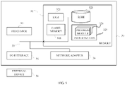
- FIG. 5 is a schematic structural diagram of an electronic device provided in embodiment 5 of the disclosure.
- the electronic device includes a processor and a memory configured to store computer programs executable by the processor.
- the computer programs when executed by the processor, are configured to perform the method for DCI design corresponding to embodiment 1 or 2.
- the electronic device 30 illustrated in FIG. 5 is merely an example, and should not impose any limitation on the function and the range of application of embodiments of the disclosure.
- the electronic device 30 may take the form of a general-purpose computing device.
- the electronic device 30 may be a server device.
- Components of the electronic device 30 may include, but are not limited to, at least one processor 31, at least one memory 32, and a bus 33 connecting different system components, including the memory 32 and the processor 31.
- the bus 33 includes a data bus, an address bus, and a control bus.
- the memory 32 may include a volatile memory, such as a random access memory (RAM) 321 and/or a cache memory 322, and may further include a read only memory (ROM) 323.
- RAM random access memory
- ROM read only memory
- the memory 32 may also include a program/utility 325 having a set of (at least one) program modules 324 including, but not limited to, an operating system, one or more applications, other program modules, and program data, each or some combination of these examples may include an implementation of a network environment.
- a program/utility 325 having a set of (at least one) program modules 324 including, but not limited to, an operating system, one or more applications, other program modules, and program data, each or some combination of these examples may include an implementation of a network environment.
- the processor 31 is configured to run a corresponding computer program stored in the memory 32 to execute various functional applications and data processing, such as the method for DCI design corresponding to embodiment 1 or 2 of the disclosure.
- the electronic device 30 may also communicate with one or more external devices 34, such as a keyboard, a pointing device, etc. Such communication may be performed through input/output (I/O) interface 35.
- the model-generated device 30 may also communicate with one or more networks (e.g., a local area network (LAN), a wide area network (WAN), and/or a public network such as an Internet) through a network adapter 36. As illustrated in FIG. 5 , the network adapter 36 communicates with other modules of the model-generated device 30 through the bus 33.
- networks e.g., a local area network (LAN), a wide area network (WAN), and/or a public network such as an Internet
- model-generated device 30 may be used in combination with other hardware and/or software modules, including but not limited to a microcode, a device driver, a redundant processor, an external disk drive array, a redundant array of independent disks (RAID) system, a tape drive, and a data backup storage system.
- a microcode e.g., a microcode, a device driver, a redundant processor, an external disk drive array, a redundant array of independent disks (RAID) system, a tape drive, and a data backup storage system.
- RAID redundant array of independent disks
- This embodiment provides a computer-readable storage medium storing computer programs which, when executed by a processor, are configured to perform operations of the method for DCI design of embodiment 1 or 2.
- the readable storage medium may include, but is not limited to, a portable disk, a hard disk, a RAM, a ROM, an erasable programmable ROM, an optical storage device, a magnetic storage device, or any suitable combination thereof.
- the disclosure can also be implemented in the form of a program product including program codes.
- the program codes are configured to cause the terminal device to perform operations of the method for DCI design of embodiment 1 or 2.
- the program codes for executing the disclosure can be written in any combination of one or more programming languages.
- the program codes can be completely executed on a UE, partially executed on a UE, executed as a separate software package, partially executed on a UE and partially executed on a remote device, or completely executed on a remote device.
Landscapes
- Engineering & Computer Science (AREA)
- Signal Processing (AREA)
- Computer Networks & Wireless Communication (AREA)
- Mobile Radio Communication Systems (AREA)
Abstract
Description
- This application claims priority to
Chinese Patent Application No. 202010093483.X, filed February 14, 2020 - The disclosure relates to the technical field of wireless communication, and in particular, to a method and a system for downlink control information (DCI) design, an electronic device, and a storage medium.
- At present, transmission configuration indicator (TCI) state information of a control channel is obtained according to a TCI state of a control resource set (CORESET) associated with the control channel. TCI state information of the CORESET is configured through radio resource control (RRC) or through the RRC and a medium access control (MAC) control element (CE). Specifically, when the CORESET is configured through the RRC, a list of candidate TCI states may be configured through the RRC. If only one TCI state is configured through the RRC, the MAC CE is not required for configuration. If more than one TCI state is configured through the RRC, the MAC CE is required for selection and configuration of a TCI state from these TCI states.
- However, in a related protocol, a configuration manner of the TCI state of the CORESET through the RRC or through the RRC and the MAC CE is likely to cause a problem of large delay and the like.
- A technical problem to be solved by the disclosure is to overcome a defect that a manner of configuring TCI state information of a control channel in related art is likely to cause a large delay, and a purpose of the disclosure is to provide a method and a system for DCI design, an electronic device, and a storage media.
- The disclosure solves the above-mentioned technical problem with the following technical solution.
- The disclosure provides a method for DCI design. The method includes: configuring TCI state information of a control channel through a DCI.
- Preferably, when the DCI is a common DCI, configuring the TCI state information of the control channel through the DCI includes: indicating TCI state information of each first CORESET corresponding to each information block in the common DCI dynamically, and/or indicating TCI state information of each first physical uplink control channel (PUCCH) resource corresponding to each information block in the common DCI dynamically, where each user equipment (UE) corresponds to one information block.
- Preferably, the method for design further includes: determining a first valid time corresponding to the configured TCI state information, where the first valid time is calculated according to a time slot in which a physical downlink control channel (PDCCH) is received and a predefined time sequence.
- Preferably, when the DCI is a dedicated DCI, configuring the TCI state information of the control channel through the DCI includes: indicating TCI state information of each second CORESET corresponding to the dedicated DCI dynamically, and/or indicating TCI state information of each second PUCCH resource corresponding to the dedicated DCI dynamically, where the dedicated DCI corresponds to one UE.
- Preferably, the method for design further includes: determining a second valid time corresponding to the configured TCI state information, where the second valid time is calculated according to a time slot in which a PDCCH is received and a predefined time sequence, or the second valid time is a time when the UE transmits a feedback signal to a network-side device.
- Preferably, the feedback signal transmitted by the UE to the network-side device includes hybrid automatic repeat request (HARQ)-acknowledgement (ACK) feedback information generated by the UE based on the received DCI.
- Preferably, after configuring the TCI state information of the control channel through the DCI, the method further includes: when configuration of the TCI state information of the control channel through a MAC CE is valid, determining that configuration or a configuration manner of the TCI state information of the control channel through the DCI is invalid, and determining the TCI state information configured through the MAC CE as the TCI state information of the control channel.
- The disclosure also provides a system for DCI design. The system for design includes an information configuration module. The information configuration module is configured to configure TCI state information of a control channel through a DCI.
- Preferably, when the DCI is a common DCI, the information configuration module is configured to: indicate TCI state information of each first CORESET corresponding to each information block in the common DCI dynamically, and/or indicate TCI state information of each first PUCCH resource corresponding to each information block in the common DCI dynamically, where each UE corresponds to one information block.
- Preferably, the system for design further includes a first determination module. The first determination module is configured to: determine a first valid time corresponding to the configured TCI state information, where the first valid time is calculated according to a time slot in which a PDCCH is received and a predefined time sequence.
- Preferably, when the DCI is a dedicated DCI, the information configuration module is configured to: indicate TCI state information of each second CORESET corresponding to the dedicated DCI dynamically, and/or indicate TCI state information of each second PUCCH resource corresponding to the dedicated DCI dynamically, where the dedicated DCI corresponds to one UE.
- Preferably, the system for design further includes a second determination module. The second determination module is configured to: determine a second valid time corresponding to the configured TCI state information, where the second valid time is calculated according to a time slot in which a PDCCH is received and a predefined time sequence, or the second valid time is a time when the UE transmits a feedback signal to a network-side device.
- Preferably, the feedback signal transmitted by the UE to the network-side device includes HARQ-ACK feedback information generated by the UE based on the received DCI.
- Preferably, the system for design further includes a third determination module. The third determination module is configured to: when configuration of the TCI state information of the control channel through a MAC CE is valid, determine that configuration or a configuration manner of the TCI state information of the control channel through the DCI is invalid, and determine the TCI state information configured through the MAC CE as the TCI state information of the control channel.
- The disclosure also provides an electronic device. The electronic device includes a processor and a memory configured to store computer programs executable by the processor. The computer programs, when executed by the processor, are configured to perform the method for DCI design described above.
- The disclosure also provides a computer-readable storage medium storing computer programs which, when executed by a processor, are configured to perform operations of the method for DCI design described above.
- The positive advantageous effect of the disclosure is as follow.
- In the disclosure, the TCI state information of the control channel is configured (indicated or updated) through the DCI, including a common DCI and/or a dedicated DCI, thereby solving a problem that a related protocol does not support indicating TCI state information of a CORESET and/or a PUCCH resource through a DCI, overcoming a problem of large delay of a related configuration manner, and improving efficiency, practicability, and effectiveness of configuration.
-
-
FIG. 1 is a flowchart of a method for DCI design according toembodiment 1 of the disclosure. -
FIG. 2 is a flowchart of a method for DCI design according toembodiment 2 of the disclosure. -
FIG. 3 is a schematic block diagram of a system for DCI design according toembodiment 3 of the disclosure. -
FIG. 4 is a schematic block diagram of a system for DCI design according toembodiment 4 of the disclosure. -
FIG. 5 is a schematic structural diagram of an electronic device for implementing a method for DCI design according to embodiment 5 of the disclosure. - The disclosure is further described below in embodiments, but the disclosure is not limited to the scope of described embodiments.
- A method for DCI design in this embodiment includes the following.
- S101. Configure TCI state information of a control channel through a DCI, which specifically includes indicating or updating the TCI state information of the control channel through the DCI.
- Specifically, as illustrated in
FIG. 1 , when the DCI is a common DCI, S101 includes the following. - S1011. Indicate TCI state information of each first CORESET corresponding to each information block in the common DCI dynamically, and/or indicate TCI state information of each first PUCCH resource corresponding to each information block in the common DCI dynamically, where each UE corresponds to one information block.
- S1012. Determine a first valid time corresponding to the configured TCI state information, where the first valid time is calculated according to a time slot in which a PDCCH is received and a predefined time sequence.
- S1013. When configuration of the TCI state information of the control channel through a MAC CE is valid, determine that configuration or a configuration manner of the TCI state information of the control channel through the DCI is invalid, and determine the TCI state information configured through the MAC CE as the TCI state information of the control channel.
- The following is a further explanation in combination with an actual configuration.
- Example 1: The DCI includes
block 1,block 2, ..., block i, where block i is for user j, i and j are natural numbers, and block i = [TCI for CORESET0, TCI for CORESET1, ...]. - The common DCI includes multiple information blocks, and each information block corresponds to a user and multiple CORESETs. Specifically, each information block contains TCI information in some or all of the CORESETs allocated to the user.
- The number of information blocks corresponding to the common DCI and the number of CORESETs corresponding to each information block are preset through network configuration, and can also be adjusted according to an actual situation.
- Example 2: The DCI includes
block 1,block 2, ..., block i, where block i is for user j, i and j are natural numbers, and block i = [TCI for PUCCH0, TCI for PUCCH1, ...]. - The common DCI includes multiple information blocks, and each information block corresponds to a user and multiple PUCCH resources or PUCCH resource groups. Specifically, each information block contains TCI information in some or all of the PUCCH resources/resource groups allocated to the user.
- The number of information blocks corresponding to the common DCI and the number of PUCCH resources/resource groups corresponding to each information block are preset through network configuration, and can also be adjusted according to an actual situation.
- The configured TCI state has a valid time t=n+k, where n represents the time slot of the PDCCH, and k represents the predefined time sequence, which is pre-configured by the network and can also be adjusted according to an actual situation.
- In addition, once the configuration of the TCI state information of the control channel through the MAC CE is valid, the configuration or the configuration manner of the TCI state information of the control channel through the DCI is invalid, and the TCI state information configured through the MAC CE is used as the TCI state information of the control channel.
- In this embodiment, the TCI state information of the control channel is configured through the common DCI, thereby solving a problem that a related protocol does not support indicating TCI state information of a CORESET and/or a PUCCH resource through a DCI, overcoming a problem of large delay of a related configuration manner, and improving efficiency, practicability, and effectiveness of configuration.
- A method for DCI design in this embodiment includes the following.
- S101. Configure TCI state information of a control channel through a DCI, which specifically includes indicating or updating the TCI state information of the control channel through the DCI.
- Specifically, as illustrated in
FIG. 2 , when the DCI is a dedicated DCI, S101 includes the following. - S1014. Indicate TCI state information of each second CORESET corresponding to the dedicated DCI dynamically, and/or indicate TCI state information of each second PUCCH resource corresponding to the dedicated DCI dynamically, where the dedicated DCI corresponds to a certain UE.
- S1015. Determine a second valid time corresponding to the configured TCI state information, where the second valid time is calculated according to a time slot in which a PDCCH is received and a predefined time sequence, or the second valid time is a time when the UE transmits a feedback signal to a network-side device.
- The feedback signal includes but is not limited to HARQ-ACK feedback information generated by the UE based on the received DCI.
- Optionally, regardless of the definition of the second valid time, there is a feedback signal, and an applicable scenario of the feedback signal is not limited in this embodiment.
- S1016. When configuration of the TCI state information of the control channel through a MAC CE is valid, determine that configuration or a configuration manner of the TCI state information of the control channel through the DCI is invalid, and determine the TCI state information configured through the MAC CE as the TCI state information of the control channel.
- The following is a further explanation in combination with an actual configuration.
- Example 1: The DCI includes TCI for CORESET 0, TCI for
CORESET 1, ...TCI for CORESET M. - The dedicated DCI corresponds to multiple CORESETs, the number of CORESETs allocated to the terminal is M+1, and M is a natural number.
- The number of CORESETs corresponding to the dedicated DCI is preset through network configuration, and can also be adjusted according to an actual situation.
- Example 2: The DCI includes TCI for PUCCH 0, TCI for
PUCCH 1, ... TCI for PUCCH N. - The dedicated DCI corresponds to multiple PUCCH resources or PUCCH resource groups, the number of PUCCH resources or PUCCH resource groups allocated to the terminal is N+1, and N is a natural number.
- The number of PUCCH resources or PUCCH resource groups corresponding to the dedicated DCI is preset through network configuration, and can also be adjusted according to an actual situation.
- The configured TCI state has a valid time t=n+k, where n represents the time slot of the PDCCH, and k represents the predefined time sequence, which is pre-configured by the network and can also be adjusted according to an actual situation, or the valid time t of the configured TCI state is a time when the UE transmits an ACK/NACK (a feedback signal) to a network-side device.
- In addition, once the configuration of the TCI state information of the control channel through the MAC CE is valid, the configuration or the configuration manner of the TCI state information of the control channel through the DCI is invalid, and the TCI state information configured through the MAC CE is used as the TCI state information of the control channel.
- In this embodiment, the TCI state information of the control channel is configured through the dedicated DCI, thereby solving a problem that a related protocol does not support indicating TCI state information of a CORESET and/or a PUCCH resource through a DCI, overcoming a problem of large delay of a related configuration manner, and improving efficiency, practicability, and effectiveness of configuration.
- As illustrated in
FIG. 3 , a system for DCI design in this embodiment includes aninformation configuration module 1, afirst determination module 2, and athird determination module 3. - The
information configuration module 1 is configured to configure TCI state information of a control channel through a DCI, which specifically includes indicating or updating the TCI state information of the control channel through the DCI. - Specifically, when the DCI is a common DCI, the
information configuration module 1 is configured to indicate TCI state information of each first CORESET corresponding to each information block in the common DCI dynamically, and/or indicate TCI state information of each first PUCCH resource corresponding to each information block in the common DCI dynamically, where each UE corresponds to one information block. - The
first determination module 2 is configured to determine a first valid time corresponding to the configured TCI state information, where the first valid time is calculated according to a time slot in which a PDCCH is received and a predefined time sequence. - The
third determination module 3 is configured to, when configuration of the TCI state information of the control channel through a MAC CE is valid, determine that configuration or a configuration manner of the TCI state information of the control channel through the DCI is invalid, and determine the TCI state information configured through the MAC CE as the TCI state information of the control channel. - The following is a further explanation in combination with an actual configuration.
- Example 1: The DCI includes
block 1,block 2, ..., block i, where block i is for user j, i and j are natural numbers, and block i = [TCI for CORESET0, TCI for CORESET1, ...]. - The common DCI includes multiple information blocks, and each information block corresponds to a user and multiple CORESETs. Specifically, each information block contains TCI information in some or all of the CORESETs allocated to the user.
- The number of information blocks corresponding to the common DCI and the number of CORESETs corresponding to each information block are preset through network configuration, and can also be adjusted according to an actual situation.
- Example 2: The DCI includes
block 1,block 2, ..., block i, where block i is for user j, i and j are natural numbers, and block i = [TCI for PUCCH0, TCI for PUCCH1, ...]. - The common DCI includes multiple information blocks, and each information block corresponds to a user and multiple PUCCH resources or PUCCH resource groups. Specifically, each information block contains TCI information in some or all of the PUCCH resources/resource groups allocated to the user.
- The number of information blocks corresponding to the common DCI and the number of PUCCH resources/resource groups corresponding to each information block are preset through network configuration, and can also be adjusted according to an actual situation.
- The configured TCI state has a valid time t=n+k, where n represents the time slot of the PDCCH, and k represents the predefined time sequence, which is pre-configured by the network and can also be adjusted according to an actual situation.
- In addition, once the configuration of the TCI state information of the control channel through the MAC CE is valid, the configuration or the configuration manner of the TCI state information of the control channel through the DCI is invalid, and the TCI state information configured through the MAC CE is used as the TCI state information of the control channel.
- In this embodiment, the TCI state information of the control channel is configured through the common DCI, thereby solving a problem that a related protocol does not support indicating TCI state information of a CORESET and/or a PUCCH resource through a DCI, overcoming a problem of large delay of a related configuration manner, and improving efficiency, practicability, and effectiveness of configuration.
- As illustrated in
FIG. 4 , a system for DCI design in this embodiment includes aninformation configuration module 1, asecond determination module 4, and athird determination module 3. - The
information configuration module 1 is configured to configure TCI state information of a control channel through a DCI, which specifically includes indicating or updating the TCI state information of the control channel through the DCI. - Specifically, when the DCI is a dedicated DCI, the
information configuration module 1 is configured to indicate TCI state information of each second CORESET corresponding to the dedicated DCI dynamically, and/or indicate TCI state information of each second PUCCH resource corresponding to the dedicated DCI dynamically, where the dedicated DCI corresponds to a certain UE. - The
second determination module 4 is configured to determine a second valid time corresponding to the configured TCI state information, where the second valid time is calculated according to a time slot in which a PDCCH is received and a predefined time sequence, or the second valid time is a time when the UE transmits a feedback signal to a network-side device. - The feedback signal includes but is not limited to HARQ-ACK feedback information generated by the UE based on the received DCI.
- Optionally, regardless of the definition of the second valid time, there is a feedback signal, and an applicable scenario of the feedback signal is not limited in this embodiment.
- The
third determination module 3 is configured to, when configuration of the TCI state information of the control channel through a MAC CE is valid, determine that configuration or a configuration manner of the TCI state information of the control channel through the DCI is invalid, and determine the TCI state information configured through the MAC CE as the TCI state information of the control channel. - The following is a further explanation in combination with an actual configuration.
- Example 1: The DCI includes TCI for CORESET 0, TCI for
CORESET 1, ...TCI for CORESET M. - The dedicated DCI corresponds to multiple CORESETs, the number of CORESETs allocated to the terminal is M+1, and M is a natural number.
- The number of CORESETs corresponding to the dedicated DCI is preset through network configuration, and can also be adjusted according to an actual situation.
- Example 2: The DCI includes TCI for PUCCH 0, TCI for
PUCCH 1, ... TCI for PUCCH N. - The dedicated DCI corresponds to multiple PUCCH resources or PUCCH resource groups, the number of PUCCH resources or PUCCH resource groups allocated to the terminal is N+1, and N is a natural number.
- The number of PUCCH resources or PUCCH resource groups corresponding to the dedicated DCI is preset through network configuration, and can also be adjusted according to an actual situation.
- The configured TCI state has a valid time t=n+k, where n represents the time slot of the PDCCH, and k represents the predefined time sequence, which is pre-configured by the network and can also be adjusted according to an actual situation, or the valid time t of the configured TCI state is a time when the UE transmits an ACK/NACK (a feedback signal) to a network-side device.
- In addition, once the configuration of the TCI state information of the control channel through the MAC CE is valid, the configuration or the configuration manner of the TCI state information of the control channel through the DCI is invalid, and the TCI state information configured through the MAC CE is used as the TCI state information of the control channel.
- In this embodiment, the TCI state information of the control channel is configured through the dedicated DCI, thereby solving a problem that a related protocol does not support indicating TCI state information of a CORESET and/or a PUCCH resource through a DCI, overcoming a problem of large delay of a related configuration manner, and improving efficiency, practicability, and effectiveness of configuration.
-
FIG. 5 is a schematic structural diagram of an electronic device provided in embodiment 5 of the disclosure. The electronic device includes a processor and a memory configured to store computer programs executable by the processor. The computer programs, when executed by the processor, are configured to perform the method for DCI design corresponding toembodiment electronic device 30 illustrated inFIG. 5 is merely an example, and should not impose any limitation on the function and the range of application of embodiments of the disclosure. - As illustrated in
FIG. 5 , theelectronic device 30 may take the form of a general-purpose computing device. For example, theelectronic device 30 may be a server device. Components of theelectronic device 30 may include, but are not limited to, at least oneprocessor 31, at least onememory 32, and abus 33 connecting different system components, including thememory 32 and theprocessor 31. - The
bus 33 includes a data bus, an address bus, and a control bus. - The
memory 32 may include a volatile memory, such as a random access memory (RAM) 321 and/or acache memory 322, and may further include a read only memory (ROM) 323. - The
memory 32 may also include a program/utility 325 having a set of (at least one)program modules 324 including, but not limited to, an operating system, one or more applications, other program modules, and program data, each or some combination of these examples may include an implementation of a network environment. - The
processor 31 is configured to run a corresponding computer program stored in thememory 32 to execute various functional applications and data processing, such as the method for DCI design corresponding toembodiment - The
electronic device 30 may also communicate with one or moreexternal devices 34, such as a keyboard, a pointing device, etc. Such communication may be performed through input/output (I/O)interface 35. Also, the model-generateddevice 30 may also communicate with one or more networks (e.g., a local area network (LAN), a wide area network (WAN), and/or a public network such as an Internet) through anetwork adapter 36. As illustrated inFIG. 5 , thenetwork adapter 36 communicates with other modules of the model-generateddevice 30 through thebus 33. It should be understood that, although not illustrated, the model-generateddevice 30 may be used in combination with other hardware and/or software modules, including but not limited to a microcode, a device driver, a redundant processor, an external disk drive array, a redundant array of independent disks (RAID) system, a tape drive, and a data backup storage system. - It should be noted that, although several units/modules or sub-units/sub-modules of the electronic device are mentioned above, such division is merely exemplary but not mandatory. Actually, features and functions of two or more units/modules described above may be embodied in one unit/module according to embodiments of the disclosure. Conversely, features and functions of one unit/module described above may be further subdivided to be embodied in multiple units/modules.
- This embodiment provides a computer-readable storage medium storing computer programs which, when executed by a processor, are configured to perform operations of the method for DCI design of
embodiment - The readable storage medium may include, but is not limited to, a portable disk, a hard disk, a RAM, a ROM, an erasable programmable ROM, an optical storage device, a magnetic storage device, or any suitable combination thereof.
- In possible implementations, the disclosure can also be implemented in the form of a program product including program codes. When the program product runs on a terminal device, the program codes are configured to cause the terminal device to perform operations of the method for DCI design of
embodiment - The program codes for executing the disclosure can be written in any combination of one or more programming languages. The program codes can be completely executed on a UE, partially executed on a UE, executed as a separate software package, partially executed on a UE and partially executed on a remote device, or completely executed on a remote device.
- Although specific implementations of the disclosure are described above, those skilled in the art should understand that, this is only an illustration, and the protection scope of the disclosure is defined by the appended claims. Those skilled in the art can make various changes or modifications to these implementations without departing from the principle and essence of the disclosure, but all of these changes and modifications shall fall within the protection scope of the disclosure.
Claims (16)
- A method for downlink control information (DCI) design, comprising:
configuring transmission configuration indicator (TCI) state information of a control channel through a DCI. - The method of claim 1, wherein when the DCI is a common DCI, configuring the TCI state information of the control channel through the DCI comprises:indicating TCI state information of each first control resource set (CORESET) corresponding to each information block in the common DCI dynamically; and/orindicating TCI state information of each first physical uplink control channel (PUCCH) resource corresponding to each information block in the common DCI dynamically, whereineach user equipment (UE) corresponds to one information block.
- The method of claim 2, further comprising:
determining a first valid time corresponding to the configured TCI state information, wherein the first valid time is calculated according to a time slot in which a physical downlink control channel (PDCCH) is received and a predefined time sequence. - The method of claim 1, wherein when the DCI is a dedicated DCI, configuring the TCI state information of the control channel through the DCI comprises:indicating TCI state information of each second CORESET corresponding to the dedicated DCI dynamically; and/orindicating TCI state information of each second PUCCH resource corresponding to the dedicated DCI dynamically, whereinthe dedicated DCI corresponds to one UE.
- The method of claim 4, further comprising:
determining a second valid time corresponding to the configured TCI state information, wherein the second valid time is calculated according to a time slot in which a PDCCH is received and a predefined time sequence, or the second valid time is a time when the UE transmits a feedback signal to a network-side device. - The method of claim 5, wherein the feedback signal transmitted by the UE to the network-side device comprises hybrid automatic repeat request (HARQ)-acknowledgement (ACK) feedback information generated by the UE based on the received DCI.
- The method of at least one of claims 3 and 5, wherein after configuring the TCI state information of the control channel through the DCI, the method further comprises:
when configuration of the TCI state information of the control channel through a medium access control (MAC) control element (CE) is valid,determining that configuration or a configuration manner of the TCI state information of the control channel through the DCI is invalid; anddetermining the TCI state information configured through the MAC CE as the TCI state information of the control channel. - A system for downlink control information (DCI) design, comprising:
an information configuration module configured to configure transmission configuration indicator (TCI) state information of a control channel through a DCI. - The system of claim 8, wherein when the DCI is a common DCI, the information configuration module is configured to:indicate TCI state information of each first control resource set (CORESET) corresponding to each information block in the common DCI dynamically; and/orindicate TCI state information of each first physical uplink control channel (PUCCH) resource corresponding to each information block in the common DCI dynamically, whereineach user equipment (UE) corresponds to one information block.
- The system of claim 9, further comprising a first determination module configured to:
determine a first valid time corresponding to the configured TCI state information, wherein the first valid time is calculated according to a time slot in which a physical downlink control channel (PDCCH) is received and a predefined time sequence. - The system of claim 8, wherein when the DCI is a dedicated DCI, the information configuration module is configured to:indicate TCI state information of each second CORESET corresponding to the dedicated DCI dynamically; and/orindicate TCI state information of each second PUCCH resource corresponding to the dedicated DCI dynamically, whereinthe dedicated DCI corresponds to one UE.
- The system of claim 11, further comprising a second determination module configured to:
determine a second valid time corresponding to the configured TCI state information, wherein the second valid time is calculated according to a time slot in which a PDCCH is received and a predefined time sequence, or the second valid time is a time when the UE transmits a feedback signal to a network-side device. - The system of claim 12, wherein the feedback signal transmitted by the UE to the network-side device comprises hybrid automatic repeat request (HARQ)-acknowledgement (ACK) feedback information generated by the UE based on the received DCI.
- The system of at least one of claims 9 and 11, further comprising a third determination module configured to:
when configuration of the TCI state information of the control channel through a medium access control (MAC) control element (CE) is valid,determine that configuration or a configuration manner of the TCI state information of the control channel through the DCI is invalid; anddetermine the TCI state information configured through the MAC CE as the TCI state information of the control channel. - An electronic device, comprising:a processor; anda memory configured to store computer programs executable by the processor, wherein the computer programs, when executed by the processor, are configured to perform the method of any of claims 1 to 7.
- A computer-readable storage medium storing computer programs which, when executed by a processor, are configured to perform the method of any of claims 1 to 7.
Applications Claiming Priority (2)
| Application Number | Priority Date | Filing Date | Title |
|---|---|---|---|
| CN202010093483.XA CN111315021B (en) | 2020-02-14 | 2020-02-14 | Design method, system, electronic device and storage medium of downlink control information |
| PCT/CN2021/075652 WO2021160048A1 (en) | 2020-02-14 | 2021-02-05 | Downlink control information design method and system, electronic device and storage medium |
Publications (2)
| Publication Number | Publication Date |
|---|---|
| EP4106451A1 true EP4106451A1 (en) | 2022-12-21 |
| EP4106451A4 EP4106451A4 (en) | 2024-07-10 |
Family
ID=71147120
Family Applications (1)
| Application Number | Title | Priority Date | Filing Date |
|---|---|---|---|
| EP21753015.3A Pending EP4106451A4 (en) | 2020-02-14 | 2021-02-05 | METHOD AND SYSTEM FOR DESIGNING DOWNLINK CONTROL INFORMATION, ELECTRONIC DEVICE AND STORAGE MEDIUM |
Country Status (4)
| Country | Link |
|---|---|
| US (1) | US12470345B2 (en) |
| EP (1) | EP4106451A4 (en) |
| CN (1) | CN111315021B (en) |
| WO (1) | WO2021160048A1 (en) |
Families Citing this family (3)
| Publication number | Priority date | Publication date | Assignee | Title |
|---|---|---|---|---|
| CN111315021B (en) * | 2020-02-14 | 2023-02-17 | 北京紫光展锐通信技术有限公司 | Design method, system, electronic device and storage medium of downlink control information |
| CN113472408B (en) * | 2020-03-31 | 2022-09-02 | 北京紫光展锐通信技术有限公司 | Information transmitting and receiving method and device, storage medium and terminal |
| KR20240022614A (en) * | 2021-06-18 | 2024-02-20 | 베이징 시아오미 모바일 소프트웨어 컴퍼니 리미티드 | Information indication methods, devices, user equipment, base stations and storage media |
Family Cites Families (11)
| Publication number | Priority date | Publication date | Assignee | Title |
|---|---|---|---|---|
| JP6845883B2 (en) * | 2018-03-26 | 2021-03-24 | 華碩電腦股▲ふん▼有限公司 | Methods and devices for buffering downlink data in consideration of cross-carrier scheduling in wireless communication systems. |
| CN110351052B (en) * | 2018-04-04 | 2020-08-28 | 维沃移动通信有限公司 | Channel and signal transmission method and communication equipment |
| CN110661594B (en) * | 2018-06-29 | 2022-04-05 | 华为技术有限公司 | Multiplexing method and equipment for channel state information and hybrid automatic repeat request acknowledgement |
| US11095415B2 (en) * | 2018-07-02 | 2021-08-17 | Samsung Electronics Co., Ltd. | Enhancements to reception reliability for data and control information |
| EP3591856B1 (en) * | 2018-07-04 | 2021-10-27 | Intel Corporation | Techniques for control of beam switching |
| EP3826417B1 (en) * | 2018-07-25 | 2024-04-17 | Beijing Xiaomi Mobile Software Co., Ltd. | Transmission configuration method and device |
| US11968679B2 (en) * | 2019-01-09 | 2024-04-23 | Comcast Cable Communications, Llc | Methods, systems, and apparatuses for beam management |
| CN110535571A (en) * | 2019-03-28 | 2019-12-03 | 中兴通讯股份有限公司 | Information transmission method and device and information determination method and device |
| US11497021B2 (en) * | 2019-11-04 | 2022-11-08 | Samsung Electronics Co., Ltd. | Method and apparatus for fast beam management |
| US11349553B2 (en) * | 2019-11-15 | 2022-05-31 | Qualcomm Incorporated | Transmission configuration indication field invalidation after PDSCH beam setting |
| CN111315021B (en) * | 2020-02-14 | 2023-02-17 | 北京紫光展锐通信技术有限公司 | Design method, system, electronic device and storage medium of downlink control information |
-
2020
- 2020-02-14 CN CN202010093483.XA patent/CN111315021B/en active Active
-
2021
- 2021-02-05 US US17/799,035 patent/US12470345B2/en active Active
- 2021-02-05 WO PCT/CN2021/075652 patent/WO2021160048A1/en not_active Ceased
- 2021-02-05 EP EP21753015.3A patent/EP4106451A4/en active Pending
Also Published As
| Publication number | Publication date |
|---|---|
| WO2021160048A1 (en) | 2021-08-19 |
| US20230081467A1 (en) | 2023-03-16 |
| CN111315021A (en) | 2020-06-19 |
| US12470345B2 (en) | 2025-11-11 |
| EP4106451A4 (en) | 2024-07-10 |
| CN111315021B (en) | 2023-02-17 |
Similar Documents
| Publication | Publication Date | Title |
|---|---|---|
| CN110034892B (en) | HARQ-ACK feedback time determination method, indication method, terminal device and network device | |
| US11910393B2 (en) | Uplink control information sending, uplink control information receiving method, and apparatus | |
| US20230058830A1 (en) | Method for configuring srs resource, base station, and storage medium | |
| US12470345B2 (en) | Method for downlink control information design, electronic device, and storage medium | |
| WO2019184943A1 (en) | Data transmission method, terminal device, and network device | |
| EP3780445A1 (en) | Data transmission method, terminal device, and network device | |
| JP7073525B2 (en) | Physical uplink control channel resource determination method and communication device | |
| JP2015527676A (en) | Method and apparatus for patching | |
| CN114258135A (en) | Uplink channel transmission method, device and terminal | |
| US20150277782A1 (en) | Cache Driver Management of Hot Data | |
| CN117044144A (en) | HARQ-ACK codebook processing | |
| US20200034042A1 (en) | Method for writing data in a distributed storage system | |
| KR20200019860A (en) | Data Instruction Methods and Related Products | |
| US9189406B2 (en) | Placement of data in shards on a storage device | |
| CN111262654A (en) | Method, system, electronic device and medium for responding to aperiodic CSI request | |
| WO2019137479A1 (en) | Method for determining number of transmission resources for channel state information, and terminal device | |
| KR20200090259A (en) | Data transmission method, device, computer device and storage medium | |
| US11785603B2 (en) | Method, apparatus and non-transitory computer readable medium for selecting a PUSCH to carry UCI | |
| JP2025515171A (en) | Method, device and terminal for determining hybrid automatic repeat request-acknowledgement HARQ-ACK codebook | |
| CN111586841B (en) | Terminal paging optimization method, system, device and readable storage medium | |
| CN115242807B (en) | Data access method in 5G communication system and related equipment | |
| US10254961B2 (en) | Dynamic load based memory tag management | |
| CN110034860B (en) | Method, terminal equipment and network equipment for transmitting HARQ-ACK | |
| CN110868696A (en) | Selective analysis method, device and equipment for Internet of vehicles data and storage medium | |
| CN117479338A (en) | Access control methods, systems, equipment, media, chips, terminals and base stations |
Legal Events
| Date | Code | Title | Description |
|---|---|---|---|
| STAA | Information on the status of an ep patent application or granted ep patent |
Free format text: STATUS: THE INTERNATIONAL PUBLICATION HAS BEEN MADE |
|
| PUAI | Public reference made under article 153(3) epc to a published international application that has entered the european phase |
Free format text: ORIGINAL CODE: 0009012 |
|
| STAA | Information on the status of an ep patent application or granted ep patent |
Free format text: STATUS: REQUEST FOR EXAMINATION WAS MADE |
|
| 17P | Request for examination filed |
Effective date: 20220914 |
|
| AK | Designated contracting states |
Kind code of ref document: A1 Designated state(s): AL AT BE BG CH CY CZ DE DK EE ES FI FR GB GR HR HU IE IS IT LI LT LU LV MC MK MT NL NO PL PT RO RS SE SI SK SM TR |
|
| DAV | Request for validation of the european patent (deleted) | ||
| DAX | Request for extension of the european patent (deleted) | ||
| RIC1 | Information provided on ipc code assigned before grant |
Ipc: H04L 1/1812 20230101ALI20240219BHEP Ipc: H04W 72/04 20090101AFI20240219BHEP |
|
| A4 | Supplementary search report drawn up and despatched |
Effective date: 20240610 |
|
| RIC1 | Information provided on ipc code assigned before grant |
Ipc: H04L 1/1812 20230101ALI20240604BHEP Ipc: H04W 72/04 20090101AFI20240604BHEP |