EP4106303A1 - Mobile communication device, mobile communication base station, and mobile communication method - Google Patents
Mobile communication device, mobile communication base station, and mobile communication method Download PDFInfo
- Publication number
- EP4106303A1 EP4106303A1 EP21770442.8A EP21770442A EP4106303A1 EP 4106303 A1 EP4106303 A1 EP 4106303A1 EP 21770442 A EP21770442 A EP 21770442A EP 4106303 A1 EP4106303 A1 EP 4106303A1
- Authority
- EP
- European Patent Office
- Prior art keywords
- wireless communication
- communication device
- transmission
- unit
- storage
- Prior art date
- Legal status (The legal status is an assumption and is not a legal conclusion. Google has not performed a legal analysis and makes no representation as to the accuracy of the status listed.)
- Granted
Links
Images













Classifications
-
- H—ELECTRICITY
- H04—ELECTRIC COMMUNICATION TECHNIQUE
- H04L—TRANSMISSION OF DIGITAL INFORMATION, e.g. TELEGRAPHIC COMMUNICATION
- H04L1/00—Arrangements for detecting or preventing errors in the information received
- H04L1/12—Arrangements for detecting or preventing errors in the information received by using return channel
- H04L1/16—Arrangements for detecting or preventing errors in the information received by using return channel in which the return channel carries supervisory signals, e.g. repetition request signals
- H04L1/18—Automatic repetition systems, e.g. Van Duuren systems
- H04L1/1803—Stop-and-wait protocols
-
- H—ELECTRICITY
- H04—ELECTRIC COMMUNICATION TECHNIQUE
- H04M—TELEPHONIC COMMUNICATION
- H04M1/00—Substation equipment, e.g. for use by subscribers
- H04M1/72—Mobile telephones; Cordless telephones, i.e. devices for establishing wireless links to base stations without route selection
- H04M1/724—User interfaces specially adapted for cordless or mobile telephones
- H04M1/72448—User interfaces specially adapted for cordless or mobile telephones with means for adapting the functionality of the device according to specific conditions
- H04M1/72454—User interfaces specially adapted for cordless or mobile telephones with means for adapting the functionality of the device according to specific conditions according to context-related or environment-related conditions
-
- H—ELECTRICITY
- H04—ELECTRIC COMMUNICATION TECHNIQUE
- H04L—TRANSMISSION OF DIGITAL INFORMATION, e.g. TELEGRAPHIC COMMUNICATION
- H04L1/00—Arrangements for detecting or preventing errors in the information received
- H04L1/0001—Systems modifying transmission characteristics according to link quality, e.g. power backoff
- H04L1/0006—Systems modifying transmission characteristics according to link quality, e.g. power backoff by adapting the transmission format
- H04L1/0007—Systems modifying transmission characteristics according to link quality, e.g. power backoff by adapting the transmission format by modifying the frame length
-
- H—ELECTRICITY
- H04—ELECTRIC COMMUNICATION TECHNIQUE
- H04L—TRANSMISSION OF DIGITAL INFORMATION, e.g. TELEGRAPHIC COMMUNICATION
- H04L1/00—Arrangements for detecting or preventing errors in the information received
- H04L1/0001—Systems modifying transmission characteristics according to link quality, e.g. power backoff
- H04L1/0014—Systems modifying transmission characteristics according to link quality, e.g. power backoff by adapting the source coding
-
- H—ELECTRICITY
- H04—ELECTRIC COMMUNICATION TECHNIQUE
- H04L—TRANSMISSION OF DIGITAL INFORMATION, e.g. TELEGRAPHIC COMMUNICATION
- H04L1/00—Arrangements for detecting or preventing errors in the information received
- H04L1/20—Arrangements for detecting or preventing errors in the information received using signal quality detector
- H04L1/203—Details of error rate determination, e.g. BER, FER or WER
-
- H—ELECTRICITY
- H04—ELECTRIC COMMUNICATION TECHNIQUE
- H04L—TRANSMISSION OF DIGITAL INFORMATION, e.g. TELEGRAPHIC COMMUNICATION
- H04L65/00—Network arrangements, protocols or services for supporting real-time applications in data packet communication
- H04L65/40—Support for services or applications
- H04L65/4061—Push-to services, e.g. push-to-talk or push-to-video
-
- H—ELECTRICITY
- H04—ELECTRIC COMMUNICATION TECHNIQUE
- H04L—TRANSMISSION OF DIGITAL INFORMATION, e.g. TELEGRAPHIC COMMUNICATION
- H04L65/00—Network arrangements, protocols or services for supporting real-time applications in data packet communication
- H04L65/80—Responding to QoS
-
- H—ELECTRICITY
- H04—ELECTRIC COMMUNICATION TECHNIQUE
- H04M—TELEPHONIC COMMUNICATION
- H04M3/00—Automatic or semi-automatic exchanges
- H04M3/22—Arrangements for supervision, monitoring or testing
- H04M3/2236—Quality of speech transmission monitoring
-
- H—ELECTRICITY
- H04—ELECTRIC COMMUNICATION TECHNIQUE
- H04M—TELEPHONIC COMMUNICATION
- H04M3/00—Automatic or semi-automatic exchanges
- H04M3/42—Systems providing special services or facilities to subscribers
- H04M3/56—Arrangements for connecting several subscribers to a common circuit, i.e. affording conference facilities
- H04M3/568—Arrangements for connecting several subscribers to a common circuit, i.e. affording conference facilities audio processing specific to telephonic conferencing, e.g. spatial distribution, mixing of participants
-
- H—ELECTRICITY
- H04—ELECTRIC COMMUNICATION TECHNIQUE
- H04W—WIRELESS COMMUNICATION NETWORKS
- H04W4/00—Services specially adapted for wireless communication networks; Facilities therefor
- H04W4/06—Selective distribution of broadcast services, e.g. multimedia broadcast multicast service [MBMS]; Services to user groups; One-way selective calling services
- H04W4/10—Push-to-Talk [PTT] or Push-On-Call services
-
- H—ELECTRICITY
- H04—ELECTRIC COMMUNICATION TECHNIQUE
- H04W—WIRELESS COMMUNICATION NETWORKS
- H04W4/00—Services specially adapted for wireless communication networks; Facilities therefor
- H04W4/02—Services making use of location information
-
- Y—GENERAL TAGGING OF NEW TECHNOLOGICAL DEVELOPMENTS; GENERAL TAGGING OF CROSS-SECTIONAL TECHNOLOGIES SPANNING OVER SEVERAL SECTIONS OF THE IPC; TECHNICAL SUBJECTS COVERED BY FORMER USPC CROSS-REFERENCE ART COLLECTIONS [XRACs] AND DIGESTS
- Y02—TECHNOLOGIES OR APPLICATIONS FOR MITIGATION OR ADAPTATION AGAINST CLIMATE CHANGE
- Y02D—CLIMATE CHANGE MITIGATION TECHNOLOGIES IN INFORMATION AND COMMUNICATION TECHNOLOGIES [ICT], I.E. INFORMATION AND COMMUNICATION TECHNOLOGIES AIMING AT THE REDUCTION OF THEIR OWN ENERGY USE
- Y02D30/00—Reducing energy consumption in communication networks
- Y02D30/70—Reducing energy consumption in communication networks in wireless communication networks
Definitions
- the present invention relates to a wireless communication device, a wireless communication base station, and a wireless communication method.
- Patent Literature 1 In a case in which a wireless communication terminal cannot perform transmission in a wireless communication system, there is known a technique of stopping normal transmission, recording transmission content in a memory, and then, when transmission is enabled thereafter, reproducing the transmission content recorded in the memory at high speed until the recorded transmission content catches up current transmission content to enable a smooth conversation without a lack of transmission content (for example, Patent Literature 1).
- Patent Literature 1 Japanese Patent No. 3066311 Summary
- a wireless communication base station monitors transmission signal strength from a wireless communication terminal, determines whether the wireless communication terminal is present within a service area thereof, and when the wireless communication terminal is out of the service area of the wireless communication base station, a wireless line control station transmits a transmission disabled signal to the wireless communication terminal via the wireless communication base station. That is, the technique disclosed in Patent Literature 1 has been developed assuming duplex communication (bidirectional communication) by which a radio wave condition can be monitored even during transmission.
- Patent Literature 1 in a case in which a transmission disabled period from when transmission is disabled until transmission is enabled is prolonged, and a temporal delay caused in the transmission disabled period cannot be eliminated, the transmission content recorded in the memory needs to be cleared, that is, the transmission content in the transmission disabled period needs to be discarded.
- the present disclosure provides a wireless communication device that can transmit transmission content quickly as much as possible, a wireless communication base station that relays the transmission content, and a wireless communication method that can transmit the transmission content quickly as much as possible when a favorable communication environment cannot be obtained.
- a wireless communication device comprising: a communication unit configured to transmit/receive signals to/from another wireless communication device using a channel frequency; a storage configured to store at least voice data collected by a microphone; an operation unit configured to detect a transmission starting operation and a transmission stopping operation; a communication quality measuring unit configured to measure a bit error rate indicating quality of communication using the channel frequency for each predetermined period; and a controller configured to control at least the communication unit and the storage in accordance with the transmission starting operation and the transmission stopping operation, wherein the controller is further configured to; control the storage to store, in a case in which the operation unit detects the transmission starting operation when the channel frequency is used by other wireless communication devices, the voice data until the operation unit detects the transmission stopping operation, control the communication unit to transmit, in a case in which the bit error rate measured by the communication quality measuring unit is smaller than a first threshold when the channel frequency is not used by other wireless communication devices, all pieces of voice data that have not been transmitted of the voice data stored in the storage, and control the
- a wireless communication base station configured to relay communication among multiple wireless communication devices, the wireless communication base station comprising: a communication unit configured to transmit/receive signals to/from the wireless communication devices; a storage in which at least a transmission enabled range of the wireless communication base station is stored; a determination unit configured to determine whether each of the wireless communication devices is present within the transmission enabled range based on positional information of each of the wireless communication devices received by the communication unit; and a controller configured to control at least the communication unit and the storage in accordance with a determination result obtained by the determination unit, wherein the controller is further configured to; perform control, in a case in which the wireless communication base station relays voice data that is transmitted from one wireless communication device to another wireless communication device of the wireless communication devices and the voice data transmitted from the one communication device is divided into multiple pieces of divided data, to successively combine the multiple pieces of divided data on a time-series basis, and to restore the voice data transmitted from the one wireless communication device to be stored in the storage, and control the communication unit, in a case
- a wireless communication method comprising: storing voice data in a wireless communication device until a transmission stopping operation is detected after a transmission starting operation is detected when a channel frequency used for communication is used by other wireless communication devices; measuring a bit error rate indicating quality of communication using the channel frequency for each predetermined period; transmitting, in a case in which the bit error rate is smaller than a first threshold when the channel frequency is not used by other wireless communication devices, all pieces of voice data that have not been transmitted of the stored voice data; and transmitting, in a case in which the bit error rate is equal to or larger than the first threshold and smaller than a second thresholda when the channel frequency is not used by other wireless communication devices, pieces of divided data having a predetermined length from a head of the voice data that has not been transmitted of the stored voice data.
- FIG. 1 is a conceptual diagram for explaining the configuration of the wireless communication system according to the first embodiment of the present disclosure.
- a wireless communication system 1 includes, for example, a wireless communication device 10a, a wireless communication device 10b, a wireless communication device 10c, a wireless communication device 10d, and a wireless communication device 10e.
- a wireless communication device 10a belongs to the same group.
- a wireless communication device 10b belongs to the same group.
- a wireless communication device 10c belongs to the same group.
- a wireless communication device 10d belongs to the same group.
- a wireless communication device 10e belongs to the same group.
- the wireless communication device 10a to the wireless communication device 10e perform group communication with each other by unidirectional communication of a Push to Talk (PTT) type.
- FIG. 1 illustrates an example in which the wireless communication device 10a to the wireless communication device 10e that perform group communication are present within a transmission enabled range R of a wireless communication base station 2.
- the transmission enabled range R of the wireless communication base station 2 indicates a range in which a predetermined radio wave intensity required for performing stable transmission/reception between the respective wireless communication devices can be obtained.
- the wireless communication device 10a to the wireless communication device 10e perform group communication while appropriately switching between multiple call channels (channel frequencies).
- the call channels (channel frequencies) used for performing group communication by the wireless communication device 10a to the wireless communication device 10e are shared with another group that is different from the group to which the wireless communication device 10a to the wireless communication device 10e belong.
- the wireless communication device 10a to the wireless communication device 10e may be collectively referred to as a wireless communication device 10.
- the number of the wireless communication devices 10 belonging to the same group is not limited.
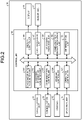
- FIG. 2 is a block diagram illustrating an example of the configuration of the wireless communication device according to the first embodiment of the present disclosure.
- the wireless communication device 10 includes a GPS reception unit 11, a communication unit 12, a storage 13, an operation unit 14, a display 15, a controller 16, and a microphone 17.
- the wireless communication device 10 illustrated in FIG. 2 is a wireless communication device having a group communication function by unidirectional communication of PTT type.
- the GPS reception unit 11 is constituted of a GPS reception circuit, a GPS reception antenna, and the like, and receives GPS signals.
- the GPS reception unit 11 outputs the received GPS signals to a positional information acquisition unit (a position measuring unit) 162.
- the communication unit 12 performs wireless communication with another wireless communication device by unidirectional communication of PTT type via the wireless communication base station 2. Specifically, the communication unit 12 transmits various pieces of information to the other wireless communication device, and receives various pieces of information from the other wireless communication device. Specifically, the various pieces of information are various kinds of data including voice data, still image data, video data, and document data. In the present disclosure, the voice data may include myltiple pieces of divided data that are divided on a time-series basis.
- a type of data to be transmitted/received to/from the other wireless communication device by the communication unit 12 is not particularly limited.
- the communication unit 12 may have a function of performing short-range wireless communication, or may have a function of performing long-range wireless communication.
- the communication unit 12 may perform wireless communication with the other wireless communication device without using the wireless communication base station 2.
- the communication unit 12 may be constituted of a communication circuit and the like.
- the storage 13 stores various pieces of information.
- the storage 13 stores group information about the group to which the wireless communication device 10 belongs.
- the group information may include positional information or identification information such as an identification ID of the other wireless communication device belonging to the group, the call channels (channel frequencies) used for the group communication, and the like.
- the storage 13 stores voice data collected by the microphone 17. Additionally, in the present disclosure, the storage 13 stores thresholds (a first threshold and a second threshold) for a bit error rate (hereinafter, referred to as a "BER") indicating a communication quality index of the communication unit 12.
- the storage 13 can be implemented by a semiconductor memory element such as a random access memory (RAM) and a flash memory, or a storage device such as a hard disk and a solid state drive.
- the operation unit 14 receives various operations for the controller 16.
- the various operations include, for example, an operation of switching between ON and OFF of a transmission function (a transmission starting operation and a transmission stopping operation in the present disclosure), and an operation of switching between a data transmission state and a data reception state.
- the operation unit 14 outputs, to an operation controller 165, an operation signal corresponding to a received operation.
- the operation unit 14 can implement reception of a user's operation by a physical switch or a touch panel disposed on the display 15.
- the display 15 displays various images constituting a user interface.
- the display 15 displays information for starting or stopping transmission.
- the display 15 is, for example, a display including a liquid crystal display (LCD), an organic Electro-Luminescence (EL) display, or the like.
- the display 15 may include, for example, a light emitting unit such as a light emitting diode (LED).
- the controller 16 is implemented when a computer program stored in the storage (for example, a computer program according to the present disclosure, not illustrated) is executed by a central processing unit (CPU), a micro processing unit (MPU), or the like using a RAM or the like as a working area.
- the controller 16 is a controller which may be implemented by an integrated circuit such as an application specific integrated circuit (ASIC) or a field programmable gate array (FPGA), for example.
- ASIC application specific integrated circuit
- FPGA field programmable gate array
- the microphone 17 converts, for example, voice input by utterance and the like into a voice signal.
- the controller 16 includes a device information acquisition unit 161, the positional information acquisition unit 162, a communication controller 163, a storage controller 164, the operation controller 165, a display controller 166, a voice processing unit 167, a voice data switching unit 168, a communication quality measuring unit 169, and a determination unit 170.
- the device information acquisition unit 161 acquires various pieces of information about the other wireless communication device. For example, the device information acquisition unit 161 acquires identification information such as an identification ID, positional information, and the like of the other wireless communication device received by the communication unit 12. The information acquired by the device information acquisition unit 161 is not limited thereto.
- the positional information acquisition unit 162 acquires current positional information of the wireless communication device 10.
- the positional information acquisition unit 162 acquires, for example, the current positional information of the wireless communication device 10 based on GPS signals received by the GPS reception unit 11.
- the communication controller 163 controls communication between the wireless communication device 10 and the other wireless communication device 10 belonging to the same group of the wireless communication device 10 by controlling the communication unit 12.
- the communication controller 163 transmits/receives various kinds of data to/from the other wireless communication device 10 by controlling the communication unit 12, for example.
- the communication controller 163 transmits/receives, for example, voice data collected by the microphone 17 or voice data stored in the storage 13 to/from the other wireless communication device 10 by controlling the communication unit 12.
- the storage controller 164 stores various pieces of information in the storage 13. For example, the storage controller 164 stores, in the storage 13, positional information and identification information such as an identification ID of the other wireless communication device acquired by the device information acquisition unit 161, a channel frequency that is currently used by the group, and the like. In the present disclosure, for example, the storage controller 164 stores voice data collected by the microphone 17 in the storage 13. The storage controller 164 stores, for example, the positional information of the wireless communication device 10 in the storage 13.
- the storage controller 164 reads out various pieces of information from the storage 13. For example, the storage controller 164 reads out the identification information such as the identification ID, the positional information, and the like of the other wireless communication device stored in the storage 13. In the present disclosure, the storage controller 164 reads out the voice data stored in the storage 13, for example. For example, the storage controller 164 reads out the positional information of the wireless communication device 10 stored in the storage 13.
- the display controller 166 causes the display 15 to display various images.
- the display controller 166 causes the display 15 to display various images constituting the user interface, for example.
- the display controller 166 causes the display 15 to display information for starting or stopping transmission.
- the voice processing unit 167 processes (for example, digitally converts or encrypts) the voice signal collected by the microphone 17, to be output to the voice data switching unit 168 as voice data for transmission.
- the voice data switching unit 168 performs a switching process for the voice data. Specifically, the voice data switching unit 168 switches an output destination of the voice data collected by the microphone 17 and processed by the voice processing unit 167, between the communication unit 12 and the storage 13. Additionally, the voice data switching unit 168 switches an output source of the voice data to the communication unit 12 between the voice processing unit 167 and the storage 13.
- the communication quality measuring unit 169 measures communication quality of the communication unit 12. Specifically, the communication quality measuring unit 169 measures the BER as the communication quality index of the communication unit 12, for example. A method of measuring the BER by the communication quality measuring unit 169 is not particularly limited.
- the determination unit 170 performs various kinds of determination processes in the wireless communication device 10. Specific examples of the determination processes performed by the determination unit 170 will be described later in detail in a process of determining whether real-time data transmission can be performed, a process of determining whether voice recording data transmission can be performed, a voice recording data transmission process, and a voice recording data relay process.
- FIG. 3 is a block diagram illustrating an example of the configuration of the wireless communication base station according to the first embodiment of the present disclosure.
- the wireless communication base station 2 includes a communication unit 22, a storage 23, and a controller 26.
- the wireless communication base station 2 illustrated in FIG. 3 is a wireless communication base station having a function of relaying unidirectional communication among the wireless communication devices that perform group communication by unidirectional communication of PTT type.
- the wireless communication devices that perform group communication by unidirectional communication of PTT type are also referred to as "wireless communication devices in the group”.
- the wireless communication base station 2 relays group communication among the wireless communication devices in the group while the call channels (channel frequencies) are shared by multiple groups and the call channels (channel frequencies) are appropriately switched.
- the communication unit 22 performs wireless communication with the wireless communication devices in the group. Specifically, the communication unit 22 relays various pieces of information transmitted/received among the wireless communication devices in the group. Specifically, the various pieces of information are various kinds of data including voice data, still image data, video data, and document data. A type of data to be relayed among the wireless communication devices by the communication unit 22 is not particularly limited. In the present disclosure, the communication unit 22 receives positional information of each of the wireless communication devices together with the voice data from each of the wireless communication devices in the group.
- the communication unit 22 may be constituted of a communication circuit and the like.
- the storage 23 stores various pieces of information.
- the storage 23 stores group information about the group performing group communication.
- the group information may include positional information or identification information such as an identification ID of each of the wireless communication devices in the group, the call channels (channel frequencies) used for group communication, and the like.
- the storage 23 stores the voice data transmitted/received among the wireless communication devices in the group.
- the voice data transmitted/received among the wireless communication devices in the group is stored together with the positional information received from each of the wireless communication devices in the group by the communication unit 22.
- the storage 23 stores the transmission enabled range of the wireless communication base station 2 (for example, the transmission enabled range R illustrated in FIG. 1 ).
- the storage 23 can be implemented by a semiconductor memory element such as a random access memory (RAM) and a flash memory, or a storage device such as a hard disk and a solid state drive.
- the controller 26 is implemented when a computer program stored in the storage (for example, a computer program according to the present disclosure, not illustrated) is executed by a central processing unit (CPU), a micro processing unit (MPU), or the like using a RAM or the like as a working area.
- the controller 26 is a controller that may be implemented by an integrated circuit such as an application specific integrated circuit (ASIC) or a field programmable gate array (FPGA), for example.
- ASIC application specific integrated circuit
- FPGA field programmable gate array
- the controller 26 includes a device information acquisition unit 261, a positional information acquisition unit 262, a communication controller 263, a storage controller 264, a determination unit 267, and a data restoration unit 268.
- the device information acquisition unit 261 acquires various pieces of information about the wireless communication devices in the group. For example, the device information acquisition unit 261 acquires identification information such as an identification ID and positional information of each of the wireless communication devices in the group received by the communication unit 22, a channel frequency that is currently used by the group, and the like. The information acquired by the device information acquisition unit 261 is not limited thereto.
- the positional information acquisition unit 262 acquires current positional information of each of the wireless communication devices in the group. For example, the positional information acquisition unit 262 acquires the current positional information of the wireless communication device 10 based on information transmitted from each of the wireless communication devices.
- the communication controller 263 controls communication among the wireless communication devices in the group by controlling the communication unit 22.
- the communication controller 263 relays various kinds of data among the wireless communication devices in the group by controlling the communication unit 22.
- the communication controller 263 relays the voice data transmitted from each of the wireless communication devices in the group among the wireless communication devices in the group by controlling the communication unit 22.
- the storage controller 264 stores various pieces of information in the storage 23.
- the storage controller 264 stores, in the storage 23, positional information and identification information such as an identification ID of each of the wireless communication devices in the group acquired by the device information acquisition unit 261, a channel frequency that is currently used by the group, and the like.
- the storage controller 264 stores, in the storage 23, the voice data transmitted from each of the wireless communication devices in the group together with the positional information of each of the wireless communication devices.
- the storage controller 264 stores the positional information of each of the wireless communication devices in the group in the storage 23.
- the storage controller 264 reads out various pieces of information from the storage 23. For example, the storage controller 264 reads out the positional information and the identification information such as the identification ID of the other wireless communication device stored in the storage 23, the channel frequency that is currently used by the group, and the like. In the present disclosure, the storage controller 264 reads out the voice data stored in the storage 23, for example. Additionally, in the present disclosure, the storage controller 264 reads out, for example, the transmission enabled range of the wireless communication base station 2, the positional information of each of the wireless communication devices in the group, and the like, which are stored in the storage 23.
- the determination unit 267 performs various kinds of determination processes in the wireless communication base station 2. Specifically, for example, the determination unit 267 determines whether each of the wireless communication devices in the group is present within the transmission enabled range of the wireless communication base station 2 (for example, the transmission enabled range R illustrated in FIG. 1 ). In the present disclosure, for example, the determination unit 267 determines whether each of the wireless communication devices in the group is present within the transmission enabled range of the wireless communication base station 2 based on the transmission enabled range of the wireless communication base station 2 and the positional information of each of the wireless communication devices in the group that are read out from the storage 23.
- the transmission enabled range of the wireless communication base station 2 for example, the transmission enabled range R illustrated in FIG. 1 .
- determination processes performed by the determination unit 267 will be described later in detail in a process of determining whether real-time data transmission can be performed, a process of determining whether voice recording data transmission can be performed, a voice recording data storage process, and a voice recording data relay process (described later).
- the data restoration unit 268 When the voice data received by the communication unit 22 is divided into amultiple pieces of divided data, the data restoration unit 268 combines the multiple pieces of divided data to restore original voice data. Specific examples of a voice data restoration process performed by the data restoration unit 268 will be described later in detail in a voice recording data storage process.
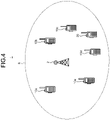
- FIG. 4 and FIG. 5 are conceptual diagrams for explaining the specific example of the wireless communication system according to the first embodiment of the present disclosure.
- FIG. 4 illustrates an example in which a wireless communication device 20 belonging to another group different from a group of the wireless communication device 10 is present within the transmission enabled range R of the wireless communication base station 2.
- the number of the wireless communication devices 20 belonging to the same group is not limited.
- FIG. 5 illustrates an example in which, among the wireless communication devices 10 belonging to the same group that perform group communication, the wireless communication device 10a is present outside the transmission enabled range R of the wireless communication base station 2.
- the wireless communication device 20 sharing the call channels (channel frequencies) with the group to which the wireless communication device 10a belongs, transmission of the wireless communication device 10a with which the user has performed the transmission starting operation cannot be started until group communication of the another group is completed and a vacant channel is generated in the call channels (channel frequencies).
- the wireless communication device 10 that shares the call channels (channel frequencies) with another group and performs group communication by unidirectional communication of PTT type via the wireless communication base station 2, for example, there is a possibility that the transmission content cannot be quickly transmitted due to a time lag from when the user performs the transmission starting operation until a vacant channel is generated in the call channels (channel frequencies) and transmission is actually started, or due to lowering of the radio wave intensity caused when the wireless communication device 10 is present outside the transmission enabled range of the wireless communication base station 2, for example.
- FIG. 6 is a flowchart illustrating an example of a procedure of a schematic process performed by the wireless communication system according to the first embodiment of the present disclosure.
- the wireless communication device 10a is assumed to be a transmission side device (one wireless communication device) and the wireless communication device 10b is assumed to be a reception side device (another wireless communication device).
- the wireless communication device 10a is assumed to be a transmission side device (one wireless communication device) and the wireless communication device 10b is assumed to be a reception side device (another wireless communication device).
- the wireless communication device 10a as the transmission side device.
- Step S1 When the transmission starting operation is performed by the wireless communication device 10a (Step S1), the wireless communication device 10a performs a process of determining whether the voice data collected by the microphone 17 (hereinafter, also referred to as real-time data) can be transmitted (a process of determining whether real-time data transmission can be performed) (Step S2) .
- the wireless communication device 10a performs a process of determining whether the voice data collected by the microphone 17 (hereinafter, also referred to as real-time data) can be transmitted (a process of determining whether real-time data transmission can be performed) (Step S2) .
- the wireless communication device 10a starts real-time transmission of the voice data collected by the microphone 17 (Step S3).
- the wireless communication device 10a stops the real-time transmission of the voice data collected by the microphone 17 (Step S5).
- the wireless communication device 10a When the real-time data cannot be transmitted, the wireless communication device 10a starts to record voice data collected by the microphone 17 (Step S6).
- the wireless communication device 10a stops the recording of the voice data collected by the microphone 17 (Step S8), and performs a transmission process for the voice recording data (a voice recording data transmission process) (Step S10) after a process of determining whether the voice recording data can be transmitted (a process of determining whether voice recording data transmission can be performed) (Step S9).
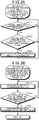
- FIG. 7 is a flowchart illustrating an example of a procedure for the process of determining whether real-time data transmission can be performed by the transmission side device.
- FIG. 8 is a flowchart illustrating an example of a procedure for the process of determining whether real-time data transmission can be performed by the wireless communication base station.
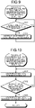
- FIG. 9 is a flowchart illustrating an example of a procedure for the process of determining whether real-time data transmission can be performed by the reception side device.
- the wireless communication device 10a is assumed to be in a detection standby state for the transmission starting operation
- the wireless communication base station 2 is assumed to be in a reception standby state for a real-time data transmission request by the wireless communication device 10a
- the wireless communication device 10b is assumed to be in a reception standby state for a real-time data transmission request by the wireless communication base station 2.
- the determination unit 170 of the wireless communication device 10a determines whether transmission can be performed by the communication unit 12 as illustrated in FIG. 7 (Step S201). Specifically, the determination unit 170 of the wireless communication device 10a acquires a reception state of the communication unit 12, and if there is no received radio wave in one of the call channels (one of the channel frequencies) stored in the storage 13, the determination unit 170 determines that transmission can be performed by using the one of the call channels (the one of the channel frequency) (Yes at Step S201). If there are received radio waves in all of the call channels (channel frequencies) stored in the storage 13, the determination unit 170 of the wireless communication device 10a determines that transmission cannot be performed (No at Step S201).
- the determination unit 170 of the wireless communication device 10a determines that real-time data transmission cannot be performed (Step S202).
- the communication controller 163 of the wireless communication device 10a controls the communication unit 12 to make a real-time data transmission request to the wireless communication base station 2 (Step S203).
- the wireless communication device 10a may transmit the positional information, the identification information such as the identification ID, and the like thereof.
- the identification information such as the identification ID, the positional information, and the like thereof may be periodically transmitted.
- the determination unit 170 of the wireless communication device 10a may determine whether to make the real-time data transmission request by the radio wave intensity received by the communication unit 12 from the wireless communication base station 2 as an indicator of the determination. Alternatively, the determination unit 170 of the wireless communication device 10a may determine whether to make the real-time data transmission request based on the positional information, a battery residual amount, an average value of a transmission arrival distance, and the like of the wireless communication device 10a.
- the determination unit 267 of the wireless communication base station 2 determines whether the real-time data transmission request by the wireless communication device 10a is received (Step S211). If the real-time data transmission request by the wireless communication device 10a is not received (No at Step S211), the determination unit 267 of the wireless communication base station 2 repeatedly performs the process at Step S211 until the real-time data transmission request by the wireless communication device 10a is received.
- the determination unit 267 of the wireless communication base station 2 determines whether the wireless communication device 10a is present within the transmission enabled range of the wireless communication base station 2 stored in the storage 23 (Step S212). If the wireless communication device 10a is not present within the transmission enabled range of the wireless communication base station 2 (No at Step S212), the process returns to Step S211, and the wireless communication base station 2 returns to the reception standby state for the real-time data transmission request by the wireless communication device 10a.
- the communication controller 263 of the wireless communication base station 2 controls the communication unit 12 to make the real-time data transmission request to the wireless communication device 10b (Step S213).
- the wireless communication base station 2 may also make a transmission request for the identification information such as the identification ID, the positional information, and the like of the wireless communication device 10b.
- the determination unit 267 of the wireless communication base station 2 may determine whether to make the real-time data transmission request by the radio wave intensity between the wireless communication device 10b and itself as an indicator of the detemination. Alternatively, the determination unit 267 of the wireless communication base station 2 may determine whether to make the real-time data transmission request based on the positional information, a battery residual amount, an average value of a transmission arrival distance, and the like of the wireless communication device 10b received from the wireless communication device 10b.
- the determination unit 170 of the wireless communication device 10b determines whether the real-time data transmission request by the wireless communication base station 2 is received (Step S221). If the real-time data transmission request by the wireless communication base station 2 is not received (No at Step S221), the determination unit 170 of the wireless communication device 10b repeatedly performs the process at Step S221 until the real-time data transmission request by the wireless communication base station 2 is received.
- the communication controller 163 of the wireless communication device 10b controls the communication unit 12 to give a notification of permitting real-time data transmission to the wireless communication base station 2 (Step S222).
- the wireless communication device 10b may transmit the identification information such as the identification ID, the positional information, and the like thereof.
- the identification information such as the identification ID, the positional information, and the like thereof may be periodically transmitted.
- the determination unit 267 of the wireless communication base station 2 determines whether the notification of permitting real-time data transmission from the wireless communication device 10b is received (Step S214).
- Step S217 when the notification of permitting real-time data transmission is not received after a predetermined time has elapsed from the real-time data transmission request, the process may return to Step S211, and the wireless communication base station 2 may return to the reception standby state for the real-time data transmission request by the wireless communication device 10a.
- the determination unit 267 of the wireless communication base station 2 determines whether the wireless communication device 10b is present within the transmission enabled range of the wireless communication base station 2 stored in the storage 23 (Step S215). If the wireless communication device 10b is not present within the transmission enabled range of the wireless communication base station 2 (No at Step S215), the process returns to Step S211, and the wireless communication base station 2 returns to the reception standby state for the real-time data transmission request by the wireless communication device 10a.
- the communication controller 263 of the wireless communication base station 2 controls the communication unit 22 to give the notification of permitting real-time data transmission to the wireless communication device 10a (Step S216).
- the determination unit 170 of the wireless communication device 10a determines whether the notification of permitting real-time data transmission from the wireless communication base station 2 is received (Step S204). If the notification of permitting real-time data transmission from the wireless communication base station 2 is not received (No at Step S204), the determination unit 170 of the wireless communication device 10a adds 1 to a counter value C1 (Step S206), and determines whether the counter value C1 has become a counter threshold C1th (Step S207). If the counter value C1 is not the counter threshold C1th (No at Step S207), the process returns to Step S203.
- the determination unit 170 of the wireless communication device 10a determines that real-time data transmission can be performed (Step S205).
- Step S3 the communication controller 163 of the wireless communication device 10a starts to transmit the real-time data from the communication unit 12 (Step S3).
- the output destination of the voice data collected by the microphone 17 (real-time data) is switched to the communication unit 12 by the voice data switching unit 168 of the wireless communication device 10a.
- the communication controller 163 of the wireless communication device 10a stops the transmission of the real-time data from the communication unit 12 (Step S5).
- Step S2 the storage controller 164 of the wireless communication device 10a starts to record the voice data in the storage 13 (Step S6).
- the output destination of the voice data collected by the microphone 17 (real-time data) is switched to the storage 13 by the voice data switching unit 168 of the wireless communication device 10a.
- the storage controller 164 of the wireless communication device 10a stops the recording of the voice data into the storage 13 (Step S8).
- FIG. 10 is a flowchart illustrating an example of a procedure for the process of determining whether voice recording data transmission can be performed by the transmission side device.
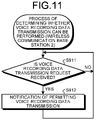
- FIG. 11 is a flowchart illustrating an example of a procedure for the process of determining whether voice recording data transmission can be performed by the wireless communication base station.
- the wireless communication device 10a is assumed to be in a transmission standby state for the voice recording data
- the wireless communication base station 2 is assumed to be in a reception standby state for the voice recording data transmission request by the wireless communication device 10a.
- the communication controller 163 of the wireless communication device 10a controls the communication unit 12 to make thr voice recording data transmission request to the wireless communication base station 2 (Step S901).
- the wireless communication device 10a may transmit the identification information such as the identification ID, the positional information, and the like thereof.
- the identification information such as the identification ID, the positional information, and the like thereof may be periodically transmitted.
- the determination unit 170 of the wireless communication device 10a may determine whether to make the voice recording data transmission request by the radio wave intensity between the wireless communication base station 2 and itself as an indicator of the determination. Alternatively, the determination unit 170 of the wireless communication device 10a may determine whether to make the voice recording data transmission request based on the positional information, a battery residual amount, an average value of a transmission arrival distance, and the like thereof.
- the determination unit 267 of the wireless communication base station 2 determines whether the voice recording data transmission request by the wireless communication device 10a is received (Step S911). If the voice recording data transmission request by the wireless communication device 10a is not received (No at Step S911), the determination unit 267 of the wireless communication base station 2 repeatedly performs the process at Step S911 until the voice recording data transmission request by the wireless communication device 10a is received.
- the communication controller 263 of the wireless communication base station 2 controls the communication unit 22 to give the notification of permitting voice recording data transmission to the wireless communication device 10a (Step S912).
- the determination unit 170 of the wireless communication device 10a determines whether the notification of permitting voice recording data transmission from the wireless communication base station 2 is received (Step S902). If the notification of permitting voice recording data transmission from the wireless communication base station 2 is not received (No at Step S902), the process returns to Step S901, and the wireless communication device 10a returns to the transmission standby state for the voice recording data.
- Step S903 If the notification of permitting voice recording data transmission is received from the wireless communication base station 2 (Yes at Step S902), the determination unit 170 of the wireless communication device 10a determines that voice recording data transmission can be performed (Step S903).
- Step S9 If it is determined that voice recording data transmission can be performed at Step S9 (Step S903 in FIG. 10 ), the process proceeds to the transmission process (Step S10) for the voice data (voice recording data) stored in the storage 13.
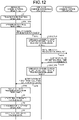
- FIG. 12 and FIG. 13 are sequence diagrams illustrating a specific example of the processes performed by the wireless communication system according to the first embodiment of the present disclosure.
- Step S1 in FIG. 6 when the transmission starting operation is performed by the wireless communication device 10a (Step S1 in FIG. 6 ), in a case in which the wireless communication device 10a as the transmission side device can perform the transmission (Yes at Step S201 in FIG. 7 ) and is present within the transmission enabled range of the wireless communication base station 2 (Yes at Step S212 in FIG. 8 ), and the wireless communication device 10b as the reception side device is present within the transmission enabled range of the wireless communication base station 2 (Yes at Step S215 in FIG. 8 ), it is determined that the voice data (real-time data) collected by the microphone 17 can be transmitted (Step S205 in FIG. 7 ), and the real-time data is transmitted (Steps S3, S4, and S5 in FIG. 6 ).
- Step S1 in FIG. 6 when the transmission starting operation is performed by the wireless communication device 10a (Step S1 in FIG. 6 ), in a case in which the wireless communication device 10a as the transmission side device cannot perform transmission (No at Step S201 in FIG. 7 ), it is determined that the voice data (real-time data) collected by the microphone 17 cannot be transmitted (Step S202 in FIG. 7 ), the real-time data is recorded (S6, S7, and S8 in FIG. 6 ), and the voice recording data is transmitted to the wireless communication base station 2 (Step S10 in FIG. 6 ) after determining whether the voice recording data can be transmitted (Step S9 in FIG. 6 ).
- the wireless communication device 10a when the wireless communication device 10a is not present within the transmission enabled range of the wireless communication base station 2 (No at Step S212 in FIG. 8 ), or when the wireless communication device 10b is not present within the transmission enabled range of the wireless communication base station 2 (No at Step S215 in FIG. 8 ), it is determined that the voice data (real-time data) collected by the microphone 17 cannot be transmitted (Step S202 in FIG. 7 ), the real-time data is recorded (S6, S7, and S8 in FIG. 6 ), and the voice recording data is transmitted to the wireless communication base station 2 (Step S10 in FIG. 6 ) after determining whether the voice recording data can be transmitted (Step S9 in FIG. 6 ).
- the voice data (real-time data) collected by the microphone 17 is recorded in a situation in which transmission is not actually started although the user performs the transmission starting operation, or transmission content is lost due to lowering of the radio wave intensity, the situation including a case in which the call channel is used by another group sharing the call channels (channel frequencies) with the group to which the wireless communication device 10 belongs, a case in which the wireless communication device 10a as the transmission side device is out of the transmission enabled range of the wireless communication base station 2, a case in which the wireless communication device 10b as the reception side device is out of the transmission enabled range of the wireless communication base station 2, or the like.
- the recorded voice data (voice recording data) is transmitted after determining whether the voice recording data can be transmitted.
- FIG. 14 is a flowchart illustrating an example of a procedure for the voice recording data transmission process performed by the transmission side device.
- the output destination of the voice data (voice recording data) stored in the storage 13 is assumed to be switched to the communication unit 12 by the voice data switching unit 168 of the wireless communication device 10a.
- Step S9 illustrated in FIG. 6 after it is determined that voice recording data transmission can be performed (Step S903 in FIG. 10 ), the communication quality measuring unit 169 of the wireless communication device 10a measures the BER of the communication unit 12 (Step S1001).
- the determination unit 170 of the wireless communication device 10a compares the BER measured by the communication quality measuring unit 169 with the first threshold stored in the storage 13. Specifically, the determination unit 170 of the wireless communication device 10a determines whether the BER measured by the communication quality measuring unit 169 is smaller than the first threshold (BER ⁇ first threshold) (Step S1002).
- the determination unit 170 of the wireless communication device 10a determines whether the BER measured by the communication quality measuring unit 169 is smaller than the second threshold, which is larger than the first threshold (BER ⁇ second threshold) (Step S1004).
- the BER measured by the communication quality measuring unit 169 is equal to or larger than the second threshold (BER ⁇ second threshold) (No at Step S1004), the process returns to Step S1001.
- the communication controller 163 of the wireless communication device 10a controls the communication unit 12 to transmit a piece of divided data having a predetermined length from a head of the voice data (voice recording data) stored in the storage 13 (Step S1005).
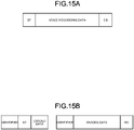
- FIG. 15A is a schematic diagram of the voice recording data stored in the storage of the wireless communication device.
- FIG. 15B is a schematic diagram of the divided data illustrating a division example of the voice recording data transmitted from the communication unit of the wireless communication device.
- the voice data stored in the storage 13 of the wireless communication device 10 includes a start code ST added by the transmission starting operation and an end code ED added by the transmission stopping operation.
- an identifier such as identification information such as the identification ID and the positional information of the wireless communication device is added to the divided data transmitted at Step S1005.
- the determination unit 170 of the wireless communication device 10a determines whether residual voice recording data after the divided data is transmitted at Step S1005 is present (Step S1006). If the residual voice recording data after the divided data is transmitted at Step S1005 is present in the storage 13 (Yes at Step S1006), the process returns to Step S1001.
- the communication controller 163 of the wireless communication device 10a controls the communication unit 12 to transmit the residual voice recording data after the divided data is transmitted at Step S1005 (Step S1003).
- the BER that is firstly measured after the voice data is recorded in the storage 13 is smaller than the first threshold, the entire voice recording data may be transmitted without being divided.
- Step S1004 If the BER measured by the communication quality measuring unit 169 is equal to or larger than the second threshold (BER ⁇ second threshold) at Step S1004 of the voice recording data transmission processing illustrated in FIG. 14 (No at Step S1004), transmission processing for the voice recording data remaining in the storage 13 is temporarily stopped. Thereafter, when the BER measured by the communication quality measuring unit 169 becomes smaller than the second threshold (BER ⁇ second threshold) at Step S1004 of the voice recording data transmission processing illustrated in FIG. 14 (Yes at Step S1004), the transmission processing for the voice recording data remaining in the storage 13 is started again.
- the second threshold BER ⁇ second threshold
- FIG. 16 is a flowchart illustrating an example of a procedure for the voice recording data storage process performed by the wireless communication base station.
- the determination unit 267 of the wireless communication base station 2 determines whether the voice recording data is divided data, the voice recording data being transmitted from the wireless communication device 10a in the voice recording data transmission process illustrated in FIG. 14 and received by the communication unit 22 of the wireless communication base station 2 (Step S1011). Specifically, for example, the determination unit 267 of the wireless communication base station 2 determines whether the identifier is added to the data, and determines that the data is the divided data if the identifier is added to the data.
- the storage controller 264 of the wireless communication base station 2 performs a control so that the voice recording data received by the communication unit 22 is stored in the storage 23 (Step S1013) .
- the data restoration unit 268 of the wireless communication base station 2 successively combines pieces of the divided data received by the communication unit 22 on a time-series basis, and restores the original voice recording data before being divided in the voice recording data transmission processing illustrated in FIG. 14 (Step S1012). Specifically, for example, the data restoration unit 268 of the wireless communication base station 2 combines a series of pieces of the divided data on a time-series basis based on the identifier added to the divided data, and restores the original voice recording data before being divided in the voice recording data transmission process illustrated in FIG. 14 .
- the storage controller 264 of the wireless communication base station 2 performs a control so that the voice recording data restored by the data restoration unit 268 is stored in the storage 23 (Step S1013) .
- FIG. 17 is a flowchart illustrating an example of a procedure for the voice recording data relay process performed by the wireless communication base station.
- FIG. 18 is a flowchart illustrating an example of a procedure for the process of determining whether voice recording data transmission can be performed by the reception side device.
- the communication controller 263 of the wireless communication base station 2 controls the communication unit 22 to make a voice recording data transmission request to the wireless communication device 10b as the reception side device (Step S1014).
- the wireless communication base station 2 may also make a transmission request for the identification information such as the identification ID, the positional information, and the like thereof.
- the determination unit 267 of the wireless communication base station 2 may determine whether to make the voice recording data transmission request by the radio wave intensity between the wireless communication device 10b and itself as an indicator of the determination. Alternatively, the determination unit 267 of the wireless communication base station 2 may determine whether to make the voice recording data transmission request based on the positional information, a battery residual amount, an average value of a transmission arrival distance, and the like thereof received from the wireless communication device 10b.
- the determination unit 170 of the wireless communication device 10b determines whether the voice recording data transmission request by the wireless communication base station 2 is received (Step S1021). If the voice recording data transmission request by the wireless communication base station 2 is not received (No at Step S1021), the determination unit 170 of the wireless communication device 10b repeatedly performs the process at Step S1021 until the voice recording data transmission request by the wireless communication base station 2 is received.
- the communication controller 163 of the wireless communication device 10b controls the communication unit 12 to give the notification of permitting voice recording data transmission to the wireless communication base station 2 (Step S1022).
- the wireless communication device 10b may transmit the identification information such as the identification ID, the positional information, and the like thereof.
- the identification information such as the identification ID, the positional information, and the like thereof may be periodically transmitted.
- the determination unit 267 of the wireless communication base station 2 determines whether the notification of permitting voice recording data transmission from the wireless communication device 10b is received (Step S1015). If the notification of permitting voice recording data transmission from the wireless communication device 10b is not received (No at Step S1015), the process returns to Step S1014.
- Step S1015 If the notification of permitting voice recording data transmission from the wireless communication device 10b is received (Yes at Step S1015), subsequently, the determination unit 267 of the wireless communication base station 2 determines whether the wireless communication device 10b is present within the transmission enabled range of the wireless communication base station 2 stored in the storage 23 (Step S1016). If the wireless communication device 10b is not present within the transmission enabled range of the wireless communication base station 2 (No at Step S1016), the process returns to Step S1014.
- the communication controller 263 of the wireless communication base station 2 controls the communication unit 22 to transmit the voice recording data to the wireless communication device 10b (Step S1017).
- FIG. 19 is a sequence diagram illustrating a specific example of the process performed by the wireless communication system according to the first embodiment of the present disclosure.
- Step S1014 in FIG. 17 when the wireless communication base station 2 makes the voice recording data transmission request to the wireless communication device 10b as the reception side device (Step S1014 in FIG. 17 ), if the wireless communication device 10b is present within the transmission enabled range of the wireless communication base station 2 (Yes at Step S1016 in FIG. 17 ), it is determined that the voice recording data can be transmitted, and the voice recording data is transmitted from the wireless communication base station 2 to the wireless communication device 10b (Step S1017 in FIG. 17 ).
- the wireless communication device 10b is not present within the transmission enabled range of the wireless communication base station 2 (No at Step S1016 in FIG. 17 ), it is determined that the voice recording data cannot be transmitted, and the voice recording data is not transmitted from the wireless communication base station 2 to the wireless communication device 10b.
- transmission content can be quickly transmitted through the respective processes including the process of determining whether real-time data transmission can be performed ( FIG. 7 , FIG. 8 , and FIG. 9 ), the process of determining whether voice recording data transmission can be performed ( FIG. 10 and FIG. 11 ), the voice recording data transmission process ( FIG. 14 ), the voice recording data storage process ( FIG. 16 ), and the voice recording data relay process ( FIG. 17 and FIG. 18 ) described above in the first embodiment of the present disclosure.
- a real-time data transmission request is made in a case of the real-time data transmission
- the voice recording data transmission request is made in a case of the voice recording data transmission.
- a common voice data transmission request is made in both cases.
- the real-time data and the voice recording data may be collectively referred to as voice data.
- the present modification is an example assuming that there is no other group sharing the call channels (channel frequencies) with the group to which the wireless communication device 10 belongs in the wireless communication system 1. That is, when the wireless communication device 10a as the transmission side device makes a transmission start request, it is determined that transmission cannot be performed in a case in which the wireless communication device 10a is out of the transmission enabled range of the wireless communication base station 2, and it is determined that transmission can be performed in a case in which the wireless communication device 10a is present within the transmission enabled range of the wireless communication base station 2.
- the present modification also assumes a case in which the wireless communication device 10b as the reception side device is present within the transmission enabled range of the wireless communication base station 2. Thus, this is a case in which transmission can be performed if the wireless communication device 10a is present within the transmission enabled range of the wireless communication base station 2, and transmission cannot be performed if the wireless communication device 10a is present outside thereof.
- Step S1 the wireless communication device 10a performs a process of determining whether the voice data collected by the microphone 17 can be transmitted (Step S2), and makes a voice data transmission request to the wireless communication base station 2 (Step S203) since it is determined that transmission can be performed (Step S201).
- the wireless communication base station 2 When receiving the voice data transmission request, the wireless communication base station 2 gives a notification of permitting voice data transmission to the wireless communication device 10a (Step S216) since the wireless communication device 10a is present within the transmission enabled range of the wireless communication base station 2 (Yes at Step S212), and the wireless communication device 10b is present within the transmission enabled range of the wireless communication base station 2 (Yes at Step S215) similarly to the first embodiment.
- the wireless communication device 10a When receiving the notification of permitting voice data transmission from the wireless communication base station 2, the wireless communication device 10a starts real-time transmission of the voice data collected by the microphone 17 (Step S3).
- the wireless communication device 10a causes the voice data to include the positional information of the wireless communication device 10a that is acquired at the time when the real-time transmission is started.
- the wireless communication base station 2 receives the voice data, and acquires the positional information included in the voice data.
- the wireless communication base station 2 determines whether the acquired positional information is within the transmission enabled range of the wireless communication base station 2.
- the acquired positional information is within the transmission enabled range, so that the wireless communication base station 2 transmits the voice data to the wireless communication device 10b.
- Step S6 recording of the voice data collected by the microphone 17 is started.
- the wireless communication device 10a causes the voice recording data to include the positional information of the wireless communication device 10a at the time when recording of the voice data is started.
- the wireless communication device 10a measures the BER, and transmits the divided data in accordance with the BER similarly to the first embodiment.
- the identification information and the positional information are added to each piece of the divided data.
- the wireless communication device 10a transmits the voice recording data using the same method as that in the first embodiment.
- the wireless communication base station 2 acquires the positional information included in the received voice data.
- the wireless communication base station 2 determines whether the acquired positional information is within the transmission enabled range of the wireless communication base station 2.
- the positional information added to the voice data is out of the transmission enabled range, so that it is determined that the received voice data is divided data (divided voice recording data).
- the wireless communication base station 2 successively receives pieces of the divided data using the same method as that in the first embodiment to restore the original voice recording data before being divided, and performs a relay process for the voice recording data.
- the wireless communication device 10 makes a common transmission request for real-time data transmission and voice recording data transmission
- the wireless communication base station 2 receives the voice data of real-time data transmission and the voice data of voice recording data transmission bt a common transmission request, and whether the data is real-time data or voice recording data is determined based on the positional information in the voice data, so that the entire process performed by the communication system can be simplified.
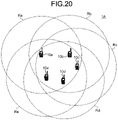
- FIG. 20 is a conceptual diagram for explaining the configuration of the wireless communication system according to the second embodiment of the present disclosure.
- a wireless communication system 1A includes, for example, the wireless communication device 10a, the wireless communication device 10b, the wireless communication device 10c, the wireless communication device 10d, and the wireless communication device 10e.
- Each of the wireless communication device 10a to the wireless communication device 10e belongs to the same group.
- the wireless communication device 10a to the wireless communication device 10e perform group communication with each other by unidirectional communication of a Push to Talk (PTT) type.
- FIG. 20 illustrates an example in which the wireless communication device 10a to the wireless communication device 10e that perform group communication are present within each other's transmission enabled ranges Ra, Rb, Rc, Rd, and Re.
- each of the transmission enabled ranges Ra, Rb, Rc, Rd, and Re indicates a range in which a predetermined radio wave intensity required for performing stable transmission/reception between the respective wireless communication devices can be obtained.
- the wireless communication device 10a to the wireless communication device 10e perform group communication while appropriately switching between the call channels (channel frequencies).
- the call channels (channel frequencies) used for performing the group communication by the wireless communication device 10a to the wireless communication device 10e are shared with another group that is different from the group to which the wireless communication device 10a to the wireless communication device 10e belong.
- the wireless communication device 10a to the wireless communication device 10e may be collectively referred to as a wireless communication device 10A.
- the number of wireless communication devices 10A belonging to the same group is not limited.
- FIG. 21 is a block diagram illustrating an example of the configuration of the wireless communication device according to the second embodiment of the present disclosure.
- the wireless communication device 10A includes the GPS reception unit 11, the communication unit 12, a storage 13A, the operation unit 14, the display 15, a controller 16A, and the microphone 17.
- the wireless communication device 10A illustrated in FIG. 21 is a wireless communication device having a group communication function by unidirectional communication of PTT type.
- the GPS reception unit 11, the communication unit 12, the operation unit 14, the display 15, and the microphone 17 are the same constituent parts as those in the first embodiment, so that description thereof will not be repeated.
- the storage 13A stores the voice data transmitted/received among the wireless communication devices in the group in addition to the function of the storage 13 of the wireless communication device 10 according to the first embodiment.
- the voice data transmitted/received among the wireless communication devices in the group is stored together with the positional information received from each of the wireless communication devices in the group by the communication unit 12.
- the storage 13A stores the transmission enabled range of each of the wireless communication devicees (for example, the transmission enabled ranges Ra, Rb, Rc, Rd, and Re illustrated in FIG. 20 ) .
- the controller 16A includes the device information acquisition unit 161, the positional information acquisition unit 162, the communication controller 163, a storage controller 164A, the operation controller 165, the display controller 166, the voice processing unit 167, the voice data switching unit 168, the communication quality measuring unit 169, a determination unit 170A, and a data restoration unit 171.
- the device information acquisition unit 161, the positional information acquisition unit 162, the communication controller 163, the operation controller 165, the display controller 166, the voice processing unit 167, the voice data switching unit 168, and the communication quality measuring unit 169 are the same constituent parts as those in the first embodiment, so that description thereof will not be repeated.
- the storage controller 164A stores, in the storage 23, the voice data transmitted from each of the wireless communication devices in the group together with the positional information of each of the wireless communication devices, for example, in addition to the function of the storage controller 164 of the wireless communication device 10 according to the first embodiment.
- the storage controller 164A also reads out the transmission enabled range of each of the wireless communication device stored in the storage 13A, for example, in addition to the function of the storage controller 164 of the wireless communication device 10 according to the first embodiment.
- the determination unit 170A performs various kinds of determination processes in the wireless communication device 10A. Specifically, for example, the determination unit 170A determines whether each of the wireless communication devices in the group is present within the transmission enabled range of the device thereof (for example, the transmission enabled ranges Ra, Rb, Rc, Rd, and Re illustrated in FIG. 20 ). In the present disclosure, for example, the determination unit 170A determines whether each of the wireless communication devices in the group is present within the transmission enabled range of the device thereof based on the transmission enabled range of the device thereof read out from the storage 13A and the positional information of each of the wireless communication devices in the group.
- the transmission enabled range of the device thereof for example, the transmission enabled ranges Ra, Rb, Rc, Rd, and Re illustrated in FIG. 20 .
- the determination unit 170A determines whether each of the wireless communication devices in the group is present within the transmission enabled range of the device thereof based on the transmission enabled range of the device thereof read out from the storage 13A and the positional information of each of the wireless communication
- determination process performed by the determination unit 170A will be described later in detail in a process of determining whether real-time data transmission can be performed, a process of determining whether voice recording data transmission can be performed, a voice recording data transmission process, and a voice recording data relay process.
- the data restoration unit 171 has a function equivalent to that of the data restoration unit 268 in the controller 26 of the wireless communication base station 2 according to the first embodiment. Specifically, when the voice data received by the communication unit 12 is divided into multiplr pieces of divided data, the data restoration unit 171 combines the multiplr pieces of divided data to restore the original voice data. Specific examples of the voice data restoration process performed by the data restoration unit 171 will be described later in detail in a voice recording data storage/reproduction process (described later).
- FIG. 22 and FIG. 23 are conceptual diagrams for explaining the specific example of the wireless communication system according to the second embodiment of the present disclosure.
- FIG. 22 illustrates an example in which a wireless communication device 20 belonging to another group different from the group of the wireless communication device 10A is present within the transmission enabled ranges Ra, Rb, Rc, Rd, and Re of the respective wireless communication devices.
- the number of the wireless communication devices 20 belonging to the same group is not limited.
- FIG. 23 illustrates an example in which the wireless communication device 10a among the wireless communication devices 10A belonging to the same group that perform the group communication is present outside the transmission enabled ranges Rb, Rc, Rd, and Re of the respective wireless communication devices 10b, 10c, 10d, and 10e.
- the wireless communication device 10A that shares the call channels (channel frequencies) with another group and performs the group communication by unidirectional communication of PTT type, for example, there is a possibility that the transmission content cannot be quickly transmitted due to a time lag from when the user performs the transmission starting operation until a vacant channel is generated in the call channels (channel frequencies) and transmission is actually started, or due to lowering of the radio wave intensity caused when the wireless communication device 10A is present outside the transmission enabled ranges of the respective wireless communication devices, for example.
- a schematic process performed by the wireless communication system 1A according to the second embodiment of the present disclosure is the same as that in the first embodiment illustrated in FIG. 6 , so that the description thereof will not be repeated. Also in the second embodiment, in the following description, the wireless communication device 10a is assumed to be the transmission side device (one wireless communication device), and the wireless communication device 10b is assumed to be the reception side device (another wireless communication device) .
- FIG. 24 is a flowchart illustrating an example of a procedure for the process of determining whether real-time data transmission can be performed by the transmission side device.
- FIG. 25 is a flowchart illustrating an example of a procedure for the process of determining whether real-time data transmission can be performed by the reception side device.
- the same process as that in the first embodiment is denoted by the same reference numeral.
- the wireless communication device 10a is assumed to be in a detection standby state for the transmission starting operation, and the wireless communication device 10b is assumed to be in a reception standby state for a real-time data transmission request by the wireless communication device 10a.
- the determination unit 170A of the wireless communication device 10a determines whether transmission can be performed by the communication unit 12 as illustrated in FIG. 24 (Step S201). Specifically, if there is no received radio wave in one of the call channels (one of the channel frequencies) stored in the storage 13A, the determination unit 170A of the wireless communication device 10a determines that transmission can be performed by using the one of the call channels (the one of the channel frequencies) (Yes at Step S201). If there are received radio waves in all of the call channels (channel frequencies) stored in the storage 13A, the determination unit 170A of the wireless communication device 10a determines that transmission cannot be performed (No at Step S201).
- the determination unit 170 of the wireless communication device 10a determines that real-time data transmission cannot be performed (Step S202).
- the communication controller 163 of the wireless communication device 10a controls the communication unit 12 to make a real-time data transmission request to the wireless communication device 10b (Step S203A).
- the wireless communication device 10a may transmit the positional information, the identification information such as the identification ID, and the like thereof.
- the identification information such as the identification ID, the positional information, and the like thereof may be periodically transmitted.
- the determination unit 170A of the wireless communication device 10a may determine whether to make the real-time data transmission request by the wave intensity between the wireless communication device 10b and itself as an indicator of the etermination. Alternatively, the determination unit 170A of the wireless communication device 10a may determine whether to make the real-time data transmission request based on the positional information, a battery residual amount, an average value of a transmission arrival distance, and the like thereof.
- the determination unit 170A of the wireless communication device 10b determines whether the real-time data transmission request by the wireless communication device 10a is received (Step S221A). If the real-time data transmission request by the wireless communication device 10a is not received (No at Step S221A), the determination unit 170A of the wireless communication device 10b repeatedly performs the process at Step S221A until the real-time data transmission request by the wireless communication device 10a is received.
- Step S212A determines whether the wireless communication device 10a is present within the transmission enabled range thereof stored in the storage 13A. If the wireless communication device 10a is not present within the transmission enabled range thereof (No at Step S212A), the process returns to Step S221A, and the wireless communication device 10b returns to the reception standby state for the real-time data transmission request by the wireless communication device 10a.
- the communication controller 163 of the wireless communication device 10b controls the communication unit 12 to give the notification of permitting real-time data transmission to the wireless communication device 10a (Step S222A).
- the wireless communication device 10b may transmit the identification information such as the identification ID, the positional information, and the like thereof.
- the identification information such as the identification ID, the positional information, and the like thereof may be periodically transmitted.
- the determination unit 170A of the wireless communication device 10a determines whether the notification of permitting real-time data transmission from the wireless communication device 10b is received (Step S204A). If the notification of permitting real-time data transmission from the wireless communication device 10b is not received (No at Step S204A), the determination unit 170A of the wireless communication device 10a performs the process from Step S206 to Step S208. Instead of the process from Step S206 to Step S208, it may be determined that the real-time transmission cannot be performed in a case in which the notification of permitting real-time data transmission is not received after a predetermined time has elapsed from the real-time data transmission request.
- Step S204A If the notification of permitting real-time data transmission from the wireless communication device 10b is received (Yes at Step S204A), subsequently, the determination unit 170A of the wireless communication device 10a determines whether the wireless communication device 10b is present within the transmission enabled range thereof stored in the storage 13A (Step S215A). If the wireless communication device 10b is not present within the transmission enabled range thereof (No at Step S215), the process returns to Step S211, and the wireless communication device 10b returns to the reception standby state for the real-time data transmission request by the wireless communication device 10a.
- the determination unit 170A of the wireless communication device 10a determines that real-time data transmission can be performed (Step S205).
- Step S3 the communication controller 163 of the wireless communication device 10a starts to transmit the real-time data from the communication unit 12 (Step S3).
- the output destination of the voice data collected by the microphone 17 (real-time data) is switched to the communication unit 12 by the voice data switching unit 168 of the wireless communication device 10a.
- the communication controller 163 of the wireless communication device 10a stops the transmission of the real-time data from the communication unit 12 (Step S5) .
- Step S6 the storage controller 164A of the wireless communication device 10a starts to record the voice data into the storage 13A.
- the output destination of the voice data collected by the microphone 17 is switched to the storage 13A by the voice data switching unit 168 of the wireless communication device 10a.
- the storage controller 164A of the wireless communication device 10a stops the recording of the voice data into the storage 13A (Step S8).
- FIG. 26 is a flowchart illustrating an example of a procedure for the process of determining whether voice recording data transmission can be performed by the transmission side device.
- FIG. 27 is a flowchart illustrating an example of a procedure for the process of determining whether voice recording data transmission can be performed by the reception side device.
- the same process as that in the first embodiment is denoted by the same reference numeral.
- the wireless communication device 10a is assumed to be in the transmission standby state for the voice recording data
- the wireless communication device 10b is assumed to be in the reception standby state for the voice recording data transmission request by the wireless communication device 10a.
- the communication controller 163 of the wireless communication device 10a controls the communication unit 12 to make a voice recording data transmission request to the wireless communication device 10b (Step S901A).
- the wireless communication device 10a may transmit the identification information such as the identification ID, the positional information, and the like thereof.
- the identification information such as the identification ID, the positional information, and the like thereof may be periodically transmitted.
- the determination unit 170A of the wireless communication device 10a may determine whether to make the voice recording data transmission request by the radio wave intensity between the wireless communication device 10b and itself as an indicator of the determination. Alternatively, the determination unit 170A of the wireless communication device 10a may determine whether to make the voice recording data transmission request based on the positional information, a battery residual amount, an average value of a transmission arrival distance, and the like thereof.
- the determination unit 170A of the wireless communication device 10b determines whether the voice recording data transmission request by the wireless communication device 10a is received (Step S911A). If the voice recording data transmission request by the wireless communication device 10a is not received (No at Step S911A), the determination unit 170A of the wireless communication device 10b repeatedly performs the process at Step S911A until the voice recording data transmission request by the wireless communication device 10a is received.
- the communication controller 163 of the wireless communication device 10b controls the communication unit 22 to give the notification of permitting voice recording data transmission to the wireless communication device 10a (Step S912A).
- the determination unit 170A of the wireless communication device 10a determines whether the notification of permitting voice recording data transmission from the wireless communication device 10b is received (Step S902A). If the notification of permitting voice recording data transmission from the wireless communication device 10b is not received (No at Step S902A), the process returns to Step S901A, and the wireless communication device 10a returns to the transmission standby state for the voice recording data.
- Step S903 If the notification of permitting voice recording data transmission from the wireless communication device 10b is received (Yes at Step S902A), the determination unit 170A of the wireless communication device 10a determines that voice recording data transmission can be performed (Step S903).
- Step S9 If it is determined that voice recording data transmission can be performed at Step S9 (Step S903 in FIG. 10 ), the process proceeds to the transmission process (Step S10) for the voice data (voice recording data) stored in the storage 13.
- FIG. 28 and FIG. 29 are sequence diagrams illustrating a specific example of the process performed by the wireless communication system according to the second embodiment of the present disclosure.
- Step S1 in FIG. 6 when the transmission starting operation is performed by the wireless communication device 10a (Step S1 in FIG. 6 ), in a case in which the wireless communication device 10a as the transmission side device can perform the transmission (Yes at Step S201 in FIG. 24 ) and is present within the transmission enabled range of the wireless communication device 10b (Yes at Step S212A in FIG. 25 ), and in which the wireless communication device 10b as the reception side device is present within the transmission enabled range of the wireless communication device 10a (Yes at Step S215A in FIG. 24 ), it is determined that the voice data (real-time data) collected by the microphone 17 can be transmitted (Step S205 in FIG. 24 ), and the real-time data is transmitted (Steps S3, S4, and S5 in FIG. 6 ).
- Step S1 in FIG. 6 when the transmission starting operation is performed by the wireless communication device 10a (Step S1 in FIG. 6 ), in a case in which the wireless communication device 10a as the transmission side device cannot perform the transmission (Yes at Step S201 in FIG. 24 ), it is determined that the voice data (real-time data) collected by the microphone 17 cannot be transmitted (Step S202 in FIG. 24 ), the real-time data is recorded (S6, S7, and S8 in FIG. 6 ), and the voice recording data is transmitted to the wireless communication device 10b (Step S10 in FIG. 6 ) after determining whether the voice recording data can be transmitted (Step S9 in FIG. 6 ) .
- the wireless communication device 10a is not present within the transmission enabled range of the wireless communication device 10b (No at Step S212A in FIG. 25 ), or in a case in which the wireless communication device 10b is not present within the transmission enabled range of the wireless communication device 10a (No at Step S215A in FIG. 24 ), it is determined that the voice data (real-time data) collected by the microphone 17 cannot be transmitted (Step S202 in FIG. 24 ), the real-time data is recorded (S6, S7, and S8 in FIG. 6 ), and the voice recording data is transmitted to the wireless communication device 10b (Step S10 in FIG. 6 ) after determining whether the voice recording data can be transmitted (Step S9 in FIG. 6 ).
- the voice data (real-time data) collected by the microphone 17 is recorded in a situation in which transmission is not actually started although the user performs the transmission starting operation, or transmission content is lost due to lowering of the radio wave intensity, the situation including a case in which the call channel is used by another group sharing the call channel (channel frequency) with the group to which the wireless communication device 10 belongs, a case in which the wireless communication device 10a as the transmission side device is out of the transmission enabled range of the wireless communication device 10b as the reception side device, a case in which the wireless communication device 10b as the reception side device is out of the transmission enabled range of the wireless communication device 10a as the transmission side device, or the like.
- the recorded voice data (voice recording data) is transmitted after whether the voice recording data can be transmitted is determined.
- the voice recording data transmission process (Step S10 illustrated in FIG. 6 ) performed by the wireless communication device 10a as the transmission side device is the same process as that in the first embodiment illustrated in FIG. 14 , so that the description thereof will not be repeated.
- FIG. 30 is a flowchart illustrating an example of a procedure for a voice recording data storage/reproduction process performed by the reception side device.
- the determination unit 170A of the wireless communication device 10b determines whether the voice recording data is divided data, the voice recording data being transmitted from the wireless communication device 10a in the voice recording data transmission process illustrated in FIG. 14 and received by the communication unit 12 of the wireless communication device 10b (Step S1011A). Specifically, for example, the determination unit 170A of the wireless communication device 10b determines whether the identifier is added to the data, and determines that the data is divided data if the identifier is added to the data.
- the determination unit 170A of the wireless communication device 10b performs a control so that the voice recording data received by the communication unit 22 is stored in the storage 13A (Step S1013A).
- the data restoration unit 171 of the wireless communication device 10b successively combines pieces of the divided data received by the communication unit 12 on a time-series basis, and restores the original voice recording data before being divided in the voice recording data transmission process illustrated in FIG. 14 (Step S1012A). Specifically, for example, the data restoration unit 171 of the wireless communication device 10b combines a series of pieces of the divided data on a time-series basis based on the identifier added to the divided data, and restores the original voice recording data before being divided in the voice recording data transmission process illustrated in FIG. 14 .
- the storage controller 164A of the wireless communication device 10b performs a control so that the voice recording data restored by the data restoration unit 171 is stored in the storage 13A (Step S1013A). Thereafter, the voice recording data stored in the storage 13A is reproduced by a speaker (not illustrated) (Step S1014).
- transmission content can be quickly transmitted through the respective processes including the process of determining whether real-time data transmission can be performed ( FIG. 24 and FIG. 25 ), the process of determining whether voice recording data transmission can be performed ( FIG. 26 and FIG. 27 ), the voice recording data transmission process ( FIG. 14 ), and the voice recording data storage/reproduction process ( FIG. 30 ) described above in the second embodiment of the present disclosure.
- the embodiments of the present disclosure have been described above, but the present invention is not limited to the content of the embodiments.
- the constituent elements described above encompass a constituent element easily conceivable by those skilled in the art, substantially the same constituent element, and what is called an equivalent.
- the constituent elements described above can also be appropriately combined with each other.
- the constituent elements can be variously omitted, replaced, or modified without departing from the gist of the embodiments described above.
Landscapes
- Engineering & Computer Science (AREA)
- Signal Processing (AREA)
- Computer Networks & Wireless Communication (AREA)
- Multimedia (AREA)
- Quality & Reliability (AREA)
- Environmental & Geological Engineering (AREA)
- Human Computer Interaction (AREA)
- Health & Medical Sciences (AREA)
- Audiology, Speech & Language Pathology (AREA)
- Mobile Radio Communication Systems (AREA)
- Telephone Function (AREA)
- Telephonic Communication Services (AREA)
Abstract
Description
- The present invention relates to a wireless communication device, a wireless communication base station, and a wireless communication method.
- In a case in which a wireless communication terminal cannot perform transmission in a wireless communication system, there is known a technique of stopping normal transmission, recording transmission content in a memory, and then, when transmission is enabled thereafter, reproducing the transmission content recorded in the memory at high speed until the recorded transmission content catches up current transmission content to enable a smooth conversation without a lack of transmission content (for example, Patent Literature 1).
- Patent Literature 1:
Japanese Patent No. 3066311 - In
Patent Literature 1, a wireless communication base station monitors transmission signal strength from a wireless communication terminal, determines whether the wireless communication terminal is present within a service area thereof, and when the wireless communication terminal is out of the service area of the wireless communication base station, a wireless line control station transmits a transmission disabled signal to the wireless communication terminal via the wireless communication base station. That is, the technique disclosed inPatent Literature 1 has been developed assuming duplex communication (bidirectional communication) by which a radio wave condition can be monitored even during transmission. In the technique disclosed inPatent Literature 1, in a case in which a transmission disabled period from when transmission is disabled until transmission is enabled is prolonged, and a temporal delay caused in the transmission disabled period cannot be eliminated, the transmission content recorded in the memory needs to be cleared, that is, the transmission content in the transmission disabled period needs to be discarded. - On the other hand, for example, in simplex communication for performing unidirectional communication of what is called a Push to Talk (PTT) type while sharing a call channel with another group, when a communication channel used for transmission and reception within one group is used for communication of the another group, transmission cannot be started until communication of the another group is completed even when a user performs a transmission starting operation with a wireless terminal belonging to the one group. Furthermore, for example, when the user performs the transmission starting operation with the wireless terminal belonging to the one group outside a transmission enabled range of the wireless communication base station, there is a possibility that a radio wave intensity sufficient for performing stable transmission and reception cannot be obtained, and content desired to be transmitted cannot be quickly transmitted.
- The present disclosure provides a wireless communication device that can transmit transmission content quickly as much as possible, a wireless communication base station that relays the transmission content, and a wireless communication method that can transmit the transmission content quickly as much as possible when a favorable communication environment cannot be obtained. Solution to Problem
- According to one aspect, there is provided a wireless communication device comprising: a communication unit configured to transmit/receive signals to/from another wireless communication device using a channel frequency; a storage configured to store at least voice data collected by a microphone; an operation unit configured to detect a transmission starting operation and a transmission stopping operation; a communication quality measuring unit configured to measure a bit error rate indicating quality of communication using the channel frequency for each predetermined period; and a controller configured to control at least the communication unit and the storage in accordance with the transmission starting operation and the transmission stopping operation, wherein the controller is further configured to; control the storage to store, in a case in which the operation unit detects the transmission starting operation when the channel frequency is used by other wireless communication devices, the voice data until the operation unit detects the transmission stopping operation, control the communication unit to transmit, in a case in which the bit error rate measured by the communication quality measuring unit is smaller than a first threshold when the channel frequency is not used by other wireless communication devices, all pieces of voice data that have not been transmitted of the voice data stored in the storage, and control the communication unit to transmit, in a case in which the bit error rate is equal to or larger than the first threshold and smaller than a second threshold when the channel frequency is not used by other wireless communication devices, pieces of divided data having a predetermined length from a head of the voice data which has not been transmitted of the voice data stored in the storage.
- According to one aspect, there is provided a wireless communication base station configured to relay communication among multiple wireless communication devices, the wireless communication base station comprising: a communication unit configured to transmit/receive signals to/from the wireless communication devices; a storage in which at least a transmission enabled range of the wireless communication base station is stored; a determination unit configured to determine whether each of the wireless communication devices is present within the transmission enabled range based on positional information of each of the wireless communication devices received by the communication unit; and a controller configured to control at least the communication unit and the storage in accordance with a determination result obtained by the determination unit, wherein the controller is further configured to; perform control, in a case in which the wireless communication base station relays voice data that is transmitted from one wireless communication device to another wireless communication device of the wireless communication devices and the voice data transmitted from the one communication device is divided into multiple pieces of divided data, to successively combine the multiple pieces of divided data on a time-series basis, and to restore the voice data transmitted from the one wireless communication device to be stored in the storage, and control the communication unit, in a case in which the another wireless communication device is present within the transmission enabled range, to transmit the voice data stored in the storage to the another wireless communication device.
- According to one aspect, there is provided a wireless communication method comprising: storing voice data in a wireless communication device until a transmission stopping operation is detected after a transmission starting operation is detected when a channel frequency used for communication is used by other wireless communication devices; measuring a bit error rate indicating quality of communication using the channel frequency for each predetermined period; transmitting, in a case in which the bit error rate is smaller than a first threshold when the channel frequency is not used by other wireless communication devices, all pieces of voice data that have not been transmitted of the stored voice data; and transmitting, in a case in which the bit error rate is equal to or larger than the first threshold and smaller than a second thresholda when the channel frequency is not used by other wireless communication devices, pieces of divided data having a predetermined length from a head of the voice data that has not been transmitted of the stored voice data.
- According to the present disclosure, even when a favorable communication environment cannot be obtained, transmission content can be transmitted quickly as much as possible.
-
-
FIG. 1 is a conceptual diagram for explaining a wireless communication system according to a first embodiment of the present disclosure; -
FIG. 2 is a block diagram illustrating an example of a configuration of a wireless communication device according to the first embodiment of the present disclosure; -
FIG. 3 is a block diagram illustrating an example of a configuration of a wireless communication base station according to the first embodiment of the present disclosure; -
FIG. 4 is a conceptual diagram for explaining a specific example of the wireless communication system according to the first embodiment of the present disclosure; -
FIG. 5 is a conceptual diagram for explaining a specific example of the wireless communication system according to the first embodiment of the present disclosure; -
FIG. 6 is a flowchart illustrating an example of a procedure for a schematic process performed by the wireless communication system according to the first embodiment of the present disclosure; -
FIG. 7 is a flowchart illustrating an example of a procedure for a process of determining whether real-time data transmission can be performed by a transmission side device; -
FIG. 8 is a flowchart illustrating an example of a procedure for a process of determining whether real-time data transmission can be performed by the wireless communication base station; -
FIG. 9 is a flowchart illustrating an example of a procedure for a process of determining whether real-time data transmission can be performed by a reception side device; -
FIG. 10 is a flowchart illustrating an example of a procedure for a process of determining whether voice recording data transmission can be performed by the transmission side device; -
FIG. 11 is a flowchart illustrating an example of a procedure for a process of determining whether voice recording data transmission can be performed by the wireless communication base station; -
FIG. 12 is a sequence diagram illustrating a specific example of a process performed by the wireless communication system according to the first embodiment of the present disclosure; -
FIG. 13 is a sequence diagram illustrating a specific example of the process performed by the wireless communication system according to the first embodiment of the present disclosure; -
FIG. 14 is a flowchart illustrating an example of a procedure for a voice recording data transmission process performed by the transmission side device; -
FIG. 15A is a schematic diagram of voice recording data stored in a storage of the wireless communication device; -
FIG. 15B is a schematic diagram of divided data illustrating a division example of the voice recording data transmitted from a communication unit of the wireless communication device; -
FIG. 16 is a flowchart illustrating an example of a procedure for a voice recording data storage process performed by the wireless communication base station; -
FIG. 17 is a flowchart illustrating an example of a procedure for avoice recording data relay process performed by the wireless communication base station; -
FIG. 18 is a flowchart illustrating an example of a procedure for a determination process of determining whether voice recording data transmission can be performed by the reception side device; -
FIG. 19 is a sequence diagram illustrating a specific example of the process performed by the wireless communication system according to the first embodiment of the present disclosure; -
FIG. 20 is a conceptual diagram for explaining a configuration of a wireless communication system according to a second embodiment of the present disclosure; -
FIG. 21 is a block diagram illustrating an example of a configuration of a wireless communication device according to the second embodiment of the present disclosure; -
FIG. 22 is a conceptual diagram for explaining a specific example of the wireless communication system according to the second embodiment of the present disclosure; -
FIG. 23 is a conceptual diagram for explaining a specific example of the wireless communication system according to the second embodiment of the present disclosure; -
FIG. 24 is a flowchart illustrating an example of a procedure for a process of determining whether real-time data transmission can be performed by a transmission side device; -
FIG. 25 is a flowchart illustrating an example of a procedure for a process of determining whether real-time data transmission can be performed by a reception side device; -
FIG. 26 is a flowchart illustrating an example of a procedure for a process of determining whether voice recording data transmission can be performed by the transmission side device; -
FIG. 27 is a flowchart illustrating an example of a procedure for a process of determining whether voice recording data transmission can be performed by the reception side device; -
FIG. 28 is a sequence diagram illustrating a specific example of a process performed by the wireless communication system according to the second embodiment of the present disclosure; -
FIG. 29 is a sequence diagram illustrating a specific example of the process performed by the wireless communication system according to the second embodiment of the present disclosure; and -
FIG. 30 is a flowchart illustrating an example of a procedure for a voice recording data storage/reproduction process performed by the reception side device. Description of Embodiments - The following describes embodiments according to the present disclosure in detail with reference to the attached drawings. The present disclosure is not limited to the embodiments. When there are multiple embodiments, the present disclosure encompasses a combination of the embodiments. In the following embodiments, the same parts are denoted by the same reference numerals, and redundant description will not be repeated.
- With reference to
FIG. 1 , the following describes a configuration of a wireless communication system according to a first embodiment of the present disclosure.FIG. 1 is a conceptual diagram for explaining the configuration of the wireless communication system according to the first embodiment of the present disclosure. - As illustrated in
FIG. 1 , awireless communication system 1 according to the first embodiment of the present disclosure includes, for example, awireless communication device 10a, awireless communication device 10b, awireless communication device 10c, awireless communication device 10d, and awireless communication device 10e. Each of thewireless communication device 10a to thewireless communication device 10e belongs to the same group. - The
wireless communication device 10a to thewireless communication device 10e perform group communication with each other by unidirectional communication of a Push to Talk (PTT) type.FIG. 1 illustrates an example in which thewireless communication device 10a to thewireless communication device 10e that perform group communication are present within a transmission enabled range R of a wirelesscommunication base station 2. In the first embodiment of the present disclosure, the transmission enabled range R of the wirelesscommunication base station 2 indicates a range in which a predetermined radio wave intensity required for performing stable transmission/reception between the respective wireless communication devices can be obtained. - The
wireless communication device 10a to thewireless communication device 10e perform group communication while appropriately switching between multiple call channels (channel frequencies). The call channels (channel frequencies) used for performing group communication by thewireless communication device 10a to thewireless communication device 10e are shared with another group that is different from the group to which thewireless communication device 10a to thewireless communication device 10e belong. Hereinafter, thewireless communication device 10a to thewireless communication device 10e may be collectively referred to as awireless communication device 10. The number of thewireless communication devices 10 belonging to the same group is not limited. - Next, with reference to
FIG. 2 , the following describes a configuration of the wireless communication device according to the first embodiment of the present disclosure.FIG. 2 is a block diagram illustrating an example of the configuration of the wireless communication device according to the first embodiment of the present disclosure. - As illustrated in
FIG. 2 , thewireless communication device 10 includes aGPS reception unit 11, acommunication unit 12, astorage 13, anoperation unit 14, adisplay 15, acontroller 16, and amicrophone 17. Thewireless communication device 10 illustrated inFIG. 2 is a wireless communication device having a group communication function by unidirectional communication of PTT type. - The
GPS reception unit 11 is constituted of a GPS reception circuit, a GPS reception antenna, and the like, and receives GPS signals. TheGPS reception unit 11 outputs the received GPS signals to a positional information acquisition unit (a position measuring unit) 162. - The
communication unit 12 performs wireless communication with another wireless communication device by unidirectional communication of PTT type via the wirelesscommunication base station 2. Specifically, thecommunication unit 12 transmits various pieces of information to the other wireless communication device, and receives various pieces of information from the other wireless communication device. Specifically, the various pieces of information are various kinds of data including voice data, still image data, video data, and document data. In the present disclosure, the voice data may include myltiple pieces of divided data that are divided on a time-series basis. A type of data to be transmitted/received to/from the other wireless communication device by thecommunication unit 12 is not particularly limited. For example, thecommunication unit 12 may have a function of performing short-range wireless communication, or may have a function of performing long-range wireless communication. Alternatively, thecommunication unit 12 may perform wireless communication with the other wireless communication device without using the wirelesscommunication base station 2. Thecommunication unit 12 may be constituted of a communication circuit and the like. - The
storage 13 stores various pieces of information. For example, thestorage 13 stores group information about the group to which thewireless communication device 10 belongs. The group information may include positional information or identification information such as an identification ID of the other wireless communication device belonging to the group, the call channels (channel frequencies) used for the group communication, and the like. - In the present disclosure, the
storage 13 stores voice data collected by themicrophone 17. Additionally, in the present disclosure, thestorage 13 stores thresholds (a first threshold and a second threshold) for a bit error rate (hereinafter, referred to as a "BER") indicating a communication quality index of thecommunication unit 12. For example, thestorage 13 can be implemented by a semiconductor memory element such as a random access memory (RAM) and a flash memory, or a storage device such as a hard disk and a solid state drive. - The
operation unit 14 receives various operations for thecontroller 16. The various operations include, for example, an operation of switching between ON and OFF of a transmission function (a transmission starting operation and a transmission stopping operation in the present disclosure), and an operation of switching between a data transmission state and a data reception state. Theoperation unit 14 outputs, to anoperation controller 165, an operation signal corresponding to a received operation. For example, theoperation unit 14 can implement reception of a user's operation by a physical switch or a touch panel disposed on thedisplay 15. - The
display 15 displays various images constituting a user interface. In the present disclosure, for example, thedisplay 15 displays information for starting or stopping transmission. Thedisplay 15 is, for example, a display including a liquid crystal display (LCD), an organic Electro-Luminescence (EL) display, or the like. Thedisplay 15 may include, for example, a light emitting unit such as a light emitting diode (LED). - For example, the
controller 16 is implemented when a computer program stored in the storage (for example, a computer program according to the present disclosure, not illustrated) is executed by a central processing unit (CPU), a micro processing unit (MPU), or the like using a RAM or the like as a working area. Thecontroller 16 is a controller which may be implemented by an integrated circuit such as an application specific integrated circuit (ASIC) or a field programmable gate array (FPGA), for example. - The
microphone 17 converts, for example, voice input by utterance and the like into a voice signal. - The
controller 16 includes a deviceinformation acquisition unit 161, the positionalinformation acquisition unit 162, acommunication controller 163, astorage controller 164, theoperation controller 165, adisplay controller 166, avoice processing unit 167, a voicedata switching unit 168, a communicationquality measuring unit 169, and adetermination unit 170. - The device
information acquisition unit 161 acquires various pieces of information about the other wireless communication device. For example, the deviceinformation acquisition unit 161 acquires identification information such as an identification ID, positional information, and the like of the other wireless communication device received by thecommunication unit 12. The information acquired by the deviceinformation acquisition unit 161 is not limited thereto. - The positional
information acquisition unit 162 acquires current positional information of thewireless communication device 10. The positionalinformation acquisition unit 162 acquires, for example, the current positional information of thewireless communication device 10 based on GPS signals received by theGPS reception unit 11. - The
communication controller 163 controls communication between thewireless communication device 10 and the otherwireless communication device 10 belonging to the same group of thewireless communication device 10 by controlling thecommunication unit 12. Thecommunication controller 163 transmits/receives various kinds of data to/from the otherwireless communication device 10 by controlling thecommunication unit 12, for example. In the present disclosure, thecommunication controller 163 transmits/receives, for example, voice data collected by themicrophone 17 or voice data stored in thestorage 13 to/from the otherwireless communication device 10 by controlling thecommunication unit 12. - The
storage controller 164 stores various pieces of information in thestorage 13. For example, thestorage controller 164 stores, in thestorage 13, positional information and identification information such as an identification ID of the other wireless communication device acquired by the deviceinformation acquisition unit 161, a channel frequency that is currently used by the group, and the like. In the present disclosure, for example, thestorage controller 164 stores voice data collected by themicrophone 17 in thestorage 13. Thestorage controller 164 stores, for example, the positional information of thewireless communication device 10 in thestorage 13. - The
storage controller 164 reads out various pieces of information from thestorage 13. For example, thestorage controller 164 reads out the identification information such as the identification ID, the positional information, and the like of the other wireless communication device stored in thestorage 13. In the present disclosure, thestorage controller 164 reads out the voice data stored in thestorage 13, for example. For example, thestorage controller 164 reads out the positional information of thewireless communication device 10 stored in thestorage 13. - The
display controller 166 causes thedisplay 15 to display various images. Thedisplay controller 166 causes thedisplay 15 to display various images constituting the user interface, for example. In the present disclosure, for example, thedisplay controller 166 causes thedisplay 15 to display information for starting or stopping transmission. - The
voice processing unit 167 processes (for example, digitally converts or encrypts) the voice signal collected by themicrophone 17, to be output to the voicedata switching unit 168 as voice data for transmission. - The voice
data switching unit 168 performs a switching process for the voice data. Specifically, the voicedata switching unit 168 switches an output destination of the voice data collected by themicrophone 17 and processed by thevoice processing unit 167, between thecommunication unit 12 and thestorage 13. Additionally, the voicedata switching unit 168 switches an output source of the voice data to thecommunication unit 12 between thevoice processing unit 167 and thestorage 13. - The communication
quality measuring unit 169 measures communication quality of thecommunication unit 12. Specifically, the communicationquality measuring unit 169 measures the BER as the communication quality index of thecommunication unit 12, for example. A method of measuring the BER by the communicationquality measuring unit 169 is not particularly limited. - The
determination unit 170 performs various kinds of determination processes in thewireless communication device 10. Specific examples of the determination processes performed by thedetermination unit 170 will be described later in detail in a process of determining whether real-time data transmission can be performed, a process of determining whether voice recording data transmission can be performed, a voice recording data transmission process, and a voice recording data relay process. - Next, with reference to
FIG. 3 , the following describes a configuration of a wirelesscommunication base station 2 according to the first embodiment of the present disclosure.FIG. 3 is a block diagram illustrating an example of the configuration of the wireless communication base station according to the first embodiment of the present disclosure. - As illustrated in
FIG. 3 , the wirelesscommunication base station 2 includes a communication unit 22, a storage 23, and a controller 26. The wirelesscommunication base station 2 illustrated inFIG. 3 is a wireless communication base station having a function of relaying unidirectional communication among the wireless communication devices that perform group communication by unidirectional communication of PTT type. Hereinafter, the wireless communication devices that perform group communication by unidirectional communication of PTT type are also referred to as "wireless communication devices in the group". - The wireless
communication base station 2 relays group communication among the wireless communication devices in the group while the call channels (channel frequencies) are shared by multiple groups and the call channels (channel frequencies) are appropriately switched. - The communication unit 22 performs wireless communication with the wireless communication devices in the group. Specifically, the communication unit 22 relays various pieces of information transmitted/received among the wireless communication devices in the group. Specifically, the various pieces of information are various kinds of data including voice data, still image data, video data, and document data. A type of data to be relayed among the wireless communication devices by the communication unit 22 is not particularly limited. In the present disclosure, the communication unit 22 receives positional information of each of the wireless communication devices together with the voice data from each of the wireless communication devices in the group. The communication unit 22 may be constituted of a communication circuit and the like.
- The storage 23 stores various pieces of information. For example, the storage 23 stores group information about the group performing group communication. The group information may include positional information or identification information such as an identification ID of each of the wireless communication devices in the group, the call channels (channel frequencies) used for group communication, and the like. In the present disclosure, the storage 23 stores the voice data transmitted/received among the wireless communication devices in the group. The voice data transmitted/received among the wireless communication devices in the group is stored together with the positional information received from each of the wireless communication devices in the group by the communication unit 22. In the present disclosure, the storage 23 stores the transmission enabled range of the wireless communication base station 2 (for example, the transmission enabled range R illustrated in
FIG. 1 ). For example, the storage 23 can be implemented by a semiconductor memory element such as a random access memory (RAM) and a flash memory, or a storage device such as a hard disk and a solid state drive. - For example, the controller 26 is implemented when a computer program stored in the storage (for example, a computer program according to the present disclosure, not illustrated) is executed by a central processing unit (CPU), a micro processing unit (MPU), or the like using a RAM or the like as a working area. The controller 26 is a controller that may be implemented by an integrated circuit such as an application specific integrated circuit (ASIC) or a field programmable gate array (FPGA), for example.
- The controller 26 includes a device
information acquisition unit 261, a positionalinformation acquisition unit 262, acommunication controller 263, astorage controller 264, adetermination unit 267, and adata restoration unit 268. - The device
information acquisition unit 261 acquires various pieces of information about the wireless communication devices in the group. For example, the deviceinformation acquisition unit 261 acquires identification information such as an identification ID and positional information of each of the wireless communication devices in the group received by the communication unit 22, a channel frequency that is currently used by the group, and the like. The information acquired by the deviceinformation acquisition unit 261 is not limited thereto. - The positional
information acquisition unit 262 acquires current positional information of each of the wireless communication devices in the group. For example, the positionalinformation acquisition unit 262 acquires the current positional information of thewireless communication device 10 based on information transmitted from each of the wireless communication devices. - The
communication controller 263 controls communication among the wireless communication devices in the group by controlling the communication unit 22. For example, thecommunication controller 263 relays various kinds of data among the wireless communication devices in the group by controlling the communication unit 22. In the present disclosure, for example, thecommunication controller 263 relays the voice data transmitted from each of the wireless communication devices in the group among the wireless communication devices in the group by controlling the communication unit 22. - The
storage controller 264 stores various pieces of information in the storage 23. For example, thestorage controller 264 stores, in the storage 23, positional information and identification information such as an identification ID of each of the wireless communication devices in the group acquired by the deviceinformation acquisition unit 261, a channel frequency that is currently used by the group, and the like. In the present disclosure, for example, thestorage controller 264 stores, in the storage 23, the voice data transmitted from each of the wireless communication devices in the group together with the positional information of each of the wireless communication devices. In the present disclosure, for example, thestorage controller 264 stores the positional information of each of the wireless communication devices in the group in the storage 23. - The
storage controller 264 reads out various pieces of information from the storage 23. For example, thestorage controller 264 reads out the positional information and the identification information such as the identification ID of the other wireless communication device stored in the storage 23, the channel frequency that is currently used by the group, and the like. In the present disclosure, thestorage controller 264 reads out the voice data stored in the storage 23, for example. Additionally, in the present disclosure, thestorage controller 264 reads out, for example, the transmission enabled range of the wirelesscommunication base station 2, the positional information of each of the wireless communication devices in the group, and the like, which are stored in the storage 23. - The
determination unit 267 performs various kinds of determination processes in the wirelesscommunication base station 2. Specifically, for example, thedetermination unit 267 determines whether each of the wireless communication devices in the group is present within the transmission enabled range of the wireless communication base station 2 (for example, the transmission enabled range R illustrated inFIG. 1 ). In the present disclosure, for example, thedetermination unit 267 determines whether each of the wireless communication devices in the group is present within the transmission enabled range of the wirelesscommunication base station 2 based on the transmission enabled range of the wirelesscommunication base station 2 and the positional information of each of the wireless communication devices in the group that are read out from the storage 23. Specific examples of the determination processes performed by thedetermination unit 267 will be described later in detail in a process of determining whether real-time data transmission can be performed, a process of determining whether voice recording data transmission can be performed, a voice recording data storage process, and a voice recording data relay process (described later). - When the voice data received by the communication unit 22 is divided into amultiple pieces of divided data, the
data restoration unit 268 combines the multiple pieces of divided data to restore original voice data. Specific examples of a voice data restoration process performed by thedata restoration unit 268 will be described later in detail in a voice recording data storage process. - Next, with reference to
FIG. 4 andFIG. 5 , the following describes a specific example of thewireless communication system 1 according to the first embodiment of the present disclosure.FIG. 4 andFIG. 5 are conceptual diagrams for explaining the specific example of the wireless communication system according to the first embodiment of the present disclosure. -
FIG. 4 illustrates an example in which awireless communication device 20 belonging to another group different from a group of thewireless communication device 10 is present within the transmission enabled range R of the wirelesscommunication base station 2. The number of thewireless communication devices 20 belonging to the same group is not limited. -
FIG. 5 illustrates an example in which, among thewireless communication devices 10 belonging to the same group that perform group communication, thewireless communication device 10a is present outside the transmission enabled range R of the wirelesscommunication base station 2. - In the example illustrated in
FIG. 4 , for example, even when the user performs the transmission starting operation with thewireless communication device 10a, in a case in which there is no vacant channel in the call channels (channel frequencies) used for group communication of the group to which thewireless communication device 10a belongs, that is, in a case in which all of the call channels (channel frequencies) are used for group communication by another group including the group to which thewireless communication device 20 belongs, thewireless communication device 20 sharing the call channels (channel frequencies) with the group to which thewireless communication device 10a belongs, transmission of thewireless communication device 10a with which the user has performed the transmission starting operation cannot be started until group communication of the another group is completed and a vacant channel is generated in the call channels (channel frequencies). - In the example illustrated in
FIG. 5 , for example, in a case in which the user performs the transmission starting operation with thewireless communication device 10a that is present outside the transmission enabled range R of the wirelesscommunication base station 2, there is a possibility that a radio wave intensity required for performing stable transmission/reception cannot be obtained and transmission content may be lost. - In this way, with the
wireless communication device 10 that shares the call channels (channel frequencies) with another group and performs group communication by unidirectional communication of PTT type via the wirelesscommunication base station 2, for example, there is a possibility that the transmission content cannot be quickly transmitted due to a time lag from when the user performs the transmission starting operation until a vacant channel is generated in the call channels (channel frequencies) and transmission is actually started, or due to lowering of the radio wave intensity caused when thewireless communication device 10 is present outside the transmission enabled range of the wirelesscommunication base station 2, for example. - With reference to
FIG. 6 , the following describes a schematic process performed by thewireless communication system 1 according to the first embodiment of the present disclosure.FIG. 6 is a flowchart illustrating an example of a procedure of a schematic process performed by the wireless communication system according to the first embodiment of the present disclosure. In the following description, thewireless communication device 10a is assumed to be a transmission side device (one wireless communication device) and thewireless communication device 10b is assumed to be a reception side device (another wireless communication device). Regarding the schematic process illustrated inFIG. 6 , mainly described is thewireless communication device 10a as the transmission side device. - When the transmission starting operation is performed by the
wireless communication device 10a (Step S1), thewireless communication device 10a performs a process of determining whether the voice data collected by the microphone 17 (hereinafter, also referred to as real-time data) can be transmitted (a process of determining whether real-time data transmission can be performed) (Step S2) . - When the real-time data can be transmitted, the
wireless communication device 10a starts real-time transmission of the voice data collected by the microphone 17 (Step S3). When the transmission stopping operation is performed by thewireless communication device 10a (Step S4), thewireless communication device 10a stops the real-time transmission of the voice data collected by the microphone 17 (Step S5). - When the real-time data cannot be transmitted, the
wireless communication device 10a starts to record voice data collected by the microphone 17 (Step S6). When the transmission stopping operation is performed by thewireless communication device 10a (Step S7), thewireless communication device 10a stops the recording of the voice data collected by the microphone 17 (Step S8), and performs a transmission process for the voice recording data (a voice recording data transmission process) (Step S10) after a process of determining whether the voice recording data can be transmitted (a process of determining whether voice recording data transmission can be performed) (Step S9). - With reference to
FIG. 7 ,FIG. 8 , andFIG. 9 , the following describes a specific example of the process of determining whether real-time data transmission can be performed (Step S2 illustrated inFIG. 6 ) by thewireless communication device 10a as the transmission side device, thewireless communication device 10b as the reception side device, and the wirelesscommunication base station 2 that relays communication between thewireless communication device 10a and thewireless communication device 10b.FIG. 7 is a flowchart illustrating an example of a procedure for the process of determining whether real-time data transmission can be performed by the transmission side device.FIG. 8 is a flowchart illustrating an example of a procedure for the process of determining whether real-time data transmission can be performed by the wireless communication base station.FIG. 9 is a flowchart illustrating an example of a procedure for the process of determining whether real-time data transmission can be performed by the reception side device. - In each of pieces of the process illustrated in
FIG. 7 ,FIG. 8 , andFIG. 9 , thewireless communication device 10a is assumed to be in a detection standby state for the transmission starting operation, the wirelesscommunication base station 2 is assumed to be in a reception standby state for a real-time data transmission request by thewireless communication device 10a, and thewireless communication device 10b is assumed to be in a reception standby state for a real-time data transmission request by the wirelesscommunication base station 2. - When the transmission starting operation is performed by the user by operating the
operation unit 14 of thewireless communication device 10a (Step S1 inFIG. 6 ), first, thedetermination unit 170 of thewireless communication device 10a determines whether transmission can be performed by thecommunication unit 12 as illustrated inFIG. 7 (Step S201). Specifically, thedetermination unit 170 of thewireless communication device 10a acquires a reception state of thecommunication unit 12, and if there is no received radio wave in one of the call channels (one of the channel frequencies) stored in thestorage 13, thedetermination unit 170 determines that transmission can be performed by using the one of the call channels (the one of the channel frequency) (Yes at Step S201). If there are received radio waves in all of the call channels (channel frequencies) stored in thestorage 13, thedetermination unit 170 of thewireless communication device 10a determines that transmission cannot be performed (No at Step S201). - If transmission cannot be performed (No at Step S201), the
determination unit 170 of thewireless communication device 10a determines that real-time data transmission cannot be performed (Step S202). - If transmission can be performed (Yes at Step S201), the
communication controller 163 of thewireless communication device 10a controls thecommunication unit 12 to make a real-time data transmission request to the wireless communication base station 2 (Step S203). At the time of making the real-time data transmission request to the wirelesscommunication base station 2, thewireless communication device 10a may transmit the positional information, the identification information such as the identification ID, and the like thereof. The identification information such as the identification ID, the positional information, and the like thereof may be periodically transmitted. At the time when thewireless communication device 10a makes the real-time data transmission request to the wirelesscommunication base station 2, thedetermination unit 170 of thewireless communication device 10a may determine whether to make the real-time data transmission request by the radio wave intensity received by thecommunication unit 12 from the wirelesscommunication base station 2 as an indicator of the determination. Alternatively, thedetermination unit 170 of thewireless communication device 10a may determine whether to make the real-time data transmission request based on the positional information, a battery residual amount, an average value of a transmission arrival distance, and the like of thewireless communication device 10a. - As illustrated in
FIG. 8 , thedetermination unit 267 of the wirelesscommunication base station 2 determines whether the real-time data transmission request by thewireless communication device 10a is received (Step S211). If the real-time data transmission request by thewireless communication device 10a is not received (No at Step S211), thedetermination unit 267 of the wirelesscommunication base station 2 repeatedly performs the process at Step S211 until the real-time data transmission request by thewireless communication device 10a is received. - If the real-time data transmission request by the
wireless communication device 10a is received (Yes at Step S211), subsequently, thedetermination unit 267 of the wirelesscommunication base station 2 determines whether thewireless communication device 10a is present within the transmission enabled range of the wirelesscommunication base station 2 stored in the storage 23 (Step S212). If thewireless communication device 10a is not present within the transmission enabled range of the wireless communication base station 2 (No at Step S212), the process returns to Step S211, and the wirelesscommunication base station 2 returns to the reception standby state for the real-time data transmission request by thewireless communication device 10a. - If the
wireless communication device 10a is present within the transmission enabled range of the wireless communication base station 2 (Yes at Step S212), thecommunication controller 263 of the wirelesscommunication base station 2 controls thecommunication unit 12 to make the real-time data transmission request to thewireless communication device 10b (Step S213). At the time of making the real-time data transmission request to thewireless communication device 10b, the wirelesscommunication base station 2 may also make a transmission request for the identification information such as the identification ID, the positional information, and the like of thewireless communication device 10b. At the time when the wirelesscommunication base station 2 makes the real-time data transmission request to thewireless communication device 10b, thedetermination unit 267 of the wirelesscommunication base station 2 may determine whether to make the real-time data transmission request by the radio wave intensity between thewireless communication device 10b and itself as an indicator of the detemination. Alternatively, thedetermination unit 267 of the wirelesscommunication base station 2 may determine whether to make the real-time data transmission request based on the positional information, a battery residual amount, an average value of a transmission arrival distance, and the like of thewireless communication device 10b received from thewireless communication device 10b. - As illustrated in
FIG. 9 , thedetermination unit 170 of thewireless communication device 10b determines whether the real-time data transmission request by the wirelesscommunication base station 2 is received (Step S221). If the real-time data transmission request by the wirelesscommunication base station 2 is not received (No at Step S221), thedetermination unit 170 of thewireless communication device 10b repeatedly performs the process at Step S221 until the real-time data transmission request by the wirelesscommunication base station 2 is received. - If the real-time data transmission request by the wireless
communication base station 2 is received (Yes at Step S221), thecommunication controller 163 of thewireless communication device 10b controls thecommunication unit 12 to give a notification of permitting real-time data transmission to the wireless communication base station 2 (Step S222). At the time of giving the notification of permitting real-time data transmission to the wirelesscommunication base station 2, thewireless communication device 10b may transmit the identification information such as the identification ID, the positional information, and the like thereof. The identification information such as the identification ID, the positional information, and the like thereof may be periodically transmitted. - The following describes
FIG. 8 again. Thedetermination unit 267 of the wirelesscommunication base station 2 determines whether the notification of permitting real-time data transmission from thewireless communication device 10b is received (Step S214). - If the notification of permitting real-time data transmission from the
wireless communication device 10b is not received (No at Step S214), thedetermination unit 267 of the wirelesscommunication base station 2 adds 1 to a counter value C2 (Step S217), and determines whether the counter value C2 has become a counter threshold C2th (Step S218). If the counter value C2 is not the counter threshold C2th (No at Step S218), the process returns to Step S213. If the counter value C2 becomes the counter threshold C2th (Yes at Step S218), the counter value C2 is reset (C2 = 0) (Step S219), the process returns to Step S211, and the wirelesscommunication base station 2 returns to the reception standby state for the real-time data transmission request by thewireless communication device 10a. Instead of the processing from Step S217 to Step S219, when the notification of permitting real-time data transmission is not received after a predetermined time has elapsed from the real-time data transmission request, the process may return to Step S211, and the wirelesscommunication base station 2 may return to the reception standby state for the real-time data transmission request by thewireless communication device 10a. - If the notification of permitting real-time data transmission from the
wireless communication device 10b is received (Yes at Step S214), subsequently, thedetermination unit 267 of the wirelesscommunication base station 2 determines whether thewireless communication device 10b is present within the transmission enabled range of the wirelesscommunication base station 2 stored in the storage 23 (Step S215). If thewireless communication device 10b is not present within the transmission enabled range of the wireless communication base station 2 (No at Step S215), the process returns to Step S211, and the wirelesscommunication base station 2 returns to the reception standby state for the real-time data transmission request by thewireless communication device 10a. - If the
wireless communication device 10b is present within the transmission enabled range of the wireless communication base station 2 (Yes at Step S215), thecommunication controller 263 of the wirelesscommunication base station 2 controls the communication unit 22 to give the notification of permitting real-time data transmission to thewireless communication device 10a (Step S216). - The following describes
FIG. 7 again. Thedetermination unit 170 of thewireless communication device 10a determines whether the notification of permitting real-time data transmission from the wirelesscommunication base station 2 is received (Step S204). If the notification of permitting real-time data transmission from the wirelesscommunication base station 2 is not received (No at Step S204), thedetermination unit 170 of thewireless communication device 10a adds 1 to a counter value C1 (Step S206), and determines whether the counter value C1 has become a counter threshold C1th (Step S207). If the counter value C1 is not the counter threshold C1th (No at Step S207), the process returns to Step S203. If the counter value C1 becomes the counter threshold C1th (Yes at Step S207), thedetermination unit 170 of thewireless communication device 10a resets the counter value C1 (C1 = 0) (Step S208), and determines that real-time data transmission cannot be performed (Step S202). Instead of the processing from Step S206 to Step S208, it may be determined that real-time transmission cannot be performed in a case in which the notification of permitting real-time data transmission is not received after a predetermined time has elapsed from the real-time data transmission request. - If the notification of permitting real-time data transmission is received from the wireless communication base station 2 (Yes at Step S204), the
determination unit 170 of thewireless communication device 10a determines that real-time data transmission can be performed (Step S205). - The following describes
FIG. 6 again. If it is determined that real-time data transmission can be performed at Step S2 (Step S205 inFIG. 7 ), thecommunication controller 163 of thewireless communication device 10a starts to transmit the real-time data from the communication unit 12 (Step S3). At this point, the output destination of the voice data collected by the microphone 17 (real-time data) is switched to thecommunication unit 12 by the voicedata switching unit 168 of thewireless communication device 10a. Thereafter, when the transmission stopping operation is performed by the user by operating theoperation unit 14 of thewireless communication device 10a (Step S4 inFIG. 6 ), thecommunication controller 163 of thewireless communication device 10a stops the transmission of the real-time data from the communication unit 12 (Step S5). - On the other hand, if it is determined that real-time data transmission cannot be performed at Step S2 (Step S202 in
FIG. 7 ), thestorage controller 164 of thewireless communication device 10a starts to record the voice data in the storage 13 (Step S6). At this point, the output destination of the voice data collected by the microphone 17 (real-time data) is switched to thestorage 13 by the voicedata switching unit 168 of thewireless communication device 10a. Thereafter, when the transmission stopping operation is performed by the user by operating theoperation unit 14 of thewireless communication device 10a (Step S7), thestorage controller 164 of thewireless communication device 10a stops the recording of the voice data into the storage 13 (Step S8). - With reference to
FIG. 10 andFIG. 11 , the following describes a specific example of the process of determining whether voice recording data transmission can be performed (Step S9 inFIG. 6 ) performed by thewireless communication device 10a as the transmission side device and the wirelesscommunication base station 2.FIG. 10 is a flowchart illustrating an example of a procedure for the process of determining whether voice recording data transmission can be performed by the transmission side device.FIG. 11 is a flowchart illustrating an example of a procedure for the process of determining whether voice recording data transmission can be performed by the wireless communication base station. - In each of pieces of the process illustrated in
FIG. 10 andFIG. 11 , thewireless communication device 10a is assumed to be in a transmission standby state for the voice recording data, and the wirelesscommunication base station 2 is assumed to be in a reception standby state for the voice recording data transmission request by thewireless communication device 10a. - After recording of the voice data into the
storage 13 of thewireless communication device 10a as the transmission side device is stopped, thecommunication controller 163 of thewireless communication device 10a controls thecommunication unit 12 to make thr voice recording data transmission request to the wireless communication base station 2 (Step S901). At the time of making the voice recording data transmission request to the wirelesscommunication base station 2, thewireless communication device 10a may transmit the identification information such as the identification ID, the positional information, and the like thereof. The identification information such as the identification ID, the positional information, and the like thereof may be periodically transmitted. At the time when thewireless communication device 10a makes the voice recording data transmission request to the wirelesscommunication base station 2, thedetermination unit 170 of thewireless communication device 10a may determine whether to make the voice recording data transmission request by the radio wave intensity between the wirelesscommunication base station 2 and itself as an indicator of the determination. Alternatively, thedetermination unit 170 of thewireless communication device 10a may determine whether to make the voice recording data transmission request based on the positional information, a battery residual amount, an average value of a transmission arrival distance, and the like thereof. - As illustrated in
FIG. 11 , thedetermination unit 267 of the wirelesscommunication base station 2 determines whether the voice recording data transmission request by thewireless communication device 10a is received (Step S911). If the voice recording data transmission request by thewireless communication device 10a is not received (No at Step S911), thedetermination unit 267 of the wirelesscommunication base station 2 repeatedly performs the process at Step S911 until the voice recording data transmission request by thewireless communication device 10a is received. - If the voice recording data transmission request by the
wireless communication device 10a is received (Yes at Step S911), thecommunication controller 263 of the wirelesscommunication base station 2 controls the communication unit 22 to give the notification of permitting voice recording data transmission to thewireless communication device 10a (Step S912). - The following describes
FIG. 10 again. Thedetermination unit 170 of thewireless communication device 10a determines whether the notification of permitting voice recording data transmission from the wirelesscommunication base station 2 is received (Step S902). If the notification of permitting voice recording data transmission from the wirelesscommunication base station 2 is not received (No at Step S902), the process returns to Step S901, and thewireless communication device 10a returns to the transmission standby state for the voice recording data. - If the notification of permitting voice recording data transmission is received from the wireless communication base station 2 (Yes at Step S902), the
determination unit 170 of thewireless communication device 10a determines that voice recording data transmission can be performed (Step S903). - The following describes
FIG. 6 again. If it is determined that voice recording data transmission can be performed at Step S9 (Step S903 inFIG. 10 ), the process proceeds to the transmission process (Step S10) for the voice data (voice recording data) stored in thestorage 13. - With reference to
FIG. 12 andFIG. 13 , the following describes a specific example of processes performed by thewireless communication system 1 according to the first embodiment of the present disclosure.FIG. 12 andFIG. 13 are sequence diagrams illustrating a specific example of the processes performed by the wireless communication system according to the first embodiment of the present disclosure. - As illustrated in
FIG. 12 , when the transmission starting operation is performed by thewireless communication device 10a (Step S1 inFIG. 6 ), in a case in which thewireless communication device 10a as the transmission side device can perform the transmission (Yes at Step S201 inFIG. 7 ) and is present within the transmission enabled range of the wireless communication base station 2 (Yes at Step S212 inFIG. 8 ), and thewireless communication device 10b as the reception side device is present within the transmission enabled range of the wireless communication base station 2 (Yes at Step S215 inFIG. 8 ), it is determined that the voice data (real-time data) collected by themicrophone 17 can be transmitted (Step S205 inFIG. 7 ), and the real-time data is transmitted (Steps S3, S4, and S5 inFIG. 6 ). - For example, as illustrated in
FIG. 13 , when the transmission starting operation is performed by thewireless communication device 10a (Step S1 inFIG. 6 ), in a case in which thewireless communication device 10a as the transmission side device cannot perform transmission (No at Step S201 inFIG. 7 ), it is determined that the voice data (real-time data) collected by themicrophone 17 cannot be transmitted (Step S202 inFIG. 7 ), the real-time data is recorded (S6, S7, and S8 inFIG. 6 ), and the voice recording data is transmitted to the wireless communication base station 2 (Step S10 inFIG. 6 ) after determining whether the voice recording data can be transmitted (Step S9 inFIG. 6 ). - Similarly, when the
wireless communication device 10a is not present within the transmission enabled range of the wireless communication base station 2 (No at Step S212 inFIG. 8 ), or when thewireless communication device 10b is not present within the transmission enabled range of the wireless communication base station 2 (No at Step S215 inFIG. 8 ), it is determined that the voice data (real-time data) collected by themicrophone 17 cannot be transmitted (Step S202 inFIG. 7 ), the real-time data is recorded (S6, S7, and S8 inFIG. 6 ), and the voice recording data is transmitted to the wireless communication base station 2 (Step S10 inFIG. 6 ) after determining whether the voice recording data can be transmitted (Step S9 inFIG. 6 ). - Thus, for example, the voice data (real-time data) collected by the
microphone 17 is recorded in a situation in which transmission is not actually started although the user performs the transmission starting operation, or transmission content is lost due to lowering of the radio wave intensity, the situation including a case in which the call channel is used by another group sharing the call channels (channel frequencies) with the group to which thewireless communication device 10 belongs, a case in which thewireless communication device 10a as the transmission side device is out of the transmission enabled range of the wirelesscommunication base station 2, a case in which thewireless communication device 10b as the reception side device is out of the transmission enabled range of the wirelesscommunication base station 2, or the like. The recorded voice data (voice recording data) is transmitted after determining whether the voice recording data can be transmitted. - With reference to
FIG. 14 , the following describes a specific example of the voice recording data transmission process (Step S10 illustrated inFIG. 6 ) performed by thewireless communication device 10a as the transmission side device.FIG. 14 is a flowchart illustrating an example of a procedure for the voice recording data transmission process performed by the transmission side device. - In the voice recording data transmission process illustrated in
FIG. 14 , the output destination of the voice data (voice recording data) stored in thestorage 13 is assumed to be switched to thecommunication unit 12 by the voicedata switching unit 168 of thewireless communication device 10a. - At Step S9 illustrated in
FIG. 6 , after it is determined that voice recording data transmission can be performed (Step S903 inFIG. 10 ), the communicationquality measuring unit 169 of thewireless communication device 10a measures the BER of the communication unit 12 (Step S1001). - The
determination unit 170 of thewireless communication device 10a compares the BER measured by the communicationquality measuring unit 169 with the first threshold stored in thestorage 13. Specifically, thedetermination unit 170 of thewireless communication device 10a determines whether the BER measured by the communicationquality measuring unit 169 is smaller than the first threshold (BER < first threshold) (Step S1002). - If the BER measured by the communication
quality measuring unit 169 is equal to or larger than the first threshold (BER ≥ first threshold) (No at Step S1002), thedetermination unit 170 of thewireless communication device 10a determines whether the BER measured by the communicationquality measuring unit 169 is smaller than the second threshold, which is larger than the first threshold (BER < second threshold) (Step S1004). - The BER measured by the communication
quality measuring unit 169 is equal to or larger than the second threshold (BER ≥ second threshold) (No at Step S1004), the process returns to Step S1001. - If the BER measured by the communication
quality measuring unit 169 is smaller than the second threshold (BER < second threshold) (Yes at Step S1004), thecommunication controller 163 of thewireless communication device 10a controls thecommunication unit 12 to transmit a piece of divided data having a predetermined length from a head of the voice data (voice recording data) stored in the storage 13 (Step S1005). -
FIG. 15A is a schematic diagram of the voice recording data stored in the storage of the wireless communication device.FIG. 15B is a schematic diagram of the divided data illustrating a division example of the voice recording data transmitted from the communication unit of the wireless communication device. As illustrated inFIG. 15A , the voice data stored in thestorage 13 of thewireless communication device 10 includes a start code ST added by the transmission starting operation and an end code ED added by the transmission stopping operation. - As illustrated in
FIG. 15B , for example, an identifier such as identification information such as the identification ID and the positional information of the wireless communication device is added to the divided data transmitted at Step S1005. - The following describes
FIG. 14 again. Thedetermination unit 170 of thewireless communication device 10a determines whether residual voice recording data after the divided data is transmitted at Step S1005 is present (Step S1006). If the residual voice recording data after the divided data is transmitted at Step S1005 is present in the storage 13 (Yes at Step S1006), the process returns to Step S1001. - If the BER measured by the communication
quality measuring unit 169 is smaller than the first threshold (BER < first threshold) (Yes at Step S1002), thecommunication controller 163 of thewireless communication device 10a controls thecommunication unit 12 to transmit the residual voice recording data after the divided data is transmitted at Step S1005 (Step S1003). When the BER that is firstly measured after the voice data is recorded in thestorage 13 is smaller than the first threshold, the entire voice recording data may be transmitted without being divided. - If the BER measured by the communication
quality measuring unit 169 is equal to or larger than the second threshold (BER ≥ second threshold) at Step S1004 of the voice recording data transmission processing illustrated inFIG. 14 (No at Step S1004), transmission processing for the voice recording data remaining in thestorage 13 is temporarily stopped. Thereafter, when the BER measured by the communicationquality measuring unit 169 becomes smaller than the second threshold (BER< second threshold) at Step S1004 of the voice recording data transmission processing illustrated inFIG. 14 (Yes at Step S1004), the transmission processing for the voice recording data remaining in thestorage 13 is started again. - With reference to
FIG. 16 , the following describes a specific example of the voice recording data storage process performed by the wirelesscommunication base station 2.FIG. 16 is a flowchart illustrating an example of a procedure for the voice recording data storage process performed by the wireless communication base station. - The
determination unit 267 of the wirelesscommunication base station 2 determines whether the voice recording data is divided data, the voice recording data being transmitted from thewireless communication device 10a in the voice recording data transmission process illustrated inFIG. 14 and received by the communication unit 22 of the wireless communication base station 2 (Step S1011). Specifically, for example, thedetermination unit 267 of the wirelesscommunication base station 2 determines whether the identifier is added to the data, and determines that the data is the divided data if the identifier is added to the data. - If the voice recording data received by the communication unit 22 of the wireless
communication base station 2 is not the divided data (No at Step S1011), thestorage controller 264 of the wirelesscommunication base station 2 performs a control so that the voice recording data received by the communication unit 22 is stored in the storage 23 (Step S1013) . - If the voice recording data received by the communication unit 22 is the divided data (Yes at Step S1011), the
data restoration unit 268 of the wirelesscommunication base station 2 successively combines pieces of the divided data received by the communication unit 22 on a time-series basis, and restores the original voice recording data before being divided in the voice recording data transmission processing illustrated inFIG. 14 (Step S1012). Specifically, for example, thedata restoration unit 268 of the wirelesscommunication base station 2 combines a series of pieces of the divided data on a time-series basis based on the identifier added to the divided data, and restores the original voice recording data before being divided in the voice recording data transmission process illustrated inFIG. 14 . Thestorage controller 264 of the wirelesscommunication base station 2 performs a control so that the voice recording data restored by thedata restoration unit 268 is stored in the storage 23 (Step S1013) . - With reference to
FIG. 17 andFIG. 18 , the following describes specific examples of the voice recording data relay processes performed by the wirelesscommunication base station 2, and the process of determining whether voice recording data transmission can be performed by thewireless communication device 10b as the reception side device.FIG. 17 is a flowchart illustrating an example of a procedure for the voice recording data relay process performed by the wireless communication base station.FIG. 18 is a flowchart illustrating an example of a procedure for the process of determining whether voice recording data transmission can be performed by the reception side device. - The
communication controller 263 of the wirelesscommunication base station 2 controls the communication unit 22 to make a voice recording data transmission request to thewireless communication device 10b as the reception side device (Step S1014). At the time of making the voice recording data transmission request to thewireless communication device 10b, the wirelesscommunication base station 2 may also make a transmission request for the identification information such as the identification ID, the positional information, and the like thereof. At the time when the wirelesscommunication base station 2 makes the voice recording data transmission request to thewireless communication device 10b, thedetermination unit 267 of the wirelesscommunication base station 2 may determine whether to make the voice recording data transmission request by the radio wave intensity between thewireless communication device 10b and itself as an indicator of the determination. Alternatively, thedetermination unit 267 of the wirelesscommunication base station 2 may determine whether to make the voice recording data transmission request based on the positional information, a battery residual amount, an average value of a transmission arrival distance, and the like thereof received from thewireless communication device 10b. - As illustrated in
FIG. 18 , thedetermination unit 170 of thewireless communication device 10b determines whether the voice recording data transmission request by the wirelesscommunication base station 2 is received (Step S1021). If the voice recording data transmission request by the wirelesscommunication base station 2 is not received (No at Step S1021), thedetermination unit 170 of thewireless communication device 10b repeatedly performs the process at Step S1021 until the voice recording data transmission request by the wirelesscommunication base station 2 is received. - If the voice recording data transmission request by the wireless
communication base station 2 is received (Yes at Step S1021), thecommunication controller 163 of thewireless communication device 10b controls thecommunication unit 12 to give the notification of permitting voice recording data transmission to the wireless communication base station 2 (Step S1022). At the time of giving the notification of permitting voice recording data transmission to the wirelesscommunication base station 2, thewireless communication device 10b may transmit the identification information such as the identification ID, the positional information, and the like thereof. The identification information such as the identification ID, the positional information, and the like thereof may be periodically transmitted. - The following describes
FIG. 17 again. Thedetermination unit 267 of the wirelesscommunication base station 2 determines whether the notification of permitting voice recording data transmission from thewireless communication device 10b is received (Step S1015). If the notification of permitting voice recording data transmission from thewireless communication device 10b is not received (No at Step S1015), the process returns to Step S1014. - If the notification of permitting voice recording data transmission from the
wireless communication device 10b is received (Yes at Step S1015), subsequently, thedetermination unit 267 of the wirelesscommunication base station 2 determines whether thewireless communication device 10b is present within the transmission enabled range of the wirelesscommunication base station 2 stored in the storage 23 (Step S1016). If thewireless communication device 10b is not present within the transmission enabled range of the wireless communication base station 2 (No at Step S1016), the process returns to Step S1014. - If the
wireless communication device 10b is present within the transmission enabled range of the wireless communication base station 2 (Yes at Step S1016), thecommunication controller 263 of the wirelesscommunication base station 2 controls the communication unit 22 to transmit the voice recording data to thewireless communication device 10b (Step S1017). - With reference to
FIG. 19 , the following describes a specific example of the process performed by thewireless communication system 1 according to the first embodiment of the present disclosure.FIG. 19 is a sequence diagram illustrating a specific example of the process performed by the wireless communication system according to the first embodiment of the present disclosure. - As illustrated in
FIG. 19 , when the wirelesscommunication base station 2 makes the voice recording data transmission request to thewireless communication device 10b as the reception side device (Step S1014 inFIG. 17 ), if thewireless communication device 10b is present within the transmission enabled range of the wireless communication base station 2 (Yes at Step S1016 inFIG. 17 ), it is determined that the voice recording data can be transmitted, and the voice recording data is transmitted from the wirelesscommunication base station 2 to thewireless communication device 10b (Step S1017 inFIG. 17 ). - On the other hand, if the
wireless communication device 10b is not present within the transmission enabled range of the wireless communication base station 2 (No at Step S1016 inFIG. 17 ), it is determined that the voice recording data cannot be transmitted, and the voice recording data is not transmitted from the wirelesscommunication base station 2 to thewireless communication device 10b. - Even when a favorable communication environment cannot be obtained, transmission content can be quickly transmitted through the respective processes including the process of determining whether real-time data transmission can be performed (
FIG. 7 ,FIG. 8 , andFIG. 9 ), the process of determining whether voice recording data transmission can be performed (FIG. 10 andFIG. 11 ), the voice recording data transmission process (FIG. 14 ), the voice recording data storage process (FIG. 16 ), and the voice recording data relay process (FIG. 17 andFIG. 18 ) described above in the first embodiment of the present disclosure. - In the first embodiment, at the time when the
wireless communication device 10 starts to transmit the voice data, a real-time data transmission request is made in a case of the real-time data transmission, and the voice recording data transmission request is made in a case of the voice recording data transmission. In the present modification, a common voice data transmission request is made in both cases. Thus, in the wirelesscommunication base station 2, the real-time data and the voice recording data may be collectively referred to as voice data. - The present modification is an example assuming that there is no other group sharing the call channels (channel frequencies) with the group to which the
wireless communication device 10 belongs in thewireless communication system 1. That is, when thewireless communication device 10a as the transmission side device makes a transmission start request, it is determined that transmission cannot be performed in a case in which thewireless communication device 10a is out of the transmission enabled range of the wirelesscommunication base station 2, and it is determined that transmission can be performed in a case in which thewireless communication device 10a is present within the transmission enabled range of the wirelesscommunication base station 2. The present modification also assumes a case in which thewireless communication device 10b as the reception side device is present within the transmission enabled range of the wirelesscommunication base station 2. Thus, this is a case in which transmission can be performed if thewireless communication device 10a is present within the transmission enabled range of the wirelesscommunication base station 2, and transmission cannot be performed if thewireless communication device 10a is present outside thereof. - The following describes a specific example of processes performed by the
wireless communication system 1 according to the present modification. Descriptions overlapping with those in the first embodiment will be omitted in some cases. - First, the following describes a case in which the
wireless communication device 10a is present within the transmission enabled range of the wirelesscommunication base station 2. When the transmission starting operation is performed by thewireless communication device 10a (Step S1), thewireless communication device 10a performs a process of determining whether the voice data collected by themicrophone 17 can be transmitted (Step S2), and makes a voice data transmission request to the wireless communication base station 2 (Step S203) since it is determined that transmission can be performed (Step S201). - When receiving the voice data transmission request, the wireless
communication base station 2 gives a notification of permitting voice data transmission to thewireless communication device 10a (Step S216) since thewireless communication device 10a is present within the transmission enabled range of the wireless communication base station 2 (Yes at Step S212), and thewireless communication device 10b is present within the transmission enabled range of the wireless communication base station 2 (Yes at Step S215) similarly to the first embodiment. - When receiving the notification of permitting voice data transmission from the wireless
communication base station 2, thewireless communication device 10a starts real-time transmission of the voice data collected by the microphone 17 (Step S3). Thewireless communication device 10a causes the voice data to include the positional information of thewireless communication device 10a that is acquired at the time when the real-time transmission is started. - The wireless
communication base station 2 receives the voice data, and acquires the positional information included in the voice data. The wirelesscommunication base station 2 determines whether the acquired positional information is within the transmission enabled range of the wirelesscommunication base station 2. The acquired positional information is within the transmission enabled range, so that the wirelesscommunication base station 2 transmits the voice data to thewireless communication device 10b. - Next, the following describes a case in which the
wireless communication device 10a is present outside the transmission enabled range of the wirelesscommunication base station 2. If transmission cannot be performed since thewireless communication device 10a is present outside the transmission enabled range of the wireless communication base station 2 (No at Step S201), recording of the voice data collected by themicrophone 17 is started (Step S6). Thewireless communication device 10a causes the voice recording data to include the positional information of thewireless communication device 10a at the time when recording of the voice data is started. Thewireless communication device 10a measures the BER, and transmits the divided data in accordance with the BER similarly to the first embodiment. In a case of transmitting the voice recording data as the divided data, the identification information and the positional information are added to each piece of the divided data. Subsequently, thewireless communication device 10a transmits the voice recording data using the same method as that in the first embodiment. - The wireless
communication base station 2 acquires the positional information included in the received voice data. The wirelesscommunication base station 2 determines whether the acquired positional information is within the transmission enabled range of the wirelesscommunication base station 2. The positional information added to the voice data is out of the transmission enabled range, so that it is determined that the received voice data is divided data (divided voice recording data). Subsequently, the wirelesscommunication base station 2 successively receives pieces of the divided data using the same method as that in the first embodiment to restore the original voice recording data before being divided, and performs a relay process for the voice recording data. - According to the modification of the first embodiment, the
wireless communication device 10 makes a common transmission request for real-time data transmission and voice recording data transmission, the wirelesscommunication base station 2 receives the voice data of real-time data transmission and the voice data of voice recording data transmission bt a common transmission request, and whether the data is real-time data or voice recording data is determined based on the positional information in the voice data, so that the entire process performed by the communication system can be simplified. - With reference to
FIG. 20 , the following describes a configuration of the wireless communication system according to a second embodiment of the present disclosure.FIG. 20 is a conceptual diagram for explaining the configuration of the wireless communication system according to the second embodiment of the present disclosure. - As illustrated in
FIG. 20 , awireless communication system 1A according to the second embodiment of the present disclosure includes, for example, thewireless communication device 10a, thewireless communication device 10b, thewireless communication device 10c, thewireless communication device 10d, and thewireless communication device 10e. Each of thewireless communication device 10a to thewireless communication device 10e belongs to the same group. - The
wireless communication device 10a to thewireless communication device 10e perform group communication with each other by unidirectional communication of a Push to Talk (PTT) type.FIG. 20 illustrates an example in which thewireless communication device 10a to thewireless communication device 10e that perform group communication are present within each other's transmission enabled ranges Ra, Rb, Rc, Rd, and Re. In the second embodiment of the present disclosure, each of the transmission enabled ranges Ra, Rb, Rc, Rd, and Re indicates a range in which a predetermined radio wave intensity required for performing stable transmission/reception between the respective wireless communication devices can be obtained. - The
wireless communication device 10a to thewireless communication device 10e perform group communication while appropriately switching between the call channels (channel frequencies). The call channels (channel frequencies) used for performing the group communication by thewireless communication device 10a to thewireless communication device 10e are shared with another group that is different from the group to which thewireless communication device 10a to thewireless communication device 10e belong. Hereinafter, thewireless communication device 10a to thewireless communication device 10e may be collectively referred to as awireless communication device 10A. The number ofwireless communication devices 10A belonging to the same group is not limited. - Next, with reference to
FIG. 21 , the following describes a configuration of the wireless communication device according to the second embodiment of the present disclosure.FIG. 21 is a block diagram illustrating an example of the configuration of the wireless communication device according to the second embodiment of the present disclosure. - As illustrated in
FIG. 21 , thewireless communication device 10A includes theGPS reception unit 11, thecommunication unit 12, a storage 13A, theoperation unit 14, thedisplay 15, acontroller 16A, and themicrophone 17. Thewireless communication device 10A illustrated inFIG. 21 is a wireless communication device having a group communication function by unidirectional communication of PTT type. TheGPS reception unit 11, thecommunication unit 12, theoperation unit 14, thedisplay 15, and themicrophone 17 are the same constituent parts as those in the first embodiment, so that description thereof will not be repeated. - The storage 13A stores the voice data transmitted/received among the wireless communication devices in the group in addition to the function of the
storage 13 of thewireless communication device 10 according to the first embodiment. The voice data transmitted/received among the wireless communication devices in the group is stored together with the positional information received from each of the wireless communication devices in the group by thecommunication unit 12. In the present disclosure, the storage 13A stores the transmission enabled range of each of the wireless communication devicees (for example, the transmission enabled ranges Ra, Rb, Rc, Rd, and Re illustrated inFIG. 20 ) . - The
controller 16A includes the deviceinformation acquisition unit 161, the positionalinformation acquisition unit 162, thecommunication controller 163, astorage controller 164A, theoperation controller 165, thedisplay controller 166, thevoice processing unit 167, the voicedata switching unit 168, the communicationquality measuring unit 169, adetermination unit 170A, and adata restoration unit 171. The deviceinformation acquisition unit 161, the positionalinformation acquisition unit 162, thecommunication controller 163, theoperation controller 165, thedisplay controller 166, thevoice processing unit 167, the voicedata switching unit 168, and the communicationquality measuring unit 169 are the same constituent parts as those in the first embodiment, so that description thereof will not be repeated. - The
storage controller 164A stores, in the storage 23, the voice data transmitted from each of the wireless communication devices in the group together with the positional information of each of the wireless communication devices, for example, in addition to the function of thestorage controller 164 of thewireless communication device 10 according to the first embodiment. - The
storage controller 164A also reads out the transmission enabled range of each of the wireless communication device stored in the storage 13A, for example, in addition to the function of thestorage controller 164 of thewireless communication device 10 according to the first embodiment. - The
determination unit 170A performs various kinds of determination processes in thewireless communication device 10A. Specifically, for example, thedetermination unit 170A determines whether each of the wireless communication devices in the group is present within the transmission enabled range of the device thereof (for example, the transmission enabled ranges Ra, Rb, Rc, Rd, and Re illustrated inFIG. 20 ). In the present disclosure, for example, thedetermination unit 170A determines whether each of the wireless communication devices in the group is present within the transmission enabled range of the device thereof based on the transmission enabled range of the device thereof read out from the storage 13A and the positional information of each of the wireless communication devices in the group. Specific examples of the determination process performed by thedetermination unit 170A will be described later in detail in a process of determining whether real-time data transmission can be performed, a process of determining whether voice recording data transmission can be performed, a voice recording data transmission process, and a voice recording data relay process. - The
data restoration unit 171 has a function equivalent to that of thedata restoration unit 268 in the controller 26 of the wirelesscommunication base station 2 according to the first embodiment. Specifically, when the voice data received by thecommunication unit 12 is divided into multiplr pieces of divided data, thedata restoration unit 171 combines the multiplr pieces of divided data to restore the original voice data. Specific examples of the voice data restoration process performed by thedata restoration unit 171 will be described later in detail in a voice recording data storage/reproduction process (described later). - Next, with reference to
FIG. 22 andFIG. 23 , the following describes a specific example of thewireless communication system 1A according to the second embodiment of the present disclosure.FIG. 22 andFIG. 23 are conceptual diagrams for explaining the specific example of the wireless communication system according to the second embodiment of the present disclosure. -
FIG. 22 illustrates an example in which awireless communication device 20 belonging to another group different from the group of thewireless communication device 10A is present within the transmission enabled ranges Ra, Rb, Rc, Rd, and Re of the respective wireless communication devices. The number of thewireless communication devices 20 belonging to the same group is not limited. -
FIG. 23 illustrates an example in which thewireless communication device 10a among thewireless communication devices 10A belonging to the same group that perform the group communication is present outside the transmission enabled ranges Rb, Rc, Rd, and Re of the respectivewireless communication devices - In the example illustrated in
FIG. 22 , for example, even when the user performs the transmission starting operation by thewireless communication device 10a, in a case in which there is no vacant channel in the call channels (channel frequencies) used for the group communication of the group to which thewireless communication device 10a belongs, that is, in a case in which all of the call channels (channel frequencies) shared with the group to which thewireless communication device 10a belongs are used for another group communication including the group to which thewireless communication device 20 belongs, transmission of thewireless communication device 10a by which the user has performed the transmission starting operation cannot be started until the group communication of the another group is completed and a vacant channel is generated in the call channels (channel frequencies). - In the example illustrated in
FIG. 23 , for example, in a case in which the user performs the transmission starting operation by thewireless communication device 10a that is present outside the transmission enabled ranges Rb, Rc, Rd, and Re of the respectivewireless communication devices - In this way, with the
wireless communication device 10A that shares the call channels (channel frequencies) with another group and performs the group communication by unidirectional communication of PTT type, for example, there is a possibility that the transmission content cannot be quickly transmitted due to a time lag from when the user performs the transmission starting operation until a vacant channel is generated in the call channels (channel frequencies) and transmission is actually started, or due to lowering of the radio wave intensity caused when thewireless communication device 10A is present outside the transmission enabled ranges of the respective wireless communication devices, for example. - A schematic process performed by the
wireless communication system 1A according to the second embodiment of the present disclosure is the same as that in the first embodiment illustrated inFIG. 6 , so that the description thereof will not be repeated. Also in the second embodiment, in the following description, thewireless communication device 10a is assumed to be the transmission side device (one wireless communication device), and thewireless communication device 10b is assumed to be the reception side device (another wireless communication device) . - With reference to
FIG. 24 andFIG. 25 , the following describes specific examples of a process of determining whether real-time data transmission can be performed by thewireless communication device 10a as the transmission side device and thewireless communication device 10b as the reception side device (Step S2 illustrated inFIG. 6 ).FIG. 24 is a flowchart illustrating an example of a procedure for the process of determining whether real-time data transmission can be performed by the transmission side device.FIG. 25 is a flowchart illustrating an example of a procedure for the process of determining whether real-time data transmission can be performed by the reception side device. - In the processes illustrated in
FIG. 24 andFIG. 25 , the same process as that in the first embodiment is denoted by the same reference numeral. In each of the processes illustrated inFIG. 24 andFIG. 25 , thewireless communication device 10a is assumed to be in a detection standby state for the transmission starting operation, and thewireless communication device 10b is assumed to be in a reception standby state for a real-time data transmission request by thewireless communication device 10a. - When the transmission starting operation is performed by the user by operating the
operation unit 14 of thewireless communication device 10a (Step S1 inFIG. 6 ), first, thedetermination unit 170A of thewireless communication device 10a determines whether transmission can be performed by thecommunication unit 12 as illustrated inFIG. 24 (Step S201). Specifically, if there is no received radio wave in one of the call channels (one of the channel frequencies) stored in the storage 13A, thedetermination unit 170A of thewireless communication device 10a determines that transmission can be performed by using the one of the call channels (the one of the channel frequencies) (Yes at Step S201). If there are received radio waves in all of the call channels (channel frequencies) stored in the storage 13A, thedetermination unit 170A of thewireless communication device 10a determines that transmission cannot be performed (No at Step S201). - If transmission cannot be performed (No at Step S201), the
determination unit 170 of thewireless communication device 10a determines that real-time data transmission cannot be performed (Step S202). - If transmission can be performed (Yes at Step S201), the
communication controller 163 of thewireless communication device 10a controls thecommunication unit 12 to make a real-time data transmission request to thewireless communication device 10b (Step S203A). At the time of making the real-time data transmission request to thewireless communication device 10b, thewireless communication device 10a may transmit the positional information, the identification information such as the identification ID, and the like thereof. The identification information such as the identification ID, the positional information, and the like thereof may be periodically transmitted. At the time when thewireless communication device 10a makes the real-time data transmission request to thewireless communication device 10b, thedetermination unit 170A of thewireless communication device 10a may determine whether to make the real-time data transmission request by the wave intensity between thewireless communication device 10b and itself as an indicator of the etermination. Alternatively, thedetermination unit 170A of thewireless communication device 10a may determine whether to make the real-time data transmission request based on the positional information, a battery residual amount, an average value of a transmission arrival distance, and the like thereof. - As illustrated in
FIG. 25 , thedetermination unit 170A of thewireless communication device 10b determines whether the real-time data transmission request by thewireless communication device 10a is received (Step S221A). If the real-time data transmission request by thewireless communication device 10a is not received (No at Step S221A), thedetermination unit 170A of thewireless communication device 10b repeatedly performs the process at Step S221A until the real-time data transmission request by thewireless communication device 10a is received. - If the real-time data transmission request by the
wireless communication device 10a is received (Yes at Step S221A), subsequently, thedetermination unit 170A of thewireless communication device 10b determines whether thewireless communication device 10a is present within the transmission enabled range thereof stored in the storage 13A (Step S212A). If thewireless communication device 10a is not present within the transmission enabled range thereof (No at Step S212A), the process returns to Step S221A, and thewireless communication device 10b returns to the reception standby state for the real-time data transmission request by thewireless communication device 10a. - If the
wireless communication device 10a is present within the transmission enabled range thereof (Yes at Step S212A), thecommunication controller 163 of thewireless communication device 10b controls thecommunication unit 12 to give the notification of permitting real-time data transmission to thewireless communication device 10a (Step S222A). At the time of giving the notification of permitting real-time data transmission to thewireless communication device 10a, thewireless communication device 10b may transmit the identification information such as the identification ID, the positional information, and the like thereof. The identification information such as the identification ID, the positional information, and the like thereof may be periodically transmitted. - The following describes
FIG. 24 again. Thedetermination unit 170A of thewireless communication device 10a determines whether the notification of permitting real-time data transmission from thewireless communication device 10b is received (Step S204A). If the notification of permitting real-time data transmission from thewireless communication device 10b is not received (No at Step S204A), thedetermination unit 170A of thewireless communication device 10a performs the process from Step S206 to Step S208. Instead of the process from Step S206 to Step S208, it may be determined that the real-time transmission cannot be performed in a case in which the notification of permitting real-time data transmission is not received after a predetermined time has elapsed from the real-time data transmission request. - If the notification of permitting real-time data transmission from the
wireless communication device 10b is received (Yes at Step S204A), subsequently, thedetermination unit 170A of thewireless communication device 10a determines whether thewireless communication device 10b is present within the transmission enabled range thereof stored in the storage 13A (Step S215A). If thewireless communication device 10b is not present within the transmission enabled range thereof (No at Step S215), the process returns to Step S211, and thewireless communication device 10b returns to the reception standby state for the real-time data transmission request by thewireless communication device 10a. - If the
wireless communication device 10b is present within the transmission enabled range thereof (Yes at Step S215A), thedetermination unit 170A of thewireless communication device 10a determines that real-time data transmission can be performed (Step S205). - The following describes
FIG. 6 again. If it is determined that real-time data transmission can be performed at Step S2 (Step S205 inFIG. 7 ), thecommunication controller 163 of thewireless communication device 10a starts to transmit the real-time data from the communication unit 12 (Step S3). At this point, the output destination of the voice data collected by the microphone 17 (real-time data) is switched to thecommunication unit 12 by the voicedata switching unit 168 of thewireless communication device 10a. Thereafter, when the transmission stopping operation is performed by the user by operating theoperation unit 14 of thewireless communication device 10a (Step S4 inFIG. 6 ), thecommunication controller 163 of thewireless communication device 10a stops the transmission of the real-time data from the communication unit 12 (Step S5) . - On the other hand, if it is determined that real-time data transmission cannot be performed at Step S2 (Step S202 in
FIG. 24 ), thestorage controller 164A of thewireless communication device 10a starts to record the voice data into the storage 13A (Step S6). At this point, the output destination of the voice data collected by the microphone 17 (real-time data) is switched to the storage 13A by the voicedata switching unit 168 of thewireless communication device 10a. Thereafter, when the transmission stopping operation is performed by the user by operating theoperation unit 14 of thewireless communication device 10a (Step S7), thestorage controller 164A of thewireless communication device 10a stops the recording of the voice data into the storage 13A (Step S8). - With reference to
FIG. 26 andFIG. 27 , the following describes specific examples of the processes of determining whether voice recording data transmission can be performed by thewireless communication device 10a as the transmission side device and thewireless communication device 10b as the reception side device (Step S9 illustrated inFIG. 6 ).FIG. 26 is a flowchart illustrating an example of a procedure for the process of determining whether voice recording data transmission can be performed by the transmission side device.FIG. 27 is a flowchart illustrating an example of a procedure for the process of determining whether voice recording data transmission can be performed by the reception side device. - In the processes illustrated in
FIG. 26 andFIG. 27 , the same process as that in the first embodiment is denoted by the same reference numeral. In each of the processes illustrated inFIG. 26 andFIG. 27 , thewireless communication device 10a is assumed to be in the transmission standby state for the voice recording data, and thewireless communication device 10b is assumed to be in the reception standby state for the voice recording data transmission request by thewireless communication device 10a. - After recording of the voice data into the storage 13A of the
wireless communication device 10a as the transmission side device is stopped, thecommunication controller 163 of thewireless communication device 10a controls thecommunication unit 12 to make a voice recording data transmission request to thewireless communication device 10b (Step S901A). At the time of making the voice recording data transmission request to thewireless communication device 10b, thewireless communication device 10a may transmit the identification information such as the identification ID, the positional information, and the like thereof. The identification information such as the identification ID, the positional information, and the like thereof may be periodically transmitted. At the time when thewireless communication device 10a makes the voice recording data transmission request to thewireless communication device 10b, thedetermination unit 170A of thewireless communication device 10a may determine whether to make the voice recording data transmission request by the radio wave intensity between thewireless communication device 10b and itself as an indicator of the determination. Alternatively, thedetermination unit 170A of thewireless communication device 10a may determine whether to make the voice recording data transmission request based on the positional information, a battery residual amount, an average value of a transmission arrival distance, and the like thereof. - As illustrated in
FIG. 27 , thedetermination unit 170A of thewireless communication device 10b determines whether the voice recording data transmission request by thewireless communication device 10a is received (Step S911A). If the voice recording data transmission request by thewireless communication device 10a is not received (No at Step S911A), thedetermination unit 170A of thewireless communication device 10b repeatedly performs the process at Step S911A until the voice recording data transmission request by thewireless communication device 10a is received. - If the voice recording data transmission request by the
wireless communication device 10a is received (Yes at Step S911A), thecommunication controller 163 of thewireless communication device 10b controls the communication unit 22 to give the notification of permitting voice recording data transmission to thewireless communication device 10a (Step S912A). - The following describes
FIG. 26 again. Thedetermination unit 170A of thewireless communication device 10a determines whether the notification of permitting voice recording data transmission from thewireless communication device 10b is received (Step S902A). If the notification of permitting voice recording data transmission from thewireless communication device 10b is not received (No at Step S902A), the process returns to Step S901A, and thewireless communication device 10a returns to the transmission standby state for the voice recording data. - If the notification of permitting voice recording data transmission from the
wireless communication device 10b is received (Yes at Step S902A), thedetermination unit 170A of thewireless communication device 10a determines that voice recording data transmission can be performed (Step S903). - The following describes
FIG. 6 again. If it is determined that voice recording data transmission can be performed at Step S9 (Step S903 inFIG. 10 ), the process proceeds to the transmission process (Step S10) for the voice data (voice recording data) stored in thestorage 13. - With reference to
FIG. 28 andFIG. 29 , the following describes a specific example of the process performed by thewireless communication system 1A according to the second embodiment of the present disclosure.FIG. 28 andFIG. 29 are sequence diagrams illustrating a specific example of the process performed by the wireless communication system according to the second embodiment of the present disclosure. - As illustrated in
FIG. 28 , when the transmission starting operation is performed by thewireless communication device 10a (Step S1 inFIG. 6 ), in a case in which thewireless communication device 10a as the transmission side device can perform the transmission (Yes at Step S201 inFIG. 24 ) and is present within the transmission enabled range of thewireless communication device 10b (Yes at Step S212A inFIG. 25 ), and in which thewireless communication device 10b as the reception side device is present within the transmission enabled range of thewireless communication device 10a (Yes at Step S215A inFIG. 24 ), it is determined that the voice data (real-time data) collected by themicrophone 17 can be transmitted (Step S205 inFIG. 24 ), and the real-time data is transmitted (Steps S3, S4, and S5 inFIG. 6 ). - For example, as illustrated in
FIG. 29 , when the transmission starting operation is performed by thewireless communication device 10a (Step S1 inFIG. 6 ), in a case in which thewireless communication device 10a as the transmission side device cannot perform the transmission (Yes at Step S201 inFIG. 24 ), it is determined that the voice data (real-time data) collected by themicrophone 17 cannot be transmitted (Step S202 inFIG. 24 ), the real-time data is recorded (S6, S7, and S8 inFIG. 6 ), and the voice recording data is transmitted to thewireless communication device 10b (Step S10 inFIG. 6 ) after determining whether the voice recording data can be transmitted (Step S9 inFIG. 6 ) . - Similarly, in a case in which the
wireless communication device 10a is not present within the transmission enabled range of thewireless communication device 10b (No at Step S212A inFIG. 25 ), or in a case in which thewireless communication device 10b is not present within the transmission enabled range of thewireless communication device 10a (No at Step S215A inFIG. 24 ), it is determined that the voice data (real-time data) collected by themicrophone 17 cannot be transmitted (Step S202 inFIG. 24 ), the real-time data is recorded (S6, S7, and S8 inFIG. 6 ), and the voice recording data is transmitted to thewireless communication device 10b (Step S10 inFIG. 6 ) after determining whether the voice recording data can be transmitted (Step S9 inFIG. 6 ). - Thus, for example, the voice data (real-time data) collected by the
microphone 17 is recorded in a situation in which transmission is not actually started although the user performs the transmission starting operation, or transmission content is lost due to lowering of the radio wave intensity, the situation including a case in which the call channel is used by another group sharing the call channel (channel frequency) with the group to which thewireless communication device 10 belongs, a case in which thewireless communication device 10a as the transmission side device is out of the transmission enabled range of thewireless communication device 10b as the reception side device, a case in which thewireless communication device 10b as the reception side device is out of the transmission enabled range of thewireless communication device 10a as the transmission side device, or the like. The recorded voice data (voice recording data) is transmitted after whether the voice recording data can be transmitted is determined. - The voice recording data transmission process (Step S10 illustrated in
FIG. 6 ) performed by thewireless communication device 10a as the transmission side device is the same process as that in the first embodiment illustrated inFIG. 14 , so that the description thereof will not be repeated. - With reference to
FIG. 30 , the following describes a specific example of the voice recording data storage/reproduction processing performed by thewireless communication device 10b as the reception side device.FIG. 30 is a flowchart illustrating an example of a procedure for a voice recording data storage/reproduction process performed by the reception side device. - The
determination unit 170A of thewireless communication device 10b determines whether the voice recording data is divided data, the voice recording data being transmitted from thewireless communication device 10a in the voice recording data transmission process illustrated inFIG. 14 and received by thecommunication unit 12 of thewireless communication device 10b (Step S1011A). Specifically, for example, thedetermination unit 170A of thewireless communication device 10b determines whether the identifier is added to the data, and determines that the data is divided data if the identifier is added to the data. - If the voice recording data received by the
communication unit 12 of thewireless communication device 10b is not the divided data (No at Step S1011A), thedetermination unit 170A of thewireless communication device 10b performs a control so that the voice recording data received by the communication unit 22 is stored in the storage 13A (Step S1013A). - If the voice recording data received by the
communication unit 12 is the divided data (Yes at Step S1011A), thedata restoration unit 171 of thewireless communication device 10b successively combines pieces of the divided data received by thecommunication unit 12 on a time-series basis, and restores the original voice recording data before being divided in the voice recording data transmission process illustrated inFIG. 14 (Step S1012A). Specifically, for example, thedata restoration unit 171 of thewireless communication device 10b combines a series of pieces of the divided data on a time-series basis based on the identifier added to the divided data, and restores the original voice recording data before being divided in the voice recording data transmission process illustrated inFIG. 14 . Thestorage controller 164A of thewireless communication device 10b performs a control so that the voice recording data restored by thedata restoration unit 171 is stored in the storage 13A (Step S1013A). Thereafter, the voice recording data stored in the storage 13A is reproduced by a speaker (not illustrated) (Step S1014). - Even when a favorable communication environment cannot be obtained, transmission content can be quickly transmitted through the respective processes including the process of determining whether real-time data transmission can be performed (
FIG. 24 andFIG. 25 ), the process of determining whether voice recording data transmission can be performed (FIG. 26 andFIG. 27 ), the voice recording data transmission process (FIG. 14 ), and the voice recording data storage/reproduction process (FIG. 30 ) described above in the second embodiment of the present disclosure. - The embodiments of the present disclosure have been described above, but the present invention is not limited to the content of the embodiments. The constituent elements described above encompass a constituent element easily conceivable by those skilled in the art, substantially the same constituent element, and what is called an equivalent. The constituent elements described above can also be appropriately combined with each other. In addition, the constituent elements can be variously omitted, replaced, or modified without departing from the gist of the embodiments described above.
-
- 1, 1A
- Wireless communication system
- 2
- Wireless communication base station
- 10, 10A
- Wireless communication device
- 11
- GPS reception unit
- 12
- Communication unit
- 13, 13A
- Storage
- 14
- Operation unit
- 15
- Display
- 16, 16A
- Controller
- 17
- Microphone
- 22
- Communication unit
- 23
- Storage
- 26
- Controller
- 161
- Device information acquisition unit
- 162
- Positional information acquisition unit
- 163
- Communication controller
- 164, 164A
- Storage controller
- 165
- Operation controller
- 166
- Display controller
- 167
- Voice processing unit
- 168
- Voice data switching unit
- 169
- Communication quality measuring unit
- 170, 170A
- Determination unit
- 171
- Data restoration unit
- 261
- Device information acquisition unit
- 262
- Positional information acquisition unit
- 263
- Communication controller
- 264
- Storage controller
- 267
- Determination unit
- 268
- Data restoration unit
Claims (4)
- A wireless communication device comprising:a communication unit configured to transmit/receive signals to/from another wireless communication device using a channel frequency;a storage configured to store at least voice data collected by a microphone;an operation unit configured to detect a transmission starting operation and a transmission stopping operation;a communication quality measuring unit configured to measure a bit error rate indicating quality of communication using the channel frequency for each predetermined period; anda controller configured to control at least the communication unit and the storage in accordance with the transmission starting operation and the transmission stopping operation, whereinthe controller is further configured to;control the storage to store, in a case in which the operation unit detects the transmission starting operation when the channel frequency is used by other wireless communication devices, the voice data until the operation unit detects the transmission stopping operation,control the communication unit to transmit, in a case in which the bit error rate measured by the communication quality measuring unit is smaller than a first threshold when the channel frequency is not used by other wireless communication devices, all pieces of voice data that have not been transmitted of the voice data stored in the storage, andcontrol the communication unit to transmit, in a case in which the bit error rate is equal to or larger than the first threshold and smaller than a second threshold when the channel frequency is not used by other wireless communication devices, pieces of divided data having a predetermined length from a head of the voice data which has not been transmitted of the voice data stored in the storage.
- The wireless communication device according to claim 1, further comprising a position measuring unit configured to measure a current position thereof, wherein
the controller is further configured to control, in a case in which the operation uni detects the transmission starting operation when the channel frequency is not used by other wireless communication devices, the storage to store the voice data until the operation unit detects the transmission stopping operation when a current position measured by the position measuring unit is out of a transmission enabled range of a wireless communication base station. - A wireless communication base station configured to relay communication among multiple wireless communication devices, the wireless communication base station comprising:a communication unit configured to transmit/receive signals to/from the wireless communication devices;a storage in which at least a transmission enabled range of the wireless communication base station is stored;a determination unit configured to determine whether each of the wireless communication devices is present within the transmission enabled range based on positional information of each of the wireless communication devices received by the communication unit; anda controller configured to control at least the communication unit and the storage in accordance with a determination result obtained by the determination unit, whereinthe controller is further configured to;perform control, in a case in which the wireless communication base station relays voice data that is transmitted from one wireless communication device to another wireless communication device of the wireless communication devices and the voice data transmitted from the one communication device is divided into multiple pieces of divided data, to successively combine the multiple pieces of divided data on a time-series basis, and to restore the voice data transmitted from the one wireless communication device to be stored in the storage, andcontrol the communication unit, in a case in which the another wireless communication device is present within the transmission enabled range, to transmit the voice data stored in the storage to the another wireless communication device.
- A wireless communication method comprising:storing voice data in a wireless communication device until a transmission stopping operation is detected after a transmission starting operation is detected when a channel frequency used for communication is used by other wireless communication devices;measuring a bit error rate indicating quality of communication using the channel frequency for each predetermined period;transmitting, in a case in which the bit error rate is smaller than a first threshold when the channel frequency is not used by other wireless communication devices, all pieces of voice data that have not been transmitted of the stored voice data; andtransmitting, in a case in which the bit error rate is equal to or larger than the first threshold and smaller than a second thresholda when the channel frequency is not used by other wireless communication devices, pieces of divided data having a predetermined length from a head of the voice data that has not been transmitted of the stored voice data.
Applications Claiming Priority (2)
| Application Number | Priority Date | Filing Date | Title |
|---|---|---|---|
| JP2020046827A JP7443852B2 (en) | 2020-03-17 | 2020-03-17 | Wireless communication device and wireless communication method |
| PCT/JP2021/008621 WO2021187155A1 (en) | 2020-03-17 | 2021-03-05 | Mobile communication device, mobile communication base station, and mobile communication method |
Publications (3)
| Publication Number | Publication Date |
|---|---|
| EP4106303A1 true EP4106303A1 (en) | 2022-12-21 |
| EP4106303A4 EP4106303A4 (en) | 2023-08-09 |
| EP4106303B1 EP4106303B1 (en) | 2024-11-27 |
Family
ID=77772069
Family Applications (1)
| Application Number | Title | Priority Date | Filing Date |
|---|---|---|---|
| EP21770442.8A Active EP4106303B1 (en) | 2020-03-17 | 2021-03-05 | Mobile communication device, mobile communication base station, and mobile communication method |
Country Status (4)
| Country | Link |
|---|---|
| US (1) | US12323251B2 (en) |
| EP (1) | EP4106303B1 (en) |
| JP (2) | JP7443852B2 (en) |
| WO (1) | WO2021187155A1 (en) |
Family Cites Families (12)
| Publication number | Priority date | Publication date | Assignee | Title |
|---|---|---|---|---|
| JP3066311B2 (en) | 1996-03-25 | 2000-07-17 | 三洋電機株式会社 | Communication method and communication system |
| KR20040000582A (en) * | 2002-06-21 | 2004-01-07 | 엘지전자 주식회사 | Video data reproducing apparatus and method for mobile communication device |
| JP3899463B2 (en) | 2003-02-14 | 2007-03-28 | 三菱電機株式会社 | Voice communication system and outer edge router |
| SE0300555D0 (en) | 2003-02-24 | 2003-02-24 | Ericsson Telefon Ab L M | Improvements in or relating to push-to-talk services |
| US7245940B2 (en) | 2004-10-19 | 2007-07-17 | Kyocera Wireless Corp. | Push to talk voice buffering systems and methods in wireless communication calls |
| JPWO2007007806A1 (en) * | 2005-07-13 | 2009-01-29 | パナソニック株式会社 | Telephone terminal, server, telephone system comprising telephone terminal and server, and telephone method |
| EP2079246A4 (en) | 2006-11-01 | 2012-08-22 | Fujitsu Ltd | WIRELESS COMMUNICATION APPARATUS AND WIRELESS COMMUNICATION METHOD |
| US8170596B2 (en) | 2009-01-23 | 2012-05-01 | Qualcomm Incorporated | Secondary data transmission in a group communication transmission data stream |
| US8755831B2 (en) | 2009-03-24 | 2014-06-17 | QYALCOMM Incorporated | Selectively allocating data channel resources to wireless communication devices within a wireless communications system |
| DE102009023485A1 (en) * | 2009-06-02 | 2010-12-09 | T-Mobile International Ag | Method for transmitting real-time data packets in converged networks |
| EP3595278B1 (en) | 2017-03-10 | 2023-08-09 | Bonx Inc. | Communication system and mobile communication terminal |
| JP2020022093A (en) | 2018-08-01 | 2020-02-06 | 株式会社Jvcケンウッド | Radio communication device |
-
2020
- 2020-03-17 JP JP2020046827A patent/JP7443852B2/en active Active
-
2021
- 2021-03-05 WO PCT/JP2021/008621 patent/WO2021187155A1/en not_active Ceased
- 2021-03-05 EP EP21770442.8A patent/EP4106303B1/en active Active
-
2022
- 2022-08-31 US US17/899,669 patent/US12323251B2/en active Active
-
2023
- 2023-12-20 JP JP2023214936A patent/JP7622806B2/en active Active
Also Published As
| Publication number | Publication date |
|---|---|
| EP4106303A4 (en) | 2023-08-09 |
| JP2024029050A (en) | 2024-03-05 |
| US20220407626A1 (en) | 2022-12-22 |
| US12323251B2 (en) | 2025-06-03 |
| WO2021187155A1 (en) | 2021-09-23 |
| JP7622806B2 (en) | 2025-01-28 |
| JP7443852B2 (en) | 2024-03-06 |
| EP4106303B1 (en) | 2024-11-27 |
| JP2021150736A (en) | 2021-09-27 |
Similar Documents
| Publication | Publication Date | Title |
|---|---|---|
| US7519351B2 (en) | Emergency mode operation in a wireless communication network | |
| JP2004171379A (en) | Transmission device, video camera device, transmission method of transmission device, and transmission method of video camera device | |
| CN1826001B (en) | Multi-mode transmission control method and multi-mode transmission control device | |
| EP4106303B1 (en) | Mobile communication device, mobile communication base station, and mobile communication method | |
| JP2007053589A (en) | Wireless communication apparatus, wireless communication system, and wireless communication method | |
| JP2006295505A (en) | Wireless communication device, wireless device, and information processing method | |
| KR20040111058A (en) | Network monitoring system, reproducing station, or monitor station | |
| JP2007143076A (en) | Codec switching device | |
| CN101925126B (en) | Method, system and device for sending data packet | |
| CN110312094B (en) | Signal receiving apparatus, signal output control system, and signal output control method | |
| JP2004007148A (en) | Image transmission device | |
| CN101931897A (en) | Method, system and device for sending data packet | |
| JP2003174681A (en) | Recording system and method thereof | |
| US20080020743A1 (en) | Apparatus and method for preventing multimedia message retrieval in mobile communication system | |
| AU2004209245B2 (en) | A mobile equipment for providing a few of services at a same traffic channel | |
| JP5408049B2 (en) | Communication terminal and communication method | |
| JP4681430B2 (en) | Wireless communication system | |
| JP5257265B2 (en) | Radio relay apparatus and radio communication method | |
| WO2024029372A1 (en) | Information terminal, communication method, and communication device | |
| JP6924591B2 (en) | Wireless communication system and wireless communication device | |
| EP0930591A1 (en) | Automatically locating individuals utilizing a combination of wireless media | |
| JP2008049831A (en) | Portable train monitor test equipment | |
| JP2003324771A (en) | Mobile communication system, network control device, and communication terminal | |
| JPH1168642A (en) | Location information notification terminal | |
| JP2004247785A (en) | Wireless communication system |
Legal Events
| Date | Code | Title | Description |
|---|---|---|---|
| STAA | Information on the status of an ep patent application or granted ep patent |
Free format text: STATUS: THE INTERNATIONAL PUBLICATION HAS BEEN MADE |
|
| PUAI | Public reference made under article 153(3) epc to a published international application that has entered the european phase |
Free format text: ORIGINAL CODE: 0009012 |
|
| STAA | Information on the status of an ep patent application or granted ep patent |
Free format text: STATUS: REQUEST FOR EXAMINATION WAS MADE |
|
| 17P | Request for examination filed |
Effective date: 20220915 |
|
| AK | Designated contracting states |
Kind code of ref document: A1 Designated state(s): AL AT BE BG CH CY CZ DE DK EE ES FI FR GB GR HR HU IE IS IT LI LT LU LV MC MK MT NL NO PL PT RO RS SE SI SK SM TR |
|
| DAV | Request for validation of the european patent (deleted) | ||
| DAX | Request for extension of the european patent (deleted) | ||
| A4 | Supplementary search report drawn up and despatched |
Effective date: 20230712 |
|
| RIC1 | Information provided on ipc code assigned before grant |
Ipc: H04M 1/72454 20210101ALI20230706BHEP Ipc: H04L 65/4061 20220101ALI20230706BHEP Ipc: H04W 4/02 20180101ALI20230706BHEP Ipc: H04L 1/00 20060101ALI20230706BHEP Ipc: H04M 3/22 20060101ALI20230706BHEP Ipc: H04M 1/00 20060101ALI20230706BHEP Ipc: H04W 4/10 20090101ALI20230706BHEP Ipc: H04W 72/12 20090101ALI20230706BHEP Ipc: H04M 3/56 20060101AFI20230706BHEP |
|
| GRAP | Despatch of communication of intention to grant a patent |
Free format text: ORIGINAL CODE: EPIDOSNIGR1 |
|
| STAA | Information on the status of an ep patent application or granted ep patent |
Free format text: STATUS: GRANT OF PATENT IS INTENDED |
|
| RIC1 | Information provided on ipc code assigned before grant |
Ipc: H04M 1/72454 20210101ALI20240313BHEP Ipc: H04L 65/80 20220101ALI20240313BHEP Ipc: H04L 65/4061 20220101ALI20240313BHEP Ipc: H04W 4/02 20180101ALI20240313BHEP Ipc: H04L 1/00 20060101ALI20240313BHEP Ipc: H04M 3/22 20060101ALI20240313BHEP Ipc: H04M 1/00 20060101ALI20240313BHEP Ipc: H04W 4/10 20090101ALI20240313BHEP Ipc: H04W 72/12 20090101ALI20240313BHEP Ipc: H04M 3/56 20060101AFI20240313BHEP |
|
| INTG | Intention to grant announced |
Effective date: 20240404 |
|
| GRAJ | Information related to disapproval of communication of intention to grant by the applicant or resumption of examination proceedings by the epo deleted |
Free format text: ORIGINAL CODE: EPIDOSDIGR1 |
|
| STAA | Information on the status of an ep patent application or granted ep patent |
Free format text: STATUS: REQUEST FOR EXAMINATION WAS MADE |
|
| GRAP | Despatch of communication of intention to grant a patent |
Free format text: ORIGINAL CODE: EPIDOSNIGR1 |
|
| STAA | Information on the status of an ep patent application or granted ep patent |
Free format text: STATUS: GRANT OF PATENT IS INTENDED |
|
| INTC | Intention to grant announced (deleted) | ||
| INTG | Intention to grant announced |
Effective date: 20240624 |
|
| GRAS | Grant fee paid |
Free format text: ORIGINAL CODE: EPIDOSNIGR3 |
|
| GRAA | (expected) grant |
Free format text: ORIGINAL CODE: 0009210 |
|
| STAA | Information on the status of an ep patent application or granted ep patent |
Free format text: STATUS: THE PATENT HAS BEEN GRANTED |
|
| AK | Designated contracting states |
Kind code of ref document: B1 Designated state(s): AL AT BE BG CH CY CZ DE DK EE ES FI FR GB GR HR HU IE IS IT LI LT LU LV MC MK MT NL NO PL PT RO RS SE SI SK SM TR |
|
| REG | Reference to a national code |
Ref country code: GB Ref legal event code: FG4D |
|
| REG | Reference to a national code |
Ref country code: CH Ref legal event code: EP |
|
| REG | Reference to a national code |
Ref country code: IE Ref legal event code: FG4D |
|
| REG | Reference to a national code |
Ref country code: DE Ref legal event code: R096 Ref document number: 602021022503 Country of ref document: DE |
|
| REG | Reference to a national code |
Ref country code: LT Ref legal event code: MG9D |
|
| REG | Reference to a national code |
Ref country code: NL Ref legal event code: MP Effective date: 20241127 |
|
| PG25 | Lapsed in a contracting state [announced via postgrant information from national office to epo] |
Ref country code: IS Free format text: LAPSE BECAUSE OF FAILURE TO SUBMIT A TRANSLATION OF THE DESCRIPTION OR TO PAY THE FEE WITHIN THE PRESCRIBED TIME-LIMIT Effective date: 20250327 Ref country code: HR Free format text: LAPSE BECAUSE OF FAILURE TO SUBMIT A TRANSLATION OF THE DESCRIPTION OR TO PAY THE FEE WITHIN THE PRESCRIBED TIME-LIMIT Effective date: 20241127 Ref country code: PT Free format text: LAPSE BECAUSE OF FAILURE TO SUBMIT A TRANSLATION OF THE DESCRIPTION OR TO PAY THE FEE WITHIN THE PRESCRIBED TIME-LIMIT Effective date: 20250327 |
|
| PG25 | Lapsed in a contracting state [announced via postgrant information from national office to epo] |
Ref country code: FI Free format text: LAPSE BECAUSE OF FAILURE TO SUBMIT A TRANSLATION OF THE DESCRIPTION OR TO PAY THE FEE WITHIN THE PRESCRIBED TIME-LIMIT Effective date: 20241127 Ref country code: NL Free format text: LAPSE BECAUSE OF FAILURE TO SUBMIT A TRANSLATION OF THE DESCRIPTION OR TO PAY THE FEE WITHIN THE PRESCRIBED TIME-LIMIT Effective date: 20241127 |
|
| REG | Reference to a national code |
Ref country code: AT Ref legal event code: MK05 Ref document number: 1746854 Country of ref document: AT Kind code of ref document: T Effective date: 20241127 |
|
| PG25 | Lapsed in a contracting state [announced via postgrant information from national office to epo] |
Ref country code: BG Free format text: LAPSE BECAUSE OF FAILURE TO SUBMIT A TRANSLATION OF THE DESCRIPTION OR TO PAY THE FEE WITHIN THE PRESCRIBED TIME-LIMIT Effective date: 20241127 |
|
| PG25 | Lapsed in a contracting state [announced via postgrant information from national office to epo] |
Ref country code: ES Free format text: LAPSE BECAUSE OF FAILURE TO SUBMIT A TRANSLATION OF THE DESCRIPTION OR TO PAY THE FEE WITHIN THE PRESCRIBED TIME-LIMIT Effective date: 20241127 |
|
| PG25 | Lapsed in a contracting state [announced via postgrant information from national office to epo] |
Ref country code: NO Free format text: LAPSE BECAUSE OF FAILURE TO SUBMIT A TRANSLATION OF THE DESCRIPTION OR TO PAY THE FEE WITHIN THE PRESCRIBED TIME-LIMIT Effective date: 20250227 |
|
| PG25 | Lapsed in a contracting state [announced via postgrant information from national office to epo] |
Ref country code: GR Free format text: LAPSE BECAUSE OF FAILURE TO SUBMIT A TRANSLATION OF THE DESCRIPTION OR TO PAY THE FEE WITHIN THE PRESCRIBED TIME-LIMIT Effective date: 20250228 Ref country code: AT Free format text: LAPSE BECAUSE OF FAILURE TO SUBMIT A TRANSLATION OF THE DESCRIPTION OR TO PAY THE FEE WITHIN THE PRESCRIBED TIME-LIMIT Effective date: 20241127 Ref country code: LV Free format text: LAPSE BECAUSE OF FAILURE TO SUBMIT A TRANSLATION OF THE DESCRIPTION OR TO PAY THE FEE WITHIN THE PRESCRIBED TIME-LIMIT Effective date: 20241127 |
|
| PG25 | Lapsed in a contracting state [announced via postgrant information from national office to epo] |
Ref country code: PL Free format text: LAPSE BECAUSE OF FAILURE TO SUBMIT A TRANSLATION OF THE DESCRIPTION OR TO PAY THE FEE WITHIN THE PRESCRIBED TIME-LIMIT Effective date: 20241127 |
|
| PG25 | Lapsed in a contracting state [announced via postgrant information from national office to epo] |
Ref country code: RS Free format text: LAPSE BECAUSE OF FAILURE TO SUBMIT A TRANSLATION OF THE DESCRIPTION OR TO PAY THE FEE WITHIN THE PRESCRIBED TIME-LIMIT Effective date: 20250227 |
|
| PG25 | Lapsed in a contracting state [announced via postgrant information from national office to epo] |
Ref country code: SM Free format text: LAPSE BECAUSE OF FAILURE TO SUBMIT A TRANSLATION OF THE DESCRIPTION OR TO PAY THE FEE WITHIN THE PRESCRIBED TIME-LIMIT Effective date: 20241127 |
|
| PG25 | Lapsed in a contracting state [announced via postgrant information from national office to epo] |
Ref country code: DK Free format text: LAPSE BECAUSE OF FAILURE TO SUBMIT A TRANSLATION OF THE DESCRIPTION OR TO PAY THE FEE WITHIN THE PRESCRIBED TIME-LIMIT Effective date: 20241127 |
|
| PG25 | Lapsed in a contracting state [announced via postgrant information from national office to epo] |
Ref country code: EE Free format text: LAPSE BECAUSE OF FAILURE TO SUBMIT A TRANSLATION OF THE DESCRIPTION OR TO PAY THE FEE WITHIN THE PRESCRIBED TIME-LIMIT Effective date: 20241127 |
|
| PG25 | Lapsed in a contracting state [announced via postgrant information from national office to epo] |
Ref country code: RO Free format text: LAPSE BECAUSE OF FAILURE TO SUBMIT A TRANSLATION OF THE DESCRIPTION OR TO PAY THE FEE WITHIN THE PRESCRIBED TIME-LIMIT Effective date: 20241127 |
|
| PG25 | Lapsed in a contracting state [announced via postgrant information from national office to epo] |
Ref country code: SK Free format text: LAPSE BECAUSE OF FAILURE TO SUBMIT A TRANSLATION OF THE DESCRIPTION OR TO PAY THE FEE WITHIN THE PRESCRIBED TIME-LIMIT Effective date: 20241127 |
|
| PG25 | Lapsed in a contracting state [announced via postgrant information from national office to epo] |
Ref country code: CZ Free format text: LAPSE BECAUSE OF FAILURE TO SUBMIT A TRANSLATION OF THE DESCRIPTION OR TO PAY THE FEE WITHIN THE PRESCRIBED TIME-LIMIT Effective date: 20241127 |
|
| PG25 | Lapsed in a contracting state [announced via postgrant information from national office to epo] |
Ref country code: IT Free format text: LAPSE BECAUSE OF FAILURE TO SUBMIT A TRANSLATION OF THE DESCRIPTION OR TO PAY THE FEE WITHIN THE PRESCRIBED TIME-LIMIT Effective date: 20241127 |
|
| REG | Reference to a national code |
Ref country code: DE Ref legal event code: R097 Ref document number: 602021022503 Country of ref document: DE |
|
| PG25 | Lapsed in a contracting state [announced via postgrant information from national office to epo] |
Ref country code: SE Free format text: LAPSE BECAUSE OF FAILURE TO SUBMIT A TRANSLATION OF THE DESCRIPTION OR TO PAY THE FEE WITHIN THE PRESCRIBED TIME-LIMIT Effective date: 20241127 |
|
| PLBE | No opposition filed within time limit |
Free format text: ORIGINAL CODE: 0009261 |
|
| STAA | Information on the status of an ep patent application or granted ep patent |
Free format text: STATUS: NO OPPOSITION FILED WITHIN TIME LIMIT |
|
| REG | Reference to a national code |
Ref country code: CH Ref legal event code: L10 Free format text: ST27 STATUS EVENT CODE: U-0-0-L10-L00 (AS PROVIDED BY THE NATIONAL OFFICE) Effective date: 20251008 |
|
| PG25 | Lapsed in a contracting state [announced via postgrant information from national office to epo] |
Ref country code: MC Free format text: LAPSE BECAUSE OF FAILURE TO SUBMIT A TRANSLATION OF THE DESCRIPTION OR TO PAY THE FEE WITHIN THE PRESCRIBED TIME-LIMIT Effective date: 20241127 |
|
| REG | Reference to a national code |
Ref country code: CH Ref legal event code: H13 Free format text: ST27 STATUS EVENT CODE: U-0-0-H10-H13 (AS PROVIDED BY THE NATIONAL OFFICE) Effective date: 20251023 |
|
| 26N | No opposition filed |
Effective date: 20250828 |
|
| PG25 | Lapsed in a contracting state [announced via postgrant information from national office to epo] |
Ref country code: LU Free format text: LAPSE BECAUSE OF NON-PAYMENT OF DUE FEES Effective date: 20250305 |
|
| REG | Reference to a national code |
Ref country code: BE Ref legal event code: MM Effective date: 20250331 |
|
| PG25 | Lapsed in a contracting state [announced via postgrant information from national office to epo] |
Ref country code: FR Free format text: LAPSE BECAUSE OF NON-PAYMENT OF DUE FEES Effective date: 20250331 |
|
| PG25 | Lapsed in a contracting state [announced via postgrant information from national office to epo] |
Ref country code: BE Free format text: LAPSE BECAUSE OF NON-PAYMENT OF DUE FEES Effective date: 20250331 |
|
| PG25 | Lapsed in a contracting state [announced via postgrant information from national office to epo] |
Ref country code: CH Free format text: LAPSE BECAUSE OF NON-PAYMENT OF DUE FEES Effective date: 20250331 |
|
| PG25 | Lapsed in a contracting state [announced via postgrant information from national office to epo] |
Ref country code: IE Free format text: LAPSE BECAUSE OF NON-PAYMENT OF DUE FEES Effective date: 20250305 |
|
| PGFP | Annual fee paid to national office [announced via postgrant information from national office to epo] |
Ref country code: GB Payment date: 20260202 Year of fee payment: 6 |
|
| PGFP | Annual fee paid to national office [announced via postgrant information from national office to epo] |
Ref country code: DE Payment date: 20260128 Year of fee payment: 6 |