EP4106184A1 - Kitchen appliance comprising an exhaust device - Google Patents
Kitchen appliance comprising an exhaust device Download PDFInfo
- Publication number
- EP4106184A1 EP4106184A1 EP21179397.1A EP21179397A EP4106184A1 EP 4106184 A1 EP4106184 A1 EP 4106184A1 EP 21179397 A EP21179397 A EP 21179397A EP 4106184 A1 EP4106184 A1 EP 4106184A1
- Authority
- EP
- European Patent Office
- Prior art keywords
- winding
- capacitor
- electric motor
- kitchen appliance
- rotational speed
- Prior art date
- Legal status (The legal status is an assumption and is not a legal conclusion. Google has not performed a legal analysis and makes no representation as to the accuracy of the status listed.)
- Pending
Links
Images

Classifications
-
- H—ELECTRICITY
- H02—GENERATION; CONVERSION OR DISTRIBUTION OF ELECTRIC POWER
- H02P—CONTROL OR REGULATION OF ELECTRIC MOTORS, ELECTRIC GENERATORS OR DYNAMO-ELECTRIC CONVERTERS; CONTROLLING TRANSFORMERS, REACTORS OR CHOKE COILS
- H02P27/00—Arrangements or methods for the control of AC motors characterised by the kind of supply voltage
- H02P27/02—Arrangements or methods for the control of AC motors characterised by the kind of supply voltage using supply voltage with constant frequency and variable amplitude
Definitions
- the present invention relates to a kitchen appliance comprising an exhaust device for exhausting vapour or fumes generated in a cooking process.
- DE 31 04 658 A1 discloses circuit arrangement for controlling the rotational speed of electric motors, in particular fan motors in kitchen hoods, by cutting the phase of the electric alternating current supplied to the motor. Those electric motors shall have a very low operating noise. However, it is known that electric motors operated by phase cutting control may emit a disturbing humming sound. In order to reduce such a humming sound in the aforementioned electric motors, a circuit arrangement having a triac-controlled phase cutting control is suggested, wherein an ohmic power resistor and a capacitor are arranged in series with the motor windings and parallel to the triac control arrangement and to an inductive element arranged in series to the triac control arrangement. Further, generation of a disturbing humming sound can be reduced.
- DE 32 07 262 A1 discloses a control for a rotational speed of a fan motor for a kitchen hood which shall result in the reduction of motor noise.
- the proposed control includes providing a sinus wave form for controlling the motor.
- a kitchen appliance comprising an exhaust device for exhausting vapour or fumes generated in a cooking process
- the exhaust device comprises an electric motor and circuitry to control the rotational speed of the electric motor
- the electric motor comprises at least one first winding connectable or connected to a power source, wherein the first winding when being connected to the power source receives an alternating current provided by the power source and causes the electric motor to rotate at a predetermined rotational speed being dependent on the alternating current received by the first winding
- the circuitry comprises at least one first capacitor that is switchable or switched in series with the first winding and that causes the electric motor to rotate at a rotational speed lower than the predetermined rotational speed when being switched in series with the first winding.
- the electric motor of the exhaust device is enabled to run at a very low rotational speed such that the noise emission can advantageously fall below a threshold for audibility by a human.
- This allows to continue operation of the exhaust device even after a cooking process in a very quiet environment without hearable disturbances.
- the kitchen appliance can be operated at a noise level hardly or not hearable to the user after the end of the cooking process for completely removing residues of vapour or fumes still present at the end of the cooking process.
- the suggested circuitry does not allow to control the rotational speed of the electric motor at more than two distinct speeds.
- the first capacitor switched in series with the first winding causes an increased voltage drop over the first winding compared to a voltage drop over the first winding with the first capacitor being not switched in series with the first winding.
- the voltage drop over the first winding causes a reduction of the rotational speed of the electric motor without cutting away a part of the voltage wave form. This results in an improved energy efficiency in comparison to a phase cutting control.
- the electric motor includes at least two or three or four or more windings, wherein the electric motor is caused to rotate at its maximum rotational speed when the first winding, in particular is the only winding of the electric motor that, is connected to the power source.
- the electric motor can be adapted to a specific application of an exhaust device.
- the electric motor is an asynchronous induction motor, in particular a single phase asynchronous induction motor
- the circuitry comprises at least one second capacitor that causes the electric motor to start rotation in response to connecting the electric motor with the power source, in particular that the at least one second capacitor causes a shift between a phase of a current in the first winding and a phase of a current in at least one second winding or in more than one further windings, such that the electric motor is caused to start rotation.
- the capacitor allows to create a phase shift between the windings in order to generate a rotating magnetic field for triggering rotation of the motor from standstill.
- At least the second capacitor and the second winding and a third winding, in particular also a fourth winding, preferably also a fifth winding are connectable or connected in series, wherein the serial connection of second capacitor, second and third winding, in particular also of fourth winding, preferably also of fifth winding, is connectable or connected in parallel with the first winding.
- the phase shift can be created between the first winding and the serial connection of second to fifth winding which allows reliable triggering of the motor start.
- the first capacitor has a capacitance in the range from 1 ⁇ F to 11 ⁇ F, in particular from 3 ⁇ F to 9 ⁇ F, preferably from 4 ⁇ F to 8 ⁇ F, more preferably 6 ⁇ F, and/or wherein the second capacitor has a capacitance in the range from 0,1 ⁇ F to 10 ⁇ F, in particular from 1 ⁇ F to 6 ⁇ F, preferably from 2 ⁇ F to 4 ⁇ F, more preferably 3,15 ⁇ F.
- first capacitor has been found to achieve sufficient voltage drop over the first winding of a conventional electric motor commonly used for an exhaust device.
- the ranges for the second capacitor have been found to be appropriate for a suitable phase shift in the motor windings.
- the first capacitor and the second capacitor are arranged in one common capacitor component housing.
- the kitchen appliance is configured to operate the exhaust device when a cooking process associated with the kitchen appliance is running and/or is stopped, wherein the first capacitor is automatically switched in series with the first winding upon or after stopping of the cooking process associated with the kitchen appliance.
- the kitchen appliance is a kitchen hood or an exhaust hood being arranged separately from the cooking appliance, e.g. the cooking hob, from which vapour or fumes are supposed to be exhausted
- the kitchen hood or the exhaust hood may be configured to be in communication, e.g. in data communication, with the cooking appliance such that the kitchen hood or the exhaust hood may be operated, in particular automatically, when the cooking process runs on the cooking appliance.
- the cooking process is associated with the kitchen hood or the exhaust hood.
- the first capacitor is automatically switched in series with the first winding upon or after termination or stopping of the cooking process associated with the kitchen hood or the exhaust hood.
- the kitchen hood or exhaust hood can continue its operation automatically at a noise level hardly or not hearable to the user after the cooking process for completely removing residues of vapour or fumes still present at the end of the cooking process. It is further possible to foresee automatic termination of the operation of the kitchen hood or the exhaust hood after a fixed or otherwise defined period.
- the exhaust device is integrated in a cooking appliance, it is possible that the exhaust device is controlled by or via the control means of the cooking appliance.
- the cooking process or processes running of the cooking appliance are associated with the cooking appliance, since these processes are subject to the cooking appliance control means.
- the exhaust device generates an exhaust air flow volume equal or lower than 300m 3 gas per hour, in particular equal or lower than 250m 3 gas per hour, preferably equal or lower than 200m 3 gas per hour.
- the kitchen appliance may be a kitchen hood or an exhaust hood or a cooking appliance, in particular a cooking hob or an oven.
- Kitchen hoods or exhaust hoods are, in general, arranged above the cooking zones of cooking hobs in order to exhaust vapour or fumes by generated on that cooking zones.
- the exhaust device is integrated in a cooking appliance, e.g. a cooking hob or an oven. If the exhaust device is integrated in a cooking hob, an inlet may be provided on the cooking hob, e.g. in a cooking hob plate for sucking in vapour or fumes from the cooking zones into the cooking hob. If the exhaust device is integrated in an oven, it is not used to clean the ambient air in the kitchen space, but to exhaust vapour or fumes from a cooking chamber to a filter and/or to the outside of the oven.
- Kitchen hoods or exhaust hoods are, in general, equipped with a ventilation unit having a fan that allows the evacuation of vapours, fumes, odors and smells from the kitchen environment, thanks to the air flow elaborated by the fan itself.
- the fan us usually driven by an electric motor, wherein the rotational speed of the electric motor correlates to the magnitude of air flow or the air flow volume conveyed by the fan.
- a low noise emission preferably below the threshold for human audibility, is a required for a comfortable kitchen environment.
- a kitchen hood with an exhaust hood with a dedicated fan speed or a dedicated fan speed function to provide an air flow that is sufficient to remove residual vapour or fumes, odors or smells, while keeping low the noise level. Accordingly, a kitchen hood or exhaust hood is achieved with a specific operation mode in which the user does not or at least does hardly not percept the operation of the kitchen hood, thanks to low air flow rate.
- the noise produced by the hood operating in such a specific operation mode does not derive from the air flow, because it is set at a value or order of magnitude that has been found to be sufficient to properly clean the ambient air in the kitchen space.
- induction motors which are commonly used in kitchen hoods or exhaust hoods, typically generate a background "buzz” or “humming” motor sound.
- a background "buzz” or “humming” motor sound is typical for this kind of motors, and it is masked, i.e. not hearable, only by the noise resulting from the air flow when the kitchen hood or exhaust hood is operated at mid / high air flow rates.
- induction motors or asynchronous induction motors in kitchen hoods or exhaust hoods. It is known to use a dedicated triac acting on the asynchronous induction motors to realise control of the rotational speed of the motor.
- a triac is an electronic device able to implement a phase-cut of the waveform of the motor power supply, producing a lower rotational speed of the motor (lower air flow rate of the fan).
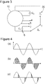
- Fig. 4(a) shows a sinus wave of a power supply waveform, more specifically of a input voltage being equal to output voltage when the triac is disabled.
- the power supply waveform is "regular” or “uncut”. If a motor is supplied with power having such a input voltage waveform, it spins at a speed corresponding to the winding design.
- Fig. 4(b) and (c) show the output voltage when the triac is enabled, wherein the triac cuts the power supply waveform, thus limiting the rotational speed of the motor.
- the magnitude of the speed reduction is directly depending on the way the phase-cut is implemented.
- Fig. 1 illustrates a schematic circuit diagram of motor and motor control related components of an exemplary exhaust device.
- An electric motor 10 as shown in Fig. 3 comprises a first winding W 1 , wherein the connection of the first winding W 1 with the power supply results in the maximum rotational speed of the electric motor 10.
- the first winding W 1 is connectable or connected in parallel with a plurality of windings W 2 , W 3 , W 4 , W 5 and a capacitor C 2 , also referred to as second capacitor C 2 .
- a main switch S 1 may be open or close in order to connect or disconnect the windings W 1 , W 2 , W 3 , W 4 , W 5 with the power supply 20.
- switch taps 1, 2, 3, 4, 5, 6 and 7 which allow various connective configurations of the windings W 1 , W 2 , W 3 , W 4 , W 5 and the capacitor C 2 .
- the capacitor C 2 is used in a single phase motor to create a phase shift in the currents through the different motor windings in order to a generate a rotating magnetic field that triggers the start of the rotation of the electric motor 10 from standstill.
- the first winding W 1 may be connected in parallel to a serial connection of the second winding W 2 and the capacitor C 2 .
- Third to fifth winding W 3 , W 4 , W 5 may be made inactive by a short cut between switch taps 4, 5, 6 and 7.
- the main switch S 1 may be closed, supplying an electric current, that is divided according to the parallel circuit configuration such that respective parts of the electric current flow through the first and second winding W 1 , W 2 , wherein the capacitor C 2 delays the part of the current through the second winding W 2 relative to that part of the current through the first winding W 1 and thus causes first and second windings W 1 , W 2 to induce a rotating magnetic field for starting the electric motor 10.
- Fig. 2 illustrates a schematic circuit diagram of motor and motor control related components of an exhaust device being modified in comparison to the embodiment shown in Fig. 1 , wherein the fifth winding W 5 has been removed, while an additional capacitor C 1 , in the following referred to as first capacitor C 1 , has been added.
- the first capacitor C 1 may be connectable or connected in series to the first winding W 1 , wherein the complete parallel branch comprising the second capacitor C 2 , and windings W 2 , W 3 , W 4 may be short cut or to a parallel connection of the first winding W 1 with a serial connection of the second capacitor C 2 with second and/or third and/or fourth winding W 2 , W 3 , W 4 . Or to a serial connection of the second and/or third and/or fourth winding W 2 , W 3 , W 4 .
- the first capacitor C 1 when switched in series with the first winding W 1 causes an increased voltage drop over the first winding W 1 compared to a voltage drop over the first winding W 1 with the first capacitor C 1 being not switched in series with the first winding W 1 .
- the rotational speed of the electric motor 10 is controlled at a very low magnitude such that the exhaust device can operated with a noise emission close at or below the threshold for audibility by a human.
- Fig. 3 illustrates a circuit diagram corresponding to the circuit diagram of Fig. 2 , illustrating switching possibilities provided by an additional second switch S 2 .
- the second switch S 2 allows to selectively connect the switch tap 1 as shown Fig. 2 with the switch taps 4, 5, 6 or 7.
- the first capacitor C 1 is connected in series with the first winding W 1 , thus, running the electric motor 10 at a very low rotational speed with low noise emission.
- the second switch S 2 is in a position connecting switch taps 1 and 6, the first capacitor C 1 is inactive and the voltage drop over the first winding W 1 causes the electric motor 10 to rotate at maximum rotational speed.
- the second switch S 2 is in a position connecting switch taps 1 and 4 or 1 and 5, the first winding W 1 is connected in series with the third and/or fourth winding W 3 , W 4 , resulting in a reduced rotational speed of the electric motor 10 having a noise emission beyond the audiable threshold.
Landscapes
- Engineering & Computer Science (AREA)
- Power Engineering (AREA)
- Control Of Ac Motors In General (AREA)
Abstract
Description
- The present invention relates to a kitchen appliance comprising an exhaust device for exhausting vapour or fumes generated in a cooking process.
-
DE 31 04 658 A1 discloses circuit arrangement for controlling the rotational speed of electric motors, in particular fan motors in kitchen hoods, by cutting the phase of the electric alternating current supplied to the motor. Those electric motors shall have a very low operating noise. However, it is known that electric motors operated by phase cutting control may emit a disturbing humming sound. In order to reduce such a humming sound in the aforementioned electric motors, a circuit arrangement having a triac-controlled phase cutting control is suggested, wherein an ohmic power resistor and a capacitor are arranged in series with the motor windings and parallel to the triac control arrangement and to an inductive element arranged in series to the triac control arrangement. Further, generation of a disturbing humming sound can be reduced. -
DE 32 07 262 A1 discloses a control for a rotational speed of a fan motor for a kitchen hood which shall result in the reduction of motor noise. The proposed control includes providing a sinus wave form for controlling the motor. - It is an object of the present invention to provide an advantageous kitchen appliance comprising an exhaust device having low noise generation.
- The object of the present invention is achieved by a kitchen appliance comprising an exhaust device for exhausting vapour or fumes generated in a cooking process, wherein the exhaust device comprises an electric motor and circuitry to control the rotational speed of the electric motor, wherein the electric motor comprises at least one first winding connectable or connected to a power source, wherein the first winding when being connected to the power source receives an alternating current provided by the power source and causes the electric motor to rotate at a predetermined rotational speed being dependent on the alternating current received by the first winding, wherein the circuitry comprises at least one first capacitor that is switchable or switched in series with the first winding and that causes the electric motor to rotate at a rotational speed lower than the predetermined rotational speed when being switched in series with the first winding.
- In this way, the use of a phase cutting control, specifically of a triac-controlled phase cutting control can be avoided. Thus, the electric motor of the exhaust device is enabled to run at a very low rotational speed such that the noise emission can advantageously fall below a threshold for audibility by a human. This allows to continue operation of the exhaust device even after a cooking process in a very quiet environment without hearable disturbances. Thus, the kitchen appliance can be operated at a noise level hardly or not hearable to the user after the end of the cooking process for completely removing residues of vapour or fumes still present at the end of the cooking process. It shall be noted that the suggested circuitry does not allow to control the rotational speed of the electric motor at more than two distinct speeds.
- Advantageously, the first capacitor switched in series with the first winding causes an increased voltage drop over the first winding compared to a voltage drop over the first winding with the first capacitor being not switched in series with the first winding.
- The voltage drop over the first winding causes a reduction of the rotational speed of the electric motor without cutting away a part of the voltage wave form. This results in an improved energy efficiency in comparison to a phase cutting control.
- Further advantageously, the electric motor includes at least two or three or four or more windings, wherein the electric motor is caused to rotate at its maximum rotational speed when the first winding, in particular is the only winding of the electric motor that, is connected to the power source.
- Thus, the electric motor can be adapted to a specific application of an exhaust device.
- According to a further advantageous embodiment, the electric motor is an asynchronous induction motor, in particular a single phase asynchronous induction motor, wherein the circuitry comprises at least one second capacitor that causes the electric motor to start rotation in response to connecting the electric motor with the power source, in particular that the at least one second capacitor causes a shift between a phase of a current in the first winding and a phase of a current in at least one second winding or in more than one further windings, such that the electric motor is caused to start rotation.
- Thus, a simple and efficient way is provided to start the electric motor of the exhaust device. The capacitor allows to create a phase shift between the windings in order to generate a rotating magnetic field for triggering rotation of the motor from standstill.
- In another advantageous embodiment of the invention, at least the second capacitor and the second winding and a third winding, in particular also a fourth winding, preferably also a fifth winding, are connectable or connected in series, wherein the serial connection of second capacitor, second and third winding, in particular also of fourth winding, preferably also of fifth winding, is connectable or connected in parallel with the first winding.
- The phase shift can be created between the first winding and the serial connection of second to fifth winding which allows reliable triggering of the motor start.
- In a further advantageous embodiment, the first capacitor has a capacitance in the range from 1µF to 11µF, in particular from 3µF to 9µF, preferably from 4µF to 8µF, more preferably 6µF, and/or
wherein the second capacitor has a capacitance in the range from 0,1µF to 10µF, in particular from 1µF to 6µF, preferably from 2µF to 4µF, more preferably 3,15µF. - Those ranges for the first capacitor have been found to achieve sufficient voltage drop over the first winding of a conventional electric motor commonly used for an exhaust device. The ranges for the second capacitor have been found to be appropriate for a suitable phase shift in the motor windings.
- In an advantageous embodiment, the first capacitor and the second capacitor are arranged in one common capacitor component housing.
- The use of such an integrated capacitor component simplifies the assembling process and increases robustness and safety of the circuitry used for the kitchen appliance.
- Further advantageously, the kitchen appliance is configured to operate the exhaust device when a cooking process associated with the kitchen appliance is running and/or is stopped, wherein the first capacitor is automatically switched in series with the first winding upon or after stopping of the cooking process associated with the kitchen appliance.
- If the kitchen appliance is a kitchen hood or an exhaust hood being arranged separately from the cooking appliance, e.g. the cooking hob, from which vapour or fumes are supposed to be exhausted, the kitchen hood or the exhaust hood may be configured to be in communication, e.g. in data communication, with the cooking appliance such that the kitchen hood or the exhaust hood may be operated, in particular automatically, when the cooking process runs on the cooking appliance. In this case, the cooking process is associated with the kitchen hood or the exhaust hood.
- Accordingly, if the cooking process is terminated or is stopped, the first capacitor is automatically switched in series with the first winding upon or after termination or stopping of the cooking process associated with the kitchen hood or the exhaust hood. Thus, the kitchen hood or exhaust hood can continue its operation automatically at a noise level hardly or not hearable to the user after the cooking process for completely removing residues of vapour or fumes still present at the end of the cooking process. It is further possible to foresee automatic termination of the operation of the kitchen hood or the exhaust hood after a fixed or otherwise defined period.
- Alternatively, if the exhaust device is integrated in a cooking appliance, it is possible that the exhaust device is controlled by or via the control means of the cooking appliance. In this case, the cooking process or processes running of the cooking appliance are associated with the cooking appliance, since these processes are subject to the cooking appliance control means.
- According to a further advantageous embodiment, the exhaust device generates an exhaust air flow volume equal or lower than 300m3 gas per hour, in particular equal or lower than 250m3 gas per hour, preferably equal or lower than 200m3 gas per hour.
- Those exhaust air flow volumes have been found to generate air flow noise hardly or not hearable for the user, while those volumes have been found to be sufficient for satisfactory cleaning of the ambient air in standard kitchens spaces.
- Further advantageously, the kitchen appliance may be a kitchen hood or an exhaust hood or a cooking appliance, in particular a cooking hob or an oven.
- Kitchen hoods or exhaust hoods are, in general, arranged above the cooking zones of cooking hobs in order to exhaust vapour or fumes by generated on that cooking zones.
- Alternatively, it is possible, that the exhaust device is integrated in a cooking appliance, e.g. a cooking hob or an oven. If the exhaust device is integrated in a cooking hob, an inlet may be provided on the cooking hob, e.g. in a cooking hob plate for sucking in vapour or fumes from the cooking zones into the cooking hob. If the exhaust device is integrated in an oven, it is not used to clean the ambient air in the kitchen space, but to exhaust vapour or fumes from a cooking chamber to a filter and/or to the outside of the oven.
- Novel and inventive features of the present invention are set forth in the appended claims.
- The present invention will be described in further detail with reference to the drawings, in which
- Fig. 1
- illustrates a schematic circuit diagram of a motor and motor control related components of an exemplary exhaust device;
- Fig. 2
- illustrates a schematic circuit diagram of a motor and motor control related components of an exhaust device according to an embodiment of the invention;
- Fig. 3
- illustrates another schematic circuit diagram a motor and motor control of an exhaust device according to an embodiment of the invention;
- Fig. 4
- illustrates diagrams explaining the effect of a phase cutting control on an alternating electric current according to the prior art.
- The following description is set out with respect to kitchen hoods or exhaust hoods being separate from a cooking appliance. Nevertheless, all features disclosed in the following description can also be applied in isolation or in arbitrary combination to an exhaust device being integrated into a cooking appliance such as a cooking hob or an oven, unless stated otherwise.
- Kitchen hoods or exhaust hoods are, in general, equipped with a ventilation unit having a fan that allows the evacuation of vapours, fumes, odors and smells from the kitchen environment, thanks to the air flow elaborated by the fan itself. The fan us usually driven by an electric motor, wherein the rotational speed of the electric motor correlates to the magnitude of air flow or the air flow volume conveyed by the fan.
- It is a common practice to keep ON the hood during the cooking process.
- Additionally, it is possible to continue operation of the kitchen hood or the exhaust hood also after the termination of the cooking process in order to get a complete cleaning of the ambient air within the kitchen space. Cleaning the ambient air in the kitchen space after cooking process can be obtained with air flow rates lower than those used during the cooking process.
- Lower air flow rates result in a lower noise emission of the kitchen hood or the exhaust hood. A low noise emission, preferably below the threshold for human audibility, is a required for a comfortable kitchen environment.
- It is advantageous to provide a kitchen hood with an exhaust hood with a dedicated fan speed or a dedicated fan speed function to provide an air flow that is sufficient to remove residual vapour or fumes, odors or smells, while keeping low the noise level. Accordingly, a kitchen hood or exhaust hood is achieved with a specific operation mode in which the user does not or at least does hardly not percept the operation of the kitchen hood, thanks to low air flow rate.
- The noise produced by the hood operating in such a specific operation mode does not derive from the air flow, because it is set at a value or order of magnitude that has been found to be sufficient to properly clean the ambient air in the kitchen space.
- However, as a further source of noise, induction motors which are commonly used in kitchen hoods or exhaust hoods, typically generate a background "buzz" or "humming" motor sound. Such a motor sound is typical for this kind of motors, and it is masked, i.e. not hearable, only by the noise resulting from the air flow when the kitchen hood or exhaust hood is operated at mid / high air flow rates.
- It is also known to use brushless DC electric motors or electronically commutated motors or synchronous DC motors for kitchen hoods or exhaust hoods. The motor sound of a brushless DC electric motor used in a kitchen hood or an exhaust hood is negligible and not hearable by a user. However brushless DC electric motors are expensive.
- It is further known to use induction motors or asynchronous induction motors in kitchen hoods or exhaust hoods. It is known to use a dedicated triac acting on the asynchronous induction motors to realise control of the rotational speed of the motor. A triac is an electronic device able to implement a phase-cut of the waveform of the motor power supply, producing a lower rotational speed of the motor (lower air flow rate of the fan).
-
Fig. 4(a) shows a sinus wave of a power supply waveform, more specifically of a input voltage being equal to output voltage when the triac is disabled. The power supply waveform is "regular" or "uncut". If a motor is supplied with power having such a input voltage waveform, it spins at a speed corresponding to the winding design. -
Fig. 4(b) and (c) show the output voltage when the triac is enabled, wherein the triac cuts the power supply waveform, thus limiting the rotational speed of the motor. The magnitude of the speed reduction is directly depending on the way the phase-cut is implemented. - The control of the rotational speed by phase cutting result in the typical background "buzz" or "humming" motor sound.
-
Fig. 1 illustrates a schematic circuit diagram of motor and motor control related components of an exemplary exhaust device. Anelectric motor 10 as shown inFig. 3 comprises a first winding W1, wherein the connection of the first winding W1 with the power supply results in the maximum rotational speed of theelectric motor 10. The first winding W1 is connectable or connected in parallel with a plurality of windings W2, W3, W4, W5 and a capacitor C2, also referred to as second capacitor C2. A main switch S1 may be open or close in order to connect or disconnect the windings W1, W2, W3, W4, W5 with thepower supply 20. - In order to provide circuit configuration for starting the
motor 10 or for varying the rotational speed of theelectric motor 10, there are switch taps 1, 2, 3, 4, 5, 6 and 7 which allow various connective configurations of the windings W1, W2, W3, W4, W5 and the capacitor C2. - The capacitor C2 is used in a single phase motor to create a phase shift in the currents through the different motor windings in order to a generate a rotating magnetic field that triggers the start of the rotation of the
electric motor 10 from standstill. E.g. in order to provide a suitable circuit configuration for starting the motor from standstill, the first winding W1 may be connected in parallel to a serial connection of the second winding W2 and the capacitor C2. Third to fifth winding W3, W4, W5 may be made inactive by a short cut between switch taps 4, 5, 6 and 7. - In such a configuration, the main switch S1 may be closed, supplying an electric current, that is divided according to the parallel circuit configuration such that respective parts of the electric current flow through the first and second winding W1, W2, wherein the capacitor C2 delays the part of the current through the second winding W2 relative to that part of the current through the first winding W1 and thus causes first and second windings W1, W2 to induce a rotating magnetic field for starting the
electric motor 10. -
Fig. 2 illustrates a schematic circuit diagram of motor and motor control related components of an exhaust device being modified in comparison to the embodiment shown inFig. 1 , wherein the fifth winding W5 has been removed, while an additional capacitor C1, in the following referred to as first capacitor C1, has been added. - The first capacitor C1 may be connectable or connected in series to the first winding W1, wherein the complete parallel branch comprising the second capacitor C2, and windings W2, W3, W4 may be short cut or to a parallel connection of the first winding W1 with a serial connection of the second capacitor C2 with second and/or third and/or fourth winding W2, W3, W4. Or to a serial connection of the second and/or third and/or fourth winding W2, W3, W4.
- The first capacitor C1 when switched in series with the first winding W1 causes an increased voltage drop over the first winding W1 compared to a voltage drop over the first winding W1 with the first capacitor C1 being not switched in series with the first winding W1.
- Thus, the rotational speed of the
electric motor 10 is controlled at a very low magnitude such that the exhaust device can operated with a noise emission close at or below the threshold for audibility by a human. -
Fig. 3 illustrates a circuit diagram corresponding to the circuit diagram ofFig. 2 , illustrating switching possibilities provided by an additional second switch S2. The second switch S2 allows to selectively connect theswitch tap 1 as shownFig. 2 with the switch taps 4, 5, 6 or 7. In a position of second switch S2 connecting switch taps 1 and 7, the first capacitor C1 is connected in series with the first winding W1, thus, running theelectric motor 10 at a very low rotational speed with low noise emission. - If the second switch S2 is in a position connecting switch taps 1 and 6, the first capacitor C1 is inactive and the voltage drop over the first winding W1 causes the
electric motor 10 to rotate at maximum rotational speed. - If the second switch S2 is in a position connecting switch taps 1 and 4 or 1 and 5, the first winding W1 is connected in series with the third and/or fourth winding W3, W4, resulting in a reduced rotational speed of the
electric motor 10 having a noise emission beyond the audiable threshold. -
- 1 to 7
- taps
- 10
- electric motor
- 20
- power supply
- S1
- Main switch
- W1 to W5
- Windings
- C1 to C2
- Capacitors
Claims (10)
- Kitchen appliance comprising an exhaust device for exhausting vapour or fumes generated in a cooking process, wherein the exhaust device comprises an electric motor (10) and circuitry to control the rotational speed of the electric motor (10), wherein the electric motor (10) comprises at least one first winding (W1) connectable or connected to a power source, wherein the first winding (W1) when being connected to the power source (20) receives an alternating current provided by the power source (20) and causes the electric motor (10) to rotate at a predetermined rotational speed being dependent on the alternating current received by the first winding (W1), wherein the circuitry comprises at least one first capacitor (C1) that is switchable or switched in series with the first winding (W1) and that causes the electric motor (10) to rotate at a rotational speed lower than the predetermined rotational speed when being switched in series with the first winding (W1).
- Kitchen appliance according to claim 1, characterized in that the first capacitor (C1) switched in series with the first winding (W1) causes an increased voltage drop over the first winding (W1) compared to a voltage drop over the first winding (W1) with the first capacitor (C1) being not switched in series with the first winding (W1).
- Kitchen appliance according to any one of the preceding claims, characterized in that the electric motor (10) includes at least two or three or four or more windings (W1, W2, W3, W4, W5), wherein the electric motor (10) is caused to rotate at its maximum rotational speed when the first winding (W1), in particular is the only winding of the electric motor (10) that, is connected to the power source (20).
- Kitchen appliance according to any of the preceding claims, characterized in that the electric motor (10) is an asynchronous induction motor, in particular a single phase asynchronous induction motor, wherein the circuitry comprises at least one second capacitor (C2) that causes the electric motor (10) to start rotation in response to connecting the electric motor (10) with the power source (20), in particular that the at least one second capacitor (C2) causes a shift between a phase of a current in the first winding (W1) and a phase of a current in at least one second winding (W2) or in more than one further windings (W3, W4, W5), such that the electric motor (10) is caused to start rotation.
- Kitchen appliance according to claim 4, characterized in that at least the second capacitor (C2) and the second winding (W2) and a third winding (W3), in particular also a fourth winding (W4), preferably also a fifth winding (W5), are connectable or connected in series, wherein the serial connection of second capacitor (C2), second and third winding (W2, W3), in particular also of fourth winding (W4), preferably also of fifth winding (W5), is connectable or connected in parallel with the first winding (W1).
- Kitchen appliance according to any one of the preceding claims, characterized in that the first capacitor (C1) has a capacitance in the range from 1µF to 11µF, in particular from 3µF to 9µF, preferably from 4µF to 8µF, more preferably 6µF,
and/or
wherein the second capacitor (C2) has a capacitance in the range from 0,1µF to 10µF, in particular from 1µF to 6µF, preferably from 2µF to 4µF, more preferably 3,15µF. - Kitchen appliance according to any one of the preceding claims, characterized in that the first capacitor (C1) and the second capacitor (C2) are arranged in one common capacitor component housing.
- Kitchen appliance according to any one of the preceding claims, characterized in that the kitchen appliance is configured to operate the exhaust device when a cooking process associated with the kitchen appliance is running and/or is stopped, wherein the first capacitor (C1) is automatically switched in series with the first winding (W1) upon or after stopping of the cooking process associated with the kitchen appliance.
- Kitchen appliance according to any one of the preceding claims, characterized in that the exhaust device generates an exhaust air flow volume equal or lower than 300m3 gas per hour, in particular equal or lower than 250m3 gas per hour, preferably equal or lower than 200m3 gas per hour.
- Kitchen appliance according to any one of the preceding claims, characterized in that the kitchen appliance is a kitchen hood or an exhaust hood or a cooking appliance, in particular a cooking hob or an oven.
Priority Applications (1)
| Application Number | Priority Date | Filing Date | Title |
|---|---|---|---|
| EP21179397.1A EP4106184A1 (en) | 2021-06-15 | 2021-06-15 | Kitchen appliance comprising an exhaust device |
Applications Claiming Priority (1)
| Application Number | Priority Date | Filing Date | Title |
|---|---|---|---|
| EP21179397.1A EP4106184A1 (en) | 2021-06-15 | 2021-06-15 | Kitchen appliance comprising an exhaust device |
Publications (1)
| Publication Number | Publication Date |
|---|---|
| EP4106184A1 true EP4106184A1 (en) | 2022-12-21 |
Family
ID=76483040
Family Applications (1)
| Application Number | Title | Priority Date | Filing Date |
|---|---|---|---|
| EP21179397.1A Pending EP4106184A1 (en) | 2021-06-15 | 2021-06-15 | Kitchen appliance comprising an exhaust device |
Country Status (1)
| Country | Link |
|---|---|
| EP (1) | EP4106184A1 (en) |
Cited By (1)
| Publication number | Priority date | Publication date | Assignee | Title |
|---|---|---|---|---|
| CN119983340A (en) * | 2025-01-24 | 2025-05-13 | 华帝股份有限公司 | A range hood gear adjustment method |
Citations (5)
| Publication number | Priority date | Publication date | Assignee | Title |
|---|---|---|---|---|
| DE3104658A1 (en) | 1981-02-10 | 1982-08-19 | Bosch-Siemens Hausgeräte GmbH, 7000 Stuttgart | Circuit arrangement for controlling the rotation speed of electric motors |
| DE3207262A1 (en) | 1982-03-01 | 1983-09-08 | Robert Seuffer GmbH & Co, 7260 Calw | Speed control circuit for a ventilator motor, especially in a vapour hood |
| US6208113B1 (en) * | 1998-09-21 | 2001-03-27 | Ebm Werke Gmbh & Co. | System for controlling the rotation of AC motors |
| CN203744333U (en) * | 2013-12-16 | 2014-07-30 | 王誉燕 | Motor speed adjusting device for air capacity control of extractor hood |
| CN206060490U (en) * | 2016-10-10 | 2017-03-29 | 常州朗奇威电器有限公司 | Three velocity modulation speed motors |
-
2021
- 2021-06-15 EP EP21179397.1A patent/EP4106184A1/en active Pending
Patent Citations (5)
| Publication number | Priority date | Publication date | Assignee | Title |
|---|---|---|---|---|
| DE3104658A1 (en) | 1981-02-10 | 1982-08-19 | Bosch-Siemens Hausgeräte GmbH, 7000 Stuttgart | Circuit arrangement for controlling the rotation speed of electric motors |
| DE3207262A1 (en) | 1982-03-01 | 1983-09-08 | Robert Seuffer GmbH & Co, 7260 Calw | Speed control circuit for a ventilator motor, especially in a vapour hood |
| US6208113B1 (en) * | 1998-09-21 | 2001-03-27 | Ebm Werke Gmbh & Co. | System for controlling the rotation of AC motors |
| CN203744333U (en) * | 2013-12-16 | 2014-07-30 | 王誉燕 | Motor speed adjusting device for air capacity control of extractor hood |
| CN206060490U (en) * | 2016-10-10 | 2017-03-29 | 常州朗奇威电器有限公司 | Three velocity modulation speed motors |
Cited By (1)
| Publication number | Priority date | Publication date | Assignee | Title |
|---|---|---|---|---|
| CN119983340A (en) * | 2025-01-24 | 2025-05-13 | 华帝股份有限公司 | A range hood gear adjustment method |
Similar Documents
| Publication | Publication Date | Title |
|---|---|---|
| KR101260086B1 (en) | Method and arrangement for supplying power to several induction coils in an induction apparatus | |
| CA2155810C (en) | Apparatus and method for starting and controlling a motor | |
| US6208113B1 (en) | System for controlling the rotation of AC motors | |
| CN1224802C (en) | Combined household utensil, its control and mounting method | |
| WO2011034859A2 (en) | Full cycle ac power control | |
| US20230258340A1 (en) | Cooking hob with extractor hood | |
| IT1292485B1 (en) | VENTILATION SYSTEM FOR ELECTRIC FOOD COOKING APPLIANCES INCLUDING A HOB AND AN OVEN | |
| CN100380052C (en) | Wall-mounted microwave oven and method for controlling its hood motor | |
| EP1070920A1 (en) | Suction unit for a cooker hood | |
| KR930018166A (en) | Rotor interference elimination method of single phase induction motor and single phase induction motor centrifugal pump unit | |
| US5994684A (en) | Surge current prevention circuit of microwave oven | |
| JP7190333B2 (en) | MOTOR DRIVE CONTROL DEVICE, ELECTRONIC DEVICE, AND MOTOR CONTROL METHOD | |
| CN1245592C (en) | Combination device of hood and microwave oven | |
| JP4251161B2 (en) | Induction heating cooker | |
| KR100239166B1 (en) | Controller for motor in vacuum cleaner | |
| EP0981266B1 (en) | Microwave oven, its management of the starting current | |
| US5623400A (en) | Control system for smoke exhauster | |
| CN121274269A (en) | Kitchen exhaust system | |
| JP2000166286A (en) | Fan motor and electric equipment using the same | |
| KR100231050B1 (en) | Inrush current prevention circuit for microwave oven | |
| KR200235647Y1 (en) | Circuit for driving vent motor of Over The Range | |
| CN1705411A (en) | Impulse current prevented circuit of microwave oven | |
| KR100953636B1 (en) | Inrush Current Prevention Circuit of Microwave Oven | |
| JP2864872B2 (en) | High frequency heating equipment | |
| WO2016042470A1 (en) | Motor for a suction assembly of an enhanced-performance extractor hood |
Legal Events
| Date | Code | Title | Description |
|---|---|---|---|
| PUAI | Public reference made under article 153(3) epc to a published international application that has entered the european phase |
Free format text: ORIGINAL CODE: 0009012 |
|
| STAA | Information on the status of an ep patent application or granted ep patent |
Free format text: STATUS: THE APPLICATION HAS BEEN PUBLISHED |
|
| AK | Designated contracting states |
Kind code of ref document: A1 Designated state(s): AL AT BE BG CH CY CZ DE DK EE ES FI FR GB GR HR HU IE IS IT LI LT LU LV MC MK MT NL NO PL PT RO RS SE SI SK SM TR |
|
| STAA | Information on the status of an ep patent application or granted ep patent |
Free format text: STATUS: REQUEST FOR EXAMINATION WAS MADE |
|
| 17P | Request for examination filed |
Effective date: 20230621 |
|
| RBV | Designated contracting states (corrected) |
Designated state(s): AL AT BE BG CH CY CZ DE DK EE ES FI FR GB GR HR HU IE IS IT LI LT LU LV MC MK MT NL NO PL PT RO RS SE SI SK SM TR |
|
| STAA | Information on the status of an ep patent application or granted ep patent |
Free format text: STATUS: EXAMINATION IS IN PROGRESS |
|
| 17Q | First examination report despatched |
Effective date: 20241127 |