EP4106177A1 - Friction power generation device based on friction brake, and friction brake - Google Patents
Friction power generation device based on friction brake, and friction brake Download PDFInfo
- Publication number
- EP4106177A1 EP4106177A1 EP21825198.1A EP21825198A EP4106177A1 EP 4106177 A1 EP4106177 A1 EP 4106177A1 EP 21825198 A EP21825198 A EP 21825198A EP 4106177 A1 EP4106177 A1 EP 4106177A1
- Authority
- EP
- European Patent Office
- Prior art keywords
- comb
- sensing electrode
- friction
- electrode
- shaped
- Prior art date
- Legal status (The legal status is an assumption and is not a legal conclusion. Google has not performed a legal analysis and makes no representation as to the accuracy of the status listed.)
- Pending
Links
Images






Classifications
-
- F—MECHANICAL ENGINEERING; LIGHTING; HEATING; WEAPONS; BLASTING
- F16—ENGINEERING ELEMENTS AND UNITS; GENERAL MEASURES FOR PRODUCING AND MAINTAINING EFFECTIVE FUNCTIONING OF MACHINES OR INSTALLATIONS; THERMAL INSULATION IN GENERAL
- F16D—COUPLINGS FOR TRANSMITTING ROTATION; CLUTCHES; BRAKES
- F16D61/00—Brakes with means for making the energy absorbed available for use
-
- F—MECHANICAL ENGINEERING; LIGHTING; HEATING; WEAPONS; BLASTING
- F16—ENGINEERING ELEMENTS AND UNITS; GENERAL MEASURES FOR PRODUCING AND MAINTAINING EFFECTIVE FUNCTIONING OF MACHINES OR INSTALLATIONS; THERMAL INSULATION IN GENERAL
- F16D—COUPLINGS FOR TRANSMITTING ROTATION; CLUTCHES; BRAKES
- F16D65/00—Parts or details
- F16D65/02—Braking members; Mounting thereof
-
- F—MECHANICAL ENGINEERING; LIGHTING; HEATING; WEAPONS; BLASTING
- F16—ENGINEERING ELEMENTS AND UNITS; GENERAL MEASURES FOR PRODUCING AND MAINTAINING EFFECTIVE FUNCTIONING OF MACHINES OR INSTALLATIONS; THERMAL INSULATION IN GENERAL
- F16D—COUPLINGS FOR TRANSMITTING ROTATION; CLUTCHES; BRAKES
- F16D65/00—Parts or details
- F16D65/14—Actuating mechanisms for brakes; Means for initiating operation at a predetermined position
- F16D65/16—Actuating mechanisms for brakes; Means for initiating operation at a predetermined position arranged in or on the brake
- F16D65/18—Actuating mechanisms for brakes; Means for initiating operation at a predetermined position arranged in or on the brake adapted for drawing members together, e.g. for disc brakes
-
- F—MECHANICAL ENGINEERING; LIGHTING; HEATING; WEAPONS; BLASTING
- F16—ENGINEERING ELEMENTS AND UNITS; GENERAL MEASURES FOR PRODUCING AND MAINTAINING EFFECTIVE FUNCTIONING OF MACHINES OR INSTALLATIONS; THERMAL INSULATION IN GENERAL
- F16D—COUPLINGS FOR TRANSMITTING ROTATION; CLUTCHES; BRAKES
- F16D65/00—Parts or details
- F16D65/02—Braking members; Mounting thereof
- F16D65/04—Bands, shoes or pads; Pivots or supporting members therefor
- F16D65/08—Bands, shoes or pads; Pivots or supporting members therefor for internally-engaging brakes
-
- F—MECHANICAL ENGINEERING; LIGHTING; HEATING; WEAPONS; BLASTING
- F16—ENGINEERING ELEMENTS AND UNITS; GENERAL MEASURES FOR PRODUCING AND MAINTAINING EFFECTIVE FUNCTIONING OF MACHINES OR INSTALLATIONS; THERMAL INSULATION IN GENERAL
- F16D—COUPLINGS FOR TRANSMITTING ROTATION; CLUTCHES; BRAKES
- F16D65/00—Parts or details
- F16D65/02—Braking members; Mounting thereof
- F16D65/04—Bands, shoes or pads; Pivots or supporting members therefor
- F16D65/092—Bands, shoes or pads; Pivots or supporting members therefor for axially-engaging brakes, e.g. disc brakes
-
- F—MECHANICAL ENGINEERING; LIGHTING; HEATING; WEAPONS; BLASTING
- F16—ENGINEERING ELEMENTS AND UNITS; GENERAL MEASURES FOR PRODUCING AND MAINTAINING EFFECTIVE FUNCTIONING OF MACHINES OR INSTALLATIONS; THERMAL INSULATION IN GENERAL
- F16D—COUPLINGS FOR TRANSMITTING ROTATION; CLUTCHES; BRAKES
- F16D65/00—Parts or details
- F16D65/02—Braking members; Mounting thereof
- F16D65/10—Drums for externally- or internally-engaging brakes
-
- F—MECHANICAL ENGINEERING; LIGHTING; HEATING; WEAPONS; BLASTING
- F16—ENGINEERING ELEMENTS AND UNITS; GENERAL MEASURES FOR PRODUCING AND MAINTAINING EFFECTIVE FUNCTIONING OF MACHINES OR INSTALLATIONS; THERMAL INSULATION IN GENERAL
- F16D—COUPLINGS FOR TRANSMITTING ROTATION; CLUTCHES; BRAKES
- F16D65/00—Parts or details
- F16D65/02—Braking members; Mounting thereof
- F16D65/12—Discs; Drums for disc brakes
- F16D65/127—Discs; Drums for disc brakes characterised by properties of the disc surface; Discs lined with friction material
-
- F—MECHANICAL ENGINEERING; LIGHTING; HEATING; WEAPONS; BLASTING
- F16—ENGINEERING ELEMENTS AND UNITS; GENERAL MEASURES FOR PRODUCING AND MAINTAINING EFFECTIVE FUNCTIONING OF MACHINES OR INSTALLATIONS; THERMAL INSULATION IN GENERAL
- F16D—COUPLINGS FOR TRANSMITTING ROTATION; CLUTCHES; BRAKES
- F16D65/00—Parts or details
- F16D65/14—Actuating mechanisms for brakes; Means for initiating operation at a predetermined position
- F16D65/16—Actuating mechanisms for brakes; Means for initiating operation at a predetermined position arranged in or on the brake
- F16D65/22—Actuating mechanisms for brakes; Means for initiating operation at a predetermined position arranged in or on the brake adapted for pressing members apart, e.g. for drum brakes
-
- F—MECHANICAL ENGINEERING; LIGHTING; HEATING; WEAPONS; BLASTING
- F16—ENGINEERING ELEMENTS AND UNITS; GENERAL MEASURES FOR PRODUCING AND MAINTAINING EFFECTIVE FUNCTIONING OF MACHINES OR INSTALLATIONS; THERMAL INSULATION IN GENERAL
- F16D—COUPLINGS FOR TRANSMITTING ROTATION; CLUTCHES; BRAKES
- F16D69/00—Friction linings; Attachment thereof; Selection of coacting friction substances or surfaces
-
- H—ELECTRICITY
- H02—GENERATION; CONVERSION OR DISTRIBUTION OF ELECTRIC POWER
- H02N—ELECTRIC MACHINES NOT OTHERWISE PROVIDED FOR
- H02N1/00—Electrostatic generators or motors using a solid moving electrostatic charge carrier
- H02N1/04—Friction generators
-
- F—MECHANICAL ENGINEERING; LIGHTING; HEATING; WEAPONS; BLASTING
- F16—ENGINEERING ELEMENTS AND UNITS; GENERAL MEASURES FOR PRODUCING AND MAINTAINING EFFECTIVE FUNCTIONING OF MACHINES OR INSTALLATIONS; THERMAL INSULATION IN GENERAL
- F16D—COUPLINGS FOR TRANSMITTING ROTATION; CLUTCHES; BRAKES
- F16D2121/00—Type of actuator operation force
- F16D2121/18—Electric or magnetic
Definitions
- This application relates to the field of triboelectric generation technologies, and more specifically, to a triboelectric generation technology based on a friction brake.
- a braking process is a process to decelerate or stop a moving object, and widely exists in the fields of vehicle transportation, hoisting machinery, and construction machinery.
- the braking process may usually be implemented by using a brake.
- a friction brake may brake a moving object through frictional resistance, and has advantages of a simple structure and low cost.
- a large amount of energy is often consumed in the braking process, which is mainly dissipated in the form of frictional heat, resulting in waste of a large amount of energy.
- energy recovery solutions based on a braking process mainly include: (1) driving, through relative motion between brake components, an electromagnetic generator to rotate, thereby generating electric energy; (2) converting motion of an object into hydraulic potential energy in an hydraulic apparatus, to store energy; (3) using heat generated by friction between brake components to generate electricity with the help of thermoelectric reaction; (4) in new energy vehicles, directly reversing a motor to serve as a generator, and using a battery as a load to charge the battery, thereby decelerating while recovering energy; and (5) using a triboelectric nanogenerator to recover energy.
- a triboelectric generation apparatus based on a friction brake is provided according to an embodiment of this application.
- the friction brake includes a first friction component and a second friction component arranged to face each other, the first friction component is configured to generate a friction braking force and an electric charge when contact friction occurs between the first friction component and the second friction component.
- the triboelectric generation apparatus includes: a first sensing electrode and a second sensing electrode, and an electric charge collection circuit.
- the first sensing electrode and the second sensing electrode are arranged in the first friction component, when contact friction occurs between the first friction component and the second friction component, a first induced electric charge is generated on the first sensing electrode, and a second induced electric charge is generated on the second sensing electrode, the first induced electric charge is different from the second induced electric charge.
- the electric charge collection circuit is connected to the first sensing electrode and the second sensing electrode, and is configured to store the electric charges collected from the first sensing electrode and the second sensing electrode.
- a friction plate is arranged on an inner side of the second friction component, the inner side of the second friction component faces towards the first friction component, a friction material of the first friction component has a first electric polarity, and a friction material of the friction plate on the second friction component has a second electric polarity, the first electric polarity is opposite to the second electric polarity.
- the triboelectric generation apparatus further includes: a reed switch arranged in the second friction component, the electric charge collection circuit is further configured to store, under control of the reed switch, the electric charges collected from the first sensing electrode and the second sensing electrode.
- the triboelectric generation apparatus further includes: a first switch electrode and a second switch electrode that are arranged in the first friction component.
- the electric charge collection circuit includes: a rectifier circuit and an electric charge storage circuit. A first input terminal of the rectifier circuit is connected to the first sensing electrode, a second input terminal of the rectifier circuit is connected to the second sensing electrode, and a first output terminal of the rectifier circuit is connected to the first switch electrode. A first input terminal of electric charge storage circuit is connected to the second switch electrode, and a second input terminal of electric charge storage circuit is connected to a second output terminal of the rectifier circuit.
- the reed switch is configured to control a connection between the first switch electrode and the second switch electrode. In a case that the first switch electrode is connected to the second switch electrode by the reed switch, the electric charge storage circuit is configured to store the electric charges collected from the first sensing electrode and the second sensing electrode.
- the first friction component is in a shape of a disc ring
- the first sensing electrode is an annular outer comb-shaped sensing electrode
- the second sensing electrode is an annular inner comb-shaped sensing electrode
- comb teeth of the outer comb-shaped sensing electrode and comb teeth of the inner comb-shaped sensing electrode are meshed to each other, and a first gap is defined between the outer comb-shaped sensing electrode and the inner comb-shaped sensing electrode.
- the first switch electrode and the second switch electrode are arranged on an inner ring or an outer ring of the first friction component.
- the first switch electrode is an annular outer comb-shaped switch electrode
- the second switch electrode is an annular inner comb-shaped switch electrode; or the first switch electrode is the annular inner comb-shaped switch electrode, the second switch electrode is the annular outer comb-shaped switch electrode.
- a quantity of comb teeth of the outer comb-shaped switch electrode and a quantity of comb teeth of the inner comb-shaped switch electrode are both a first quantity, and the comb teeth of the outer comb-shaped switch electrode and the comb teeth of the inner comb-shaped switch electrode are arranged opposite to each other to form a first quantity of comb tooth pairs, and a second gap is defined between oppositely arranged comb teeth in each of the comb tooth pairs,
- the reed switch is configured to control a mechanical connection between the outer comb-shaped switch electrode and the inner comb-shaped switch electrode.
- a quantity of the comb teeth of the outer comb-shaped sensing electrode and a quantity of the comb teeth of the inner comb-shaped sensing electrode are both a second quantity, and the first quantity is two times the second quantity.
- the outer comb-shaped sensing electrode and the inner comb-shaped sensing electrode have a same comb tooth width and a same radial length, and the first quantity of comb tooth pairs have a one-to-one correspondence with the comb teeth of the outer comb-shaped sensing electrode and the comb teeth of the inner comb-shaped sensing electrode.
- the comb tooth pairs of the outer comb-shaped switch electrode and the inner comb-shaped switch electrode are respectively arranged on edges of the comb teeth of the outer comb-shaped sensing electrode and the comb teeth of the inner comb-shaped sensing electrode in a radial direction.
- the reed switch is arranged on an edge of the second friction component in a radial direction, and is arranged parallel to the second gap, a radial width of the reed switch is greater than a width of the second gap, to conduct the outer comb-shaped switch electrode with the inner comb-shaped switch electrode when the reed switch is in contact with the outer comb-shaped switch electrode and the inner comb-shaped switch electrode.
- the second friction component is an incomplete ring sheet
- a friction plate is arranged on an inner side of the second friction component, the inner side of the second friction component faces towards the first friction component
- the first friction component is configured to rotate around a center of the disc ring, to generate contact friction with the friction plate on the second friction component.
- a friction material of the first friction component has a first electric polarity
- a friction material of the friction plate on the second friction component has a second electric polarity, the first electric polarity is opposite to the second electric polarity.
- the friction plate includes multiple annular grid plates, each of the annular grid plates is radially arranged in an annular region corresponding to a region in which the comb teeth of the outer comb-shaped sensing electrode and the comb teeth of the inner comb-shaped sensing electrode are meshed to each other.
- Each of the annular grid plates has a same comb tooth shape as the comb teeth of the outer comb-shaped sensing electrode or the comb teeth of the inner comb-shaped sensing electrode.
- a third gap is defined between adjacent annular grid plates of the annular grid plates, the third gap has the same width as a gap between adjacent comb teeth of the outer comb-shaped sensing electrode or a gap between adjacent comb teeth of the inner comb-shaped sensing electrode.
- the first friction component is provided with an opening at a position corresponding to the first gap
- the second friction component is provided with an opening at a position corresponding to the third gap
- the outer comb-shaped sensing electrode and the inner comb-shaped sensing electrode are made of copper, nickel, gold, silver, aluminum, or iron.
- a friction brake is provided according to an embodiment of this application, which includes: a brake disc and a brake pad that are arranged to face each other.
- the brake disc is configured to generate a friction braking force and an electric charge when contact friction occurs between the brake disc and the brake pad.
- the brake further includes a triboelectric generation apparatus, the triboelectric generation apparatus includes: a first sensing electrode and a second sensing electrode, and an electric charge collection circuit.
- the first sensing electrode and the second sensing electrode are arranged in the brake disc, when contact friction occurs between the brake disc and the brake pad, a first induced electric charge is generated on the first sensing electrode, and a second induced electric charge is generated on the second sensing electrode, the first induced electric charge is different from the second induced electric charge.
- the electric charge collection circuit is connected to the first sensing electrode and the second sensing electrode, and is configured to store the electric charges collected from the first sensing electrode and the second sensing electrode.
- a friction plate is arranged on an inner side of the brake pad, the inner side of the brake pad faces towards the brake disc.
- a friction material of the brake disc has a first electric polarity
- a friction material of the friction plate on the brake pad has a second electric polarity, the first electric polarity is opposite to the second electric polarity.
- the friction brake is a disc brake
- the brake disc is in a shape of a disc ring
- the brake pad is an incomplete annular sheet
- the brake disc and the brake pad are coaxial
- the brake pad is arranged on one of or both sides of the brake disc.
- the friction brake is a drum brake
- the brake disc is an annular cylinder
- the brake pad is an incomplete annular cylinder
- the brake disc and the brake pad are coaxial
- the brake pad bis arranged on an inner side of the brake disc.
- a triboelectric generation apparatus based on a friction brake and a friction brake are provided according to the embodiments of this application.
- the triboelectric generation apparatus takes the structure of the friction brake into full consideration. In a case that contact friction occurs between a first friction component and a second friction component in the friction brake, a first induced electric charge is generated on a first sensing electrode, a second induced electric charge is generated on a second sensing electrode, and an electric charge collection circuit is connected to the first sensing electrode and the second sensing electrode, to store the electric charges collected from the first sensing electrode and the second sensing electrode, thereby implementing collection for triboelectric generation.
- the apparatus combines a triboelectric nanogenerator with a specific structure of the friction brake to a high extent, which simplifies the structure and improves the reliability.
- a synchronous electric charge extraction circuit is used to decouple the impedance of the triboelectric nanogenerator and a load circuit, thereby improving the performance of the circuit under different loads; and a ladder-shaped mechanical contact switch is integrated onto the brake, thereby improving the stability and precision of a circuit switch.
- a triboelectric nanogenerator generates a movement of an electric charge through frictional motion between different materials based on the principles of triboelectric charging and electrostatic induction, to collect and utilize the electric charge, which is a process of converting mechanical energy into electric energy.
- a synchronized electric charge extraction (SECE) circuit includes devices such as bridges, switches, and inductors, and when an output voltage of the generator is maximum, the switches are turned on synchronously to extract all electric charges.
- a brake is an apparatus with functions such as decelerating or stopping a moving object or maintaining a moving object in a stopped state.
- the brake usually achieves braking and deceleration through contact friction between a brake disc and a brake pad.
- a brake pad is one of the components in the brake.
- a component in the brake that has a relatively small contact surface and that comes into contact with the brake disc under the driving and control of the system to generate contact friction is referred to as a brake pad, for example, a brake pad in a drum brake of an automobile.
- a brake disc is another important component in the brake that has a relatively large contact surface and that usually moves with the moving object, for example, a brake drum in a drum brake of an automobile.
- a braking process is a process to decelerate or stop a moving object, and widely exists in the fields of vehicle transportation, hoisting machinery, and construction machinery.
- the braking process may usually be implemented by using a brake.
- a friction brake may brake a moving object through frictional resistance, and has advantages of a simple structure and low cost.
- energy consumed in a braking process accounts for about 27.5% of the total traction energy of the automobile under ECE-15 condition, while under the US EPA 75 Urban condition and the Japan 1015 condition that are closer to the urban traveling condition, proportions of energy consumed in a braking process reaches about 48.3% and 53% respectively.
- a friction drum or disc brake shown in FIG. 1
- energy consumed by braking is mainly dissipated in the form of frictional heat. If this kind of energy can be recovered and utilized, it will be beneficial to improve the battery life and energy efficiency of the automobile.
- the TENG may cause different materials to generate electric charges in a contact friction manner due to triboelectric charging, cause a directional movement of the electric charges through electrostatic induction, thereby converting mechanical energy into electric energy.
- the TENG in an independent layer mode has a higher mechanical energy-electric energy conversion efficiency, and may even reach 100% under ideal conditions. Therefore, the TENG may be combined with the brake, so that the simple one-way rotational motion of brake can achieve a high energy conversion efficiency, and mechanical energy in a braking process can be fully converted into electric energy.
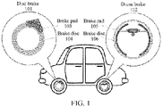
- FIG. 1 shows a schematic diagram of two typical friction brakes in an automobile. Specifically, FIG. 1 shows a schematic diagram of a disc brake 101 and a drum brake 102.
- the disc brake 101 may include a brake pad 103 and a brake disc 104 arranged to face each other, and the drum brake 102 may include a brake pad 105 and a brake disc 106 arranged to face each other. Both the disc brake 101 and the drum brake 102 can utilize contact friction of their respective brake pads and brake discs to implement braking and deceleration.
- the brake disc 104 in a shape of a disc ring may rotate with a wheel.
- the brake pads 103 in a shape of an incomplete ring sheet on two sides of the brake disc 104 may come into contact with the brake disc 104 under control of a system, to generate friction in a radial direction of the wheel.
- the disc brake 101 has advantages such as good heat dissipation, rapid response, and good constancy.
- the drum brake 102 may rotate with a wheel as a whole.
- the brake disc 106 in an annular cylinder shape is coaxial with the wheel, and the brake pad 105 in a shape of an incomplete cylinder shape on an inner side may come into contact with the brake disc 106 under control of a system, to generate friction in an axial direction of the wheel.
- the drum brake 102 has advantages such as low costs, a large contact area, and a high absolute braking force.
- the TENG is integrated and combined with the brake to a high extent, and further, an energy recovery circuit based on a mechanical switch on the brake is utilized, to convert mechanical energy into electric energy while braking and decelerating, to recover energy for use of a brake warning light or another in-vehicle device.
- an energy recovery circuit based on a mechanical switch on the brake is utilized, to convert mechanical energy into electric energy while braking and decelerating, to recover energy for use of a brake warning light or another in-vehicle device.
- a running status of the brake (for example, whether the brake is braking) may also be detected according to an output signal of the TENG. Implementation of this application is illustrated below in detail by using the disc brake 101 in the automobile as an example.
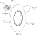
- FIG. 2 shows an exemplary external structure of a triboelectric generation apparatus based on a disc brake according to an embodiment of this application
- FIG. 3a and FIG. 3b respectively show an exemplary three-dimensional view and an exemplary side view of a triboelectric generation apparatus based on a disc brake according to an embodiment of this application in a braking state.
- a triboelectric generation apparatus 200 based on a disc brake may use the structure of the disc brake 101 shown in FIG. 1 .
- an exemplary external structure of the triboelectric generation apparatus 200 may be substantially the same as the external structure of the disc brake 101 shown in FIG. 1 .
- the disc brake may include a first friction component (for example, a brake disc 201) and a second friction component (for example, a brake pad 202 and/or a brake pad 203) arranged relative each other.
- the first friction component for example, the brake disc 201, may be in a shape of a disc ring.
- the second friction component for example, the brake pad 202 and the brake pad 203 may be in a shape of an incomplete ring sheet.
- the brake pad 202 and the brake pad 203 arranged on two sides of the brake disc 201 may not be in contact with the brake disc 201, and the brake disc 201 may rotate with a wheel.
- the brake pad 202 and the brake pad 203 arranged on the two sides of brake disc 201 may come into contact with the brake disc 201 under the control of the system, so that the brake disc 201 can generate contact friction relative to the brake pad 202 and the brake pad 203 and generate a friction braking force, to implement braking and deceleration.
- the brake disc 201 because of the triboelectric charging effect, when the brake disc 201 generates contact friction relative to the brake pad 202 and the brake pad 203, different electric charges may be generated on surfaces of the brake disc and the brake pads respectively.
- a friction plate 205 is arranged on an inner side of the second friction component (for example, the brake pad 202 and the brake pad 203), the inner side of the second friction component faces towards the first friction component (for example, the brake disc 201).
- a friction material of the first friction component has a first electric polarity
- a friction material of the friction plate 205 on the second friction component has a second electric polarity different from the first electric polarity.
- the second electric polarity may be opposite to the first electric polarity.
- different materials with opposite polarities in a triboelectric polarity sequence list or with a large position gap in the list may be respectively selected as a friction material of the first friction component and a material of the friction plate 205. In this way, a larger triboelectric charging quantity may be achieved.
- FIG. 2 , FIG. 3a, and FIG. 3b merely show an exemplary structure in which two brake pads are respectively arranged on opposite sides of the brake disc 201. It is to be understood that in another embodiment, the brake may include one or more brake pads arranged on one of or both sides of the brake disc 201, which is not limited herein.
- the triboelectric generation apparatus 200 based on a disc brake may include: a first sensing electrode and a second sensing electrode that are arranged in the first friction component.
- the first friction component for example, the brake disc 201
- the second friction component for example, the brake pad 202 and the brake pad 203
- the first friction component and the second friction component may generate friction electric charges with different polarities on friction surfaces thereof due to triboelectric charging, and a first induced electric charge may be further generated on the first sensing electrode and a second induced electric charge may be generated on the second sensing electrode due to electrostatic induction.
- the first induced electric charge is different from the second induced electric charge.
- the first induced electric charge may be a positive electric charge
- the second induced electric charge may be a negative electric charge, or vice versa.
- the first induced electric charge and the second induced electric charge may be different quantities of electric charges with the same polarity.
- the triboelectric generation apparatus 200 may further include an electric charge collection circuit (which, for example, is included in a circuit box 204 shown in FIG. 2 ), which may be connected to the first sensing electrode and the second sensing electrode, and store the electric charges collected from the first sensing electrode and the second sensing electrode, for use by a load.
- an electric charge collection circuit which, for example, is included in a circuit box 204 shown in FIG. 2 , which may be connected to the first sensing electrode and the second sensing electrode, and store the electric charges collected from the first sensing electrode and the second sensing electrode, for use by a load.
- the triboelectric generation apparatus 200 may further include: a reed switch arranged in the second friction component.
- the electric charge collection circuit may store the electric charges collected from the first sensing electrode and the second sensing electrode under the control of the reed switch.
- FIG. 4a and FIG. 4b respectively show a perspective view and a cross-sectional view of an exemplary structure of a brake disc of a triboelectric generation apparatus according to an embodiment of this application.
- the triboelectric generation apparatus 200 may include a sensing electrode 402 arranged in the first friction component (for example, the brake disc 201).
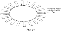
- FIG. 5a , FIG. 5b , and FIG. 5c show specific exemplary structures of a sensing electrode of a triboelectric generation apparatus according to an embodiment of this application.
- the sensing electrode 402 may include a first sensing electrode (for example, an outer comb-shaped sensing electrode 503) and a second sensing electrode (for example, an inner comb-shaped sensing electrode 504).
- a first sensing electrode for example, an outer comb-shaped sensing electrode 503
- a second sensing electrode for example, an inner comb-shaped sensing electrode 504
- the outer comb-shaped sensing electrode 503 and the inner comb-shaped sensing electrode 504 may be annular comb-shaped conductor. Comb teeth of the outer comb-shaped sensing electrode 503 and comb teeth of the inner comb-shaped sensing electrode 504 may be meshed with each other. In addition, there is no contact but a first gap between the outer comb-shaped sensing electrode 503 and the inner comb-shaped sensing electrode 504. In an embodiment, the comb teeth of the outer comb-shaped sensing electrode 503 and the comb teeth of the inner comb-shaped sensing electrode 504 may be distributed at equal distances.
- the outer comb-shaped sensing electrode 503 and the inner comb-shaped sensing electrode 504 may have the same quantity of comb teeth and may have the same comb tooth width and the same radial length.
- the quantities of the comb teeth and comb tooth shapes of the outer comb-shaped sensing electrode 503 and the inner comb-shaped sensing electrode 504 may be different according to a specific size and a specific shape of the brake disc 201.
- the outer comb-shaped sensing electrode 503 and the inner comb-shaped sensing electrode 504 may be made of a conductor with excellent electrical conductivity such as copper, nickel, gold, silver, aluminum, or iron.
- the triboelectric generation apparatus 200 may include a switch electrode 403 arranged in the first friction component (for example, the brake disc 201).
- the switch electrode 403 may be arranged on an inner ring of the brake disc 201.
- the switch electrode 403 may also be arranged on an outer ring (not shown) of the brake disc 201.
- FIG. 6a , FIG. 6b and FIG. 6c show specific exemplary structures of a switch electrode of a triboelectric generation apparatus according to an embodiment of this application. In an embodiment, as shown in FIG.
- the switch electrode 403 may include a first switch electrode and a second switch electrode.
- the first switch electrode may be an annular outer comb-shaped switch electrode 603, and the second switch electrode may be an annular inner comb-shaped switch electrode 604; or the first switch electrode may be an annular inner comb-shaped switch electrode 604, and the second switch electrode may be an annular outer comb-shaped switch electrode 603.
- the outer comb-shaped switch electrode 603 and the inner comb-shaped switch electrode 604 may be annular comb-shaped conductors.
- a quantity of comb teeth of the outer comb-shaped switch electrode 603 and a quantity of comb teeth of the inner comb-shaped switch electrode 604 may be both a first quantity, and the comb teeth of the outer comb-shaped switch electrode 603 and the comb teeth of the inner comb-shaped switch electrode 604 may be arranged opposite to each other to form a first quantity of comb tooth pairs, and there is no contact but a second gap between oppositely arranged comb teeth in each comb tooth pair.
- the outer comb-shaped switch electrode 603 and the inner comb-shaped switch electrode 604 that are arranged opposite to each other form a trapezoidal ring.
- the comb teeth of the outer comb-shaped switch electrode 603 and the comb teeth of the inner comb-shaped switch electrode 604 may be distributed at equal distances.
- the outer comb-shaped switch electrode 603 and the inner comb-shaped switch electrode 604 may be made of a conductor material that is wear-resistant, has excellent electrical conductivity, and is environmentally friendly.
- the above-described reed switch arranged in the second friction component may be utilized to control a mechanical connection between the outer comb-shaped switch electrode 603 and the inner comb-shaped switch electrode 604, to turn on or off of the circuit.
- a quantity of the comb teeth of outer comb-shaped sensing electrode 503 and a quantity of the comb teeth of the inner comb-shaped sensing electrode 504 may be both a second quantity.
- the first quantity of the comb teeth of the outer comb-shaped switch electrode 603 or the comb teeth of the inner comb-shaped switch electrode 604 may be two times the second quantity. For example, assuming that a quantity of the comb teeth of outer comb-shaped sensing electrode 503 and a quantity of the comb teeth of the inner comb-shaped sensing electrode 504 are both 25, a quantity of the comb teeth of the outer comb-shaped switch electrode 603 or the comb teeth of the inner comb-shaped switch electrode 604 may be 50.
- comb tooth pairs formed by opposite comb teeth of the outer comb-shaped switch electrode 603 and the inner comb-shaped switch electrode 604 have a one-to-one correspondence with the comb teeth of the outer comb-shaped sensing electrode 503 and the comb teeth of the inner comb-shaped sensing electrode 504.
- opposite comb teeth of the outer comb-shaped switch electrode 603 and the inner comb-shaped switch electrode 604 form a first quantity of comb tooth pairs.
- the first quantity of comb tooth pairs may have a one-to-one correspondence with the comb teeth of the outer comb-shaped sensing electrode 503 and the comb teeth of the inner comb-shaped sensing electrode 504.
- the comb tooth pairs of the outer comb-shaped switch electrode 603 and the inner comb-shaped switch electrode 604 may be arranged on edges of the respective comb teeth of the outer comb-shaped sensing electrode 503 and the inner comb-shaped sensing electrode 504 in a radial direction.
- a shape and a position of each comb tooth of the outer comb-shaped switch electrode 603 and the inner comb-shaped switch electrode 604, a shape and a position of an annular grid plates on the friction plate 205 described below, and a position of a reed switch on the brake pad 203 described below may be adaptively set according to shapes and positions of the comb teeth of the outer comb-shaped sensing electrode 503 and the inner comb-shaped sensing electrode 504, so that the comb tooth pairs formed by opposite comb teeth of the outer comb-shaped switch electrode 603 and the inner comb-shaped switch electrode 604 come into contact and conduct with the reed switch on the brake pad 203 for switch-on when the comb teeth of the outer comb-shaped sensing electrode 503 (or the comb teeth of the inner comb-shaped sensing electrode 504) overlap the annular grid plates on the friction plate 205.
- an output voltage between the outer comb-shaped sensing electrode 503 and the inner comb-shaped sensing electrode 504 is maximum.
- FIG. 7 shows an exemplary structure of a brake pad of a triboelectric generation apparatus according to an embodiment of this application.
- the second friction component (for example, the brake pad 202 and/or the brake pad 203) may be an incomplete ring sheet.
- a friction plate 205 is arranged on an inner side of the second friction component (for example, the brake pad 202 and/or the brake pad 203), the inner side of the second friction component faces towards the first friction component (for example, the brake disc 201).
- a friction material of the first friction component has a first electric polarity
- a friction material of the friction plate 205 on the second friction component has a second electric polarity different from the first electric polarity.
- the second electric polarity may be opposite to the first electric polarity.
- the disc ring of the first friction component may be coaxial with the incomplete ring sheet of the second friction component, and the first friction component may rotate around a center of the disc ring, to generate contact friction with the friction plate 205 on the second friction component.
- the friction plate 205 may include one or more annular grid plates.
- FIG. 7 shows a case in which the friction plate 205 includes multiple annular grid plates (for example, 6 annular grid plates).
- the friction plate 205 may include different quantities of annular grid plates with different widths.
- each of the annular grid plates may be radially arranged in an annular region corresponding to a region in which the comb teeth of the outer comb-shaped sensing electrode 503 and the comb teeth of the inner comb-shaped sensing electrode 504 are meshed with each other.
- Each of the annular grid plates has the same comb tooth shape as the comb teeth of the outer comb-shaped sensing electrode 503 or the comb teeth of the inner comb-shaped sensing electrode 504.
- the third gap may have the same width as a gap between adjacent comb teeth of the outer comb-shaped sensing electrode 503 or a gap between adjacent comb teeth of the inner comb-shaped sensing electrode 504.
- the annular grid plates on the friction plate 205 can completely overlap a quantity of successive comb teeth of the outer comb-shaped sensing electrode 503 or completely overlap a quantity of successive comb teeth of the inner comb-shaped sensing electrode 504.
- the above-described reed switch 701 may be arranged on an edge of the second friction component (for example, the brake pad 203) in a radial direction.
- the reed switch 701 may be wedge-shaped, and may be arranged parallel to the second gap.
- the second gap is a gap between a comb tooth pair of corresponding outer comb-shaped switch electrode 603 and inner comb-shaped switch electrode 604.
- a position of the reed switch 701 may also be determined according to shapes and positions of the comb teeth of the outer comb-shaped sensing electrode 503 and the inner comb-shaped sensing electrode 504, shapes and positions of the annular grid plates on the friction plate 205, and positions of comb tooth pairs of the outer comb-shaped switch electrode 603 and the inner comb-shaped switch electrode 604, so that the comb tooth pairs of the outer comb-shaped switch electrode 603 and the inner comb-shaped switch electrode 604 come into contact and conduct with the reed switch on the brake pad 203 when the comb teeth of the outer comb-shaped sensing electrode 503 (or the comb teeth of the inner comb-shaped sensing electrode 504) overlap the annular grid plates on the friction plate 205.
- an output voltage between the outer comb-shaped sensing electrode 503 and the inner comb-shaped sensing electrode 504 is maximum.
- the reed switch 701 may be arranged on any one of the two or more brake pads.
- a radial width of the reed switch 701 may be greater than a width of the second gap and less than a sum of a radial width of the outer comb-shaped switch electrode 603, a radial width of the inner comb-shaped switch electrode 604, and the width of the second gap therebetween.
- the ladder-shaped switch electrode 403 integrated on the brake disc 201 and the reed switch 701 integrated on the brake pad 203 constitute a mechanical contact switch.
- the switch electrode 403 in a case that an output voltage between the first sensing electrode and the second sensing electrode is maximum, the switch electrode 403 is switched on to output an electric charge, and in other cases, the switch electrode 403 is switched off and does not output an electric charge to the electric charge collection circuit.
- Such a ladder-shaped mechanical contact switch integrated on the brake can improve the stability and accuracy of the switch.
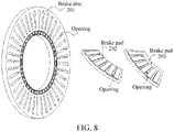
- FIG. 8 shows an opening structure of the triboelectric generation apparatus 200 according to an embodiment of this application.
- an opening may be provided at a position of the first friction component (for example, the brake disc 201) corresponding to the first gap, and an opening may be provided at a position of the second friction component (for example, the brake pad 202 and the brake pad 203) corresponding to the third gap.
- the first gap is a gap between the outer comb-shaped sensing electrode and the inner comb-shaped sensing electrode
- the third gap is a gap between the multiple annular grid plates.
- a triboelectric charging process and an electrostatic induction process of the triboelectric generation apparatus 200 based on some configurations in the foregoing embodiments are described below with reference to FIG. 9a and FIG. 9b .
- FIG. 9a and FIG. 9b show a triboelectric charging process and an electrostatic induction process of the triboelectric generation apparatus 200 according to an embodiment of this application.
- the figures merely show an annular grid plate 901 on the friction plate 205 and a pair of adjacent comb teeth of the outer comb-shaped sensing electrode sensing electrode 503 and the inner comb-shaped sensing electrode sensing 504 (that is, a comb tooth 902 of the outer comb-shaped sensing electrode sensing electrode and a comb tooth 903 of the inner comb-shaped sensing electrode).
- a left part of the comb tooth 902 of the outer comb-shaped sensing electrode that does not overlap the annular grid plate 901 is no longer affected by the negative electric charges on the annular grid plate 901, and only induces negative electric charges with a specific density under the impact of the positive electric charges generated by the friction of brake disc 201.
- a right part of the comb tooth 902 of the outer comb-shaped sensing electrode that overlaps the annular grid plate 901 is then affected by the negative electric charges on the annular grid plate 901, and induces positive electric charges.
- a left part of the comb tooth 903 of the inner comb-shaped sensing electrode that overlaps the annular grid plate 901 is affected by the negative electric charges on the annular grid plate 901, and induces positive electric charges with a specific density.
- an electric charge collection circuit electrically connected to the outer comb-shaped sensing electrode 503 and the inner comb-shaped sensing electrode 504 may be utilized to collect and store electric charges from the outer comb-shaped sensing electrode 503 and the inner comb-shaped sensing electrode 504.
- FIG. 10 shows a schematic circuit diagram of an electric charge collection circuit of a triboelectric generation apparatus according to an embodiment of this application.
- the electric charge collection circuit may include a rectifier circuit 1001 and an electric charge storage circuit 1002.
- the rectifier circuit 1001 may be a rectifier bridge circuit including multiple diodes.
- a first input terminal P1 of the rectifier circuit 1001 may be connected to the first sensing electrode (for example, the outer comb-shaped sensing electrode 503), and a second input terminal P2 of the rectifier circuit 1001 may be connected to the second sensing electrode (for example, the inner comb-shaped sensing electrode 504), and a first output terminal P3 of the rectifier circuit 1001 may be connected to the first switch electrode (for example, the outer comb-shaped switch electrode 603).
- the electric charge storage circuit 1002 may include devices such as a capacitor, an inductor, and a diode. As shown in FIG. 10 , a first input terminal P5 of the electric charge storage circuit 1002 may be connected to the second switch electrode (for example, the inner comb-shaped switch electrode 604), and a second input terminal P6 of the electric charge storage circuit 1002 may be connected to a second output terminal P4 of the rectifier circuit 1001.
- the second switch electrode for example, the inner comb-shaped switch electrode 604
- P6 of the electric charge storage circuit 1002 may be connected to a second output terminal P4 of the rectifier circuit 1001.
- the first switch electrode for example, the outer comb-shaped switch electrode 603 and the second switch electrode (for example, the inner comb-shaped switch electrode 604) may be turned on or off under the control of the reed switch, positions of the comb teeth of the switch electrodes and a position of the reed switch may be adjusted to switch on the circuit in a case that the output voltage between the first sensing electrode and the second sensing electrode is maximum.
- the electric charge storage circuit 1002 stores the electric charges collected from the first sensing electrode and the second sensing electrode into the inductor and/or the capacitor for subsequent use of a load.
- the circuit is switched on and collects and stores electric charges only when the output voltage between the first sensing electrode and the second sensing electrode is maximum, so that the high-impedance triboelectric generation apparatus can be impedance-decoupled from a load circuit, which improves the efficiency of the circuit under different loads.
- FIG. 11 shows a schematic diagram of a process for using an output of a sensing electrode according to an embodiment of this application for monitoring and analysis.
- an output of the sensing electrode 402 (for example, the outer comb-shaped sensing electrode 503 and the inner comb-shaped sensing electrode 504) may be directly connected to a signal analysis unit 1101 for analyzing the status of the brake. For example, whether the brake is currently braking or the like may be determined depending on whether an induced voltage is detected on the output of the sensing electrode 402.
- FIG. 12a and FIG. 12b show exemplary external structures of a triboelectric generation apparatus based on a drum brake according to an embodiment of this application.
- FIG. 12a and FIG. 12b show schematic structural diagrams of components of a triboelectric generation apparatus 300 based on a drum brake according to an embodiment of this application respectively in a case that the components are dispersed and in a case that the components are combined.
- the triboelectric generation apparatus 300 based on a drum brake according to an embodiment of this application may use the structure of the drum brake 102 shown in FIG. 1 .
- an exemplary external structure of the triboelectric generation apparatus 300 may be substantially the same as the external structure of the drum brake 102 shown in FIG. 1 .
- the drum brake may include a first friction component (for example, a brake disc 1201) and a second friction component (for example, a brake pad 1202 and/or a brake pad 1203) arranged to face each other.
- the brake disc 1201 may be in a shape of an annular cylinder, and the brake pad 1202 and the brake pad 1203 may be in a shape of an incomplete annular cylinder.
- the brake disc 1201 may be coaxial with the brake pad 1202 and the brake pad 1203, and the brake pad 1202 and the brake pad 1203 may be arranged on an inner side of the annular cylinder of the brake disc 1201.
- a sensing electrode 1205 (for example, including the first sensing electrode and the second sensing electrode that are comb-shaped and that are arranged crosswise) may be arranged on a surface of an outer ring of or inside the brake disc 1201.
- a switch electrode 1206 (for example, including the first switch electrode and the second switch electrode that are comb-shaped and that are arranged opposite to each other) may be arranged on a surface of an inner ring of the brake disc 1201.
- a grid-shaped friction plate 1207 may be arranged on outer surfaces of the brake pad 1202 and the brake pad 1203 that may come into contact with the brake disc 1201.
- a reed switch 1208 may further be arranged on one of the brake pad 1202 and the brake pad 1203 (for example, the brake pad 1203). Similar to the triboelectric generation apparatus 200 based on a disc brake, the electric charge collection circuit may also be integrated in a circuit box 1204.
- FIG. 13a and FIG. 13b respectively show side views of a triboelectric generation apparatus based on a drum brake according to an embodiment of this application in a non-braking state and a braking state.
- the brake pad 1202 and the brake pad 1203 arranged on an inner side of the brake disc 1201 may not be in contact with the brake disc 1201, and the brake disc 1201 may rotate with a wheel.
- the brake pad 1202 and the brake pad 1203 arranged on the inner side of brake disc 1201 may come into contact with the brake disc 1201 under the control of the system, so that the brake disc 1201 can generate contact friction relative to the brake pad 1202 and the brake pad 1203 and generate a friction braking force, to implement braking and deceleration.
- the first sensing electrode and the second sensing electrode of the sensing electrode 1205 can induce induced electric charges, and in a case that the reed switch 1208 on the brake pad 1203 switches on the switch electrode 1206 (that is, the first switch electrode and the second switch electrode are conducted with each other), the electric charges on the sensing electrode 1205 can be collected and stored to the circuit box 1204 for subsequent use of a load.
- a specific implementation of the triboelectric generation apparatus 300 based on a drum brake according to an embodiment of this application is similar to the triboelectric generation apparatus 200 based on a disc brake according to the foregoing embodiment of this application, and details are not described herein again.
- a friction brake is further provided according to an embodiment of this application, which includes: a brake disc and a brake pad that are arranged to face each other.
- the brake disc is configured to generate a friction braking force and an electric charge when contact friction occurs between the brake disc and the brake pad.
- the brake further includes a triboelectric generation apparatus.
- the triboelectric generation apparatus may include: a first sensing electrode and a second sensing electrode and an electric charge collection circuit. The first sensing electrode and the second sensing electrode are arranged in the brake disc.
- the electric charge collection circuit is connected to the first sensing electrode and the second sensing electrode, and is configured to store the electric charges collected from the first sensing electrode and the second sensing electrode.
- brake pads There may be one or more brake pads arranged to face the brake disc, and a quantity of the brake pads is not limited in this embodiment.
- a friction plate may be arranged on an inner side of the brake pad.
- the inner side of the brake pad may face towards the brake disc.
- a friction material of the brake disc may have a first electric polarity
- a friction material of the friction plate on the brake pad may have a second electric polarity different from the first electric polarity.
- the first electric polarity is opposite to the second electric polarity.
- the friction brake may be a disc brake.
- the brake disc may be in a shape of a disc ring, the brake pad may be an incomplete annular sheet, the brake disc and the brake pad may be coaxial, and the brake pad may be located on one or both sides of the brake disc.
- the friction brake may be a drum brake.
- the brake disc may be an annular cylinder
- the brake pad may be an incomplete annular cylinder
- the brake disc and the brake pad may be coaxial
- the brake pad may be located on an inner side of the brake disc.
- Specific structures of the friction brake and the triboelectric generation apparatus may be similar to the exemplary structures of the triboelectric generation apparatus 200 and the triboelectric generation apparatus 300 according to the foregoing embodiments of this application, and details are not described herein again.
- the triboelectric generation apparatus combines a triboelectric nanogenerator with a specific structure of the friction brake to a high extent by taking the structure of the friction brake into full consideration, which simplifies the structure and improves the reliability.
- a synchronous electric charge extraction circuit is used to decouple the impedance of the triboelectric nanogenerator and a load circuit, thereby improving the performance of the circuit under different loads; and a ladder-shaped mechanical contact switch is integrated onto the brake, thereby improving the stability and precision of a circuit switch.
Landscapes
- Engineering & Computer Science (AREA)
- General Engineering & Computer Science (AREA)
- Mechanical Engineering (AREA)
- Braking Arrangements (AREA)
Abstract
Description
- This application claims priority to
Chinese Patent Application No. 202010553081.3, entitled "FRICTION POWER GENERATION DEVICE BASED ON FRICTION BRAKE, AND FRICTION BRAKE" filed with the China National Intellectual Property Administration on June 17, 2020 - This application relates to the field of triboelectric generation technologies, and more specifically, to a triboelectric generation technology based on a friction brake.
- A braking process is a process to decelerate or stop a moving object, and widely exists in the fields of vehicle transportation, hoisting machinery, and construction machinery. The braking process may usually be implemented by using a brake. A friction brake may brake a moving object through frictional resistance, and has advantages of a simple structure and low cost. However, taking the friction brake as an example, a large amount of energy is often consumed in the braking process, which is mainly dissipated in the form of frictional heat, resulting in waste of a large amount of energy.
- At present, energy recovery solutions based on a braking process mainly include: (1) driving, through relative motion between brake components, an electromagnetic generator to rotate, thereby generating electric energy; (2) converting motion of an object into hydraulic potential energy in an hydraulic apparatus, to store energy; (3) using heat generated by friction between brake components to generate electricity with the help of thermoelectric reaction; (4) in new energy vehicles, directly reversing a motor to serve as a generator, and using a battery as a load to charge the battery, thereby decelerating while recovering energy; and (5) using a triboelectric nanogenerator to recover energy.
- However, some existing energy recovery solutions have low efficiency, complex structures, high maintenance costs, and low reliability, and do not fully consider the structural characteristics of the brake and circuit characteristics, such as the high impedance, of the energy recovery apparatus. The structural design of the energy recovery apparatus, the electrode accuracy and controllability of the energy recovery circuit, and the like need to be optimized and improved.
- A triboelectric generation apparatus based on a friction brake is provided according to an embodiment of this application. The friction brake includes a first friction component and a second friction component arranged to face each other, the first friction component is configured to generate a friction braking force and an electric charge when contact friction occurs between the first friction component and the second friction component. The triboelectric generation apparatus includes: a first sensing electrode and a second sensing electrode, and an electric charge collection circuit. The first sensing electrode and the second sensing electrode are arranged in the first friction component, when contact friction occurs between the first friction component and the second friction component, a first induced electric charge is generated on the first sensing electrode, and a second induced electric charge is generated on the second sensing electrode, the first induced electric charge is different from the second induced electric charge. The electric charge collection circuit is connected to the first sensing electrode and the second sensing electrode, and is configured to store the electric charges collected from the first sensing electrode and the second sensing electrode.
- According to an embodiment of this application, a friction plate is arranged on an inner side of the second friction component, the inner side of the second friction component faces towards the first friction component, a friction material of the first friction component has a first electric polarity, and a friction material of the friction plate on the second friction component has a second electric polarity, the first electric polarity is opposite to the second electric polarity.
- According to an embodiment of this application, the triboelectric generation apparatus further includes: a reed switch arranged in the second friction component, the electric charge collection circuit is further configured to store, under control of the reed switch, the electric charges collected from the first sensing electrode and the second sensing electrode.
- According to an embodiment of this application, the triboelectric generation apparatus further includes: a first switch electrode and a second switch electrode that are arranged in the first friction component. The electric charge collection circuit includes: a rectifier circuit and an electric charge storage circuit. A first input terminal of the rectifier circuit is connected to the first sensing electrode, a second input terminal of the rectifier circuit is connected to the second sensing electrode, and a first output terminal of the rectifier circuit is connected to the first switch electrode. A first input terminal of electric charge storage circuit is connected to the second switch electrode, and a second input terminal of electric charge storage circuit is connected to a second output terminal of the rectifier circuit. The reed switch is configured to control a connection between the first switch electrode and the second switch electrode. In a case that the first switch electrode is connected to the second switch electrode by the reed switch, the electric charge storage circuit is configured to store the electric charges collected from the first sensing electrode and the second sensing electrode.
- According to an embodiment of this application, the first friction component is in a shape of a disc ring, the first sensing electrode is an annular outer comb-shaped sensing electrode, and the second sensing electrode is an annular inner comb-shaped sensing electrode, comb teeth of the outer comb-shaped sensing electrode and comb teeth of the inner comb-shaped sensing electrode are meshed to each other, and a first gap is defined between the outer comb-shaped sensing electrode and the inner comb-shaped sensing electrode.
- According to an embodiment of this application, the first switch electrode and the second switch electrode are arranged on an inner ring or an outer ring of the first friction component. The first switch electrode is an annular outer comb-shaped switch electrode, and the second switch electrode is an annular inner comb-shaped switch electrode; or the first switch electrode is the annular inner comb-shaped switch electrode, the second switch electrode is the annular outer comb-shaped switch electrode. A quantity of comb teeth of the outer comb-shaped switch electrode and a quantity of comb teeth of the inner comb-shaped switch electrode are both a first quantity, and the comb teeth of the outer comb-shaped switch electrode and the comb teeth of the inner comb-shaped switch electrode are arranged opposite to each other to form a first quantity of comb tooth pairs, and a second gap is defined between oppositely arranged comb teeth in each of the comb tooth pairs, The reed switch is configured to control a mechanical connection between the outer comb-shaped switch electrode and the inner comb-shaped switch electrode.
- According to an embodiment of this application, a quantity of the comb teeth of the outer comb-shaped sensing electrode and a quantity of the comb teeth of the inner comb-shaped sensing electrode are both a second quantity, and the first quantity is two times the second quantity. The outer comb-shaped sensing electrode and the inner comb-shaped sensing electrode have a same comb tooth width and a same radial length, and the first quantity of comb tooth pairs have a one-to-one correspondence with the comb teeth of the outer comb-shaped sensing electrode and the comb teeth of the inner comb-shaped sensing electrode.
- According to an embodiment of this application, the comb tooth pairs of the outer comb-shaped switch electrode and the inner comb-shaped switch electrode are respectively arranged on edges of the comb teeth of the outer comb-shaped sensing electrode and the comb teeth of the inner comb-shaped sensing electrode in a radial direction. The reed switch is arranged on an edge of the second friction component in a radial direction, and is arranged parallel to the second gap, a radial width of the reed switch is greater than a width of the second gap, to conduct the outer comb-shaped switch electrode with the inner comb-shaped switch electrode when the reed switch is in contact with the outer comb-shaped switch electrode and the inner comb-shaped switch electrode.
- According to an embodiment of this application, the second friction component is an incomplete ring sheet, a friction plate is arranged on an inner side of the second friction component, the inner side of the second friction component faces towards the first friction component, and the first friction component is configured to rotate around a center of the disc ring, to generate contact friction with the friction plate on the second friction component. A friction material of the first friction component has a first electric polarity, and a friction material of the friction plate on the second friction component has a second electric polarity, the first electric polarity is opposite to the second electric polarity. The friction plate includes multiple annular grid plates, each of the annular grid plates is radially arranged in an annular region corresponding to a region in which the comb teeth of the outer comb-shaped sensing electrode and the comb teeth of the inner comb-shaped sensing electrode are meshed to each other. Each of the annular grid plates has a same comb tooth shape as the comb teeth of the outer comb-shaped sensing electrode or the comb teeth of the inner comb-shaped sensing electrode. A third gap is defined between adjacent annular grid plates of the annular grid plates, the third gap has the same width as a gap between adjacent comb teeth of the outer comb-shaped sensing electrode or a gap between adjacent comb teeth of the inner comb-shaped sensing electrode.
- According to an embodiment of this application, the first friction component is provided with an opening at a position corresponding to the first gap, and the second friction component is provided with an opening at a position corresponding to the third gap.
- According to an embodiment of this application, the outer comb-shaped sensing electrode and the inner comb-shaped sensing electrode are made of copper, nickel, gold, silver, aluminum, or iron.
- A friction brake is provided according to an embodiment of this application, which includes: a brake disc and a brake pad that are arranged to face each other. The brake disc is configured to generate a friction braking force and an electric charge when contact friction occurs between the brake disc and the brake pad. The brake further includes a triboelectric generation apparatus, the triboelectric generation apparatus includes: a first sensing electrode and a second sensing electrode, and an electric charge collection circuit. The first sensing electrode and the second sensing electrode are arranged in the brake disc, when contact friction occurs between the brake disc and the brake pad, a first induced electric charge is generated on the first sensing electrode, and a second induced electric charge is generated on the second sensing electrode, the first induced electric charge is different from the second induced electric charge. The electric charge collection circuit is connected to the first sensing electrode and the second sensing electrode, and is configured to store the electric charges collected from the first sensing electrode and the second sensing electrode.
- According to an embodiment of this application, a friction plate is arranged on an inner side of the brake pad, the inner side of the brake pad faces towards the brake disc. A friction material of the brake disc has a first electric polarity, and a friction material of the friction plate on the brake pad has a second electric polarity, the first electric polarity is opposite to the second electric polarity.
- According to an embodiment of this application, the friction brake is a disc brake, the brake disc is in a shape of a disc ring, the brake pad is an incomplete annular sheet, the brake disc and the brake pad are coaxial, and the brake pad is arranged on one of or both sides of the brake disc.
- According to an embodiment of this application, the friction brake is a drum brake, the brake disc is an annular cylinder, the brake pad is an incomplete annular cylinder, the brake disc and the brake pad are coaxial, and the brake pad bis arranged on an inner side of the brake disc.
- A triboelectric generation apparatus based on a friction brake and a friction brake are provided according to the embodiments of this application. The triboelectric generation apparatus takes the structure of the friction brake into full consideration. In a case that contact friction occurs between a first friction component and a second friction component in the friction brake, a first induced electric charge is generated on a first sensing electrode, a second induced electric charge is generated on a second sensing electrode, and an electric charge collection circuit is connected to the first sensing electrode and the second sensing electrode, to store the electric charges collected from the first sensing electrode and the second sensing electrode, thereby implementing collection for triboelectric generation. The apparatus combines a triboelectric nanogenerator with a specific structure of the friction brake to a high extent, which simplifies the structure and improves the reliability. A synchronous electric charge extraction circuit is used to decouple the impedance of the triboelectric nanogenerator and a load circuit, thereby improving the performance of the circuit under different loads; and a ladder-shaped mechanical contact switch is integrated onto the brake, thereby improving the stability and precision of a circuit switch.
- To describe the technical solutions in the embodiments more clearly, the drawings required for describing the embodiments of this application are briefly described in the following. Apparently, the drawings in the following description show only some embodiments of this application, and a person of ordinary skill in the art may still derive other drawings from these drawings without creative efforts.
-
FIG. 1 shows a schematic diagram of two typical friction brakes in an automobile. -
FIG. 2 shows an exemplary external structure of a triboelectric generation apparatus based on a disc brake according to an embodiment of this application. -
FIG. 3a and FIG. 3b respectively show an exemplary three-dimensional view and an exemplary side view of a triboelectric generation apparatus based on a disc brake according to an embodiment of this application in a braking state. -
FIG. 4a andFIG. 4b respectively show a perspective view and a cross-sectional view of an exemplary structure of a brake disc of a triboelectric generation apparatus according to an embodiment of this application. -
FIG. 5a ,FIG. 5b , andFIG. 5c show specific exemplary structures of a sensing electrode of a triboelectric generation apparatus according to an embodiment of this application. -
FIG. 6a ,FIG. 6b andFIG. 6c show specific exemplary structures of a switch electrode of a triboelectric generation apparatus according to an embodiment of this application. -
FIG. 7 shows an exemplary structure of a brake pad of a triboelectric generation apparatus according to an embodiment of this application. -
FIG. 8 shows an opening structure of a triboelectric generation apparatus according to an embodiment of this application. -
FIG. 9a andFIG. 9b show a triboelectric charging process and an electrostatic induction process of a triboelectric generation apparatus according to an embodiment of this application. -
FIG. 10 shows a schematic circuit diagram of an electric charge collection circuit of a triboelectric generation apparatus according to an embodiment of this application. -
FIG. 11 shows a schematic diagram of a process for using an output of a sensing electrode according to an embodiment of this application for monitoring and analysis. -
FIG. 12a andFIG. 12b show exemplary external structures of a triboelectric generation apparatus based on a drum brake according to an embodiment of this application. -
FIG. 13a and FIG. 13b show side views of a triboelectric generation apparatus based on a drum brake according to an embodiment of this application respectively in a non-braking state and a braking state. - To make objectives, technical solutions, and advantages of this application more clearly, exemplary embodiments according to this application are described below in detail with reference to the drawings. Apparently, the described embodiments are merely some but not all of the embodiments of this application. It is to be understood that, this application is not limited by the exemplary embodiments described herein.
- In this specification and the drawings, steps and elements that are substantially the same or similar are indicated by the same or similar reference signs, and repeated descriptions of such steps and elements will be omitted. In addition, in the descriptions of this application, the terms such as "first" and "second" are intended to distinguish the descriptions only, and are not to be understood as indicating or implying relative importance or a sequence.
- In this specification and the drawings of this application, elements are described in the singular or plural form according to the embodiments. However, the singular and plural forms are appropriately selected to be used in the described circumstances merely for ease of interpretation and are not intended to limit this application thereto. Therefore, the singular form includes the plural form, and the plural form also includes the singular form, unless the context clearly indicates otherwise.
- For ease of understanding, some concepts related to this application are first introduced below.
- A triboelectric nanogenerator (TENG) generates a movement of an electric charge through frictional motion between different materials based on the principles of triboelectric charging and electrostatic induction, to collect and utilize the electric charge, which is a process of converting mechanical energy into electric energy.
- A synchronized electric charge extraction (SECE) circuit includes devices such as bridges, switches, and inductors, and when an output voltage of the generator is maximum, the switches are turned on synchronously to extract all electric charges.
- A brake is an apparatus with functions such as decelerating or stopping a moving object or maintaining a moving object in a stopped state. The brake usually achieves braking and deceleration through contact friction between a brake disc and a brake pad.
- A brake pad is one of the components in the brake. A component in the brake that has a relatively small contact surface and that comes into contact with the brake disc under the driving and control of the system to generate contact friction is referred to as a brake pad, for example, a brake pad in a drum brake of an automobile.
- A brake disc is another important component in the brake that has a relatively large contact surface and that usually moves with the moving object, for example, a brake drum in a drum brake of an automobile.
- A braking process is a process to decelerate or stop a moving object, and widely exists in the fields of vehicle transportation, hoisting machinery, and construction machinery. The braking process may usually be implemented by using a brake. A friction brake may brake a moving object through frictional resistance, and has advantages of a simple structure and low cost. Taking braking in an automobile as an example, according to researches, energy consumed in a braking process accounts for about 27.5% of the total traction energy of the automobile under ECE-15 condition, while under the US EPA 75 Urban condition and the Japan 1015 condition that are closer to the urban traveling condition, proportions of energy consumed in a braking process reaches about 48.3% and 53% respectively. Taking a friction drum or disc brake (shown in
FIG. 1 ) commonly used in automobiles as an example, energy consumed by braking is mainly dissipated in the form of frictional heat. If this kind of energy can be recovered and utilized, it will be beneficial to improve the battery life and energy efficiency of the automobile. - The TENG may cause different materials to generate electric charges in a contact friction manner due to triboelectric charging, cause a directional movement of the electric charges through electrostatic induction, thereby converting mechanical energy into electric energy. The TENG in an independent layer mode has a higher mechanical energy-electric energy conversion efficiency, and may even reach 100% under ideal conditions. Therefore, the TENG may be combined with the brake, so that the simple one-way rotational motion of brake can achieve a high energy conversion efficiency, and mechanical energy in a braking process can be fully converted into electric energy.
- The embodiments of this application are further described below with reference to the drawings.
-
FIG. 1 shows a schematic diagram of two typical friction brakes in an automobile. Specifically,FIG. 1 shows a schematic diagram of adisc brake 101 and adrum brake 102. - As shown in
FIG. 1 , thedisc brake 101 may include abrake pad 103 and abrake disc 104 arranged to face each other, and thedrum brake 102 may include abrake pad 105 and abrake disc 106 arranged to face each other. Both thedisc brake 101 and thedrum brake 102 can utilize contact friction of their respective brake pads and brake discs to implement braking and deceleration. In a scenario of thedisc brake 101, thebrake disc 104 in a shape of a disc ring may rotate with a wheel. Thebrake pads 103 in a shape of an incomplete ring sheet on two sides of thebrake disc 104 may come into contact with thebrake disc 104 under control of a system, to generate friction in a radial direction of the wheel. Thedisc brake 101 has advantages such as good heat dissipation, rapid response, and good constancy. In a scenario of thedrum brake 102, thedrum brake 102 may rotate with a wheel as a whole. Thebrake disc 106 in an annular cylinder shape is coaxial with the wheel, and thebrake pad 105 in a shape of an incomplete cylinder shape on an inner side may come into contact with thebrake disc 106 under control of a system, to generate friction in an axial direction of the wheel. Thedrum brake 102 has advantages such as low costs, a large contact area, and a high absolute braking force. By taking a specific structure of the brake into full consideration, the TENG is integrated and combined with the brake to a high extent, and further, an energy recovery circuit based on a mechanical switch on the brake is utilized, to convert mechanical energy into electric energy while braking and decelerating, to recover energy for use of a brake warning light or another in-vehicle device. In addition, a running status of the brake (for example, whether the brake is braking) may also be detected according to an output signal of the TENG. Implementation of this application is illustrated below in detail by using thedisc brake 101 in the automobile as an example. -
FIG. 2 shows an exemplary external structure of a triboelectric generation apparatus based on a disc brake according to an embodiment of this application, andFIG. 3a and FIG. 3b respectively show an exemplary three-dimensional view and an exemplary side view of a triboelectric generation apparatus based on a disc brake according to an embodiment of this application in a braking state. - As shown in
FIG. 2 , atriboelectric generation apparatus 200 based on a disc brake according to an embodiment of this application may use the structure of thedisc brake 101 shown inFIG. 1 . For example, an exemplary external structure of thetriboelectric generation apparatus 200 may be substantially the same as the external structure of thedisc brake 101 shown inFIG. 1 . In the embodiment shown inFIG. 2 , the disc brake may include a first friction component (for example, a brake disc 201) and a second friction component (for example, abrake pad 202 and/or a brake pad 203) arranged relative each other. As shown inFIG. 2 , the first friction component, for example, thebrake disc 201, may be in a shape of a disc ring. The second friction component, for example, thebrake pad 202 and thebrake pad 203 may be in a shape of an incomplete ring sheet. In a non-braking state, thebrake pad 202 and thebrake pad 203 arranged on two sides of thebrake disc 201 may not be in contact with thebrake disc 201, and thebrake disc 201 may rotate with a wheel. In a braking state, as shown inFIG. 3a and FIG. 3b , thebrake pad 202 and thebrake pad 203 arranged on the two sides ofbrake disc 201 may come into contact with thebrake disc 201 under the control of the system, so that thebrake disc 201 can generate contact friction relative to thebrake pad 202 and thebrake pad 203 and generate a friction braking force, to implement braking and deceleration. In addition, because of the triboelectric charging effect, when thebrake disc 201 generates contact friction relative to thebrake pad 202 and thebrake pad 203, different electric charges may be generated on surfaces of the brake disc and the brake pads respectively. - In an embodiment, a
friction plate 205 is arranged on an inner side of the second friction component (for example, thebrake pad 202 and the brake pad 203), the inner side of the second friction component faces towards the first friction component (for example, the brake disc 201). A friction material of the first friction component has a first electric polarity, and a friction material of thefriction plate 205 on the second friction component has a second electric polarity different from the first electric polarity. For example, the second electric polarity may be opposite to the first electric polarity. For example, different materials with opposite polarities in a triboelectric polarity sequence list or with a large position gap in the list may be respectively selected as a friction material of the first friction component and a material of thefriction plate 205. In this way, a larger triboelectric charging quantity may be achieved. -
FIG. 2 ,FIG. 3a, and FIG. 3b merely show an exemplary structure in which two brake pads are respectively arranged on opposite sides of thebrake disc 201. It is to be understood that in another embodiment, the brake may include one or more brake pads arranged on one of or both sides of thebrake disc 201, which is not limited herein. - In an embodiment, the
triboelectric generation apparatus 200 based on a disc brake according to an embodiment of this application may include: a first sensing electrode and a second sensing electrode that are arranged in the first friction component. As described above, when the first friction component (for example, the brake disc 201) generates contact friction relative to the second friction component (for example, thebrake pad 202 and the brake pad 203), the first friction component and the second friction component may generate friction electric charges with different polarities on friction surfaces thereof due to triboelectric charging, and a first induced electric charge may be further generated on the first sensing electrode and a second induced electric charge may be generated on the second sensing electrode due to electrostatic induction. The first induced electric charge is different from the second induced electric charge. For example, the first induced electric charge may be a positive electric charge, and the second induced electric charge may be a negative electric charge, or vice versa. In another example, for example, the first induced electric charge and the second induced electric charge may be different quantities of electric charges with the same polarity. A specific triboelectric charging process and a specific electrostatic induction process are described below in detail with reference toFIG. 9a andFIG. 9b . - In an embodiment, the
triboelectric generation apparatus 200 may further include an electric charge collection circuit (which, for example, is included in acircuit box 204 shown inFIG. 2 ), which may be connected to the first sensing electrode and the second sensing electrode, and store the electric charges collected from the first sensing electrode and the second sensing electrode, for use by a load. - In an embodiment, the
triboelectric generation apparatus 200 may further include: a reed switch arranged in the second friction component. In addition, the electric charge collection circuit may store the electric charges collected from the first sensing electrode and the second sensing electrode under the control of the reed switch. A specific exemplary structure of thetriboelectric generation apparatus 200 according to an embodiment of this application is described below in detail with reference toFIG. 4a to FIG. 8 . -
FIG. 4a andFIG. 4b respectively show a perspective view and a cross-sectional view of an exemplary structure of a brake disc of a triboelectric generation apparatus according to an embodiment of this application. - As shown in
FIG. 4a , thetriboelectric generation apparatus 200 may include asensing electrode 402 arranged in the first friction component (for example, the brake disc 201).FIG. 5a ,FIG. 5b , andFIG. 5c show specific exemplary structures of a sensing electrode of a triboelectric generation apparatus according to an embodiment of this application. In an embodiment, as shown inFIG. 5a , thesensing electrode 402 may include a first sensing electrode (for example, an outer comb-shaped sensing electrode 503) and a second sensing electrode (for example, an inner comb-shaped sensing electrode 504). As shown inFIG. 5a to FIG. 5c , based on the disc ring structure of thebrake disc 201, the outer comb-shapedsensing electrode 503 and the inner comb-shapedsensing electrode 504 may be annular comb-shaped conductor. Comb teeth of the outer comb-shapedsensing electrode 503 and comb teeth of the inner comb-shapedsensing electrode 504 may be meshed with each other. In addition, there is no contact but a first gap between the outer comb-shapedsensing electrode 503 and the inner comb-shapedsensing electrode 504. In an embodiment, the comb teeth of the outer comb-shapedsensing electrode 503 and the comb teeth of the inner comb-shapedsensing electrode 504 may be distributed at equal distances. In an embodiment, the outer comb-shapedsensing electrode 503 and the inner comb-shapedsensing electrode 504 may have the same quantity of comb teeth and may have the same comb tooth width and the same radial length. The quantities of the comb teeth and comb tooth shapes of the outer comb-shapedsensing electrode 503 and the inner comb-shapedsensing electrode 504 may be different according to a specific size and a specific shape of thebrake disc 201. In an embodiment, the outer comb-shapedsensing electrode 503 and the inner comb-shapedsensing electrode 504 may be made of a conductor with excellent electrical conductivity such as copper, nickel, gold, silver, aluminum, or iron. - In an embodiment, as shown in
FIG. 4a , thetriboelectric generation apparatus 200 may include aswitch electrode 403 arranged in the first friction component (for example, the brake disc 201). For example, as shown inFIG. 4a , based on the disc ring structure of thebrake disc 201, theswitch electrode 403 may be arranged on an inner ring of thebrake disc 201. In another embodiment, theswitch electrode 403 may also be arranged on an outer ring (not shown) of thebrake disc 201.FIG. 6a ,FIG. 6b andFIG. 6c show specific exemplary structures of a switch electrode of a triboelectric generation apparatus according to an embodiment of this application. In an embodiment, as shown inFIG. 6a , theswitch electrode 403 may include a first switch electrode and a second switch electrode. For example, as shown inFIG. 6a , the first switch electrode may be an annular outer comb-shapedswitch electrode 603, and the second switch electrode may be an annular inner comb-shapedswitch electrode 604; or the first switch electrode may be an annular inner comb-shapedswitch electrode 604, and the second switch electrode may be an annular outer comb-shapedswitch electrode 603. As shown inFIG. 6a to FIG. 6c , the outer comb-shapedswitch electrode 603 and the inner comb-shapedswitch electrode 604 may be annular comb-shaped conductors. A quantity of comb teeth of the outer comb-shapedswitch electrode 603 and a quantity of comb teeth of the inner comb-shapedswitch electrode 604 may be both a first quantity, and the comb teeth of the outer comb-shapedswitch electrode 603 and the comb teeth of the inner comb-shapedswitch electrode 604 may be arranged opposite to each other to form a first quantity of comb tooth pairs, and there is no contact but a second gap between oppositely arranged comb teeth in each comb tooth pair. As shown inFIG. 6a , the outer comb-shapedswitch electrode 603 and the inner comb-shapedswitch electrode 604 that are arranged opposite to each other form a trapezoidal ring. In an embodiment, the comb teeth of the outer comb-shapedswitch electrode 603 and the comb teeth of the inner comb-shapedswitch electrode 604 may be distributed at equal distances. In an embodiment, the outer comb-shapedswitch electrode 603 and the inner comb-shapedswitch electrode 604 may be made of a conductor material that is wear-resistant, has excellent electrical conductivity, and is environmentally friendly. In an embodiment, the above-described reed switch arranged in the second friction component may be utilized to control a mechanical connection between the outer comb-shapedswitch electrode 603 and the inner comb-shapedswitch electrode 604, to turn on or off of the circuit. - In an embodiment, a quantity of the comb teeth of outer comb-shaped
sensing electrode 503 and a quantity of the comb teeth of the inner comb-shapedsensing electrode 504 may be both a second quantity. In addition, the first quantity of the comb teeth of the outer comb-shapedswitch electrode 603 or the comb teeth of the inner comb-shapedswitch electrode 604 may be two times the second quantity. For example, assuming that a quantity of the comb teeth of outer comb-shapedsensing electrode 503 and a quantity of the comb teeth of the inner comb-shapedsensing electrode 504 are both 25, a quantity of the comb teeth of the outer comb-shapedswitch electrode 603 or the comb teeth of the inner comb-shapedswitch electrode 604 may be 50. In this way, comb tooth pairs formed by opposite comb teeth of the outer comb-shapedswitch electrode 603 and the inner comb-shapedswitch electrode 604 have a one-to-one correspondence with the comb teeth of the outer comb-shapedsensing electrode 503 and the comb teeth of the inner comb-shapedsensing electrode 504. - In an embodiment, as shown in
FIG. 4a , opposite comb teeth of the outer comb-shapedswitch electrode 603 and the inner comb-shapedswitch electrode 604 form a first quantity of comb tooth pairs. The first quantity of comb tooth pairs may have a one-to-one correspondence with the comb teeth of the outer comb-shapedsensing electrode 503 and the comb teeth of the inner comb-shapedsensing electrode 504. In addition, the comb tooth pairs of the outer comb-shapedswitch electrode 603 and the inner comb-shapedswitch electrode 604 may be arranged on edges of the respective comb teeth of the outer comb-shapedsensing electrode 503 and the inner comb-shapedsensing electrode 504 in a radial direction. - In another embodiment, a shape and a position of each comb tooth of the outer comb-shaped
switch electrode 603 and the inner comb-shapedswitch electrode 604, a shape and a position of an annular grid plates on thefriction plate 205 described below, and a position of a reed switch on thebrake pad 203 described below may be adaptively set according to shapes and positions of the comb teeth of the outer comb-shapedsensing electrode 503 and the inner comb-shapedsensing electrode 504, so that the comb tooth pairs formed by opposite comb teeth of the outer comb-shapedswitch electrode 603 and the inner comb-shapedswitch electrode 604 come into contact and conduct with the reed switch on thebrake pad 203 for switch-on when the comb teeth of the outer comb-shaped sensing electrode 503 (or the comb teeth of the inner comb-shaped sensing electrode 504) overlap the annular grid plates on thefriction plate 205. In this case, (that is, in a case that the comb teeth of the outer comb-shapedsensing electrode 503 or the inner comb-shapedsensing electrode 504 overlap the annular grid plates on the friction plate 205), an output voltage between the outer comb-shapedsensing electrode 503 and the inner comb-shapedsensing electrode 504 is maximum. A specific principle is described below with reference toFIG. 9a andFIG. 9b . - Next,
FIG. 7 shows an exemplary structure of a brake pad of a triboelectric generation apparatus according to an embodiment of this application. - As shown in
FIG. 7 , in an embodiment, the second friction component (for example, thebrake pad 202 and/or the brake pad 203) may be an incomplete ring sheet. In an embodiment, as described above, afriction plate 205 is arranged on an inner side of the second friction component (for example, thebrake pad 202 and/or the brake pad 203), the inner side of the second friction component faces towards the first friction component (for example, the brake disc 201). A friction material of the first friction component has a first electric polarity, and a friction material of thefriction plate 205 on the second friction component has a second electric polarity different from the first electric polarity. For example, the second electric polarity may be opposite to the first electric polarity. In an embodiment, the disc ring of the first friction component may be coaxial with the incomplete ring sheet of the second friction component, and the first friction component may rotate around a center of the disc ring, to generate contact friction with thefriction plate 205 on the second friction component. - In an embodiment, as shown in
FIG. 7 , thefriction plate 205 may include one or more annular grid plates.FIG. 7 shows a case in which thefriction plate 205 includes multiple annular grid plates (for example, 6 annular grid plates). In another embodiment, according to different sizes of the brake pad and different comb tooth widths of comb-shaped sensing electrodes in the brake disc, thefriction plate 205 may include different quantities of annular grid plates with different widths. According to an embodiment of this application, each of the annular grid plates may be radially arranged in an annular region corresponding to a region in which the comb teeth of the outer comb-shapedsensing electrode 503 and the comb teeth of the inner comb-shapedsensing electrode 504 are meshed with each other. Each of the annular grid plates has the same comb tooth shape as the comb teeth of the outer comb-shapedsensing electrode 503 or the comb teeth of the inner comb-shapedsensing electrode 504. In an embodiment, there is a third gap between adjacent annular grid plates of the annular grid plates. In addition, the third gap may have the same width as a gap between adjacent comb teeth of the outer comb-shapedsensing electrode 503 or a gap between adjacent comb teeth of the inner comb-shapedsensing electrode 504. With such an arrangement, in a process in which the brake disc rotates relative to the brake pad, the annular grid plates on thefriction plate 205 can completely overlap a quantity of successive comb teeth of the outer comb-shapedsensing electrode 503 or completely overlap a quantity of successive comb teeth of the inner comb-shapedsensing electrode 504. - In an embodiment, as shown in
FIG. 7 , the above-describedreed switch 701 may be arranged on an edge of the second friction component (for example, the brake pad 203) in a radial direction. Thereed switch 701 may be wedge-shaped, and may be arranged parallel to the second gap. The second gap is a gap between a comb tooth pair of corresponding outer comb-shapedswitch electrode 603 and inner comb-shapedswitch electrode 604. In another embodiment, as described above, a position of thereed switch 701 may also be determined according to shapes and positions of the comb teeth of the outer comb-shapedsensing electrode 503 and the inner comb-shapedsensing electrode 504, shapes and positions of the annular grid plates on thefriction plate 205, and positions of comb tooth pairs of the outer comb-shapedswitch electrode 603 and the inner comb-shapedswitch electrode 604, so that the comb tooth pairs of the outer comb-shapedswitch electrode 603 and the inner comb-shapedswitch electrode 604 come into contact and conduct with the reed switch on thebrake pad 203 when the comb teeth of the outer comb-shaped sensing electrode 503 (or the comb teeth of the inner comb-shaped sensing electrode 504) overlap the annular grid plates on thefriction plate 205. In this case (that is, in a case that the comb teeth of the outer comb-shapedsensing electrode 503 or the inner comb-shapedsensing electrode 504 overlap the annular grid plates on the friction plate 205), an output voltage between the outer comb-shapedsensing electrode 503 and the inner comb-shapedsensing electrode 504 is maximum. A specific principle is described below with reference toFIG. 9a andFIG. 9b . - It is to be understood that, as shown in
FIG. 7 , in a case that there are two or more brake pads, thereed switch 701 may be arranged on any one of the two or more brake pads. - In an embodiment, a radial width of the
reed switch 701 may be greater than a width of the second gap and less than a sum of a radial width of the outer comb-shapedswitch electrode 603, a radial width of the inner comb-shapedswitch electrode 604, and the width of the second gap therebetween. With such an arrangement, when thereed switch 701 comes into contact with the outer comb-shapedswitch electrode 603 and the inner comb-shapedswitch electrode 604, the outer comb-shapedswitch electrode 603 and the inner comb-shapedswitch electrode 604 are conducted with each other, and thereed switch 701 does not generate contact friction at other undesired position on thetriboelectric generation apparatus 200. - According to an embodiment of this application, the ladder-shaped
switch electrode 403 integrated on thebrake disc 201 and thereed switch 701 integrated on thebrake pad 203 constitute a mechanical contact switch. As described above, with such an arrangement, in a case that an output voltage between the first sensing electrode and the second sensing electrode is maximum, theswitch electrode 403 is switched on to output an electric charge, and in other cases, theswitch electrode 403 is switched off and does not output an electric charge to the electric charge collection circuit. Such a ladder-shaped mechanical contact switch integrated on the brake can improve the stability and accuracy of the switch. - In addition,
FIG. 8 shows an opening structure of thetriboelectric generation apparatus 200 according to an embodiment of this application. As shown inFIG. 8 , an opening may be provided at a position of the first friction component (for example, the brake disc 201) corresponding to the first gap, and an opening may be provided at a position of the second friction component (for example, thebrake pad 202 and the brake pad 203) corresponding to the third gap. The first gap is a gap between the outer comb-shaped sensing electrode and the inner comb-shaped sensing electrode, and the third gap is a gap between the multiple annular grid plates. With such an arrangement, better drainage or a better heat dissipation effect can be achieved in the braking process, and the service life of thetriboelectric generation apparatus 200 can be prolonged. - A triboelectric charging process and an electrostatic induction process of the
triboelectric generation apparatus 200 based on some configurations in the foregoing embodiments are described below with reference toFIG. 9a andFIG. 9b . -
FIG. 9a andFIG. 9b show a triboelectric charging process and an electrostatic induction process of thetriboelectric generation apparatus 200 according to an embodiment of this application. To simplify the description, the figures merely show anannular grid plate 901 on thefriction plate 205 and a pair of adjacent comb teeth of the outer comb-shaped sensingelectrode sensing electrode 503 and the inner comb-shaped sensing electrode sensing 504 (that is, acomb tooth 902 of the outer comb-shaped sensing electrode sensing electrode and acomb tooth 903 of the inner comb-shaped sensing electrode). - As shown in
FIG. 9a , in a braking process, assuming that theannular grid plate 901 frictionally slides from left to right relative to thebrake disc 201 in a direction as indicated by an arrow, and assuming that a friction material of theannular grid plate 901 has a frictional negative polarity, and a friction material of thebrake disc 201 has a frictional positive polarity, in the braking process, due to the triboelectric charging effect, a frictional surface of theannular grid plate 901 may generate a negative electric charge, and a friction surface of thebrake disc 201 may generate a positive electric charge. Assuming that a density of positive electric charges generated by the friction material of thebrake disc 201 due to triboelectric charging is lower than a density of negative electric charges on theannual grid plate 901, at a relative position shown inFIG. 9a , positive electric charges with a specific density will be induced on thecomb tooth 902 of the outer comb-shaped sensing electrode due to electrostatic induction, and negative electric charges with a specific density are induced on thecomb tooth 903 of the inner comb-shaped sensing electrode due to the positive electric charges on thebrake disc 201. - In a case that the
annular grid plate 901 frictionally slides to the right relative to thebrake disc 201 by a specific distance, as shown inFIG. 9b , a left part of thecomb tooth 902 of the outer comb-shaped sensing electrode that does not overlap theannular grid plate 901 is no longer affected by the negative electric charges on theannular grid plate 901, and only induces negative electric charges with a specific density under the impact of the positive electric charges generated by the friction ofbrake disc 201. A right part of thecomb tooth 902 of the outer comb-shaped sensing electrode that overlaps theannular grid plate 901 is then affected by the negative electric charges on theannular grid plate 901, and induces positive electric charges. At the same time, a left part of thecomb tooth 903 of the inner comb-shaped sensing electrode that overlaps theannular grid plate 901 is affected by the negative electric charges on theannular grid plate 901, and induces positive electric charges with a specific density. - Therefore, in a case that the
annular grid plate 901 frictionally slides from a position at which theannular grid plate 901 completely overlap thecomb tooth 902 of the outer comb-shaped sensing electrode (as shown inFIG. 9a ) to a position at which theannular grid plate 901 completely overlap thecomb tooth 903 of the inner comb-shaped sensing electrode, positive electric charges are transferred from thecomb tooth 902 of the outer comb-shaped sensing electrode to thecomb tooth 903 of the inner comb-shaped sensing electrode due to electrostatic induction. Similarly, in a case that theannular grid plate 901 continues to frictionally slide from the position at which theannular grid plate 901 completely overlap thecomb tooth 903 of the inner comb-shaped sensing electrode to a position at which theannular grid plate 901 completely overlap a next comb tooth of the outer comb-shaped sensing electrode (not shown), positive electric charges are transferred from thecomb tooth 903 of the inner comb-shaped sensing electrode to the next comb tooth of the outer comb-shaped sensing electrode. In such alternation manner, the positive electric charges are mutually transferred between the outer comb-shapedsensing electrode 503 and the inner comb-shapedsensing electrode 504. In a case that thecomb tooth 902 of the outer comb-shaped sensing electrode and thecomb tooth 903 of the inner comb-shaped sensing electrode are used as two poles of a power supply, power can be supplied to an external load. - In an embodiment, as described above, an electric charge collection circuit electrically connected to the outer comb-shaped
sensing electrode 503 and the inner comb-shapedsensing electrode 504 may be utilized to collect and store electric charges from the outer comb-shapedsensing electrode 503 and the inner comb-shapedsensing electrode 504. -
FIG. 10 shows a schematic circuit diagram of an electric charge collection circuit of a triboelectric generation apparatus according to an embodiment of this application. - As shown in
FIG. 10 , in an embodiment, the electric charge collection circuit may include arectifier circuit 1001 and an electriccharge storage circuit 1002. - The
rectifier circuit 1001 may be a rectifier bridge circuit including multiple diodes. A first input terminal P1 of therectifier circuit 1001 may be connected to the first sensing electrode (for example, the outer comb-shaped sensing electrode 503), and a second input terminal P2 of therectifier circuit 1001 may be connected to the second sensing electrode (for example, the inner comb-shaped sensing electrode 504), and a first output terminal P3 of therectifier circuit 1001 may be connected to the first switch electrode (for example, the outer comb-shaped switch electrode 603). - The electric
charge storage circuit 1002 may include devices such as a capacitor, an inductor, and a diode. As shown inFIG. 10 , a first input terminal P5 of the electriccharge storage circuit 1002 may be connected to the second switch electrode (for example, the inner comb-shaped switch electrode 604), and a second input terminal P6 of the electriccharge storage circuit 1002 may be connected to a second output terminal P4 of therectifier circuit 1001. - As described above, the first switch electrode (for example, the outer comb-shaped switch electrode 603) and the second switch electrode (for example, the inner comb-shaped switch electrode 604) may be turned on or off under the control of the reed switch, positions of the comb teeth of the switch electrodes and a position of the reed switch may be adjusted to switch on the circuit in a case that the output voltage between the first sensing electrode and the second sensing electrode is maximum. In a case that the first switch electrode is connected to (switches on) the second switch electrode by the reed switch, the electric
charge storage circuit 1002 stores the electric charges collected from the first sensing electrode and the second sensing electrode into the inductor and/or the capacitor for subsequent use of a load. By using the mechanical contact switch that integrates the electric charge collection circuit and the brake to a high extent according to an embodiment of this application, the circuit is switched on and collects and stores electric charges only when the output voltage between the first sensing electrode and the second sensing electrode is maximum, so that the high-impedance triboelectric generation apparatus can be impedance-decoupled from a load circuit, which improves the efficiency of the circuit under different loads. - In addition, the output of the sensing electrode may also be used as a monitoring signal for monitoring a status of the brake.
FIG. 11 shows a schematic diagram of a process for using an output of a sensing electrode according to an embodiment of this application for monitoring and analysis. As shown inFIG. 11 , an output of the sensing electrode 402 (for example, the outer comb-shapedsensing electrode 503 and the inner comb-shaped sensing electrode 504) may be directly connected to asignal analysis unit 1101 for analyzing the status of the brake. For example, whether the brake is currently braking or the like may be determined depending on whether an induced voltage is detected on the output of thesensing electrode 402. - In addition,
FIG. 12a andFIG. 12b show exemplary external structures of a triboelectric generation apparatus based on a drum brake according to an embodiment of this application. -
FIG. 12a andFIG. 12b show schematic structural diagrams of components of atriboelectric generation apparatus 300 based on a drum brake according to an embodiment of this application respectively in a case that the components are dispersed and in a case that the components are combined. As shown inFIG. 12b , thetriboelectric generation apparatus 300 based on a drum brake according to an embodiment of this application may use the structure of thedrum brake 102 shown inFIG. 1 . For example, an exemplary external structure of thetriboelectric generation apparatus 300 may be substantially the same as the external structure of thedrum brake 102 shown inFIG. 1 . - In the embodiment shown in
FIG. 12b , the drum brake may include a first friction component (for example, a brake disc 1201) and a second friction component (for example, abrake pad 1202 and/or a brake pad 1203) arranged to face each other. As shown inFIG. 12a orFIG. 12b , thebrake disc 1201 may be in a shape of an annular cylinder, and thebrake pad 1202 and thebrake pad 1203 may be in a shape of an incomplete annular cylinder. Thebrake disc 1201 may be coaxial with thebrake pad 1202 and thebrake pad 1203, and thebrake pad 1202 and thebrake pad 1203 may be arranged on an inner side of the annular cylinder of thebrake disc 1201. A sensing electrode 1205 (for example, including the first sensing electrode and the second sensing electrode that are comb-shaped and that are arranged crosswise) may be arranged on a surface of an outer ring of or inside thebrake disc 1201. A switch electrode 1206 (for example, including the first switch electrode and the second switch electrode that are comb-shaped and that are arranged opposite to each other) may be arranged on a surface of an inner ring of thebrake disc 1201. A grid-shapedfriction plate 1207 may be arranged on outer surfaces of thebrake pad 1202 and thebrake pad 1203 that may come into contact with thebrake disc 1201. In addition, areed switch 1208 may further be arranged on one of thebrake pad 1202 and the brake pad 1203 (for example, the brake pad 1203). Similar to thetriboelectric generation apparatus 200 based on a disc brake, the electric charge collection circuit may also be integrated in acircuit box 1204. -
FIG. 13a and FIG. 13b respectively show side views of a triboelectric generation apparatus based on a drum brake according to an embodiment of this application in a non-braking state and a braking state. - As shown in
FIG. 13a , in a non-braking state, thebrake pad 1202 and thebrake pad 1203 arranged on an inner side of thebrake disc 1201 may not be in contact with thebrake disc 1201, and thebrake disc 1201 may rotate with a wheel. In a braking state, as shown inFIG. 13b , thebrake pad 1202 and thebrake pad 1203 arranged on the inner side ofbrake disc 1201 may come into contact with thebrake disc 1201 under the control of the system, so that thebrake disc 1201 can generate contact friction relative to thebrake pad 1202 and thebrake pad 1203 and generate a friction braking force, to implement braking and deceleration. In a braking state, the first sensing electrode and the second sensing electrode of thesensing electrode 1205 can induce induced electric charges, and in a case that thereed switch 1208 on thebrake pad 1203 switches on the switch electrode 1206 (that is, the first switch electrode and the second switch electrode are conducted with each other), the electric charges on thesensing electrode 1205 can be collected and stored to thecircuit box 1204 for subsequent use of a load. A specific implementation of thetriboelectric generation apparatus 300 based on a drum brake according to an embodiment of this application is similar to thetriboelectric generation apparatus 200 based on a disc brake according to the foregoing embodiment of this application, and details are not described herein again. - A friction brake is further provided according to an embodiment of this application, which includes: a brake disc and a brake pad that are arranged to face each other. The brake disc is configured to generate a friction braking force and an electric charge when contact friction occurs between the brake disc and the brake pad. The brake further includes a triboelectric generation apparatus. The triboelectric generation apparatus may include: a first sensing electrode and a second sensing electrode and an electric charge collection circuit. The first sensing electrode and the second sensing electrode are arranged in the brake disc. when contact friction occurs between the brake disc and the brake pad, a first induced electric charge may be generated on the first sensing electrode, and a second induced electric charge may be generated on the second sensing electrode, the first induced electric charge is different from the second induced electric charge. The electric charge collection circuit is connected to the first sensing electrode and the second sensing electrode, and is configured to store the electric charges collected from the first sensing electrode and the second sensing electrode.
- There may be one or more brake pads arranged to face the brake disc, and a quantity of the brake pads is not limited in this embodiment.
- In an embodiment, a friction plate may be arranged on an inner side of the brake pad. The inner side of the brake pad may face towards the brake disc. In an embodiment, a friction material of the brake disc may have a first electric polarity, and a friction material of the friction plate on the brake pad may have a second electric polarity different from the first electric polarity. For example, the first electric polarity is opposite to the second electric polarity.
- In an embodiment, the friction brake may be a disc brake. The brake disc may be in a shape of a disc ring, the brake pad may be an incomplete annular sheet, the brake disc and the brake pad may be coaxial, and the brake pad may be located on one or both sides of the brake disc.
- In an embodiment, the friction brake may be a drum brake. The brake disc may be an annular cylinder, the brake pad may be an incomplete annular cylinder, the brake disc and the brake pad may be coaxial, and the brake pad may be located on an inner side of the brake disc.
- Specific structures of the friction brake and the triboelectric generation apparatus may be similar to the exemplary structures of the
triboelectric generation apparatus 200 and thetriboelectric generation apparatus 300 according to the foregoing embodiments of this application, and details are not described herein again. - The triboelectric generation apparatus provided in this application combines a triboelectric nanogenerator with a specific structure of the friction brake to a high extent by taking the structure of the friction brake into full consideration, which simplifies the structure and improves the reliability. A synchronous electric charge extraction circuit is used to decouple the impedance of the triboelectric nanogenerator and a load circuit, thereby improving the performance of the circuit under different loads; and a ladder-shaped mechanical contact switch is integrated onto the brake, thereby improving the stability and precision of a circuit switch.
- It is to be noted that the exemplary embodiments of this application that are described above in detail are merely illustrative instead of limitative. A person skilled in the art is to understand that various modifications and combinations may be made to these embodiments or the features thereof without departing from the principles and spirit of this application, and such modifications shall fall within the scope of this application.
Claims (15)
- A triboelectric generation apparatus based on a friction brake, the friction brake comprising a first friction component and a second friction component that are arranged to face each other, the first friction component being configured to generate a friction braking force and an electric charge when contact friction occurs between the first friction component and the second friction component,
the triboelectric generation apparatus comprising:a first sensing electrode and a second sensing electrode that are arranged in the first friction component, when contact friction occurs between the first friction component and the second friction component, a first induced electric charge being generated on the first sensing electrode, a second induced electric charge being generated on the second sensing electrode, and the first induced electric charge being different from the second induced electric charge; andan electric charge collection circuit, connected to the first sensing electrode and the second sensing electrode, and configured to store the first induced electric charge and the second induced electric charge respectively collected from the first sensing electrode and the second sensing electrode. - The triboelectric generation apparatus according to claim 1, wherein a friction plate is arranged on an inner side of the second friction component, the inner side of the second friction component faces towards the first friction component, a friction material of the first friction component has a first electric polarity, and a friction material of the friction plate on the second friction component has a second electric polarity, the first electric polarity is opposite to the second electric polarity.
- The triboelectric generation apparatus according to claim 1, further comprising:
a reed switch arranged in the second friction component, the electric charge collection circuit being further configured to store, under control of the reed switch, the first induced electric charge and the second induced electric charge respectively collected from the first sensing electrode and the second sensing electrode. - The triboelectric generation apparatus according to claim 3, further comprising:
a first switch electrode and a second switch electrode that are arranged in the first friction component, the electric charge collection circuit comprising:a rectifier circuit, a first input terminal of the rectifier circuit being connected to the first sensing electrode, a second input terminal of the rectifier circuit being connected to the second sensing electrode, and a first output terminal of the rectifier circuit being connected to the first switch electrode; andan electric charge storage circuit, a first input terminal of electric charge storage circuit being connected to the second switch electrode, and a second input terminal of the electric charge storage circuit being connected to a second output terminal of the rectifier circuit, whereinthe reed switch is configured to control a connection between the first switch electrode and the second switch electrode, andin a case that the first switch electrode is connected to the second switch electrode by the reed switch, the electric charge storage circuit is configured to store the first induced electric charge and the second induced electric charge respectively collected from the first sensing electrode and the second sensing electrode. - The triboelectric generation apparatus according to claim 4, wherein
the first friction component is in a shape of a disc ring, the first sensing electrode is an annular outer comb-shaped sensing electrode, and the second sensing electrode is an annular inner comb-shaped sensing electrode, comb teeth of the outer comb-shaped sensing electrode and comb teeth of the inner comb-shaped sensing electrode are meshed to each other, and a first gap is defined between the outer comb-shaped sensing electrode and the inner comb-shaped sensing electrode. - The triboelectric generation apparatus according to claim 5, whereinthe first switch electrode and the second switch electrode are arranged on an inner ring or an outer ring of the first friction component,the first switch electrode is an annular outer comb-shaped switch electrode, and the second switch electrode is an annular inner comb-shaped switch electrode; or the first switch electrode is the annular inner comb-shaped switch electrode, the second switch electrode is the annular outer comb-shaped switch electrode; anda quantity of comb teeth of the outer comb-shaped switch electrode and a quantity of comb teeth of the inner comb-shaped switch electrode are both a first quantity, and the comb teeth of the outer comb-shaped switch electrode and the comb teeth of the inner comb-shaped switch electrode are arranged opposite to each other to form a first quantity of comb tooth pairs, and a second gap is defined between oppositely arranged comb teeth in each of the comb tooth pairs, whereinthe reed switch is configured to control a mechanical connection between the outer comb-shaped switch electrode and the inner comb-shaped switch electrode.
- The triboelectric generation apparatus according to claim 6, wherein
a quantity of the comb teeth of the outer comb-shaped sensing electrode and a quantity of the comb teeth of the inner comb-shaped sensing electrode are both a second quantity, and the first quantity is two times the second quantity, the outer comb-shaped sensing electrode and the inner comb-shaped sensing electrode have a same comb tooth width and a same radial length, and the first quantity of comb tooth pairs have a one-to-one correspondence with the comb teeth of the outer comb-shaped sensing electrode and the comb teeth of the inner comb-shaped sensing electrode. - The triboelectric generation apparatus according to claim 7, whereinthe comb tooth pairs of the outer comb-shaped switch electrode and the inner comb-shaped switch electrode are arranged on respective edges of the comb teeth of the outer comb-shaped sensing electrode and the comb teeth of the inner comb-shaped sensing electrode in a radial direction; andthe reed switch is arranged on an edge of the second friction component in a radial direction, and is arranged parallel to the second gap, a radial width of the reed switch is greater than a width of the second gap, to conduct the outer comb-shaped switch electrode with the inner comb-shaped switch electrode when the reed switch is in contact with the outer comb-shaped switch electrode and the inner comb-shaped switch electrode.
- The triboelectric generation apparatus according to claim 7, whereinthe second friction component is an incomplete ring sheet, a friction plate is arranged on an inner side of the second friction component, the inner side of the second friction component faces towards the first friction component, and the first friction component is configured to rotate around a center of the disc ring, to generate contact friction with the friction plate on the second friction component, a friction material of the first friction component has a first electric polarity, and a friction material of the friction plate on the second friction component has a second electric polarity, the first electric polarity is opposite to the second electric polarity;the friction plate comprises a plurality of annular grid plates, each of the plurality of annular grid plates is radially arranged in an annular region corresponding to a region in which the comb teeth of the outer comb-shaped sensing electrode and the comb teeth of the inner comb-shaped sensing electrode are meshed to each other;each of the plurality of annular grid plates has a same comb tooth shape as the comb teeth of the outer comb-shaped sensing electrode or comb teeth of the inner comb-shaped sensing electrode; anda third gap is defined between adjacent annular grid plates of the plurality of annular grid plates, the third gap has a same width as a gap between adjacent comb teeth of the outer comb-shaped sensing electrode or a gap between adjacent comb teeth of the inner comb-shaped sensing electrode.
- The triboelectric generation apparatus according to claim 9, whereinthe first friction component is provided with an opening at a position corresponding to the first gap, andthe second friction component is provided with an opening at a position corresponding to the third gap.
- The triboelectric generation apparatus according to 5, wherein
the outer comb-shaped sensing electrode and the inner comb-shaped sensing electrode are made of copper, nickel, gold, silver, aluminum, or iron. - A friction brake, comprising:a brake disc and a brake pad that are arranged to face each other, the brake disc being configured to generate a friction braking force and an electric charge when contact friction occurs between the brake disc and the brake pad; anda triboelectric generation apparatus, the triboelectric generation apparatus comprising:a first sensing electrode and a second sensing electrode that are arranged in the brake disc, when contact friction occurs between the brake disc and the brake pad, a first induced electric charge being generated on the first sensing electrode, and a second induced electric charge being generated on the second sensing electrode, and the first induced electric charge being different from the second induced electric charge; andan electric charge collection circuit, connected to the first sensing electrode and the second sensing electrode, and configured to store the first induced electric charge and the second induced electric charge respectively collected from the first sensing electrode and the second sensing electrode.
- The friction brake according to claim 12, wherein a friction plate is arranged on an inner side of the brake pad, the inner side of the brake pad faces towards the brake disc, a friction material of the brake disc has a first electric polarity, and a friction material of the friction plate on the brake pad has a second electric polarity, the first electric polarity is opposite to the second electric polarity.
- The friction brake according to claim 12, wherein the friction brake is a disc brake, the brake disc is in a shape of a disc ring, the brake pad is an incomplete annular sheet, the brake disc and the brake pad are coaxial, and the brake pad is arranged on one of or both sides of the brake disc.
- The friction brake according to claim 12, wherein the friction brake is a drum brake, the brake disc is an annular cylinder, the brake pad is an incomplete annular cylinder, the brake disc and the brake pad are coaxial, and the brake pad is arranged on an inner side of the brake disc.
Applications Claiming Priority (2)
| Application Number | Priority Date | Filing Date | Title |
|---|---|---|---|
| CN202010553081.3A CN111692250B (en) | 2020-06-17 | 2020-06-17 | Friction power generation device and friction brake based on friction brake |
| PCT/CN2021/100551 WO2021254425A1 (en) | 2020-06-17 | 2021-06-17 | Friction power generation device based on friction brake, and friction brake |
Publications (2)
| Publication Number | Publication Date |
|---|---|
| EP4106177A1 true EP4106177A1 (en) | 2022-12-21 |
| EP4106177A4 EP4106177A4 (en) | 2023-07-26 |
Family
ID=72481433
Family Applications (1)
| Application Number | Title | Priority Date | Filing Date |
|---|---|---|---|
| EP21825198.1A Pending EP4106177A4 (en) | 2020-06-17 | 2021-06-17 | FRICTION BRAKE BASED FRICTION GENERATION DEVICE AND FRICTION BRAKE |
Country Status (4)
| Country | Link |
|---|---|
| US (1) | US12379009B2 (en) |
| EP (1) | EP4106177A4 (en) |
| CN (1) | CN111692250B (en) |
| WO (1) | WO2021254425A1 (en) |
Families Citing this family (10)
| Publication number | Priority date | Publication date | Assignee | Title |
|---|---|---|---|---|
| CN111692250B (en) | 2020-06-17 | 2023-05-09 | 腾讯科技(深圳)有限公司 | Friction power generation device and friction brake based on friction brake |
| CN112277901B (en) * | 2020-10-30 | 2022-07-12 | 北京理工大学 | Friction electric energy collecting system for collecting automobile braking energy |
| CN112834213B (en) * | 2021-02-04 | 2022-08-23 | 浙江师范大学 | Gearbox state monitoring system |
| CN112780669B (en) * | 2021-02-04 | 2022-07-15 | 浙江师范大学 | A roller bearing with monitoring device |
| CN112729650B (en) * | 2021-02-04 | 2022-08-23 | 浙江师范大学 | Self-powered torque monitoring device |
| CN112747032B (en) * | 2021-02-04 | 2022-07-12 | 浙江师范大学 | Self-power-generation monitoring roller bearing |
| CN112735298B (en) * | 2021-02-04 | 2022-03-25 | 浙江师范大学 | Wheel warning lamp |
| CN112747031B (en) * | 2021-02-04 | 2022-07-15 | 浙江师范大学 | a sliding bearing |
| GB2611301A (en) * | 2021-09-28 | 2023-04-05 | Airbus Operations Ltd | Aircraft landing gear arrangement |
| CN115912982B (en) * | 2021-12-15 | 2026-01-13 | 深圳先进技术研究院 | Non-contact shaking pulse generator and method based on programmable nano friction power generation mechanism |
Family Cites Families (10)
| Publication number | Priority date | Publication date | Assignee | Title |
|---|---|---|---|---|
| EP2466729B1 (en) | 2009-08-11 | 2017-04-05 | Toyota Jidosha Kabushiki Kaisha | Power generating device and braking device |
| CN103795288B (en) | 2013-04-19 | 2016-03-16 | 北京纳米能源与系统研究所 | A kind of rotary type electrostatic generating device |
| CN104682766B (en) * | 2013-11-26 | 2017-08-08 | 北京纳米能源与系统研究所 | Nano generator, generating set and electricity-generating method based on independent frictional layer |
| CN105811799A (en) * | 2014-12-31 | 2016-07-27 | 北京纳米能源与系统研究所 | Full-degradable nanogenerator |
| DE102015006663A1 (en) * | 2015-05-22 | 2016-11-24 | Julian Badura | Advantages of using static electricity instead of ordinary friction, in which much energy is devaluated as thermal energy in the presence of mechanical resistance. |
| CN108667338B (en) * | 2017-04-01 | 2021-06-15 | 北京纳米能源与系统研究所 | A kind of energy management circuit and energy management method of triboelectric nanogenerator |
| CN108131405B (en) * | 2017-12-22 | 2019-05-24 | 西安科技大学 | A kind of energy regenerating wet multi-disc brake |
| CN110995053B (en) * | 2019-12-27 | 2022-11-18 | 江苏大学 | A Frictional Nanogenerator Based on Disc Brake |
| CN111692250B (en) * | 2020-06-17 | 2023-05-09 | 腾讯科技(深圳)有限公司 | Friction power generation device and friction brake based on friction brake |
| KR102534793B1 (en) * | 2020-10-15 | 2023-05-19 | 경희대학교 산학협력단 | Brake device |
-
2020
- 2020-06-17 CN CN202010553081.3A patent/CN111692250B/en active Active
-
2021
- 2021-06-17 EP EP21825198.1A patent/EP4106177A4/en active Pending
- 2021-06-17 WO PCT/CN2021/100551 patent/WO2021254425A1/en not_active Ceased
-
2022
- 2022-08-30 US US17/899,249 patent/US12379009B2/en active Active
Also Published As
| Publication number | Publication date |
|---|---|
| WO2021254425A1 (en) | 2021-12-23 |
| CN111692250A (en) | 2020-09-22 |
| US12379009B2 (en) | 2025-08-05 |
| CN111692250B (en) | 2023-05-09 |
| EP4106177A4 (en) | 2023-07-26 |
| US20220412418A1 (en) | 2022-12-29 |
Similar Documents
| Publication | Publication Date | Title |
|---|---|---|
| EP4106177A1 (en) | Friction power generation device based on friction brake, and friction brake | |
| CN103795288B (en) | A kind of rotary type electrostatic generating device | |
| CN104373295B (en) | Hybrid wind power generation plant | |
| CN104682766B (en) | Nano generator, generating set and electricity-generating method based on independent frictional layer | |
| CN111864941B (en) | Highly Robust Magnetically Coupled Fully Sealed Friction and Electromagnetic Composite Pavement Energy Harvesting Device | |
| KR20160118600A (en) | Triboelectric energy harvester using friction between conductor and conductor | |
| CN104348381B (en) | Wind power generation plant based on friction generator and system | |
| CN203441678U (en) | Mixed type wind power generating device | |
| US20080179154A1 (en) | Energy recovery system | |
| CN104104262B (en) | Power generation system | |
| CN104104122B (en) | Electricity generation system | |
| CN104076378B (en) | Self-power positioning shoe | |
| US8598733B2 (en) | Power module and vehicle having the same | |
| KR20180086683A (en) | Triboelectric energy generator using induced charge | |
| CN110549860A (en) | Electric vehicle energy recovery system and electric vehicle | |
| CN102611269A (en) | Switched reluctance motor powered by new energy | |
| CN102588236B (en) | Reciprocating rolling generator and application method thereof | |
| CN211656025U (en) | Track vibration energy harvesting device for power supply of electrified prompt lamp of subway conductor rail | |
| CN118739779A (en) | Composite vibration energy harvesting device for substations | |
| CN209634638U (en) | Bicycle self-powered alarming device | |
| CN112277901B (en) | Friction electric energy collecting system for collecting automobile braking energy | |
| CN110995053A (en) | Friction nanometer generator based on disc brake | |
| CN206495147U (en) | A piezoelectric road deceleration belt device | |
| CN114785184A (en) | Rotating disc type friction generator, energy collecting device and wind energy collecting equipment | |
| CN210706907U (en) | Wheel power generation structure with braking kinetic energy recovery function and power generation separation function |
Legal Events
| Date | Code | Title | Description |
|---|---|---|---|
| STAA | Information on the status of an ep patent application or granted ep patent |
Free format text: STATUS: THE INTERNATIONAL PUBLICATION HAS BEEN MADE |
|
| PUAI | Public reference made under article 153(3) epc to a published international application that has entered the european phase |
Free format text: ORIGINAL CODE: 0009012 |
|
| STAA | Information on the status of an ep patent application or granted ep patent |
Free format text: STATUS: REQUEST FOR EXAMINATION WAS MADE |
|
| 17P | Request for examination filed |
Effective date: 20220913 |
|
| AK | Designated contracting states |
Kind code of ref document: A1 Designated state(s): AL AT BE BG CH CY CZ DE DK EE ES FI FR GB GR HR HU IE IS IT LI LT LU LV MC MK MT NL NO PL PT RO RS SE SI SK SM TR |
|
| A4 | Supplementary search report drawn up and despatched |
Effective date: 20230626 |
|
| RIC1 | Information provided on ipc code assigned before grant |
Ipc: F16D 65/08 20060101ALI20230620BHEP Ipc: F16D 65/092 20060101ALI20230620BHEP Ipc: F16D 65/12 20060101ALI20230620BHEP Ipc: F16D 61/00 20060101ALI20230620BHEP Ipc: H02N 1/04 20060101AFI20230620BHEP |
|
| DAV | Request for validation of the european patent (deleted) | ||
| DAX | Request for extension of the european patent (deleted) | ||
| GRAP | Despatch of communication of intention to grant a patent |
Free format text: ORIGINAL CODE: EPIDOSNIGR1 |
|
| STAA | Information on the status of an ep patent application or granted ep patent |
Free format text: STATUS: GRANT OF PATENT IS INTENDED |