EP4106174A1 - Converter system - Google Patents

Converter system Download PDF

Info

Publication number
EP4106174A1
EP4106174A1 EP21180063.6A EP21180063A EP4106174A1 EP 4106174 A1 EP4106174 A1 EP 4106174A1 EP 21180063 A EP21180063 A EP 21180063A EP 4106174 A1 EP4106174 A1 EP 4106174A1
Authority
EP
European Patent Office
Prior art keywords
slow
fast
reference frame
voltage
converter system
Prior art date
Legal status (The legal status is an assumption and is not a legal conclusion. Google has not performed a legal analysis and makes no representation as to the accuracy of the status listed.)
Pending
Application number
EP21180063.6A
Other languages
German (de)
French (fr)
Inventor
Mario Schweizer
Ivan Furlan
Nicola NOTARI
Current Assignee (The listed assignees may be inaccurate. Google has not performed a legal analysis and makes no representation or warranty as to the accuracy of the list.)
ABB Schweiz AG
Original Assignee
ABB Schweiz AG
Priority date (The priority date is an assumption and is not a legal conclusion. Google has not performed a legal analysis and makes no representation as to the accuracy of the date listed.)
Filing date
Publication date
Application filed by ABB Schweiz AG filed Critical ABB Schweiz AG
Priority to EP21180063.6A priority Critical patent/EP4106174A1/en
Priority to US17/840,790 priority patent/US12074531B2/en
Publication of EP4106174A1 publication Critical patent/EP4106174A1/en
Pending legal-status Critical Current

Links

Images

Classifications

    • HELECTRICITY
    • H02GENERATION; CONVERSION OR DISTRIBUTION OF ELECTRIC POWER
    • H02MAPPARATUS FOR CONVERSION BETWEEN AC AND AC, BETWEEN AC AND DC, OR BETWEEN DC AND DC, AND FOR USE WITH MAINS OR SIMILAR POWER SUPPLY SYSTEMS; CONVERSION OF DC OR AC INPUT POWER INTO SURGE OUTPUT POWER; CONTROL OR REGULATION THEREOF
    • H02M5/00Conversion of AC power input into AC power output, e.g. for change of voltage, for change of frequency, for change of number of phases
    • H02M5/40Conversion of AC power input into AC power output, e.g. for change of voltage, for change of frequency, for change of number of phases with intermediate conversion into DC
    • H02M5/42Conversion of AC power input into AC power output, e.g. for change of voltage, for change of frequency, for change of number of phases with intermediate conversion into DC by static converters
    • H02M5/44Conversion of AC power input into AC power output, e.g. for change of voltage, for change of frequency, for change of number of phases with intermediate conversion into DC by static converters using discharge tubes or semiconductor devices to convert the intermediate DC into AC
    • H02M5/453Conversion of AC power input into AC power output, e.g. for change of voltage, for change of frequency, for change of number of phases with intermediate conversion into DC by static converters using discharge tubes or semiconductor devices to convert the intermediate DC into AC using devices of a triode or transistor type requiring continuous application of a control signal
    • H02M5/458Conversion of AC power input into AC power output, e.g. for change of voltage, for change of frequency, for change of number of phases with intermediate conversion into DC by static converters using discharge tubes or semiconductor devices to convert the intermediate DC into AC using devices of a triode or transistor type requiring continuous application of a control signal using semiconductor devices only
    • H02M5/4585Conversion of AC power input into AC power output, e.g. for change of voltage, for change of frequency, for change of number of phases with intermediate conversion into DC by static converters using discharge tubes or semiconductor devices to convert the intermediate DC into AC using devices of a triode or transistor type requiring continuous application of a control signal using semiconductor devices only having a rectifier with controlled elements
    • HELECTRICITY
    • H02GENERATION; CONVERSION OR DISTRIBUTION OF ELECTRIC POWER
    • H02MAPPARATUS FOR CONVERSION BETWEEN AC AND AC, BETWEEN AC AND DC, OR BETWEEN DC AND DC, AND FOR USE WITH MAINS OR SIMILAR POWER SUPPLY SYSTEMS; CONVERSION OF DC OR AC INPUT POWER INTO SURGE OUTPUT POWER; CONTROL OR REGULATION THEREOF
    • H02M5/00Conversion of AC power input into AC power output, e.g. for change of voltage, for change of frequency, for change of number of phases
    • H02M5/40Conversion of AC power input into AC power output, e.g. for change of voltage, for change of frequency, for change of number of phases with intermediate conversion into DC
    • H02M5/42Conversion of AC power input into AC power output, e.g. for change of voltage, for change of frequency, for change of number of phases with intermediate conversion into DC by static converters
    • H02M5/44Conversion of AC power input into AC power output, e.g. for change of voltage, for change of frequency, for change of number of phases with intermediate conversion into DC by static converters using discharge tubes or semiconductor devices to convert the intermediate DC into AC
    • H02M5/453Conversion of AC power input into AC power output, e.g. for change of voltage, for change of frequency, for change of number of phases with intermediate conversion into DC by static converters using discharge tubes or semiconductor devices to convert the intermediate DC into AC using devices of a triode or transistor type requiring continuous application of a control signal
    • H02M5/458Conversion of AC power input into AC power output, e.g. for change of voltage, for change of frequency, for change of number of phases with intermediate conversion into DC by static converters using discharge tubes or semiconductor devices to convert the intermediate DC into AC using devices of a triode or transistor type requiring continuous application of a control signal using semiconductor devices only
    • HELECTRICITY
    • H02GENERATION; CONVERSION OR DISTRIBUTION OF ELECTRIC POWER
    • H02MAPPARATUS FOR CONVERSION BETWEEN AC AND AC, BETWEEN AC AND DC, OR BETWEEN DC AND DC, AND FOR USE WITH MAINS OR SIMILAR POWER SUPPLY SYSTEMS; CONVERSION OF DC OR AC INPUT POWER INTO SURGE OUTPUT POWER; CONTROL OR REGULATION THEREOF
    • H02M1/00Details of apparatus for conversion
    • H02M1/0067Converter structures employing plural converter units, other than for parallel operation of the units on a single load
    • H02M1/007Plural converter units in cascade
    • HELECTRICITY
    • H02GENERATION; CONVERSION OR DISTRIBUTION OF ELECTRIC POWER
    • H02MAPPARATUS FOR CONVERSION BETWEEN AC AND AC, BETWEEN AC AND DC, OR BETWEEN DC AND DC, AND FOR USE WITH MAINS OR SIMILAR POWER SUPPLY SYSTEMS; CONVERSION OF DC OR AC INPUT POWER INTO SURGE OUTPUT POWER; CONTROL OR REGULATION THEREOF
    • H02M1/00Details of apparatus for conversion
    • H02M1/08Circuits specially adapted for the generation of control voltages for semiconductor devices incorporated in static converters
    • HELECTRICITY
    • H02GENERATION; CONVERSION OR DISTRIBUTION OF ELECTRIC POWER
    • H02MAPPARATUS FOR CONVERSION BETWEEN AC AND AC, BETWEEN AC AND DC, OR BETWEEN DC AND DC, AND FOR USE WITH MAINS OR SIMILAR POWER SUPPLY SYSTEMS; CONVERSION OF DC OR AC INPUT POWER INTO SURGE OUTPUT POWER; CONTROL OR REGULATION THEREOF
    • H02M1/00Details of apparatus for conversion
    • H02M1/08Circuits specially adapted for the generation of control voltages for semiconductor devices incorporated in static converters
    • H02M1/081Circuits specially adapted for the generation of control voltages for semiconductor devices incorporated in static converters wherein the phase of the control voltage is adjustable with reference to the AC source
    • HELECTRICITY
    • H02GENERATION; CONVERSION OR DISTRIBUTION OF ELECTRIC POWER
    • H02MAPPARATUS FOR CONVERSION BETWEEN AC AND AC, BETWEEN AC AND DC, OR BETWEEN DC AND DC, AND FOR USE WITH MAINS OR SIMILAR POWER SUPPLY SYSTEMS; CONVERSION OF DC OR AC INPUT POWER INTO SURGE OUTPUT POWER; CONTROL OR REGULATION THEREOF
    • H02M7/00Conversion of AC power input into DC power output; Conversion of DC power input into AC power output
    • H02M7/02Conversion of AC power input into DC power output without possibility of reversal
    • H02M7/04Conversion of AC power input into DC power output without possibility of reversal by static converters
    • H02M7/12Conversion of AC power input into DC power output without possibility of reversal by static converters using discharge tubes with control electrode or semiconductor devices with control electrode
    • H02M7/21Conversion of AC power input into DC power output without possibility of reversal by static converters using discharge tubes with control electrode or semiconductor devices with control electrode using devices of a triode or transistor type requiring continuous application of a control signal
    • H02M7/217Conversion of AC power input into DC power output without possibility of reversal by static converters using discharge tubes with control electrode or semiconductor devices with control electrode using devices of a triode or transistor type requiring continuous application of a control signal using semiconductor devices only
    • HELECTRICITY
    • H02GENERATION; CONVERSION OR DISTRIBUTION OF ELECTRIC POWER
    • H02MAPPARATUS FOR CONVERSION BETWEEN AC AND AC, BETWEEN AC AND DC, OR BETWEEN DC AND DC, AND FOR USE WITH MAINS OR SIMILAR POWER SUPPLY SYSTEMS; CONVERSION OF DC OR AC INPUT POWER INTO SURGE OUTPUT POWER; CONTROL OR REGULATION THEREOF
    • H02M7/00Conversion of AC power input into DC power output; Conversion of DC power input into AC power output
    • H02M7/42Conversion of DC power input into AC power output without possibility of reversal
    • H02M7/44Conversion of DC power input into AC power output without possibility of reversal by static converters
    • H02M7/48Conversion of DC power input into AC power output without possibility of reversal by static converters using discharge tubes with control electrode or semiconductor devices with control electrode
    • H02M7/53Conversion of DC power input into AC power output without possibility of reversal by static converters using discharge tubes with control electrode or semiconductor devices with control electrode using devices of a triode or transistor type requiring continuous application of a control signal
    • H02M7/537Conversion of DC power input into AC power output without possibility of reversal by static converters using discharge tubes with control electrode or semiconductor devices with control electrode using devices of a triode or transistor type requiring continuous application of a control signal using semiconductor devices only, e.g. single switched pulse inverters
    • H02M7/539Conversion of DC power input into AC power output without possibility of reversal by static converters using discharge tubes with control electrode or semiconductor devices with control electrode using devices of a triode or transistor type requiring continuous application of a control signal using semiconductor devices only, e.g. single switched pulse inverters with automatic control of output wave form or frequency
    • HELECTRICITY
    • H03ELECTRONIC CIRCUITRY
    • H03LAUTOMATIC CONTROL, STARTING, SYNCHRONISATION OR STABILISATION OF GENERATORS OF ELECTRONIC OSCILLATIONS OR PULSES
    • H03L7/00Automatic control of frequency or phase; Synchronisation
    • H03L7/06Automatic control of frequency or phase; Synchronisation using a reference signal applied to a frequency- or phase-locked loop
    • H03L7/08Details of the phase-locked loop
    • HELECTRICITY
    • H02GENERATION; CONVERSION OR DISTRIBUTION OF ELECTRIC POWER
    • H02MAPPARATUS FOR CONVERSION BETWEEN AC AND AC, BETWEEN AC AND DC, OR BETWEEN DC AND DC, AND FOR USE WITH MAINS OR SIMILAR POWER SUPPLY SYSTEMS; CONVERSION OF DC OR AC INPUT POWER INTO SURGE OUTPUT POWER; CONTROL OR REGULATION THEREOF
    • H02M1/00Details of apparatus for conversion
    • H02M1/02Circuits specially adapted for the generation of grid-control or igniter-control voltages for discharge tubes incorporated in static converters
    • H02M1/04Circuits specially adapted for the generation of grid-control or igniter-control voltages for discharge tubes incorporated in static converters for tubes with grid control
    • H02M1/042Circuits specially adapted for the generation of grid-control or igniter-control voltages for discharge tubes incorporated in static converters for tubes with grid control wherein the phase of the control voltage is adjustable with reference to the AC voltage
    • HELECTRICITY
    • H02GENERATION; CONVERSION OR DISTRIBUTION OF ELECTRIC POWER
    • H02MAPPARATUS FOR CONVERSION BETWEEN AC AND AC, BETWEEN AC AND DC, OR BETWEEN DC AND DC, AND FOR USE WITH MAINS OR SIMILAR POWER SUPPLY SYSTEMS; CONVERSION OF DC OR AC INPUT POWER INTO SURGE OUTPUT POWER; CONTROL OR REGULATION THEREOF
    • H02M1/00Details of apparatus for conversion
    • H02M1/10Arrangements incorporating converting means for enabling loads to be operated at will from different kinds of power supplies, e.g. from AC or DC
    • HELECTRICITY
    • H02GENERATION; CONVERSION OR DISTRIBUTION OF ELECTRIC POWER
    • H02MAPPARATUS FOR CONVERSION BETWEEN AC AND AC, BETWEEN AC AND DC, OR BETWEEN DC AND DC, AND FOR USE WITH MAINS OR SIMILAR POWER SUPPLY SYSTEMS; CONVERSION OF DC OR AC INPUT POWER INTO SURGE OUTPUT POWER; CONTROL OR REGULATION THEREOF
    • H02M1/00Details of apparatus for conversion
    • H02M1/12Arrangements for reducing harmonics from AC input or output
    • H02M1/126Arrangements for reducing harmonics from AC input or output using passive filters

Definitions

  • the DC-link voltage control unit 212 typically is of PI-type and controls the DC -link voltage to its nominal value and creates an active power equivalent current reference idc,r.
  • the droop control unit 210 typically is a P-type control block with piecewise linear characteristics.
  • the input value is the measured grid frequency f slow
  • the output value is an active power equivalent current reference i droop,r . Due to the usage of the fast PLL reference frame, the DC -link voltage control and droop control current components are accurately aligned to the d-direction of the PCC voltage and therefore directly control active power flow. No reactive power is injected.

Landscapes

  • Engineering & Computer Science (AREA)
  • Power Engineering (AREA)
  • Inverter Devices (AREA)

Abstract

The invention relates to a converter system (100) comprising a rectifier (106) that is configured to receive a grid voltage, a DC link stage (108) that is configured to receive an output voltage of the rectifier (106) and to provide a DC link voltage for an inverter (110), and the inverter (110) that is configured to receive the DC link voltage from the DC link stage (108) and to generate an output voltage. The rectifier (106), the DC link stage (108) and the inverter (110) are connected in series. The converter system (100) comprises further a control unit (200) with a slow reference frame angle determination unit (202) that is configured to generate a slow reference frame angle θr,slow representing an angle that is slowly following a grid phase deviation, and with a fast Phase Locked Loop (PLL 208) that is configured to generate a fast reference frame angle θr,fast representing an angle that is fast following a grid phase deviation. The control unit (200) is further configured to use the slow reference frame angle θr,slow and the fast reference frame angle θr,fast to control the rectifier output current, and to use the fast reference frame angle θr,fast to control the inverter output voltage and to synchronize the inverter output voltage with the grid voltage.

Description

    FIELD OF THE INVENTION
  • The present invention relates to a converter system, a control unit for a converter system and a usage of such a control unit in an uninterruptible power supply (UPS) system.
  • BACKGROUND
  • UPS systems comprise a rectifier stage, a DC link stage, and an inverter stage. In case of an outage on grid side, a DC source that is connected via a booster to the DC link stage is activated. A synchronous machine would try to equalize at least partly the effect of the outage. In the UPS, the current for the equalization is provided by the battery. The effect is emulated by a virtual synchronous machine that has an inertia, and the rectifier current is controlled such that the necessary current can be provided by the battery. Therefore, a virtual synchronous machine may be used for providing the inertia. On the other side, a bypass connects the grid with the load. To switch the bypass on and off without generating harmonics and disturbances, the two sides at the connection points of the bypass have to be synchronized. However, the inertia follows a slow process whereas the synchronization should be a fast process.
  • SUMMARY
  • There may be a desire to provide an improved UPS system.
  • The problem is solved by the subject-matter of the independent claims. Embodiments are provided by the dependent claims, the following description and the accompanying figures.
  • The described embodiments similarly pertain to the converter system, the control unit for a converter system and a usage of such a control unit in an uninterruptible power system. Synergetic effects may arise from different combinations of the embodiments although they might not be described in detail.
  • Technical terms are used by their common sense. If a specific meaning is conveyed to certain terms, definitions of terms will be given in the following in the context of which the terms are used.
  • In this disclosure, for some operations the term "calculated" is used. This term relates to the mathematical background of the operations. However, the implementation may be realized with digital and/or analog circuits. That is, a mathematical operation may be realized also by analog devices. Vice versa, terms as "generated" may comprise generating, for example, a voltage or a current, using analog components or digitally by the use of, for example, a processor.
  • According to a first aspect, a converter system is provided comprising a rectifier, a DC link stage, an inverter, and a control unit. The rectifier is configured to receive a grid voltage. The DC link stage is configured to receive an output voltage of the rectifier and to provide a DC link voltage for the inverter. The inverter is configured to receive the DC link voltage from the DC link stage and to generate an output voltage. The rectifier, the DC link stage, and the inverter are connected in series. The control unit comprises a slow reference frame angle determination unit, configured to generate a slow reference frame angle θr,slow representing an angle that is slowly following a grid phase deviation and a fast PLL (phase locked loop), configured to generate a fast reference frame angle θr,fast representing an angle that is fast following a grid phase deviation. The control unit is configured to use the slow reference frame angle θr,slow and the fast reference frame angle θr,fast to control the rectifier output current, and to use the fast reference frame angle θr,fast to control the inverter output voltage and to synchronize the inverter output voltage with the grid voltage.
  • Apart from the control unit, the converter system has a typical architecture, known from, e.g., UPS systems. Between the connection point of the power grid and the rectifier stage, there may be a filter circuit, such as an LC filter, an LCL filter, or another filter type. The DC link may be a simple DC bank or a split DC link. In such a converter system, there may be the need to provide a virtual inertia in case of outages or major grid disturbances to avoid sudden changes in the converter system and in the network. That is, the converter system may compensate the outage or major grid disturbance at least for a certain time and shall provide a smooth transition to the new network conditions. As the expression "inertia" indicates, this transition process shall be smooth and slow. For that, a slow reference frame angle θr,slow is determined that follows the phase deviations of the grid voltage slowly. Examples how to determine this angle are given below. The term "reference frame" relates to a co-rotating coordinate system, where θr may be seen as an integrated angle rate (deviation) overtime starting from a nominal grid frequency and related phase. That is, the rotation is defined by the instantaneous phase angle consisting of the nominal phase and the integrated phase deviations.
  • The reference frame angles θr,slow and θr,fast may be used directly as control parameters to generate control voltages used to control the rectifier output current and the inverter voltage or by additional steps. Regarding the control of the rectifier output current, θr,slow and θr,fast may be interconnected by a mathematical operation.
  • According to an embodiment, the slow reference frame angle determination unit is a slow PLL, wherein the slow PLL has a smaller bandwidth than the fast PLL.
  • "Slow PLL" is understood to be a PLL with smaller bandwidth compared to a "fast PLL". Due to the small or "narrow" bandwidth, the PLL follows frequency changes with a delay. Further, it may have a PI-structure, such the integrating term may cause a "slow" reaction.
  • According to an embodiment the slow reference frame angle determination unit is configured to derivate the slow reference frame angle θr,slow from the fast reference frame angle θr,fast..
  • This embodiment avoids the need of a slow PLL. Further, the reference frame angles are related to each other and filters may be implemented that define the relation. Such a filter may be a low pass filter or a filter comprising integrating elements, etc. Alternatively, a combination with a slow PLL would be possible.
  • According to an embodiment, the control unit is configured to transform the grid voltage Vpcc into a slow reference frame voltage Vpcc slow, wherein the transformation is a Park transformation using the slow reference frame angle θr,slow, and to transform the grid voltage Vpcc into a fast reference frame voltage Vpcc fast, wherein the transformation is a Park transformation using the fast reference frame angle θr,fast. The reference frame voltage Vpcc slow is used to calculate a virtual synchronous machine reference current IVSM,r wherein the virtual synchronous machine reference current IVSM,r is a further component for controlling rectifier output current and the fast reference frame voltage Vpcc fast is a further component for controlling the inverter output voltage.
  • The Park transformation is also known as direct-quadrature-zero (DQZ, d/q- or dq) transformation, and is a tensor that rotates the reference frame of a three-element vector or a three-by-three element matrix. The transformation can be used to rotate the reference frames of AC waveforms such that they become DC signals. Simplified calculations can then be carried out on these DC quantities before performing the inverse transform to recover the actual three-phase AC results.
  • As mentioned above, the fast and the slow reference frames are defined by the reference frame angles θr,slow and θr,fast. The DQ components of Vpcc, namely Vpcc, d and Vpcc, q, are obtained applying the Park transformation to Vpcc based on these reference frame angles. Further, a virtual synchronous machine reference current IVSM is calculated
  • According to an embodiment, the virtual synchronous machine reference current IVSM,r is obtained by applying a virtual admittance to the slow reference frame voltage Vpcc slow resulting in a virtual synchronous machine current IVSM and by rotating the virtual synchronous machine current IVSM by an angle difference between θr,slow and θr,fast,
  • The slow reference frame angle determination unit and the virtual admittance represent together a virtual synchronous machine. The virtual synchronous machine provides the virtual synchronous machine reference current IVSM that is generated using virtual inertia elements, e.g. a PI controller with inertia constant. It is reminded that the internally generated voltages and currents, such as IVSM are bound to a specific reference frame. IVSM is generated by the VSM and therefore related to the slow reference frame. The currents and voltages of the slow or fast reference frames comprise d and q components. By the rotation, the amounts of the d and q components of IVSM are deferred against each other.
  • According to an embodiment, the converter system comprises further an inverter voltage control unit configured to calculate an output voltage Vinv for controlling the inverter output voltage, wherein the output voltage Vinv is controlled to an input reference voltage Vref and to the reference frame angle θr,fast.
  • That is, the inverter voltage control unit is responsible for generating the inverter control voltage Vinv. The input parameters are a fixed reference voltage Vref and the fast reference frame angle θr,fast. These parameters may also be configurable.
  • According to an embodiment, the inverter voltage control unit is further configured to perform the inverse Park transformation of the inverter output voltage Vinv using the fast reference frame angle θr,fast.
  • By doing so, accurate synchronization of the inverter output voltage with the grid input voltage is ensured. The phase difference is minimized, and the bypass switch can be operated safely in steady-state as well as in transient situations.
  • According to an embodiment, the slow reference frame angle determination unit is further configured to output a slow frequency fslow being the time derivate of θr,slow, and the converter system further comprises a droop control unit configured to generate a current Idroop from fslow and θr,slow, where Idroop is an additional input current component to generate the output voltage Vrect for controlling the rectifier current.
  • The droop control unit is an optional additional component for frequency regulation. It may be implemented for example preferably as a P- controller, or as a PI-, or a similar controller. The input is fslow and the output with respect to the rectifier current control is a reference current component Idroop that is added to the d-component of the rotated reference current, IVSM,r.
  • According to an embodiment, the control unit further comprises a DC link voltage control unit configured to generate a current Idcr from the DC link voltage Vdc, and Idc_r is an additional input current component to generate the output voltage Vrect for controlling the rectifier current.
  • The DC link voltage control unit is a further component that can be used to provide an additional component for controlling the rectifier current. The DC link voltage control unit may be implemented for example as a PI- or a similar controller. The input is a reference voltage Vdc and the output is a reference current component Idc,r that is added to the d-component of the rotated reference current, IVSM,r..
  • According to an embodiment, the converter system further comprises a switchable bypass, wherein a first end of the bypass is connected to a first infeed and a second end of the bypass is connected to a load, and the rectifier is connected to the first infeed, and the first infeed is a power grid infeed.
  • The term "infeed" relates to an infeed of the grid voltage Vpcc. The switch of the bypass may be implemented as a relay, such as a semiconductor or another suitable device. The connection of the rectifier to the first infeed may be over a filter, such as a LCL filter.
  • By controlling the rectifier current, and with respect to the bypass especially also the inverter voltage in the way described herein, it is possible to synchronize the first and the second ends such that a bypass can be added and switched without generating harmonics and disturbances.
  • According to an embodiment, alternatively to the previous embodiment, the converter system comprises a switchable bypass, wherein the bypass is connected to a second infeed and a second end of the bypass is connected at a common connection point to a load. The rectifier, the DC link and the inverter are connected to the first infeed on one end and to the load at the common connection point at a second end. The converter system comprises a further fast PLL. The slow reference frame angle determination unit and the fast PLL are connected to the first infeed and used for controlling the rectifier current, and the further fast PLL is connected to the second infeed and used for controlling the inverter voltage.
  • The first infeed and the second infeed are separate power grid infeeds with voltages Vpcc1 and Vpcc2. It is noted that both Vpcc1 and Vpcc2 may be three-phase voltages.
  • In this embodiment, the bypass is connected to a separate infeed providing a grid voltage Vpcc2. Since the bypass needs a frequency and phase synchronization, the further (second) fast PLL is used to generate the according inverter control voltage, whereas for the rectifier current control an arrangement as described above is used, with the difference that there is no connection between the (first) fast PLL and the inverter voltage control unit. Embodiments described herein enable having a bypass without generating harmonics and disturbances. Switching the bypass on and off without such unwanted effects is possible when the two ends are synchronized to each other. Therefore, a bypass may be added to the converter system that can be switched while the ends are synchronized.
  • According to an embodiment, the converter system comprises a DC source and a DC source booster, wherein the control unit is further configured to provide a DC source booster reference current ibatt,ff by determining a virtual synchronous machine feedforward power based on the virtual synchronous machine reference current IVSM,r and slow reference frame voltage Vpcc slow and Vbatt.
  • The battery provides the current for the virtual synchronous machine, when the virtual inertia gets active. The voltage for loading the battery and for supplying the energy, e.g. in case of an outage of other grid components, is controlled by the booster. The current required for the virtual inertia is determined by the rectifier current control unit.
  • According to an embodiment, the converter system is a UPS system.
  • According to a further aspect, a control unit for a converter system described herein is provided. The control unit may be a hardware unit, a software unit, or both. It may comprise the units to provide the functionality for the control of the rectifier and the inverter as described above and in the description of the figures. It further may comprise units to control the battery booster and/or the bypass switch.
  • Further, a method may be provided to control a converter system comprising the steps: generating a slow reference frame angle θr,slow representing an angle that is slowly following a grid phase deviation, generating a fast reference frame angle θr,fast representing an angle that is fast following a grid phase deviation, using the slow reference frame angle θr,slow and the fast reference frame angle θr,fast to control the rectifier output current, and using the fast reference frame angle θr,fast to control the inverter output voltage and to synchronize the inverter output voltage with the grid voltage.
    The order of the steps of the method may be varied. For example, the step of generating a slow reference frame angle θr,slow may be performed after the step of generating a fast reference frame angle θr,fast.
  • Furthermore, a program element may be provided, which when being executed by the control unit, instructs the converter system to perform the steps of the method. The program element may be part of a computer program, but it can also be an entire program by itself. For example, the program element may be used to update an already existing computer program to get to the present invention.
  • The control unit may comprise circuits without programmable logics or may be or comprise a micro control unit, a field programmable gate array (FPGA), an ASIC, a Complex Programmable Logic Devices (CPLD), or any other programmable logic devices known to person skilled in the art.
  • Furthermore, a computer readable medium on which such a program element is stored may be provided. The computer readable medium may be seen as a storage medium, such as for example, a USB stick, a CD, a DVD, a data storage device, a hard disk, or any other medium on which a program element as described above can be stored.
  • According to a further aspect, a usage of such a control unit in a UPS is provided.
  • The following figures illustrate embodiments of the invention.
  • These and other features, aspects and advantages of the present invention will become better understood with reference to the accompanying figures and the following description.
  • SHORT DESCRIPTION OF THE FIGURES
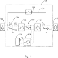
    • Fig. 1 shows a block diagram of a converter system according to an embodiment,
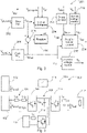
    • Fig. 2 shows a block diagram of a control unit according to an embodiment,
    • Fig. 3 shows a block diagram of the converter system according to a second embodiment,
    • Fig. 4 shows a block diagram of a control unit according to the second embodiment,
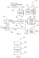
    • Fig. 5 shows a block diagram of an alternative control unit according to an embodiment,
    • Fig. 6 shows a flow diagram of a method according to the second embodiment.
    DETAILED DESCRIPTION OF EMBODIMENTS
  • Corresponding parts are provided with the same reference symbols in all figures.
  • Fig. 1 shows a block diagram of a converter system 100. The converter system comprises a rectifier 106 that is coupled on the input side to a power grid 102 and a filter 104 with inductances Lf1 and Lf2 and capacitor Cn. The converter system 100 further comprises a DC-link 108 and an inverter 110 such that the converter system 100 represents a double conversion system. The DC link is further coupled to a battery 114 through battery booster 116. The inverter output is coupled through output filter Lf, Cf to a critical load 112. A bypass 120 with bypass switch 118 may bypass the rectifier- converter chain 104, 106, 108, 110 and be connected to the power grid 102 on one end and to the critical load 112 on the other end. The converter system 100 may be a UPS, which shall provide reliably power to the critical load 112. For this, it has two mechanisms. The first mechanism is the bypass, which is disengaged, for example, when frequency fluctuations occur, and the other mechanism is retracting power from the battery, for example, when an outage on grid-side occurs. The mechanisms can work individually or in combination.
  • Fig. 2 shows a block diagram of a control unit 200 for controlling the converter system 100.
  • The circuit comprises a slow reference frame angle determination unit 202, here, a slow PLL 202 that provides a slow reference phase angle θR,slow to a virtual admittance 204. θR,slow is used to transform the voltage into a slow reference frame. The virtual admittance 204 receives Vpcc and the virtual source machine voltage Vvsm as input and acts as current source that outputs virtual source machine current Ivsm. Thus, the slow PLL 202 and the virtual admittance 204 form a grid-forming vector current control (GFVCC) system.
  • The control unit 200 further comprises a fast PLL 208 that provides a fast reference phase angle θR,fast to adder 218 that subtracts θR,fast from θR,slow. θR, fast is further used to transform the voltage into a fast reference frame. The result of the adder 218 is used to rotate Ivsm such that the reference current Ivsm,r for the rectifier virtual generator equivalent current reference is transformed into the fast PLL reference frame. As result, the reference current Ivsm,r is obtained. The rectifier current control unit 214 receives further currents such as Idroop and Idc,r, that may contribute to a total current, and θR,fast for generating or calculating the control voltage Vrect of the rectifier 106 for controlling the rectifier current. The part of the control unit 200 described above emulates the effect of a virtual synchronous generator operated in parallel with a virtual current source by means of the slow PLL 202 and the virtual admittance 204 that provides its output current Ivsm to the adder 218. The slow PLL 202 has a low bandwidth to match the virtual inertia effect of a synchronous machine such that it reacts slowly on grid angle and grid frequency changes. The fast PLL 208 has a high bandwidth that allows a fast grid frequency estimate and ensures the synchronization of the grid voltage with the inverter output voltage. The fast reference phase θR,fast is provided to the rectifier control unit 214 and to the inverter voltage control unit 216.
  • The individual blocks of the control unit 200 will be described in more detail in the following.
  • The slow PLL unit 202 and the virtual admittance block 204 are key components of the grid forming vector current control (GFVCC) algorithm. With special tuning rules for the gains of the slow PLL 202 and the virtual admittance block 104, the combination of both creates current references that are equivalent to the current of a virtual synchronous generator (VSM).
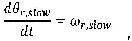
  • The slow PLL unit 202 generates a slow reference frame angle and a slow grid frequency estimate according to ω r , slow = K pll , p + K pll , i s V pcc , q , slow
    Figure imgb0001
    r , slow dt = ω r , slow ,
    Figure imgb0002
    and f slow = ω r , slow 2 π .
    Figure imgb0003
  • The slow PLL 202 gains are set according to K pll , p = K f MV pcc , K pll , i = c P V vsm MX v ,
    Figure imgb0004
    where M denotes the virtual inertia constant, Kf the damper winding constant, Xv = ωNLv the virtual reactance, Vvsm the amplitude of the back-emf (electromotive force) of the virtual generator and cp the power coefficient (cp = 3/2 in three-phase systems and peak vales). The specific tuning leads to a low bandwidth of the slow PLL 202 with rather low damping. Vpcc,d,slow and Vpcc,q,slow are calculated with the Park transformation using the slow reference frame angle θr,slow and the three phase quantities of the PCC voltage Vpcc,abc. Index d refers to the direct component of the Park transformed parameters, index q to the quadrature component, and index r to a reference parameter. The virtual admittance unit 204 is defined according to Y v = R v + s L v R v 2 + 2 L v R v s + L v 2 s 2 + ω N 2 ω N L v R v 2 + 2 L v R v s + L v 2 s 2 + ω N 2 ω N L v R v 2 + 2 L v R v s + L v 2 s 2 + ω N 2 R v + s L v R v 2 + 2 L v R v s + L v 2 s 2 + ω N 2
    Figure imgb0005
    where the index "v" is chosen for "virtual" and ωn is a nominal angle velocity, e.g. 2π 50 Hz. The virtual synchronous generator equivalent current references may be calculated as:
    • ivsm,d = Yv,dd (s) . (Vv - Vpcc,d,slow) + Yv,dq(s) . (-Vpcc,q,slow)
    • ivsm,q = Yv,qd(s) · (Vv - Vpcc,d,slow) + Yv,qq(s) · (-Vpcc,q,slow),
    where index dd is the first column and first row positon of the matrix Yv, etc.
  • The second, "fast PLL" 208 is running in parallel and calculates a fast reference frame angle and a fast grid frequency estimate according to ω r , fast = K pll , p , 2 + K pll , i , 2 s V pcc , q , fast
    Figure imgb0006
    r , fast dt = ω r , fast
    Figure imgb0007
    f fast = ω r , fast 2 π .
    Figure imgb0008
  • The PI controller gains of the fast PLL 208 may be chosen such that the bandwidth of the fast PLL is 2 to 10 times higher compared to the bandwidth of the slow PLL 202. Vpcc,d,fast and Vpcc,q,fast are calculated with the Park transformation using the fast reference frame angle θr,fast and the phase quantities of the PCC voltage Vpcc,abc. Before the virtual generator equivalent current references can be used in the fast PLL reference frame, they need to be rotated by the rotation unit 206 according to Δθ = θr , slow θr , fast
    Figure imgb0009
    ivsm , r , d = cos Δ θ ivsm , d sin Δ θ ivsm , q
    Figure imgb0010
    ivsm , r , q = cos Δ θ ivsm , q + sin Δ θ ivsm , d
    Figure imgb0011
  • Now, the additional active current reference components coming from the DC-link voltage control unit 212 and an optional frequency droop control unit 210 for frequency regulation can be added to current reference components from the virtual admittance 204. i d * = i vsm , r , d + i dc , r + i droop , r
    Figure imgb0012
    i q * = i vsm , r , q
    Figure imgb0013
  • The DC-link voltage control unit 212 typically is of PI-type and controls the DC -link voltage to its nominal value and creates an active power equivalent current reference idc,r. The droop control unit 210 typically is a P-type control block with piecewise linear characteristics. The input value is the measured grid frequency fslow, the output value is an active power equivalent current reference idroop,r. Due to the usage of the fast PLL reference frame, the DC -link voltage control and droop control current components are accurately aligned to the d-direction of the PCC voltage and therefore directly control active power flow. No reactive power is injected.
  • In a final step, the power injected by the virtual synchronous generator part 202, 204 of the rectifier control scheme could be used in a feedforward term for the battery booster current control P vsm , ff = 3 2 V pcc , d , slow i vsm , d + V pcc , q , slow i vsm , q
    Figure imgb0014
  • Alternatively, the quantities in the fast reference frame can be used P vsm , ff = 3 2 V pcc , d , fast i vsm , r , d + V pcc , q , fast i vsm , r , q
    Figure imgb0015
  • If the optional droop control unit 210 is required, additionally the corresponding equivalent power should be considered as well in the feedforward term for the battery booster 116 P vsm , ff = 3 2 V pcc , d , fast i vsm , r , d + i droop , r + V pcc , q , fast i vsm , r , q
    Figure imgb0016
  • The reference for the battery booster current is calculated as i batt , ff = P vsm , ff V batt
    Figure imgb0017
  • Typically, the controller for the battery booster 116 is of PI-type and controls the battery current to follow a given reference.
  • Finally, the inverter output voltage control unit 216 is described. In general, it will control the output voltage Vout to follow a given reference: V out , d * = V N
    Figure imgb0018
    V out , q * = 0
    Figure imgb0019
    θ = θr,fast
    The references for the phase quantities Vout,abc are calculated with the inverse Park transformation using the references in dq-reference frame and the fast PLL angle θr,fast. By doing so, accurate synchronization of the inverter output voltage with the grid input voltage is ensured. The phase difference is minimized, and the bypass switch 118 can be operated safely in steady-state as well as in transient situations.
  • The rectifier current control unit 214 as well as the inverter output voltage control unit 216 can be implemented with any control method (PID / PI / P classic control, cascaded-control, state-feedback control, model-predictive control) and in any reference frame (synchronous reference frame (dq), stationary reference frame (αβ), stationary phase-oriented reference frame (abc)). The invention described in this document is not restricting the type of control.
  • Fig. 3 shows a block diagram of a double-conversion UPS system with dual-infeed. Some UPS systems are configured with a double infeed structure. The bypass switch 118 is connected to a separate grid connection, e.g. an individual transformer or a second AC voltage bus with individual protection for redundancy reasons. In this case, the output voltage of the inverter stage has to be controlled to be in phase with the voltage of the second infeed 122. The proposed control solution is therefore adapted accordingly.
  • Fig. 4 shows a schematic block diagram of a proposed control solution for dual-infeed UPS systems. The tuning of the control scheme for the rectifier 106 is the same as described above. However, the inverter output voltage is controlled with the angle determined with "Fast PLL 2" 220 such that the inverter output voltage is synchronized with the second infeed 122.
  • Another approach is to use a fast PLL 208 and a second order filter 222 on the estimated grid angle according to Figure 5. The second order filter 222 is parametrized as follows θ r , slow = 1 K 1 s 2 1 K 1 s 2 + K 2 s + 1 θ r , fast
    Figure imgb0020
  • Assuming the fast PLL 208 can track the grid voltage angle immediately, the parameters K1 and K2 can be selected to achieve equivalency with the inertia effect of the original slow PLL 202. K 1 = V pcc K pll , i = c P V pcc V vsm MX v ,
    Figure imgb0021
    K 2 = K pll , p K pll , i = K f X v c p V pcc V vsm
    Figure imgb0022
  • Subsequently, the grid voltage estimate 224 used for the virtual admittance 204 is reconstructed with the difference Δθ of the filtered angle θr,slow and the fast angle θr,fast according to Δθ = θr , slow θr , fastV pcc , d , slow = 1 1 2 Δ θ 2
    Figure imgb0023
    Vpcc,q,slow =- Δθ 2
  • It is assumed that the grid voltage amplitude is constant, only grid voltage angle shifts will be detected. In the steady-state, no reactive power will be injected because grid voltage amplitude changes are not detected. This might be beneficial in certain applications, such as grid connected UPS.
  • Fig. 6 shows a block diagram of a method 600 for controlling the converter system 100 comprising the following steps: In a first step 602, a fast reference frame angle θr,fast representing an angle that is fast following a grid phase deviation is generated. In a second step 604, a slow reference frame angle θr,slow representing an angle that is slowly following a grid phase deviation is generated. In a third step 606, the slow reference frame angle θr,slow and the fast reference frame angle θr,fast are used to control the rectifier output current, and the fast reference frame angle θr,fast are used to control the inverter output voltage and to synchronize the inverter output voltage with the grid voltage.
  • Therefore, a combination of grid-forming vector current control with a second, fast PLL 208 and reference frame transformations is provided.
  • Other variations to the disclosed embodiments can be understood and effected by those skilled in the art in practicing the claimed invention, from the study of the drawings, the disclosure, and the appended claims. In the claims, the word "comprising" does not exclude other elements or steps and the indefinite article "a" or "an" does not exclude a plurality. A single processor or other unit may fulfill the functions of several items or steps recited in the claims. The mere fact that certain measures are recited in mutually different dependent claims does not indicate that a combination of these measures cannot be used to advantage. A computer program may be stored/distributed on a suitable medium such as an optical storage medium or a solid-state medium supplied together with or as part of other hardware, but may also be distributed in other forms, such as via the Internet or other wired or wireless telecommunication systems. Any reference signs in the claims should not be construed as limiting the scope of the claims.
  • List of reference numerals
  • 100
    converter system
    102
    power grid
    104
    filter
    106
    rectifier
    108
    DC-link
    110
    inverter
    112
    critical load
    114
    battery
    116
    battery booster
    118
    bypass switch
    120
    bypass
    122
    second infeed
    200
    control unit
    202
    slow reference frame angle determination unit; slow PLL
    204
    virtual admittance
    206
    rotation unit
    208
    (first) fast PLL
    210
    droop control unit
    212
    DC-link voltage control unit
    214
    rectifier current control unit
    216
    inverter output voltage control unit
    218
    adder
    220
    second fast PLL
    222
    filter
    224
    Vpcc dq slow estimate block
    600
    method for controlling the converter system
    602
    first step of the method
    604
    second step of the method
    606
    third step of the method

Claims (15)

  1. Converter system (100) comprising
    a rectifier (106) configured to receive a grid voltage,
    a DC link stage (108) configured to receive an output voltage of the rectifier (106) and to provide a DC link voltage for an inverter (110), and
    the inverter (110) configured to receive the DC link voltage from the DC link stage (108), and to generate an output voltage, wherein the rectifier (106), the DC link stage (108) and the inverter (110) are connected in series;
    a control unit (200) comprising
    a slow reference frame angle determination unit (202), configured to generate a slow reference frame angle θr,slow representing an angle that is slowly following a grid phase deviation; and
    a fast Phase Locked Loop, PLL (208), configured to generate a fast reference frame angle θr,fast representing an angle that is fast following a grid phase deviation;
    wherein the control unit (200) is further configured to
    use the slow reference frame angle θr,slow and the fast reference frame angle θr,fast to control the rectifier output current, and to
    use the fast reference frame angle θr,fast to control the inverter output voltage and to synchronize the inverter output voltage with the grid voltage.
  2. Converter system (100) according to claim 1, wherein the slow reference frame angle determination unit (202) is
    a slow PLL (202), wherein the slow PLL (202) has a smaller bandwidth than the fast PLL (208).
  3. Converter system (100) according to claim 1, wherein the slow reference frame angle determination unit (202) is configured to derivate the slow reference frame angle θr,slow from the fast reference frame angle θr,fast.
  4. Converter system (100) according to any of claims 1 to 3, wherein the control unit (200) is configured
    to transform the grid voltage Vpcc into a slow reference frame voltage Vpcc slow, wherein the transformation is a Park transformation using the slow reference frame angle θr,slow; and
    to transform the grid voltage Vpcc into a fast reference frame voltage Vpcc fast, wherein the transformation is a Park transformation using the fast reference frame angle θr,fast; and wherein
    the slow reference frame voltage Vpcc slow is used to calculate a virtual synchronous machine reference current IVSM,r wherein the virtual synchronous machine reference current IVSM,r is a further component for controlling rectifier output current; and
    the fast reference frame voltage Vpcc fast is a further component for controlling the inverter output voltage.
  5. Converter system (100) according to claim 4, wherein the virtual synchronous machine reference current IVSM,r is obtained by applying a virtual admittance to the slow reference frame voltage Vpcc slow resulting in a virtual synchronous machine current IVSM and by rotating the virtual synchronous machine current IVSM by an angle difference between θr,slow and θr,fast.
  6. Converter system (100) according to any of the previous claims, comprising further an inverter voltage control unit (200) configured to calculate an output voltage Vinv for controlling the inverter output voltage, wherein the output voltage Vinv is controlled to an input reference voltage Vref and to the reference frame angle θr,fast.
  7. Converter system (100) according to claim 6, wherein the inverter voltage control unit (200) is further configured to perform the inverse Park transformation of the inverter output voltage Vinv using the fast reference frame angle θr,fast.
  8. Converter system (100) according to any one of the previous claims, wherein the slow reference frame angle determination unit (202) is further configured to output a slow frequency fslow being the time derivate of θr,slow, and wherein the converter system (100) further comprises a droop control unit (200) configured to generate a current Idroop from fslow and θr,slow, and Idroop is an additional input current component to generate the output voltage Vrect for controlling the rectifier current.
  9. Converter system (100) according to any of the previous claims, wherein the control unit (200) further comprises a DC link voltage control unit (200) configured to generate a current Idc_r from the DC link voltage Vdc, and Idc_r is an additional input current component to generate the output voltage Vrect for controlling the rectifier current.
  10. Converter system (100) according to any one of the previous claims, wherein the converter system (100) further comprises a switchable bypass (120), wherein a first end of the bypass (120) is connected to a second first and a second end of the bypass (120) is connected to a load, and the rectifier is connected to the first infeed, and the first infeed is a power grid infeed.
  11. Converter system (100) according to any one of claims 1 to 9, wherein the converter system (100) further comprises a switchable bypass (120);
    wherein the bypass (120) is connected to a second infeed and a second end of the bypass (120) is connected at a common connection point to a load;
    wherein the rectifier (106), the DC link (108) and the inverter (110) are connected to the first infeed on one end and to the load at the common connection point at a second end;
    wherein the converter system (100) comprises a further fast PLL (220);
    wherein the slow reference frame angle determination unit (202) and the fast PLL (208) are connected to the first infeed and used for controlling the rectifier current; and
    wherein the further fast PLL (220) is connected to the second infeed and used for controlling the inverter voltage.
  12. Converter system (100) according to any one of claims 4 to 11, further comprising a DC source (114) and a DC source booster (116), wherein the control unit (200) is further configured to provide a DC source booster reference current ibatt,ff by determining a virtual synchronous machine feedforward power based on the virtual synchronous machine reference current IVSM,r and slow reference frame voltage Vpcc slow and Vbatt.
  13. Converter system (100) according to any one of the previous claims, wherein the converter system (100) is an uninterruptable power supply, UPS, system.
  14. Control unit (200) for a converter system (100) according to any of claims 1 to 13.
  15. Usage of a control unit (200) according to claim 14 in an uninterruptable power supply system.
EP21180063.6A 2021-06-17 2021-06-17 Converter system Pending EP4106174A1 (en)

Priority Applications (2)

Application Number Priority Date Filing Date Title
EP21180063.6A EP4106174A1 (en) 2021-06-17 2021-06-17 Converter system
US17/840,790 US12074531B2 (en) 2021-06-17 2022-06-15 Converter system

Applications Claiming Priority (1)

Application Number Priority Date Filing Date Title
EP21180063.6A EP4106174A1 (en) 2021-06-17 2021-06-17 Converter system

Publications (1)

Publication Number Publication Date
EP4106174A1 true EP4106174A1 (en) 2022-12-21

Family

ID=76522784

Family Applications (1)

Application Number Title Priority Date Filing Date
EP21180063.6A Pending EP4106174A1 (en) 2021-06-17 2021-06-17 Converter system

Country Status (2)

Country Link
US (1) US12074531B2 (en)
EP (1) EP4106174A1 (en)

Citations (1)

* Cited by examiner, † Cited by third party
Publication number Priority date Publication date Assignee Title
EP3832829A1 (en) * 2019-12-02 2021-06-09 ABB Schweiz AG Grid forming vector current control

Family Cites Families (7)

* Cited by examiner, † Cited by third party
Publication number Priority date Publication date Assignee Title
US8432052B2 (en) * 2010-05-27 2013-04-30 Rockwell Automation Technologies, Inc. Wind power converter system with grid side reactive power control
ES2402465B1 (en) 2011-02-28 2014-01-27 Abengoa Solar New Technologies S.A. VIRTUAL ADMITTANCE CONTROLLER BASED ON STATIC POWER CONVERTERS.
EP2955808B1 (en) * 2014-06-13 2018-08-08 Nordex Energy GmbH Method for controlling a wind energy turbine during an asymmetric network fault
WO2017036517A1 (en) 2015-09-01 2017-03-09 Abb Schweiz Ag Voltage source converter (vsc) control system with active damping
WO2017125067A1 (en) 2016-01-22 2017-07-27 The University Of Hong Kong Power supply supporting virtual inertia for grid control (micro-spring converter)
EP3376627B1 (en) 2017-03-14 2021-04-28 ABB Schweiz AG Method and control system for controlling a power converter
EP3836337A1 (en) * 2019-12-10 2021-06-16 Wobben Properties GmbH Procedure for current limiting of a virtual synchronous machine, in particular during a mains fault

Patent Citations (1)

* Cited by examiner, † Cited by third party
Publication number Priority date Publication date Assignee Title
EP3832829A1 (en) * 2019-12-02 2021-06-09 ABB Schweiz AG Grid forming vector current control

Non-Patent Citations (2)

* Cited by examiner, † Cited by third party
Title
KEYAN SHI ET AL: "Unified control scheme design for both the PWM rectifier and the inverter in the uninterruptible power supply (UPS) system", 2017 IEEE 3RD INTERNATIONAL FUTURE ENERGY ELECTRONICS CONFERENCE AND ECCE ASIA (IFEEC 2017 - ECCE ASIA), IEEE, 3 June 2017 (2017-06-03), pages 1462 - 1467, XP033129736, DOI: 10.1109/IFEEC.2017.7992260 *
ROASTO INDREK ET AL: "Multiport Interface Converter with an Energy Storage for Nanogrids", IECON 2018 - 44TH ANNUAL CONFERENCE OF THE IEEE INDUSTRIAL ELECTRONICS SOCIETY, IEEE, 21 October 2018 (2018-10-21), pages 6088 - 6093, XP033483845, [retrieved on 20181226], DOI: 10.1109/IECON.2018.8591104 *

Also Published As

Publication number Publication date
US12074531B2 (en) 2024-08-27
US20220407430A1 (en) 2022-12-22

Similar Documents

Publication Publication Date Title
Awal et al. Double synchronous unified virtual oscillator control for asymmetrical fault ride-through in grid-forming voltage source converters
Lee et al. A master and slave control strategy for parallel operation of three-phase UPS systems with different ratings
CN102299659B (en) For system and the method for the control of multiphase power converter
Şerban et al. Aggregate load-frequency control of a wind-hydro autonomous microgrid
Gkavanoudis et al. Fault ride-through capability of a DFIG in isolated grids employing DVR and supercapacitor energy storage
WO2022269811A1 (en) Control device and power conversion device
Ji et al. Enhancement of low-voltage ride-through capability for virtual synchronous generators based on virtual impedance voltage control
Fan et al. Transient algebraic impedance derivations and applications for PLL-synchronized IBRs
Pal et al. Fault-induced current limitation control for grid-forming inverters: A framework for rapid grid code compliance
US12074531B2 (en) Converter system
EP4106179A1 (en) Grid forming operation with a wound rotor induction generator
Alcala et al. A three-phase back-to-back converter for reactive power compensation, current harmonic filtering and active power compensation
Islam et al. Controller design for grid forming inverter-based power generating systems to behave as synchronous machines
Jeong et al. High-performance control of three-phase four-wire DVR systems using feedback linearization
Sahoo et al. A novel communication-less frequency restoration technique in droop controlled inverter-based islanded ac microgrid
Naeem et al. A robust auto-synchronizer for synchronverter
Abbassi SOGI-based Flexible Grid Connection of PV Power Three Phase Converters under Non-ideal Grid Conditions.
Miranbeigi et al. A new representation based on virtual capacitor for virtual synchronous generators
Naeem et al. A PLL-less fourier analysis based self-synchronizer for synchronverter having uninterrupted power supply capability
Hariharan et al. An inbuilt synchronization controller for three-phase synchronverters
Attuati et al. Sliding mode current control of DSTATCOM applied to voltage regulation of induction generator based systems
Eren et al. Modifying the three-phase synchronous reference frame phase-locked loop to remove unbalance and harmonic errors
Sadeque Restoration and universal operation of grid-forming inverters
Choudhury et al. Frequency Stability and Fast Frequency Response in Hybrid AC-DC Transmission Grids: A Comparative Study of EMT and RMS Modelling Approaches
Alharbi et al. Power Ripple Control Method for Modular Multilevel Converter under Grid Imbalances. Energies 2022, 15, 3535

Legal Events

Date Code Title Description
PUAI Public reference made under article 153(3) epc to a published international application that has entered the european phase

Free format text: ORIGINAL CODE: 0009012

STAA Information on the status of an ep patent application or granted ep patent

Free format text: STATUS: THE APPLICATION HAS BEEN PUBLISHED

AK Designated contracting states

Kind code of ref document: A1

Designated state(s): AL AT BE BG CH CY CZ DE DK EE ES FI FR GB GR HR HU IE IS IT LI LT LU LV MC MK MT NL NO PL PT RO RS SE SI SK SM TR

STAA Information on the status of an ep patent application or granted ep patent

Free format text: STATUS: REQUEST FOR EXAMINATION WAS MADE

17P Request for examination filed

Effective date: 20230620

RBV Designated contracting states (corrected)

Designated state(s): AL AT BE BG CH CY CZ DE DK EE ES FI FR GB GR HR HU IE IS IT LI LT LU LV MC MK MT NL NO PL PT RO RS SE SI SK SM TR

STAA Information on the status of an ep patent application or granted ep patent

Free format text: STATUS: EXAMINATION IS IN PROGRESS

17Q First examination report despatched

Effective date: 20250709