EP4106159A1 - Health monitoring of multi-slice hinge line actuators - Google Patents
Health monitoring of multi-slice hinge line actuators Download PDFInfo
- Publication number
- EP4106159A1 EP4106159A1 EP21275087.1A EP21275087A EP4106159A1 EP 4106159 A1 EP4106159 A1 EP 4106159A1 EP 21275087 A EP21275087 A EP 21275087A EP 4106159 A1 EP4106159 A1 EP 4106159A1
- Authority
- EP
- European Patent Office
- Prior art keywords
- actuator
- strain
- slices
- slice
- strain gauge
- Prior art date
- Legal status (The legal status is an assumption and is not a legal conclusion. Google has not performed a legal analysis and makes no representation as to the accuracy of the status listed.)
- Granted
Links
Images


Classifications
-
- G—PHYSICS
- G01—MEASURING; TESTING
- G01M—TESTING STATIC OR DYNAMIC BALANCE OF MACHINES OR STRUCTURES; TESTING OF STRUCTURES OR APPARATUS, NOT OTHERWISE PROVIDED FOR
- G01M13/00—Testing of machine parts
-
- B—PERFORMING OPERATIONS; TRANSPORTING
- B64—AIRCRAFT; AVIATION; COSMONAUTICS
- B64C—AEROPLANES; HELICOPTERS
- B64C13/00—Control systems or transmitting systems for actuating flying-control surfaces, lift-increasing flaps, air brakes, or spoilers
- B64C13/24—Transmitting means
- B64C13/38—Transmitting means with power amplification
- B64C13/50—Transmitting means with power amplification using electrical energy
-
- B—PERFORMING OPERATIONS; TRANSPORTING
- B64—AIRCRAFT; AVIATION; COSMONAUTICS
- B64C—AEROPLANES; HELICOPTERS
- B64C13/00—Control systems or transmitting systems for actuating flying-control surfaces, lift-increasing flaps, air brakes, or spoilers
- B64C13/24—Transmitting means
- B64C13/26—Transmitting means without power amplification or where power amplification is irrelevant
- B64C13/28—Transmitting means without power amplification or where power amplification is irrelevant mechanical
-
- B—PERFORMING OPERATIONS; TRANSPORTING
- B64—AIRCRAFT; AVIATION; COSMONAUTICS
- B64F—GROUND OR AIRCRAFT-CARRIER-DECK INSTALLATIONS SPECIALLY ADAPTED FOR USE IN CONNECTION WITH AIRCRAFT; DESIGNING, MANUFACTURING, ASSEMBLING, CLEANING, MAINTAINING OR REPAIRING AIRCRAFT, NOT OTHERWISE PROVIDED FOR; HANDLING, TRANSPORTING, TESTING OR INSPECTING AIRCRAFT COMPONENTS, NOT OTHERWISE PROVIDED FOR
- B64F5/00—Designing, manufacturing, assembling, cleaning, maintaining or repairing aircraft, not otherwise provided for; Handling, transporting, testing or inspecting aircraft components, not otherwise provided for
- B64F5/60—Testing or inspecting aircraft components or systems
-
- F—MECHANICAL ENGINEERING; LIGHTING; HEATING; WEAPONS; BLASTING
- F16—ENGINEERING ELEMENTS AND UNITS; GENERAL MEASURES FOR PRODUCING AND MAINTAINING EFFECTIVE FUNCTIONING OF MACHINES OR INSTALLATIONS; THERMAL INSULATION IN GENERAL
- F16H—GEARING
- F16H21/00—Gearings comprising primarily only links or levers, with or without slides
- F16H21/10—Gearings comprising primarily only links or levers, with or without slides all movement being in, or parallel to, a single plane
- F16H21/40—Gearings comprising primarily only links or levers, with or without slides all movement being in, or parallel to, a single plane for interconverting rotary motion and oscillating motion
-
- G—PHYSICS
- G01—MEASURING; TESTING
- G01L—MEASURING FORCE, STRESS, TORQUE, WORK, MECHANICAL POWER, MECHANICAL EFFICIENCY, OR FLUID PRESSURE
- G01L1/00—Measuring force or stress, in general
- G01L1/20—Measuring force or stress, in general by measuring variations in ohmic resistance of solid materials or of electrically-conductive fluids; by making use of electrokinetic cells, i.e. liquid-containing cells wherein an electrical potential is produced or varied upon the application of stress
- G01L1/205—Measuring force or stress, in general by measuring variations in ohmic resistance of solid materials or of electrically-conductive fluids; by making use of electrokinetic cells, i.e. liquid-containing cells wherein an electrical potential is produced or varied upon the application of stress using distributed sensing elements
-
- G—PHYSICS
- G01—MEASURING; TESTING
- G01L—MEASURING FORCE, STRESS, TORQUE, WORK, MECHANICAL POWER, MECHANICAL EFFICIENCY, OR FLUID PRESSURE
- G01L1/00—Measuring force or stress, in general
- G01L1/24—Measuring force or stress, in general by measuring variations of optical properties of material when it is stressed, e.g. by photoelastic stress analysis using infrared, visible light, ultraviolet
- G01L1/242—Measuring force or stress, in general by measuring variations of optical properties of material when it is stressed, e.g. by photoelastic stress analysis using infrared, visible light, ultraviolet the material being an optical fibre
- G01L1/246—Measuring force or stress, in general by measuring variations of optical properties of material when it is stressed, e.g. by photoelastic stress analysis using infrared, visible light, ultraviolet the material being an optical fibre using integrated gratings, e.g. Bragg gratings
-
- H—ELECTRICITY
- H02—GENERATION; CONVERSION OR DISTRIBUTION OF ELECTRIC POWER
- H02K—DYNAMO-ELECTRIC MACHINES
- H02K11/00—Structural association of dynamo-electric machines with electric components or with devices for shielding, monitoring or protection
- H02K11/20—Structural association of dynamo-electric machines with electric components or with devices for shielding, monitoring or protection for measuring, monitoring, testing, protecting or switching
-
- H—ELECTRICITY
- H02—GENERATION; CONVERSION OR DISTRIBUTION OF ELECTRIC POWER
- H02K—DYNAMO-ELECTRIC MACHINES
- H02K11/00—Structural association of dynamo-electric machines with electric components or with devices for shielding, monitoring or protection
- H02K11/20—Structural association of dynamo-electric machines with electric components or with devices for shielding, monitoring or protection for measuring, monitoring, testing, protecting or switching
- H02K11/24—Devices for sensing torque, or actuated thereby
-
- H—ELECTRICITY
- H02—GENERATION; CONVERSION OR DISTRIBUTION OF ELECTRIC POWER
- H02K—DYNAMO-ELECTRIC MACHINES
- H02K16/00—Machines with more than one rotor or stator
-
- H—ELECTRICITY
- H02—GENERATION; CONVERSION OR DISTRIBUTION OF ELECTRIC POWER
- H02K—DYNAMO-ELECTRIC MACHINES
- H02K41/00—Propulsion systems in which a rigid body is moved along a path due to dynamo-electric interaction between the body and a magnetic field travelling along the path
- H02K41/02—Linear motors; Sectional motors
-
- B—PERFORMING OPERATIONS; TRANSPORTING
- B64—AIRCRAFT; AVIATION; COSMONAUTICS
- B64D—EQUIPMENT FOR FITTING IN OR TO AIRCRAFT; FLIGHT SUITS; PARACHUTES; ARRANGEMENT OR MOUNTING OF POWER PLANTS OR PROPULSION TRANSMISSIONS IN AIRCRAFT
- B64D45/00—Aircraft indicators or protectors not otherwise provided for
- B64D2045/0085—Devices for aircraft health monitoring, e.g. monitoring flutter or vibration
-
- H—ELECTRICITY
- H02—GENERATION; CONVERSION OR DISTRIBUTION OF ELECTRIC POWER
- H02K—DYNAMO-ELECTRIC MACHINES
- H02K2213/00—Specific aspects, not otherwise provided for and not covered by codes H02K2201/00 - H02K2211/00
- H02K2213/06—Machines characterised by the presence of fail safe, back up, redundant or other similar emergency arrangements
-
- H—ELECTRICITY
- H02—GENERATION; CONVERSION OR DISTRIBUTION OF ELECTRIC POWER
- H02K—DYNAMO-ELECTRIC MACHINES
- H02K2213/00—Specific aspects, not otherwise provided for and not covered by codes H02K2201/00 - H02K2211/00
- H02K2213/12—Machines characterised by the modularity of some components
Definitions
- the present disclosure relates to multi-slice hinge line actuators such as for aircraft wings, and for arrangements for monitoring the health of such actuators.
- Actuators are used in many areas where components or surfaces are to be moved. Actuators may be mechanical, hydraulic, electric, electromechanical, electrohydraulic etc. Actuators of various types are used to move aircraft surfaces such as doors, flaps, slats, panels, etc., whether these are flight control surfaces or other panels.
- Hinge-line actuators have been developed to enable the movement of flight control surfaces.
- These hinge-line rotary mechanical actuators are in the form of a hinge structure having a rotational axis for the hinge, with this rotational axis aligned with that of the movable flight control surface so that the actuator acts as a hinge that allows angular rotation of the flight control surface.
- Hinge-line actuators can be designed for other applications, even other than in aircraft, where a surface or part is to be moved by rotation about an axis.
- multi-slice hinge-line actuators have been developed such as described in US 2016/0152322 .
- These actuators comprises a number of layers or slices coupled to a common input shaft motor stator that rotates about a rotational axis. Each slice is configured to rotate about the axis.
- the slices are attached to the movable surface and act together to cause the surface to rotate.
- the individual slices share the load substantially equally.
- multi-slice hinge-line actuator comprising: a plurality of actuator slices mounted around a common axis of rotation and arranged to be rotated around the axis of rotation by a drive means in response to a control signal, the slices spaced axially along the axis of rotation; each actuator slice having a first attachment means for attachment to a relatively fixed structure and a second attachment means for attachment to a moveable structure to be moved by the actuator in response to the control signal; and means for monitoring a strain pattern in the actuator at a plurality of locations along the axial direction of the actuator.
- the first attachment means may comprise one or more mounting pins extending axially and connecting the plurality of slices.
- the means for monitoring the strain pattern may be mounted in or on one or more of the one or more mounting pins.
- the means for monitoring the strain pattern may comprise a strain gauge e.g. an electrical strain gauge or an optical strain gauge with multiple Fiber Bragg gratings.
- the multi-slice actuator 10 such as shown in Fig. 1 , is designed by be arranged in the line of rotation of the part or surface to be moved like a hinge and is controlled in response to receiving a control signal from a controller (not shown).
- the actuator defines a rotational axis 12 that is, in use, aligned with the axis of rotation of the movable surface (not shown).
- One side 14 of the actuator is arranged to be fixed to a fixed structure (e.g. the non-movable part of the aircraft wing).
- the actuator comprises a number of actuator slices 20 spaced axially along the length of the axis and that rotate about the axis.
- Each of the multiple slices 20 along the length of the actuator defines a slice arm 22 arranged to be mounted, in use, to the surface or panel to be controlled (not shown).
- the attachment may be by means of a bolt or pin 24 that passes through eyelets 26 in each of the slice arms 22 and the bolt is fastened to the movable surface.
- Other means of attaching the slices to the movable surface may also be used.
- the actuator can be controlled responsive to a signal from the controller so that the slice arms rotate and control the angle of the movable surface to which they are attached.
- the structure and general operation of the multi-slice hinge-line actuator is generally known and will not be described further in this disclosure.
- the objective of the present disclosure is to provide an assembly whereby the health of the slices of the actuator can be monitored and an indication can be provided if one or more of the slices ceases to perform properly, thus not taking up its share, or its full share of the load.
- means are provided to monitor the strain pattern along the length direction of the actuator in the load paths between the fixed structure and the actuator to determine changes in the pattern of the strain distributed between the slices.
- the pattern will provide an indication of how the load is shared between the slices.
- a change in the strain distribution is indicative of one or more of the slices taking more or less of the load and can, therefore, be used to determine that one or more of the slices has become damaged or defective.
- the strain pattern can be measured or monitored in different ways and the way in which the strain pattern is monitored is not limiting on the disclosure.
- the strain can be measured at multiple points, A, B, C, D, E, along the mounting pin or rod 24 - i.e. where the actuator is fixed to the aircraft structure or the like.
- the mounting pin 24 is attached to all of the slices 20 e.g. by passing through an opening in each slice arm as shown in Fig. 2 and so extends along the axial length of the actuator.
- the mounting pin therefore provides part of the load path between the multiple slices.
- a means for measuring the strain at multiple points A,B,C,D,E, along the pin is provided (described further below).
- a change in the strain pattern between the multiple points is indicative of a change in the distribution of load between the slices 20.
- the change in strain can be determined by monitoring absolute strain levels at the multiple points and comparing them to a predetermined threshold level.
- the actual strain on the pin along its length may, however, vary due to normal operating conditions such as aircraft flight conditions and so it may be preferable to monitor changes in the strain distribution rather than absolute levels or values.
- two mounting pins - an upper mounting pin 24a and a lower mounting pin 24b may be provided.
- the strain measurement points may be provided on a single pin as shown in Fig. 3B or, if, for example, there is a space restriction as to the number of strain measurement points that can be located on a single pin (e.g. because of the size of the strain measuring device being used), the measurement points may be shared across both pins.
- the actual number and location of strain measurement points may vary depending on the application of the actuator and on factors such as the load sharing pattern between slices, the stiffness of the actuator and structure, the loading on the movable part etc.
- strain measurement points could be provided on different parts of the actuator along its length or additional components could be added to the actuator on which to mount the strain measuring devices.
- the present disclosure is not limited to any particular device or method for measuring strain.
- One example may be to use an electrical strain gauge such as shown in Fig. 4 .
- Such strain gauges can be mounted into pins or hollow bodies so as to protect the components and wiring.
- Such strain gauges could, therefore, be provided inside the mounting pin(s) 24 or could be attached to the mounting pin(s) along the axial length at the strain measurement points.
- multiple Fibre Bragg Gratings 30 could be provided onto a single fibre optic cable 40 which can then be mounted inside or along the load pin(s) or at another location extending along the axial length of the actuator. The refraction pattern can then be observed, based on the Bragg grating pattern, at multiple locations X, Y, Z, to monitor the strain pattern along the length of the actuator.
- An optical strain gauge may also have the advantage that signals from several actuators can be combined and transmitted along a single cable, to a central controller (not shown).
- Measurement of the strain pattern along the actuator length may also be realised in other ways known to the skilled person.
Landscapes
- Engineering & Computer Science (AREA)
- Physics & Mathematics (AREA)
- Power Engineering (AREA)
- General Physics & Mathematics (AREA)
- Aviation & Aerospace Engineering (AREA)
- Mechanical Engineering (AREA)
- General Engineering & Computer Science (AREA)
- Automation & Control Theory (AREA)
- Microelectronics & Electronic Packaging (AREA)
- Electromagnetism (AREA)
- Manufacturing & Machinery (AREA)
- Transportation (AREA)
- Combustion & Propulsion (AREA)
- Chemical & Material Sciences (AREA)
- Testing Of Devices, Machine Parts, Or Other Structures Thereof (AREA)
- Aerodynamic Tests, Hydrodynamic Tests, Wind Tunnels, And Water Tanks (AREA)
- Structures Of Non-Positive Displacement Pumps (AREA)
Abstract
Description
- The present disclosure relates to multi-slice hinge line actuators such as for aircraft wings, and for arrangements for monitoring the health of such actuators.
- Actuators are used in many areas where components or surfaces are to be moved. Actuators may be mechanical, hydraulic, electric, electromechanical, electrohydraulic etc. Actuators of various types are used to move aircraft surfaces such as doors, flaps, slats, panels, etc., whether these are flight control surfaces or other panels.
- In some fields, special consideration needs to be given to the location of the actuator and its size and or weight. This is the case, for example, where actuators are used in aircraft where it is important to minimise the size and weight of parts whilst maintaining reliability. Actuator designs have been developed to provide effective movement of flight control surfaces along the length of an aircraft wing. Hinge-line actuators have been developed to enable the movement of flight control surfaces. These hinge-line rotary mechanical actuators are in the form of a hinge structure having a rotational axis for the hinge, with this rotational axis aligned with that of the movable flight control surface so that the actuator acts as a hinge that allows angular rotation of the flight control surface. Hinge-line actuators can be designed for other applications, even other than in aircraft, where a surface or part is to be moved by rotation about an axis.
- When designing an aircraft flight control system, consideration must be given to the potential failure modes of the actuators used. Internal component failures can cause the actuator to become jammed or disconnected, that is the mechanical load path from the input of the actuator to the output at the surface is lost. Such problems can arise in all other applications where hinge-line actuators are used. Also, where space is limited e.g. in thin-wing aircraft, there is insufficient space in the wing to have a single actuator that can withstand the total loading on the flight control surface it is attached to.
- More recently, so-called multi-slice hinge-line actuators have been developed such as described in
US 2016/0152322 . These actuators comprises a number of layers or slices coupled to a common input shaft motor stator that rotates about a rotational axis. Each slice is configured to rotate about the axis. The slices are attached to the movable surface and act together to cause the surface to rotate. The individual slices share the load substantially equally. - With such multi-slice actuators, if one of the slices is damaged such that that slice is no longer effective in taking or transferring part of the load, the load for that slice will be distributed amongst the other slices. Whilst this ensures that the necessary load continues to be transferred to the movable surface, it does mean that the remaining working slices will be subjected to higher loads than expected which can result in too much stress on those slices and lead to failure of the actuator.
- Because the load is distributed between all slices even when one or more slices fails, it is not immediately apparent that a slice has failed because the actuator will continue to move the surface as required. The failure of one or more slices might therefore only become apparent during maintenance checks while the aircraft is on the ground or, more of a problem, if the entire actuator fails because the working slices have been subject to too much stress and also fail. This is, at least, costly and time intensive to repair, but can also be hazardous if failure occurs during flight.
- There is, therefore, a need to monitor the health of all slices of a multi-slice hinge-line actuator.
- According to the present disclosure, there is provided multi-slice hinge-line actuator comprising: a plurality of actuator slices mounted around a common axis of rotation and arranged to be rotated around the axis of rotation by a drive means in response to a control signal, the slices spaced axially along the axis of rotation; each actuator slice having a first attachment means for attachment to a relatively fixed structure and a second attachment means for attachment to a moveable structure to be moved by the actuator in response to the control signal; and means for monitoring a strain pattern in the actuator at a plurality of locations along the axial direction of the actuator.
- The first attachment means may comprise one or more mounting pins extending axially and connecting the plurality of slices. The means for monitoring the strain pattern may be mounted in or on one or more of the one or more mounting pins.
- The means for monitoring the strain pattern may comprise a strain gauge e.g. an electrical strain gauge or an optical strain gauge with multiple Fiber Bragg gratings.
- Also provided, is a method of monitoring a multi-slice hinge-line actuator, comprising monitoring a strain pattern at a plurality of locations along the axial direction of the actuator and determining whether one or more slices of the actuator has become defective based on the strain pattern.
- Embodiments of the disclosure will now be described by way of example only, with reference to the drawings. Although described in the context of a multi-slice hinge-line actuator for use in moving aircraft panels and surfaces e.g. wing panels, it should be understood that the apparatus and method of the disclosure are applicable to multi-slice actuators for other uses.
-
Figure 1 shows a perspective view of a typical multi-slice hinge-line actuator into which the assembly of the present disclosure can be incorporated. -
Figure 2 shows an example of a multi-slice hinge-line actuator modified according to the present disclosure. -
Figures 3A and 3B show alternative examples using the principles of the present disclosure. -
Figure 4 shows a possible embodiment of a strain gauge for use in the assembly of the disclosure. -
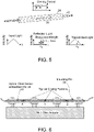
Figure 5 shows the principle of an alternative strain measuring concept for use in the assembly of the disclosure. -
Figure 6 shows an alternative embodiment using the principles of the present disclosure. - The
multi-slice actuator 10, such as shown inFig. 1 , is designed by be arranged in the line of rotation of the part or surface to be moved like a hinge and is controlled in response to receiving a control signal from a controller (not shown). The actuator defines arotational axis 12 that is, in use, aligned with the axis of rotation of the movable surface (not shown). Oneside 14 of the actuator is arranged to be fixed to a fixed structure (e.g. the non-movable part of the aircraft wing). The actuator comprises a number ofactuator slices 20 spaced axially along the length of the axis and that rotate about the axis. Each of themultiple slices 20 along the length of the actuator defines aslice arm 22 arranged to be mounted, in use, to the surface or panel to be controlled (not shown). The attachment may be by means of a bolt orpin 24 that passes througheyelets 26 in each of theslice arms 22 and the bolt is fastened to the movable surface. Other means of attaching the slices to the movable surface may also be used. Thus, the actuator can be controlled responsive to a signal from the controller so that the slice arms rotate and control the angle of the movable surface to which they are attached. The structure and general operation of the multi-slice hinge-line actuator is generally known and will not be described further in this disclosure. - As mentioned above, the objective of the present disclosure is to provide an assembly whereby the health of the slices of the actuator can be monitored and an indication can be provided if one or more of the slices ceases to perform properly, thus not taking up its share, or its full share of the load.
- According to this disclosure, means are provided to monitor the strain pattern along the length direction of the actuator in the load paths between the fixed structure and the actuator to determine changes in the pattern of the strain distributed between the slices. The pattern will provide an indication of how the load is shared between the slices. A change in the strain distribution is indicative of one or more of the slices taking more or less of the load and can, therefore, be used to determine that one or more of the slices has become damaged or defective.
- The strain pattern can be measured or monitored in different ways and the way in which the strain pattern is monitored is not limiting on the disclosure.
- In one example, as shown in
Fig. 2 , the strain can be measured at multiple points, A, B, C, D, E, along the mounting pin or rod 24 - i.e. where the actuator is fixed to the aircraft structure or the like. Themounting pin 24 is attached to all of theslices 20 e.g. by passing through an opening in each slice arm as shown inFig. 2 and so extends along the axial length of the actuator. The mounting pin therefore provides part of the load path between the multiple slices. A means for measuring the strain at multiple points A,B,C,D,E, along the pin is provided (described further below). A change in the strain pattern between the multiple points is indicative of a change in the distribution of load between theslices 20. The change in strain can be determined by monitoring absolute strain levels at the multiple points and comparing them to a predetermined threshold level. The actual strain on the pin along its length may, however, vary due to normal operating conditions such as aircraft flight conditions and so it may be preferable to monitor changes in the strain distribution rather than absolute levels or values. - In some actuator assemblies, such as the examples shown in the drawings, two mounting pins - an
upper mounting pin 24a and alower mounting pin 24b may be provided. The strain measurement points may be provided on a single pin as shown inFig. 3B or, if, for example, there is a space restriction as to the number of strain measurement points that can be located on a single pin (e.g. because of the size of the strain measuring device being used), the measurement points may be shared across both pins. The actual number and location of strain measurement points may vary depending on the application of the actuator and on factors such as the load sharing pattern between slices, the stiffness of the actuator and structure, the loading on the movable part etc. - Although it is efficient to provide the strain measurement points along the already present mounting pin(s) 24, it is conceivable that strain measurement points could be provided on different parts of the actuator along its length or additional components could be added to the actuator on which to mount the strain measuring devices.
- The present disclosure is not limited to any particular device or method for measuring strain.
- One example may be to use an electrical strain gauge such as shown in
Fig. 4 . Such strain gauges can be mounted into pins or hollow bodies so as to protect the components and wiring. Such strain gauges could, therefore, be provided inside the mounting pin(s) 24 or could be attached to the mounting pin(s) along the axial length at the strain measurement points. - An alternative option, avoiding the need to provide multiple wires inside or along the mounting pin(s), is the use of an optical strain gauge as shown in
Figs. 5 and 6 . As an example, multipleFibre Bragg Gratings 30 could be provided onto a singlefibre optic cable 40 which can then be mounted inside or along the load pin(s) or at another location extending along the axial length of the actuator. The refraction pattern can then be observed, based on the Bragg grating pattern, at multiple locations X, Y, Z, to monitor the strain pattern along the length of the actuator. An optical strain gauge may also have the advantage that signals from several actuators can be combined and transmitted along a single cable, to a central controller (not shown). - Measurement of the strain pattern along the actuator length may also be realised in other ways known to the skilled person.
- By monitoring the strain pattern, it is possible to detect if one or more of the multiple slices of the actuator has become disconnected from the load path, since the strain pattern will indicate a change in the degree of bending at the measurement points and thus indicate that that the load share between the remaining slices has changed. This allows a problem with a slice to be identified during use rather than only at scheduled maintenance or when a full failure occurs.
Claims (11)
- A multi-slice hinge-line actuator comprising:a plurality of actuator slices (20) mounted around a common axis of rotation (12) and arranged to be rotated around the axis of rotation by a drive means in response to a control signal, the slices spaced axially along the axis of rotation;each actuator slice having a first attachment means (24) for attachment to a relatively fixed structure and a second attachment means (26) for attachment to a moveable structure to be moved by the actuator in response to the control signal; andmeans for monitoring a strain pattern in the actuator at a plurality of locations along the axial direction of the actuator.
- An actuator as claimed in claim 1, wherein the first attachment means comprises one or more mounting pins (24) extending axially and connecting the plurality of slices (20).
- An actuator as claimed in claim 2, wherein the means for monitoring the strain pattern is mounted in or on one or more of the one or more mounting pins (24).
- An actuator as claimed in any preceding claim, wherein the means for monitoring the strain pattern comprises a strain gauge.
- An actuator as claimed in claim 4, wherein the strain gauge is an electrical strain gauge.
- An actuator as claimed in claim 4, wherein the strain gauge is an optical strain gauge.
- An actuator as claimed in claim 6, wherein the optical strain gauge comprises a fibre optic cable extending along the axial length of the actuator and having a Fibre Bragg grating located at each of the plurality of locations.
- An actuator as claimed in any preceding claim, being an actuator for moving a movable surface of an aircraft wing, the first attachment means arranged to be attached to an aircraft structure, the second attachment means arranged to be attached to the movable surface.
- A method of monitoring a multi-slice hinge-line actuator, comprising monitoring a strain pattern at a plurality of locations along the axial direction of the actuator and determining whether one or more slices of the actuator has become defective based on the strain pattern.
- The method of claim 9, wherein the strain pattern is monitored by use of an electrical strain gauge.
- The method of claim 9, wherein the strain pattern is monitored by use of an optical strain gauge.
Priority Applications (4)
| Application Number | Priority Date | Filing Date | Title |
|---|---|---|---|
| EP21275087.1A EP4106159B1 (en) | 2021-06-18 | 2021-06-18 | Health monitoring of multi-slice hinge line actuators |
| CA3159226A CA3159226A1 (en) | 2021-06-18 | 2022-05-11 | Health monitoring of multi-slice hinge line actuators |
| US17/829,858 US11965802B2 (en) | 2021-06-18 | 2022-06-01 | Health monitoring of multi-slice hinge line actuators |
| BR102022011926-0A BR102022011926A2 (en) | 2021-06-18 | 2022-06-15 | MULTI-BLADE ARTICULATED LINE ACTUATOR AND METHOD OF MONITORING A MULTILE-LADED ARTICULATED LINE ACTUATOR |
Applications Claiming Priority (1)
| Application Number | Priority Date | Filing Date | Title |
|---|---|---|---|
| EP21275087.1A EP4106159B1 (en) | 2021-06-18 | 2021-06-18 | Health monitoring of multi-slice hinge line actuators |
Publications (2)
| Publication Number | Publication Date |
|---|---|
| EP4106159A1 true EP4106159A1 (en) | 2022-12-21 |
| EP4106159B1 EP4106159B1 (en) | 2025-12-03 |
Family
ID=76553665
Family Applications (1)
| Application Number | Title | Priority Date | Filing Date |
|---|---|---|---|
| EP21275087.1A Active EP4106159B1 (en) | 2021-06-18 | 2021-06-18 | Health monitoring of multi-slice hinge line actuators |
Country Status (4)
| Country | Link |
|---|---|
| US (1) | US11965802B2 (en) |
| EP (1) | EP4106159B1 (en) |
| BR (1) | BR102022011926A2 (en) |
| CA (1) | CA3159226A1 (en) |
Families Citing this family (1)
| Publication number | Priority date | Publication date | Assignee | Title |
|---|---|---|---|---|
| CN118424687A (en) * | 2024-05-23 | 2024-08-02 | 北京航空航天大学 | A load-bearing experimental platform based on magnetostrictive actuator |
Citations (7)
| Publication number | Priority date | Publication date | Assignee | Title |
|---|---|---|---|---|
| US9016991B2 (en) * | 2013-04-16 | 2015-04-28 | Siemens Energy, Inc. | Bolt tightener device for tightening a through-bolt in a generator core |
| WO2016020915A1 (en) * | 2014-08-04 | 2016-02-11 | Israel Aerospace Industries Ltd. | Propulsion system assembly |
| US20160152322A1 (en) | 2014-12-02 | 2016-06-02 | Hamilton Sundstrand Corporation | Multi-slice rotary electromechanical actuator |
| WO2017063823A1 (en) * | 2015-10-16 | 2017-04-20 | Airbus Helicopters | Electromechanical actuator for electric flight controls of an aircraft |
| EP3312475A2 (en) * | 2016-10-20 | 2018-04-25 | Hamilton Sundstrand Corporation | Compound harmonic drive assembly |
| US10700573B2 (en) * | 2017-10-20 | 2020-06-30 | Fanuc Corporation | Motor device |
| US10759515B2 (en) * | 2014-09-10 | 2020-09-01 | Hamilton Sunstrand Corporation | Electromechanical hinge-line rotary actuator |
Family Cites Families (6)
| Publication number | Priority date | Publication date | Assignee | Title |
|---|---|---|---|---|
| US8726652B1 (en) | 2010-09-10 | 2014-05-20 | The Boeing Company | Torque controlled antagonistic shape memory alloy actuator |
| DE102011008561A1 (en) | 2011-01-14 | 2012-07-19 | Airbus Operations Gmbh | Functionally monitored guidance system for adjusting at least one system component and method for monitoring the function of such a guidance system |
| EP3066424A1 (en) | 2013-12-11 | 2016-09-14 | Moog Inc. | Fiber optic sensing and control system |
| EP3018055B1 (en) | 2014-11-06 | 2018-06-27 | Goodrich Actuation Systems SAS | Flight control surface actuation system with connecting rod |
| US10266251B2 (en) * | 2016-01-12 | 2019-04-23 | Hamilton Sundstrand Corporation | Position sensor for electromechanical actuator |
| US11479371B1 (en) * | 2019-04-05 | 2022-10-25 | Northrop Grumman Systems Corporation | Load testing for flight control surface |
-
2021
- 2021-06-18 EP EP21275087.1A patent/EP4106159B1/en active Active
-
2022
- 2022-05-11 CA CA3159226A patent/CA3159226A1/en active Pending
- 2022-06-01 US US17/829,858 patent/US11965802B2/en active Active
- 2022-06-15 BR BR102022011926-0A patent/BR102022011926A2/en unknown
Patent Citations (7)
| Publication number | Priority date | Publication date | Assignee | Title |
|---|---|---|---|---|
| US9016991B2 (en) * | 2013-04-16 | 2015-04-28 | Siemens Energy, Inc. | Bolt tightener device for tightening a through-bolt in a generator core |
| WO2016020915A1 (en) * | 2014-08-04 | 2016-02-11 | Israel Aerospace Industries Ltd. | Propulsion system assembly |
| US10759515B2 (en) * | 2014-09-10 | 2020-09-01 | Hamilton Sunstrand Corporation | Electromechanical hinge-line rotary actuator |
| US20160152322A1 (en) | 2014-12-02 | 2016-06-02 | Hamilton Sundstrand Corporation | Multi-slice rotary electromechanical actuator |
| WO2017063823A1 (en) * | 2015-10-16 | 2017-04-20 | Airbus Helicopters | Electromechanical actuator for electric flight controls of an aircraft |
| EP3312475A2 (en) * | 2016-10-20 | 2018-04-25 | Hamilton Sundstrand Corporation | Compound harmonic drive assembly |
| US10700573B2 (en) * | 2017-10-20 | 2020-06-30 | Fanuc Corporation | Motor device |
Also Published As
| Publication number | Publication date |
|---|---|
| US20230066002A1 (en) | 2023-03-02 |
| EP4106159B1 (en) | 2025-12-03 |
| US11965802B2 (en) | 2024-04-23 |
| CA3159226A1 (en) | 2022-12-18 |
| BR102022011926A2 (en) | 2022-12-27 |
Similar Documents
| Publication | Publication Date | Title |
|---|---|---|
| RU2485012C2 (en) | System to drive, at least, aircraft one controlled flap and method of system testing | |
| US8191824B2 (en) | Integrated load sensing system | |
| US10065728B2 (en) | Horizontal stabilizer trim actuator failure detection system and method using position sensors | |
| US8033500B1 (en) | Actuator load path monitoring system | |
| US8944372B2 (en) | Device for detecting breakage of a primary path in a flight control actuator | |
| US8104721B2 (en) | Airfoil for an aircraft and aircraft | |
| US10974846B2 (en) | Fixed end electronic detection of secondary load path engagement of aircraft flight control actuator | |
| CN112351937B (en) | Control surface element tilt and/or loss detection system | |
| EP3012191B1 (en) | Method for determining a state of a component in a high lift system of an aircraft, high lift system of an aircraft and aircraft having such a high lift system | |
| EP2555979B1 (en) | Control surface element skew and / or loss detection system | |
| US11965802B2 (en) | Health monitoring of multi-slice hinge line actuators | |
| CN110087990B (en) | Movable flight surface with at least one integrated actuator | |
| WO2011096913A1 (en) | Structurally-redundant actuators | |
| US7354022B2 (en) | Device for monitoring tiltable flaps on aircraft wings | |
| US20130192453A1 (en) | System for motorized displacement of a mobile element, method of driving such a system and method of testing such a system | |
| EP1966043B1 (en) | Airfoil for an aircraft and aircraft | |
| US11952111B2 (en) | Electronic control of blade pitch on a tiltrotor | |
| BR102015027836B1 (en) | FLIGHT CONTROL SURFACE Actuation SYSTEM, AIRCRAFT AND METHOD FOR CONTROLLING A FLIGHT CONTROL SURFACE | |
| US11407495B2 (en) | Actuator assembly for a high-lift device, wing assembly and aircraft equipped with such an actuator arrangement | |
| US10605631B2 (en) | Structural pi joint with integrated fiber optic sensing | |
| CN119705818A (en) | Landing gear assembly, rotorcraft, and rotorcraft method | |
| GB2638291A (en) | System and method for monitoring and/or detecting an operational state of a movable component of an aircraft | |
| EP3012192B1 (en) | Method for determining a state of a component in a high lift system of an aircraft, high lift system of an aircraft and aircraft having such a high lift system | |
| US12606299B2 (en) | Tail rotor bearing condition monitoring | |
| US20240317420A1 (en) | Monitoring adaptable segments of an airfoil |
Legal Events
| Date | Code | Title | Description |
|---|---|---|---|
| PUAI | Public reference made under article 153(3) epc to a published international application that has entered the european phase |
Free format text: ORIGINAL CODE: 0009012 |
|
| STAA | Information on the status of an ep patent application or granted ep patent |
Free format text: STATUS: THE APPLICATION HAS BEEN PUBLISHED |
|
| AK | Designated contracting states |
Kind code of ref document: A1 Designated state(s): AL AT BE BG CH CY CZ DE DK EE ES FI FR GB GR HR HU IE IS IT LI LT LU LV MC MK MT NL NO PL PT RO RS SE SI SK SM TR |
|
| STAA | Information on the status of an ep patent application or granted ep patent |
Free format text: STATUS: REQUEST FOR EXAMINATION WAS MADE |
|
| 17P | Request for examination filed |
Effective date: 20230621 |
|
| RBV | Designated contracting states (corrected) |
Designated state(s): AL AT BE BG CH CY CZ DE DK EE ES FI FR GB GR HR HU IE IS IT LI LT LU LV MC MK MT NL NO PL PT RO RS SE SI SK SM TR |
|
| STAA | Information on the status of an ep patent application or granted ep patent |
Free format text: STATUS: EXAMINATION IS IN PROGRESS |
|
| 17Q | First examination report despatched |
Effective date: 20250128 |
|
| GRAP | Despatch of communication of intention to grant a patent |
Free format text: ORIGINAL CODE: EPIDOSNIGR1 |
|
| STAA | Information on the status of an ep patent application or granted ep patent |
Free format text: STATUS: GRANT OF PATENT IS INTENDED |
|
| INTG | Intention to grant announced |
Effective date: 20250717 |
|
| GRAS | Grant fee paid |
Free format text: ORIGINAL CODE: EPIDOSNIGR3 |
|
| GRAA | (expected) grant |
Free format text: ORIGINAL CODE: 0009210 |
|
| STAA | Information on the status of an ep patent application or granted ep patent |
Free format text: STATUS: THE PATENT HAS BEEN GRANTED |
|
| AK | Designated contracting states |
Kind code of ref document: B1 Designated state(s): AL AT BE BG CH CY CZ DE DK EE ES FI FR GB GR HR HU IE IS IT LI LT LU LV MC MK MT NL NO PL PT RO RS SE SI SK SM TR |
|
| REG | Reference to a national code |
Ref country code: CH Ref legal event code: F10 Free format text: ST27 STATUS EVENT CODE: U-0-0-F10-F00 (AS PROVIDED BY THE NATIONAL OFFICE) Effective date: 20251203 Ref country code: GB Ref legal event code: FG4D |
|
| REG | Reference to a national code |
Ref country code: DE Ref legal event code: R096 Ref document number: 602021043546 Country of ref document: DE |
|
| REG | Reference to a national code |
Ref country code: IE Ref legal event code: FG4D |
|
| REG | Reference to a national code |
Ref country code: NL Ref legal event code: MP Effective date: 20251203 |
|
| PG25 | Lapsed in a contracting state [announced via postgrant information from national office to epo] |
Ref country code: ES Free format text: LAPSE BECAUSE OF FAILURE TO SUBMIT A TRANSLATION OF THE DESCRIPTION OR TO PAY THE FEE WITHIN THE PRESCRIBED TIME-LIMIT Effective date: 20251203 |
|
| REG | Reference to a national code |
Ref country code: LT Ref legal event code: MG9D |
|
| PG25 | Lapsed in a contracting state [announced via postgrant information from national office to epo] |
Ref country code: NO Free format text: LAPSE BECAUSE OF FAILURE TO SUBMIT A TRANSLATION OF THE DESCRIPTION OR TO PAY THE FEE WITHIN THE PRESCRIBED TIME-LIMIT Effective date: 20260303 |
|
| PG25 | Lapsed in a contracting state [announced via postgrant information from national office to epo] |
Ref country code: HR Free format text: LAPSE BECAUSE OF FAILURE TO SUBMIT A TRANSLATION OF THE DESCRIPTION OR TO PAY THE FEE WITHIN THE PRESCRIBED TIME-LIMIT Effective date: 20251203 Ref country code: FI Free format text: LAPSE BECAUSE OF FAILURE TO SUBMIT A TRANSLATION OF THE DESCRIPTION OR TO PAY THE FEE WITHIN THE PRESCRIBED TIME-LIMIT Effective date: 20251203 |
|
| PG25 | Lapsed in a contracting state [announced via postgrant information from national office to epo] |
Ref country code: RS Free format text: LAPSE BECAUSE OF FAILURE TO SUBMIT A TRANSLATION OF THE DESCRIPTION OR TO PAY THE FEE WITHIN THE PRESCRIBED TIME-LIMIT Effective date: 20260303 |
|
| PG25 | Lapsed in a contracting state [announced via postgrant information from national office to epo] |
Ref country code: PL Free format text: LAPSE BECAUSE OF FAILURE TO SUBMIT A TRANSLATION OF THE DESCRIPTION OR TO PAY THE FEE WITHIN THE PRESCRIBED TIME-LIMIT Effective date: 20251203 |
|
| PG25 | Lapsed in a contracting state [announced via postgrant information from national office to epo] |
Ref country code: LV Free format text: LAPSE BECAUSE OF FAILURE TO SUBMIT A TRANSLATION OF THE DESCRIPTION OR TO PAY THE FEE WITHIN THE PRESCRIBED TIME-LIMIT Effective date: 20251203 |
|
| PG25 | Lapsed in a contracting state [announced via postgrant information from national office to epo] |
Ref country code: BG Free format text: LAPSE BECAUSE OF FAILURE TO SUBMIT A TRANSLATION OF THE DESCRIPTION OR TO PAY THE FEE WITHIN THE PRESCRIBED TIME-LIMIT Effective date: 20251203 |