EP4106149A1 - Bearing device, spacer, and manufacturing method - Google Patents
Bearing device, spacer, and manufacturing method Download PDFInfo
- Publication number
- EP4106149A1 EP4106149A1 EP21753193.8A EP21753193A EP4106149A1 EP 4106149 A1 EP4106149 A1 EP 4106149A1 EP 21753193 A EP21753193 A EP 21753193A EP 4106149 A1 EP4106149 A1 EP 4106149A1
- Authority
- EP
- European Patent Office
- Prior art keywords
- ring
- magnetic
- claws
- stator
- magnetic ring
- Prior art date
- Legal status (The legal status is an assumption and is not a legal conclusion. Google has not performed a legal analysis and makes no representation as to the accuracy of the status listed.)
- Granted
Links
Images






Classifications
-
- H—ELECTRICITY
- H02—GENERATION; CONVERSION OR DISTRIBUTION OF ELECTRIC POWER
- H02K—DYNAMO-ELECTRIC MACHINES
- H02K7/00—Arrangements for handling mechanical energy structurally associated with dynamo-electric machines, e.g. structural association with mechanical driving motors or auxiliary dynamo-electric machines
- H02K7/08—Structural association with bearings
-
- F—MECHANICAL ENGINEERING; LIGHTING; HEATING; WEAPONS; BLASTING
- F16—ENGINEERING ELEMENTS AND UNITS; GENERAL MEASURES FOR PRODUCING AND MAINTAINING EFFECTIVE FUNCTIONING OF MACHINES OR INSTALLATIONS; THERMAL INSULATION IN GENERAL
- F16C—SHAFTS; FLEXIBLE SHAFTS; ELEMENTS OR CRANKSHAFT MECHANISMS; ROTARY BODIES OTHER THAN GEARING ELEMENTS; BEARINGS
- F16C32/00—Bearings not otherwise provided for
- F16C32/04—Bearings not otherwise provided for using magnetic or electric supporting means
- F16C32/0406—Magnetic bearings
- F16C32/044—Active magnetic bearings
- F16C32/0474—Active magnetic bearings for rotary movement
-
- F—MECHANICAL ENGINEERING; LIGHTING; HEATING; WEAPONS; BLASTING
- F16—ENGINEERING ELEMENTS AND UNITS; GENERAL MEASURES FOR PRODUCING AND MAINTAINING EFFECTIVE FUNCTIONING OF MACHINES OR INSTALLATIONS; THERMAL INSULATION IN GENERAL
- F16C—SHAFTS; FLEXIBLE SHAFTS; ELEMENTS OR CRANKSHAFT MECHANISMS; ROTARY BODIES OTHER THAN GEARING ELEMENTS; BEARINGS
- F16C33/00—Parts of bearings; Special methods for making bearings or parts thereof
- F16C33/72—Sealings
- F16C33/76—Sealings of ball or roller bearings
- F16C33/80—Labyrinth sealings
-
- F—MECHANICAL ENGINEERING; LIGHTING; HEATING; WEAPONS; BLASTING
- F16—ENGINEERING ELEMENTS AND UNITS; GENERAL MEASURES FOR PRODUCING AND MAINTAINING EFFECTIVE FUNCTIONING OF MACHINES OR INSTALLATIONS; THERMAL INSULATION IN GENERAL
- F16C—SHAFTS; FLEXIBLE SHAFTS; ELEMENTS OR CRANKSHAFT MECHANISMS; ROTARY BODIES OTHER THAN GEARING ELEMENTS; BEARINGS
- F16C41/00—Other accessories, e.g. devices integrated in the bearing not relating to the bearing function as such
-
- F—MECHANICAL ENGINEERING; LIGHTING; HEATING; WEAPONS; BLASTING
- F16—ENGINEERING ELEMENTS AND UNITS; GENERAL MEASURES FOR PRODUCING AND MAINTAINING EFFECTIVE FUNCTIONING OF MACHINES OR INSTALLATIONS; THERMAL INSULATION IN GENERAL
- F16C—SHAFTS; FLEXIBLE SHAFTS; ELEMENTS OR CRANKSHAFT MECHANISMS; ROTARY BODIES OTHER THAN GEARING ELEMENTS; BEARINGS
- F16C41/00—Other accessories, e.g. devices integrated in the bearing not relating to the bearing function as such
- F16C41/004—Electro-dynamic machines, e.g. motors, generators, actuators
-
- F—MECHANICAL ENGINEERING; LIGHTING; HEATING; WEAPONS; BLASTING
- F16—ENGINEERING ELEMENTS AND UNITS; GENERAL MEASURES FOR PRODUCING AND MAINTAINING EFFECTIVE FUNCTIONING OF MACHINES OR INSTALLATIONS; THERMAL INSULATION IN GENERAL
- F16C—SHAFTS; FLEXIBLE SHAFTS; ELEMENTS OR CRANKSHAFT MECHANISMS; ROTARY BODIES OTHER THAN GEARING ELEMENTS; BEARINGS
- F16C41/00—Other accessories, e.g. devices integrated in the bearing not relating to the bearing function as such
- F16C41/007—Encoders, e.g. parts with a plurality of alternating magnetic poles
-
- F—MECHANICAL ENGINEERING; LIGHTING; HEATING; WEAPONS; BLASTING
- F16—ENGINEERING ELEMENTS AND UNITS; GENERAL MEASURES FOR PRODUCING AND MAINTAINING EFFECTIVE FUNCTIONING OF MACHINES OR INSTALLATIONS; THERMAL INSULATION IN GENERAL
- F16C—SHAFTS; FLEXIBLE SHAFTS; ELEMENTS OR CRANKSHAFT MECHANISMS; ROTARY BODIES OTHER THAN GEARING ELEMENTS; BEARINGS
- F16C43/00—Assembling bearings
- F16C43/04—Assembling rolling-contact bearings
-
- G—PHYSICS
- G01—MEASURING; TESTING
- G01P—MEASURING LINEAR OR ANGULAR SPEED, ACCELERATION, DECELERATION, OR SHOCK; INDICATING PRESENCE, ABSENCE, OR DIRECTION, OF MOVEMENT
- G01P3/00—Measuring linear or angular speed; Measuring differences of linear or angular speeds
- G01P3/42—Devices characterised by the use of electric or magnetic means
- G01P3/44—Devices characterised by the use of electric or magnetic means for measuring angular speed
- G01P3/443—Devices characterised by the use of electric or magnetic means for measuring angular speed mounted in bearings
-
- G—PHYSICS
- G01—MEASURING; TESTING
- G01P—MEASURING LINEAR OR ANGULAR SPEED, ACCELERATION, DECELERATION, OR SHOCK; INDICATING PRESENCE, ABSENCE, OR DIRECTION, OF MOVEMENT
- G01P3/00—Measuring linear or angular speed; Measuring differences of linear or angular speeds
- G01P3/42—Devices characterised by the use of electric or magnetic means
- G01P3/44—Devices characterised by the use of electric or magnetic means for measuring angular speed
- G01P3/48—Devices characterised by the use of electric or magnetic means for measuring angular speed by measuring frequency of generated current or voltage
- G01P3/481—Devices characterised by the use of electric or magnetic means for measuring angular speed by measuring frequency of generated current or voltage of pulse signals
- G01P3/487—Devices characterised by the use of electric or magnetic means for measuring angular speed by measuring frequency of generated current or voltage of pulse signals delivered by rotating magnets
-
- H—ELECTRICITY
- H02—GENERATION; CONVERSION OR DISTRIBUTION OF ELECTRIC POWER
- H02K—DYNAMO-ELECTRIC MACHINES
- H02K1/00—Details of the magnetic circuit
- H02K1/06—Details of the magnetic circuit characterised by the shape, form or construction
- H02K1/12—Stationary parts of the magnetic circuit
- H02K1/14—Stator cores with salient poles
- H02K1/145—Stator cores with salient poles having an annular coil, e.g. of the claw-pole type
-
- H—ELECTRICITY
- H02—GENERATION; CONVERSION OR DISTRIBUTION OF ELECTRIC POWER
- H02K—DYNAMO-ELECTRIC MACHINES
- H02K11/00—Structural association of dynamo-electric machines with electric components or with devices for shielding, monitoring or protection
- H02K11/20—Structural association of dynamo-electric machines with electric components or with devices for shielding, monitoring or protection for measuring, monitoring, testing, protecting or switching
- H02K11/21—Devices for sensing speed or position, or actuated thereby
-
- H—ELECTRICITY
- H02—GENERATION; CONVERSION OR DISTRIBUTION OF ELECTRIC POWER
- H02K—DYNAMO-ELECTRIC MACHINES
- H02K11/00—Structural association of dynamo-electric machines with electric components or with devices for shielding, monitoring or protection
- H02K11/20—Structural association of dynamo-electric machines with electric components or with devices for shielding, monitoring or protection for measuring, monitoring, testing, protecting or switching
- H02K11/25—Devices for sensing temperature, or actuated thereby
-
- H—ELECTRICITY
- H02—GENERATION; CONVERSION OR DISTRIBUTION OF ELECTRIC POWER
- H02K—DYNAMO-ELECTRIC MACHINES
- H02K11/00—Structural association of dynamo-electric machines with electric components or with devices for shielding, monitoring or protection
- H02K11/30—Structural association with control circuits or drive circuits
- H02K11/35—Devices for recording or transmitting machine parameters, e.g. memory chips or radio transmitters for diagnosis
-
- H—ELECTRICITY
- H02—GENERATION; CONVERSION OR DISTRIBUTION OF ELECTRIC POWER
- H02K—DYNAMO-ELECTRIC MACHINES
- H02K7/00—Arrangements for handling mechanical energy structurally associated with dynamo-electric machines, e.g. structural association with mechanical driving motors or auxiliary dynamo-electric machines
- H02K7/08—Structural association with bearings
- H02K7/09—Structural association with bearings with magnetic bearings
-
- F—MECHANICAL ENGINEERING; LIGHTING; HEATING; WEAPONS; BLASTING
- F16—ENGINEERING ELEMENTS AND UNITS; GENERAL MEASURES FOR PRODUCING AND MAINTAINING EFFECTIVE FUNCTIONING OF MACHINES OR INSTALLATIONS; THERMAL INSULATION IN GENERAL
- F16C—SHAFTS; FLEXIBLE SHAFTS; ELEMENTS OR CRANKSHAFT MECHANISMS; ROTARY BODIES OTHER THAN GEARING ELEMENTS; BEARINGS
- F16C19/00—Bearings with rolling contact, for exclusively rotary movement
- F16C19/02—Bearings with rolling contact, for exclusively rotary movement with bearing balls essentially of the same size in one or more circular rows
- F16C19/04—Bearings with rolling contact, for exclusively rotary movement with bearing balls essentially of the same size in one or more circular rows for radial load mainly
- F16C19/06—Bearings with rolling contact, for exclusively rotary movement with bearing balls essentially of the same size in one or more circular rows for radial load mainly with a single row or balls
-
- F—MECHANICAL ENGINEERING; LIGHTING; HEATING; WEAPONS; BLASTING
- F16—ENGINEERING ELEMENTS AND UNITS; GENERAL MEASURES FOR PRODUCING AND MAINTAINING EFFECTIVE FUNCTIONING OF MACHINES OR INSTALLATIONS; THERMAL INSULATION IN GENERAL
- F16C—SHAFTS; FLEXIBLE SHAFTS; ELEMENTS OR CRANKSHAFT MECHANISMS; ROTARY BODIES OTHER THAN GEARING ELEMENTS; BEARINGS
- F16C2233/00—Monitoring condition, e.g. temperature, load, vibration
-
- F—MECHANICAL ENGINEERING; LIGHTING; HEATING; WEAPONS; BLASTING
- F16—ENGINEERING ELEMENTS AND UNITS; GENERAL MEASURES FOR PRODUCING AND MAINTAINING EFFECTIVE FUNCTIONING OF MACHINES OR INSTALLATIONS; THERMAL INSULATION IN GENERAL
- F16C—SHAFTS; FLEXIBLE SHAFTS; ELEMENTS OR CRANKSHAFT MECHANISMS; ROTARY BODIES OTHER THAN GEARING ELEMENTS; BEARINGS
- F16C2380/00—Electrical apparatus
- F16C2380/26—Dynamo-electric machines or combinations therewith, e.g. electro-motors and generators
Definitions
- the present invention relates to a bearing device, a spacer, and a manufacturing method.
- a bearing with a wireless sensor disclosed in Japanese Patent Laying-Open No. 2006-170624 includes a rolling bearing, a rotation sensor serving also as a generator, and a wireless transmission circuit that wirelessly transmits an output of the rotation sensor.
- the rotation sensor serving also as a generator, of the bearing with a wireless sensor disclosed in Japanese Patent Laying-Open No. 2006 -170624 includes a magnetic encoder and a magnetic ring in which a coil is accommodated.
- the magnetic ring functions as a stator of the rotation sensor of the generator.
- the rotation sensor is configured as a generator of a claw pole type.
- the magnetic ring is a ring body having a substantially rectangular cross section in a plane including a rotation axis of the bearing.
- the magnetic ring is configured by combining two magnetic ring members having a groove-shaped cross-sectional shape opened in a direction of the rotation axis.
- the two magnetic ring members are arranged such that the two magnetic ring members face each other with their openings facing each other, and the two magnetic ring members are in contact with each other with no gap therebetween in the outer diameter portion. In this manner, by preventing the contact portions of both the magnetic ring members from forming a gap, magnetic resistance at a fitting portion in a magnetic circuit inside the magnetic ring is suppressed to be small.
- the present invention has been made to solve the above problems, and an object of the present invention is to provide a bearing device, a spacer, and a manufacturing method of these capable of simplifying a configuration of the generator and reducing initial manufacturing cost.
- the present disclosure relates to a bearing device or a spacer that rotatably supports a rotary member.
- the bearing device or the spacer includes: a magnetic ring fixed to the rotary member; and a stator fixed to a non-rotary member so as to face the magnetic ring.
- the magnetic ring and the stator constitute a claw pole type generator.
- the stator includes: a coil; and a magnetic yoke surrounding the coil.
- the magnetic yoke is configured by combining a first member and a second member that are magnetic bodies.
- the first member includes a plurality of first claws arranged in a comb shape.
- the second member includes a plurality of second claws arranged in a comb shape.
- the plurality of first claws and the plurality of second claws are alternately arranged on a surface facing the magnetic ring.
- the first member and the second member have an identical shape.
- the bearing device or the spacer of the present disclosure only one type of die for press-forming is required since the two magnetic rings are configured as parts having an identical shape, and therefore it is possible to suppress initial manufacturing cost and to suppress manufacturing cost by eliminating die replacement when the magnetic ring is manufactured.
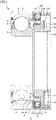
- Fig. 1 is a cross-sectional view of a bearing device according to a first embodiment in a plane including a rotation axis.
- a bearing with a wireless sensor is exemplified as a bearing device 1 illustrated in Fig. 1 .
- Bearing device 1 includes a bearing B, an external ring 7, a magnetic ring 8, and a stator 9.
- Bearing B includes an outer ring 2, an inner ring 3, rolling elements 4, a retainer 5, and a seal 6.
- External ring 7 is fixed to an inner diameter surface of outer ring 2.
- Magnetic ring 8 is fixed to an outer diameter surface of inner ring 3.
- Stator 9 is fixed to the inner diameter surface of external ring 7 so as to face magnetic ring 8.
- Magnetic ring 8 and stator 9 constitute a generator G.
- Generator G is a claw pole generator.
- Bearing B is, for example, a deep groove ball bearing in which rolling elements 4 are balls.
- inner ring rotation type in which inner ring 3 is a rotating wheel and outer ring 2 is a fixed wheel will be described as an example.
- Magnetic ring 8 includes a cored bar 8a and a multipolar magnet 8b.
- Multipolar magnet 8b is obtained by, for example, vulcanizing and bonding a magnetic material obtained by kneading magnetic powder and rubber to cored bar 8a, and then alternately magnetizing N poles and S poles, and is fixed to inner ring (rotating wheel) 3.
- Stator 9 includes two magnetic ring members 10-1 and 10-2 having the same shape, a bobbin 11, and a coil 12.
- the winding of coil 12 is wound a plurality of times in the circumferential direction of bobbin 11.
- a stator can be similarly configured even if a coil not using bobbin 11 is used.
- a resin case 13 is fixed to the inner diameter surface of external ring 7 so as to be adjacent to generator G.
- Circuit board 14 is fixed to case 13.
- Circuit board 14 is provided with a power circuit 15 that rectifies AC power generated by generator G and converts the AC power into DC power, a sensor 16 that monitors a state of bearing B, and a wireless communication circuit 17 that wirelessly transmits an output of sensor 16 to the outside.
- An end portion 12a that is a start of winding of coil 12 and an end portion 12b that is an end of winding of the coil are connected to circuit board 14.
- a lid 18 that protects circuit board 14 is made of a nonmagnetic insulator such as resin, and is fixed to external ring 7, for example.
- a surface of circuit board 14 may be sealed with a resin molding agent instead of lid 18.
- Circuit board 14 on which wireless communication circuit 17 is mounted is surrounded by a nonmagnetic insulator such as resin. Since a magnetic material or a conductor is not disposed on a side of lid 18 of circuit board 14, wireless communication is possible.
- case 13 is interposed between bearing B and circuit board 14.
- case 13 is made of a resin material having a low thermal conductivity, it is also possible to suppress rise of the temperature of circuit board 14.
- a material having excellent heat insulating properties such as resin containing fine bubbles, it is effective to suppress the temperature rise.
- seal 6 is not mounted on a side of bearing B to which magnetic ring 8 is fixed, making a gap between magnetic ring 8 and components such as stator 9 and case 13 narrowed provides a labyrinth seal (non-contact seal) structure, and thus it is possible to prevent foreign matters and the like from entering.
- a groove or the like may be provided on any of the opposing surfaces, or a contact type seal may be provided.
- FIG. 2 is a diagram illustrating a schematic configuration of generator G.
- Generator G is a claw pole type generator.
- a magnetic rotor includes a ring-shaped multipolar magnet 8b.
- stator 9 includes coil 12 and a magnetic yoke surrounding the coil.
- the magnetic yoke includes magnetic ring members 10-1 and 10-2.
- a magnetic flux emitted from the N pole of multipolar magnet 8b enters the magnetic yoke from a claw 10b which is a magnetic pole, goes around the coil, and enters the S pole of multipolar magnet 8b from claw 10b which is an adjacent magnetic pole.
- directions of the magnetic fluxes are reversed.
- the alternating magnetic fields generated in this manner generate an AC voltage at both ends of coil 12.
- Fig. 3 is a side view of a magnetic ring member 10.
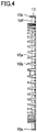
- Fig. 4 is a cross-sectional view taken along line IV-IV of Fig. 3 . Referring to Figs. 3 and 4 , at one end of magnetic ring member 10, grooves 10a and claws 10b opened in an axial direction are alternately arranged in a comb shape.
- a recess 10c and a protrusion 10d are provided on an end surface 10f of magnetic ring member 10.
- positions of recess 10c and protrusion 10d are designed such that protrusion 10d of one magnetic ring member 10-2 is arranged with respect to recess 10c of the other magnetic ring member 10-1.
- a plurality of recesses and protrusions may be provided as illustrated in Fig. 3 .
- assembly is possible as long as protrusion 10d illustrated in a circle V1 and recess 10c illustrated in a circle V2 in Fig. 3 are provided.
- two recesses 10c and two protrusions 10d are provided in Fig. 3 in consideration of the balance at the time of assembly.
- a hole 10e provided in the side surface is provided in magnetic ring member 10 in order to pull out end portions 12a and 12b of coil 12 to the outside.
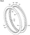
- Fig. 5 is a view illustrating a state in which two magnetic ring members 10 having the same shape are arranged to face each other.
- bobbin 11 wound with coil 12 is accommodated in a space between two magnetic ring members 10-1 and 10-2, but bobbin 11 wound with coil 12 is not illustrated here because the drawing becomes complicated.
- the number of magnetic poles of magnetic ring 8 including the N pole and the S pole is the same as that of claw 10b in the state of Fig. 6 .
- Fig. 6 is a view illustrating a state in which two magnetic ring members 10 are fitted.
- Fig. 7 is a cross-sectional view of a portion VII in Fig. 6 after fitting of the two magnetic ring members on a plane including the rotation axis of the bearing.
- bobbin 11 and coil 12 are arranged inside the stator as in Fig. 1 and the like, bobbin 11 and coil 12 are not illustrated in Fig. 7 .
- Two magnetic ring members 10-1, 10-2 of the same shape are used. Recess 10c and protrusion 10d provided on end surface 10f of each magnetic ring member 10 are fitted so that claws 10b provided on each magnetic ring member 10 are alternately arranged.
- end surface 10f of magnetic ring member 10 On end surface 10f of magnetic ring member 10, the same number of recesses 10c and protrusions 10d are provided.
- recesses 10c and protrusions 10d When recesses 10c and protrusions 10d are fitted and end surfaces 10f are brought into contact with each other, it is easy to align the phases of the arrangements so that a gap between claw 10b and claw 10b of respective magnetic ring members 10 become uniform.
- the plurality of recesses 10c and the plurality of protrusions 10d are arranged in the circumferential direction, the positions of magnetic ring members 10 can be fixed without being displaced from each other in the circumferential direction.
- End surfaces 10f of two magnetic ring members 10 come into contact with each other without a gap and provide a magnetic path.
- external ring 7 can be used as a magnetic path, and the magnetic resistance of the magnetic yoke can be suppressed to be small.
- two magnetic ring members 10 can be easily assembled without adhesion or welding.
- plastic working such as caulking (not illustrated) may be added to the fitting portion, or the fitting portion may be elastically deformed.
- magnetic ring member 10 is generally manufactured by press-forming a thin plate of a magnetic material with a die, but other than this method, the magnetic material may be deposited on the surface by plating, electrodeposition, or the like after injection molding of a resin material. In this manufacturing method, it is easy to manufacture even a fine claw shape that is difficult to plastically process by pressing.
- Fig. 8 is a diagram illustrating a configuration of circuit board 14.
- Circuit board 14 is provided with power circuit 15, sensor 16, and wireless communication circuit 17.
- Power circuit 15 smooths an alternating current obtained from generator G into a direct current, and boosts or steps down the alternating current at a subsequent stage to generate a DC power supply GV for driving sensor 16 and wireless communication circuit 17. Since a frequency of an AC signal obtained from generator G changes according to the rotation speed of inner ring 3, a rotation detection unit 20 can process the AC signal to obtain a rotation signal RP.
- Rotation detection unit 20 may be such a transistor.
- Sensor 16 is, for example, a temperature sensor or an acceleration sensor that monitors the state of bearing B.
- sensor 16 is mounted on circuit board 14, but the temperature sensor may be fixed in contact with or in the vicinity of outer ring 2 so as to directly measure the temperature of bearing B, and a sensor signal may be input to circuit board 14.
- Wireless communication circuit 17 includes an input unit 17a that inputs a sensor signal, an arithmetic unit 17b that performs arithmetic processing on the sensor signal, a transmission/reception unit 17c for transmitting and receiving data, and an antenna 17d.
- input unit 17a may include a DA converter. With such a configuration, by converting the sensor output into a digital signal in the immediate vicinity of sensor 16, it is possible to suppress mixing of electromagnetic noise.
- arithmetic unit 17b has functions of a central processing unit (CPU) and a memory, and performs arithmetic processing on information obtained from sensor 16.
- Wireless communication circuit 17 is, for example, a module compatible with a wireless standard such as Bluetooth (registered trademark) or Bluetooth Low Energy (registered trademark).
- wireless communication circuit 17 is preferably a circuit that can be driven with low power.
- wireless communication circuit 17 may be a communication circuit other than the wireless standards described above.
- circuit board 14 is fixed via case 13 made of a nonmagnetic material, a distance between antenna 17d and a magnetic material such as stator 9 can be increased, and therefore an influence on wireless communication is reduced.
- stator 9 from being arranged on a back side of wireless communication circuit 17, the influence on the wireless communication can be further reduced.
- the signal of sensor 16 may be processed into an index according to a purpose, such as a result of calculation of an average value by arithmetic unit 17b or a maximum value and a minimum value within a certain period of time, and then transmitted.
- a purpose such as a result of calculation of an average value by arithmetic unit 17b or a maximum value and a minimum value within a certain period of time.
- Fig. 9 is a diagram illustrating an improved example of circuit board 14 of Fig. 8 .
- generator G using the rotation of inner ring 3 When generator G using the rotation of inner ring 3 is used, necessary electric power cannot be secured unless inner ring 3 rotates at a certain speed or more. Therefore, in Fig. 9 , a battery 21 is mounted in addition to generator G. As such a configuration, when the power required by generator G cannot be secured, the power may be switched to the battery drive by a switch unit 19 and used. In addition, power generated by generator G may be stored in battery 21, and data may be intermittently transmitted after a sufficient amount of power is stored.
- Fig. 10 is a cross-sectional view of a bearing device 1A according to a first modification of the first embodiment in a plane including a rotation axis.
- Bearing device 1A is a bearing with a wireless sensor as an improved example of Fig. 1 .
- case 13 is disposed so as to be inserted into an inner diameter portion of magnetic ring 8, and circuit board 14 is disposed inside the case. Therefore, a width in the axial direction can be reduced as compared with the example of Fig. 1 , and magnetic ring 8 can be made compact.
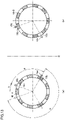
- Fig. 11 is a view for illustrating a condition for correspondingly fitting recess 10c and protrusion 10d provided for two magnetic ring members 10.
- recess 10c is indicated by a white circle
- protrusion 10d is indicated by a hatched circle.
- Fig. 11(a) is a view of magnetic ring member 10-1 viewed from the side of recess 10c and protrusion 10d, and shows an example in which one recess 10c and one protrusion 10d are provided.
- Recess 10c is provided at a position of ⁇ from the reference position
- protrusion 10d is provided at a position of ⁇ from recess 10c.
- Fig. 11(b) is a view illustrating arrangement of magnetic ring member 10-2.
- the arrangement of magnetic ring member 10-2 corresponds to the arrangement obtained by rotating Fig. 11(a) clockwise by an angle ⁇ so as to be line-symmetric with respect to a line O.
- recess 10c provided in magnetic ring member 10-1 and protrusion 10d provided in magnetic ring member 10-2 are fitted, and recess 10c provided in magnetic ring member 10-2 and protrusion 10d provided in magnetic ring member 10-1 are fitted.
- Fig. 12 is a view illustrating a phase of two magnetic ring members 10 in which groove 10a and claw 10b fit alternately.
- Fig. 12(a) illustrates arrangement of the groove and the claw of magnetic ring member 10-1.
- Fig. 12(b) illustrates arrangement of the groove and the claw of magnetic ring member 10-1.
- the state illustrated in Fig. 12(b) corresponds to a state of being rotated at angle ⁇ from the state of Fig. 12(a) .
- i represents an integer indicating the number of pitches to be shifted at the time of fitting
- n represents the number of grooves 10a and claws 10b of magnetic ring member 10
- 2 ⁇ /n represents a pitch P of the claws.
- outer ring 2 of bearing B is fixed to the stationary member
- inner ring 3 is fixed to the rotary member
- the rotary member is supported with respect to the stationary member.
- the present invention can be similarly applied to a case where the outer ring is rotational and the inner ring is stationary.
- Fig. 14 is a cross-sectional view of a bearing device 1B according to a second modification of the first embodiment in a plane including the rotation axis of bearing device 1B.
- Bearing device 1B is a modification of bearing device 1A illustrated in Fig. 10 , and is a bearing with a wireless sensor in which the outer ring is rotational.
- magnetic ring 8 is fixed to an inner diameter portion of outer ring 2, and multipolar magnet 8b is provided on a side of an inner diameter of cored bar 8a.
- a ring member 30 is fixed to an outer diameter surface of inner ring 3 serving as a fixed wheel.
- Stator 9 is fixed to a side of an outer diameter of ring member 30, and case 13 is fixed to a side of an inner diameter of the ring member.
- the claws aligned in a comb shape are arranged on the outer periphery of stator 9.
- Case 13 has a flange portion 30a protruding toward on the side of the outer diameter.
- a labyrinth structure in which a gap between flange portion 30a and magnetic ring 8 is narrowed is provided. The labyrinth structure prevents a foreign matter from entering.
- Circuit board 14 is fixed in the groove provided in case 13.
- Circuit board 14 is provided with power circuit 15 that rectifies AC power generated by generator G and converts the AC power into DC power, sensor 16 that monitors a state of bearing B, and wireless communication circuit 17 that wirelessly transmits an output of sensor 16 to the outside.
- End portion 12a that is the start of winding and end portion 12b that is the end of winding drawn from coil 12 are connected to circuit board 14.
- the AC power output from generator G when outer ring 2 rotates is converted into DC by power circuit 15.
- Lid 18 that protects circuit board 14 is made of a nonmagnetic insulator such as resin, and closes the opening of case 13.
- the surface of circuit board 14 may be sealed with a resin molding agent instead of lid 18.
- the first embodiment has described an example in which two magnetic ring members having an identical shape are combined to provide a magnetic ring.
- a second embodiment another example is shown in which two magnetic ring members having an identical shape are similarly combined to provide a magnetic ring. Portions other than the magnetic ring are similar to the configuration described in the first embodiment, and thus only the magnetic ring will be described below.
- Fig. 15 is a side view of a magnetic ring member 10A used in the second embodiment.
- Fig. 16 is a view of magnetic ring member 10A shown in Fig. 15 seen along an XVI arrow.
- grooves 10a and claws 10b opened in the axial direction are alternately arranged in a comb shape at one end of magnetic ring member 10A.
- a plurality of large-diameter portions 10g and small-diameter portions 10h having different outer diameters are provided at the other end.
- the number of large-diameter portions 10g is equal to the number of small-diameter portions 10h.
- a cutout portion 10j is provided at a boundary between large-diameter portion 10g and small-diameter portion 10h.
- Fig. 15 illustrates an example in which two large-diameter portions 10g and two small-diameter portions 10h are disposed.
- Fig. 17 illustrates a state in which two magnetic ring members 10A having the same shape are arranged to face each other.
- Fig. 18 illustrates a state in which two magnetic ring members 10A are fitted.
- large-diameter portion 10g of magnetic ring member 10A-1 is fitted to small-diameter portion 10h of magnetic ring member 10A-2.
- Small-diameter portion 10h of magnetic ring member 10A-1 is fitted to large-diameter portion 10g of magnetic ring member 10A-2.
- Hole 10e provided in the side surface of magnetic ring member 10 is provided to pull out end portions 12a and 12b of coil 12 to the outside.
- bobbin 11 wound with coil 12 is accommodated in a space sandwiched between two magnetic ring members 10A-1 and 10A-2. However, since the drawing becomes complicated, bobbin 11 wound with coil 12 is not illustrated here.
- the number of magnetic poles of magnetic ring 8 including the N pole and the S pole is the same as that of claw 10b in the state of Fig. 18 .
- Fig. 19 is a cross-sectional view of the XIX portion of the stator of Fig. 18 on a plane including the rotation axis.
- Fig. 20 is a cross-sectional view of the XX portion of the stator in Fig. 18 on another plane including the rotation axis.
- bobbin 11 and coil 12 are arranged inside the stator as in Fig. 1 and the like, bobbin 11 and coil 12 are not illustrated in Figs. 19 and 20 .
- Claw 10b of magnetic ring member 10A-1 and claw 10b of magnetic ring member 10A-2 are disposed on one side (upper side in Figs. 19 and 20 ) with respect to coil 12, and in a cross section ( Fig. 20 ) in a certain plane, first member 10A-1 and second member 10A-2 overlap in the order of small-diameter portion 10h of first member 10A-1 and large-diameter portion 10g of second member 10A-2 in a direction away from the coil on a side (lower side in Fig. 20 ) opposite to the one side with respect to the coil.
- a cross section Fig.
- first member 10A-1 and second member 10A-2 overlap in the order of small-diameter portion 10h of second member 10A-2 and large-diameter portion 10g of first member 10A-1 in a direction away from the coil on the side (lower side in Fig. 19 ) opposite to the one side with respect to the coil.
- large-diameter portion 10g of magnetic ring member 10A-1 and small-diameter portion 10h of magnetic ring member 10A-2 are fitted to each other, and large-diameter portion 10g of magnetic ring member 10A-2 and small-diameter portion 10h of magnetic ring member 10A-1 are fitted to each other, such that claws 10b provided on magnetic ring member 10A-1 and claws 10b provided on magnetic ring member 10A-2 are alternately arranged.
- large-diameter portion 10g and small-diameter portion 10h abut on each other on the cylindrical surface, magnetic ring member 10A-1 and magnetic ring member 10A-2 can be restrained in position without being displaced in the circumferential direction, and the magnetic resistance can be reduced.
- large-diameter portion 10g and small-diameter portion 10h are provided, large-diameter portion 10g and small-diameter portion 10h are fitted by aligning the positions of cutout portions 10j, and gaps between claws 10b of magnetic ring member 10A-1 and claws 10b of magnetic ring member 10A-2 becomes uniform. Therefore, it is easy to perform phase matching between magnetic ring member 10A-1 and magnetic ring member 10A-2 at the time of assembly of stator 9.
- a stator structure of the claw pole power generation can be applied not only to the bearing but also to an outer-ring spacer.
- an example in which the stator structure of the claw pole generator is applied to an outer-ring spacer of a spindle device will be described.
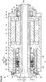
- Fig. 21 is a cross-sectional view illustrating a schematic configuration in which the stator structure of the claw pole generator is applied to a bearing device of the spindle device.
- Fig. 22 is an enlarged view of a main part on the left side in Fig. 21 .
- Fig. 22 mainly illustrates a bearing device 90.
- a spindle device 50 illustrated in Fig. 21 is used as, for example, a built-in motor type spindle device of a machine tool.
- a motor 52 is incorporated on one end side of a spindle 51 supported by spindle device 50 for a machine tool spindle, and a cutting tool such as an end mill (not illustrated) is connected to the other end side.
- spindle device 50 includes bearings 53a and 53b, a spacer 54 disposed adjacent to bearings 53a and 53b, motor 52, and a bearing 55 disposed adjacent to motor 52 on a side opposite to spacer 54.
- Spindle 51 is rotatably supported by a plurality of bearings 53a and 53b provided in a housing 57 embedded in the inner diameter portion of an outer cylinder 56.
- Bearing 53a includes an inner ring 53ia, an outer ring 53ga, rolling elements Ta, and a retainer Rta.
- Bearing 53b includes an inner ring 53ib, an outer ring 53gb, rolling elements Tb, and a retainer Rtb.
- Spacer 54 includes an inner-ring spacer 54i and an outer-ring spacer 54g.
- rolling elements Ta and Tb are ceramic balls that are nonmetallic insulators, and retainers Rta and Rtb are made of resin.
- Inner ring 53ia of bearing 53a and inner ring 53ib of a bearing 5b separated in the axial direction are fitted to spindle 51 in an interference fit state (press fit state).
- Inner-ring spacer 54i is disposed between inner rings 53ia-53ib, and outer-ring spacer 54g is disposed between outer rings 53ga-53gb.
- Bearings 53a and 53b are bearings capable of applying a preload by an axial force, and an angular ball bearing, a deep groove ball bearing, a tapered roller bearing, or the like can be used.
- An angular ball bearing is used as bearing device 90 illustrated in Fig. 22 , and two bearings 53a and 53b are installed in back-to-back duplex (DB).
- Outer-ring spacer 54g is divided into two parts of a first outer-ring spacer 54g1 and a second outer-ring spacer 54g2 in the axial direction, and stator 9 of generator G is fixed therebetween.
- magnetic ring 8 is fixed to an outer peripheral surface of inner-ring spacer 54i, and stator 9 and multipolar magnet 8b of magnetic ring 8 are arranged to face each other with a gap therebetween, and thus generator G is configured.
- generator G the claw pole generator illustrated in Figs. 2 to 7 and 15 to 20 can be used.
- Magnetic ring 8 includes cored bar 8a and multipolar magnet 8b.
- Multipolar magnet 8b is obtained by, for example, vulcanizing and bonding a magnetic material obtained by kneading magnetic powder and rubber to cored bar 8a, and then alternately magnetizing N poles and S poles, and is fixed to inner-ring spacer 54i.
- Stator 9 includes two magnetic ring members 10-1 and 10-2 having the same shape, bobbin 11, and coil 12.
- the winding of coil 12 is wound a plurality of times in the circumferential direction of bobbin 11.
- bobbin 11 an example of using bobbin 11 is illustrated here, a stator can be similarly configured even if a coil not using bobbin 11 is used.
- a groove portion 54gla is provided on an end surface of first outer-ring spacer 54g1, and circuit board 14 is mounted inside groove portion 54gla.
- Circuit board 14 is provided with power circuit 15 that rectifies AC power generated by generator G and converts the AC power into DC power, sensor 16 that monitors the state of bearing device 90, and wireless communication circuit 17 that wirelessly transmits an output of sensor 16 to the outside.
- End portion 12a that is the start of winding of coil 12 and end portion 12b that is the end of winding of the coil are connected to circuit board 14 through a hole 54glb.
- hole 54g1b is sealed using a sealing material after wiring to prevent oil or the like from entering a side of circuit board 14.
- Lid 18 that protects circuit board 14 is made of a nonmetallic insulator such as resin, and is fixed inside groove portion 54gla.
- the surface of circuit board 14 may be sealed with a resin molding agent instead of lid 18.
- a plurality of sensors such as a temperature sensor, an acceleration sensor, and a load sensor are mounted.
- the load sensor (not illustrated) is disposed between first outer-ring spacer 54g1 and second outer-ring spacer 54g2, signal processing is performed by circuit board 14, and an output thereof is wirelessly transmitted.
- Rolling bearing 55 of a single row is a cylindrical roller bearing.
- a radial load and an axial load acting on spindle device 50 are supported by bearings 53a and 53b as angular ball bearings.
- the load in the radial direction acting on spindle device 50 for a machine tool spindle is supported by single-row bearing 55 as a cylindrical roller bearing.
- a cooling medium flow path GV is provided in housing 57. By allowing a cooling medium to flow between housing 57 and outer cylinder 56, bearings 53a and 53b can be cooled.
- a lubricating oil supply passage is unnecessary, but when lubrication of air oil or the like is necessary, a lubricating oil supply passage is provided for outer-ring spacer 54g. Here, the lubricating oil supply passage is not illustrated.
- bearing 53a, spacer 54, bearing 53b, and a spacer 58 are inserted into spindle 51 in the stated order, and an initial preload is applied by tightening a nut 59.
- spindle 51 to which bearings 53a and 53b are attached is inserted into housing 57 until the right side of outer ring 53gb of bearing 53b in Fig. 22 is brought into contact with a stepped portion 57a provided in housing 57.
- a front lid 60 pushes outer ring 53ga of left bearing 53a to fix spindle 51 to housing 57.
- This force is transmitted to outer ring 53ga, rolling elements Ta, and inner ring 53ia in bearing 53a to apply a preload between raceway surfaces of inner ring 53ia and outer ring 53ga of a left bearing 5a and rolling elements Ta.
- the preload applied to bearings 53a and 53b is determined by, for example, a movement amount limited by a dimensional difference between a width of outer-ring spacer 54g and a width of inner-ring spacer 54i.
- an inner ring 55a is positioned in the axial direction by a cylindrical member 61 and an inner ring retainer 62 fitted to the outer periphery of spindle 51.
- Inner ring retainer 62 is prevented from coming off by a nut 63 screwed to spindle 51.
- An outer ring 55b of bearing 55 is sandwiched between a positioning member 65 and a positioning member 66 fixed to an end member 64.
- Inner ring 55a slides integrally with respect to end member 64 in accordance with expansion and contraction of spindle 51.
- Motor 52 that drives spindle 51 is disposed at an intermediate position in the axial direction between bearing 53b and single-row bearing 55 in a space 67 provided between spindle 51 and outer cylinder 56.
- a rotor 68 of motor 52 is fixed to cylindrical member 61 fitted to the outer periphery of spindle 51, and a stator 69 of motor 52 is fixed to the inner peripheral portion of outer cylinder 56.
- cooling medium flow path for cooling motor 52 is not illustrated.
- Outer-ring spacer 54g is provided with generator G, sensor 16, and wireless communication circuit 17 that wirelessly transmits the output of sensor 16 to the outside, and the operation status of spindle device 50 can be monitored and the sensor output can be wirelessly transmitted.
- an abnormality determination means (not illustrated) that determines the presence or absence of an abnormality from each sensor output may be mounted on circuit board 14, and an abnormality determination result may be wirelessly transmitted.
- the radio wave transmitted from wireless communication circuit 17 passes between outer ring 53ga and inner ring 53ia of bearing 53a, and is emitted from a gap 70 of the labyrinth seal provided by spindle 51 and front lid 60.
- spindle device 50 performs wireless communication, the wiring does not need to be drawn out from outer-ring spacer 54g. Therefore, it is not necessary to process a groove for wiring on the inner diameter side of housing 57, and the modification of spindle device 50 can be minimized.
- outer-ring spacer 54g and inner-ring spacer 54i are further provided.
- Magnetic ring 8 is fixed to inner-ring spacer 54i
- stator 9 is fixed to outer-ring spacer 54g so as to face magnetic ring 8.
- magnetic ring 8 may be fixed to outer-ring spacer 54g
- stator 9 may be fixed to inner-ring spacer 54i so as to face magnetic ring 8.
- circuit board 14 is fixed to inner-ring spacer 54i.
- bearing device 1 includes magnetic ring 8 fixed to a rotary member, and a stator 9 fixed to a non-rotary member so as to face magnetic ring 8.
- Magnetic ring 8 and stator 9 constitute claw pole type generator G.
- Stator 9 includes coil 12 and a magnetic yoke surrounding coil 12.
- the magnetic yoke is configured by combining first member 10-1 and second member 10-2 that are magnetic bodies.
- First member 10-1 includes a plurality of first claws 10b arranged in a comb shape
- second member 10-2 includes a plurality of second claws 10b arranged in a comb shape.
- the plurality of first claws 10b of first member 10-1 and the plurality of second claws 10b of second member 10-2 are alternately arranged on the surface facing magnetic ring 8.
- First member 10-1 and second member 10-2 have an identical shape.
- bearing device 1 further includes outer ring 2, inner ring 3 and a plurality of rolling elements 4 arranged between outer ring 2 and inner ring 3.
- Magnetic ring 8 is fixed to one of outer ring 2 and inner ring 3.
- Stator 9 is fixed to the other of outer ring 2 and inner ring 3 so as to face magnetic ring 8.
- bearing device 90 shown in Figs. 21 and 22 further includes outer-ring spacer 54g and inner-ring spacer 54i.
- Magnetic ring 8 is fixed to inner-ring spacer 54i
- stator 9 is fixed to outer-ring spacer 54g so as to face magnetic ring 8.
- magnetic ring 8 may be fixed to outer-ring spacer 54g
- stator 9 may be fixed to inner-ring spacer 54i so as to face magnetic ring 8.
- Stator 9 and magnetic ring 8 have an annular shape through which the rotation axis of bearing device 1 passes.
- first claws 10b and second claws 10b are arranged on one side with respect to coil 12, and end surface 10f of first member 10-1 and end surface 10f of second member 10-2 abut on the side opposite to the one side with respect to coil 12 in the cross section.
- a first recess 10c and a first protrusion 10d are provided on end surface 10f of first member 10-1, and a second recess 10c and a second protrusion 10d are provided on the end surface of the second member.
- first recess 10c abuts on second protrusion 10d
- first protrusion 10d abuts on second recess 10c.
- coil 12 illustrated in Fig. 2 and surrounded by first member 10-1 and second member 10-2 is not illustrated in Fig. 7 .
- ⁇ represents a rotation angle between first member 10-1 and second member 10-2
- ⁇ represents an angle indicating a position of first recess 10c from a reference position
- ⁇ represents an angle indicating a position of first protrusion 10d from the position of first recess 10c.
- ⁇ represents a rotation angle between first member 10-1 and second member 10-2.
- i represents an integer.
- n represents the number of the plurality of first claws 10b of first member 10-1 and the number of the plurality of second claws 10b of second member 10-2.
- 2 ⁇ /n represents each pitch P of the plurality of first claws 10b of first member 10-1 and the plurality of second claws 10b of second member 10-2.
- Stator 9 and magnetic ring 8 have an annular shape through which the rotation axis of bearing device 1 passes.
- one of first claw 10b of first member 10A-1 and second claw 10b of second member 10A-2 is disposed on one side (upper side in Figs. 19 and 20 ) with respect to coil 12.
- first member 10A-1 and second member 10A-2 overlap in the order of first member 10A-1 and second member 10A-2 in the direction away from the coil on a side opposite to the one side (lower side in Fig. 20 ) with respect to the coil.
- first member 10A-1 and second member 10A-2 overlap in the order of second member 10A-2 and first member 10A-1 in the direction away from the coil on a side opposite to the one side with respect to the coil.
- first member 10A-1 and second member 10A-2 overlap each other at the portion opposite to claw 10b, the contact area can be increased to reduce the magnetic resistance of the magnetic yoke.
- the manufacturing method for manufacturing the bearing device or the spacer includes: punching first member 10-1 and second member 10-2 by press working, using a die having an identical shape; and assembling first member 10-1, second member 10-2, and coil 12 to constitute stator 9.
- 1, 1A, 1B, 90 bearing device, 2, 53ga, 53gb, 55b: outer ring, 3, 53ia, 53ib, 55a: inner ring, 4, Ta, Tb: rolling element, 5, Rta, Rtb: retainer, 5a, 5b, 53a, 53b, 55, B: bearing, 6: seal, 7: external ring, 8: magnetic ring, 8a: cored bar, 8b: multipolar magnet, 9, 69: stator, 10, 10-1, 10-2, 10A, 10A-1, 10A-2: magnetic ring member, 10a: groove, 10b: claw, 10c: recess, 10d: protrusion, 10e: hole, 10f: end surface, 10g: large-diameter portion, 10h: small-diameter portion, 10j: cutout portion, 11: bobbin, 12: coil, 12a, 12b: end portion, 13: case, 14: circuit board, 15: power circuit, 16: sensor, 17: wireless communication circuit, 17a: input unit,
Landscapes
- Engineering & Computer Science (AREA)
- General Engineering & Computer Science (AREA)
- Mechanical Engineering (AREA)
- Power Engineering (AREA)
- Physics & Mathematics (AREA)
- General Physics & Mathematics (AREA)
- Microelectronics & Electronic Packaging (AREA)
- Rolling Contact Bearings (AREA)
Abstract
Description
- The present invention relates to a bearing device, a spacer, and a manufacturing method.
- It is known that a generator combined with a bearing is used as a power source for a sensor, wireless communication, or the like. A bearing with a wireless sensor disclosed in
Japanese Patent Laying-Open No. 2006-170624 - PTL 1:
Japanese Patent Laying-Open No. 2006-170624 - The rotation sensor serving also as a generator, of the bearing with a wireless sensor disclosed in
Japanese Patent Laying-Open No. 2006 -170624 - The magnetic ring is a ring body having a substantially rectangular cross section in a plane including a rotation axis of the bearing. The magnetic ring is configured by combining two magnetic ring members having a groove-shaped cross-sectional shape opened in a direction of the rotation axis. The two magnetic ring members are arranged such that the two magnetic ring members face each other with their openings facing each other, and the two magnetic ring members are in contact with each other with no gap therebetween in the outer diameter portion. In this manner, by preventing the contact portions of both the magnetic ring members from forming a gap, magnetic resistance at a fitting portion in a magnetic circuit inside the magnetic ring is suppressed to be small.
- In the magnetic ring described in
PTL 1, it is necessary to prepare two magnetic ring members having different shapes. When the magnetic ring member is press-formed with a die, different dies are required, and therefore initial manufacturing cost increases. - The present invention has been made to solve the above problems, and an object of the present invention is to provide a bearing device, a spacer, and a manufacturing method of these capable of simplifying a configuration of the generator and reducing initial manufacturing cost.
- The present disclosure relates to a bearing device or a spacer that rotatably supports a rotary member. The bearing device or the spacer includes: a magnetic ring fixed to the rotary member; and a stator fixed to a non-rotary member so as to face the magnetic ring. The magnetic ring and the stator constitute a claw pole type generator. The stator includes: a coil; and a magnetic yoke surrounding the coil. The magnetic yoke is configured by combining a first member and a second member that are magnetic bodies. The first member includes a plurality of first claws arranged in a comb shape. The second member includes a plurality of second claws arranged in a comb shape. The plurality of first claws and the plurality of second claws are alternately arranged on a surface facing the magnetic ring. The first member and the second member have an identical shape.
- According to the bearing device or the spacer of the present disclosure, only one type of die for press-forming is required since the two magnetic rings are configured as parts having an identical shape, and therefore it is possible to suppress initial manufacturing cost and to suppress manufacturing cost by eliminating die replacement when the magnetic ring is manufactured.
-
-
Fig. 1 is a cross-sectional view of a bearing device according to a first embodiment. -
Fig. 2 is a diagram illustrating a schematic configuration of a generator G. -
Fig. 3 is a side view of amagnetic ring member 10. -
Fig. 4 is a cross-sectional view taken along line IV-IV ofFig. 3 . -
Fig. 5 is a view illustrating a state in which twomagnetic ring members 10 having the same shape are arranged to face each other. -
Fig. 6 is a view illustrating a state in which twomagnetic ring members 10 are fitted. -
Fig. 7 is a cross-sectional view at VII inFig. 6 after fitting of the two magnetic ring members. -
Fig. 8 is a diagram illustrating a configuration of acircuit board 14. -
Fig. 9 is a diagram illustrating an improved example ofcircuit board 14 ofFig. 8 . -
Fig. 10 is a cross-sectional view of abearing device 1A according to a first modification of the first embodiment. -
Fig. 11 is a view for illustrating a condition for fitting arecess 10c and aprotrusion 10d. -
Fig. 12 is a view illustrating a phase in which grooves 10a andclaws 10b fit alternately. -
Fig. 13 is a view of another example in which a number n ofgrooves 10a andclaws 10b is an odd number. -
Fig. 14 is a cross-sectional view of abearing device 1B according to a second modification of the first embodiment. -
Fig. 15 is a side view of amagnetic ring member 10A used in a second embodiment. -
Fig. 16 is a view ofmagnetic ring member 10A shown inFig. 15 seen along an XVI arrow. -
Fig. 17 illustrates a state in which twomagnetic ring members 10A having the same shape are arranged to face each other. -
Fig. 18 illustrates a state in which twomagnetic ring members 10A are fitted. -
Fig. 19 is a cross-sectional view of a stator on a plane including a rotation axis. -
Fig. 20 is a cross-sectional view of the stator on another plane including the rotation axis. -
Fig. 21 is a cross-sectional view illustrating a schematic configuration in which a stator structure of a claw pole generator is applied to a bearing device of a spindle device. -
Fig. 22 is an enlarged view of a main part on the left side inFig. 21 . - Hereinafter, embodiments of the present invention will be described with reference to the drawings. In the following drawings, the same or corresponding parts are denoted by the same reference numerals, and description thereof will not be repeated.
-
Fig. 1 is a cross-sectional view of a bearing device according to a first embodiment in a plane including a rotation axis. A bearing with a wireless sensor is exemplified as abearing device 1 illustrated inFig. 1 .Bearing device 1 includes a bearing B, anexternal ring 7, amagnetic ring 8, and astator 9. Bearing B includes anouter ring 2, aninner ring 3,rolling elements 4, aretainer 5, and aseal 6.External ring 7 is fixed to an inner diameter surface ofouter ring 2.Magnetic ring 8 is fixed to an outer diameter surface ofinner ring 3.Stator 9 is fixed to the inner diameter surface ofexternal ring 7 so as to facemagnetic ring 8. -
Magnetic ring 8 andstator 9 constitute a generator G. Generator G is a claw pole generator. Bearing B is, for example, a deep groove ball bearing in which rollingelements 4 are balls. Here, an inner ring rotation type in whichinner ring 3 is a rotating wheel andouter ring 2 is a fixed wheel will be described as an example. -
Magnetic ring 8 includes a coredbar 8a and amultipolar magnet 8b.Multipolar magnet 8b is obtained by, for example, vulcanizing and bonding a magnetic material obtained by kneading magnetic powder and rubber to coredbar 8a, and then alternately magnetizing N poles and S poles, and is fixed to inner ring (rotating wheel) 3. -
Stator 9 includes two magnetic ring members 10-1 and 10-2 having the same shape, abobbin 11, and acoil 12. The winding ofcoil 12 is wound a plurality of times in the circumferential direction ofbobbin 11. Although an example of usingbobbin 11 is illustrated here, a stator can be similarly configured even if a coil not usingbobbin 11 is used. - A
resin case 13 is fixed to the inner diameter surface ofexternal ring 7 so as to be adjacent to generatorG. Circuit board 14 is fixed tocase 13.Circuit board 14 is provided with apower circuit 15 that rectifies AC power generated by generator G and converts the AC power into DC power, asensor 16 that monitors a state of bearing B, and awireless communication circuit 17 that wirelessly transmits an output ofsensor 16 to the outside. Anend portion 12a that is a start of winding ofcoil 12 and anend portion 12b that is an end of winding of the coil are connected tocircuit board 14. Wheninner ring 3 rotates, AC power output from generator G is converted into DC bypower circuit 15. Alid 18 that protectscircuit board 14 is made of a nonmagnetic insulator such as resin, and is fixed toexternal ring 7, for example. A surface ofcircuit board 14 may be sealed with a resin molding agent instead oflid 18. -
Circuit board 14 on whichwireless communication circuit 17 is mounted is surrounded by a nonmagnetic insulator such as resin. Since a magnetic material or a conductor is not disposed on a side oflid 18 ofcircuit board 14, wireless communication is possible. - Further,
case 13 is interposed between bearing B andcircuit board 14. Although the temperature of bearing B may rise due to friction during rotation, ifcase 13 is made of a resin material having a low thermal conductivity, it is also possible to suppress rise of the temperature ofcircuit board 14. For example, when a material having excellent heat insulating properties, such as resin containing fine bubbles, is used, it is effective to suppress the temperature rise. - Although
seal 6 is not mounted on a side of bearing B to whichmagnetic ring 8 is fixed, making a gap betweenmagnetic ring 8 and components such asstator 9 andcase 13 narrowed provides a labyrinth seal (non-contact seal) structure, and thus it is possible to prevent foreign matters and the like from entering. In order to improve sealing characteristics as necessary, a groove or the like may be provided on any of the opposing surfaces, or a contact type seal may be provided. -
Fig. 2 is a diagram illustrating a schematic configuration of generator G. Generator G is a claw pole type generator. A magnetic rotor includes a ring-shapedmultipolar magnet 8b. Further,stator 9 includescoil 12 and a magnetic yoke surrounding the coil. The magnetic yoke includes magnetic ring members 10-1 and 10-2. A magnetic flux emitted from the N pole ofmultipolar magnet 8b enters the magnetic yoke from aclaw 10b which is a magnetic pole, goes around the coil, and enters the S pole ofmultipolar magnet 8b fromclaw 10b which is an adjacent magnetic pole. When the positions of the N pole and the S pole ofmultipolar magnet 8b are switched depending on a rotation angle of the magnetic rotor, directions of the magnetic fluxes are reversed. The alternating magnetic fields generated in this manner generate an AC voltage at both ends ofcoil 12. -
Fig. 3 is a side view of amagnetic ring member 10.Fig. 4 is a cross-sectional view taken along line IV-IV ofFig. 3 . Referring toFigs. 3 and4 , at one end ofmagnetic ring member 10,grooves 10a andclaws 10b opened in an axial direction are alternately arranged in a comb shape. - A
recess 10c and aprotrusion 10d are provided on anend surface 10f ofmagnetic ring member 10. When two magnetic ring members 10-1 and 10-2 having an identical shape are opposed to each other andclaws 10b are alternately arranged, positions ofrecess 10c andprotrusion 10d are designed such thatprotrusion 10d of one magnetic ring member 10-2 is arranged with respect torecess 10c of the other magnetic ring member 10-1. - Although at least one
recess 10c and oneprotrusion 10d are sufficient, a plurality of recesses and protrusions may be provided as illustrated inFig. 3 . For example, assembly is possible as long asprotrusion 10d illustrated in a circle V1 andrecess 10c illustrated in a circle V2 inFig. 3 are provided. However, in the present embodiment, tworecesses 10c and twoprotrusions 10d are provided inFig. 3 in consideration of the balance at the time of assembly. - In addition, a
hole 10e provided in the side surface is provided inmagnetic ring member 10 in order to pull outend portions coil 12 to the outside. -
Fig. 5 is a view illustrating a state in which twomagnetic ring members 10 having the same shape are arranged to face each other. - In practice,
bobbin 11 wound withcoil 12 is accommodated in a space between two magnetic ring members 10-1 and 10-2, butbobbin 11 wound withcoil 12 is not illustrated here because the drawing becomes complicated. - The number of magnetic poles of
magnetic ring 8 including the N pole and the S pole is the same as that ofclaw 10b in the state ofFig. 6 . -
Fig. 6 is a view illustrating a state in which twomagnetic ring members 10 are fitted.Fig. 7 is a cross-sectional view of a portion VII inFig. 6 after fitting of the two magnetic ring members on a plane including the rotation axis of the bearing.
Althoughbobbin 11 andcoil 12 are arranged inside the stator as inFig. 1 and the like,bobbin 11 andcoil 12 are not illustrated inFig. 7 . - Two magnetic ring members 10-1, 10-2 of the same shape are used.
Recess 10c andprotrusion 10d provided onend surface 10f of eachmagnetic ring member 10 are fitted so thatclaws 10b provided on eachmagnetic ring member 10 are alternately arranged. - On
end surface 10f ofmagnetic ring member 10, the same number ofrecesses 10c andprotrusions 10d are provided. When recesses 10c andprotrusions 10d are fitted andend surfaces 10f are brought into contact with each other, it is easy to align the phases of the arrangements so that a gap betweenclaw 10b and claw 10b of respectivemagnetic ring members 10 become uniform. In addition, since the plurality ofrecesses 10c and the plurality ofprotrusions 10d are arranged in the circumferential direction, the positions ofmagnetic ring members 10 can be fixed without being displaced from each other in the circumferential direction. - End surfaces 10f of two
magnetic ring members 10 come into contact with each other without a gap and provide a magnetic path. However, even if a gap is generated, as long asexternal ring 7 is made of a magnetic material,external ring 7 can be used as a magnetic path, and the magnetic resistance of the magnetic yoke can be suppressed to be small. - By providing two magnetic ring members 10-1 and 10-2 as components having an identical shape, only one type of die is required for press-forming, and the initial manufacturing cost can be kept low. In addition, since the number of man-hours for replacing the die is reduced at the time of manufacturing the magnetic ring, the manufacturing cost can also be suppressed.
- Furthermore, by providing
recess 10c andprotrusion 10d, phase matching between the two magnetic rings at the time of assembly is facilitated, andclaws 10b can be arranged with uniform gaps, and thus assembly is facilitated. - In addition, since
recess 10c andprotrusion 10d provided in twomagnetic ring members 10 are fitted to each other, twomagnetic ring members 10 can be easily assembled without adhesion or welding. - In order to fit more firmly, plastic working such as caulking (not illustrated) may be added to the fitting portion, or the fitting portion may be elastically deformed. When the magnetic resistance at the fitting portion of two
magnetic ring members 10 is further reduced by the firm fitting as described above, power generation performance is improved. - In a case of
magnetic ring members 10 shown inFigs. 2 to 7 , since outer diameters of two magnetic ring members 10-1 and 10-2 disposed opposite to each other are substantially the same,end surface 10f can be firmly brought into contact with each other, and the magnetic resistance is reduced. In addition, since there is no step in the outer diameter, assembly work of insertingstator 9 intoexternal ring 7 is facilitated. - Note that
magnetic ring member 10 is generally manufactured by press-forming a thin plate of a magnetic material with a die, but other than this method, the magnetic material may be deposited on the surface by plating, electrodeposition, or the like after injection molding of a resin material. In this manufacturing method, it is easy to manufacture even a fine claw shape that is difficult to plastically process by pressing. - Also, in this manufacturing method, since only one type of injection molding mold is required, it is possible to suppress the initial manufacturing cost.
-
Fig. 8 is a diagram illustrating a configuration ofcircuit board 14.Circuit board 14 is provided withpower circuit 15,sensor 16, andwireless communication circuit 17.Power circuit 15 smooths an alternating current obtained from generator G into a direct current, and boosts or steps down the alternating current at a subsequent stage to generate a DC power supply GV for drivingsensor 16 andwireless communication circuit 17. Since a frequency of an AC signal obtained from generator G changes according to the rotation speed ofinner ring 3, arotation detection unit 20 can process the AC signal to obtain a rotation signal RP. - For example, when a signal obtained by half-wave rectifying an AC signal with a diode is input to the base of a transistor, a rotation pulse signal corresponding to the rotation speed is obtained, and the rotation speed can be detected.
Rotation detection unit 20 may be such a transistor. -
Sensor 16 is, for example, a temperature sensor or an acceleration sensor that monitors the state of bearing B. InFig. 1 ,sensor 16 is mounted oncircuit board 14, but the temperature sensor may be fixed in contact with or in the vicinity ofouter ring 2 so as to directly measure the temperature of bearing B, and a sensor signal may be input tocircuit board 14. -
Wireless communication circuit 17 includes aninput unit 17a that inputs a sensor signal, anarithmetic unit 17b that performs arithmetic processing on the sensor signal, a transmission/reception unit 17c for transmitting and receiving data, and anantenna 17d. For example, when the sensor output is an analog voltage,input unit 17a may include a DA converter. With such a configuration, by converting the sensor output into a digital signal in the immediate vicinity ofsensor 16, it is possible to suppress mixing of electromagnetic noise. - In addition,
arithmetic unit 17b has functions of a central processing unit (CPU) and a memory, and performs arithmetic processing on information obtained fromsensor 16. -
Wireless communication circuit 17 is, for example, a module compatible with a wireless standard such as Bluetooth (registered trademark) or Bluetooth Low Energy (registered trademark). In a case where the generated power is small,wireless communication circuit 17 is preferably a circuit that can be driven with low power. Here,wireless communication circuit 17 may be a communication circuit other than the wireless standards described above. - It is also assumed that the presence of a magnetic material in the vicinity of
antenna 17d affects wireless communication. However, in the present embodiment, sincecircuit board 14 is fixed viacase 13 made of a nonmagnetic material, a distance betweenantenna 17d and a magnetic material such asstator 9 can be increased, and therefore an influence on wireless communication is reduced. In addition, by preventingstator 9 from being arranged on a back side ofwireless communication circuit 17, the influence on the wireless communication can be further reduced. - The signal of
sensor 16 may be processed into an index according to a purpose, such as a result of calculation of an average value byarithmetic unit 17b or a maximum value and a minimum value within a certain period of time, and then transmitted. By processing the signal ofsensor 16 byarithmetic unit 17b, the amount of transmission data can be reduced, the number of communications can be reduced, and power consumption can be suppressed. -
Fig. 9 is a diagram illustrating an improved example ofcircuit board 14 ofFig. 8 . When generator G using the rotation ofinner ring 3 is used, necessary electric power cannot be secured unlessinner ring 3 rotates at a certain speed or more. Therefore, inFig. 9 , abattery 21 is mounted in addition to generator G. As such a configuration, when the power required by generator G cannot be secured, the power may be switched to the battery drive by aswitch unit 19 and used. In addition, power generated by generator G may be stored inbattery 21, and data may be intermittently transmitted after a sufficient amount of power is stored. - In this way, even when
inner ring 3 rotates at a low speed or stops, the signal ofsensor 16 can be transmitted, and bearing B can be constantly monitored. -
Fig. 10 is a cross-sectional view of abearing device 1A according to a first modification of the first embodiment in a plane including a rotation axis.Bearing device 1A is a bearing with a wireless sensor as an improved example ofFig. 1 . InFig. 10 ,case 13 is disposed so as to be inserted into an inner diameter portion ofmagnetic ring 8, andcircuit board 14 is disposed inside the case. Therefore, a width in the axial direction can be reduced as compared with the example ofFig. 1 , andmagnetic ring 8 can be made compact. -
Fig. 11 is a view for illustrating a condition for correspondinglyfitting recess 10c andprotrusion 10d provided for twomagnetic ring members 10. - In order to simplify the drawing,
recess 10c is indicated by a white circle, andprotrusion 10d is indicated by a hatched circle. -
Fig. 11(a) is a view of magnetic ring member 10-1 viewed from the side ofrecess 10c andprotrusion 10d, and shows an example in which onerecess 10c and oneprotrusion 10d are provided.Recess 10c is provided at a position of θ from the reference position, andprotrusion 10d is provided at a position of ϕ fromrecess 10c. -
Fig. 11(b) is a view illustrating arrangement of magnetic ring member 10-2. The arrangement of magnetic ring member 10-2 corresponds to the arrangement obtained by rotatingFig. 11(a) clockwise by an angle α so as to be line-symmetric with respect to a line O. When bent along line O,recess 10c provided in magnetic ring member 10-1 andprotrusion 10d provided in magnetic ring member 10-2 are fitted, andrecess 10c provided in magnetic ring member 10-2 andprotrusion 10d provided in magnetic ring member 10-1 are fitted. - In order for
recess 10c andprotrusion 10d to be fitted to each other, it is necessary to satisfy the following Formula (1).
-
Fig. 12 is a view illustrating a phase of twomagnetic ring members 10 in whichgroove 10a andclaw 10b fit alternately.Fig. 12(a) illustrates arrangement of the groove and the claw of magnetic ring member 10-1.Fig. 12(b) illustrates arrangement of the groove and the claw of magnetic ring member 10-1. The state illustrated inFig. 12(b) corresponds to a state of being rotated at angle α from the state ofFig. 12(a) . - In order for
grooves 10a andclaws 10b to be alternately fitted when bent along line O, it is necessary to satisfy relationship shown in the following Formula (2).
- In the above, i represents an integer indicating the number of pitches to be shifted at the time of fitting, n represents the number of
grooves 10a andclaws 10b ofmagnetic ring member 10, and 2π/n represents a pitch P of the claws. In order to shift by 1/2 pitch so that the claws are alternately arranged, 1/2 is added to i in Formula (2). - Since α in Formula (1) is equal to α in Formula (2), the following Formula (3) is obtained by solving these formulas for i.

- That is, as the positions of
recess 10c andprotrusion 10d, ϕ may be selected such that the right side of Formula (3) is an integer with respect to number n ofgrooves 10a andclaws 10b. For example, assuming that θ = π/6, ϕ = π/2, and n = 6, then i = 3. -
Fig. 13 is a diagram illustrating another example in which number n ofgrooves 10a andclaws 10b is an odd number. In the example illustrated inFig. 13 , assuming that θ = π/9, n = 9, and ϕ = 5π/9, then i = 5. - The above embodiment has described the example in which
outer ring 2 of bearing B is fixed to the stationary member,inner ring 3 is fixed to the rotary member, and the rotary member is supported with respect to the stationary member. However, the present invention can be similarly applied to a case where the outer ring is rotational and the inner ring is stationary. -
Fig. 14 is a cross-sectional view of abearing device 1B according to a second modification of the first embodiment in a plane including the rotation axis of bearingdevice 1B.Bearing device 1B is a modification of bearingdevice 1A illustrated inFig. 10 , and is a bearing with a wireless sensor in which the outer ring is rotational. - In
Fig. 14 ,magnetic ring 8 is fixed to an inner diameter portion ofouter ring 2, andmultipolar magnet 8b is provided on a side of an inner diameter of coredbar 8a. Aring member 30 is fixed to an outer diameter surface ofinner ring 3 serving as a fixed wheel.Stator 9 is fixed to a side of an outer diameter ofring member 30, andcase 13 is fixed to a side of an inner diameter of the ring member. InFig. 14 , since the outer periphery ofstator 9 facesmagnetic ring 8, the claws aligned in a comb shape are arranged on the outer periphery ofstator 9. -
Case 13 has aflange portion 30a protruding toward on the side of the outer diameter. A labyrinth structure in which a gap betweenflange portion 30a andmagnetic ring 8 is narrowed is provided. The labyrinth structure prevents a foreign matter from entering. -
Circuit board 14 is fixed in the groove provided incase 13.Circuit board 14 is provided withpower circuit 15 that rectifies AC power generated by generator G and converts the AC power into DC power,sensor 16 that monitors a state of bearing B, andwireless communication circuit 17 that wirelessly transmits an output ofsensor 16 to the outside.End portion 12a that is the start of winding andend portion 12b that is the end of winding drawn fromcoil 12 are connected tocircuit board 14. The AC power output from generator G whenouter ring 2 rotates is converted into DC bypower circuit 15.Lid 18 that protectscircuit board 14 is made of a nonmagnetic insulator such as resin, and closes the opening ofcase 13. The surface ofcircuit board 14 may be sealed with a resin molding agent instead oflid 18. - Even if the rotating wheel is
outer ring 2, the width in the axial direction can be reduced andouter ring 2 can be made compact with the structure illustrated inFig. 14 . - The first embodiment has described an example in which two magnetic ring members having an identical shape are combined to provide a magnetic ring. In a second embodiment, another example is shown in which two magnetic ring members having an identical shape are similarly combined to provide a magnetic ring. Portions other than the magnetic ring are similar to the configuration described in the first embodiment, and thus only the magnetic ring will be described below.
-
Fig. 15 is a side view of amagnetic ring member 10A used in the second embodiment.Fig. 16 is a view ofmagnetic ring member 10A shown inFig. 15 seen along an XVI arrow. - Referring to
Figs. 15 and16 ,grooves 10a andclaws 10b opened in the axial direction are alternately arranged in a comb shape at one end ofmagnetic ring member 10A. A plurality of large-diameter portions 10g and small-diameter portions 10h having different outer diameters are provided at the other end. The number of large-diameter portions 10g is equal to the number of small-diameter portions 10h. Acutout portion 10j is provided at a boundary between large-diameter portion 10g and small-diameter portion 10h.Fig. 15 illustrates an example in which two large-diameter portions 10g and two small-diameter portions 10h are disposed. -
Fig. 17 illustrates a state in which twomagnetic ring members 10A having the same shape are arranged to face each other.Fig. 18 illustrates a state in which twomagnetic ring members 10A are fitted. - When two
magnetic ring members 10A-1 and 10A-2 having an identical shape are opposed to each other andclaws 10b are alternately arranged, large-diameter portion 10g ofmagnetic ring member 10A-1 is fitted to small-diameter portion 10h ofmagnetic ring member 10A-2. Small-diameter portion 10h ofmagnetic ring member 10A-1 is fitted to large-diameter portion 10g ofmagnetic ring member 10A-2. - When two
magnetic ring members respective cutout portions 10j are fitted to each other,respective claws 10b do not come into contact with each other and are arranged with a constant gap. -
Hole 10e provided in the side surface ofmagnetic ring member 10 is provided to pull outend portions coil 12 to the outside. - In practice,
bobbin 11 wound withcoil 12 is accommodated in a space sandwiched between twomagnetic ring members 10A-1 and 10A-2. However, since the drawing becomes complicated,bobbin 11 wound withcoil 12 is not illustrated here. - The number of magnetic poles of
magnetic ring 8 including the N pole and the S pole is the same as that ofclaw 10b in the state ofFig. 18 . -
Fig. 19 is a cross-sectional view of the XIX portion of the stator ofFig. 18 on a plane including the rotation axis.Fig. 20 is a cross-sectional view of the XX portion of the stator inFig. 18 on another plane including the rotation axis. Althoughbobbin 11 andcoil 12 are arranged inside the stator as inFig. 1 and the like,bobbin 11 andcoil 12 are not illustrated inFigs. 19 and20 . -
Claw 10b ofmagnetic ring member 10A-1 and claw 10b ofmagnetic ring member 10A-2 are disposed on one side (upper side inFigs. 19 and20 ) with respect tocoil 12, and in a cross section (Fig. 20 ) in a certain plane,first member 10A-1 andsecond member 10A-2 overlap in the order of small-diameter portion 10h offirst member 10A-1 and large-diameter portion 10g ofsecond member 10A-2 in a direction away from the coil on a side (lower side inFig. 20 ) opposite to the one side with respect to the coil. In addition, in a cross section (Fig. 19 ) in the other plane,first member 10A-1 andsecond member 10A-2 overlap in the order of small-diameter portion 10h ofsecond member 10A-2 and large-diameter portion 10g offirst member 10A-1 in a direction away from the coil on the side (lower side inFig. 19 ) opposite to the one side with respect to the coil. - In this manner, large-
diameter portion 10g ofmagnetic ring member 10A-1 and small-diameter portion 10h ofmagnetic ring member 10A-2 are fitted to each other, and large-diameter portion 10g ofmagnetic ring member 10A-2 and small-diameter portion 10h ofmagnetic ring member 10A-1 are fitted to each other, such thatclaws 10b provided onmagnetic ring member 10A-1 andclaws 10b provided onmagnetic ring member 10A-2 are alternately arranged. - Since large-
diameter portion 10g and small-diameter portion 10h abut on each other on the cylindrical surface,magnetic ring member 10A-1 andmagnetic ring member 10A-2 can be restrained in position without being displaced in the circumferential direction, and the magnetic resistance can be reduced. In addition, since the same number of large-diameter portion 10g and small-diameter portion 10h are provided, large-diameter portion 10g and small-diameter portion 10h are fitted by aligning the positions ofcutout portions 10j, and gaps betweenclaws 10b ofmagnetic ring member 10A-1 andclaws 10b ofmagnetic ring member 10A-2 becomes uniform. Therefore, it is easy to perform phase matching betweenmagnetic ring member 10A-1 andmagnetic ring member 10A-2 at the time of assembly ofstator 9. - In addition, by providing two
magnetic ring members 10A-1 and 10A-2 as components having an identical shape, only one type of die is required for press-forming with the die, so that the initial manufacturing cost can be reduced. In addition, it is possible to suppress the manufacturing cost by eliminating the die replacement at the time of manufacturing the magnetic rings. - Further, by providing large-
diameter portion 10g and small-diameter portion 10h and fitting them, a contact area is increased and the magnetic resistance is reduced, andclaws 10b can be arranged with uniform gaps, and thus assembly is facilitated. - When
magnetic ring member 10A is press-formed, since the outer diameters of twomagnetic ring members 10A-1 and 10A-2 to be fitted are substantially the same, it is possible to reduce a step difference in the outer diameters when they are fitted, and it is easy to perform an assembling operation of insertingstator 9 intoexternal ring 7. - A stator structure of the claw pole power generation can be applied not only to the bearing but also to an outer-ring spacer. In a third embodiment, an example in which the stator structure of the claw pole generator is applied to an outer-ring spacer of a spindle device will be described.
-
Fig. 21 is a cross-sectional view illustrating a schematic configuration in which the stator structure of the claw pole generator is applied to a bearing device of the spindle device.Fig. 22 is an enlarged view of a main part on the left side inFig. 21 .Fig. 22 mainly illustrates a bearingdevice 90. - A
spindle device 50 illustrated inFig. 21 is used as, for example, a built-in motor type spindle device of a machine tool. In this case, amotor 52 is incorporated on one end side of aspindle 51 supported byspindle device 50 for a machine tool spindle, and a cutting tool such as an end mill (not illustrated) is connected to the other end side. - Referring to
Figs. 21 and22 ,spindle device 50 includesbearings spacer 54 disposed adjacent tobearings motor 52, and abearing 55 disposed adjacent tomotor 52 on a side opposite to spacer 54.Spindle 51 is rotatably supported by a plurality ofbearings housing 57 embedded in the inner diameter portion of anouter cylinder 56. -
Bearing 53a includes an inner ring 53ia, an outer ring 53ga, rolling elements Ta, and a retainer Rta.Bearing 53b includes an inner ring 53ib, an outer ring 53gb, rolling elements Tb, and a retainer Rtb.Spacer 54 includes an inner-ring spacer 54i and an outer-ring spacer 54g. - In order to enable wireless communication described later, it is preferable that rolling elements Ta and Tb are ceramic balls that are nonmetallic insulators, and retainers Rta and Rtb are made of resin.
- Inner ring 53ia of bearing 53a and inner ring 53ib of a bearing 5b separated in the axial direction are fitted to spindle 51 in an interference fit state (press fit state). Inner-
ring spacer 54i is disposed between inner rings 53ia-53ib, and outer-ring spacer 54g is disposed between outer rings 53ga-53gb. -
Bearings device 90 illustrated inFig. 22 , and twobearings - Outer-
ring spacer 54g is divided into two parts of a first outer-ring spacer 54g1 and a second outer-ring spacer 54g2 in the axial direction, andstator 9 of generator G is fixed therebetween. In addition,magnetic ring 8 is fixed to an outer peripheral surface of inner-ring spacer 54i, andstator 9 andmultipolar magnet 8b ofmagnetic ring 8 are arranged to face each other with a gap therebetween, and thus generator G is configured. As generator G, the claw pole generator illustrated inFigs. 2 to 7 and15 to 20 can be used. -
Magnetic ring 8 includes coredbar 8a andmultipolar magnet 8b.Multipolar magnet 8b is obtained by, for example, vulcanizing and bonding a magnetic material obtained by kneading magnetic powder and rubber to coredbar 8a, and then alternately magnetizing N poles and S poles, and is fixed to inner-ring spacer 54i. -
Stator 9 includes two magnetic ring members 10-1 and 10-2 having the same shape,bobbin 11, andcoil 12. The winding ofcoil 12 is wound a plurality of times in the circumferential direction ofbobbin 11. Although an example of usingbobbin 11 is illustrated here, a stator can be similarly configured even if a coil not usingbobbin 11 is used. - A groove portion 54gla is provided on an end surface of first outer-ring spacer 54g1, and
circuit board 14 is mounted inside groove portion 54gla. -
Circuit board 14 is provided withpower circuit 15 that rectifies AC power generated by generator G and converts the AC power into DC power,sensor 16 that monitors the state of bearingdevice 90, andwireless communication circuit 17 that wirelessly transmits an output ofsensor 16 to the outside.End portion 12a that is the start of winding ofcoil 12 andend portion 12b that is the end of winding of the coil are connected tocircuit board 14 through a hole 54glb. Here, it is preferable that hole 54g1b is sealed using a sealing material after wiring to prevent oil or the like from entering a side ofcircuit board 14. Whenspindle 51 rotates, AC power output from generator G is converted into DC bypower circuit 15.Lid 18 that protectscircuit board 14 is made of a nonmetallic insulator such as resin, and is fixed inside groove portion 54gla. The surface ofcircuit board 14 may be sealed with a resin molding agent instead oflid 18. - As
sensor 16, a plurality of sensors such as a temperature sensor, an acceleration sensor, and a load sensor are mounted. For example, when a load sensor (not illustrated) is mounted, the load sensor (not illustrated) is disposed between first outer-ring spacer 54g1 and second outer-ring spacer 54g2, signal processing is performed bycircuit board 14, and an output thereof is wirelessly transmitted. - Rolling bearing 55 of a single row is a cylindrical roller bearing. A radial load and an axial load acting on
spindle device 50 are supported bybearings spindle device 50 for a machine tool spindle is supported by single-row bearing 55 as a cylindrical roller bearing. - A cooling medium flow path GV is provided in
housing 57. By allowing a cooling medium to flow betweenhousing 57 andouter cylinder 56,bearings - When a bearing with grease lubrication is used as
bearings ring spacer 54g. Here, the lubricating oil supply passage is not illustrated. - At the time of assembly, first, bearing 53a,
spacer 54, bearing 53b, and aspacer 58 are inserted intospindle 51 in the stated order, and an initial preload is applied by tightening anut 59. Thereafter,spindle 51 to whichbearings housing 57 until the right side of outer ring 53gb of bearing 53b inFig. 22 is brought into contact with a steppedportion 57a provided inhousing 57. Finally, afront lid 60 pushes outer ring 53ga ofleft bearing 53a to fixspindle 51 tohousing 57. - By tightening
nut 59, a force acts on the end surface of inner ring 53ib of bearing 53b viaspacer 58, and inner ring 53ib is pushed toward inner-ring spacer 54i. This force is transmitted to inner ring 53ib, rolling elements Tb, and outer ring 53gb to apply a preload between raceway surfaces of inner ring 53ib and outer ring 53gb and rolling elements Tb, and is also transmitted from outer ring 53gb to outer-ring spacer 54g. - This force is transmitted to outer ring 53ga, rolling elements Ta, and inner ring 53ia in bearing 53a to apply a preload between raceway surfaces of inner ring 53ia and outer ring 53ga of a left bearing 5a and rolling elements Ta. The preload applied to
bearings ring spacer 54g and a width of inner-ring spacer 54i. - Further, in single-row bearing 55 illustrated in
Fig. 21 , aninner ring 55a is positioned in the axial direction by acylindrical member 61 and aninner ring retainer 62 fitted to the outer periphery ofspindle 51.Inner ring retainer 62 is prevented from coming off by anut 63 screwed tospindle 51. Anouter ring 55b of bearing 55 is sandwiched between a positioningmember 65 and a positioningmember 66 fixed to anend member 64.Inner ring 55a slides integrally with respect to endmember 64 in accordance with expansion and contraction ofspindle 51. -
Motor 52 that drivesspindle 51 is disposed at an intermediate position in the axial direction between bearing 53b and single-row bearing 55 in aspace 67 provided betweenspindle 51 andouter cylinder 56. Arotor 68 ofmotor 52 is fixed tocylindrical member 61 fitted to the outer periphery ofspindle 51, and astator 69 ofmotor 52 is fixed to the inner peripheral portion ofouter cylinder 56. - Here, a cooling medium flow path for cooling
motor 52 is not illustrated. - Outer-
ring spacer 54g is provided with generator G,sensor 16, andwireless communication circuit 17 that wirelessly transmits the output ofsensor 16 to the outside, and the operation status ofspindle device 50 can be monitored and the sensor output can be wirelessly transmitted. In addition, an abnormality determination means (not illustrated) that determines the presence or absence of an abnormality from each sensor output may be mounted oncircuit board 14, and an abnormality determination result may be wirelessly transmitted. - The radio wave transmitted from
wireless communication circuit 17 passes between outer ring 53ga and inner ring 53ia of bearing 53a, and is emitted from agap 70 of the labyrinth seal provided byspindle 51 andfront lid 60. - Since
spindle device 50 performs wireless communication, the wiring does not need to be drawn out from outer-ring spacer 54g. Therefore, it is not necessary to process a groove for wiring on the inner diameter side ofhousing 57, and the modification ofspindle device 50 can be minimized. - In
Figs. 21 and22 , outer-ring spacer 54g and inner-ring spacer 54i are further provided.Magnetic ring 8 is fixed to inner-ring spacer 54i, andstator 9 is fixed to outer-ring spacer 54g so as to facemagnetic ring 8. As a modification, although not illustrated,magnetic ring 8 may be fixed to outer-ring spacer 54g, andstator 9 may be fixed to inner-ring spacer 54i so as to facemagnetic ring 8. In this case, since the outer ring is rotational,circuit board 14 is fixed to inner-ring spacer 54i. - Finally, the present embodiment will be summarized again with reference to the drawings.
- Referring to
Fig. 1 ,bearing device 1 includesmagnetic ring 8 fixed to a rotary member, and astator 9 fixed to a non-rotary member so as to facemagnetic ring 8.Magnetic ring 8 andstator 9 constitute claw pole typegenerator G. Stator 9 includescoil 12 and a magneticyoke surrounding coil 12. The magnetic yoke is configured by combining first member 10-1 and second member 10-2 that are magnetic bodies. First member 10-1 includes a plurality offirst claws 10b arranged in a comb shape, and second member 10-2 includes a plurality ofsecond claws 10b arranged in a comb shape. The plurality offirst claws 10b of first member 10-1 and the plurality ofsecond claws 10b of second member 10-2 are alternately arranged on the surface facingmagnetic ring 8. First member 10-1 and second member 10-2 have an identical shape. - Preferably, bearing
device 1 further includesouter ring 2,inner ring 3 and a plurality of rollingelements 4 arranged betweenouter ring 2 andinner ring 3.Magnetic ring 8 is fixed to one ofouter ring 2 andinner ring 3.Stator 9 is fixed to the other ofouter ring 2 andinner ring 3 so as to facemagnetic ring 8. - Preferably, bearing
device 90 shown inFigs. 21 and22 further includes outer-ring spacer 54g and inner-ring spacer 54i.Magnetic ring 8 is fixed to inner-ring spacer 54i, andstator 9 is fixed to outer-ring spacer 54g so as to facemagnetic ring 8. Although not illustrated,magnetic ring 8 may be fixed to outer-ring spacer 54g, andstator 9 may be fixed to inner-ring spacer 54i so as to facemagnetic ring 8. - As described above, by providing two magnetic ring members 10-1 and 10-2 as components having an identical shape, only one type of die to be press-formed with the die is required, so that initial manufacturing cost can be reduced. In addition, it is possible to suppress the manufacturing cost by eliminating the die replacement at the time of manufacturing the magnetic ring member.
-
Stator 9 andmagnetic ring 8 have an annular shape through which the rotation axis of bearingdevice 1 passes. In the cross section ofstator 9 in a plane including the rotation axis illustrated inFigs. 1 ,10 ,14 , and the like,first claws 10b andsecond claws 10b are arranged on one side with respect tocoil 12, and endsurface 10f of first member 10-1 and endsurface 10f of second member 10-2 abut on the side opposite to the one side with respect tocoil 12 in the cross section. - A
first recess 10c and afirst protrusion 10d are provided onend surface 10f of first member 10-1, and asecond recess 10c and asecond protrusion 10d are provided on the end surface of the second member. In the cross section, on the side opposite to the one side with respect tocoil 12, as illustrated inFigs. 6 and 7 ,first recess 10c abuts onsecond protrusion 10d, andfirst protrusion 10d abuts onsecond recess 10c. Here,coil 12 illustrated inFig. 2 and surrounded by first member 10-1 and second member 10-2 is not illustrated inFig. 7 . - By providing
recess 10c andprotrusion 10d in this manner, it is easy to align phases of the two magnetic rings at the time of assembly. - As illustrated in
Fig. 11 , first member 10-1 and second member 10-2 are configured to satisfy α = 2π - 2θ - ϕ. Here, α represents a rotation angle between first member 10-1 and second member 10-2, θ represents an angle indicating a position offirst recess 10c from a reference position, and ϕ represents an angle indicating a position offirst protrusion 10d from the position offirst recess 10c. - First member 10-1 and second member 10-2 are configured to satisfy α = (i + 1/2) . 2π/n. Here, α represents a rotation angle between first member 10-1 and second member 10-2. i represents an integer. n represents the number of the plurality of
first claws 10b of first member 10-1 and the number of the plurality ofsecond claws 10b of second member 10-2. 2π/n represents each pitch P of the plurality offirst claws 10b of first member 10-1 and the plurality ofsecond claws 10b of second member 10-2. For example,Fig. 12 illustrates an example of n = 6 and i = 3. -
Stator 9 andmagnetic ring 8 have an annular shape through which the rotation axis of bearingdevice 1 passes. As illustrated inFigs. 19 and20 , in the cross sections of the stator in the first plane and the second plane including the rotation axis, one offirst claw 10b offirst member 10A-1 andsecond claw 10b ofsecond member 10A-2 is disposed on one side (upper side inFigs. 19 and20 ) with respect tocoil 12. In the cross section in the first plane (Fig. 20 ),first member 10A-1 andsecond member 10A-2 overlap in the order offirst member 10A-1 andsecond member 10A-2 in the direction away from the coil on a side opposite to the one side (lower side inFig. 20 ) with respect to the coil. In the cross section in the second plane (Fig. 19 ),first member 10A-1 andsecond member 10A-2 overlap in the order ofsecond member 10A-2 andfirst member 10A-1 in the direction away from the coil on a side opposite to the one side with respect to the coil. - As described above, since
first member 10A-1 andsecond member 10A-2 overlap each other at the portion opposite to claw 10b, the contact area can be increased to reduce the magnetic resistance of the magnetic yoke. - The manufacturing method for manufacturing the bearing device or the spacer includes: punching first member 10-1 and second member 10-2 by press working, using a die having an identical shape; and assembling first member 10-1, second member 10-2, and
coil 12 to constitutestator 9. - As described above, by providing two magnetic ring members 10-1 and 10-2 as components having an identical shape, only one type of die to be press-formed with the die is required, so that initial manufacturing cost can be reduced. In addition, it is possible to suppress the manufacturing cost by eliminating the die replacement at the time of manufacturing the magnetic ring member.
- The embodiments disclosed herein should be considered to be illustrative in all respects and not restrictive. The scope of the present invention is defined by the claims, instead of the descriptions of the embodiments stated above, and it is intended that meanings equivalent to the claims and all modifications within the scope are included.
- 1, 1A, 1B, 90: bearing device, 2, 53ga, 53gb, 55b: outer ring, 3, 53ia, 53ib, 55a: inner ring, 4, Ta, Tb: rolling element, 5, Rta, Rtb: retainer, 5a, 5b, 53a, 53b, 55, B: bearing, 6: seal, 7: external ring, 8: magnetic ring, 8a: cored bar, 8b: multipolar magnet, 9, 69: stator, 10, 10-1, 10-2, 10A, 10A-1, 10A-2: magnetic ring member, 10a: groove, 10b: claw, 10c: recess, 10d: protrusion, 10e: hole, 10f: end surface, 10g: large-diameter portion, 10h: small-diameter portion, 10j: cutout portion, 11: bobbin, 12: coil, 12a, 12b: end portion, 13: case, 14: circuit board, 15: power circuit, 16: sensor, 17: wireless communication circuit, 17a: input unit, 17b: arithmetic unit, 17c: transmission/reception unit, 17d: antenna, 18: lid, 19: switch unit, 20: rotation detection unit, 21: battery, 30: ring member, 30a: flange portion, 50: spindle device, 51: spindle, 52: motor, 54, 58: spacer, 54g1a: groove portion, 54g1b: hole, 54g1: first outer-ring spacer, 54g2: second outer-ring spacer, 54g: outer-ring spacer, 54i: inner-ring spacer, 56: outer cylinder, 57: housing, 57a: stepped portion, 59, 63: nut, 60: front lid, G: generator, GV: DC power supply
Claims (11)
- A bearing device that rotatably supports a rotary member, the bearing device comprising:a magnetic ring fixed to the rotary member; anda stator fixed to a non-rotary member so as to face the magnetic ring, whereinthe magnetic ring and the stator constitute a claw pole type generator,the stator includesa coil, anda magnetic yoke surrounding the coil,the magnetic yoke is configured by combining a first member and a second member that are magnetic bodies,the first member includes a plurality of first claws arranged in a comb shape,the second member includes a plurality of second claws arranged in a comb shape,the plurality of first claws and the plurality of second claws are alternately arranged on a surface facing the magnetic ring, andthe first member and the second member have an identical shape.
- The bearing device according to claim 1, further comprising:an outer ring;an inner ring; anda plurality of rolling elements disposed between the outer ring and the inner ring, whereinthe magnetic ring is fixed to one of the outer ring and the inner ring, andthe stator is fixed to the other of the outer ring and the inner ring so as to face the magnetic ring.
- The bearing device according to claim 1, further comprising:an outer-ring spacer; andan inner-ring spacer, whereinthe magnetic ring is fixed to one of the outer-ring spacer and the inner-ring spacer, andthe stator is fixed to the other of the outer-ring spacer and the inner-ring spacer so as to face the magnetic ring.
- The bearing device according to claim 1, whereinthe stator and the magnetic ring have an annular shape through which a rotation axis of the bearing device passes,the plurality of first claws and the plurality of second claws are arranged on one side with respect to the coil in a cross section of the stator in a plane including the rotation axis, andan end surface of the first member and an end surface of the second member abut on an opposite side to the one side with respect to the coil in the cross section.
- The bearing device according to claim 4, whereina first recess and a first protrusion are provided on the end surface of the first member,a second recess and a second protrusion are provided on the end surface of the second member, andon the opposite side, the first recess abuts on the second protrusion, and the first protrusion abuts on the second recess.
- The bearing device according to claim 5, wherein
the first member and the second member satisfy:
- The bearing device according to claim 5, wherein
the first member and the second member satisfy:
- The bearing device according to claim 1, whereinthe stator and the magnetic ring have an annular shape through which a rotation axis of the bearing device passes,one of the plurality of first claws and the plurality of second claws are arranged on one side with respect to the coil in cross sections of the stator in a first plane and a second plane including the rotation axis,the first member and the second member overlap each other in the order of the first member and the second member in a direction away from the coil on a side opposite to the one side with respect to the coil in the cross section in the first plane, andthe first member and the second member overlap each other in the order of the second member and the first member in a direction away from the coil on a side opposite to the one side with respect to the coil in the cross section in the second plane.
- A manufacturing method for manufacturing the bearing device according to any one of claims 1 to 8, the manufacturing method comprising:punching the first member and the second member by press working, using a die having an identical shape; andassembling the first member, the second member, and the coil to constitute the stator.
- A spacer disposed adjacent to a bearing that rotatably supports a rotary member, the spacer comprising:an outer-ring spacer;an inner-ring spacer;a magnetic ring fixed to one of the outer-ring spacer and the inner-ring spacer; anda stator fixed to the other of the outer-ring spacer and the inner-ring spacer so as to face the magnetic ring, whereinthe magnetic ring and the stator constitute a claw pole type generator,the stator includesa coil, anda magnetic yoke surrounding the coil,the magnetic yoke is configured by combining a first member and a second member that are magnetic bodies,the first member includes a plurality of first claws arranged in a comb shape,the second member includes a plurality of second claws arranged in a comb shape,the plurality of first claws and the plurality of second claws are alternately arranged on a surface facing the magnetic ring, andthe first member and the second member have an identical shape.
- A manufacturing method for manufacturing the spacer according to claim 10, the manufacturing method comprising:punching the first member and the second member by press working, using a die having an identical shape; andassembling the first member, the second member, and the coil to constitute the stator.
Applications Claiming Priority (3)
| Application Number | Priority Date | Filing Date | Title |
|---|---|---|---|
| JP2020023669 | 2020-02-14 | ||
| JP2021003421A JP7731204B2 (en) | 2020-02-14 | 2021-01-13 | Bearing device, spacer and manufacturing method |
| PCT/JP2021/003613 WO2021161843A1 (en) | 2020-02-14 | 2021-02-02 | Bearing device, spacer, and manufacturing method |
Publications (3)
| Publication Number | Publication Date |
|---|---|
| EP4106149A1 true EP4106149A1 (en) | 2022-12-21 |
| EP4106149A4 EP4106149A4 (en) | 2023-11-22 |
| EP4106149B1 EP4106149B1 (en) | 2024-08-14 |
Family
ID=77291803
Family Applications (1)
| Application Number | Title | Priority Date | Filing Date |
|---|---|---|---|
| EP21753193.8A Active EP4106149B1 (en) | 2020-02-14 | 2021-02-02 | Bearing device, and manufacturing method |
Country Status (4)
| Country | Link |
|---|---|
| US (1) | US12066056B2 (en) |
| EP (1) | EP4106149B1 (en) |
| CN (1) | CN115088159A (en) |
| WO (1) | WO2021161843A1 (en) |
Families Citing this family (7)
| Publication number | Priority date | Publication date | Assignee | Title |
|---|---|---|---|---|
| JP7765327B2 (en) * | 2022-03-24 | 2025-11-06 | Ntn株式会社 | Bearing device |
| WO2023182091A1 (en) * | 2022-03-24 | 2023-09-28 | Ntn株式会社 | Bearing device |
| JP7808995B2 (en) * | 2022-03-30 | 2026-01-30 | Ntn株式会社 | Bearing device |
| JP7450657B2 (en) * | 2022-03-24 | 2024-03-15 | Ntn株式会社 | bearing device |
| JP7797278B2 (en) * | 2022-03-30 | 2026-01-13 | Ntn株式会社 | Sensor-equipped bearing and bearing device |
| JP2024036860A (en) * | 2022-09-06 | 2024-03-18 | Ntn株式会社 | bearing device |
| CN117145875A (en) * | 2023-04-21 | 2023-12-01 | 浙江师范大学 | A sliding bearing with self-generated power monitoring |
Family Cites Families (9)
| Publication number | Priority date | Publication date | Assignee | Title |
|---|---|---|---|---|
| JPH037672U (en) | 1989-06-13 | 1991-01-24 | ||
| CN1289911C (en) * | 2002-03-08 | 2006-12-13 | Ntn株式会社 | Rotary detector and anti-brake device of lock using the same |
| JP2006170624A (en) | 2004-12-10 | 2006-06-29 | Ntn Corp | Bearing with wireless sensor |
| JP2008072854A (en) | 2006-09-15 | 2008-03-27 | Hitachi Industrial Equipment Systems Co Ltd | Multiphase claw pole type motor |
| JP5039348B2 (en) * | 2006-09-20 | 2012-10-03 | 株式会社日立産機システム | Motor and fan device using the same |
| JP2009207257A (en) * | 2008-02-27 | 2009-09-10 | Honda Motor Co Ltd | Stator for claw pole type motor |
| JP6915478B2 (en) * | 2017-09-27 | 2021-08-04 | 株式会社ジェイテクト | Rolling bearing equipment |
| JP7362239B2 (en) | 2018-02-13 | 2023-10-17 | Ntn株式会社 | Bearing devices and spindle devices |
| JP7155583B2 (en) | 2018-03-30 | 2022-10-19 | 日本精工株式会社 | Generating units with sensors and bearings with sensors |
-
2021
- 2021-02-02 WO PCT/JP2021/003613 patent/WO2021161843A1/en not_active Ceased
- 2021-02-02 EP EP21753193.8A patent/EP4106149B1/en active Active
- 2021-02-02 US US17/798,830 patent/US12066056B2/en active Active
- 2021-02-02 CN CN202180014453.8A patent/CN115088159A/en active Pending
Also Published As
| Publication number | Publication date |
|---|---|
| EP4106149A4 (en) | 2023-11-22 |
| CN115088159A (en) | 2022-09-20 |
| WO2021161843A1 (en) | 2021-08-19 |
| US12066056B2 (en) | 2024-08-20 |
| EP4106149B1 (en) | 2024-08-14 |
| US20230086645A1 (en) | 2023-03-23 |
Similar Documents
| Publication | Publication Date | Title |
|---|---|---|
| EP4106149B1 (en) | Bearing device, and manufacturing method | |
| JP7731204B2 (en) | Bearing device, spacer and manufacturing method | |
| US10240637B2 (en) | Bearing structure | |
| US10837494B2 (en) | Bearing assembly with integrated generator | |
| EP3157141A1 (en) | Motor | |
| WO2023189588A1 (en) | Bearing device and generator | |
| JP7808995B2 (en) | Bearing device | |
| US9118222B2 (en) | Outer rotor-type brushless motor | |
| JP2024161229A (en) | Bearing device | |
| CN218569951U (en) | Rotor, rotating electric machine, and pump | |
| JP6891445B2 (en) | Bearing with wireless sensor | |
| WO2023167247A1 (en) | Bearing device | |
| JP7450657B2 (en) | bearing device | |
| JP7765327B2 (en) | Bearing device | |
| WO2023182091A1 (en) | Bearing device | |
| JP7796573B2 (en) | Bearing device | |
| JP7633341B1 (en) | Manufacturing method of bearing device and bearing device | |
| CN119836529A (en) | Bearing device | |
| JP7814216B2 (en) | Bearing device | |
| JP7204027B1 (en) | Rotating electric machine and its rotor | |
| EP4390181A1 (en) | Magnetic modulation gear and gear motor | |
| WO2025205206A1 (en) | Data gathering apparatus and data gathering system | |
| JP2025147610A (en) | Bearing device and abnormality detection system | |
| JP2025150655A (en) | Bearing device | |
| JP2025049810A (en) | Bearing device |
Legal Events
| Date | Code | Title | Description |
|---|---|---|---|
| STAA | Information on the status of an ep patent application or granted ep patent |
Free format text: STATUS: THE INTERNATIONAL PUBLICATION HAS BEEN MADE |
|
| PUAI | Public reference made under article 153(3) epc to a published international application that has entered the european phase |
Free format text: ORIGINAL CODE: 0009012 |
|
| STAA | Information on the status of an ep patent application or granted ep patent |
Free format text: STATUS: REQUEST FOR EXAMINATION WAS MADE |
|
| 17P | Request for examination filed |
Effective date: 20220824 |
|
| AK | Designated contracting states |
Kind code of ref document: A1 Designated state(s): AL AT BE BG CH CY CZ DE DK EE ES FI FR GB GR HR HU IE IS IT LI LT LU LV MC MK MT NL NO PL PT RO RS SE SI SK SM TR |
|
| DAV | Request for validation of the european patent (deleted) | ||
| DAX | Request for extension of the european patent (deleted) | ||
| A4 | Supplementary search report drawn up and despatched |
Effective date: 20231019 |
|
| RIC1 | Information provided on ipc code assigned before grant |
Ipc: G01P 3/44 20060101ALI20231013BHEP Ipc: H02K 21/14 20060101ALI20231013BHEP Ipc: H02K 11/35 20160101ALI20231013BHEP Ipc: H02K 11/25 20160101ALI20231013BHEP Ipc: H02K 11/21 20160101ALI20231013BHEP Ipc: H02K 7/18 20060101ALI20231013BHEP Ipc: H02K 7/08 20060101ALI20231013BHEP Ipc: G01P 3/487 20060101ALI20231013BHEP Ipc: F16C 41/00 20060101ALI20231013BHEP Ipc: F16C 33/80 20060101ALI20231013BHEP Ipc: F16C 19/06 20060101ALI20231013BHEP Ipc: H02K 1/14 20060101AFI20231013BHEP |
|
| GRAP | Despatch of communication of intention to grant a patent |
Free format text: ORIGINAL CODE: EPIDOSNIGR1 |
|
| STAA | Information on the status of an ep patent application or granted ep patent |
Free format text: STATUS: GRANT OF PATENT IS INTENDED |
|
| INTG | Intention to grant announced |
Effective date: 20240508 |
|
| GRAS | Grant fee paid |
Free format text: ORIGINAL CODE: EPIDOSNIGR3 |
|
| GRAA | (expected) grant |
Free format text: ORIGINAL CODE: 0009210 |
|
| STAA | Information on the status of an ep patent application or granted ep patent |
Free format text: STATUS: THE PATENT HAS BEEN GRANTED |
|
| AK | Designated contracting states |
Kind code of ref document: B1 Designated state(s): AL AT BE BG CH CY CZ DE DK EE ES FI FR GB GR HR HU IE IS IT LI LT LU LV MC MK MT NL NO PL PT RO RS SE SI SK SM TR |
|
| REG | Reference to a national code |
Ref country code: GB Ref legal event code: FG4D |
|
| REG | Reference to a national code |
Ref country code: CH Ref legal event code: EP |
|
| REG | Reference to a national code |
Ref country code: DE Ref legal event code: R096 Ref document number: 602021017267 Country of ref document: DE |
|
| REG | Reference to a national code |
Ref country code: IE Ref legal event code: FG4D |
|
| REG | Reference to a national code |
Ref country code: LT Ref legal event code: MG9D |
|
| REG | Reference to a national code |
Ref country code: NL Ref legal event code: MP Effective date: 20240814 |
|
| PG25 | Lapsed in a contracting state [announced via postgrant information from national office to epo] |
Ref country code: NO Free format text: LAPSE BECAUSE OF FAILURE TO SUBMIT A TRANSLATION OF THE DESCRIPTION OR TO PAY THE FEE WITHIN THE PRESCRIBED TIME-LIMIT Effective date: 20241114 |
|
| REG | Reference to a national code |
Ref country code: AT Ref legal event code: MK05 Ref document number: 1714188 Country of ref document: AT Kind code of ref document: T Effective date: 20240814 |
|
| PG25 | Lapsed in a contracting state [announced via postgrant information from national office to epo] |
Ref country code: PT Free format text: LAPSE BECAUSE OF FAILURE TO SUBMIT A TRANSLATION OF THE DESCRIPTION OR TO PAY THE FEE WITHIN THE PRESCRIBED TIME-LIMIT Effective date: 20241216 Ref country code: FI Free format text: LAPSE BECAUSE OF FAILURE TO SUBMIT A TRANSLATION OF THE DESCRIPTION OR TO PAY THE FEE WITHIN THE PRESCRIBED TIME-LIMIT Effective date: 20240814 Ref country code: NL Free format text: LAPSE BECAUSE OF FAILURE TO SUBMIT A TRANSLATION OF THE DESCRIPTION OR TO PAY THE FEE WITHIN THE PRESCRIBED TIME-LIMIT Effective date: 20240814 Ref country code: PL Free format text: LAPSE BECAUSE OF FAILURE TO SUBMIT A TRANSLATION OF THE DESCRIPTION OR TO PAY THE FEE WITHIN THE PRESCRIBED TIME-LIMIT Effective date: 20240814 Ref country code: GR Free format text: LAPSE BECAUSE OF FAILURE TO SUBMIT A TRANSLATION OF THE DESCRIPTION OR TO PAY THE FEE WITHIN THE PRESCRIBED TIME-LIMIT Effective date: 20241115 |
|
| PG25 | Lapsed in a contracting state [announced via postgrant information from national office to epo] |
Ref country code: BG Free format text: LAPSE BECAUSE OF FAILURE TO SUBMIT A TRANSLATION OF THE DESCRIPTION OR TO PAY THE FEE WITHIN THE PRESCRIBED TIME-LIMIT Effective date: 20240814 |
|
| PG25 | Lapsed in a contracting state [announced via postgrant information from national office to epo] |
Ref country code: LV Free format text: LAPSE BECAUSE OF FAILURE TO SUBMIT A TRANSLATION OF THE DESCRIPTION OR TO PAY THE FEE WITHIN THE PRESCRIBED TIME-LIMIT Effective date: 20240814 |
|
| PG25 | Lapsed in a contracting state [announced via postgrant information from national office to epo] |
Ref country code: AT Free format text: LAPSE BECAUSE OF FAILURE TO SUBMIT A TRANSLATION OF THE DESCRIPTION OR TO PAY THE FEE WITHIN THE PRESCRIBED TIME-LIMIT Effective date: 20240814 Ref country code: IS Free format text: LAPSE BECAUSE OF FAILURE TO SUBMIT A TRANSLATION OF THE DESCRIPTION OR TO PAY THE FEE WITHIN THE PRESCRIBED TIME-LIMIT Effective date: 20241214 |
|
| PG25 | Lapsed in a contracting state [announced via postgrant information from national office to epo] |
Ref country code: HR Free format text: LAPSE BECAUSE OF FAILURE TO SUBMIT A TRANSLATION OF THE DESCRIPTION OR TO PAY THE FEE WITHIN THE PRESCRIBED TIME-LIMIT Effective date: 20240814 |
|
| PG25 | Lapsed in a contracting state [announced via postgrant information from national office to epo] |
Ref country code: RS Free format text: LAPSE BECAUSE OF FAILURE TO SUBMIT A TRANSLATION OF THE DESCRIPTION OR TO PAY THE FEE WITHIN THE PRESCRIBED TIME-LIMIT Effective date: 20241114 Ref country code: ES Free format text: LAPSE BECAUSE OF FAILURE TO SUBMIT A TRANSLATION OF THE DESCRIPTION OR TO PAY THE FEE WITHIN THE PRESCRIBED TIME-LIMIT Effective date: 20240814 |
|
| PG25 | Lapsed in a contracting state [announced via postgrant information from national office to epo] |
Ref country code: RS Free format text: LAPSE BECAUSE OF FAILURE TO SUBMIT A TRANSLATION OF THE DESCRIPTION OR TO PAY THE FEE WITHIN THE PRESCRIBED TIME-LIMIT Effective date: 20241114 Ref country code: PT Free format text: LAPSE BECAUSE OF FAILURE TO SUBMIT A TRANSLATION OF THE DESCRIPTION OR TO PAY THE FEE WITHIN THE PRESCRIBED TIME-LIMIT Effective date: 20241216 Ref country code: PL Free format text: LAPSE BECAUSE OF FAILURE TO SUBMIT A TRANSLATION OF THE DESCRIPTION OR TO PAY THE FEE WITHIN THE PRESCRIBED TIME-LIMIT Effective date: 20240814 Ref country code: NO Free format text: LAPSE BECAUSE OF FAILURE TO SUBMIT A TRANSLATION OF THE DESCRIPTION OR TO PAY THE FEE WITHIN THE PRESCRIBED TIME-LIMIT Effective date: 20241114 Ref country code: NL Free format text: LAPSE BECAUSE OF FAILURE TO SUBMIT A TRANSLATION OF THE DESCRIPTION OR TO PAY THE FEE WITHIN THE PRESCRIBED TIME-LIMIT Effective date: 20240814 Ref country code: LV Free format text: LAPSE BECAUSE OF FAILURE TO SUBMIT A TRANSLATION OF THE DESCRIPTION OR TO PAY THE FEE WITHIN THE PRESCRIBED TIME-LIMIT Effective date: 20240814 Ref country code: IS Free format text: LAPSE BECAUSE OF FAILURE TO SUBMIT A TRANSLATION OF THE DESCRIPTION OR TO PAY THE FEE WITHIN THE PRESCRIBED TIME-LIMIT Effective date: 20241214 Ref country code: HR Free format text: LAPSE BECAUSE OF FAILURE TO SUBMIT A TRANSLATION OF THE DESCRIPTION OR TO PAY THE FEE WITHIN THE PRESCRIBED TIME-LIMIT Effective date: 20240814 Ref country code: GR Free format text: LAPSE BECAUSE OF FAILURE TO SUBMIT A TRANSLATION OF THE DESCRIPTION OR TO PAY THE FEE WITHIN THE PRESCRIBED TIME-LIMIT Effective date: 20241115 Ref country code: FI Free format text: LAPSE BECAUSE OF FAILURE TO SUBMIT A TRANSLATION OF THE DESCRIPTION OR TO PAY THE FEE WITHIN THE PRESCRIBED TIME-LIMIT Effective date: 20240814 Ref country code: ES Free format text: LAPSE BECAUSE OF FAILURE TO SUBMIT A TRANSLATION OF THE DESCRIPTION OR TO PAY THE FEE WITHIN THE PRESCRIBED TIME-LIMIT Effective date: 20240814 Ref country code: BG Free format text: LAPSE BECAUSE OF FAILURE TO SUBMIT A TRANSLATION OF THE DESCRIPTION OR TO PAY THE FEE WITHIN THE PRESCRIBED TIME-LIMIT Effective date: 20240814 Ref country code: AT Free format text: LAPSE BECAUSE OF FAILURE TO SUBMIT A TRANSLATION OF THE DESCRIPTION OR TO PAY THE FEE WITHIN THE PRESCRIBED TIME-LIMIT Effective date: 20240814 |
|
| PG25 | Lapsed in a contracting state [announced via postgrant information from national office to epo] |
Ref country code: SM Free format text: LAPSE BECAUSE OF FAILURE TO SUBMIT A TRANSLATION OF THE DESCRIPTION OR TO PAY THE FEE WITHIN THE PRESCRIBED TIME-LIMIT Effective date: 20240814 Ref country code: RO Free format text: LAPSE BECAUSE OF FAILURE TO SUBMIT A TRANSLATION OF THE DESCRIPTION OR TO PAY THE FEE WITHIN THE PRESCRIBED TIME-LIMIT Effective date: 20240814 Ref country code: DK Free format text: LAPSE BECAUSE OF FAILURE TO SUBMIT A TRANSLATION OF THE DESCRIPTION OR TO PAY THE FEE WITHIN THE PRESCRIBED TIME-LIMIT Effective date: 20240814 |
|
| PG25 | Lapsed in a contracting state [announced via postgrant information from national office to epo] |
Ref country code: EE Free format text: LAPSE BECAUSE OF FAILURE TO SUBMIT A TRANSLATION OF THE DESCRIPTION OR TO PAY THE FEE WITHIN THE PRESCRIBED TIME-LIMIT Effective date: 20240814 |
|
| PG25 | Lapsed in a contracting state [announced via postgrant information from national office to epo] |
Ref country code: CZ Free format text: LAPSE BECAUSE OF FAILURE TO SUBMIT A TRANSLATION OF THE DESCRIPTION OR TO PAY THE FEE WITHIN THE PRESCRIBED TIME-LIMIT Effective date: 20240814 |
|
| PG25 | Lapsed in a contracting state [announced via postgrant information from national office to epo] |
Ref country code: SK Free format text: LAPSE BECAUSE OF FAILURE TO SUBMIT A TRANSLATION OF THE DESCRIPTION OR TO PAY THE FEE WITHIN THE PRESCRIBED TIME-LIMIT Effective date: 20240814 Ref country code: IT Free format text: LAPSE BECAUSE OF FAILURE TO SUBMIT A TRANSLATION OF THE DESCRIPTION OR TO PAY THE FEE WITHIN THE PRESCRIBED TIME-LIMIT Effective date: 20240814 |
|
| REG | Reference to a national code |
Ref country code: DE Ref legal event code: R097 Ref document number: 602021017267 Country of ref document: DE |
|
| PLBE | No opposition filed within time limit |
Free format text: ORIGINAL CODE: 0009261 |
|
| STAA | Information on the status of an ep patent application or granted ep patent |
Free format text: STATUS: NO OPPOSITION FILED WITHIN TIME LIMIT |
|
| 26N | No opposition filed |
Effective date: 20250515 |
|
| PG25 | Lapsed in a contracting state [announced via postgrant information from national office to epo] |
Ref country code: SE Free format text: LAPSE BECAUSE OF FAILURE TO SUBMIT A TRANSLATION OF THE DESCRIPTION OR TO PAY THE FEE WITHIN THE PRESCRIBED TIME-LIMIT Effective date: 20240814 |
|
| PG25 | Lapsed in a contracting state [announced via postgrant information from national office to epo] |
Ref country code: MC Free format text: LAPSE BECAUSE OF FAILURE TO SUBMIT A TRANSLATION OF THE DESCRIPTION OR TO PAY THE FEE WITHIN THE PRESCRIBED TIME-LIMIT Effective date: 20240814 |
|
| REG | Reference to a national code |
Ref country code: CH Ref legal event code: PL |
|
| PG25 | Lapsed in a contracting state [announced via postgrant information from national office to epo] |
Ref country code: LU Free format text: LAPSE BECAUSE OF NON-PAYMENT OF DUE FEES Effective date: 20250202 |
|
| PG25 | Lapsed in a contracting state [announced via postgrant information from national office to epo] |
Ref country code: CH Free format text: LAPSE BECAUSE OF NON-PAYMENT OF DUE FEES Effective date: 20250228 |
|
| GBPC | Gb: european patent ceased through non-payment of renewal fee |
Effective date: 20250202 |
|
| REG | Reference to a national code |
Ref country code: BE Ref legal event code: MM Effective date: 20250228 |
|
| PG25 | Lapsed in a contracting state [announced via postgrant information from national office to epo] |
Ref country code: GB Free format text: LAPSE BECAUSE OF NON-PAYMENT OF DUE FEES Effective date: 20250202 |
|
| PGFP | Annual fee paid to national office [announced via postgrant information from national office to epo] |
Ref country code: FR Payment date: 20251231 Year of fee payment: 6 |
|
| PG25 | Lapsed in a contracting state [announced via postgrant information from national office to epo] |
Ref country code: BE Free format text: LAPSE BECAUSE OF NON-PAYMENT OF DUE FEES Effective date: 20250228 |
|
| PG25 | Lapsed in a contracting state [announced via postgrant information from national office to epo] |
Ref country code: IE Free format text: LAPSE BECAUSE OF NON-PAYMENT OF DUE FEES Effective date: 20250202 |
|
| PGFP | Annual fee paid to national office [announced via postgrant information from national office to epo] |
Ref country code: DE Payment date: 20251230 Year of fee payment: 6 |