EP4106104A1 - Broadband external antenna and wireless communication device - Google Patents
Broadband external antenna and wireless communication device Download PDFInfo
- Publication number
- EP4106104A1 EP4106104A1 EP21743739.1A EP21743739A EP4106104A1 EP 4106104 A1 EP4106104 A1 EP 4106104A1 EP 21743739 A EP21743739 A EP 21743739A EP 4106104 A1 EP4106104 A1 EP 4106104A1
- Authority
- EP
- European Patent Office
- Prior art keywords
- antenna
- antenna body
- outer contour
- external wideband
- external
- Prior art date
- Legal status (The legal status is an assumption and is not a legal conclusion. Google has not performed a legal analysis and makes no representation as to the accuracy of the status listed.)
- Withdrawn
Links
Images

Classifications
-
- H—ELECTRICITY
- H01—ELECTRIC ELEMENTS
- H01Q—ANTENNAS, i.e. RADIO AERIALS
- H01Q9/00—Electrically-short antennas having dimensions not more than twice the operating wavelength and consisting of conductive active radiating elements
- H01Q9/04—Resonant antennas
- H01Q9/30—Resonant antennas with feed to end of elongated active element, e.g. unipole
- H01Q9/40—Element having extended radiating surface
-
- H—ELECTRICITY
- H01—ELECTRIC ELEMENTS
- H01Q—ANTENNAS, i.e. RADIO AERIALS
- H01Q13/00—Waveguide horns or mouths; Slot antennas; Leaky-waveguide antennas; Equivalent structures causing radiation along the transmission path of a guided wave
- H01Q13/10—Resonant slot antennas
- H01Q13/106—Microstrip slot antennas
-
- H—ELECTRICITY
- H01—ELECTRIC ELEMENTS
- H01Q—ANTENNAS, i.e. RADIO AERIALS
- H01Q5/00—Arrangements for simultaneous operation of antennas on two or more different wavebands, e.g. dual-band or multi-band arrangements
- H01Q5/20—Arrangements for simultaneous operation of antennas on two or more different wavebands, e.g. dual-band or multi-band arrangements characterised by the operating wavebands
- H01Q5/25—Ultra-wideband [UWB] systems, e.g. multiple resonance systems; Pulse systems
-
- H—ELECTRICITY
- H01—ELECTRIC ELEMENTS
- H01Q—ANTENNAS, i.e. RADIO AERIALS
- H01Q5/00—Arrangements for simultaneous operation of antennas on two or more different wavebands, e.g. dual-band or multi-band arrangements
- H01Q5/30—Arrangements for providing operation on different wavebands
- H01Q5/307—Individual or coupled radiating elements, each element being fed in an unspecified way
- H01Q5/342—Individual or coupled radiating elements, each element being fed in an unspecified way for different propagation modes
- H01Q5/357—Individual or coupled radiating elements, each element being fed in an unspecified way for different propagation modes using a single feed point
Definitions
- the outer contour of the first antenna body is in a shape of ellipse
- part of the second antenna body close to the outer contour of the first antenna body is in a shape of ellipse
- an elliptical outer contour of the first antenna body and an elliptical outer contour of the second antenna body cooperate to define the tapered slot
- at least one of the first antenna body or the second antenna body has a tapered outer contour
- at least one of the first antenna body or the second antenna body is in axisymmetric structure.
- the dielectric substrate is made of epoxy resin; and/or the dielectric substrate has a length ranging from 65 mm to 75 mm and a width ranging from 15 mm to 25 mm.
- the first frequency band ranges from 2300 MHz to 4300 MHz; and/or the second frequency band ranges from 4300 MHz to 6300 MHz.
- the RF coaxial cable 3 for introducing external wired RF signals is disposed on a line where the symmetry axes of the first antenna body 1 and the second antenna body 2 are located. Further, the inner conductor 31 of the RF coaxial cable 3 is electrically connected with the first antenna body 1, and the outer conductor 33 is grounded and electrically connected with the second antenna body 2.
- a frequency band with a minimum value of 2300 MHz and a maximum value of 4000 MHz can be covered in a half-wavelength resonance mode, and a frequency band with a minimum value of 4000 MHz and a maximum value of 6300 MHz can be covered in a full-wavelength resonance mode.
- the external wideband antenna has an operating frequency band with a minimum value of 2300 MHz and a maximum value of 6300 MHz, such that the wireless communication device using the broadband location antenna provided in this implementation can be applied to multiple frequency bands such as Wi-Fi 2.4G, Wi-Fi 5G, FDD, TDD, N77, N78, and N79.
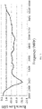
- FIG. 4 illustrates a test chart of a return loss of the external wideband antenna, where in the operating frequency band of the external wideband antenna, return losses are all lower than -5 dB, which can meet requirements of practical applications.
Landscapes
- Waveguide Aerials (AREA)
- Details Of Aerials (AREA)
Abstract
Description
- This application claims priority to
Chinese Patent Application No. 202010065923.0, filed January 20, 2020 Chinese Patent Application No. 202020143172.5, filed January 20, 2020 - This application relates to the field of wireless communication, and in particular, to an external wideband antenna and a wireless communication device.
- Compared with a second generation communication system, a third generation mobile communication system, and a fourth generation communication technology of long term evolution (LTE) system, fifth-generation mobile communication technology (5G for short) has higher wireless transmission speed and higher transmission quality, which can provide richer and faster wireless multimedia services, and enable users to have a better mobile broadband Internet experience.
- 5G mobile communication devices need to be compatible with fourth-generation mobile communication systems such as frequency division duplex (FDD), time division duplex (TDD), and wireless fidelity (Wi-Fi) communication systems such as Wi-Fi 2.4G and Wi-Fi 5G. As such, as an antenna device for emitting and receiving radio signals in the mobile communication device, it needs to be designed to meet requirements in multi-frequency and operating bandwidth of systems such as Wi-Fi 2.4G, Wi-Fi 5G, FDD, TDD, N77, N78, and N79.
- An external wideband antenna and a wireless communication device are provided in the disclosure to solve a technical problem that multi-band and wide-band performances of antennas in the related art needs to be improved.
- The above problem is solved by the disclosure with accordance to technical solutions described hereinafter.
- An external wideband antenna includes a radio frequency (RF) coaxial cable, and a first antenna body and a second antenna body which are electrically connected with the RF coaxial cable respectively. An outer contour of the first antenna body and an outer contour of the second antenna body cooperate to define a tapered slot.
- Preferably, the outer contour of the first antenna body is in a shape of ellipse, and part of the second antenna body close to the outer contour of the first antenna body is in a shape of ellipse, an elliptical outer contour of the first antenna body and an elliptical outer contour of the second antenna body cooperate to define the tapered slot; and/or at least one of the first antenna body or the second antenna body has a tapered outer contour; and/or at least one of the first antenna body or the second antenna body is in axisymmetric structure.
- Preferably, the first antenna body is electrically connected with an inner conductor of the RF coaxial cable. The second antenna body is grounded and electrically connected with an outer conductor of the RF coaxial cable.
- Preferably, the external wideband antenna further includes a feeding unit for connecting the first antenna body and the inner conductor.
- Preferably, the feeding unit comprises a patch component for adjusting antenna impedance.
- Preferably, the patch component comprises a Zero-Ohm resistor; or the patch component comprises at least one of a capacitor or an inductor.
- Preferably, the external wideband antenna further includes a dielectric substrate, and the first antenna body and the second antenna body are attached to the dielectric substrate.
- Preferably, the dielectric substrate is made of epoxy resin; and/or the dielectric substrate has a length ranging from 65 mm to 75 mm and a width ranging from 15 mm to 25 mm.
- Preferably, the external wideband antenna covers a first frequency band in a half-wavelength resonance mode, and covers a second frequency band in a full-wavelength resonance mode.
- Preferably, the first frequency band ranges from 2300 MHz to 4300 MHz; and/or the second frequency band ranges from 4300 MHz to 6300 MHz.
- A wireless communication device includes the external wideband antenna described in any of the above implementations.
- The disclosure has the following positive progressive effects. In the external wideband antenna provided the disclosure, the outer contour of the first antenna body and the outer contour of the second antenna body cooperate to define the tapered slot, which facilitates generation of a strong coupling current, and in turn a broadening of antenna bandwidth. As such, multiple frequency bands can be supported, which allows the wireless communication device using the external wideband antenna to compatible with multiple frequency bands of various communication systems.
-
-
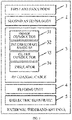
FIG. 1 is a schematic block diagram of an external wideband antenna provided according toimplementation 1 of the disclosure. -
FIG. 2 is a schematic cross-sectional view of a radio frequency (RF) coaxial cable in the external wideband antenna provided according toimplementation 1 of the disclosure. -
FIG. 3 is a schematic structural diagram of the external wideband antenna provided according toimplementation 1 of the disclosure. -
FIG. 4 is a test chart of a return loss of the external wideband antenna provided inFIG. 3 . - The disclosure is further described hereinafter with reference to implementations, but the disclosure is not therefore limited to the scope of the described implementations.
- An external wideband antenna is provided in this implementation. Referring to
FIG. 1 , the external wideband antenna in this implementation includes afirst antenna body 1, asecond antenna body 2, and a radio frequency (RF)coaxial cable 3. - In this implementation, the
first antenna body 1 and thesecond antenna body 2 are electrically connected with the RFcoaxial cable 3, respectively. Referring toFIG. 2 , the RFcoaxial cable 3 includes aninner conductor 31, anintermediate medium 32, anouter conductor 33, and an insulator 34 arranged in sequence from inside to outside. Specifically, in this implementation, the RFcoaxial cable 3 is used to introduce wired RF signals. Thefirst antenna body 1 is electrically connected with theinner conductor 31 of the RFcoaxial cable 3. Thesecond antenna body 2 is grounded and electrically connected with theouter conductor 33 of the RFcoaxial cable 3. - In this implementation, an outer contour of the
first antenna body 1 and an outer contour of thesecond antenna body 2 cooperate to define a tapered slot, which facilitates generation of a strong coupling current, so that a resonant frequency band of the antenna is widened, and thus a larger frequency range can be covered. As an example, in the tapered slot, an interval between the first antenna body and the second antenna body changes smoothly without a sudden change. - Further, in this implementation, the
first antenna body 1 may include a tapered outer contour which is beneficial to widening antenna bandwidth, and thesecond antenna body 2 may also include a tapered outer contour which is beneficial to widening the antenna bandwidth, such that thefirst antenna body 1 and thesecond antenna body 2 cooperate to define the tapered slot. - Further, in this implementation, the outer contour of the
first antenna body 1 may be in a shape of ellipse, and part of the outer contour of thesecond antenna body 2 close to thefirst antenna body 1 may be in a shape of ellipse. In an implementation, an elliptical outer contour of thefirst antenna body 1 and an elliptical outer contour of thesecond antenna body 2 cooperate to define the tapered slot. It should be understood that, in this implementation, the outer contours of thefirst antenna body 1 and thesecond antenna body 2 are not limited to the above-mentioned elliptical shapes, but may be in any shapes through which a tapered slot can be defined, where the tapered slot is beneficial to widening the antenna bandwidth. - Further, in this implementation, each of the
first antenna body 1 and thesecond antenna body 2 may be in axisymmetric structure. For example, thefirst antenna body 1 may be elliptical, and thesecond antenna body 2 may be saddle-shaped. Furthermore, the RFcoaxial cable 3 can be arranged on a symmetry axis of thefirst antenna body 1, or a symmetry axis of thesecond antenna body 2. As an example, the symmetry axis of thefirst antenna body 1 can be coincident with the symmetry axis of thesecond antenna body 2. - Referring to
FIG. 1 , in this implementation, the external wideband antenna can also include afeeding unit 4. Specifically, thefeeding unit 4 can be used to connect thefirst antenna body 1 and theinner conductor 31 of the RFcoaxial cable 3. As an example, thefeeding unit 4 may include a patch component for adjusting antenna impedance. Further, the patch component can include a Zero-Ohm resistor. The Zero-Ohm resistor can be replaced with other components when performance of the external wideband antenna provided in this implementation needs to be adjusted. - For example, when the resonant frequency band of the external wideband antenna needs to be shifted towards a low frequency, the Zero-Ohm resistor can be replaced with other components such as an inductor (whose inductance can be customized according to practical applications). When the resonant frequency band of the external wideband antenna needs to be shifted towards a high frequency, the Zero-Ohm resistor can be replaced with other components such as a capacitor (whose capacitance can be customized according to practical applications). For another example, when it needs to adjust the antenna impedance in a specific frequency band to improve antenna efficiency of the external wideband antenna in this specific frequency band, the Zero-Ohm resistor can be replaced with components such as an inductor (whose inductance can be customized according to practical applications) and a capacitor (whose capacitance can be customized according to practical applications).
- Referring to
FIG. 1 , in this implementation, the external wideband antenna can also include adielectric substrate 5. Specifically, thedielectric substrate 5 may be made of epoxy resin. Thefirst antenna body 1 and thesecond antenna body 2 may be attached to thedielectric substrate 5. On the one hand, thedielectric substrate 5 can serve as a support for thefirst antenna body 1, thesecond antenna body 2, the RFcoaxial cable 3, etc. On the other hand, with aid of thedielectric substrate 5, a dielectric constant is increased, which can achieve a lower resonant frequency under the premise of the same antenna size. Thus, in this implementation, a desired resonant frequency can be achieved with a smaller antenna size. Specifically, in this implementation, thedielectric substrate 5 may have a length ranging from 65 mm to 75 mm and a width ranging from 15 mm to 25 mm. -
FIG. 3 is a schematic structural diagram of the external wideband antenna provided according to this implementation. In an example, the external wideband antenna has a size of 70 mm∗20 mm, that is, thedielectric substrate 5 has a size of 70 mm∗20 mm. Thefirst antenna body 1 is elliptical. Thesecond antenna body 2 is saddle-shaped. Thefirst antenna body 1 and thesecond antenna body 2 are attached to thedielectric substrate 5. The symmetry axis of thefirst antenna body 1 is coincident with the symmetry axis of thesecond antenna body 2. The outer contour of thesecond antenna body 2 is recessed at a part close to thefirst antenna body 1. A recessed part of thesecond antenna body 2 and the outer contour of thefirst antenna body 1 cooperate to define the tapered slot. The RFcoaxial cable 3 for introducing external wired RF signals is disposed on a line where the symmetry axes of thefirst antenna body 1 and thesecond antenna body 2 are located. Further, theinner conductor 31 of the RFcoaxial cable 3 is electrically connected with thefirst antenna body 1, and theouter conductor 33 is grounded and electrically connected with thesecond antenna body 2. - In this implementation, based on the external wideband antenna provided in
FIG. 3 , a frequency band with a minimum value of 2300 MHz and a maximum value of 4000 MHz can be covered in a half-wavelength resonance mode, and a frequency band with a minimum value of 4000 MHz and a maximum value of 6300 MHz can be covered in a full-wavelength resonance mode. Thus, the external wideband antenna has an operating frequency band with a minimum value of 2300 MHz and a maximum value of 6300 MHz, such that the wireless communication device using the broadband location antenna provided in this implementation can be applied to multiple frequency bands such as Wi-Fi 2.4G, Wi-Fi 5G, FDD, TDD, N77, N78, and N79. Further,FIG. 4 illustrates a test chart of a return loss of the external wideband antenna, where in the operating frequency band of the external wideband antenna, return losses are all lower than -5 dB, which can meet requirements of practical applications. - In this implementation, a dipole antenna is optimized, where the first antenna body has a tapered outer contour, which is beneficial to widening the antenna bandwidth. In addition, the outer contour of the first antenna body and the outer contour of the second antenna body define the tapered slot, which is beneficial to further widening the antenna bandwidth. As such, multiple frequency bands can be supported, which allows the wireless communication device using the external wideband antenna to compatible with multiple frequency bands of various communication systems.
- A wireless communication device is provided in this implementation, where the wireless communication device includes the external wideband antenna provided in
implementation 1. The wireless communication device may include but is not limited to mobile terminals such as mobile phones, tablet computers, notebook computers, and e-books. - Since the external wideband antenna provided in
implementation 1 can support multiple frequency bands, the wireless communication device provided in this implementation can be compatible with multiple frequency bands of various communication systems, and can meet requirements for multi-frequency and broadband. - Those skilled in the art should understand that the implementations of the disclosure described above are merely exemplary, and the protection scope of the disclosure is defined by the appended claims. Various improvements and modifications can be made without departing from the principle of the disclosure to those skilled in the art, and the improvement and the modification are also considered as the protection scope of the disclosure.
Claims (11)
- An external wideband antenna, comprising:a radio frequency (RF) coaxial cable; anda first antenna body and a second antenna body which are electrically connected with the RF coaxial cable respectively, wherein an outer contour of the first antenna body and an outer contour of the second antenna body cooperate to define a tapered slot.
- The external wideband antenna of claim 1, whereinthe outer contour of the first antenna body is in a shape of ellipse, and part of the second antenna body close to the outer contour of the first antenna body is in a shape of ellipse;an elliptical outer contour of the first antenna body and an elliptical outer contour of the second antenna body cooperate to define the tapered slot; and/orat least one of the first antenna body or the second antenna body has a tapered outer contour; and/orat least one of the first antenna body or the second antenna body is in axisymmetric structure.
- The external wideband antenna of claim 1, whereinthe first antenna body is electrically connected with an inner conductor of the RF coaxial cable; andthe second antenna body is grounded and electrically connected with an outer conductor of the RF coaxial cable.
- The external wideband antenna of claim 3, wherein the external wideband antenna further comprises a feeding unit for connecting the first antenna body and the inner conductor.
- The external wideband antenna of claim 4, wherein the feeding unit comprises a patch component for adjusting antenna impedance.
- The external wideband antenna of claim 5, whereinthe patch component comprises a Zero-Ohm resistor; orthe patch component comprises at least one of a capacitor or an inductor.
- The external wideband antenna of claim 1, wherein the external wideband antenna further comprises a dielectric substrate, and the first antenna body and the second antenna body are attached to the dielectric substrate.
- The external wideband antenna of claim 7, whereinthe dielectric substrate is made of epoxy resin; and/orthe dielectric substrate has a length ranging from 65 mm to 75 mm and a width ranging from 15 mm to 25 mm.
- The external wideband antenna of claim 1, wherein the external wideband antenna covers a first frequency band in a half-wavelength resonance mode, and covers a second frequency band in a full-wavelength resonance mode.
- The external wideband antenna of claim 9, whereinthe first frequency band ranges from 2300 MHz to 4300 MHz; and/orthe second frequency band ranges from 4300 MHz to 6300 MHz.
- A wireless communication device, comprising the external wideband antenna of any of claims 1-10.
Applications Claiming Priority (3)
| Application Number | Priority Date | Filing Date | Title |
|---|---|---|---|
| CN202010065923.0A CN111162383A (en) | 2020-01-20 | 2020-01-20 | Broadband external antenna and wireless communication equipment |
| CN202020143172.5U CN211320331U (en) | 2020-01-20 | 2020-01-20 | Broadband external antenna and wireless communication equipment |
| PCT/CN2021/076297 WO2021148051A1 (en) | 2020-01-20 | 2021-02-09 | Broadband external antenna and wireless communication device |
Publications (2)
| Publication Number | Publication Date |
|---|---|
| EP4106104A1 true EP4106104A1 (en) | 2022-12-21 |
| EP4106104A4 EP4106104A4 (en) | 2024-02-28 |
Family
ID=76992889
Family Applications (1)
| Application Number | Title | Priority Date | Filing Date |
|---|---|---|---|
| EP21743739.1A Withdrawn EP4106104A4 (en) | 2020-01-20 | 2021-02-09 | EXTERNAL BROADBAND ANTENNA AND WIRELESS COMMUNICATION DEVICE |
Country Status (3)
| Country | Link |
|---|---|
| US (1) | US12237593B2 (en) |
| EP (1) | EP4106104A4 (en) |
| WO (1) | WO2021148051A1 (en) |
Family Cites Families (16)
| Publication number | Priority date | Publication date | Assignee | Title |
|---|---|---|---|---|
| AU2001282867A1 (en) * | 2000-08-07 | 2002-02-18 | Xtremespectrum, Inc. | Electrically small planar uwb antenna apparatus and system thereof |
| TWI267230B (en) * | 2004-06-15 | 2006-11-21 | Lin Ting Yu | Ultra wide band planner volcano smoke antenna |
| TWI245455B (en) * | 2005-02-05 | 2005-12-11 | Ind Tech Res Inst | Ultra-wideband antenna |
| JP4705537B2 (en) * | 2006-03-30 | 2011-06-22 | 富士通コンポーネント株式会社 | Antenna device and manufacturing method thereof |
| US8866691B2 (en) * | 2007-04-20 | 2014-10-21 | Skycross, Inc. | Multimode antenna structure |
| JP2008271468A (en) * | 2007-04-25 | 2008-11-06 | Toshiba Corp | Antenna device |
| CN101409383A (en) * | 2008-11-25 | 2009-04-15 | 东南大学 | Ultra-wideband beam-shaped antenna |
| US8576125B2 (en) * | 2009-10-30 | 2013-11-05 | Digi International Inc. | Planar wideband antenna |
| US20120154221A1 (en) * | 2010-12-20 | 2012-06-21 | Mccorkle John W | Electrically small octave bandwidth non-dispersive uni-directional antenna |
| CN102856629B (en) * | 2012-08-31 | 2015-09-23 | 惠州Tcl移动通信有限公司 | A kind of Three-in-one antenna device of cell phone |
| US10734726B2 (en) * | 2014-11-12 | 2020-08-04 | Nagasaki University | Wideband planar circularly polarized antenna and antenna device |
| CN107293853A (en) * | 2017-06-19 | 2017-10-24 | 泰姆瑞技术(深圳)有限公司 | A kind of dual polarized antenna |
| US10186769B1 (en) * | 2017-07-20 | 2019-01-22 | Apple Inc. | Electronic device with shared control and power lines for antenna tuning circuits |
| CN209282404U (en) * | 2019-01-03 | 2019-08-20 | 深圳市中冀联合技术股份有限公司 | A kind of miniaturization dual polarization ultra-wideband antenna with stabilising direction figure |
| CN115152091A (en) * | 2020-02-26 | 2022-10-04 | 日本板硝子株式会社 | glass antenna |
| US11715881B2 (en) * | 2021-12-09 | 2023-08-01 | United States Of America As Represented By The Secretary Of The Navy | Blade antenna with ultra-uniform azimuthal gain patterns over a wide bandwidth |
-
2021
- 2021-02-09 EP EP21743739.1A patent/EP4106104A4/en not_active Withdrawn
- 2021-02-09 WO PCT/CN2021/076297 patent/WO2021148051A1/en not_active Ceased
-
2022
- 2022-07-19 US US17/868,751 patent/US12237593B2/en active Active
Also Published As
| Publication number | Publication date |
|---|---|
| US12237593B2 (en) | 2025-02-25 |
| WO2021148051A1 (en) | 2021-07-29 |
| EP4106104A4 (en) | 2024-02-28 |
| US20220368023A1 (en) | 2022-11-17 |
Similar Documents
| Publication | Publication Date | Title |
|---|---|---|
| US8884833B2 (en) | Broadband monopole antenna with dual radiating structures | |
| AU2018423290B2 (en) | Antenna system and terminal device | |
| US6515625B1 (en) | Antenna | |
| US5923305A (en) | Dual-band helix antenna with parasitic element and associated methods of operation | |
| CA2720512C (en) | Compact multiple-band antenna for wireless devices | |
| CN112751203A (en) | Antenna assembly and electronic equipment | |
| WO2014117738A1 (en) | Antenna apparatus and terminal device | |
| US7403161B2 (en) | Multiband antenna in a communication device | |
| US12388180B2 (en) | Antenna structure and wireless communication device having same | |
| CN209896263U (en) | Multi-band antenna based on composite left-right-hand transmission line | |
| US12237593B2 (en) | External wideband antenna and wireless communication device | |
| US9059513B2 (en) | Multiband antenna structure | |
| CN211320331U (en) | Broadband external antenna and wireless communication equipment | |
| CN108847525B (en) | A compact multi-band antenna | |
| US10629992B2 (en) | Antenna system for matching an impedance | |
| US11996638B2 (en) | Antenna system | |
| CN113659318B (en) | Millimeter wave antenna and terminal | |
| CN111162383A (en) | Broadband external antenna and wireless communication equipment | |
| EP4246722A1 (en) | Antenna | |
| CN110401023B (en) | Ultra-wideband V/UHF miniaturized omnidirectional antenna with notch characteristic | |
| CN222851661U (en) | Omnidirectional antenna | |
| JP7243966B2 (en) | Antenna system and terminal device | |
| CN222915143U (en) | Antenna for foldable device and foldable device | |
| CN107026323A (en) | It is a kind of to minimize the method that signal is sent on 11 frequency range antenna for mobile phone | |
| CN118249089A (en) | Antenna module, electronic equipment and control method |
Legal Events
| Date | Code | Title | Description |
|---|---|---|---|
| STAA | Information on the status of an ep patent application or granted ep patent |
Free format text: STATUS: THE INTERNATIONAL PUBLICATION HAS BEEN MADE |
|
| PUAI | Public reference made under article 153(3) epc to a published international application that has entered the european phase |
Free format text: ORIGINAL CODE: 0009012 |
|
| STAA | Information on the status of an ep patent application or granted ep patent |
Free format text: STATUS: REQUEST FOR EXAMINATION WAS MADE |
|
| 17P | Request for examination filed |
Effective date: 20220820 |
|
| AK | Designated contracting states |
Kind code of ref document: A1 Designated state(s): AL AT BE BG CH CY CZ DE DK EE ES FI FR GB GR HR HU IE IS IT LI LT LU LV MC MK MT NL NO PL PT RO RS SE SI SK SM TR |
|
| XX | Miscellaneous (additional remarks) |
Free format text: A REQUEST FOR RESTORATION OF THE RIGHT OF PRIORITY UNDER RULE 49TER.2 PCT IS PENDING BEFORE THE EPO AS DESIGNATED OFFICE. |
|
| DAV | Request for validation of the european patent (deleted) | ||
| DAX | Request for extension of the european patent (deleted) | ||
| REG | Reference to a national code |
Ref country code: DE Ref legal event code: R079 Free format text: PREVIOUS MAIN CLASS: H01Q0001380000 Ipc: H01Q0009400000 |
|
| A4 | Supplementary search report drawn up and despatched |
Effective date: 20240125 |
|
| RIC1 | Information provided on ipc code assigned before grant |
Ipc: H01Q 13/10 20060101ALI20240119BHEP Ipc: H01Q 5/357 20150101ALI20240119BHEP Ipc: H01Q 9/40 20060101AFI20240119BHEP |
|
| STAA | Information on the status of an ep patent application or granted ep patent |
Free format text: STATUS: THE APPLICATION HAS BEEN WITHDRAWN |
|
| 18W | Application withdrawn |
Effective date: 20250221 |