EP4106081A1 - Ventilation device for pouch-type secondary battery and battery module including the same - Google Patents
Ventilation device for pouch-type secondary battery and battery module including the same Download PDFInfo
- Publication number
- EP4106081A1 EP4106081A1 EP22179753.3A EP22179753A EP4106081A1 EP 4106081 A1 EP4106081 A1 EP 4106081A1 EP 22179753 A EP22179753 A EP 22179753A EP 4106081 A1 EP4106081 A1 EP 4106081A1
- Authority
- EP
- European Patent Office
- Prior art keywords
- frame
- vent
- pouch
- battery
- ventilation device
- Prior art date
- Legal status (The legal status is an assumption and is not a legal conclusion. Google has not performed a legal analysis and makes no representation as to the accuracy of the status listed.)
- Pending
Links
Images




Classifications
-
- H—ELECTRICITY
- H01—ELECTRIC ELEMENTS
- H01M—PROCESSES OR MEANS, e.g. BATTERIES, FOR THE DIRECT CONVERSION OF CHEMICAL ENERGY INTO ELECTRICAL ENERGY
- H01M50/00—Constructional details or processes of manufacture of the non-active parts of electrochemical cells other than fuel cells, e.g. hybrid cells
- H01M50/30—Arrangements for facilitating escape of gases
-
- H—ELECTRICITY
- H01—ELECTRIC ELEMENTS
- H01M—PROCESSES OR MEANS, e.g. BATTERIES, FOR THE DIRECT CONVERSION OF CHEMICAL ENERGY INTO ELECTRICAL ENERGY
- H01M10/00—Secondary cells; Manufacture thereof
- H01M10/60—Heating or cooling; Temperature control
- H01M10/61—Types of temperature control
- H01M10/613—Cooling or keeping cold
-
- H—ELECTRICITY
- H01—ELECTRIC ELEMENTS
- H01M—PROCESSES OR MEANS, e.g. BATTERIES, FOR THE DIRECT CONVERSION OF CHEMICAL ENERGY INTO ELECTRICAL ENERGY
- H01M10/00—Secondary cells; Manufacture thereof
- H01M10/60—Heating or cooling; Temperature control
- H01M10/64—Heating or cooling; Temperature control characterised by the shape of the cells
- H01M10/647—Prismatic or flat cells, e.g. pouch cells
-
- H—ELECTRICITY
- H01—ELECTRIC ELEMENTS
- H01M—PROCESSES OR MEANS, e.g. BATTERIES, FOR THE DIRECT CONVERSION OF CHEMICAL ENERGY INTO ELECTRICAL ENERGY
- H01M10/00—Secondary cells; Manufacture thereof
- H01M10/60—Heating or cooling; Temperature control
- H01M10/65—Means for temperature control structurally associated with the cells
- H01M10/655—Solid structures for heat exchange or heat conduction
- H01M10/6556—Solid parts with flow channel passages or pipes for heat exchange
-
- H—ELECTRICITY
- H01—ELECTRIC ELEMENTS
- H01M—PROCESSES OR MEANS, e.g. BATTERIES, FOR THE DIRECT CONVERSION OF CHEMICAL ENERGY INTO ELECTRICAL ENERGY
- H01M50/00—Constructional details or processes of manufacture of the non-active parts of electrochemical cells other than fuel cells, e.g. hybrid cells
- H01M50/10—Primary casings; Jackets or wrappings
- H01M50/102—Primary casings; Jackets or wrappings characterised by their shape or physical structure
- H01M50/105—Pouches or flexible bags
-
- H—ELECTRICITY
- H01—ELECTRIC ELEMENTS
- H01M—PROCESSES OR MEANS, e.g. BATTERIES, FOR THE DIRECT CONVERSION OF CHEMICAL ENERGY INTO ELECTRICAL ENERGY
- H01M50/00—Constructional details or processes of manufacture of the non-active parts of electrochemical cells other than fuel cells, e.g. hybrid cells
- H01M50/10—Primary casings; Jackets or wrappings
- H01M50/183—Sealing members
- H01M50/186—Sealing members characterised by the disposition of the sealing members
-
- H—ELECTRICITY
- H01—ELECTRIC ELEMENTS
- H01M—PROCESSES OR MEANS, e.g. BATTERIES, FOR THE DIRECT CONVERSION OF CHEMICAL ENERGY INTO ELECTRICAL ENERGY
- H01M50/00—Constructional details or processes of manufacture of the non-active parts of electrochemical cells other than fuel cells, e.g. hybrid cells
- H01M50/20—Mountings; Secondary casings or frames; Racks, modules or packs; Suspension devices; Shock absorbers; Transport or carrying devices; Holders
- H01M50/204—Racks, modules or packs for multiple batteries or multiple cells
- H01M50/207—Racks, modules or packs for multiple batteries or multiple cells characterised by their shape
- H01M50/211—Racks, modules or packs for multiple batteries or multiple cells characterised by their shape adapted for pouch cells
-
- H—ELECTRICITY
- H01—ELECTRIC ELEMENTS
- H01M—PROCESSES OR MEANS, e.g. BATTERIES, FOR THE DIRECT CONVERSION OF CHEMICAL ENERGY INTO ELECTRICAL ENERGY
- H01M50/00—Constructional details or processes of manufacture of the non-active parts of electrochemical cells other than fuel cells, e.g. hybrid cells
- H01M50/20—Mountings; Secondary casings or frames; Racks, modules or packs; Suspension devices; Shock absorbers; Transport or carrying devices; Holders
- H01M50/233—Mountings; Secondary casings or frames; Racks, modules or packs; Suspension devices; Shock absorbers; Transport or carrying devices; Holders characterised by physical properties of casings or racks, e.g. dimensions
- H01M50/242—Mountings; Secondary casings or frames; Racks, modules or packs; Suspension devices; Shock absorbers; Transport or carrying devices; Holders characterised by physical properties of casings or racks, e.g. dimensions adapted for protecting batteries against vibrations, collision impact or swelling
-
- H—ELECTRICITY
- H01—ELECTRIC ELEMENTS
- H01M—PROCESSES OR MEANS, e.g. BATTERIES, FOR THE DIRECT CONVERSION OF CHEMICAL ENERGY INTO ELECTRICAL ENERGY
- H01M50/00—Constructional details or processes of manufacture of the non-active parts of electrochemical cells other than fuel cells, e.g. hybrid cells
- H01M50/30—Arrangements for facilitating escape of gases
- H01M50/308—Detachable arrangements, e.g. detachable vent plugs or plug systems
-
- H—ELECTRICITY
- H01—ELECTRIC ELEMENTS
- H01M—PROCESSES OR MEANS, e.g. BATTERIES, FOR THE DIRECT CONVERSION OF CHEMICAL ENERGY INTO ELECTRICAL ENERGY
- H01M50/00—Constructional details or processes of manufacture of the non-active parts of electrochemical cells other than fuel cells, e.g. hybrid cells
- H01M50/30—Arrangements for facilitating escape of gases
- H01M50/35—Gas exhaust passages comprising elongated, tortuous or labyrinth-shaped exhaust passages
- H01M50/358—External gas exhaust passages located on the battery cover or case
-
- H—ELECTRICITY
- H01—ELECTRIC ELEMENTS
- H01M—PROCESSES OR MEANS, e.g. BATTERIES, FOR THE DIRECT CONVERSION OF CHEMICAL ENERGY INTO ELECTRICAL ENERGY
- H01M50/00—Constructional details or processes of manufacture of the non-active parts of electrochemical cells other than fuel cells, e.g. hybrid cells
- H01M50/50—Current conducting connections for cells or batteries
- H01M50/502—Interconnectors for connecting terminals of adjacent batteries; Interconnectors for connecting cells outside a battery casing
- H01M50/503—Interconnectors for connecting terminals of adjacent batteries; Interconnectors for connecting cells outside a battery casing characterised by the shape of the interconnectors
-
- H—ELECTRICITY
- H01—ELECTRIC ELEMENTS
- H01M—PROCESSES OR MEANS, e.g. BATTERIES, FOR THE DIRECT CONVERSION OF CHEMICAL ENERGY INTO ELECTRICAL ENERGY
- H01M50/00—Constructional details or processes of manufacture of the non-active parts of electrochemical cells other than fuel cells, e.g. hybrid cells
- H01M50/50—Current conducting connections for cells or batteries
- H01M50/502—Interconnectors for connecting terminals of adjacent batteries; Interconnectors for connecting cells outside a battery casing
- H01M50/507—Interconnectors for connecting terminals of adjacent batteries; Interconnectors for connecting cells outside a battery casing comprising an arrangement of two or more busbars within a container structure, e.g. busbar modules
-
- Y—GENERAL TAGGING OF NEW TECHNOLOGICAL DEVELOPMENTS; GENERAL TAGGING OF CROSS-SECTIONAL TECHNOLOGIES SPANNING OVER SEVERAL SECTIONS OF THE IPC; TECHNICAL SUBJECTS COVERED BY FORMER USPC CROSS-REFERENCE ART COLLECTIONS [XRACs] AND DIGESTS
- Y02—TECHNOLOGIES OR APPLICATIONS FOR MITIGATION OR ADAPTATION AGAINST CLIMATE CHANGE
- Y02E—REDUCTION OF GREENHOUSE GAS [GHG] EMISSIONS, RELATED TO ENERGY GENERATION, TRANSMISSION OR DISTRIBUTION
- Y02E60/00—Enabling technologies; Technologies with a potential or indirect contribution to GHG emissions mitigation
- Y02E60/10—Energy storage using batteries
Definitions
- the present invention relates to a ventilation device for a pouch-type secondary battery and a battery module including the same.
- a secondary battery which can be charged and discharged repeatedly has been widely employed as a power source of a mobile electronic device such as a camcorder, a mobile phone, a laptop computer, etc., according to developments of information and display technologies. Recently, a battery pack including the secondary battery is being developed and applied to a power source of an eco-friendly vehicle.
- the secondary battery includes, e.g., a lithium secondary battery, a nickel-cadmium battery, a nickel-hydrogen battery, etc.
- the lithium secondary battery is highlighted due to high operational voltage and energy density per unit weight, a high charging rate, a compact dimension, etc.
- the lithium secondary battery may include an electrode assembly including a cathode, an anode and a separation layer (separator), and an electrolyte immersing the electrode assembly.
- the lithium secondary battery may further include an outer case having, e.g., a pouch shape for accommodating the electrode assembly and the electrolyte.
- a gas may be continuously generated at an inside of the battery to increases an internal pressure of the pouch. If the internal pressure is increased beyond a tolerable critical value, a sealing portion at the weakest portion of the pouch may be damaged to cause a ventilation (hereinafter, referred to as a vent).
- the vent may occur randomly in the pouch, vent generation portions may not be easily predicted.
- a lamination film is welded at a sealing portion of a pouch-type battery to induce a directional venting of a gas generated in the pouch.
- sufficient venting inducing effects and battery cell stability may not be provided.
- a ventilation device for a pouch-type secondary battery having improved vent control properties.
- a battery module having improved vent control properties.
- a ventilation device for a pouch-type secondary battery includes a frame comprising a first frame and a second frame, and a connector connecting the first frame and the second frame to each other and having a slit portion formed therein.
- Each of the first frame and the second frame has a facing surface to each other, and at least one of the first frame and the second frame includes a vent guiding portion recessed from the facing surface.
- a vent control portion is formed as a space between the first frame and the second frame to be connected to the vent guiding portion.
- the connector may extend from a rear surface of the first frame to be connected to a rear surface of the second frame
- the first frame may have a first frame facing surface facing the second frame and a first vent guiding surface recessed from the first frame facing surface
- the second frame may haves a second frame facing surface facing the first frame and a second vent guiding surface recessed from the second frame facing surface
- the vent guiding portion may be formed between the first vent guiding surface and the second vent guiding surface.
- the slit portion may extend between the first frame and the second frame, and the vent guiding portion may be adjacent to one end of the slit portion and may be opened to an outside of the frame.
- the vent guiding portion may include a venting groove.
- the vent guiding portion may include a venting hole.
- an inner shape of the venting hole may include at least one of a cylindrical shape, a semi-cylindrical shape, a funnel shape and a polygonal pillar shape.
- an average diameter of each of the cylindrical shape, the semi-cylindrical shape and the funnel shape may be from 1 mm ⁇ to 500 mm ⁇ .
- a cap may be fitted to the vent guiding portion.
- the cap may include a material having a ductility greater than that of a material of the frame.
- the slit portion may have a sub-venting hole having the same shape as that of the vent guiding portion at a position corresponding to the vent guiding portion.
- an interval between the first frame and the second frame may be from 0.1 mm to 10 mm.
- a battery module includes a plurality of battery cells stacked on each other, each of the plurality of battery cells including an electrode lead, and a bus bar assembly coupled to an end from which the electrode leads of the plurality of battery cells are drawn out to connect the plurality of battery cells to each other.
- the bus bar assembly includes a main frame including a slit portion from which the electrode leads of the plurality of battery cells are drawn out, a bus bar mounted on an outer surface of the main frame to electrically connect the electrode leads drawn out through the slit portion to each other, and a plurality of inner frames spaced apart from each other on an inner surface of the main frame to guide the electrode lead to the slit portion.
- the plurality of inner frames include a first inner frame and a second inner frame neighboring each other, and the first inner frame includes a vent guiding portion recessed from a surface facing the second inner frame, and a vent control portion is formed as a space between the first inner frame and the second inner frame to be connected to the vent guiding portion.
- the first inner frame may have a first inner frame facing surface facing the second inner frame, and a first inner vent guiding surface recessed from the first inner frame facing surface.
- the second inner frame may have a second inner frame facing surface facing the first inner frame, and a second inner vent guiding surface recessed from the second inner frame facing surface.
- the vent guiding portion may be formed between the first inner vent guiding surface and the second inner vent guiding surface.
- the plurality of battery cells may each include an electrode assembly and a pouch for accommodating the electrode assembly.
- the pouch may include a sealing portion formed at an outside the electrode assembly, and the electrode lead and the sealing portion may be at least partially located in the vent control portion.
- At least a portion of the sealing portion may be in contact with at least a portion of the first inner frame facing surface and the second inner frame facing surface in the vent control portion.
- the sealing portion may include a side sealing portion sealing an end from which the electrode lead is drawn out, and a main sealing portion sealing a side from which the electrode lead is not drawn out.
- the main sealing portion may have a folding portion in which the pouch is folded at an edge thereof.
- a contact area of the side sealing portion with the first inner frame facing surface and the second inner frame facing surface is from 200 mm2 to 20,000 mm 2 .
- the vent guiding portion may be adjacent to one end of the slit portion and may be opened to an outside of at least one inner frame among the plurality of inner frames.
- an inner shape of the vent guiding portion may include at least one of a cylindrical shape, a semi-cylindrical shape, a funnel shape and a polygonal pillar shape.
- a cap may be fitted to the vent guiding portion.
- the cap may include a material having greater ductility than that of the plurality of inner frames.
- an interval between the plurality of inner frames may be from 0.1 mm to 10 mm.
- the slit portion may have a sub-venting hole having the same shape as that of the vent guiding portion at a position corresponding to the vent guiding portion.
- a vent caused by a gas generated at an inside of the pouch may be delayed.
- the gas may be induced in a specific direction to be discharged even when a vent occurs, so that damage or explosion of a battery cell may be prevented.
- a pouch expansion may be suppressed by a vent control portion of the ventilation device to prevent or delay the vent.
- the ventilation device for a pouch-type secondary battery may guide a direction of the gas to a vent guiding portion, so that a region or a time of the vent generation may be predicted.
- an additional device e.g., a venting unit
- productivity of the secondary battery or a battery module may be enhanced.
- a vent may be controlled to maintain stability even when a pressure at an inside of a battery pouch may be increased beyond an appropriate level. Accordingly, stability of the battery cell may be achieved and deterioration of a battery cell performance may be prevented.
- a ventilation device for a pouch-type secondary battery capable of reducing or delaying a gas generated in a battery cell.
- a battery module including the ventilation device is also provided.
- frame refers to an element of a ventilation device capable of controlling a direction of a gas generated in a battery cell in combination with a battery cell.
- a first frame and a second frame are designated merely to be distinguished from each other, and positions or orders thereof are not specifically limited by the terms “first” and "second.”
- FIG. 1 is a schematic perspective view illustrating a ventilation device for a pouch-type secondary battery in accordance with exemplary embodiments.
- L refers to a length direction from a left side to a right side, or from the right side to the left side of the first frame and the second frame
- H refers to a height direction upwardly or downwardly
- D refers to a thickness direction from a front face to a rear face or from the rear face to the front face
- h refers to an interval between the first frame and the second frame.
- an interval between the first frame and the second frame may be a sufficiently close distance by which, e.g., a portion of a cell pouch may be in contact with the first frame and the second frame when the battery cell is inserted between the first frame and the second frame.
- a ventilation device 100 for a pouch-type secondary battery may include a first frame 110, a second frame 120, and a connector 150 for connecting the first frame 110 and the second frame 120 with each other.
- the first frame 110 and the second frame 120 may face each other.
- the connector 150 may include a slit portion 151 extending between the first frame 110 and the second frame 120.
- the connector 150 and the slit portion 151 are indicated with dotted lines in consideration of the interval between the first frame 110 and the second frame 120.
- the "frames 110 and 120" used herein may refer to at least one of the first frame 110 and the second frame 120.
- the first frame 110 may include a first frame body 111
- the second frame 120 may include a second frame body 121.
- the first frame 110 may include a first frame facing surface 112 facing the second frame 120
- the second frame 120 may include a second frame facing surface 122 facing the first frame 110.
- the first frame 110 and the second frame 120 may be fixed and connected to each other by the connector 150.
- the connector 150 may extend from a rear surface of the first frame 110 to be connected to a rear surface of the second frame 120.
- the connector 150 may include, e.g., the slit portion 151.
- the slit portion 151 may extend between the first frame 110 and the second frame 120 such that an electrode lead of the battery cell may be inserted in a thickness direction of the first frame 110 and the second frame 120 when the battery cell is inserted into the ventilation device 100.
- a size or a length of the slit portion 151 may be appropriately adjusted within a range by which the electrode lead of the battery cell may be inserted.
- At least one of the first frame 110 and the second frame 120 may include a vent guiding portion 130 recessed at the facing surface. Further, a vent control portion 140 connected to the vent guiding portion 130 may be formed as a space formed between the first frame 110 and the second frame 120.
- the first frame 110 may include the first frame facing surface 112 facing the second frame 120 and a first vent guiding surface 131 formed by being recessed from the first frame facing surface 112.
- the second frame 120 may include the second frame facing surface 122 facing the first frame 110 and a second vent guiding surface 132 formed by being recessed from the second frame facing surface 122.
- the vent guiding portion 130 may be formed between the first vent guiding surface 131 and the second vent guiding surface 132.
- first vent guiding surface 131 recessed from the first frame facing surface 112 and the second vent guiding surface 132 recessed from the second frame facing surface 122 may face each other to form a venting groove or a venting hole as the vent guiding portion 130.
- a position at the frames 110 and 120 of the vent guiding portion 130 or a shape of the vent guiding portion 130 may be properly adjusted.
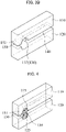
- FIGS. 2A to 2D and FIGS. 3A to 3B are schematic perspective views illustrating ventilation devices for a pouch-type secondary battery in accordance with some exemplary embodiments.
- the vent guiding portion 130 may be formed at an edge of the frames 110 and 120.
- the vent guiding portion 130 may be adjacent to one end of the slit portion 150 and may be opened to an outside of the frames 110 and 120.
- the vent guiding portion 130 may be formed at an inner region of the first frame 110 and the second frame 120.
- the vent guiding portion 130 may include a venting groove 135.
- the venting groove 135 may include a groove formed at a front surface of the first frame 110.
- the venting groove 135 may be recessed from the front surface of the first frame 110 and spaced apart from the rear surface of the first frame 110.
- the vent guiding portion 130 may include a venting hole 137.
- the venting hole 137 may be a hole or an opening formed at the front surface of the first frame 110.
- the venting hole 137 may be a hole extending from the front surface of the first frame 110 to the rear surface of the first frame 110.
- the venting groove 135 or the venting hole 137 may serve as a passage through which a gas may be discharged to the outside, when the battery cell is inserted between the first frame 110 and the second frame 120 and a vent occurs due to an increase of an internal pressure of the pouch during a battery operation.
- an inner shape of the venting hole 137 may include, e.g., at least one of a cylindrical shape, a semi-cylindrical shape, a funnel shape and a polygonal pillar shape.
- the inner shape of the venting hole 137 may be the cylinder shape, the semi-cylindrical shape or the funnel shape.
- the venting hole 137 may have the funnel shape.
- the venting hole 137 may have the funnel shape in which a width becomes narrower from the front surface to the rear surface of the frames 110 and 120.
- the venting hole 137 may have the funnel shape in which the width becomes wider from the front surface to the rear surface of the frames 110 and 120.
- venting hole 137 may have a triangular pillar shape or an octagonal pillar shape.
- a remainder space in which the pouch may be expanded when the gas is generated in the pouch may be provided by the vent guiding portion 130 serving as the venting groove or the venting hole.
- the gas may be induced to the vent guiding portion 130. Accordingly, the vent may be easily controlled or induced without additional components or equipment.
- an average diameter may be from 1 mm ⁇ to 500 mm ⁇ , preferably from 5 mm ⁇ to 100 mm ⁇ . In the above range, the gas induction and exhaustion to the vent guiding portion 130 may be promoted.
- FIG. 4 is a schematic perspective view illustrating a ventilation device for a pouch-type secondary battery in accordance with some exemplary embodiments.
- the venting guiding portion 130 may further include caps 115 and 125.
- a portion of the battery cell pouch e.g., a pouch sealing portion may be in contact with a first cap 115 and/or a second cap 125 in the vent guiding portion 130.
- the caps 115 and 125 may include a soft material that is more physically deformable than a material of the frames 110 and 120 is.
- the caps 115 and 125 when a pressure of a predetermined value or more is applied to the caps 115 and 125 in the height, thickness or length direction of the frames 110 and 120, the caps 115 and 125 may be separated from the frame 110 and 120.
- the caps 115 and 125 when a heat of a predetermined value or more is applied to the caps 115 and 125 in the height, thickness, or length direction of the frame 110 and 120, the caps 115 and 125 may be melted.
- the caps 115 and 125 may include a low melting point material.
- the caps 115 and 125 may include tin (Sn), zinc (Zn), lead (Pb), bismuth (Bi), indium (In), etc. Accordingly, the caps 115 and 125 may be transformed into a flowable state. Thus, a gas exhaust passage may be formed by the deformation of the caps 115 and 125.
- FIGS. 5A and 5B are schematic perspective views illustrating ventilation devices for a pouch-type secondary battery in accordance with some exemplary embodiments.
- the slit portion 151 may include a sub-venting hole 153 having substantially the same shape as that of the vent guiding portion 130 at a position corresponding to the vent guiding portion 130.
- a sub-venting hole 153 having substantially the same shape as that of the vent guiding portion 130 at a position corresponding to the vent guiding portion 130.
- the vent guiding portion 130 may be formed at an inside of the frames 110 and 120, and the sub-venting hole 153 may also be formed in the slit portion 151.
- the vent guiding portion 130 may be formed at one end of the frames 110 and 120, and the sub-venting hole 153 may also be formed at one end of the slit portion 151 to be opened to an outside of the connector 150.
- the sub-venting hole 153 may be formed at a position corresponding to the vent guiding portion 130, and may have a shape corresponding to that of the vent guiding portion 130, so that a structure more advantageous to a vent control may be provided.
- the vent control portion 140 may be provided as a space formed between the first frame 110 and the second frame 120, and may be connected to the vent guiding portion 130.
- the vent control portion 140 may be formed between the first frame 110 and the second frame 120 along the length direction designated as L of the frames 110 and 120, and may be connected to the vent guiding portion 130.
- a sealing portion of the pouch of the battery cell may be in contact with a surface of the frame 110 and 120 in the vent control portion 140.
- the interval between the frames 110 and 120 is illustrated as being relatively larger than an actual interval.
- the interval between the frames 110 and 120 may be a sufficiently small so that the portion of the battery cell may contact the surface of the frame when the battery cell is inserted between the frames 110 and 120.
- the gas when the gas is generated in the pouch, a space for an expansion of the pouch may be reduced, so that the pouch expansion may be suppressed. Accordingly, the generation of the vent may be interrupted or delayed.
- the interval between the first frame 110 and the second frame 120 may be from 0.1 mm to 10 mm.
- the interval between the first frame 110 and the second frame 120 is designated as h in FIG, 1 , and the interval h may be preferably from 2 mm to 5 mm.
- the battery cell may be inserted and fixed in the ventilation device 100 and the pouch expansion may be effectively suppressed during an operation of the battery cell.
- a length of each of the first frame 110 and the second frame 120 in the direction designated as L may be from 10 mm to 500 mm, a height in the direction designated as H may be from 1 mm to 50 mm, and a thickness in the direction designated as D may be from 1 mm to 50 mm.
- the length may be from 5 mm to 300 mm, the height may be from 5 mm to 30 mm, and the thickness may be from 5 mm to 30 mm.
- a size or a shape of the ventilation device may be property variously modified within a range in which the battery cell may be easily applied to the ventilation device 100, and a vent direction may be controlled by applying the battery cells to the ventilation device 100.
- the frames 110 and 120 may include a material having high rigidity and high elasticity to withstand physical and chemical forces applied from the outside. Further, the connector 150 may include the same material as that of the frames 110 and 120.
- the frames 110 and 120 may include a material having higher rigidity or elasticity than a material included in the caps to provide improved durability in harsh conditions.
- the frames 110 and 120 may include a plastic, a metal, a ceramic, or the like.
- the plastic may include a widely used plastic, an engineering plastic, etc.
- the metal may include aluminum, copper, iron, stainless steel, etc.
- the polymer may include a rubber, polyurethane foam, etc.
- first frame 110, the second frame 120 and the connector 150 may be integral with each other.
- a pouch-type battery cell unit may be implemented by inserting the battery cell into the above-described ventilation device for a pouch-type secondary battery.
- FIG. 6 is a schematic top plan view of a battery cell in accordance with exemplary embodiments.
- a battery cell 200 may include an electrode assembly 210 having an electrode lead 220 formed at one end thereof and a pouch 230 accommodating the electrode assembly 210.
- electrode lead 220 used herein may refer to at least one of the first electrode lead 221 and the second electrode lead 222.
- the pouch 230 may include a sealing portion 240 formed at an outside of the electrode assembly 210.
- the sealing portion 240 may include a side sealing portion 241 for sealing an end from which the electrode lead 220 is drawn out, and a main sealing portion 243 for sealing a side from which the electrode lead 220 is not drawn out.
- a folding portion 245 may be formed by folding the pouch 230 at an edge of the main sealing portion 243.
- the side sealing portion 241 may be a sealing portion located in a direction in which the electrode lead is drawn out of sealing portions formed at the outside of the electrode assembly.
- the main sealing portion 243 may be a sealing portion connected to the side sealing portion 241 and located in a direction in which the electrode lead is not drawn out.
- the folding portion 245 may refer to a structure in which the pouch extends at the edge of the main sealing portion 243 to be folded.
- an unnecessary space between adjacent battery cells may be reduced when assembling a battery module by forming the folding portion 243.
- the folding portion 243 may be formed to be smaller than a thickness of the electrode assembly and may not protrude.
- the adjacent battery cells may be disposed more closely to increase a volumetric efficiency of the battery module.
- FIG. 7 is a schematic perspective view illustrating a battery cell unit in accordance with exemplary embodiments.
- the battery cell 200 may be inserted into the ventilation device 100.
- the electrode lead 220 of the battery cell 200 may be inserted into the slit portion 151 of the ventilation device 100 from the front surface to the rear surface of the frames 110 and 120.
- portions of the electrode lead 220 and the sealing portion 240 of the battery cell 200 may be located in the vent control portion 140.
- the side sealing portion 241 may be located in the vent control portion 140 to be contact with the first frame facing surface 112 and the second frame facing surface 122.
- the sealing portion 240 of the pouch may contact the frame facing surfaces 112 and 122, so that expansion of the pouch may be suppressed by the frames 110 and 120 even when gas is generated in the pouch.
- the sealing portion 240 may be prevented from being disassembled due to the gas expansion, thereby suppressing or delaying occurrence of the vent.
- FIG. 8 is a schematic diagram for describing an operation mechanism of a battery cell unit in accordance with exemplary embodiments.
- the venting may be controlled by the vent control portion 140.
- the venting may be induced by the vent guiding portion 130.
- the region (A) of the vent control portion 140 may directly contact the first frame 110 and the second frame 120 to suppress an expansion of the sealing portion 240. Accordingly, a vent generation may be delayed or suppressed, and a vent control may be implemented.
- an expansion of the sealing portion 240 may be relatively allowed.
- the gas generated in the pouch 230 may be transferred to the region (B), and the pouch 230 may be expanded.
- the sealing portion 240 may be opened to cause an exhaustion of the gas to the outside.
- the gas generated in the pouch 230 may be exhausted through the vent guiding portion 130. Accordingly, damages or explosion of the battery cell may be prevented. Additionally, a direction of the gas exhaustion may be controlled by the vent guiding portion 130, so that a vent generation location may be easily predicted.
- the venting may be controlled to improve a durability to pressure. Accordingly, stability of the battery may be enhanced and deterioration of a battery performance may be prevented.
- FIG. 9 is a schematic perspective view illustrating a battery module in accordance with exemplary embodiments.
- the battery module may include the battery cell units applied to the ventilation device 100 as described above.
- a battery module 400 may include a plurality of the battery cells 200.
- the plurality of the battery cells 200 may be stacked by a surface contact with each other.
- the plurality of the battery cells 200 stacked on each other may form a battery stack, and the plurality of the battery cells 200 may be electrically connected to each other by a bus bar assembly 300.
- Each battery cell 200 may be a pouch-type battery in which the electrode assembly 210 may be encapsulated by the pouch 230 as illustrated in FIG. 6 .
- the battery cell 200 may include the electrode assembly 210 having an electrode lead 220 formed at one end thereof, and the pouch 230 accommodating the electrode assembly 210.
- the pouch 230 may include the sealing portion 240 formed at an outside of the electrode assembly 230.
- the busbar assembly 300 may include a first busbar assembly 300a disposed at one end of the battery stack, and a second busbar assembly 300b disposed at the other end of the battery stack.
- the first bus bar assembly 300a and the second bus bar assembly 300b may face each other and may be spaced apart from each other with the battery stack interposed therebetween.
- the bus bar assembly 300 may include a main frame 320, a bus bar 340 and an inner frame 360 .
- a battery module 400 may include a plurality of the battery cells 200.
- the plurality of the battery cells 200 may be stacked by a surface contact with each other.
- the plurality of the battery cells 200 stacked on each other may form a battery stack, and the plurality of the battery cells 200 may be electrically connected to each other by a bus bar assembly 300.
- an outer surface of the main frame 320 may refer to an opposite side to a side at which the battery cells 200 are disposed, and an inner surface may refer to the side at which the battery cells 200 are disposed.
- the main frame 320 may include a plurality of the slit portions 151 to accommodate the electrode leads 220 of the battery cells 200.
- the electrode leads 220 extending from each battery cell 200 may be inserted and drawn out through each slit portion 151.
- the bus bar 340 configured to electrically connect the electrode leads 220 drawn out through the slit portions 151 may be mounted on the outer surface of the main frame 320.
- a plurality of the inner frames 360 spaced apart from each other may be coupled to the inner surface of the main frame 320 to guide the electrode lead 220 to the slit portion 151.
- a spacing distance between the inner frames 360 may be from 0.1 mm to 10 mm.
- FIGS. 10 and 11 are schematic cross-sectional views illustrating battery modules in accordance with exemplary embodiments.
- FIG. 10 is a cross-sectional view of the battery module 400 taken along a line B-B' of FIG. 9 in a Y-axis direction.
- the inner frame 360 may include the vent guiding portion 130.
- FIG. 11 is a cross-sectional view of the battery module 400 taken along a line A-A' of FIG. 9 in the Y-axis direction.
- the inner frame 360 may include the vent control portion 140 (a space formed between the inner frames 360).
- a plurality of the inner frames 360 may be disposed by a predetermined interval along a direction (an X-axis direction) in which the plurality of the battery cells 200 are stacked.
- the battery cell 200 may be interposed between the inner frames 360.
- the inner frames 360 and the battery cells 200 may be alternately and repeatedly arranged. At least one of the plurality of the inner frames 360 may include the vent guide portion 130 on a surface facing the adjacent inner frame 360.
- At least one inner frame (a first inner frame) of the plurality of the inner frames 360 may have a first inner frame facing surface 361 facing the adjacent inner frame (a second inner frame).
- the first inner frame facing surface 361 may include a first inner vent guide surface 362.
- the first inner vent guide surface 362 may be formed by a portion of the first inner frame facing surface 361 being recessed.
- the second inner frame may include a second inner frame facing surface 363 facing the first inner frame.
- the second inner frame facing surface 363 may include a second inner vent guide surface 364.
- the second inner vent guide surface 364 may be formed by a portion of the second inner frame facing surface 363 being recessed.
- the vent guiding portion 130 may be formed between the first inner vent guide surface 362 and the second inner vent guide surface 364.
- all of the plurality of the inner frames 360 may include the vent guiding portion having a recessed shape at a surface facing the neighboring inner frame.
- the vent guiding portion 130 may be adjacent to one end of the slit portion 151, and may be opened to the outside of the inner frame 360.
- an inner shape of the vent guiding portion 130 may be, e.g., a cylindrical shape, a semi-cylindrical shape, a funnel shape or a polygonal pillar shape.
- the number, shape, size, and location of the vent guiding portion 130 formed in the inner frame 360 may be appropriately modified within a range capable of controlling the vent generated in the battery cell 200.
- vent guiding portion 130 and the vent control portion 140 may have substantially the same structure and shape as those of the ventilation device 100 as described with reference to FIGS. 1 to 7 .
- the sealing portion 240 may directly contact at least a portion of the inner frame facing surfaces 361 and 363 in the vent control portion 140.
- the side sealing portion 241 of the sealing portion 240 may directly contact at least a portion of the inner frame facing surfaces 361 and 363.
- the side sealing portion 241 of the battery cell 200 may contact at least a portion of the first and second inner frame facing surfaces 361 and 363 in the vent control portion 140.
- a contact area of the side sealing portion 241 with the first and second inner frame facing surfaces 361 and 363 may be from 200 mm 2 to 20,000 mm 2 , preferably 800 mm 2 to 20,000 mm 2 .
- a contact area of the side sealing portion 241 with the first inner frame facing surface 361 may be from 50 mm 2 to 5,000 mm 2
- a contact area of the side sealing portion 241 with the second inner frame facing surface 363 may be from 50 mm 2 to 5,000 mm 2 .
- the occurrence of the vent may be more effectively delayed or suppressed.
- the side sealing portion 241 may contact the inner frame facing surfaces 361 and 361 in each of the first busbar assembly 300a and the second busbar assembly 300b disposed at one end and the other end of the battery module 400, respectively.
- the inner frame facing surfaces 361 and 363 and the side sealing portion 241 may not contact each other, and thus a space for an expansion of the pouch 230 may be provided when a gas is generated in the pouch 230 of the battery cell 200.
- the sealing portion 240 may be opened and the gas may be exhausted to the outside.
- the battery cell 200 may be a lithium secondary battery.
- the battery cell 200 may include the pouch 230 and the electrode assembly 210 as described above.
- the electrode assembly 210 may include repeatedly stacked electrodes and a separation layer disposed between the electrodes.
- Each of the electrodes may include an active material layer formed on an electrode current collector.
- the electrodes may include an anode and a cathode.
- the electrode current collector may include a cathode current collector included in the cathode electrode and an anode current collector included in the anode.
- the active material layer may include a cathode active material layer included in the cathode and an anode active material layer included in the anode.
- the cathode may include the cathode current collector and the cathode active material layer formed by coating a cathode active material on the cathode current collector.
- the cathode active material may include a compound capable of reversibly intercalating and de-intercalating lithium ions.
- the cathode active material may include lithium-transition metal composite oxide particles.
- a lithium-transition metal composite oxide contained in the lithium-transition metal composite oxide particles may include a lithium-manganese-based oxide, a lithium-cobalt-based oxide, a lithium-nickel-based oxide, a lithium-manganese-cobalt-based oxide, etc.
- the lithium-transition metal composite oxide particle may include nickel (Ni), and may further include at least one of cobalt (Co) and manganese (Mn).
- the lithium-transition metal composite oxide particle may be represented by Chemical Formula 1 below.
- Chemical Formula 1 Li x Ni 1-y M y O 2-z X a
- M may include at least one element selected from Na, Mg, Ca, Y, Ti, Zr, Hf, V, Nb, Ta, Cr, Mo, W, Mn, Co, Fe, Cu, Ag, Zn, B, Al, Ga, C, Si, Sn or Zr, and X may represent an element selected from O, F, S and P.
- a molar ratio (1-y) of nickel in Chemical Formula 1 may be in a range from 0.8 to 0.95.
- power and capacity may be increased through a high-nickel (High-Ni) cathode composition.
- High-Ni high-nickel
- generation of a gas due to a side reaction between the cathode active material and an electrolyte may be increased.
- a vent of the gas may be efficiently controlled using the above-described ventilation device 100.
- the lithium-transition metal composite oxide particle may be represented by Chemical Formula 2 below, and may have an olivine structure. [Chemical Formula 2] LiMPO 4
- M may include at least one element selected from Fe, Mn, Ni, Co, and V.
- the cathode current collector may include a metallic material that may have no reactivity in a charge/discharge voltage range of the lithium secondary battery and may be easily applied and adhered to the electrode active material.
- the cathode current collector may include, e.g., stainless steel, nickel, aluminum, titanium, copper, zinc or an alloy thereof, preferably aluminum or an aluminum alloy.
- a slurry may be prepared by mixing and stirring the cathode active material in a solvent with a binder, a conductive material and/or a dispersive agent.
- the slurry may be coated on the cathode current collector, and then dried and pressed to form the cathode including the cathode active material layer.
- the binder may include an organic based binder such as a polyvinylidene fluoride-hexafluoropropylene copolymer (PVDF-co-HFP), polyvinylidenefluoride (PVDF), polyacrylonitrile, polymethylmethacrylate, etc., or an aqueous-based binder such as styrene-butadiene rubber (SBR) that may be used with a thickener such as carboxymethyl cellulose (CMC).
- an organic based binder such as a polyvinylidene fluoride-hexafluoropropylene copolymer (PVDF-co-HFP), polyvinylidenefluoride (PVDF), polyacrylonitrile, polymethylmethacrylate, etc.
- an aqueous-based binder such as styrene-butadiene rubber (SBR) that may be used with a thickener such as carboxymethyl cellulose (CMC).
- a PVDF-based binder may be used as a cathode binder.
- an amount of the binder for forming the cathode active material layer may be reduced, and an amount of the cathode active material may be relatively increased.
- capacity and power of the lithium secondary battery may be further improved.
- the conductive material may be added to facilitate electron mobility between active material particles.
- the conductive material may include a carbon-based material such as graphite, carbon black, graphene, carbon nanotube, etc., and/or a metal-based material such as tin, tin oxide, titanium oxide, a perovskite material such as LaSrCoO 3 or LaSrMnO 3 , etc.
- the anode may include the anode current collector and the anode active material layer formed by coating an anode active material on the anode current collector.
- the anode active material may include any widely known material capable of adsorbing and desorbing lithium ions.
- a carbon-based material such as a crystalline carbon, an amorphous carbon, a carbon composite material, a carbon fiber; a lithium alloy; a silicon (Si)-based active material or tin may be used.
- the amorphous carbon may include a hard carbon, cokes, a mesocarbon microbead (MCMB), a mesophase pitch-based carbon fiber (MPCF), etc.
- MCMB mesocarbon microbead
- MPCF mesophase pitch-based carbon fiber
- the crystalline carbon may include a graphite-based material such as natural graphite, artificial graphite, graphitized cokes, graphitized MCMB, graphitized MPCF, etc.
- the lithium alloy may further include aluminum, zinc, bismuth, cadmium, antimony, silicon, lead, tin, gallium, indium, etc.
- the anode active material may include the silicon-based active material to provide a high-capacity lithium secondary battery.
- the silicon-based active material may include SiOx (0 ⁇ x ⁇ 2) or a SiOx (0 ⁇ x ⁇ 2) containing a lithium compound.
- the SiOx containing the lithium compound may be a SiOx containing lithium silicate.
- Lithium silicate may be present in at least a portion of SiOx (0 ⁇ x ⁇ 2) particles.
- lithium silicate may be present at an inside and/or on a surface of the SiOx (0 ⁇ x ⁇ 2) particles.
- lithium silicate may include Li 2 SiO 3 , Li 2 Si 2 O 5 , Li 4 SiO 4 , Li 4 Si 3 O 8 , etc.
- the silicon-based active material may also include, e.g., a silicon-carbon composite compound such as silicon carbide (SiC).
- SiC silicon carbide
- the anode current collector may include stainless steel, copper, nickel, aluminum, titanium, or an alloy thereof.
- the anode current collector may include copper or a copper alloy.
- a slurry may be prepared by mixing and stirring the anode active material with a binder, a conductive material, a thickener, etc., in a solvent.
- the slurry may be coated on the anode current collector, and then dried and pressed to form the anode including the anode active material layer.
- the binder and the conductive material substantially the same as or similar to those used in the cathode active material layer may also be used in the anode.
- the binder for forming the anode may include, e.g., an aqueous binder such as styrene-butadiene rubber (SBR) for compatibility with the carbon-based active material, and may be used together with a thickener such as carboxymethyl cellulose (CMC).
- SBR styrene-butadiene rubber
- CMC carboxymethyl cellulose
- the separation layer may be interposed between the cathode and the anode.
- the separation layer may include a porous polymer film prepared from, e.g., a polyolefin-based polymer such as an ethylene homopolymer, a propylene homopolymer, an ethylene/butene copolymer, an ethylene/hexene copolymer, an ethylene/methacrylate copolymer, or the like.
- the separation layer may also include a non-woven fabric formed from a glass fiber with a high melting point, a polyethylene terephthalate fiber, or the like
- an electrode cell may be defined by the cathode, the anode and the separation layer, and a plurality of the electrode cells may be stacked to form the electrode assembly that may have e.g., a jelly roll shape.
- the electrode assembly may be accommodated together with the electrolyte in the pouch to define the battery cell (the lithium secondary battery).
- a non-aqueous electrolyte may be used as the electrolyte.
- the non-aqueous electrolyte solution may include a lithium salt and an organic solvent.
- the lithium salt may be represented by Li + X - .
- An anion of the lithium salt X - may include, e.g., F, Cl - , Br - , I - , NO 3 - , N(CN) 2 - , BF 4 - , ClO 4 - , PF 6 - , (CF 3 ) 2 PF 4 - , (CF 3 ) 3 PF 3 - , (CF 3 ) 4 PF 2 - , (CF 3 ) 5 PF - , (CF 3 ) 6 P - , CF 3 SO 3 - , CF 3 CF 2 SO 3 - , (CF 3 SO 2 ) 2 N - , (FSO 2 ) 2 N - , CF 3 CF 2 (CF 3 ) 2 CO - , (CF 3 SO 2 ) 2 CH - , (SF
- the organic solvent may include, e.g., propylene carbonate (PC), ethylene carbonate (EC), diethyl carbonate (DEC), dimethyl carbonate (DMC), ethylmethyl carbonate (EMC), methylpropyl carbonate, dipropyl carbonate, dimethyl sulfoxide, acetonitrile, dimethoxy ethane, diethoxy ethane, vinylene carbonate, sulfolane, gamma-butyrolactone, propylene sulfite, tetrahydrofuran, etc. These may be used alone or in a combination thereof.
- PC propylene carbonate
- EC ethylene carbonate
- DEC diethyl carbonate
- DMC dimethyl carbonate
- EMC ethylmethyl carbonate
- methylpropyl carbonate dipropyl carbonate
- dimethyl sulfoxide acetonitrile
- dimethoxy ethane diethoxy ethane
- the electrode current collector may include a notched portion.
- the notched portion may serve as, e.g., an electrode tab.
- the notched portion may include a cathode notched portion protruding from the cathode current collector and an anode notched portion protruding from the anode current collector.
- the electrode lead may be electrically connected to the notched portion and may be exposed to the outside of the pouch.
- the electrode lead may serve as an external connection lead for applying power to the secondary battery.
- the electrode lead may include a cathode electrode lead and an anode lead.
- a position of the ventilation device 100 may be properly modified in consideration of a structure of the pouch-type secondary battery.
- the cathode lead and the anode lead may be disposed on both opposite sides of the secondary battery.
- the ventilation device 100 may also be disposed at both sides of the secondary battery.
- the cathode lead and the anode lead may be welded together at one side of the pouch.
- the ventilation device 100 may also be disposed at the one side of the secondary battery.
Landscapes
- Chemical & Material Sciences (AREA)
- Chemical Kinetics & Catalysis (AREA)
- Electrochemistry (AREA)
- General Chemical & Material Sciences (AREA)
- Engineering & Computer Science (AREA)
- Manufacturing & Machinery (AREA)
- Battery Mounting, Suspending (AREA)
- Sealing Battery Cases Or Jackets (AREA)
Abstract
A ventilation device for a pouch-type secondary battery includes a frame including a first frame and a second frame, and a connector connecting the first frame and the second frame to each other and having a slit portion formed therein. Each of the first frame and the second frame has a facing surface to each other, and at least one of the first frame and the second frame includes a vent guiding portion recessed from the facing surface, and a vent control portion is formed as a space between the first frame and the second frame to be connected to the vent guiding portion.
Description
- This application claims priority to
Korean Patent Applications No. 10-2021-0079217 filed on June 18, 2021 10-2022-0027237 filed on March 3, 2022 - The present invention relates to a ventilation device for a pouch-type secondary battery and a battery module including the same.
- A secondary battery which can be charged and discharged repeatedly has been widely employed as a power source of a mobile electronic device such as a camcorder, a mobile phone, a laptop computer, etc., according to developments of information and display technologies. Recently, a battery pack including the secondary battery is being developed and applied to a power source of an eco-friendly vehicle.
- The secondary battery includes, e.g., a lithium secondary battery, a nickel-cadmium battery, a nickel-hydrogen battery, etc. The lithium secondary battery is highlighted due to high operational voltage and energy density per unit weight, a high charging rate, a compact dimension, etc.
- For example, the lithium secondary battery may include an electrode assembly including a cathode, an anode and a separation layer (separator), and an electrolyte immersing the electrode assembly. The lithium secondary battery may further include an outer case having, e.g., a pouch shape for accommodating the electrode assembly and the electrolyte.
- When a pouch-type lithium secondary battery is exposed to a harsh environment, a gas may be continuously generated at an inside of the battery to increases an internal pressure of the pouch. If the internal pressure is increased beyond a tolerable critical value, a sealing portion at the weakest portion of the pouch may be damaged to cause a ventilation (hereinafter, referred to as a vent). The vent may occur randomly in the pouch, vent generation portions may not be easily predicted.
- In disclosures of
Korean Registered Patent Publication No. 10-1789804 - According to an aspect of the present invention, there is provided a ventilation device for a pouch-type secondary battery having improved vent control properties.
- According to an aspect of the present invention, there is provided a battery module having improved vent control properties.
- According to embodiments of the present invention, a ventilation device for a pouch-type secondary battery includes a frame comprising a first frame and a second frame, and a connector connecting the first frame and the second frame to each other and having a slit portion formed therein. Each of the first frame and the second frame has a facing surface to each other, and at least one of the first frame and the second frame includes a vent guiding portion recessed from the facing surface. A vent control portion is formed as a space between the first frame and the second frame to be connected to the vent guiding portion.
- In some embodiments, the connector may extend from a rear surface of the first frame to be connected to a rear surface of the second frame, the first frame may have a first frame facing surface facing the second frame and a first vent guiding surface recessed from the first frame facing surface, the second frame may haves a second frame facing surface facing the first frame and a second vent guiding surface recessed from the second frame facing surface, and the vent guiding portion may be formed between the first vent guiding surface and the second vent guiding surface.
- In some embodiments, the slit portion may extend between the first frame and the second frame, and the vent guiding portion may be adjacent to one end of the slit portion and may be opened to an outside of the frame.
- In some embodiments, the vent guiding portion may include a venting groove.
- In some embodiments, the vent guiding portion may include a venting hole.
- In some embodiments, an inner shape of the venting hole may include at least one of a cylindrical shape, a semi-cylindrical shape, a funnel shape and a polygonal pillar shape.
- In some embodiments, wherein an average diameter of each of the cylindrical shape, the semi-cylindrical shape and the funnel shape may be from 1 mmΦ to 500 mmΦ.
- In some embodiments, a cap may be fitted to the vent guiding portion.
- In some embodiments, the cap may include a material having a ductility greater than that of a material of the frame.
- In some embodiments, the slit portion may have a sub-venting hole having the same shape as that of the vent guiding portion at a position corresponding to the vent guiding portion.
- In some embodiments, an interval between the first frame and the second frame may be from 0.1 mm to 10 mm.
- According to embodiments of the present invention, a battery module includes a plurality of battery cells stacked on each other, each of the plurality of battery cells including an electrode lead, and a bus bar assembly coupled to an end from which the electrode leads of the plurality of battery cells are drawn out to connect the plurality of battery cells to each other. The bus bar assembly includes a main frame including a slit portion from which the electrode leads of the plurality of battery cells are drawn out, a bus bar mounted on an outer surface of the main frame to electrically connect the electrode leads drawn out through the slit portion to each other, and a plurality of inner frames spaced apart from each other on an inner surface of the main frame to guide the electrode lead to the slit portion. The plurality of inner frames include a first inner frame and a second inner frame neighboring each other, and the first inner frame includes a vent guiding portion recessed from a surface facing the second inner frame, and a vent control portion is formed as a space between the first inner frame and the second inner frame to be connected to the vent guiding portion.
- In some embodiments, the first inner frame may have a first inner frame facing surface facing the second inner frame, and a first inner vent guiding surface recessed from the first inner frame facing surface. The second inner frame may have a second inner frame facing surface facing the first inner frame, and a second inner vent guiding surface recessed from the second inner frame facing surface. The vent guiding portion may be formed between the first inner vent guiding surface and the second inner vent guiding surface.
- In some embodiments, the plurality of battery cells may each include an electrode assembly and a pouch for accommodating the electrode assembly. The pouch may include a sealing portion formed at an outside the electrode assembly, and the electrode lead and the sealing portion may be at least partially located in the vent control portion.
- In some embodiments, at least a portion of the sealing portion may be in contact with at least a portion of the first inner frame facing surface and the second inner frame facing surface in the vent control portion.
- In some embodiments, the sealing portion may include a side sealing portion sealing an end from which the electrode lead is drawn out, and a main sealing portion sealing a side from which the electrode lead is not drawn out. The main sealing portion may have a folding portion in which the pouch is folded at an edge thereof. A contact area of the side sealing portion with the first inner frame facing surface and the second inner frame facing surface is from 200 mm2 to 20,000 mm2.
- In some embodiments, the vent guiding portion may be adjacent to one end of the slit portion and may be opened to an outside of at least one inner frame among the plurality of inner frames.
- In some embodiments, an inner shape of the vent guiding portion may include at least one of a cylindrical shape, a semi-cylindrical shape, a funnel shape and a polygonal pillar shape.
- In some embodiments, a cap may be fitted to the vent guiding portion.
- In some embodiments, the cap may include a material having greater ductility than that of the plurality of inner frames.
- In some embodiments, an interval between the plurality of inner frames may be from 0.1 mm to 10 mm.
- In some embodiments, the slit portion may have a sub-venting hole having the same shape as that of the vent guiding portion at a position corresponding to the vent guiding portion.
- In a ventilation device for a pouch-type secondary battery according to embodiments of the present invention, a vent caused by a gas generated at an inside of the pouch may be delayed. The gas may be induced in a specific direction to be discharged even when a vent occurs, so that damage or explosion of a battery cell may be prevented.
- In some embodiments, a pouch expansion may be suppressed by a vent control portion of the ventilation device to prevent or delay the vent.
- In some embodiments, the ventilation device for a pouch-type secondary battery may guide a direction of the gas to a vent guiding portion, so that a region or a time of the vent generation may be predicted. Further, an additional device (e.g., a venting unit) may be omitted so that productivity of the secondary battery or a battery module may be enhanced.
- In a battery module including the ventilation device for a pouch-type secondary battery according to exemplary embodiments, a vent may be controlled to maintain stability even when a pressure at an inside of a battery pouch may be increased beyond an appropriate level. Accordingly, stability of the battery cell may be achieved and deterioration of a battery cell performance may be prevented.
-
-
FIG. 1 is a schematic perspective view illustrating a ventilation device for a pouch-type secondary battery in accordance with exemplary embodiments. -
FIGS. 2A to 2D are schematic perspective views illustrating ventilation devices for a pouch-type secondary battery in accordance with some exemplary embodiments. -
FIGS. 3A to 3B are schematic perspective views illustrating ventilation devices for a pouch-type secondary battery in accordance with some exemplary embodiments. -
FIG. 4 is a schematic perspective view illustrating a ventilation device for a pouch-type secondary battery in accordance with some exemplary embodiments. -
FIGS. 5A and 5B are schematic perspective views illustrating ventilation devices for a pouch-type secondary battery in accordance with some exemplary embodiments. -
FIG. 6 is a schematic top plan view of a battery cell in accordance with exemplary embodiments. -
FIG. 7 is a schematic perspective view illustrating a battery cell unit in accordance with exemplary embodiments. -
FIG. 8 is a schematic diagram for describing an operation mechanism of a battery cell unit in accordance with exemplary embodiments. -
FIG. 9 is a schematic perspective view illustrating a battery module in accordance with exemplary embodiments. -
FIGS. 10 and 11 are schematic cross-sectional views illustrating battery modules in accordance with exemplary embodiments. - According to exemplary embodiments of the present invention, a ventilation device for a pouch-type secondary battery capable of reducing or delaying a gas generated in a battery cell is provided. According to exemplary embodiments, a battery module including the ventilation device is also provided.
- Hereinafter, the present invention will be described in detail with reference to embodiments and the accompanying drawings. However, those skilled in the art will appreciate that such embodiments described with reference to the accompanying drawings are provided to further understand the spirit of the present invention and do not limit subject matters to be protected as disclosed in the detailed description and appended claims.
- The term "frame" used herein refers to an element of a ventilation device capable of controlling a direction of a gas generated in a battery cell in combination with a battery cell. A first frame and a second frame are designated merely to be distinguished from each other, and positions or orders thereof are not specifically limited by the terms "first" and "second."
-
FIG. 1 is a schematic perspective view illustrating a ventilation device for a pouch-type secondary battery in accordance with exemplary embodiments. - In a
ventilation device 100 for a pouch-type secondary battery of inFIG. 1 , "L" refers to a length direction from a left side to a right side, or from the right side to the left side of the first frame and the second frame; "H" refers to a height direction upwardly or downwardly; "D" refers to a thickness direction from a front face to a rear face or from the rear face to the front face; and "h" refers to an interval between the first frame and the second frame. - In
FIG. 1 , an interval between the first frame and the second frame may be a sufficiently close distance by which, e.g., a portion of a cell pouch may be in contact with the first frame and the second frame when the battery cell is inserted between the first frame and the second frame. - Referring to
FIG. 1 , aventilation device 100 for a pouch-type secondary battery (hereinafter, abbreviated as a ventilation device) according to an exemplary embodiment may include afirst frame 110, asecond frame 120, and aconnector 150 for connecting thefirst frame 110 and thesecond frame 120 with each other. Thefirst frame 110 and thesecond frame 120 may face each other. - The
connector 150 may include aslit portion 151 extending between thefirst frame 110 and thesecond frame 120. InFIG. 1 , theconnector 150 and theslit portion 151 are indicated with dotted lines in consideration of the interval between thefirst frame 110 and thesecond frame 120. - The "frames 110 and 120" used herein may refer to at least one of the
first frame 110 and thesecond frame 120. - The
first frame 110 may include afirst frame body 111, and thesecond frame 120 may include asecond frame body 121. - One surfaces of the
first frame 110 and thesecond frame 120 may face each other. Thefirst frame 110 may include a firstframe facing surface 112 facing thesecond frame 120, and thesecond frame 120 may include a secondframe facing surface 122 facing thefirst frame 110. - The
first frame 110 and thesecond frame 120 may be fixed and connected to each other by theconnector 150. For example, theconnector 150 may extend from a rear surface of thefirst frame 110 to be connected to a rear surface of thesecond frame 120. - The
connector 150 may include, e.g., theslit portion 151. For example, theslit portion 151 may extend between thefirst frame 110 and thesecond frame 120 such that an electrode lead of the battery cell may be inserted in a thickness direction of thefirst frame 110 and thesecond frame 120 when the battery cell is inserted into theventilation device 100. A size or a length of theslit portion 151 may be appropriately adjusted within a range by which the electrode lead of the battery cell may be inserted. - At least one of the
first frame 110 and thesecond frame 120 may include avent guiding portion 130 recessed at the facing surface. Further, avent control portion 140 connected to thevent guiding portion 130 may be formed as a space formed between thefirst frame 110 and thesecond frame 120. - For example, the
first frame 110 may include the firstframe facing surface 112 facing thesecond frame 120 and a firstvent guiding surface 131 formed by being recessed from the firstframe facing surface 112. Thesecond frame 120 may include the secondframe facing surface 122 facing thefirst frame 110 and a secondvent guiding surface 132 formed by being recessed from the secondframe facing surface 122. Thevent guiding portion 130 may be formed between the firstvent guiding surface 131 and the secondvent guiding surface 132. - For example, the first
vent guiding surface 131 recessed from the firstframe facing surface 112 and the secondvent guiding surface 132 recessed from the secondframe facing surface 122 may face each other to form a venting groove or a venting hole as thevent guiding portion 130. - A position at the
frames vent guiding portion 130 or a shape of thevent guiding portion 130 may be properly adjusted. -
FIGS. 2A to 2D andFIGS. 3A to 3B are schematic perspective views illustrating ventilation devices for a pouch-type secondary battery in accordance with some exemplary embodiments. - Detailed descriptions on elements or structures substantially the same as or similar to those described with reference to
FIG. 1 are omitted herein. - Referring to
FIGS. 2A , thevent guiding portion 130 may be formed at an edge of theframes vent guiding portion 130 may be adjacent to one end of theslit portion 150 and may be opened to an outside of theframes - Referring to
FIGS. 2B to 2D , thevent guiding portion 130 may be formed at an inner region of thefirst frame 110 and thesecond frame 120. - Referring to
FIG. 3A , thevent guiding portion 130 may include a ventinggroove 135. For example, the ventinggroove 135 may include a groove formed at a front surface of thefirst frame 110. For example, the ventinggroove 135 may be recessed from the front surface of thefirst frame 110 and spaced apart from the rear surface of thefirst frame 110. - Referring to
FIG. 3B , thevent guiding portion 130 may include aventing hole 137. For example, the ventinghole 137 may be a hole or an opening formed at the front surface of thefirst frame 110. For example, the ventinghole 137 may be a hole extending from the front surface of thefirst frame 110 to the rear surface of thefirst frame 110. - The venting
groove 135 or theventing hole 137 may serve as a passage through which a gas may be discharged to the outside, when the battery cell is inserted between thefirst frame 110 and thesecond frame 120 and a vent occurs due to an increase of an internal pressure of the pouch during a battery operation. - In an embodiment, an inner shape of the
venting hole 137 may include, e.g., at least one of a cylindrical shape, a semi-cylindrical shape, a funnel shape and a polygonal pillar shape. - As illustrated in
FIGS. 2A to 2D , the inner shape of theventing hole 137 may be the cylinder shape, the semi-cylindrical shape or the funnel shape. - For example, as illustrated in
FIG. 2C , the ventinghole 137 may have the funnel shape. For example, the ventinghole 137 may have the funnel shape in which a width becomes narrower from the front surface to the rear surface of theframes hole 137 may have the funnel shape in which the width becomes wider from the front surface to the rear surface of theframes - For example, the venting
hole 137 may have a triangular pillar shape or an octagonal pillar shape. - In exemplary embodiments, a remainder space in which the pouch may be expanded when the gas is generated in the pouch may be provided by the
vent guiding portion 130 serving as the venting groove or the venting hole. Thus, the gas may be induced to thevent guiding portion 130. Accordingly, the vent may be easily controlled or induced without additional components or equipment. - In an embodiment, if the inner shape of the venting hole is any one selected from the cylindrical shape, the semi-cylindrical shape and the funnel shape, an average diameter may be from 1 mmΦ to 500 mmΦ, preferably from 5 mmΦ to 100 mmΦ. In the above range, the gas induction and exhaustion to the
vent guiding portion 130 may be promoted. -
FIG. 4 is a schematic perspective view illustrating a ventilation device for a pouch-type secondary battery in accordance with some exemplary embodiments. - Referring to
FIG. 4 , theventing guiding portion 130 may further includecaps - In this case, a portion of the battery cell pouch, e.g., a pouch sealing portion may be in contact with a
first cap 115 and/or asecond cap 125 in thevent guiding portion 130. In exemplary embodiments, thecaps frames - In an embodiment, when a pressure of a predetermined value or more is applied to the
caps frames caps frame - In an embodiment, when a heat of a predetermined value or more is applied to the
caps frame caps - In some embodiments, the
caps caps caps caps -
FIGS. 5A and 5B are schematic perspective views illustrating ventilation devices for a pouch-type secondary battery in accordance with some exemplary embodiments. - Referring to
FIGS. 5A and 5B , theslit portion 151 may include asub-venting hole 153 having substantially the same shape as that of thevent guiding portion 130 at a position corresponding to thevent guiding portion 130. Thus, an additional passage for an external discharge of gas when the vent occurs may be provided. - As illustrated in
FIG. 5A , thevent guiding portion 130 may be formed at an inside of theframes sub-venting hole 153 may also be formed in theslit portion 151. - As illustrated in
FIG. 5B , thevent guiding portion 130 may be formed at one end of theframes sub-venting hole 153 may also be formed at one end of theslit portion 151 to be opened to an outside of theconnector 150. - As described above, the
sub-venting hole 153 may be formed at a position corresponding to thevent guiding portion 130, and may have a shape corresponding to that of thevent guiding portion 130, so that a structure more advantageous to a vent control may be provided. - Referring to
FIG. 1 again, thevent control portion 140 may be provided as a space formed between thefirst frame 110 and thesecond frame 120, and may be connected to thevent guiding portion 130. - For example, the
vent control portion 140 may be formed between thefirst frame 110 and thesecond frame 120 along the length direction designated as L of theframes vent guiding portion 130. For example, when an electrode lead of the battery cell may be inserted into theslit portion 151 of theventilation device 100, a sealing portion of the pouch of the battery cell may be in contact with a surface of theframe vent control portion 140. - For convenience of illustration, in
FIG. 1 , the interval between theframes frames frames - Accordingly, when the gas is generated in the pouch, a space for an expansion of the pouch may be reduced, so that the pouch expansion may be suppressed. Accordingly, the generation of the vent may be interrupted or delayed.
- In some embodiments, the interval between the
first frame 110 and thesecond frame 120 may be from 0.1 mm to 10 mm. The interval between thefirst frame 110 and thesecond frame 120 is designated as h inFIG, 1 , and the interval h may be preferably from 2 mm to 5 mm. In the above range of the interval, the battery cell may be inserted and fixed in theventilation device 100 and the pouch expansion may be effectively suppressed during an operation of the battery cell. - In some embodiments, a length of each of the
first frame 110 and thesecond frame 120 in the direction designated as L may be from 10 mm to 500 mm, a height in the direction designated as H may be from 1 mm to 50 mm, and a thickness in the direction designated as D may be from 1 mm to 50 mm. Preferably, the length may be from 5 mm to 300 mm, the height may be from 5 mm to 30 mm, and the thickness may be from 5 mm to 30 mm. - A size or a shape of the ventilation device may be property variously modified within a range in which the battery cell may be easily applied to the
ventilation device 100, and a vent direction may be controlled by applying the battery cells to theventilation device 100. - In an embodiment, the
frames connector 150 may include the same material as that of theframes - In an embodiment, the
frames frames - In some embodiments, the
first frame 110, thesecond frame 120 and theconnector 150 may be integral with each other. - A pouch-type battery cell unit according to an exemplary embodiment may be implemented by inserting the battery cell into the above-described ventilation device for a pouch-type secondary battery.
-
FIG. 6 is a schematic top plan view of a battery cell in accordance with exemplary embodiments. - Referring to
FIG. 6 , abattery cell 200 may include anelectrode assembly 210 having anelectrode lead 220 formed at one end thereof and apouch 230 accommodating theelectrode assembly 210. - The term "
electrode lead 220" used herein may refer to at least one of thefirst electrode lead 221 and thesecond electrode lead 222. - The
pouch 230 may include a sealingportion 240 formed at an outside of theelectrode assembly 210. - The sealing
portion 240 may include aside sealing portion 241 for sealing an end from which theelectrode lead 220 is drawn out, and amain sealing portion 243 for sealing a side from which theelectrode lead 220 is not drawn out. Afolding portion 245 may be formed by folding thepouch 230 at an edge of themain sealing portion 243. - The
side sealing portion 241 may be a sealing portion located in a direction in which the electrode lead is drawn out of sealing portions formed at the outside of the electrode assembly. Themain sealing portion 243 may be a sealing portion connected to theside sealing portion 241 and located in a direction in which the electrode lead is not drawn out. Thefolding portion 245 may refer to a structure in which the pouch extends at the edge of themain sealing portion 243 to be folded. - For example, an unnecessary space between adjacent battery cells may be reduced when assembling a battery module by forming the
folding portion 243. Thefolding portion 243 may be formed to be smaller than a thickness of the electrode assembly and may not protrude. Thus, the adjacent battery cells may be disposed more closely to increase a volumetric efficiency of the battery module. -
FIG. 7 is a schematic perspective view illustrating a battery cell unit in accordance with exemplary embodiments. - Referring to
FIG. 7 , thebattery cell 200 may be inserted into theventilation device 100. For example, theelectrode lead 220 of thebattery cell 200 may be inserted into theslit portion 151 of theventilation device 100 from the front surface to the rear surface of theframes electrode lead 220 and the sealingportion 240 of thebattery cell 200 may be located in thevent control portion 140. For example, theside sealing portion 241 may be located in thevent control portion 140 to be contact with the firstframe facing surface 112 and the secondframe facing surface 122. - The sealing
portion 240 of the pouch may contact theframe facing surfaces frames portion 240 may be prevented from being disassembled due to the gas expansion, thereby suppressing or delaying occurrence of the vent. -
FIG. 8 is a schematic diagram for describing an operation mechanism of a battery cell unit in accordance with exemplary embodiments. - In a region (A) of
FIG. 8 , the venting may be controlled by thevent control portion 140. In a region (B) ofFIG. 8 , the venting may be induced by thevent guiding portion 130. - When the
pouch 230 of thebattery cell 200 expands, the region (A) of thevent control portion 140 may directly contact thefirst frame 110 and thesecond frame 120 to suppress an expansion of the sealingportion 240. Accordingly, a vent generation may be delayed or suppressed, and a vent control may be implemented. - In the region (B) of the
vent guiding portion 130, an expansion of the sealingportion 240 may be relatively allowed. Thus, the gas generated in thepouch 230 may be transferred to the region (B), and thepouch 230 may be expanded. Additionally, when an internal pressure of the pouch may become equal to or greater than an adhesive force of the sealingportion 240 by the gas generated in the pouch, the sealingportion 240 may be opened to cause an exhaustion of the gas to the outside. - As described above, the gas generated in the
pouch 230 may be exhausted through thevent guiding portion 130. Accordingly, damages or explosion of the battery cell may be prevented. Additionally, a direction of the gas exhaustion may be controlled by thevent guiding portion 130, so that a vent generation location may be easily predicted. - As described above, even when an internal pressure of the secondary battery is increased to an appropriate level or more, the venting may be controlled to improve a durability to pressure. Accordingly, stability of the battery may be enhanced and deterioration of a battery performance may be prevented.
-
FIG. 9 is a schematic perspective view illustrating a battery module in accordance with exemplary embodiments. - The battery module according to exemplary embodiments may include the battery cell units applied to the
ventilation device 100 as described above. - Referring to
FIG. 9 , abattery module 400 may include a plurality of thebattery cells 200. In an embodiment, the plurality of thebattery cells 200 may be stacked by a surface contact with each other. For example, the plurality of thebattery cells 200 stacked on each other may form a battery stack, and the plurality of thebattery cells 200 may be electrically connected to each other by abus bar assembly 300. - Each
battery cell 200 may be a pouch-type battery in which theelectrode assembly 210 may be encapsulated by thepouch 230 as illustrated inFIG. 6 . For example, thebattery cell 200 may include theelectrode assembly 210 having anelectrode lead 220 formed at one end thereof, and thepouch 230 accommodating theelectrode assembly 210. - As described above, the
pouch 230 may include the sealingportion 240 formed at an outside of theelectrode assembly 230. - As illustrated in
FIG. 9 , thebusbar assembly 300 may include afirst busbar assembly 300a disposed at one end of the battery stack, and asecond busbar assembly 300b disposed at the other end of the battery stack. The firstbus bar assembly 300a and the secondbus bar assembly 300b may face each other and may be spaced apart from each other with the battery stack interposed therebetween. - In exemplary embodiments, the
bus bar assembly 300 may include amain frame 320, abus bar 340 and aninner frame 360 . - Referring to
FIG. 9 , abattery module 400 may include a plurality of thebattery cells 200. In an embodiment, the plurality of thebattery cells 200 may be stacked by a surface contact with each other. For example, the plurality of thebattery cells 200 stacked on each other may form a battery stack, and the plurality of thebattery cells 200 may be electrically connected to each other by abus bar assembly 300. - In the present specification, an outer surface of the
main frame 320 may refer to an opposite side to a side at which thebattery cells 200 are disposed, and an inner surface may refer to the side at which thebattery cells 200 are disposed. - The
main frame 320 may include a plurality of theslit portions 151 to accommodate the electrode leads 220 of thebattery cells 200. The electrode leads 220 extending from eachbattery cell 200 may be inserted and drawn out through eachslit portion 151. - The
bus bar 340 configured to electrically connect the electrode leads 220 drawn out through theslit portions 151 may be mounted on the outer surface of themain frame 320. - A plurality of the
inner frames 360 spaced apart from each other may be coupled to the inner surface of themain frame 320 to guide theelectrode lead 220 to theslit portion 151. A spacing distance between theinner frames 360 may be from 0.1 mm to 10 mm. -
FIGS. 10 and 11 are schematic cross-sectional views illustrating battery modules in accordance with exemplary embodiments. - For example,
FIG. 10 is a cross-sectional view of thebattery module 400 taken along a line B-B' ofFIG. 9 in a Y-axis direction. In a region including a cut surface along the line B-B' of thebattery module 400, theinner frame 360 may include thevent guiding portion 130. -
FIG. 11 is a cross-sectional view of thebattery module 400 taken along a line A-A' ofFIG. 9 in the Y-axis direction. In a region including a cut surface of the line A-A' of thebattery module 400, theinner frame 360 may include the vent control portion 140 (a space formed between the inner frames 360). - Referring to
FIG. 10 together withFIG. 9 , a plurality of theinner frames 360 may be disposed by a predetermined interval along a direction (an X-axis direction) in which the plurality of thebattery cells 200 are stacked. Thebattery cell 200 may be interposed between theinner frames 360. - In an embodiment, the
inner frames 360 and thebattery cells 200 may be alternately and repeatedly arranged. At least one of the plurality of theinner frames 360 may include thevent guide portion 130 on a surface facing the adjacentinner frame 360. - As illustrated in
FIG. 10 , at least one inner frame (a first inner frame) of the plurality of theinner frames 360 may have a first innerframe facing surface 361 facing the adjacent inner frame (a second inner frame). The first innerframe facing surface 361 may include a first innervent guide surface 362. The first innervent guide surface 362 may be formed by a portion of the first innerframe facing surface 361 being recessed. - The second inner frame may include a second inner
frame facing surface 363 facing the first inner frame. The second innerframe facing surface 363 may include a second innervent guide surface 364. The second innervent guide surface 364 may be formed by a portion of the second innerframe facing surface 363 being recessed. - The
vent guiding portion 130 may be formed between the first innervent guide surface 362 and the second innervent guide surface 364. - In some embodiments, all of the plurality of the
inner frames 360 may include the vent guiding portion having a recessed shape at a surface facing the neighboring inner frame. - In some embodiments, the
vent guiding portion 130 may be adjacent to one end of theslit portion 151, and may be opened to the outside of theinner frame 360. - According to some embodiments, an inner shape of the
vent guiding portion 130 may be, e.g., a cylindrical shape, a semi-cylindrical shape, a funnel shape or a polygonal pillar shape. - The number, shape, size, and location of the
vent guiding portion 130 formed in theinner frame 360 may be appropriately modified within a range capable of controlling the vent generated in thebattery cell 200. - The
vent guiding portion 130 and thevent control portion 140 may have substantially the same structure and shape as those of theventilation device 100 as described with reference toFIGS. 1 to 7 . - When the
electrode lead 220 of thebattery cell 200 is inserted into theslit portion 151 of thebus bar assembly 300, at least a portion of theelectrode lead 220 and the sealingportion 240 of thebattery cell 200 may be located in thevent control portion 140. For example, the sealingportion 240 may directly contact at least a portion of the innerframe facing surfaces vent control portion 140. For example, theside sealing portion 241 of the sealingportion 240 may directly contact at least a portion of the innerframe facing surfaces - Referring to
FIG. 11 , theside sealing portion 241 of thebattery cell 200 may contact at least a portion of the first and second innerframe facing surfaces vent control portion 140. - For example, a contact area of the
side sealing portion 241 with the first and second innerframe facing surfaces - In an embodiment, a contact area of the
side sealing portion 241 with the first innerframe facing surface 361 may be from 50 mm2 to 5,000 mm2, and a contact area of theside sealing portion 241 with the second innerframe facing surface 363 may be from 50 mm2 to 5,000 mm2. In the above range, the occurrence of the vent may be more effectively delayed or suppressed. - For example, the
side sealing portion 241 may contact the innerframe facing surfaces first busbar assembly 300a and thesecond busbar assembly 300b disposed at one end and the other end of thebattery module 400, respectively. - As described with reference to
FIG. 10 , in thevent guiding portion 130 formed in theinner frame 360, the innerframe facing surfaces side sealing portion 241 may not contact each other, and thus a space for an expansion of thepouch 230 may be provided when a gas is generated in thepouch 230 of thebattery cell 200. In an embodiment, when an internal pressure becomes equal to or greater than an adhesive force of the sealingportion 240 by the gas at the sealingportion 240 of thepouch 230, the sealingportion 240 may be opened and the gas may be exhausted to the outside. - In exemplary embodiments, the
battery cell 200 may be a lithium secondary battery. Thebattery cell 200 may include thepouch 230 and theelectrode assembly 210 as described above. Theelectrode assembly 210 may include repeatedly stacked electrodes and a separation layer disposed between the electrodes. Each of the electrodes may include an active material layer formed on an electrode current collector. - The electrodes may include an anode and a cathode. The electrode current collector may include a cathode current collector included in the cathode electrode and an anode current collector included in the anode. The active material layer may include a cathode active material layer included in the cathode and an anode active material layer included in the anode.
- The cathode may include the cathode current collector and the cathode active material layer formed by coating a cathode active material on the cathode current collector. The cathode active material may include a compound capable of reversibly intercalating and de-intercalating lithium ions.
- In some embodiments, the cathode active material may include lithium-transition metal composite oxide particles. Examples of a lithium-transition metal composite oxide contained in the lithium-transition metal composite oxide particles may include a lithium-manganese-based oxide, a lithium-cobalt-based oxide, a lithium-nickel-based oxide, a lithium-manganese-cobalt-based oxide, etc.
- In some embodiments, the lithium-transition metal composite oxide particle may include nickel (Ni), and may further include at least one of cobalt (Co) and manganese (Mn).
- For example, the lithium-transition metal composite oxide particle may be represented by Chemical Formula 1 below.
[Chemical Formula 1] LixNi1-yMyO2-zXa
- In Chemical Formula 1, 0.9≤x≤1.1, 0≤y≤0.7, -0.1≤z≤0.1 and 0≤a≤0.1. M may include at least one element selected from Na, Mg, Ca, Y, Ti, Zr, Hf, V, Nb, Ta, Cr, Mo, W, Mn, Co, Fe, Cu, Ag, Zn, B, Al, Ga, C, Si, Sn or Zr, and X may represent an element selected from O, F, S and P.
- In some embodiments, a molar ratio (1-y) of nickel in Chemical Formula 1 may be in a range from 0.8 to 0.95. In this case, power and capacity may be increased through a high-nickel (High-Ni) cathode composition. As a content of nickel included in the cathode active material increases, generation of a gas due to a side reaction between the cathode active material and an electrolyte may be increased. In exemplary embodiments, a vent of the gas may be efficiently controlled using the above-described
ventilation device 100. - In some embodiments, the lithium-transition metal composite oxide particle may be represented by Chemical Formula 2 below, and may have an olivine structure.
[Chemical Formula 2] LiMPO4
- In Chemical Formula 2, M may include at least one element selected from Fe, Mn, Ni, Co, and V.
- The cathode current collector may include a metallic material that may have no reactivity in a charge/discharge voltage range of the lithium secondary battery and may be easily applied and adhered to the electrode active material. For example, the cathode current collector may include, e.g., stainless steel, nickel, aluminum, titanium, copper, zinc or an alloy thereof, preferably aluminum or an aluminum alloy.
- For example, a slurry may be prepared by mixing and stirring the cathode active material in a solvent with a binder, a conductive material and/or a dispersive agent. The slurry may be coated on the cathode current collector, and then dried and pressed to form the cathode including the cathode active material layer.
- The binder may include an organic based binder such as a polyvinylidene fluoride-hexafluoropropylene copolymer (PVDF-co-HFP), polyvinylidenefluoride (PVDF), polyacrylonitrile, polymethylmethacrylate, etc., or an aqueous-based binder such as styrene-butadiene rubber (SBR) that may be used with a thickener such as carboxymethyl cellulose (CMC).
- For example, a PVDF-based binder may be used as a cathode binder. In this case, an amount of the binder for forming the cathode active material layer may be reduced, and an amount of the cathode active material may be relatively increased. Thus, capacity and power of the lithium secondary battery may be further improved.
- The conductive material may be added to facilitate electron mobility between active material particles. For example, the conductive material may include a carbon-based material such as graphite, carbon black, graphene, carbon nanotube, etc., and/or a metal-based material such as tin, tin oxide, titanium oxide, a perovskite material such as LaSrCoO3 or LaSrMnO3, etc.
- The anode may include the anode current collector and the anode active material layer formed by coating an anode active material on the anode current collector.
- The anode active material may include any widely known material capable of adsorbing and desorbing lithium ions. For example, a carbon-based material such as a crystalline carbon, an amorphous carbon, a carbon composite material, a carbon fiber; a lithium alloy; a silicon (Si)-based active material or tin may be used.
- The amorphous carbon may include a hard carbon, cokes, a mesocarbon microbead (MCMB), a mesophase pitch-based carbon fiber (MPCF), etc.
- The crystalline carbon may include a graphite-based material such as natural graphite, artificial graphite, graphitized cokes, graphitized MCMB, graphitized MPCF, etc. The lithium alloy may further include aluminum, zinc, bismuth, cadmium, antimony, silicon, lead, tin, gallium, indium, etc.
- In an embodiment, the anode active material may include the silicon-based active material to provide a high-capacity lithium secondary battery. The silicon-based active material may include SiOx (0<x<2) or a SiOx (0<x<2) containing a lithium compound. The SiOx containing the lithium compound may be a SiOx containing lithium silicate. Lithium silicate may be present in at least a portion of SiOx (0<x<2) particles. For example, lithium silicate may be present at an inside and/or on a surface of the SiOx (0<x<2) particles. In an embodiment, lithium silicate may include Li2SiO3, Li2Si2O5, Li4SiO4, Li4Si3O8, etc.
- The silicon-based active material may also include, e.g., a silicon-carbon composite compound such as silicon carbide (SiC).
- The anode current collector may include stainless steel, copper, nickel, aluminum, titanium, or an alloy thereof. Preferably, the anode current collector may include copper or a copper alloy.
- For example, a slurry may be prepared by mixing and stirring the anode active material with a binder, a conductive material, a thickener, etc., in a solvent. The slurry may be coated on the anode current collector, and then dried and pressed to form the anode including the anode active material layer.
- The binder and the conductive material substantially the same as or similar to those used in the cathode active material layer may also be used in the anode. In some embodiments, the binder for forming the anode may include, e.g., an aqueous binder such as styrene-butadiene rubber (SBR) for compatibility with the carbon-based active material, and may be used together with a thickener such as carboxymethyl cellulose (CMC).
- The separation layer may be interposed between the cathode and the anode. The separation layer may include a porous polymer film prepared from, e.g., a polyolefin-based polymer such as an ethylene homopolymer, a propylene homopolymer, an ethylene/butene copolymer, an ethylene/hexene copolymer, an ethylene/methacrylate copolymer, or the like. The separation layer may also include a non-woven fabric formed from a glass fiber with a high melting point, a polyethylene terephthalate fiber, or the like
- In exemplary embodiments, an electrode cell may be defined by the cathode, the anode and the separation layer, and a plurality of the electrode cells may be stacked to form the electrode assembly that may have e.g., a jelly roll shape. The electrode assembly may be accommodated together with the electrolyte in the pouch to define the battery cell (the lithium secondary battery). In exemplary embodiments, a non-aqueous electrolyte may be used as the electrolyte.
- The non-aqueous electrolyte solution may include a lithium salt and an organic solvent. The lithium salt may be represented by Li+X-. An anion of the lithium salt X- may include, e.g., F, Cl-, Br-, I-, NO3 -, N(CN)2 -, BF4 -, ClO4 -, PF6 -, (CF3)2PF4 -, (CF3)3PF3 -, (CF3)4PF2 -, (CF3)5PF-, (CF3)6P-, CF3SO3 -, CF3CF2SO3 -, (CF3SO2)2N-, (FSO2)2N-, CF3CF2(CF3)2CO-, (CF3SO2)2CH-, (SF5)3C-, (CF3SO2)3C-, CF3(CF2)7SO3 -, CF3CO2 -, CH3CO2 -, SCN-, (CF3CF2SO2)2N-, etc.
- The organic solvent may include, e.g., propylene carbonate (PC), ethylene carbonate (EC), diethyl carbonate (DEC), dimethyl carbonate (DMC), ethylmethyl carbonate (EMC), methylpropyl carbonate, dipropyl carbonate, dimethyl sulfoxide, acetonitrile, dimethoxy ethane, diethoxy ethane, vinylene carbonate, sulfolane, gamma-butyrolactone, propylene sulfite, tetrahydrofuran, etc. These may be used alone or in a combination thereof.
- The electrode current collector may include a notched portion. The notched portion may serve as, e.g., an electrode tab. The notched portion may include a cathode notched portion protruding from the cathode current collector and an anode notched portion protruding from the anode current collector.
- The electrode lead may be electrically connected to the notched portion and may be exposed to the outside of the pouch. The electrode lead may serve as an external connection lead for applying power to the secondary battery. Further, the electrode lead may include a cathode electrode lead and an anode lead.
- A position of the
ventilation device 100 may be properly modified in consideration of a structure of the pouch-type secondary battery. - In some embodiments, the cathode lead and the anode lead may be disposed on both opposite sides of the secondary battery. In this case, the
ventilation device 100 may also be disposed at both sides of the secondary battery. - In some embodiments, the cathode lead and the anode lead may be welded together at one side of the pouch. In this case, the
ventilation device 100 may also be disposed at the one side of the secondary battery. - The foregoing is illustrative of example embodiments and is not to be construed as limiting thereof. Although a few example embodiments have been described, those skilled in the art will readily appreciate that many modifications are possible in the example embodiments without materially departing from the novel teachings and advantages of the present inventive concept. Accordingly, all such modifications are intended to be included within the scope of the present inventive concept as defined in the claims. Therefore, it is to be understood that the foregoing is illustrative of various example embodiments and is not to be construed as limited to the specific example embodiments disclosed, and that modifications to the disclosed example embodiments, as well as other example embodiments, are intended to be included within the scope of the appended claims.
Claims (20)
- A ventilation device for a pouch-type secondary battery, comprising:a frame comprising a first frame and a second frame; anda connector connecting the first frame and the second frame to each other and having a slit portion formed therein,wherein each of the first frame and the second frame has a facing surface to each other, and at least one of the first frame and the second frame includes a vent guiding portion recessed from the facing surface, anda vent control portion is formed as a space between the first frame and the second frame to be connected to the vent guiding portion.
- The ventilation device for a pouch-type secondary battery of claim 1, wherein the connector extends from a rear surface of the first frame to be connected to a rear surface of the second frame,the first frame has a first frame facing surface facing the second frame and a first vent guiding surface recessed from the first frame facing surface,the second frame has a second frame facing surface facing the first frame and a second vent guiding surface recessed from the second frame facing surface, andthe vent guiding portion is formed between the first vent guiding surface and the second vent guiding surface.
- The ventilation device for a pouch-type secondary battery of claim 1, wherein the slit portion extends between the first frame and the second frame, and
the vent guiding portion is adjacent to one end of the slit portion and is opened to an outside of the frame. - The ventilation device for a pouch-type secondary battery of claim 1, wherein the vent guiding portion comprises a venting groove.
- The ventilation device for a pouch-type secondary battery of claim 1, wherein the vent guiding portion comprises a venting hole.
- The ventilation device for a pouch-type secondary battery of claim 5, wherein an inner shape of the venting hole comprises at least one of a cylindrical shape, a semi-cylindrical shape, a funnel shape and a polygonal pillar shape.
- The ventilation device for a pouch-type secondary battery of claim 6, wherein an average diameter of each of the cylindrical shape, the semi-cylindrical shape and the funnel shape is from 1 mmΦ to 500 mmΦ.
- The ventilation device for a pouch-type secondary battery of claim 5, further comprising a cap fitted to the vent guiding portion.
- The ventilation device for a pouch-type secondary battery of claim 8, wherein the cap comprises a material having a ductility greater than that of a material of the frame.
- The ventilation device for a pouch-type secondary battery of claim 1, wherein the slit portion has a sub-venting hole having the same shape as that of the vent guiding portion at a position corresponding to the vent guiding portion.
- The ventilation device for a pouch-type secondary battery of claim 1, wherein an interval between the first frame and the second frame is from 0.1 mm to 10 mm.
- A battery module, comprising:a plurality of battery cells stacked on each other, each of the plurality of battery cells comprising an electrode lead; anda bus bar assembly coupled to an end from which the electrode leads of the plurality of battery cells are drawn out to connect the plurality of battery cells to each other, wherein the bus bar assembly comprises:a main frame comprising a slit portion from which the electrode leads of the plurality of battery cells are drawn out;a bus bar mounted on an outer surface of the main frame to electrically connect the electrode leads drawn out through the slit portion to each other; anda plurality of inner frames spaced apart from each other on an inner surface of the main frame to guide the electrode lead to the slit portion,wherein the plurality of inner frames comprise a first inner frame and a second inner frame neighboring each other, and the first inner frame comprises a vent guiding portion recessed from a surface facing the second inner frame, anda vent control portion is formed as a space between the first inner frame and the second inner frame to be connected to the vent guiding portion.
- The battery module of claim 12, wherein the first inner frame has a first inner frame facing surface facing the second inner frame, and a first inner vent guiding surface recessed from the first inner frame facing surface,the second inner frame has a second inner frame facing surface facing the first inner frame, and a second inner vent guiding surface recessed from the second inner frame facing surface, andthe vent guiding portion is formed between the first inner vent guiding surface and the second inner vent guiding surface.
- The battery module of claim 13, wherein the plurality of battery cells each comprises an electrode assembly and a pouch for accommodating the electrode assembly,the pouch comprises a sealing portion formed at an outside the electrode assembly, andthe electrode lead and the sealing portion are at least partially located in the vent control portion.
- The battery module of claim 14, wherein at least a portion of the sealing portion is in contact with at least a portion of the first inner frame facing surface and the second inner frame facing surface in the vent control portion.
- The battery module of claim 15, wherein the sealing portion comprises a side sealing portion sealing an end from which the electrode lead is drawn out, and a main sealing portion sealing a side from which the electrode lead is not drawn out,the main sealing portion has a folding portion in which the pouch is folded at an edge thereof, anda contact area of the side sealing portion with the first inner frame facing surface and the second inner frame facing surface is from 200 mm2 to 20,000 mm2.
- The battery module of claim 12, wherein the vent guiding portion is adjacent to one end of the slit portion and is opened to an outside of at least one inner frame among the plurality of inner frames.
- The battery module of claim 12, further comprising a cap fitted to the vent guiding portion.
- The battery module according to claim 12, wherein an interval between the plurality of inner frames is from 0.1 mm to 10 mm.
- The battery module of claim 12, wherein the slit portion has a sub-venting hole having the same shape as that of the vent guiding portion at a position corresponding to the vent guiding portion.
Applications Claiming Priority (2)
| Application Number | Priority Date | Filing Date | Title |
|---|---|---|---|
| KR20210079217 | 2021-06-18 | ||
| KR1020220027237A KR20220169381A (en) | 2021-06-18 | 2022-03-03 | Ventilation device for pouch-type secondary battery, and battery module including the same |
Publications (1)
| Publication Number | Publication Date |
|---|---|
| EP4106081A1 true EP4106081A1 (en) | 2022-12-21 |
Family
ID=82115757
Family Applications (1)
| Application Number | Title | Priority Date | Filing Date |
|---|---|---|---|
| EP22179753.3A Pending EP4106081A1 (en) | 2021-06-18 | 2022-06-17 | Ventilation device for pouch-type secondary battery and battery module including the same |
Country Status (3)
| Country | Link |
|---|---|
| US (1) | US12614809B2 (en) |
| EP (1) | EP4106081A1 (en) |
| CN (1) | CN115498352A (en) |
Citations (7)
| Publication number | Priority date | Publication date | Assignee | Title |
|---|---|---|---|---|
| JP2007087922A (en) * | 2005-03-04 | 2007-04-05 | Toyota Motor Corp | Film package power storage device |
| JP2008204816A (en) * | 2007-02-20 | 2008-09-04 | Toyota Motor Corp | Assembled battery, vehicle equipped with this assembled battery, and battery-equipped device equipped with this assembled battery |
| KR20130090262A (en) * | 2012-02-03 | 2013-08-13 | 주식회사 엘지화학 | Battery cell and battery module comprising it |
| KR101789804B1 (en) | 2014-11-17 | 2017-10-25 | 주식회사 엘지화학 | Pouch for secondary battery with directional venting effect and pouch-type secondary battery comprising the same |
| KR101858790B1 (en) * | 2015-03-03 | 2018-06-28 | 주식회사 엘지화학 | Pouch type secondary battery |
| KR20210079217A (en) | 2019-12-19 | 2021-06-29 | (주)엘지하우시스 | Phenol foam method of producing the same and insulating material |
| KR20220027237A (en) | 2019-07-05 | 2022-03-07 | 셰브런 재팬 리미티드 | lubricating oil composition |
Family Cites Families (9)
| Publication number | Priority date | Publication date | Assignee | Title |
|---|---|---|---|---|
| KR100696787B1 (en) | 2005-04-27 | 2007-03-19 | 삼성에스디아이 주식회사 | Cap assembly and a lithium ion secondary battery having the same |
| KR100934259B1 (en) * | 2007-11-01 | 2009-12-28 | 삼성에스디아이 주식회사 | Cap assembly and secondary battery having the same |
| US9166260B2 (en) * | 2012-04-25 | 2015-10-20 | Samsung Sdi Co., Ltd. | Battery module |
| KR102318043B1 (en) * | 2015-04-22 | 2021-10-28 | 에스케이이노베이션 주식회사 | Secondary battery and battery module having the same |
| EP4668405A3 (en) * | 2015-06-18 | 2026-03-25 | 24M Technologies, Inc. | Single pouch battery cells and methods of manufacture |
| KR102029387B1 (en) | 2015-12-09 | 2019-10-08 | 주식회사 엘지화학 | Secondary battery in pouch type and method for manufacturing of the same |
| KR102684926B1 (en) | 2018-12-20 | 2024-07-17 | 주식회사 엘지에너지솔루션 | Battery module |
| KR102389409B1 (en) * | 2019-02-25 | 2022-04-22 | 주식회사 엘지에너지솔루션 | The Apparatus For Venting |
| KR102793092B1 (en) | 2019-11-13 | 2025-04-08 | 주식회사 엘지에너지솔루션 | The Secondary Battery And The Sealing Block |
-
2022
- 2022-06-17 EP EP22179753.3A patent/EP4106081A1/en active Pending
- 2022-06-17 CN CN202210692854.5A patent/CN115498352A/en active Pending
- 2022-06-17 US US17/843,614 patent/US12614809B2/en active Active
Patent Citations (7)
| Publication number | Priority date | Publication date | Assignee | Title |
|---|---|---|---|---|
| JP2007087922A (en) * | 2005-03-04 | 2007-04-05 | Toyota Motor Corp | Film package power storage device |
| JP2008204816A (en) * | 2007-02-20 | 2008-09-04 | Toyota Motor Corp | Assembled battery, vehicle equipped with this assembled battery, and battery-equipped device equipped with this assembled battery |
| KR20130090262A (en) * | 2012-02-03 | 2013-08-13 | 주식회사 엘지화학 | Battery cell and battery module comprising it |
| KR101789804B1 (en) | 2014-11-17 | 2017-10-25 | 주식회사 엘지화학 | Pouch for secondary battery with directional venting effect and pouch-type secondary battery comprising the same |
| KR101858790B1 (en) * | 2015-03-03 | 2018-06-28 | 주식회사 엘지화학 | Pouch type secondary battery |
| KR20220027237A (en) | 2019-07-05 | 2022-03-07 | 셰브런 재팬 리미티드 | lubricating oil composition |
| KR20210079217A (en) | 2019-12-19 | 2021-06-29 | (주)엘지하우시스 | Phenol foam method of producing the same and insulating material |
Also Published As
| Publication number | Publication date |
|---|---|
| CN115498352A (en) | 2022-12-20 |
| US12614809B2 (en) | 2026-04-28 |
| US20220407168A1 (en) | 2022-12-22 |
Similar Documents
| Publication | Publication Date | Title |
|---|---|---|
| EP4187632A1 (en) | Anode for lithium secondary battery and lithium secondary battery including the same | |
| KR20220169381A (en) | Ventilation device for pouch-type secondary battery, and battery module including the same | |
| KR20230118401A (en) | Positive electrode for lithium secondary battery and lithium secondary battery including same | |
| EP4106085A1 (en) | Ventilation device for pouch-type secondary battery and battery module including the same | |
| EP3944368A1 (en) | Lithium secondary battery | |
| US11916225B2 (en) | Lithium secondary battery | |
| EP4106081A1 (en) | Ventilation device for pouch-type secondary battery and battery module including the same | |
| US20240021800A1 (en) | Lithium secondary battery | |
| CN113497272A (en) | Nonaqueous electrolyte solution and lithium secondary battery comprising same | |
| WO2013137285A1 (en) | Non-aqueous electrolyte secondary battery | |
| KR20230087039A (en) | Lithium secondary battery | |
| EP4160779A1 (en) | Pouch for secondary battery and secondary battery comprising the same | |
| KR102957817B1 (en) | Pouch for secondary battery and secondary battery comprising the same | |
| KR102954777B1 (en) | Pouch for secondary battery and secondary battery comprising the same | |
| KR102909785B1 (en) | Secondary battery | |
| US12512536B2 (en) | Pouch for secondary battery and secondary battery comprising the same | |
| EP4708545A1 (en) | Secondary battery | |
| EP4557419A1 (en) | Secondary battery | |
| EP4679570A1 (en) | Secondary battery | |
| US20250132329A1 (en) | Secondary Battery and Battery Assembly | |
| US20250112343A1 (en) | Battery | |
| KR20220169386A (en) | Ventilation device for pouch-type secondary battery, and battery module including the same | |
| KR102947683B1 (en) | Lithium secondary battery | |
| KR102921365B1 (en) | Lithium secondary battery | |
| US20240186485A1 (en) | Anode for lithium secondary battery and lithium secondary battery including the same |
Legal Events
| Date | Code | Title | Description |
|---|---|---|---|
| PUAI | Public reference made under article 153(3) epc to a published international application that has entered the european phase |
Free format text: ORIGINAL CODE: 0009012 |
|
| STAA | Information on the status of an ep patent application or granted ep patent |
Free format text: STATUS: REQUEST FOR EXAMINATION WAS MADE |
|
| 17P | Request for examination filed |
Effective date: 20220617 |
|
| AK | Designated contracting states |
Kind code of ref document: A1 Designated state(s): AL AT BE BG CH CY CZ DE DK EE ES FI FR GB GR HR HU IE IS IT LI LT LU LV MC MK MT NL NO PL PT RO RS SE SI SK SM TR |
|
| P01 | Opt-out of the competence of the unified patent court (upc) registered |
Effective date: 20230602 |