EP4105947A1 - Shielded flat electrical conductor assembly - Google Patents
Shielded flat electrical conductor assembly Download PDFInfo
- Publication number
- EP4105947A1 EP4105947A1 EP22178973.8A EP22178973A EP4105947A1 EP 4105947 A1 EP4105947 A1 EP 4105947A1 EP 22178973 A EP22178973 A EP 22178973A EP 4105947 A1 EP4105947 A1 EP 4105947A1
- Authority
- EP
- European Patent Office
- Prior art keywords
- electrical conductor
- pair
- shielded
- conductors
- conductor assembly
- Prior art date
- Legal status (The legal status is an assumption and is not a legal conclusion. Google has not performed a legal analysis and makes no representation as to the accuracy of the status listed.)
- Pending
Links
Images





Classifications
-
- H—ELECTRICITY
- H01—ELECTRIC ELEMENTS
- H01B—CABLES; CONDUCTORS; INSULATORS; SELECTION OF MATERIALS FOR THEIR CONDUCTIVE, INSULATING OR DIELECTRIC PROPERTIES
- H01B7/00—Insulated conductors or cables characterised by their form
- H01B7/0009—Details relating to the conductive cores
- H01B7/0018—Strip or foil conductors
-
- H—ELECTRICITY
- H01—ELECTRIC ELEMENTS
- H01B—CABLES; CONDUCTORS; INSULATORS; SELECTION OF MATERIALS FOR THEIR CONDUCTIVE, INSULATING OR DIELECTRIC PROPERTIES
- H01B7/00—Insulated conductors or cables characterised by their form
- H01B7/08—Flat or ribbon cables
- H01B7/0861—Flat or ribbon cables comprising one or more screens
-
- H—ELECTRICITY
- H01—ELECTRIC ELEMENTS
- H01B—CABLES; CONDUCTORS; INSULATORS; SELECTION OF MATERIALS FOR THEIR CONDUCTIVE, INSULATING OR DIELECTRIC PROPERTIES
- H01B9/00—Power cables
- H01B9/006—Constructional features relating to the conductors
-
- B—PERFORMING OPERATIONS; TRANSPORTING
- B60—VEHICLES IN GENERAL
- B60R—VEHICLES, VEHICLE FITTINGS, OR VEHICLE PARTS, NOT OTHERWISE PROVIDED FOR
- B60R16/00—Electric or fluid circuits specially adapted for vehicles and not otherwise provided for; Arrangement of elements of electric or fluid circuits specially adapted for vehicles and not otherwise provided for
- B60R16/02—Electric or fluid circuits specially adapted for vehicles and not otherwise provided for; Arrangement of elements of electric or fluid circuits specially adapted for vehicles and not otherwise provided for electric constitutive elements
- B60R16/0207—Wire harnesses
-
- H—ELECTRICITY
- H01—ELECTRIC ELEMENTS
- H01B—CABLES; CONDUCTORS; INSULATORS; SELECTION OF MATERIALS FOR THEIR CONDUCTIVE, INSULATING OR DIELECTRIC PROPERTIES
- H01B7/00—Insulated conductors or cables characterised by their form
- H01B7/02—Disposition of insulation
-
- H—ELECTRICITY
- H01—ELECTRIC ELEMENTS
- H01B—CABLES; CONDUCTORS; INSULATORS; SELECTION OF MATERIALS FOR THEIR CONDUCTIVE, INSULATING OR DIELECTRIC PROPERTIES
- H01B7/00—Insulated conductors or cables characterised by their form
- H01B7/17—Protection against damage caused by external factors, e.g. sheaths or armouring
-
- H—ELECTRICITY
- H01—ELECTRIC ELEMENTS
- H01B—CABLES; CONDUCTORS; INSULATORS; SELECTION OF MATERIALS FOR THEIR CONDUCTIVE, INSULATING OR DIELECTRIC PROPERTIES
- H01B9/00—Power cables
- H01B9/003—Power cables including electrical control or communication wires
-
- H—ELECTRICITY
- H01—ELECTRIC ELEMENTS
- H01B—CABLES; CONDUCTORS; INSULATORS; SELECTION OF MATERIALS FOR THEIR CONDUCTIVE, INSULATING OR DIELECTRIC PROPERTIES
- H01B9/00—Power cables
- H01B9/02—Power cables with screens or conductive layers, e.g. for avoiding large potential gradients
Definitions
- This patent application is directed to a flat electrical conductor assembly that includes electromagnetic shielding and is suitable for high voltage applications.
- High current/high voltage electrical power distribution in electric vehicles is commonly accomplished through the use of insulated, stranded, and bunched copper or aluminum cable. Cable cross sections lengths vary, dependent on specific current carrying requirements and applications. Common materials used to insulate the metallic cables are thermoplastic materials, e.g., polyvinyl chloride, NYLON, etc., which are generally applied to the cables using extrusion processes.
- EMI electromagnetic emissions
- the cables are mechanically and electrically connected to power sources and loads using metallic terminals.
- These terminals are generally welded or crimped to the cable and are designed in a variety of shapes and sizes to accommodate specific space, current carrying, and metal compatibility requirements.
- the terminals are collated, indexed, and secured into plastic connectors to facilitate vehicle assembly.
- High power cables often require additional components, typically formed of plastic materials, to facilitate conductor routing, attachment, and protection. High power cables have high material costs and require a high degree of capital investment in processing equipment.
- a shielded electrical conductor assembly includes an electrical conductor having a rectangular cross-section, a first insulative layer surrounding the electrical conductor, a conductive layer surrounding the first insulative layer, and a second insulative layer encasing the conductive layer.
- a cross-sectional area of the electrical conductor is in a range of 2 to 12 square millimeters.
- a cross-sectional ratio of width to height of the electrical conductor is in a range of 50:1 to 75:1.
- a material forming the electrical conductor is a copper-based material or an aluminum-based material.
- materials forming the first insulative layer and the second insulative layer is a polyethylene terephthalate material or a polyethylene naphthalate material.
- the shielded electrical conductor assembly includes a pair of the electrical conductors.
- a first electrical conductor in the pair of the electrical conductors is stacked on top of a second electrical conductor in the pair of electrical conductors.
- a thickness of the first insulative layer in a region between the pair of electrical conductors is reduced in comparison to a thickness of a remaining portion of the first insulative layer.
- the first insulative layer surrounds a first electrical conductor in the pair of electrical conductors and a second electrical conductor in the pair of electrical conductors.
- the first insulative layer surrounds a first electrical conductor in the pair of electrical conductors.
- the shielded electrical conductor assembly further includes a third insulative layer surrounding a second electrical conductor in the pair of electrical conductors.
- a material forming the third insulative layer is a polyethylene terephthalate material or a polyethylene naphthalate material.
- the pair of electrical conductors is a first pair of electrical conductors.
- the shielded electrical conductor assembly further includes a second pair of electrical conductors having a cross-sectional area at least 50% smaller than a cross-sectional area of the first pair of electrical conductors.
- the second pair of electrical conductors is located outboard of one electrical conductor in the first pair of electrical conductors.
- a first electrical conductor of the second pair of electrical conductors is located outboard of a first electrical conductor in the first pair of electrical conductors and a second electrical conductor of the second pair of electrical conductors is located outboard of a second electrical conductor in the first pair of electrical conductors.
- the conductive layer surrounds the first pair of electrical conductors and the second pair of electrical conductors.
- the conductive layer surrounds the first pair of electrical conductors but not the second pair of electrical conductors.
- a thickness of the first insulative layer in a region between the first pair of electrical conductors and the second pair of electrical conductors is reduced in comparison to a thickness of a remaining portion of the first insulative layer.
- the second pair of electrical conductors are part of a high voltage interlock circuit.
- a portion of the shielded electrical conductor assembly is formed to have a shape that is an undulating shape, a wavy shape, a rippled shape, a pleated shape or an accordion shape.
- the shielded electrical conductor assembly has a shape that is a generally straight shape, generally L-shaped, and generally T-shaped.
- a shielded electrical conductor assembly hereinafter referred to as the assembly 10 is presented herein.
- the assembly 10 includes thin (stacked or adjacent) conductor(s), i.e., conductor strips 12, that are formed from a copper or aluminum sheet and have a generally rectangular cross section.
- the conductor strips 12 may be arranged in a single or a multiple/layered configuration.
- the conductor strips 12 have a rectangular cross section which have has a larger surface area than round conductors having the same cross-sectional area. The larger surface area of the conductor strips 12 improves the heat dissipation rate from the assembly.
- the number of conductor strips 12 in the assembly is dependent on electrical design requirements, e.g., current, voltage, electrical resistance per unit length, desired heat dissipation rate, etc.
- the thickness of the conductor strips 12 is generally, but not limited, the range of 0.200 mm to 0.400 mm thick.
- the width of the conductor strips 12 is generally, but not limited to the range of 10 mm to 30 mm.
- the individual conductor strips are insulated by a first layer 14 of dielectric laminate that are made of a thin thermoplastic (PEN, PET, etc.) film surrounding the conductor strips to electrically insulate the conductor strips while providing a low cost, highly efficient heat transfer medium.
- PEN thin thermoplastic
- a shield conductor 16 is added to the assembly to provide electromagnetic shielding.
- the shield conductor 16 may be a conductive layer of a thin aluminized polyester film, e.g., MYLAR film, surrounding the first insulative layer 14.
- Multiple shield conductors 16 may individually surround each conductor strip 12 as shown in Fig. 3 or a single shield conductor 16 may surround multiple conductor strips 12 as shown in Fig. 7 .
- the shield conductors 16 are insulated by a second layer 18 of dielectric laminate that is made of a thin thermoplastic film (PEN, PET, etc.) surrounding the shield conductors 16 to electrically insulate the shield conductors 16 while providing a low cost, highly efficient heat transfer medium.
- PEN thin thermoplastic film
- the modular configuration of the assembly 10 allows for a connector 20 terminating the shielded electrical conductor assembly to have multiple terminations for the same conductor strip 12, thereby enabling a multi-terminal termination of the conductor strip 12.
- the conductor strips 12 may be arranged in a side-by-side configuration and then folded one on top of the other to reduce the overall width of the assembly 10.
- a section of the first layer 14 of dielectric laminates may have a reduced thickness to facilitate folding the assembly.
- Adding a second conductor strip 12 can increase the current carrying ability of the assembly 10 by 80% or more, by either adding to the amount of conductor material to carry more current through conductor strips 12 in series or packaging more conductor strips 12 to be ran in parallel. Running the separate conductor strips 12 in parallel would allow for wider conductor(s) in each conductor strip 12 for a given packaging width.
- the conductor strip 12 shape is dependent on specific design requirements but can be fashioned in a manner that allows the formation of an integral terminal, e.g., a male blade terminal. Other component terminal fixations are possible for both the conductor(s) and shield(s) as required.
- the terminals are collated, indexed, and secured into the plastic connectors 20 as shown in Fig. 1 , to facilitate electrical connection and vehicle assembly.
- the assembly 10 can contain both power circuits 22 and signal circuits 24 as shown in Figs. 5-6 and 8-10. These signal circuits 24 may have a smaller cross section that the power circuits 22 and can be shielded or unshielded and may be arranged in multiple configurations.
- Additional plastic components 26 illustrated in Fig. 1 may be added to the assembly for cable routing and attachment to the vehicle.
- Undulating, wavy, rippled, pleated, or accordion shaped features 28, as shown in Fig. 11 can be formed into the assembly 10 to provide vibration dampening and allow for thermal expansion and/or extension of the assembly 10 needed to make electrical connections.
- Figs. 12 and 13 illustrate tools that are configured to for these Undulating, wavy, rippled, pleated, or accordion shaped features 28.
- the assembly may be formed in a L-shape as shown in Figs. 14 and 15 or a T-shape as shown in Fig. 16 .
- the assembly may be strategically slit to provide some degree of bending/twisting flexibility in the assembly.
- Figs. 17 to 19 illustrate yet another example of the assembly 10 having conductor strips 12 that are insulated by a first layer 14 of dielectric laminate.
- the assembly 10 includes two separate shield conductors 16 outside the first layer 14 of dielectric laminate that overlap the conductor strips 12 and two more separate shield conductors 16 that flank the conductor strips 12.
- the shield conductors 16 are all tied to a common ground potential.
- the assembly 10 includes two separate shield conductors 16 that overlap the conductor strips 12 but the flanking shield conductors are eliminated.
- the overlapping shield conductors 16 may extend past the conductor strips 12 by about 10% of the width of the conductor strips 12.
- the shield conductors 16 are insulated by a second layer 18 of dielectric laminate film surrounding the shield conductors 16.
- the assembly 10 has a lighter weight compared to equivalent traditional round conducot4r wiring assemblies.
- the lighter weight of the assembly 10 also provides material cost savings.
- the assembly 10 is also simple to manufacture and so expensive tooling is not needed. In addition, vehicle installation is markedly simplified due to the assembly's lighter weight and flexibility.
- 'one or more' includes a function being performed by one element, a function being performed by more than one element, e.g., in a distributed fashion, several functions being performed by one element, several functions being performed by several elements, or any combination of the above.
- first, second, etc. are, in some instances, used herein to describe various elements, these elements should not be limited by these terms. These terms are only used to distinguish one element from another.
- a first contact could be termed a second contact, and, similarly, a second contact could be termed a first contact, without departing from the scope of the various described embodiments.
- the first contact and the second contact are both contacts, but they are not the same contact.
- the term “if' is, optionally, construed to mean “when” or “upon” or “in response to determining” or “in response to detecting,” depending on the context.
- the phrase “if it is determined” or “if [a stated condition or event] is detected” is, optionally, construed to mean “upon determining” or “in response to determining” or “upon detecting [the stated condition or event]” or “in response to detecting [the stated condition or event],” depending on the context.
Landscapes
- Engineering & Computer Science (AREA)
- Mechanical Engineering (AREA)
- Insulated Conductors (AREA)
Abstract
Description
- This patent application is directed to a flat electrical conductor assembly that includes electromagnetic shielding and is suitable for high voltage applications.
- High current/high voltage electrical power distribution in electric vehicles is commonly accomplished through the use of insulated, stranded, and bunched copper or aluminum cable. Cable cross sections lengths vary, dependent on specific current carrying requirements and applications. Common materials used to insulate the metallic cables are thermoplastic materials, e.g., polyvinyl chloride, NYLON, etc., which are generally applied to the cables using extrusion processes.
- Many high power distribution applications require shielding to prevent/reduce electromagnetic emissions (EMI). This shielding is typically accomplished by employing a woven stranded sheathing/braid surrounding the insulated conductor around the cable. In some cases, a thin aluminized polyester film, e.g., MYLAR film, is wrapped around the woven copper wire sheathing/braid for additional higher frequency shielding.
- The cables are mechanically and electrically connected to power sources and loads using metallic terminals. These terminals are generally welded or crimped to the cable and are designed in a variety of shapes and sizes to accommodate specific space, current carrying, and metal compatibility requirements. The terminals are collated, indexed, and secured into plastic connectors to facilitate vehicle assembly.
- High power cables often require additional components, typically formed of plastic materials, to facilitate conductor routing, attachment, and protection. High power cables have high material costs and require a high degree of capital investment in processing equipment.
- Due to the size and rigidity of the power cables, packaging, shipment, and vehicle installation techniques are inefficient, time consuming and thereby more costly.
- According to one or more aspects of the present disclosure, a shielded electrical conductor assembly includes an electrical conductor having a rectangular cross-section, a first insulative layer surrounding the electrical conductor, a conductive layer surrounding the first insulative layer, and a second insulative layer encasing the conductive layer.
- In one or more embodiments of the shielded electrical conductor assembly according to the previous paragraph, a cross-sectional area of the electrical conductor is in a range of 2 to 12 square millimeters.
- In one or more embodiments of the shielded electrical conductor assembly according to any one of the previous paragraphs, a cross-sectional ratio of width to height of the electrical conductor is in a range of 50:1 to 75:1.
- In one or more embodiments of the shielded electrical conductor assembly according to any one of the previous paragraphs, a material forming the electrical conductor is a copper-based material or an aluminum-based material.
- In one or more embodiments of the shielded electrical conductor assembly according to any one of the previous paragraphs, materials forming the first insulative layer and the second insulative layer is a polyethylene terephthalate material or a polyethylene naphthalate material.
- In one or more embodiments of the shielded electrical conductor assembly according to any one of the previous paragraphs, the shielded electrical conductor assembly includes a pair of the electrical conductors.
- In one or more embodiments of the shielded electrical conductor assembly according to any one of the previous paragraphs, a first electrical conductor in the pair of the electrical conductors is stacked on top of a second electrical conductor in the pair of electrical conductors.
- In one or more embodiments of the shielded electrical conductor assembly according to any one of the previous paragraphs, a thickness of the first insulative layer in a region between the pair of electrical conductors is reduced in comparison to a thickness of a remaining portion of the first insulative layer.
- In one or more embodiments of the shielded electrical conductor assembly according to any one of the previous paragraphs, the first insulative layer surrounds a first electrical conductor in the pair of electrical conductors and a second electrical conductor in the pair of electrical conductors.
- In one or more embodiments of the shielded electrical conductor assembly according to any one of the previous paragraphs, the first insulative layer surrounds a first electrical conductor in the pair of electrical conductors. The shielded electrical conductor assembly further includes a third insulative layer surrounding a second electrical conductor in the pair of electrical conductors.
- In one or more embodiments of the shielded electrical conductor assembly according to any one of the previous paragraphs, a material forming the third insulative layer is a polyethylene terephthalate material or a polyethylene naphthalate material.
- In one or more embodiments of the shielded electrical conductor assembly according to any one of the previous paragraphs, the pair of electrical conductors is a first pair of electrical conductors. The shielded electrical conductor assembly further includes a second pair of electrical conductors having a cross-sectional area at least 50% smaller than a cross-sectional area of the first pair of electrical conductors.
- In one or more embodiments of the shielded electrical conductor assembly according to any one of the previous paragraphs, the second pair of electrical conductors is located outboard of one electrical conductor in the first pair of electrical conductors.
- In one or more embodiments of the shielded electrical conductor assembly according to any one of the previous paragraphs, a first electrical conductor of the second pair of electrical conductors is located outboard of a first electrical conductor in the first pair of electrical conductors and a second electrical conductor of the second pair of electrical conductors is located outboard of a second electrical conductor in the first pair of electrical conductors.
- In one or more embodiments of the shielded electrical conductor assembly according to any one of the previous paragraphs, the conductive layer surrounds the first pair of electrical conductors and the second pair of electrical conductors.
- In one or more embodiments of the shielded electrical conductor assembly according to any one of the previous paragraphs, the conductive layer surrounds the first pair of electrical conductors but not the second pair of electrical conductors.
- In one or more embodiments of the shielded electrical conductor assembly according to any one of the previous paragraphs, a thickness of the first insulative layer in a region between the first pair of electrical conductors and the second pair of electrical conductors is reduced in comparison to a thickness of a remaining portion of the first insulative layer.
- In one or more embodiments of the shielded electrical conductor assembly according to any one of the previous paragraphs, the second pair of electrical conductors are part of a high voltage interlock circuit.
- In one or more embodiments of the shielded electrical conductor assembly according to any one of the previous paragraphs, a portion of the shielded electrical conductor assembly is formed to have a shape that is an undulating shape, a wavy shape, a rippled shape, a pleated shape or an accordion shape.
- In one or more embodiments of the shielded electrical conductor assembly according to any one of the previous paragraphs, the shielded electrical conductor assembly has a shape that is a generally straight shape, generally L-shaped, and generally T-shaped.
- The present invention will now be described, by way of example with reference to the accompanying drawings, in which:
-
Fig. 1 is a perspective view of a shielded electrical conductor assembly according to some embodiments; -
Fig. 2 is a partial cross-section view of the shielded electrical conductor assembly ofFig. 1 according to some embodiments; -
Fig. 3 is a perspective view of a shielded electrical conductor according to some embodiments; -
Fig. 4 is a perspective view of the shielded electrical conductor ofFig. 3 with one section folded over another according to some embodiments; -
Fig. 5 is a cross section of a shielded electrical conductor including additional signal conductors according to some embodiments; -
Fig. 6 is a cross section of a shielded electrical conductor including additional signal conductors in an alternative configuration toFig. 5 according to some embodiments; -
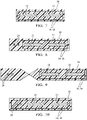
Fig. 7 is a cross section of a shielded electrical conductor with the conductive layer in an alternative configuration toFig. 2 according to some embodiments; -
Fig. 8 is a cross section of a shielded electrical conductor including additional signal conductors with the conductive layer in an alternative configuration toFig. 5 according to some embodiments; -
Fig. 9 is a cross section of a shielded electrical conductor including additional signal conductors with the first insulative layer in an alternative configuration toFig. 8 according to some embodiments; -
Fig. 10 is a cross section of a shielded electrical conductor including additional signal conductors with the conductive layer in an alternative configuration toFig. 8 according to some embodiments; -
Fig. 11 is a perspective view of an alternative shielded electrical conductor assembly having a portion of the shielded electrical conductor that is formed to have a shape that has an undulating shape, a wavy shape, a rippled shape, a pleated shape and an accordion shape according to some embodiments; -
Fig. 12 is a partial perspective view of an apparatus configured to have a shape that has an undulating shape, a wavy shape, a rippled shape, a pleated shape and an accordion shape according to some embodiments; -
Fig. 13 is a transparent view of the apparatus ofFig. 12 according to some embodiments; -
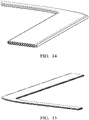
Fig. 14 a perspective view of an alternative shielded electrical conductor that is generally L-shaped according to some embodiments; -
Fig. 15 is an alternative perspective view of the shielded electrical conductor ofFig. 14 according to some embodiments; -
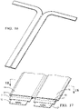
Fig. 16 a perspective view of an alternative shielded electrical conductor that is generally T-shaped according to some embodiments; -
Fig. 17 is a perspective view of another shielded electrical conductor assembly according to some embodiments; -
Fig. 18 is a cross-section view of the shielded electrical conductor assembly ofFig. 17 according to some embodiments; and -
Fig. 19 is a cross-section view of the shielded electrical conductor assembly ofFig. 17 according to some other embodiments. - A shielded electrical conductor assembly, hereinafter referred to as the
assembly 10 is presented herein. Non-limiting examples of theassembly 10 are shown inFigs. 1-10 . As shown inFig. 2 , theassembly 10 includes thin (stacked or adjacent) conductor(s), i.e.,conductor strips 12, that are formed from a copper or aluminum sheet and have a generally rectangular cross section. Theconductor strips 12 may be arranged in a single or a multiple/layered configuration. Theconductor strips 12 have a rectangular cross section which have has a larger surface area than round conductors having the same cross-sectional area. The larger surface area of theconductor strips 12 improves the heat dissipation rate from the assembly. This allows theconductor strips 12 to carry the same current as a round conductors with a larger cross-sectional area and still met a given maximum temperature-rise requirement. This provides a reduction in the conductive material, e.g., copper or aluminum, required to form therectangular conductor strips 12, thereby reducing material costs. - The number of
conductor strips 12 in the assembly is dependent on electrical design requirements, e.g., current, voltage, electrical resistance per unit length, desired heat dissipation rate, etc. The thickness of theconductor strips 12 is generally, but not limited, the range of 0.200 mm to 0.400 mm thick. The width of the conductor strips 12 is generally, but not limited to the range of 10 mm to 30 mm. - As illustrated in
Fig. 2 , the individual conductor strips are insulated by afirst layer 14 of dielectric laminate that are made of a thin thermoplastic (PEN, PET, etc.) film surrounding the conductor strips to electrically insulate the conductor strips while providing a low cost, highly efficient heat transfer medium. - As also shown in
Fig. 2 , ashield conductor 16 is added to the assembly to provide electromagnetic shielding. Theshield conductor 16 may be a conductive layer of a thin aluminized polyester film, e.g., MYLAR film, surrounding thefirst insulative layer 14.Multiple shield conductors 16 may individually surround eachconductor strip 12 as shown inFig. 3 or asingle shield conductor 16 may surround multiple conductor strips 12 as shown inFig. 7 . - The
shield conductors 16 are insulated by asecond layer 18 of dielectric laminate that is made of a thin thermoplastic film (PEN, PET, etc.) surrounding theshield conductors 16 to electrically insulate theshield conductors 16 while providing a low cost, highly efficient heat transfer medium. - The modular configuration of the
assembly 10 allows for aconnector 20 terminating the shielded electrical conductor assembly to have multiple terminations for thesame conductor strip 12, thereby enabling a multi-terminal termination of theconductor strip 12. - In an application electrically connecting a heat pump or other auxiliary type connections, this can result in a 2- or 4-way terminal connector, potentially more in some applications. As shown in
Figs. 3 and4 , the conductor strips 12 may be arranged in a side-by-side configuration and then folded one on top of the other to reduce the overall width of theassembly 10. A section of thefirst layer 14 of dielectric laminates may have a reduced thickness to facilitate folding the assembly. Adding asecond conductor strip 12 can increase the current carrying ability of theassembly 10 by 80% or more, by either adding to the amount of conductor material to carry more current through conductor strips 12 in series or packaging more conductor strips 12 to be ran in parallel. Running the separate conductor strips 12 in parallel would allow for wider conductor(s) in eachconductor strip 12 for a given packaging width. - The
conductor strip 12 shape is dependent on specific design requirements but can be fashioned in a manner that allows the formation of an integral terminal, e.g., a male blade terminal. Other component terminal fixations are possible for both the conductor(s) and shield(s) as required. - The terminals are collated, indexed, and secured into the
plastic connectors 20 as shown inFig. 1 , to facilitate electrical connection and vehicle assembly. Depending on design requirements, theassembly 10 can contain bothpower circuits 22 andsignal circuits 24 as shown inFigs. 5-6 and 8-10. Thesesignal circuits 24 may have a smaller cross section that thepower circuits 22 and can be shielded or unshielded and may be arranged in multiple configurations. - Additional
plastic components 26 illustrated inFig. 1 may be added to the assembly for cable routing and attachment to the vehicle. - Undulating, wavy, rippled, pleated, or accordion shaped features 28, as shown in
Fig. 11 can be formed into theassembly 10 to provide vibration dampening and allow for thermal expansion and/or extension of theassembly 10 needed to make electrical connections.Figs. 12 and13 illustrate tools that are configured to for these Undulating, wavy, rippled, pleated, or accordion shaped features 28. - In addition to the straight configuration of the assembly shown in
Figs. 1-12 , the assembly may be formed in a L-shape as shown inFigs. 14 and 15 or a T-shape as shown inFig. 16 . Alternatively, the assembly may be strategically slit to provide some degree of bending/twisting flexibility in the assembly. -
Figs. 17 to 19 illustrate yet another example of theassembly 10 having conductor strips 12 that are insulated by afirst layer 14 of dielectric laminate. As shown inFig. 18 , theassembly 10 includes twoseparate shield conductors 16 outside thefirst layer 14 of dielectric laminate that overlap the conductor strips 12 and two moreseparate shield conductors 16 that flank the conductor strips 12. Theshield conductors 16 are all tied to a common ground potential. As shown inFig. 18 , theassembly 10 includes twoseparate shield conductors 16 that overlap the conductor strips 12 but the flanking shield conductors are eliminated. The overlappingshield conductors 16 may extend past the conductor strips 12 by about 10% of the width of the conductor strips 12. Theshield conductors 16 are insulated by asecond layer 18 of dielectric laminate film surrounding theshield conductors 16. - The
assembly 10 has a lighter weight compared to equivalent traditional round conducot4r wiring assemblies. The lighter weight of theassembly 10 also provides material cost savings. Theassembly 10 is also simple to manufacture and so expensive tooling is not needed. In addition, vehicle installation is markedly simplified due to the assembly's lighter weight and flexibility. - While the embodiments of the
assembly 10 described herein are directed for use in an electric vehicle, other embodiments may be envisioned for use in other purposes, such as industrial machines, building wiring, and many other high current/high voltage applications. - While this invention has been described in terms of the preferred embodiments thereof, it is not intended to be so limited, but rather only to the extent set forth in the claims that follow. For example, the above-described embodiments (and/or aspects thereof) may be used in combination with each other. In addition, many modifications may be made to configure a situation or material to the teachings of the invention without departing from its scope. Dimensions, types of materials, orientations of the various components, and the number and positions of the various components described herein are intended to define parameters of certain embodiments and are by no means limiting and are merely prototypical embodiments.
- Many other embodiments and modifications within the spirit and scope of the claims will be apparent to those of skill in the art upon reviewing the above description. The scope of the invention should, therefore, be determined with reference to the following claims, along with the full scope of equivalents to which such claims are entitled.
- As used herein, 'one or more' includes a function being performed by one element, a function being performed by more than one element, e.g., in a distributed fashion, several functions being performed by one element, several functions being performed by several elements, or any combination of the above.
- It will also be understood that, although the terms first, second, etc. are, in some instances, used herein to describe various elements, these elements should not be limited by these terms. These terms are only used to distinguish one element from another. For example, a first contact could be termed a second contact, and, similarly, a second contact could be termed a first contact, without departing from the scope of the various described embodiments. The first contact and the second contact are both contacts, but they are not the same contact.
- The terminology used in the description of the various described embodiments herein is for the purpose of describing embodiments only and is not intended to be limiting. As used in the description of the various described embodiments and the appended claims, the singular forms "a", "an" and "the" are intended to include the plural forms as well, unless the context clearly indicates otherwise. It will also be understood that the term "and/or" as used herein refers to and encompasses all possible combinations of one or more of the associated listed items. It will be further understood that the terms "includes," "including," "comprises," and/or "comprising," when used in this specification, specify the presence of stated features, integers, steps, operations, elements, and/or components, but do not preclude the presence or addition of one or more other features, integers, steps, operations, elements, components, and/or groups thereof.
- As used herein, the term "if' is, optionally, construed to mean "when" or "upon" or "in response to determining" or "in response to detecting," depending on the context. Similarly, the phrase "if it is determined" or "if [a stated condition or event] is detected" is, optionally, construed to mean "upon determining" or "in response to determining" or "upon detecting [the stated condition or event]" or "in response to detecting [the stated condition or event]," depending on the context.
- Additionally, while terms of ordinance or orientation may be used herein these elements should not be limited by these terms. All terms of ordinance or orientation, unless stated otherwise, are used for purposes distinguishing one element from another, and do not denote any order of operations, direction or orientation unless stated otherwise.
Claims (15)
- A shielded electrical conductor assembly (10), comprising:an electrical conductor (12) having a rectangular cross-section;a first insulative layer (14) surrounding the electrical conductor (12);a conductive layer (16) surrounding the first insulative layer (14); anda second insulative layer (18) encasing the conductive layer (16).
- The shielded electrical conductor assembly (10) according to claim 1, wherein a cross-sectional area of the electrical conductor (12) is in a range of 2 to 12 square millimeters.
- The shielded electrical conductor assembly (10) according to claim 1 or 2, wherein a cross-sectional ratio of width to height of the electrical conductor (12) is in a range of 50:1 to 75:1.
- The shielded electrical conductor assembly (10) according to any one of the preceding claims, wherein a material forming the electrical conductor (12) is selected from a list consisting of a copper-based material and an aluminum-based material.
- The shielded electrical conductor assembly (10) according to any one of the preceding claims, wherein materials forming the first insulative layer (14) and the second insulative layer (18) are selected from a list consisting of a polyethylene terephthalate material and a polyethylene naphthalate material.
- The shielded electrical conductor assembly (10) according to any one of the preceding claims, wherein the shielded electrical conductor assembly (10) comprises a pair of the electrical conductors (12).
- The shielded electrical conductor assembly (10) according to claim 6, wherein a first electrical conductor (12) in the pair of the electrical conductors (12) is stacked on top of a second electrical conductor (12) in the pair of electrical conductors (12).
- The shielded electrical conductor assembly (10) according to claim 6 or 7, wherein a thickness of the first insulative layer (14) in a region between the pair of electrical conductors (12) is reduced in comparison to a thickness of a remaining portion of the first insulative layer (14).
- The shielded electrical conductor assembly (10) according to any one of claims 6 to 8, wherein the conductive layer (16) surrounds a first electrical conductor (12) in the pair of electrical conductors (12) and a second electrical conductor (12) in the pair of electrical conductors (12).
- The shielded electrical conductor assembly (10) according to any one of claims 6 to 9, wherein the conductive layer (16) surrounds a first electrical conductor (12) in the pair of electrical conductors (12) and wherein the shielded electrical conductor assembly (10) further comprises a third insulative layer surrounding a second electrical conductor (12) in the pair of electrical conductors (12).
- The shielded electrical conductor assembly (10) according to any one of claims 6 to 10, wherein the pair of electrical conductors (12) is a first pair of electrical conductors (22) and wherein the shielded electrical conductor assembly (10) further comprises a second pair of electrical conductors (24) having a cross-sectional area at least 50% smaller than a cross-sectional area of the first pair of electrical conductors (12).
- The shielded electrical conductor assembly (10) according to claim 11, wherein the second pair of electrical conductors (24) is located outboard of one electrical conductor (22) in the first pair of electrical conductors (12).
- The shielded electrical conductor assembly (10) according to claim 11 or 12, wherein a first electrical conductor (24) of the second pair of electrical conductors (24) is located outboard of a first electrical conductor (22) in the first pair of electrical conductors (22) and a second electrical conductor (24) of the second pair of electrical conductors (24) is located outboard of a second electrical conductor (22) in the first pair of electrical conductors (22).
- The shielded electrical conductor assembly (10) according to any one of claims 11 to 13, wherein a thickness of the first insulative layer (14) in a region between the first pair of electrical conductors (22) and the second pair of electrical conductors (24) is reduced in comparison to a thickness of a remaining portion of the first insulative layer (14).
- The shielded electrical conductor assembly (10) according to any one of the preceding claims, wherein a portion of the shielded electrical conductor assembly (10) is formed to have a shape selected from a list consisting of an undulating shape, a wavy shape, a rippled shape, a pleated shape, an accordion shape, a straight shape, an L-shape, and a T-shape.
Applications Claiming Priority (2)
| Application Number | Priority Date | Filing Date | Title |
|---|---|---|---|
| US202163212255P | 2021-06-18 | 2021-06-18 | |
| US17/837,346 US20220406490A1 (en) | 2021-06-18 | 2022-06-10 | Shielded flat electrical conductor assembly |
Publications (1)
| Publication Number | Publication Date |
|---|---|
| EP4105947A1 true EP4105947A1 (en) | 2022-12-21 |
Family
ID=82058431
Family Applications (1)
| Application Number | Title | Priority Date | Filing Date |
|---|---|---|---|
| EP22178973.8A Pending EP4105947A1 (en) | 2021-06-18 | 2022-06-14 | Shielded flat electrical conductor assembly |
Country Status (3)
| Country | Link |
|---|---|
| US (1) | US20220406490A1 (en) |
| EP (1) | EP4105947A1 (en) |
| CN (1) | CN115497668A (en) |
Cited By (1)
| Publication number | Priority date | Publication date | Assignee | Title |
|---|---|---|---|---|
| EP4390979A1 (en) * | 2022-12-22 | 2024-06-26 | Aptiv Technologies AG | Flexible flat wire cable with high frequency conductors |
Citations (5)
| Publication number | Priority date | Publication date | Assignee | Title |
|---|---|---|---|---|
| US3576723A (en) * | 1968-04-23 | 1971-04-27 | Nasa | Method of making shielded flat cable |
| GB1529280A (en) * | 1976-05-18 | 1978-10-18 | Bosch Siemens Hausgeraete | Tape cable |
| JPH11120831A (en) * | 1997-10-14 | 1999-04-30 | Tatsuta Electric Wire & Cable Co Ltd | Shielded flat cable |
| US20150034381A1 (en) * | 2013-07-30 | 2015-02-05 | Andrew Llc | Hybrid cable with flat power conductors |
| US20180345886A1 (en) * | 2015-11-04 | 2018-12-06 | Auto-Kabel Management Gmbh | Multi-Voltage On-Board Electrical System and Multilayer Cable for Different Voltage Levels |
Family Cites Families (16)
| Publication number | Priority date | Publication date | Assignee | Title |
|---|---|---|---|---|
| US3391246A (en) * | 1964-03-16 | 1968-07-02 | Westinghouse Electric Corp | Multiconductor flat cables |
| US3582532A (en) * | 1969-11-26 | 1971-06-01 | Walter A Plummer | Shielded jacket assembly for flat cables |
| US3612743A (en) * | 1970-10-13 | 1971-10-12 | Nasa | Shielded flat cable |
| US3757029A (en) * | 1972-08-14 | 1973-09-04 | Thomas & Betts Corp | Shielded flat cable |
| US4287385A (en) * | 1979-09-12 | 1981-09-01 | Carlisle Corporation | Shielded flat cable |
| US4475006A (en) * | 1981-03-16 | 1984-10-02 | Minnesota Mining And Manufacturing Company | Shielded ribbon cable |
| JPH0614326Y2 (en) * | 1988-10-24 | 1994-04-13 | 住友電気工業株式会社 | Flat cable with shield |
| US5025115A (en) * | 1990-05-22 | 1991-06-18 | W. L. Gore & Associates, Inc. | Insulated power cables |
| US5342991A (en) * | 1993-03-03 | 1994-08-30 | The Whitaker Corporation | Flexible hybrid branch cable |
| US5428187A (en) * | 1994-02-24 | 1995-06-27 | Molex Incorporated | Shielded hybrid ribbon cable assembly |
| US6403887B1 (en) * | 1997-12-16 | 2002-06-11 | Tensolite Company | High speed data transmission cable and method of forming same |
| JP2011204503A (en) * | 2010-03-26 | 2011-10-13 | Hitachi Cable Fine Tech Ltd | Flexible flat cable |
| JP5621789B2 (en) * | 2012-01-05 | 2014-11-12 | 住友電気工業株式会社 | Shielded flat cable |
| US10269258B2 (en) * | 2013-05-16 | 2019-04-23 | The Regents Of The University Of California | System for automatic assessment of student learning |
| JP6650369B2 (en) * | 2016-07-28 | 2020-02-19 | 株式会社Jvcケンウッド | Electronics |
| CN107799225B (en) * | 2016-08-29 | 2019-08-13 | 贝尔威勒电子股份有限公司 | High-frequency transmission cable |
-
2022
- 2022-06-10 US US17/837,346 patent/US20220406490A1/en not_active Abandoned
- 2022-06-14 EP EP22178973.8A patent/EP4105947A1/en active Pending
- 2022-06-16 CN CN202210679969.0A patent/CN115497668A/en active Pending
Patent Citations (5)
| Publication number | Priority date | Publication date | Assignee | Title |
|---|---|---|---|---|
| US3576723A (en) * | 1968-04-23 | 1971-04-27 | Nasa | Method of making shielded flat cable |
| GB1529280A (en) * | 1976-05-18 | 1978-10-18 | Bosch Siemens Hausgeraete | Tape cable |
| JPH11120831A (en) * | 1997-10-14 | 1999-04-30 | Tatsuta Electric Wire & Cable Co Ltd | Shielded flat cable |
| US20150034381A1 (en) * | 2013-07-30 | 2015-02-05 | Andrew Llc | Hybrid cable with flat power conductors |
| US20180345886A1 (en) * | 2015-11-04 | 2018-12-06 | Auto-Kabel Management Gmbh | Multi-Voltage On-Board Electrical System and Multilayer Cable for Different Voltage Levels |
Cited By (1)
| Publication number | Priority date | Publication date | Assignee | Title |
|---|---|---|---|---|
| EP4390979A1 (en) * | 2022-12-22 | 2024-06-26 | Aptiv Technologies AG | Flexible flat wire cable with high frequency conductors |
Also Published As
| Publication number | Publication date |
|---|---|
| CN115497668A (en) | 2022-12-20 |
| US20220406490A1 (en) | 2022-12-22 |
Similar Documents
| Publication | Publication Date | Title |
|---|---|---|
| US9870845B2 (en) | Multi-layer coaxial cable | |
| EP2584664B1 (en) | Integrated-type shield protector and wire harness | |
| JP5491224B2 (en) | Wire harness | |
| CN102884691B (en) | Wire harness | |
| US9346420B2 (en) | Wire harness | |
| EP2841309B1 (en) | Wire harness | |
| EP3043358B1 (en) | Metal sheathed cable with jacketed, cabled conductor subassembly | |
| EP2782790B1 (en) | High voltage conductive wire and wire harness | |
| US20140284100A1 (en) | Wire harness | |
| US20220406490A1 (en) | Shielded flat electrical conductor assembly | |
| CN109285633B (en) | Method for producing a busbar by means of a metal core and busbar | |
| EP2738775A1 (en) | High-voltage conduction path and wiring harness | |
| EP2741386A1 (en) | Wire harness | |
| US20180301246A1 (en) | Wiring member and method of manufacturing wiring member | |
| US20140034383A1 (en) | Wire harness | |
| CN119032478A (en) | Multi-core rigid busbar for power distribution | |
| US20160137146A1 (en) | Shielded wire and wire harness | |
| US20240412895A1 (en) | Shielded electrical conductor with folded shielding layer | |
| CN115332848A (en) | Contact devices, joints and contact systems for double busbars | |
| JP2011150849A (en) | Shielded cable | |
| JP5621716B2 (en) | Wire harness | |
| JP2020077498A (en) | Cabling | |
| US11791597B2 (en) | Flexible electrical bus bar and method of manufacturing the same | |
| US12633710B2 (en) | Flexible electrical bus bar and method of manufacturing the same | |
| EP4225000A1 (en) | Flexible electrical bus bar and method of manufacturing the same |
Legal Events
| Date | Code | Title | Description |
|---|---|---|---|
| PUAI | Public reference made under article 153(3) epc to a published international application that has entered the european phase |
Free format text: ORIGINAL CODE: 0009012 |
|
| STAA | Information on the status of an ep patent application or granted ep patent |
Free format text: STATUS: THE APPLICATION HAS BEEN PUBLISHED |
|
| AK | Designated contracting states |
Kind code of ref document: A1 Designated state(s): AL AT BE BG CH CY CZ DE DK EE ES FI FR GB GR HR HU IE IS IT LI LT LU LV MC MK MT NL NO PL PT RO RS SE SI SK SM TR |
|
| STAA | Information on the status of an ep patent application or granted ep patent |
Free format text: STATUS: REQUEST FOR EXAMINATION WAS MADE |
|
| 17P | Request for examination filed |
Effective date: 20230214 |
|
| RBV | Designated contracting states (corrected) |
Designated state(s): AL AT BE BG CH CY CZ DE DK EE ES FI FR GB GR HR HU IE IS IT LI LT LU LV MC MK MT NL NO PL PT RO RS SE SI SK SM TR |
|
| RAP3 | Party data changed (applicant data changed or rights of an application transferred) |
Owner name: APTIV TECHNOLOGIES LIMITED |
|
| RAP1 | Party data changed (applicant data changed or rights of an application transferred) |
Owner name: APTIV TECHNOLOGIES AG |
|
| STAA | Information on the status of an ep patent application or granted ep patent |
Free format text: STATUS: EXAMINATION IS IN PROGRESS |
|
| 17Q | First examination report despatched |
Effective date: 20240801 |
|
| RAP3 | Party data changed (applicant data changed or rights of an application transferred) |
Owner name: APTIV TECHNOLOGIES AG |