EP4105919A1 - Light field near-eye display and method thereof for generating virtual reality images - Google Patents
Light field near-eye display and method thereof for generating virtual reality images Download PDFInfo
- Publication number
- EP4105919A1 EP4105919A1 EP21203598.4A EP21203598A EP4105919A1 EP 4105919 A1 EP4105919 A1 EP 4105919A1 EP 21203598 A EP21203598 A EP 21203598A EP 4105919 A1 EP4105919 A1 EP 4105919A1
- Authority
- EP
- European Patent Office
- Prior art keywords
- image
- display
- eye
- virtual reality
- sub
- Prior art date
- Legal status (The legal status is an assumption and is not a legal conclusion. Google has not performed a legal analysis and makes no representation as to the accuracy of the status listed.)
- Withdrawn
Links
Images


Classifications
-
- G—PHYSICS
- G02—OPTICS
- G02B—OPTICAL ELEMENTS, SYSTEMS OR APPARATUS
- G02B27/00—Optical systems or apparatus not provided for by any of the groups G02B1/00 - G02B26/00, G02B30/00
- G02B27/01—Head-up displays
- G02B27/0179—Display position adjusting means not related to the information to be displayed
-
- G—PHYSICS
- G09—EDUCATION; CRYPTOGRAPHY; DISPLAY; ADVERTISING; SEALS
- G09G—ARRANGEMENTS OR CIRCUITS FOR CONTROL OF INDICATING DEVICES USING STATIC MEANS TO PRESENT VARIABLE INFORMATION
- G09G3/00—Control arrangements or circuits, of interest only in connection with visual indicators other than cathode-ray tubes
- G09G3/001—Control arrangements or circuits, of interest only in connection with visual indicators other than cathode-ray tubes using specific devices not provided for in groups G09G3/02 - G09G3/36, e.g. using an intermediate record carrier such as a film slide; Projection systems; Display of non-alphanumerical information, solely or in combination with alphanumerical information, e.g. digital display on projected diapositive as background
-
- G—PHYSICS
- G02—OPTICS
- G02B—OPTICAL ELEMENTS, SYSTEMS OR APPARATUS
- G02B27/00—Optical systems or apparatus not provided for by any of the groups G02B1/00 - G02B26/00, G02B30/00
- G02B27/0093—Optical systems or apparatus not provided for by any of the groups G02B1/00 - G02B26/00, G02B30/00 with means for monitoring data relating to the user, e.g. head-tracking, eye-tracking
-
- G—PHYSICS
- G02—OPTICS
- G02B—OPTICAL ELEMENTS, SYSTEMS OR APPARATUS
- G02B27/00—Optical systems or apparatus not provided for by any of the groups G02B1/00 - G02B26/00, G02B30/00
- G02B27/01—Head-up displays
- G02B27/017—Head mounted
- G02B27/0172—Head mounted characterised by optical features
-
- G—PHYSICS
- G06—COMPUTING OR CALCULATING; COUNTING
- G06F—ELECTRIC DIGITAL DATA PROCESSING
- G06F3/00—Input arrangements for transferring data to be processed into a form capable of being handled by the computer; Output arrangements for transferring data from processing unit to output unit, e.g. interface arrangements
- G06F3/01—Input arrangements or combined input and output arrangements for interaction between user and computer
- G06F3/011—Arrangements for interaction with the human body, e.g. for user immersion in virtual reality
- G06F3/013—Eye tracking input arrangements
-
- G—PHYSICS
- G02—OPTICS
- G02B—OPTICAL ELEMENTS, SYSTEMS OR APPARATUS
- G02B27/00—Optical systems or apparatus not provided for by any of the groups G02B1/00 - G02B26/00, G02B30/00
- G02B27/01—Head-up displays
- G02B27/0179—Display position adjusting means not related to the information to be displayed
- G02B2027/0187—Display position adjusting means not related to the information to be displayed slaved to motion of at least a part of the body of the user, e.g. head, eye
-
- G—PHYSICS
- G09—EDUCATION; CRYPTOGRAPHY; DISPLAY; ADVERTISING; SEALS
- G09G—ARRANGEMENTS OR CIRCUITS FOR CONTROL OF INDICATING DEVICES USING STATIC MEANS TO PRESENT VARIABLE INFORMATION
- G09G2320/00—Control of display operating conditions
- G09G2320/02—Improving the quality of display appearance
- G09G2320/0233—Improving the luminance or brightness uniformity across the screen
-
- G—PHYSICS
- G09—EDUCATION; CRYPTOGRAPHY; DISPLAY; ADVERTISING; SEALS
- G09G—ARRANGEMENTS OR CIRCUITS FOR CONTROL OF INDICATING DEVICES USING STATIC MEANS TO PRESENT VARIABLE INFORMATION
- G09G2360/00—Aspects of the architecture of display systems
- G09G2360/16—Calculation or use of calculated indices related to luminance levels in display data
Definitions
- the invention relates to a light field near-eye display technology, and more particularly to a light field near-eye display and a method thereof for generating virtual reality images.
- the light field near-eye display is currently one of the display technologies that can solve the vergence accommodation conflict.
- the light field near-eye display using a micro-lens array with a plurality of sub-lenses can combine a plurality of sub-images generated by the sub-lenses into a spatially three-dimensional virtual image.
- an eye box size is defined as a certain range within which the eyeball can move and view the complete image. This range is limited by the area where the beams of the sub-lens converge or intersect.
- the invention provides a light field near-eye display and its method for generating virtual reality images that can improve the uniformity of image brightness and expand the eye box size.
- the light field near-eye display for generating virtual reality images includes a light field display module and an eye tracking module.
- the light field display module is configured to calculate a compensation mask according to a simulated image and superimpose the compensation mask on a target image to generate a superimposed target image, wherein brightness distributions of the simulated image and the compensation mask are opposite to each other.
- the eye tracking module is configured to provide a plurality of eye movement parameters, and the light field display module is further configured to shift a display image according to a change vector of the plurality of eye movement parameters, wherein the display image is converted from the superimposed target image.
- the method for generating virtual reality images and used in a light field near-eye display includes steps of: calculating a compensation mask according to a simulated image and superimposing the compensation mask on a target image to generate a superimposed target image, wherein brightness distributions of the simulated image and the compensation mask are opposite to each other; and shifting a display image according to a change vector of a plurality of eye movement parameters, wherein the display image is converted from the superimposed target image.
- the plurality of eye movement parameters may comprise a distance between an eyeball position and a predetermined position, a distance between a pupil position and the predetermined position, or a size of a pupil.
- the step of calculating the compensation mask according to the simulated image may comprise steps of generating the simulated image through a light field near-eye display simulation with a white field image; and generating the compensation mask according to a brightness value difference between each pixel of the white field image and a corresponding pixel of the simulated image.
- the white field image may be a grayscale image, a checkerboard image, or a line image.
- the step of superimposing the compensation mask on the target image may comprise a step of multiplying a brightness value of each pixel of the target image by a value of a corresponding pixel of the compensation mask.
- the step of shifting the display image according to the change vector of the plurality of eye movement parameters may comprise steps of establishing a spatial movement range of a plurality of sub-display images included in the display image according to the eyeball position; and tracking a change vector of the pupil position to shift positions of the plurality of sub-display images within the spatial movement range of each of the plurality of sub-display images.
- shifting the position of each of the plurality of sub-display images within the spatial movement range may be calculating a displacement vector of each of the plurality of sub-display images by interpolation calculation between spatial coordinates corresponding to a center and a boundary of the spatial movement range of each of the plurality of sub-display images.
- a displacement direction of each of the plurality of sub-display images and a deviation direction of the eyeball position may be opposite to each other.
- the distance between the eyeball position and the predetermined position may be between 0 mm and 6 mm.
- the light field near-eye display and its method for generating virtual reality images according to the invention superimpose a compensation mask for compensating brightness on the target image to compensate for the uneven brightness of the target image, and dynamically shift the display image corresponding to the target image according to the eye movement parameters.
- the uniformity of the brightness of the image can be improved and the eye box size can be enlarged.
- FIG. 1 is a schematic view of a light field near-eye display according to an embodiment of the invention.
- the light field near-eye display 1 of the embodiment includes a light field display module 2 and an eye tracking module 3.
- the eye tracking module 3 is connected to the light field display module 2.
- the light field display module 2 has a plurality of sub-lenses 21 and a display panel 22.
- the sub-lenses 21 are, for example, a micro-lens array.
- the display panel 22 is configured to display a display image.
- the display image includes a plurality of sub-display images.
- the eyeball 4 can view a virtual reality image formed by superimposing the sub-display images through the sub-lenses 21.
- the eye tracking module 3 is configured to track (monitor) a plurality of eye movement parameters.
- the eye movement parameters include a distance between an eyeball position and a predetermined position, a distance between a pupil position and the predetermined position, or a size of a pupil 41, wherein the predetermined position is, for example, in the center of the display panel 22.
- the position and quantity of the eye tracking module 3 in the light field near-eye display 1 in FIG. 1 are only examples, and those skilled in the art can select the position where the eye tracking module 3 is placed in the light field near-eye display 1 and the quantity of the eye tracking module 3 according to the actual needs, and the invention is not limited to this.
- the light field display module 2 can be configured to convert a target image into the sub-display images to be displayed on the display panel 22 (that is, the display image is converted from the target image), thus, the virtual reality image received by the eyeball 4 is similar to the target image.
- FIG. 2 is a flowchart of a method for generating virtual reality images according to an embodiment of the invention. Please refer to FIGS. 1 and 2 together.
- the light field near-eye display 1 of the embodiment of the invention is configured to perform a method for generating virtual reality images.
- the light field display module 2 is configured to calculate a compensation mask according to a simulated image and superimpose the compensation mask on the target image to generate a superimposed target image, wherein the brightness distributions of the simulated image and the compensation mask are opposite to each other.
- the eye tracking module 3 is configured to provide the eye movement parameters, and the light field display module 3 is further configured to shift the display image according to a change vector of the eye movement parameters, wherein the display image is converted from the superimposed target image.
- the method for generating virtual reality images takes the light field display module 2 executing the operation as an example, but the invention is not limited to this. In other implementations, all or part of the steps may be executed by the eye tracking module 3 or other processors or may also be executed by other light field near-eye displays, and the invention is not limited to this.
- the method for generating virtual reality images of this embodiment includes a step S1: calculating a compensation mask (image) according to a simulated image and superimposing the compensation mask on a target image to generate a superimposed target image, wherein brightness distributions of the simulated image and the compensation mask are opposite to each other; and a step S3: shifting a display image according to a change vector of a plurality of eye movement parameters, wherein the display image is converted from the superimposed target image.
- the steps S1 and S3 can be interchanged without priority (i.e., shifting the display image converted from the target image, and superimposing the compensation mask on the display image), and the invention is not limited to this.
- the step S1 includes a sub-step S11: generating the simulated image through a light field near-eye display simulation with a white field image, wherein the white field image is a grayscale image (single grayscale or multi grayscale image), a checkerboard image, or a line image; a sub-step S13: generating the compensation mask according to a brightness value difference between each pixel of the white field image and a corresponding pixel of the simulated image; and a sub-step S15: multiplying a brightness value of each pixel of the target image by a value of a corresponding pixel of the compensation mask.
- the target image after brightness compensation can be generated (i.e., generating a superimposed target image), so that the image viewed by the human eye has higher image brightness uniformity.
- the eyeball 4 can view the virtual reality image formed by superimposing the virtual sub-images of the white image through the sub-lenses 21.
- the brightness distribution of the virtual reality image may cause the brightness distribution (different brightness values) to produce a grid-like image due to the superimpose spacing, proportion and shape between the virtual sub-images. Therefore, the virtual reality image may have the problem of uneven brightness, that is, the general light field display module cannot present a virtual reality image with uniform brightness like the original white image.
- the light field display module 2 in this embodiment compares the brightness value of each pixel of the white field image with the brightness value of the corresponding pixel in the simulated image to obtain the brightness value difference of each pixel, thereby generating a compensation mask with the brightness value difference. Finally, the compensation mask is superimposed on the target image to be displayed by the light field display module 2, so that the brightness value of each pixel in the target image is superimposed by the brightness value difference of the corresponding pixel in the compensation mask. In this way, the virtual reality image viewed by the user is a white picture image with uniform brightness.
- the brightness normalization can be further performed after the brightness value of each pixel in the target image is superimposed by the brightness value difference of the corresponding pixel in the compensation mask, so as to scale the distribution of the brightness value between 0 and 1 or between -1 and 1 to simplify calculations.
- FIG. 4 is a flow chart of shifting a display image according to a change vector of a plurality of eye movement parameters according to an embodiment of the invention.
- FIG. 5 is a schematic view of expanding the eye box size according to an embodiment of the invention. Please refer to FIGS. 1, 4 and 5 together.
- the step S3 includes a sub-step S31: establishing a spatial movement range of a plurality of sub-display images included in the display image according to the eyeball position; and a sub-step S33: tracking a change vector of the pupil position to shift the position of each sub-display image within the spatial movement range of each sub-display image. In this way, the display image can be shifted.
- the light field display module 2 establishes the spatial movement range (dashed circle) of each sub-display image (solid circle) according to the eyeball position provided by the eye tracking module 3, so that the light field display module 2 can calculate the displacement vector (such as displacement distance and displacement direction) of each sub-display image by an interpolation calculation method between the spatial coordinates corresponding to the center and the boundary of the spatial movement range according to the movement distance and movement direction of the pupil 41 relative to the predetermined position provided by the eye tracking module 3, so that each sub-display image moves within its spatial movement range (that is, the position of the spatial movement range is fixed, for example), wherein the predetermined position of each sub-display image is located in the center of the spatial movement range, and the displacement direction and displacement distance of each sub-display image are approximately the same as each other.
- the displacement vector such as displacement distance and displacement direction
- the eye box size can be expanded by the method provided by the invention, wherein the eye box size can be expanded by more than 6mm on the left and right sides.
- the distance between the eyeball position and the predetermined position can be between 0mm and 6mm, and a complete virtual reality image can be seen on the left and right sides.
- FIG. 6A is a schematic view of an operation of an eye box size according to an embodiment of the invention.
- FIG. 6B is a schematic view of an operation of an eye box size according to another embodiment of the invention.
- the displacement direction and displacement distance of each sub-display image are opposite to the deviation direction of the eyeball position when the eyeball position deviates from the predetermined position.
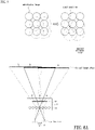
- the sub-display images A, B and C present the respective virtual sub-images a, b and c through the sub-lenses 21, and these virtual sub-images a, b and c are partially interlaced with each other to form a superimposed image.
- the eye tracking module 3 corrects the sub-display images A, B and C to shift to the left, and the deviated positions of the sub-display images A, B, and C are the coverage areas of the light projected by the deviated eye box size to form deviated sub-display images A', B' and C'.
- the virtual sub-images a', b' and c' are presented through the sub-lenses 21 to achieve the purpose of expanding the eye box size. It should be noted that the eye tracking module 3 can track the deviation and rotation of the eyeball position in any direction, and the invention is not limited to the above examples.
- the light field near-eye display and its method for generating virtual reality images according to the invention superimpose a compensation mask for compensating brightness on the target image to compensate for the uneven brightness of the target image, and dynamically shift the display image corresponding to the target image according to the eye movement parameters.
- a compensation mask for compensating brightness on the target image to compensate for the uneven brightness of the target image
- dynamically shift the display image corresponding to the target image according to the eye movement parameters the uniformity of the brightness of the image can be improved and the eye box size can be enlarged.
Landscapes
- Physics & Mathematics (AREA)
- General Physics & Mathematics (AREA)
- Engineering & Computer Science (AREA)
- Optics & Photonics (AREA)
- Theoretical Computer Science (AREA)
- General Engineering & Computer Science (AREA)
- Human Computer Interaction (AREA)
- Computer Hardware Design (AREA)
- Processing Or Creating Images (AREA)
- Testing, Inspecting, Measuring Of Stereoscopic Televisions And Televisions (AREA)
- Controls And Circuits For Display Device (AREA)
Abstract
Description
- This application claims priority of
China application (202110672253.3), filed on 06/17/2021 - The invention relates to a light field near-eye display technology, and more particularly to a light field near-eye display and a method thereof for generating virtual reality images.
- The light field near-eye display (LFNED) is currently one of the display technologies that can solve the vergence accommodation conflict. The light field near-eye display using a micro-lens array with a plurality of sub-lenses can combine a plurality of sub-images generated by the sub-lenses into a spatially three-dimensional virtual image. When the sub-images are overlapped and coveraged, the brightness of the virtual image will have an uneven brightness distribution due to the overlap and coverage of the sub-images. In addition, an eye box size is defined as a certain range within which the eyeball can move and view the complete image. This range is limited by the area where the beams of the sub-lens converge or intersect. When the eyeball deviates from the eye box size, the user may view a "broken image" due to the eyeball deviates from the area where the light beams converge or intersect. Therefore, there is a need for a light field near-eye display technology that can improve the uniformity of image brightness and expand the eye box size.
- The information disclosed in this "BACKGROUND OF THE INVENTION" section is only for enhancement understanding of the background of the invention and therefore it may contain information that does not form the prior art that is already known to a person of ordinary skill in the art. Furthermore, the information disclosed in this "BACKGROUND OF THE INVENTION" section does not mean that one or more problems to be solved by one or more embodiments of the invention were acknowledged by a person of ordinary skill in the art.
- The invention provides a light field near-eye display and its method for generating virtual reality images that can improve the uniformity of image brightness and expand the eye box size.
- Other advantages and objects of the invention may be further illustrated by the technical features broadly embodied and described as follows.
- The object is solved by the features of the independent claims. Preferred embodiments are given in the dependent claims.
- In order to achieve one or part or all of the above-mentioned purposes or other purposes, the light field near-eye display for generating virtual reality images provided by the invention includes a light field display module and an eye tracking module. The light field display module is configured to calculate a compensation mask according to a simulated image and superimpose the compensation mask on a target image to generate a superimposed target image, wherein brightness distributions of the simulated image and the compensation mask are opposite to each other. The eye tracking module is configured to provide a plurality of eye movement parameters, and the light field display module is further configured to shift a display image according to a change vector of the plurality of eye movement parameters, wherein the display image is converted from the superimposed target image.
- In order to achieve one or part or all of the above-mentioned purposes or other purposes, the method for generating virtual reality images and used in a light field near-eye display provided by the invention includes steps of: calculating a compensation mask according to a simulated image and superimposing the compensation mask on a target image to generate a superimposed target image, wherein brightness distributions of the simulated image and the compensation mask are opposite to each other; and shifting a display image according to a change vector of a plurality of eye movement parameters, wherein the display image is converted from the superimposed target image.
- The above mentioned aspects can be further equipped with one or more of the following optional features.
- In one or more embodiments, the plurality of eye movement parameters may comprise a distance between an eyeball position and a predetermined position, a distance between a pupil position and the predetermined position, or a size of a pupil.
- In one or more embodiments, the step of calculating the compensation mask according to the simulated image may comprise steps of generating the simulated image through a light field near-eye display simulation with a white field image; and generating the compensation mask according to a brightness value difference between each pixel of the white field image and a corresponding pixel of the simulated image.
- In one or more embodiments, the white field image may be a grayscale image, a checkerboard image, or a line image.
- In one or more embodiments, the step of superimposing the compensation mask on the target image may comprise a step of multiplying a brightness value of each pixel of the target image by a value of a corresponding pixel of the compensation mask.
- In one or more embodiments, the step of shifting the display image according to the change vector of the plurality of eye movement parameters may comprise steps of establishing a spatial movement range of a plurality of sub-display images included in the display image according to the eyeball position; and tracking a change vector of the pupil position to shift positions of the plurality of sub-display images within the spatial movement range of each of the plurality of sub-display images.
- In one or more embodiments, shifting the position of each of the plurality of sub-display images within the spatial movement range may be calculating a displacement vector of each of the plurality of sub-display images by interpolation calculation between spatial coordinates corresponding to a center and a boundary of the spatial movement range of each of the plurality of sub-display images.
- In one or more embodiments, when the eyeball position deviates from a predetermined position, a displacement direction of each of the plurality of sub-display images and a deviation direction of the eyeball position may be opposite to each other.
- In one or more embodiments, the distance between the eyeball position and the predetermined position may be between 0 mm and 6 mm.The light field near-eye display and its method for generating virtual reality images according to the invention superimpose a compensation mask for compensating brightness on the target image to compensate for the uneven brightness of the target image, and dynamically shift the display image corresponding to the target image according to the eye movement parameters. Thus, the uniformity of the brightness of the image can be improved and the eye box size can be enlarged.
- Other objectives, features and advantages of the invention will be further understood from the further technological features disclosed by the embodiments of the invention wherein there are shown and described preferred embodiments of this invention, simply by way of illustration of modes best suited to carry out the invention.
- The accompanying drawings are included to provide a further understanding of the invention. The drawings illustrate embodiments of the invention and, together with the description, serve to explain the principles of the invention.
-
FIG.1 is a schematic view of a light field near-eye display of an embodiment of the invention; -
FIG.2 flowchart of a method for generating virtual reality images of an embodiment; -
FIG. 3 is a flowchart of calculating a compensation mask according to a simulated image and superimposing the compensation mask to a target image of an embodiment of the invention; -
FIG. 4 is a flow chart of shifting a display image according to a change vector of a plurality of eye movement parameters according to an embodiment of the invention; -
FIG. 5 is a schematic view of expanding the eye box size of an embodiment of the invention; -
FIG.6A schematic view of an operation of an eye box size of an embodiment of the invention; -
FIG.6B schematic view of operation of an eye box size of another embodiment of the invention. - In the following detailed description of the preferred embodiments, reference is made to the accompanying drawings which form a part hereof, and in which is shown by way of illustration specific embodiments in which the invention may be practiced. In this regard, directional terminology, such as "top", "bottom", "front", "back", etc., is used with reference to the orientation of the Figure(s) being described. The components of the invention can be positioned in a number of different orientations. As such, the directional terminology is used for purposes of illustration and is in no way limiting. On the other hand, the drawings are only schematic and the sizes of components may be exaggerated for clarity. It is to be understood that other embodiments may be utilized and structural changes may be made without departing from the scope of the invention. Also, it is to be understood that the phraseology and terminology used herein are for the purpose of description and should not be regarded as limiting. The use of "including", "comprising", or "having" and variations thereof herein is meant to encompass the items listed thereafter and equivalents thereof as well as additional items. Unless limited otherwise, the terms "connected", "coupled", and "mounted" and variations thereof herein are used broadly and encompass direct and indirect connections, couplings, and mountings. Similarly, the terms "facing", "faces", and variations thereof herein are used broadly and encompass direct and indirect facing, and "adjacent to" and variations thereof herein are used broadly and encompass directly and indirectly "adjacent to". Therefore, the description of "A" component facing "B" component herein may contain the situations that "A" component facing "B" component directly or one or more additional components is between "A" component and "B" component. Also, the description of "A" component "adjacent to" "B" component herein may contain the situations that "A" component is directly "adjacent to" "B" component or one or more additional components is between "A" component and "B" component. Accordingly, the drawings and descriptions will be regarded as illustrative in nature and not as restrictive.
-
FIG. 1 is a schematic view of a light field near-eye display according to an embodiment of the invention. Please refer toFIG. 1 . The light field near-eye display 1 of the embodiment includes a lightfield display module 2 and aneye tracking module 3. Theeye tracking module 3 is connected to the lightfield display module 2. The lightfield display module 2 has a plurality ofsub-lenses 21 and adisplay panel 22. Thesub-lenses 21 are, for example, a micro-lens array. Thedisplay panel 22 is configured to display a display image. The display image includes a plurality of sub-display images. The eyeball 4 can view a virtual reality image formed by superimposing the sub-display images through the sub-lenses 21. Theeye tracking module 3 is configured to track (monitor) a plurality of eye movement parameters. The eye movement parameters include a distance between an eyeball position and a predetermined position, a distance between a pupil position and the predetermined position, or a size of apupil 41, wherein the predetermined position is, for example, in the center of thedisplay panel 22. It should be noted that the position and quantity of theeye tracking module 3 in the light field near-eye display 1 inFIG. 1 are only examples, and those skilled in the art can select the position where theeye tracking module 3 is placed in the light field near-eye display 1 and the quantity of theeye tracking module 3 according to the actual needs, and the invention is not limited to this. It should be noted that the lightfield display module 2 can be configured to convert a target image into the sub-display images to be displayed on the display panel 22 (that is, the display image is converted from the target image), thus, the virtual reality image received by the eyeball 4 is similar to the target image. -
FIG. 2 is a flowchart of a method for generating virtual reality images according to an embodiment of the invention. Please refer toFIGS. 1 and 2 together. In order to improve the image brightness uniformity and expand the eye box size, the light field near-eye display 1 of the embodiment of the invention is configured to perform a method for generating virtual reality images. The lightfield display module 2 is configured to calculate a compensation mask according to a simulated image and superimpose the compensation mask on the target image to generate a superimposed target image, wherein the brightness distributions of the simulated image and the compensation mask are opposite to each other. Theeye tracking module 3 is configured to provide the eye movement parameters, and the lightfield display module 3 is further configured to shift the display image according to a change vector of the eye movement parameters, wherein the display image is converted from the superimposed target image. It should be noted that the method for generating virtual reality images according to the embodiment of the invention takes the lightfield display module 2 executing the operation as an example, but the invention is not limited to this. In other implementations, all or part of the steps may be executed by theeye tracking module 3 or other processors or may also be executed by other light field near-eye displays, and the invention is not limited to this. In detail, the method for generating virtual reality images of this embodiment includes a step S1: calculating a compensation mask (image) according to a simulated image and superimposing the compensation mask on a target image to generate a superimposed target image, wherein brightness distributions of the simulated image and the compensation mask are opposite to each other; and a step S3: shifting a display image according to a change vector of a plurality of eye movement parameters, wherein the display image is converted from the superimposed target image. In addition, it should be noted that in the method for generating virtual reality images according to the embodiment of the invention, the steps S1 and S3 can be interchanged without priority (i.e., shifting the display image converted from the target image, and superimposing the compensation mask on the display image), and the invention is not limited to this. - As shown in
FIG. 3 , the step S1 includes a sub-step S11: generating the simulated image through a light field near-eye display simulation with a white field image, wherein the white field image is a grayscale image (single grayscale or multi grayscale image), a checkerboard image, or a line image; a sub-step S13: generating the compensation mask according to a brightness value difference between each pixel of the white field image and a corresponding pixel of the simulated image; and a sub-step S15: multiplying a brightness value of each pixel of the target image by a value of a corresponding pixel of the compensation mask. In this way, the target image after brightness compensation can be generated (i.e., generating a superimposed target image), so that the image viewed by the human eye has higher image brightness uniformity. - For example, when a general light field display module displays an image based on a white image with uniform brightness (all brightness values are the same), the eyeball 4 can view the virtual reality image formed by superimposing the virtual sub-images of the white image through the sub-lenses 21. The brightness distribution of the virtual reality image may cause the brightness distribution (different brightness values) to produce a grid-like image due to the superimpose spacing, proportion and shape between the virtual sub-images. Therefore, the virtual reality image may have the problem of uneven brightness, that is, the general light field display module cannot present a virtual reality image with uniform brightness like the original white image. The light
field display module 2 in this embodiment compares the brightness value of each pixel of the white field image with the brightness value of the corresponding pixel in the simulated image to obtain the brightness value difference of each pixel, thereby generating a compensation mask with the brightness value difference. Finally, the compensation mask is superimposed on the target image to be displayed by the lightfield display module 2, so that the brightness value of each pixel in the target image is superimposed by the brightness value difference of the corresponding pixel in the compensation mask. In this way, the virtual reality image viewed by the user is a white picture image with uniform brightness. - In another embodiment, the brightness normalization can be further performed after the brightness value of each pixel in the target image is superimposed by the brightness value difference of the corresponding pixel in the compensation mask, so as to scale the distribution of the brightness value between 0 and 1 or between -1 and 1 to simplify calculations.
-
FIG. 4 is a flow chart of shifting a display image according to a change vector of a plurality of eye movement parameters according to an embodiment of the invention.FIG. 5 is a schematic view of expanding the eye box size according to an embodiment of the invention. Please refer toFIGS. 1, 4 and5 together. The step S3 includes a sub-step S31: establishing a spatial movement range of a plurality of sub-display images included in the display image according to the eyeball position; and a sub-step S33: tracking a change vector of the pupil position to shift the position of each sub-display image within the spatial movement range of each sub-display image. In this way, the display image can be shifted. - Specifically, as shown in
FIG. 5 , the lightfield display module 2 establishes the spatial movement range (dashed circle) of each sub-display image (solid circle) according to the eyeball position provided by theeye tracking module 3, so that the lightfield display module 2 can calculate the displacement vector (such as displacement distance and displacement direction) of each sub-display image by an interpolation calculation method between the spatial coordinates corresponding to the center and the boundary of the spatial movement range according to the movement distance and movement direction of thepupil 41 relative to the predetermined position provided by theeye tracking module 3, so that each sub-display image moves within its spatial movement range (that is, the position of the spatial movement range is fixed, for example), wherein the predetermined position of each sub-display image is located in the center of the spatial movement range, and the displacement direction and displacement distance of each sub-display image are approximately the same as each other. In this way, the eye box size can be expanded by the method provided by the invention, wherein the eye box size can be expanded by more than 6mm on the left and right sides. For example, the distance between the eyeball position and the predetermined position can be between 0mm and 6mm, and a complete virtual reality image can be seen on the left and right sides. -
FIG. 6A is a schematic view of an operation of an eye box size according to an embodiment of the invention.FIG. 6B is a schematic view of an operation of an eye box size according to another embodiment of the invention. As shown inFIGS. 6A and6B , the displacement direction and displacement distance of each sub-display image are opposite to the deviation direction of the eyeball position when the eyeball position deviates from the predetermined position. In one example, when the eyeball position is not deviated (as shown inFIG. 6A ), the sub-display images A, B and C present the respective virtual sub-images a, b and c through the sub-lenses 21, and these virtual sub-images a, b and c are partially interlaced with each other to form a superimposed image. When the eyeball position deviates to the right (as shown inFIG. 6B ), theeye tracking module 3 corrects the sub-display images A, B and C to shift to the left, and the deviated positions of the sub-display images A, B, and C are the coverage areas of the light projected by the deviated eye box size to form deviated sub-display images A', B' and C'. The virtual sub-images a', b' and c' are presented through the sub-lenses 21 to achieve the purpose of expanding the eye box size. It should be noted that theeye tracking module 3 can track the deviation and rotation of the eyeball position in any direction, and the invention is not limited to the above examples. - In summary, the light field near-eye display and its method for generating virtual reality images according to the invention superimpose a compensation mask for compensating brightness on the target image to compensate for the uneven brightness of the target image, and dynamically shift the display image corresponding to the target image according to the eye movement parameters. Thus, the uniformity of the brightness of the image can be improved and the eye box size can be enlarged.
- The foregoing description of the preferred embodiment of the invention has been presented for purposes of illustration and description. It is not intended to be exhaustive or to limit the invention to the precise form or to exemplary embodiments disclosed. Accordingly, the foregoing description should be regarded as illustrative rather than restrictive. Obviously, many modifications and variations will be apparent to practitioners skilled in this art. The embodiments are chosen and described in order to best explain the principles of the invention and its best mode practical application, thereby to enable persons skilled in the art to understand the invention for various embodiments and with various modifications as are suited to the particular use or implementation contemplated. It is intended that the scope of the invention be defined by the claims appended hereto and their equivalents in which all terms are meant in their broadest reasonable sense unless otherwise indicated. Therefore, the term "the invention", "The invention" or the like is not necessary limited the claim scope to a specific embodiment, and the reference to particularly preferred exemplary embodiments of the invention does not imply a limitation on the invention, and no such limitation is to be inferred. The invention is limited only by the scope of the appended claims. Moreover, these claims may refer to use "first", "second", etc. following with noun or element. Such terms should be understood as a nomenclature and should not be construed as giving the limitation on the number of the elements modified by such nomenclature unless specific number has been given. The abstract of the disclosure is provided to comply with the rules requiring an abstract, which will allow a searcher to quickly ascertain the subject matter of the technical disclosure of any patent issued from this disclosure. It is submitted with the understanding that it will not be used to interpret or limit the scope or meaning of the claims. Any advantages and benefits described may not apply to all embodiments of the invention. It should be appreciated that variations may be made in the embodiments described by persons skilled in the art without departing from the scope of the invention as defined by the following claims. Moreover, no element and component in the disclosure is intended to be dedicated to the public regardless of whether the element or component is explicitly recited in the following claims.
Claims (10)
- A method for generating virtual reality images and used in a light field near-eye display (1), the method comprising steps of:calculating (S1) a compensation mask according to a simulated image and superimposing the compensation mask on a target image to generate a superimposed target image, wherein brightness distributions of the simulated image and the compensation mask are opposite to each other; andshifting (S3) a display image according to a change vector of a plurality of eye movement parameters, wherein the display image is converted from the superimposed target image.
- The method for generating virtual reality images according to claim 1, wherein the plurality of eye movement parameters comprise a distance between an eyeball position and a predetermined position, a distance between a pupil position and the predetermined position, or a size of a pupil.
- The method for generating virtual reality images according to claim 1 or 2, wherein the step of calculating (S1) the compensation mask according to the simulated image comprises steps of:generating (S11) the simulated image through a light field near-eye display simulation with a white field image; andgenerating (S13) the compensation mask according to a brightness value difference between each pixel of the white field image and a corresponding pixel of the simulated image.
- The method for generating virtual reality images according to claim 3, wherein the white field image is a grayscale image, a checkerboard image, or a line image.
- The method for generating virtual reality images according to any one of the preceding claims, wherein the step of superimposing the compensation mask on the target image comprises a step of:
multiplying (S15) a brightness value of each pixel of the target image by a value of a corresponding pixel of the compensation mask. - The method for generating virtual reality images according to any one of the preceding claims, wherein the step of shifting (S3) the display image according to the change vector of the plurality of eye movement parameters comprises steps of:establishing (S31) a spatial movement range of a plurality of sub-display images included in the display image according to the eyeball position; andtracking (S33) a change vector of the pupil position to shift positions of the plurality of sub-display images within the spatial movement range of each of the plurality of sub-display images.
- The method for generating virtual reality images according to claim 6, wherein shifting the position of each of the plurality of sub-display images within the spatial movement range is calculating a displacement vector of each of the plurality of sub-display images by interpolation calculation between spatial coordinates corresponding to a center and a boundary of the spatial movement range of each of the plurality of sub-display images.
- The method for generating virtual reality images according to claim 6 or 7, wherein when the eyeball position deviates from a predetermined position, a displacement direction of each of the plurality of sub-display images and a deviation direction of the eyeball position are opposite to each other.
- The method for generating virtual reality images according to any one of the preceding claims, wherein the distance between the eyeball position and the predetermined position is between 0 mm and 6 mm.
- A light field near-eye display, comprising a light field display module (1) and an eye tracking module (3), wherein:the light field display module (1) is configured to calculate a compensation mask according to a simulated image and superimpose the compensation mask on a target image to generate a superimposed target image, wherein brightness distributions of the simulated image and the compensation mask are opposite to each other; andthe eye tracking module (3) is configured to provide a plurality of eye movement parameters, andthe light field display module (1) is further configured to shift a display image according to a change vector of the plurality of eye movement parameters, wherein the display image is converted from the superimposed target image.
Applications Claiming Priority (1)
| Application Number | Priority Date | Filing Date | Title |
|---|---|---|---|
| CN202110672253.3A CN115494640A (en) | 2021-06-17 | 2021-06-17 | Light field near-eye display for generating virtual reality images and method thereof |
Publications (1)
| Publication Number | Publication Date |
|---|---|
| EP4105919A1 true EP4105919A1 (en) | 2022-12-21 |
Family
ID=78332574
Family Applications (1)
| Application Number | Title | Priority Date | Filing Date |
|---|---|---|---|
| EP21203598.4A Withdrawn EP4105919A1 (en) | 2021-06-17 | 2021-10-20 | Light field near-eye display and method thereof for generating virtual reality images |
Country Status (4)
| Country | Link |
|---|---|
| US (2) | US11520142B1 (en) |
| EP (1) | EP4105919A1 (en) |
| JP (1) | JP2023000979A (en) |
| CN (1) | CN115494640A (en) |
Families Citing this family (4)
| Publication number | Priority date | Publication date | Assignee | Title |
|---|---|---|---|---|
| CN115494640A (en) * | 2021-06-17 | 2022-12-20 | 中强光电股份有限公司 | Light field near-eye display for generating virtual reality images and method thereof |
| US12452401B1 (en) * | 2024-09-19 | 2025-10-21 | Tru Simulation + Training | System and method for measuring viewpoint fidelity in head mounted display |
| CN119323745B (en) * | 2024-12-19 | 2025-04-18 | 杭州源现科技有限公司 | XR (X-ray diffraction) glasses detection device and method |
| CN120602635B (en) * | 2025-08-07 | 2025-11-11 | 甬江实验室 | Pre-correction display parameter calibration method, near-eye display method, device and equipment |
Citations (3)
| Publication number | Priority date | Publication date | Assignee | Title |
|---|---|---|---|---|
| US20100207865A1 (en) * | 2009-02-19 | 2010-08-19 | Zoran Corporation | Systems and methods for display device backlight compensation |
| US20170171533A1 (en) * | 2013-11-25 | 2017-06-15 | Tesseland Llc | Immersive compact display glasses |
| US20210033856A1 (en) * | 2019-07-29 | 2021-02-04 | Facebook Technologies, Llc | Pupil expander calibration |
Family Cites Families (25)
| Publication number | Priority date | Publication date | Assignee | Title |
|---|---|---|---|---|
| KR101670927B1 (en) * | 2010-11-05 | 2016-11-01 | 삼성전자주식회사 | Display apparatus and method |
| US20130285885A1 (en) * | 2012-04-25 | 2013-10-31 | Andreas G. Nowatzyk | Head-mounted light-field display |
| US9841537B2 (en) * | 2012-07-02 | 2017-12-12 | Nvidia Corporation | Near-eye microlens array displays |
| EP2940895B1 (en) * | 2012-12-27 | 2020-01-01 | Panasonic Intellectual Property Corporation of America | Video display method |
| US9880325B2 (en) | 2013-08-14 | 2018-01-30 | Nvidia Corporation | Hybrid optics for near-eye displays |
| CN104914575B (en) | 2014-09-29 | 2017-11-14 | 北京蚁视科技有限公司 | Microlens array formula near-to-eye with diopter detection means |
| US10534173B2 (en) * | 2015-08-03 | 2020-01-14 | Facebook Technologies, Llc | Display with a tunable mask for augmented reality |
| EP4235639B8 (en) * | 2015-11-04 | 2026-07-01 | Magic Leap, Inc. | DYNAMIC DISPLAY CALIBRATION BASED ON EYE TRACKING |
| EP3574364B1 (en) * | 2017-01-25 | 2026-04-29 | Samsung Electronics Co., Ltd. | Head-mounted display apparatus, and method thereof for generating 3d image information |
| US10354140B2 (en) * | 2017-01-31 | 2019-07-16 | Microsoft Technology Licensing, Llc | Video noise reduction for video augmented reality system |
| JP6924586B2 (en) * | 2017-02-10 | 2021-08-25 | 日本放送協会 | Stereoscopic image display device |
| US20180262758A1 (en) * | 2017-03-08 | 2018-09-13 | Ostendo Technologies, Inc. | Compression Methods and Systems for Near-Eye Displays |
| WO2018183405A1 (en) * | 2017-03-27 | 2018-10-04 | Avegant Corp. | Steerable foveal display |
| US10546518B2 (en) * | 2017-05-15 | 2020-01-28 | Google Llc | Near-eye display with extended effective eyebox via eye tracking |
| JP6952123B2 (en) | 2017-05-26 | 2021-10-20 | グーグル エルエルシーGoogle LLC | Near-eye display with extended adjustment range adjustment |
| CN109387939B (en) | 2017-08-09 | 2021-02-12 | 中强光电股份有限公司 | Near-to-eye display device and correction method of display image thereof |
| CN109581678A (en) | 2017-09-29 | 2019-04-05 | 中强光电股份有限公司 | Near-to-eye light field display device and near-to-eye display device |
| CN110402411A (en) * | 2017-11-03 | 2019-11-01 | 深圳市柔宇科技有限公司 | Display control method and wear display equipment |
| EP3489737A3 (en) | 2017-11-24 | 2019-06-26 | Optotune AG | Near-eye display |
| US10560689B2 (en) | 2017-11-28 | 2020-02-11 | Paul Lapstun | Viewpoint-optimized light field display |
| US10523930B2 (en) * | 2017-12-29 | 2019-12-31 | Microsoft Technology Licensing, Llc | Mitigating binocular rivalry in near-eye displays |
| CN110133861B (en) | 2018-02-09 | 2021-11-02 | 中强光电股份有限公司 | Three-dimensional display device |
| CN108375840B (en) * | 2018-02-23 | 2021-07-27 | 北京耐德佳显示技术有限公司 | Light field display unit based on small array image source and three-dimensional near-to-eye display device using light field display unit |
| CN113272883B (en) * | 2019-12-12 | 2024-11-01 | 谷歌有限责任公司 | Viewing angle dependent color/brightness correction for display systems |
| CN115494640A (en) * | 2021-06-17 | 2022-12-20 | 中强光电股份有限公司 | Light field near-eye display for generating virtual reality images and method thereof |
-
2021
- 2021-06-17 CN CN202110672253.3A patent/CN115494640A/en active Pending
- 2021-10-13 US US17/499,882 patent/US11520142B1/en active Active
- 2021-10-20 EP EP21203598.4A patent/EP4105919A1/en not_active Withdrawn
- 2021-10-21 JP JP2021172125A patent/JP2023000979A/en active Pending
-
2022
- 2022-11-04 US US17/980,583 patent/US11914142B2/en active Active
Patent Citations (4)
| Publication number | Priority date | Publication date | Assignee | Title |
|---|---|---|---|---|
| US20100207865A1 (en) * | 2009-02-19 | 2010-08-19 | Zoran Corporation | Systems and methods for display device backlight compensation |
| US20170171533A1 (en) * | 2013-11-25 | 2017-06-15 | Tesseland Llc | Immersive compact display glasses |
| US10432920B2 (en) * | 2013-11-25 | 2019-10-01 | Tesseland, Llc | Immersive compact display glasses |
| US20210033856A1 (en) * | 2019-07-29 | 2021-02-04 | Facebook Technologies, Llc | Pupil expander calibration |
Also Published As
| Publication number | Publication date |
|---|---|
| US20230045962A1 (en) | 2023-02-16 |
| US11914142B2 (en) | 2024-02-27 |
| US11520142B1 (en) | 2022-12-06 |
| JP2023000979A (en) | 2023-01-04 |
| CN115494640A (en) | 2022-12-20 |
Similar Documents
| Publication | Publication Date | Title |
|---|---|---|
| US11520142B1 (en) | Light field near-eye display and method thereof for generating virtual reality images | |
| EP4052248B1 (en) | Light field device, multi-depth pixel rendering method therefor, and multi-depth vision perception system and method using same | |
| US10474235B1 (en) | Light field display, adjusted pixel rendering method therefor, and vision correction system and method using same | |
| EP3871409B1 (en) | Light field display, adjusted pixel rendering method therefor, and vision correction system and method using same | |
| TWI594018B (en) | Wide-view naked-eye stereoscopic image display method, naked-eye stereoscopic display device and operation method thereof | |
| EP3761848A1 (en) | Vision correction system and method, light field display and light field shaping layer and alignment therefor | |
| US20240005826A1 (en) | Display device and driving method therefor | |
| US20230314799A1 (en) | Vision correction system and method, light field display and light field shaping layer and alignment therefor | |
| US20240176121A1 (en) | Image compensation device for image for augmented reality | |
| US12445592B1 (en) | Predictive head-tracking multiview display and method | |
| US11842662B2 (en) | Light field near-eye display device for automatically adjusting image data according to current eye relief and method thereof | |
| CN106842595A (en) | The directive property backlight type bore hole 3D display device and method of control can be overlapped | |
| US11902498B2 (en) | Binocular light field display, adjusted pixel rendering method therefor, and vision correction system and method using same | |
| TW202300989A (en) | Light field near-eye display for generating virtual reality images and method thereof | |
| KR101214719B1 (en) | Barrier pannel, apparatus and method for displaying 3d image | |
| JP2009237310A (en) | False three-dimensional display method and false three-dimensional display apparatus | |
| CN119450029A (en) | Display driving device, display driving method and VR device | |
| JP2014199289A (en) | Display device and program | |
| JP2013153421A (en) | Display device |
Legal Events
| Date | Code | Title | Description |
|---|---|---|---|
| PUAI | Public reference made under article 153(3) epc to a published international application that has entered the european phase |
Free format text: ORIGINAL CODE: 0009012 |
|
| STAA | Information on the status of an ep patent application or granted ep patent |
Free format text: STATUS: THE APPLICATION HAS BEEN PUBLISHED |
|
| AK | Designated contracting states |
Kind code of ref document: A1 Designated state(s): AL AT BE BG CH CY CZ DE DK EE ES FI FR GB GR HR HU IE IS IT LI LT LU LV MC MK MT NL NO PL PT RO RS SE SI SK SM TR |
|
| STAA | Information on the status of an ep patent application or granted ep patent |
Free format text: STATUS: REQUEST FOR EXAMINATION WAS MADE |
|
| 17P | Request for examination filed |
Effective date: 20230619 |
|
| RBV | Designated contracting states (corrected) |
Designated state(s): AL AT BE BG CH CY CZ DE DK EE ES FI FR GB GR HR HU IE IS IT LI LT LU LV MC MK MT NL NO PL PT RO RS SE SI SK SM TR |
|
| STAA | Information on the status of an ep patent application or granted ep patent |
Free format text: STATUS: EXAMINATION IS IN PROGRESS |
|
| STAA | Information on the status of an ep patent application or granted ep patent |
Free format text: STATUS: THE APPLICATION HAS BEEN WITHDRAWN |
|
| 17Q | First examination report despatched |
Effective date: 20240802 |
|
| 18W | Application withdrawn |
Effective date: 20240829 |