EP4105909A1 - Seaway planning device, seaway planning method, and program - Google Patents
Seaway planning device, seaway planning method, and program Download PDFInfo
- Publication number
- EP4105909A1 EP4105909A1 EP21752960.1A EP21752960A EP4105909A1 EP 4105909 A1 EP4105909 A1 EP 4105909A1 EP 21752960 A EP21752960 A EP 21752960A EP 4105909 A1 EP4105909 A1 EP 4105909A1
- Authority
- EP
- European Patent Office
- Prior art keywords
- waypoint
- base point
- unit
- route planning
- potential
- Prior art date
- Legal status (The legal status is an assumption and is not a legal conclusion. Google has not performed a legal analysis and makes no representation as to the accuracy of the status listed.)
- Granted
Links
Images


Classifications
-
- G—PHYSICS
- G01—MEASURING; TESTING
- G01C—MEASURING DISTANCES, LEVELS OR BEARINGS; SURVEYING; NAVIGATION; GYROSCOPIC INSTRUMENTS; PHOTOGRAMMETRY OR VIDEOGRAMMETRY
- G01C21/00—Navigation; Navigational instruments not provided for in groups G01C1/00 - G01C19/00
- G01C21/20—Instruments for performing navigational calculations
-
- B—PERFORMING OPERATIONS; TRANSPORTING
- B63—SHIPS OR OTHER WATERBORNE VESSELS; RELATED EQUIPMENT
- B63B—SHIPS OR OTHER WATERBORNE VESSELS; EQUIPMENT FOR SHIPPING
- B63B79/00—Monitoring properties or operating parameters of vessels in operation
- B63B79/40—Monitoring properties or operating parameters of vessels in operation for controlling the operation of vessels, e.g. monitoring their speed, routing or maintenance schedules
-
- B—PERFORMING OPERATIONS; TRANSPORTING
- B63—SHIPS OR OTHER WATERBORNE VESSELS; RELATED EQUIPMENT
- B63B—SHIPS OR OTHER WATERBORNE VESSELS; EQUIPMENT FOR SHIPPING
- B63B49/00—Arrangements of nautical instruments or navigational aids
-
- G—PHYSICS
- G01—MEASURING; TESTING
- G01C—MEASURING DISTANCES, LEVELS OR BEARINGS; SURVEYING; NAVIGATION; GYROSCOPIC INSTRUMENTS; PHOTOGRAMMETRY OR VIDEOGRAMMETRY
- G01C21/00—Navigation; Navigational instruments not provided for in groups G01C1/00 - G01C19/00
- G01C21/20—Instruments for performing navigational calculations
- G01C21/203—Instruments for performing navigational calculations specially adapted for water-borne vessels
-
- G—PHYSICS
- G08—SIGNALLING
- G08G—TRAFFIC CONTROL SYSTEMS
- G08G3/00—Traffic control systems for marine craft
Definitions
- the present invention mainly relates to a route planning apparatus for planning a navigation route in water, a route planning method for planning the navigation in water, and a route planning program for executing a function for planning the navigation route in water.
- route planning devices are equipped in movable bodies (such as, automobiles, ships, airplanes) to display a route to be navigated by a user.
- the user inputs a departure location and a destination location to get the desired route from the route planning device.
- the route planning devices equipped in automobiles are stored with maps, and based on the maps, these devices display various kinds of routes according to the user requirement.
- Patent Document 1 discloses such a route planning device.
- Patent Document 1 discloses a route planning apparatus comprising: a display unit for displaying a route to be navigated planned by a user on a chart; a date/time input unit for receiving input of a navigation date/time of the route; a caution information reading unit for reading caution information affecting navigation and information associated with a position and a date/time based on the navigation date/time input; and a route verification unit for extracting the caution information located at least on the route or near the route based on the position indicated by the caution information read by the caution information reading unit and the position of the route, and verifying the route based on the extracted caution information.
- the patent document 1 is JP6076611B2 .
- waypoints are established with base points in accordance with the waypoints.
- the base points may correspond to landmarks such as lighthouses, buoys, capes and the like.
- the base points are the landmarks that are easily identifiable by a navigator onboard. The navigator onboard picks up and selects such a base point and sets a waypoint on the basis of the base point.
- the present invention is made in view of the above problems.
- the objective of the present invention is to provide a route planning apparatus that enables to set a waypoint and the corresponding base point with ease.
- a route planning apparatus comprises: a display unit that is configured to display a chart on a screen; and an operation unit that is configured to designate a position on the screen.
- the route planning apparatus comprises a storage unit configured to store one or a plurality of potential base points that can be a base point of a waypoint in association with their positions; a waypoint setting unit configured to set waypoints on the chart in response to a navigator's operation received by the operation unit; a base point acquisition unit configured to extract the base points located within a predetermined range with the set waypoint as a reference from the storage unit; and a base point determination unit that is configured to determine a selected base point to set the base point of the set waypoint.
- a route planning method includes setting waypoints on a chart based on a navigator's operation.
- the route planning method includes extracting potential base points located within a range of reference to the set waypoints.
- the potential base points can be base points of corresponding waypoints.
- the route planning method includes determining an extracted base point to be the base point of the set waypoint.
- a computer program when executed by one or more processors, cause a computing device to perform a method that comprises: setting a waypoint on a chart, selecting potential base points of the waypoint within the range with the set waypoint as a reference from one or more potential base points associated with corresponding position of the set waypoint, and determining the set base point of the waypoint from the selected potential base points.
- waypoints for planning a navigation route and their potential base points can be set with ease.
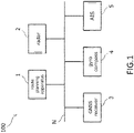
- FIG. 1 is a block diagram showing a configuration example of a ship ICT system 100, in accordance with an embodiment of the present invention.
- the ship ICT system 100 includes a route planning apparatus 1, a radar 2, a GNSS (Global Navigation Satellite System) receiver 3, a gyrocompass 4, and an AIS 5.
- the components of the ship ICT system 100 are connected to a network N for communicating with each other.
- the network N includes but may not be limited to a LAN (Local Area Network).
- the route planning apparatus 1 is an Electronic Chart Display and Information System (herein after ECDIS).
- the route planning apparatus 1 may be a GNSS plotter. A specific configuration example of the route planning apparatus 1 will be described later.
- the route planning apparatus 1 is connected with the radar 2.
- the radar 2 detects a target existing around a corresponding or own ship (hereinafter, the ship) and generates target tracking data (TT data) representing a position and a velocity vector of the target.
- TT data target tracking data
- the GNSS receiver 3 detects the position of the ship based on radio waves received at the GNSS receiver 3. In addition, the GNSS receiver 3 generates position data representing the position of the ship.
- the GNSS receiver 3 is connected with the gyrocompass 4.
- the gyrocompass 4 detects the heading of the ship and generates bearing data showing the heading of the ship.
- a GPS (global positioning system) compass or a magnetic compass may be used to detect the heading of the ship.
- the GNSS receiver 3 is connected to the AIS 5.
- the AIS 5 corresponds to Automatic Identification System that transmits AIS data to surrounding ships and land control centers. Also, the AIS 5 receives AIS data from surrounding ships and land control centers.
- a VDES VHF Data Exchange System
- VHF Data Exchange System may be used in the ship ICT system 100.
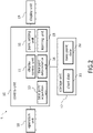
- FIG. 2 is a block diagram of an example configuration of the route planning apparatus 1, in accordance with an embodiment of the present invention.
- the route planning apparatus 1 includes a control unit 10, a storage unit 17, an operation unit 18, and a display unit 19.
- the control unit 10 is a processing circuitry or the control unit 10 comprises a processing circuitry.
- the processing circuitry may be a computing device that includes a CPU, a RAM, a ROM, an input/output interface, and the like.
- the control unit is associated with the storage unit 17.
- the storage unit 17 is an auxiliary storage device such as a nonvolatile memory.
- the CPU of the processing circuitry executes information processing according to a program loaded from the storage unit 17 into the RAM.
- the program may be provided via an information storage medium such as, for example, an optical disk or a memory card, or may be provided via a communication network such as, for example, the Internet or a LAN.
- an information storage medium such as, for example, an optical disk or a memory card
- a communication network such as, for example, the Internet or a LAN.
- the storage unit 17 is configured to store chart data 21, a base point potential database (base point potential DB) 22, and the like.
- the base point DB (Data Base) 22 may be constructed externally and accessed via a communication network such as the Internet.
- the control unit 10 is associated with the operation unit 18 and the display unit 19.
- the operation unit 18 is a pointing device for designating a position in the screen of the display unit 19.
- the operation unit 18 includes but may not be limited to a trackball or a touch sensor.
- the display unit 19 is a display device.
- the display unit 19 includes but may not be limited to a liquid crystal display or an organic electroluminescent display (EL) display.
- the control unit 10 includes a display control unit 11, a point setting unit 12, a base point acquisition unit 13, a base point determination unit 14, and a learning unit 15.
- the CPU of the control unit 10 is configured to execute control processing of each unit of the control unit 10 according to a predetermined program.
- the display control unit 11 is configured to display a list of base points arranged in accordance with a predetermined priority on the screen of the display unit 19. The operation of each unit of the control unit 10 is described in detail later.
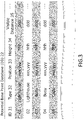
- FIG. 3 is a diagram showing an example of contents of a potential base point database (DB) 22.
- the potential base point DB 22 stores one or more potential base points that may be a base point of a waypoint in association with its position.
- the potential base point DB 22 includes fields such as "ID” 31, "type” 32, "position” 33, "height” 34, and "visible distance” 35.
- the "ID” field 31 is an identifier for identifying base points.
- the "type” field 32 indicates type of the base points.
- the types of base points include, for example, targets such as lighthouses, buoys, capes and the like.
- the "position” field 33 indicates the position of the base point. The position of the base point is shown by position coordinates of latitude and longitude.
- the "height” field 34 indicates the height of the base point.
- the “visible distance” field 35 represents distance of the light of the lighthouse when the potential base point is the lighthouse.
- FIG. 4 is a flowchart showing an example process of the route planning method, in accordance with an embodiment implemented in the route planning apparatus 1 of FIG. 1 .
- the control unit 10 of the route planning apparatus 1 executes information process shown in the FIG. 4 , according to a program.
- FIG.5 and FIG. 6 are views showing an example of screen display, in accordance with an embodiment of the present invention.
- the control unit 10 displays a chart NC on the screen of the display unit 19 based on the chart data 21 stored in the storage unit 17 (S11; processing as the display control unit 11).
- control unit 10 sets a waypoint WP on the chart NC according to the navigator's operation received by the operation unit 18 (S12; processing as the point setting unit 12).
- a pointer AR interlocked with the operation unit 18 is displayed on the screen of the display unit 19, and the waypoint WP is set at a designated position on the chart NC.
- a route RT following the waypoint WP is also displayed on the screen of the display unit 19.
- one or more targets TG such as lighthouses, buoys and capes are also displayed in the chart NC.
- step S12 if it is determined that the waypoint WP is set on the chart NC (S 12: YES), the method proceeds to step S13.
- the control unit 10 extracts a base point within a predetermined range, with the waypoint WP as a reference from the potential base point DB 22. (S13; processing as the base point acquisition unit 13).
- control unit 10 refers to the positions of the base points stored in the potential base point DB 22 and determines whether each base point is located within the range of the waypoint WP or not, and extracts the potential base point located within the range.
- a base point located in a circular range of a predetermined radius centered on the waypoint WP is extracted. It is not limited to this aspect, and for example, an elliptical shape range may be longer in left and right directions (port side to starboard side) than in fore and aft directions (bow to stern) of the ship.
- the control unit 10 calculates the distance and direction from the waypoint WP for each of the extracted potential base points .
- the direction of the potential base point from the waypoint WP is described as an angle with respect to the bow direction of the ship.
- the direction may be 90 degrees to starboard and 270 degrees to port.
- the control unit 10 calculates a predetermined priority for each of the extracted base points.
- the predetermined priority is based on at least one of the distance and the direction of each of the extracted base points from the waypoint WP.
- the predetermined priority may be higher as the distance from the waypoint WP to a corresponding potential base point is closer to the reference distance.
- the predetermined priority may be higher as the direction from the waypoint WP toward the base point is closer to 90 degrees to the bow direction.
- the predetermined priority is shown by the following function f which uses as variables the distance d from the waypoint WP to the potential base point, the direction (angle with respect to the bow direction) 0 of the potential base point from the waypoint WP, the score p set for each type of potential base point, the height h of the potential base point, and the distance dl of the light when the potential base point is a lighthouse.
- ⁇ , ⁇ , ⁇ , and ⁇ are weighting coefficients of each variable.
- the variable "d” may be a difference from or the inverse of a predetermined reference value d 0 .
- the variable " ⁇ " may be a difference from a predetermined reference angle n 0 (for example, 90 degrees) or its inverse.
- the direction (angle with respect to the bow direction) of the potential base point from the waypoint WP is an angle formed by an extension line of a straight line (previous path RT) from the previous waypoint to the waypoint WP, and a straight line connecting the waypoint WP and the potential base point.
- step S16 the control unit 10 displays the extracted symbol and list of the potential base points on the screen of the display unit 19 (S16; Processing as a display control unit).
- a symbol CD representing potential base points are added to the target TG of the potential base point and displayed on the screen of the display unit 19.
- a line DL connecting the waypoint WP and the target TG of the potential base point is displayed between the waypoint WP and the target TG, and a character string KH indicating a distance and a direction is displayed beside the line DL.
- the symbol CD is added to the lighthouse at a distance of 1.5 NM (nautical mile) and a direction of 90 degrees (transverse) with respect to the waypoint WP.
- the symbol CD is added to the buoy at the distance of 0.5 NM and the direction of 320 degrees.
- the symbol CD is added to the lighthouse at the distance of 3.1 NM and the direction of 85 degrees.
- a list LST of the potential base points is displayed on the screen of the display unit 19.
- the potential base points are arranged in the order of the higher predetermined priority.
- the items of the lighthouse at the distance of 1.5 NM in the direction of 90 degrees with respect to the waypoint WP, the buoy at the distance of 0.5 NM in the direction of 320 degrees, and the lighthouse at the distance of 3.1 NM in the direction of 85 degrees are included in the list LST in this order.
- step S17 the control unit 10 checks if the potential base point is selected or not. If the potential base point is not selected, the method is stopped. If the potential base point is selected, the method proceeds to step S18.
- the control unit 10 determines the base point selected by the navigator's operation received by the operation unit 18 among the potential base points displayed on the screen of the display unit 19 (Sections S17 and S18; Processing as the base point determination unit 14) to the base point of the waypoint WP.
- the selection of the base point is determined by designating the item of the base point included in the symbol CD or the list LST indicating the potential base point by the pointer AR.
- a base point near the waypoint is presented to the navigator and the navigator selects the base point accordingly.
- the base points are arranged according to the predetermined priority. Since, the user is required to confirm from the potential base point having the higher predetermined priority, the route planning apparatus 1 enables to determine the base point of the waypoint.
- the highest predetermined priority among the extracted potential base points may be automatically determined as the base points. However, the selection of waypoints and the base points is based on the experience of the navigator. Further, the potential base point is presented to the navigator and the navigator's selection is accepted.
- control unit 10 may adjust the predetermined priority based on the selection result by the navigator (or user) (processing as the learning unit 15). In other words, when the base points of second or later priority are selected, the weighting coefficient of the function for calculating the predetermined priority may be further optimized.
- the adjustment of the predetermined priority may be realized, for example, by performing supervised learning using the learning unit 15 (shown in FIG. 2 ), in which the selected potential base points are set as the correct answer.
Landscapes
- Engineering & Computer Science (AREA)
- Radar, Positioning & Navigation (AREA)
- Remote Sensing (AREA)
- Ocean & Marine Engineering (AREA)
- Physics & Mathematics (AREA)
- General Physics & Mathematics (AREA)
- Chemical & Material Sciences (AREA)
- Combustion & Propulsion (AREA)
- Mechanical Engineering (AREA)
- Automation & Control Theory (AREA)
- Navigation (AREA)
- Traffic Control Systems (AREA)
Abstract
Description
- The present invention mainly relates to a route planning apparatus for planning a navigation route in water, a route planning method for planning the navigation in water, and a route planning program for executing a function for planning the navigation route in water.
- Conventionally, route planning devices are equipped in movable bodies (such as, automobiles, ships, airplanes) to display a route to be navigated by a user. The user inputs a departure location and a destination location to get the desired route from the route planning device. For example, the route planning devices equipped in automobiles are stored with maps, and based on the maps, these devices display various kinds of routes according to the user requirement.
Patent Document 1 discloses such a route planning device. -
Patent Document 1 discloses a route planning apparatus comprising: a display unit for displaying a route to be navigated planned by a user on a chart; a date/time input unit for receiving input of a navigation date/time of the route; a caution information reading unit for reading caution information affecting navigation and information associated with a position and a date/time based on the navigation date/time input; and a route verification unit for extracting the caution information located at least on the route or near the route based on the position indicated by the caution information read by the caution information reading unit and the position of the route, and verifying the route based on the extracted caution information. As used herein, thepatent document 1 isJP6076611B2 - In a route planning, waypoints are established with base points in accordance with the waypoints. The base points may correspond to landmarks such as lighthouses, buoys, capes and the like. The base points are the landmarks that are easily identifiable by a navigator onboard. The navigator onboard picks up and selects such a base point and sets a waypoint on the basis of the base point.
- In a case of route planning by ECDIS (Electronic Chart Display and Information System), there is a need to set up waypoints and base points along with distances and directions from waypoints to base points. In a conventional ECDIS, the navigator onboard manually finds and selects an appropriate base point. Next, the navigator onboard sets a waypoint while checking the distance and direction from the base point to the waypoint. These procedures are complicated.
- The present invention is made in view of the above problems. The objective of the present invention is to provide a route planning apparatus that enables to set a waypoint and the corresponding base point with ease.
- To solve the problem mentioned above, a route planning apparatus according to one embodiment of the present invention comprises: a display unit that is configured to display a chart on a screen; and an operation unit that is configured to designate a position on the screen. In addition, the route planning apparatus comprises a storage unit configured to store one or a plurality of potential base points that can be a base point of a waypoint in association with their positions; a waypoint setting unit configured to set waypoints on the chart in response to a navigator's operation received by the operation unit; a base point acquisition unit configured to extract the base points located within a predetermined range with the set waypoint as a reference from the storage unit; and a base point determination unit that is configured to determine a selected base point to set the base point of the set waypoint.
- According to another embodiment of the present invention, a route planning method is provided. The route planning method includes setting waypoints on a chart based on a navigator's operation. The route planning method includes extracting potential base points located within a range of reference to the set waypoints. The potential base points can be base points of corresponding waypoints. The route planning method includes determining an extracted base point to be the base point of the set waypoint.
- According to another embodiment of the present invention, a computer program, when executed by one or more processors, cause a computing device to perform a method that comprises: setting a waypoint on a chart, selecting potential base points of the waypoint within the range with the set waypoint as a reference from one or more potential base points associated with corresponding position of the set waypoint, and determining the set base point of the waypoint from the selected potential base points.
- According to the present invention, waypoints for planning a navigation route and their potential base points can be set with ease.
- The present invention is illustrated by way of example and not by way of limitation in the figures of the accompanying drawings, in which the like reference numerals indicate like elements and in which:
-
FIG. 1 is a diagram showing a configuration example of a ship ICT (Information and Communication Technology) system, in accordance with an embodiment of the present invention; -
FIG. 2 is a diagram showing a configuration example of a route planning apparatus, in accordance with an embodiment of the present invention; -
FIG. 3 is a diagram showing an example of the contents of a database, in accordance with an embodiment of the present invention; -
FIG. 4 is a diagram showing an example process of the route planning method, in accordance with an embodiment of the present invention; -
FIG. 5 is a diagram showing an example of a screen display, in accordance with an embodiment of the present invention; and -
FIG. 6 shows an example of a screen display, in accordance with an embodiment of the present invention. - Embodiments of the present invention will be described below with reference to the drawings.
-
FIG. 1 is a block diagram showing a configuration example of aship ICT system 100, in accordance with an embodiment of the present invention. Theship ICT system 100 includes aroute planning apparatus 1, aradar 2, a GNSS (Global Navigation Satellite System)receiver 3, a gyrocompass 4, and an AIS 5. The components of theship ICT system 100 are connected to a network N for communicating with each other. The network N includes but may not be limited to a LAN (Local Area Network). - The
route planning apparatus 1 is an Electronic Chart Display and Information System (herein after ECDIS). Theroute planning apparatus 1 may be a GNSS plotter. A specific configuration example of theroute planning apparatus 1 will be described later. - The
route planning apparatus 1 is connected with theradar 2. Theradar 2 detects a target existing around a corresponding or own ship (hereinafter, the ship) and generates target tracking data (TT data) representing a position and a velocity vector of the target. - Further, the GNSS
receiver 3 detects the position of the ship based on radio waves received at theGNSS receiver 3. In addition, the GNSSreceiver 3 generates position data representing the position of the ship. - The GNSS
receiver 3 is connected with the gyrocompass 4. The gyrocompass 4 detects the heading of the ship and generates bearing data showing the heading of the ship. Alternatively, a GPS (global positioning system) compass or a magnetic compass may be used to detect the heading of the ship. - The GNSS
receiver 3 is connected to the AIS 5. The AIS 5 corresponds to Automatic Identification System that transmits AIS data to surrounding ships and land control centers. Also, the AIS 5 receives AIS data from surrounding ships and land control centers. In addition, a VDES (VHF Data Exchange System) may be used in theship ICT system 100. -
FIG. 2 is a block diagram of an example configuration of theroute planning apparatus 1, in accordance with an embodiment of the present invention. As shown inFIG. 2 , theroute planning apparatus 1 includes acontrol unit 10, astorage unit 17, anoperation unit 18, and adisplay unit 19. - The
control unit 10 is a processing circuitry or thecontrol unit 10 comprises a processing circuitry. The processing circuitry may be a computing device that includes a CPU, a RAM, a ROM, an input/output interface, and the like. The control unit is associated with thestorage unit 17. Thestorage unit 17 is an auxiliary storage device such as a nonvolatile memory. In an example, the CPU of the processing circuitry executes information processing according to a program loaded from thestorage unit 17 into the RAM. - In accordance with an embodiment, the program may be provided via an information storage medium such as, for example, an optical disk or a memory card, or may be provided via a communication network such as, for example, the Internet or a LAN.
- In addition to the program, the
storage unit 17 is configured to storechart data 21, a base point potential database (base point potential DB) 22, and the like. The base point DB (Data Base) 22 may be constructed externally and accessed via a communication network such as the Internet. - The
control unit 10 is associated with theoperation unit 18 and thedisplay unit 19. Theoperation unit 18 is a pointing device for designating a position in the screen of thedisplay unit 19. Theoperation unit 18 includes but may not be limited to a trackball or a touch sensor. Thedisplay unit 19 is a display device. Thedisplay unit 19 includes but may not be limited to a liquid crystal display or an organic electroluminescent display (EL) display. - The
control unit 10 includes adisplay control unit 11, apoint setting unit 12, a basepoint acquisition unit 13, a basepoint determination unit 14, and alearning unit 15. The CPU of thecontrol unit 10 is configured to execute control processing of each unit of thecontrol unit 10 according to a predetermined program. Thedisplay control unit 11 is configured to display a list of base points arranged in accordance with a predetermined priority on the screen of thedisplay unit 19. The operation of each unit of thecontrol unit 10 is described in detail later. -
FIG. 3 is a diagram showing an example of contents of a potential base point database (DB) 22. The potentialbase point DB 22 stores one or more potential base points that may be a base point of a waypoint in association with its position. The potentialbase point DB 22 includes fields such as "ID" 31, "type" 32, "position" 33, "height" 34, and "visible distance" 35. - The "ID"
field 31 is an identifier for identifying base points. The "type"field 32 indicates type of the base points. The types of base points include, for example, targets such as lighthouses, buoys, capes and the like. The "position"field 33 indicates the position of the base point. The position of the base point is shown by position coordinates of latitude and longitude. - The "height"
field 34 indicates the height of the base point. The "visible distance"field 35 represents distance of the light of the lighthouse when the potential base point is the lighthouse. -
FIG. 4 is a flowchart showing an example process of the route planning method, in accordance with an embodiment implemented in theroute planning apparatus 1 ofFIG. 1 . Thecontrol unit 10 of theroute planning apparatus 1 executes information process shown in theFIG. 4 , according to a program.FIG.5 andFIG. 6 are views showing an example of screen display, in accordance with an embodiment of the present invention. - At step of S11, the
control unit 10 displays a chart NC on the screen of thedisplay unit 19 based on thechart data 21 stored in the storage unit 17 (S11; processing as the display control unit 11). - Next, at step of S12, the
control unit 10 sets a waypoint WP on the chart NC according to the navigator's operation received by the operation unit 18 (S12; processing as the point setting unit 12). - As shown in
FIG. 5 , a pointer AR interlocked with theoperation unit 18 is displayed on the screen of thedisplay unit 19, and the waypoint WP is set at a designated position on the chart NC. A route RT following the waypoint WP is also displayed on the screen of thedisplay unit 19. Further, one or more targets TG such as lighthouses, buoys and capes are also displayed in the chart NC. - Returning to
FIG. 4 , at step S12 if it is determined that the waypoint WP is set on the chart NC (S 12: YES), the method proceeds to step S13. At step S13, thecontrol unit 10 extracts a base point within a predetermined range, with the waypoint WP as a reference from the potentialbase point DB 22. (S13; processing as the base point acquisition unit 13). - Specifically, the
control unit 10 refers to the positions of the base points stored in the potentialbase point DB 22 and determines whether each base point is located within the range of the waypoint WP or not, and extracts the potential base point located within the range. - For example, a base point located in a circular range of a predetermined radius centered on the waypoint WP is extracted. It is not limited to this aspect, and for example, an elliptical shape range may be longer in left and right directions (port side to starboard side) than in fore and aft directions (bow to stern) of the ship.
- Next, at step S14, the
control unit 10 calculates the distance and direction from the waypoint WP for each of the extracted potential base points . The direction of the potential base point from the waypoint WP is described as an angle with respect to the bow direction of the ship. For example, the direction may be 90 degrees to starboard and 270 degrees to port. - At step S15, the
control unit 10 calculates a predetermined priority for each of the extracted base points. The predetermined priority is based on at least one of the distance and the direction of each of the extracted base points from the waypoint WP. - Specifically, the predetermined priority may be higher as the distance from the waypoint WP to a corresponding potential base point is closer to the reference distance. The predetermined priority may be higher as the direction from the waypoint WP toward the base point is closer to 90 degrees to the bow direction.
- For example, the predetermined priority is shown by the following function f which uses as variables the distance d from the waypoint WP to the potential base point, the direction (angle with respect to the bow direction) 0 of the potential base point from the waypoint WP, the score p set for each type of potential base point, the height h of the potential base point, and the distance dl of the light when the potential base point is a lighthouse. The function f is defined as:

- The larger or smaller is the value of the function f, the higher is the predetermined priority. Here, α, β, γ, δ, and ε are weighting coefficients of each variable.
- The variable "d" may be a difference from or the inverse of a predetermined reference value d0. The variable "θ" may be a difference from a predetermined reference angle n0 (for example, 90 degrees) or its inverse.
- The direction (angle with respect to the bow direction) of the potential base point from the waypoint WP is an angle formed by an extension line of a straight line (previous path RT) from the previous waypoint to the waypoint WP, and a straight line connecting the waypoint WP and the potential base point.
- Next, at step S16, the
control unit 10 displays the extracted symbol and list of the potential base points on the screen of the display unit 19 (S16; Processing as a display control unit). - As shown in
FIG. 6 , a symbol CD representing potential base points are added to the target TG of the potential base point and displayed on the screen of thedisplay unit 19. A line DL connecting the waypoint WP and the target TG of the potential base point is displayed between the waypoint WP and the target TG, and a character string KH indicating a distance and a direction is displayed beside the line DL. - In the example shown in the
FIG. 6 , the symbol CD is added to the lighthouse at a distance of 1.5 NM (nautical mile) and a direction of 90 degrees (transverse) with respect to the waypoint WP. In addition, the symbol CD is added to the buoy at the distance of 0.5 NM and the direction of 320 degrees. Further, the symbol CD is added to the lighthouse at the distance of 3.1 NM and the direction of 85 degrees. - Further, a list LST of the potential base points is displayed on the screen of the
display unit 19. In the list LST, the potential base points are arranged in the order of the higher predetermined priority. - In the example shown in the
FIG. 6 , the items of the lighthouse at the distance of 1.5 NM in the direction of 90 degrees with respect to the waypoint WP, the buoy at the distance of 0.5 NM in the direction of 320 degrees, and the lighthouse at the distance of 3.1 NM in the direction of 85 degrees are included in the list LST in this order. - At step S17, the
control unit 10 checks if the potential base point is selected or not. If the potential base point is not selected, the method is stopped. If the potential base point is selected, the method proceeds to step S18. - Referring back to
FIG. 4 , next, at step of S18, thecontrol unit 10 determines the base point selected by the navigator's operation received by theoperation unit 18 among the potential base points displayed on the screen of the display unit 19 (Sections S17 and S18; Processing as the base point determination unit 14) to the base point of the waypoint WP. - As shown in
FIG. 6 , the selection of the base point is determined by designating the item of the base point included in the symbol CD or the list LST indicating the potential base point by the pointer AR. - In order to avoid the screen display clutter, only the symbol CD corresponding to the item of the potential base point selected in the list LST may be identified and displayed as the other symbol CD, and the line DL and the character string KH may be added.
- According to the embodiment described above, when a waypoint is set, a base point near the waypoint is presented to the navigator and the navigator selects the base point accordingly.. In the list presented to the navigator, the base points are arranged according to the predetermined priority. Since, the user is required to confirm from the potential base point having the higher predetermined priority, the
route planning apparatus 1 enables to determine the base point of the waypoint. - The highest predetermined priority among the extracted potential base points may be automatically determined as the base points. However, the selection of waypoints and the base points is based on the experience of the navigator. Further, the potential base point is presented to the navigator and the navigator's selection is accepted.
- In some embodiments, the
control unit 10 may adjust the predetermined priority based on the selection result by the navigator (or user) (processing as the learning unit 15). In other words, when the base points of second or later priority are selected, the weighting coefficient of the function for calculating the predetermined priority may be further optimized. The adjustment of the predetermined priority may be realized, for example, by performing supervised learning using the learning unit 15 (shown inFIG. 2 ), in which the selected potential base points are set as the correct answer. - Although the embodiments of the present invention have been described above, the present invention is not limited to the embodiments described above. Needless to say, it is possible for those skilled in the art to make various modifications.
-
- (1) Route planning apparatus,
- (2) Radar,
- (3) GNSS receiver,
- (4) Gyrocompass,
- (5) AIS,
- (10) control unit,
- (11) Display control unit,
- (12) Point setting unit,
- (13) Base point acquisition unit,
- (14) Base point determination unit,
- (15) Learning unit,
- (17) Storage unit,
- (18) Operation unit,
- (19) Display unit,
- (100) Ship ICT system
Claims (9)
- A route planning apparatus (1) for planning a navigation route of a ship, comprising:a display unit (19) for displaying a chart on a screen;an operation unit (18) configured to designate a position in the screen;a storage unit (17) configured to store one or more potential base points that can be a potential base point associated with corresponding position of a waypoint;a point setting unit (12) to configured to set the waypoint on the chart in response to a navigator's operation received by the operation unit(18);a base point acquisition unit (13) configured to extract base points within a predetermined range of the set waypoint as a reference, from the storage unit (17); anda base point determination unit (14) configured to determine at least one of the extracted potential base points to be the base point of the set waypoint.
- The route planning apparatus (1) of claim 1; further comprising,
a display control unit (11) configured to display the extracted potential base point on the screen of the display unit (19);
the base point determination unit (14) is configured to determine the at least one base point as selected among the base points displayed on the screen of the display unit (19) by the navigator's operation received by the operation unit (18) to set the waypoint. - The route planning apparatus (1) of claim 2; wherein,
the display control unit (11) is configured to display a list of the base points arranged in accordance with a predetermined priority on the screen of the display unit (19). - The route planning apparatus (1) of claim 3; wherein,
the predetermined priority is based on a distance between the corresponding base point and the waypoint, or a direction of the corresponding base point from the waypoint. - The route planning apparatus (1) of claim 3; wherein,
the higher the distance from the waypoint is closer to a reference distance, the higher the predetermined priority. - The route planning apparatus (1) of claim 3; wherein,
the predetermined priority increases as the direction from the waypoint is closer to 90 degrees with respect to a bow direction of the ship. - The route planning apparatus (1) of claim 3, further comprising:
a learning unit (15) configured to adjust the predetermined priority based on a selection result by the navigator. - A route planning method, comprising:setting waypoints on a chart based on a navigator's operation;extracting potential base points located within the range of reference to the set waypoint, from one or more potential base points associated with corresponding position of the set waypoint; anddetermining the extracted potential base point to be a base point of the set waypoint.
- A computer program, when executed by one or more processors, cause a computing device to perform a method that comprises:setting waypoints on a chart based on a navigator's operation;extracting potential base points located within a range of reference to the set waypoint, from one or more potential base points associated with corresponding position of the set waypoint; anddetermining the extracted potential base point to be a base point of the set waypoint.
Applications Claiming Priority (2)
| Application Number | Priority Date | Filing Date | Title |
|---|---|---|---|
| JP2020021623 | 2020-02-12 | ||
| PCT/JP2021/000479 WO2021161696A1 (en) | 2020-02-12 | 2021-01-08 | Seaway planning device, seaway planning method, and program |
Publications (3)
| Publication Number | Publication Date |
|---|---|
| EP4105909A1 true EP4105909A1 (en) | 2022-12-21 |
| EP4105909A4 EP4105909A4 (en) | 2024-03-20 |
| EP4105909B1 EP4105909B1 (en) | 2026-02-25 |
Family
ID=77292158
Family Applications (1)
| Application Number | Title | Priority Date | Filing Date |
|---|---|---|---|
| EP21752960.1A Active EP4105909B1 (en) | 2020-02-12 | 2021-01-08 | Seaway planning device, seaway planning method, and program |
Country Status (5)
| Country | Link |
|---|---|
| US (1) | US12140433B2 (en) |
| EP (1) | EP4105909B1 (en) |
| JP (1) | JP7518890B2 (en) |
| CN (1) | CN114930426A (en) |
| WO (1) | WO2021161696A1 (en) |
Families Citing this family (1)
| Publication number | Priority date | Publication date | Assignee | Title |
|---|---|---|---|---|
| CN114664118B (en) * | 2022-03-18 | 2023-04-07 | 陕西正整数科技有限公司 | Intelligent ship collision avoidance automatic test scene generation method and system |
Family Cites Families (16)
| Publication number | Priority date | Publication date | Assignee | Title |
|---|---|---|---|---|
| JP2003035557A (en) * | 2001-07-23 | 2003-02-07 | Yokogawa Denshikiki Co Ltd | Electronic chart device |
| KR100943815B1 (en) * | 2004-12-27 | 2010-02-25 | 현대중공업 주식회사 | Test method of ship navigation equipment using GI data |
| JP6076611B2 (en) | 2012-04-11 | 2017-02-08 | 古野電気株式会社 | Route planning apparatus and route plan verification method |
| JP6288933B2 (en) * | 2013-04-12 | 2018-03-07 | 古野電気株式会社 | Route display device and route display method |
| US9002637B2 (en) * | 2013-04-16 | 2015-04-07 | The Boeing Company | Systems and methods for generating a navigation chart |
| JP6425913B2 (en) * | 2014-05-13 | 2018-11-21 | 古野電気株式会社 | Information display device |
| JP2015215278A (en) * | 2014-05-13 | 2015-12-03 | 古野電気株式会社 | Information display device |
| US9766077B2 (en) * | 2014-09-30 | 2017-09-19 | Garmin Switzerland Gmbh | Navigational guidance for crossing a boundary line |
| JP6408869B2 (en) * | 2014-10-31 | 2018-10-17 | 古野電気株式会社 | Remote notification device, information remote notification system, and information remote notification method |
| JP6953108B2 (en) * | 2015-09-08 | 2021-10-27 | 古野電気株式会社 | Information display device and information display method |
| CN105890608B (en) * | 2016-03-31 | 2020-08-21 | 百度在线网络技术(北京)有限公司 | Navigation reference point determining method and device and navigation method and device |
| CN106871897B (en) * | 2016-12-30 | 2020-04-24 | 中国船舶重工集团公司第七0七研究所 | Route making method for automatically associating waypoint library |
| JP6882042B2 (en) * | 2017-04-06 | 2021-06-02 | ヤマハ発動機株式会社 | Server system and method |
| CN109556612B (en) * | 2017-09-26 | 2022-03-08 | 腾讯科技(深圳)有限公司 | A navigation information processing method, device, server, terminal and storage medium |
| EP3734968A4 (en) * | 2017-12-25 | 2021-05-05 | Furuno Electric Co., Ltd. | Video generation device and video generation method |
| US20230123565A1 (en) * | 2021-10-14 | 2023-04-20 | Furuno Electric Co., Ltd. | Track management device and method |
-
2021
- 2021-01-08 CN CN202180008263.5A patent/CN114930426A/en active Pending
- 2021-01-08 WO PCT/JP2021/000479 patent/WO2021161696A1/en not_active Ceased
- 2021-01-08 JP JP2022500264A patent/JP7518890B2/en active Active
- 2021-01-08 EP EP21752960.1A patent/EP4105909B1/en active Active
-
2022
- 2022-07-28 US US17/875,416 patent/US12140433B2/en active Active
Also Published As
| Publication number | Publication date |
|---|---|
| US12140433B2 (en) | 2024-11-12 |
| WO2021161696A1 (en) | 2021-08-19 |
| EP4105909B1 (en) | 2026-02-25 |
| JP7518890B2 (en) | 2024-07-18 |
| EP4105909A4 (en) | 2024-03-20 |
| CN114930426A (en) | 2022-08-19 |
| US20220364865A1 (en) | 2022-11-17 |
| JPWO2021161696A1 (en) | 2021-08-19 |
Similar Documents
| Publication | Publication Date | Title |
|---|---|---|
| US10077983B2 (en) | Information display device and method | |
| US6181302B1 (en) | Marine navigation binoculars with virtual display superimposing real world image | |
| JP6288933B2 (en) | Route display device and route display method | |
| US9030353B2 (en) | Information display device, information display method, and radar apparatus | |
| US20150330804A1 (en) | Information display device and method | |
| US5786849A (en) | Marine navigation I | |
| EP2792998B1 (en) | Systems and methods for generating a navigation chart | |
| US20100207845A1 (en) | Methods and systems for displaying an object having an associated beacon signal | |
| US20120203519A1 (en) | Method for calculating a navigation phase in a navigation system involving terrain correlation | |
| EP2840357B1 (en) | Vehicle position validation | |
| EP4270360A1 (en) | Sea mark identification device, autonomous navigation system, sea mark identification method, and program | |
| JP7813725B2 (en) | Navigational Aids Identification Device, Autonomous Navigation System, Navigational Aids Identification Method, and Program | |
| JP2025186506A (en) | Navigation information display device, navigation information display method, and program | |
| US12140433B2 (en) | Apparatus and method for route planning | |
| WO2014081351A1 (en) | Method for improving the accuracy of a radio based navigation system | |
| CN117280396A (en) | Ship monitoring device, ship monitoring method and program | |
| US20260100132A1 (en) | Navigation assistance device, navigation assistance method, and non-transitory computer-readable recording medium | |
| EP2047291B1 (en) | Radar display and processing apparatus | |
| US20250044102A1 (en) | Marine navigation system | |
| JP7550210B2 (en) | Route planning device, route planning method, and program | |
| CN116149526A (en) | Object mark information display device, object mark information display method and program | |
| KR20240080481A (en) | Apparatus for visualizing navigation route using navigation data and method thereof | |
| KR20260056080A (en) | Electronic device for identifying maritime target based on coordinate transformation of maritime sensor information, and operation method thereof | |
| Soper et al. | US Navy issues in electronic navigation: transitioning from" traditional" to" digital navigation" | |
| JP2026075555A (en) | Information processing device, information processing method, and program |
Legal Events
| Date | Code | Title | Description |
|---|---|---|---|
| STAA | Information on the status of an ep patent application or granted ep patent |
Free format text: STATUS: THE INTERNATIONAL PUBLICATION HAS BEEN MADE |
|
| PUAI | Public reference made under article 153(3) epc to a published international application that has entered the european phase |
Free format text: ORIGINAL CODE: 0009012 |
|
| STAA | Information on the status of an ep patent application or granted ep patent |
Free format text: STATUS: REQUEST FOR EXAMINATION WAS MADE |
|
| 17P | Request for examination filed |
Effective date: 20220627 |
|
| AK | Designated contracting states |
Kind code of ref document: A1 Designated state(s): AL AT BE BG CH CY CZ DE DK EE ES FI FR GB GR HR HU IE IS IT LI LT LU LV MC MK MT NL NO PL PT RO RS SE SI SK SM TR |
|
| DAV | Request for validation of the european patent (deleted) | ||
| DAX | Request for extension of the european patent (deleted) | ||
| A4 | Supplementary search report drawn up and despatched |
Effective date: 20240214 |
|
| RIC1 | Information provided on ipc code assigned before grant |
Ipc: G01C 21/20 20060101ALI20240209BHEP Ipc: B63B 79/40 20200101ALI20240209BHEP Ipc: G01C 21/36 20060101ALI20240209BHEP Ipc: G08G 3/00 20060101AFI20240209BHEP |
|
| STAA | Information on the status of an ep patent application or granted ep patent |
Free format text: STATUS: EXAMINATION IS IN PROGRESS |
|
| 17Q | First examination report despatched |
Effective date: 20241122 |
|
| GRAP | Despatch of communication of intention to grant a patent |
Free format text: ORIGINAL CODE: EPIDOSNIGR1 |
|
| STAA | Information on the status of an ep patent application or granted ep patent |
Free format text: STATUS: GRANT OF PATENT IS INTENDED |
|
| INTG | Intention to grant announced |
Effective date: 20250911 |
|
| GRAS | Grant fee paid |
Free format text: ORIGINAL CODE: EPIDOSNIGR3 |
|
| GRAA | (expected) grant |
Free format text: ORIGINAL CODE: 0009210 |
|
| STAA | Information on the status of an ep patent application or granted ep patent |
Free format text: STATUS: THE PATENT HAS BEEN GRANTED |
|
| AK | Designated contracting states |
Kind code of ref document: B1 Designated state(s): AL AT BE BG CH CY CZ DE DK EE ES FI FR GB GR HR HU IE IS IT LI LT LU LV MC MK MT NL NO PL PT RO RS SE SI SK SM TR |
|
| REG | Reference to a national code |
Ref country code: CH Ref legal event code: F10 Free format text: ST27 STATUS EVENT CODE: U-0-0-F10-F00 (AS PROVIDED BY THE NATIONAL OFFICE) Effective date: 20260225 Ref country code: GB Ref legal event code: FG4D |
|
| REG | Reference to a national code |
Ref country code: DE Ref legal event code: R096 Ref document number: 602021048690 Country of ref document: DE |
|
| REG | Reference to a national code |
Ref country code: IE Ref legal event code: FG4D |