EP4105677A1 - System and method for processing radar signal - Google Patents
System and method for processing radar signal Download PDFInfo
- Publication number
- EP4105677A1 EP4105677A1 EP21195808.7A EP21195808A EP4105677A1 EP 4105677 A1 EP4105677 A1 EP 4105677A1 EP 21195808 A EP21195808 A EP 21195808A EP 4105677 A1 EP4105677 A1 EP 4105677A1
- Authority
- EP
- European Patent Office
- Prior art keywords
- signal
- radar
- interference
- radar signal
- module
- Prior art date
- Legal status (The legal status is an assumption and is not a legal conclusion. Google has not performed a legal analysis and makes no representation as to the accuracy of the status listed.)
- Granted
Links
Images


Classifications
-
- G—PHYSICS
- G01—MEASURING; TESTING
- G01S—RADIO DIRECTION-FINDING; RADIO NAVIGATION; DETERMINING DISTANCE OR VELOCITY BY USE OF RADIO WAVES; LOCATING OR PRESENCE-DETECTING BY USE OF THE REFLECTION OR RERADIATION OF RADIO WAVES; ANALOGOUS ARRANGEMENTS USING OTHER WAVES
- G01S7/00—Details of systems according to groups G01S13/00, G01S15/00, G01S17/00
- G01S7/02—Details of systems according to groups G01S13/00, G01S15/00, G01S17/00 of systems according to group G01S13/00
- G01S7/28—Details of pulse systems
- G01S7/2813—Means providing a modification of the radiation pattern for cancelling noise, clutter or interfering signals, e.g. side lobe suppression, side lobe blanking, null-steering arrays
-
- G—PHYSICS
- G01—MEASURING; TESTING
- G01S—RADIO DIRECTION-FINDING; RADIO NAVIGATION; DETERMINING DISTANCE OR VELOCITY BY USE OF RADIO WAVES; LOCATING OR PRESENCE-DETECTING BY USE OF THE REFLECTION OR RERADIATION OF RADIO WAVES; ANALOGOUS ARRANGEMENTS USING OTHER WAVES
- G01S7/00—Details of systems according to groups G01S13/00, G01S15/00, G01S17/00
- G01S7/02—Details of systems according to groups G01S13/00, G01S15/00, G01S17/00 of systems according to group G01S13/00
- G01S7/28—Details of pulse systems
- G01S7/285—Receivers
- G01S7/292—Extracting wanted echo-signals
- G01S7/2923—Extracting wanted echo-signals based on data belonging to a number of consecutive radar periods
-
- G—PHYSICS
- G01—MEASURING; TESTING
- G01S—RADIO DIRECTION-FINDING; RADIO NAVIGATION; DETERMINING DISTANCE OR VELOCITY BY USE OF RADIO WAVES; LOCATING OR PRESENCE-DETECTING BY USE OF THE REFLECTION OR RERADIATION OF RADIO WAVES; ANALOGOUS ARRANGEMENTS USING OTHER WAVES
- G01S7/00—Details of systems according to groups G01S13/00, G01S15/00, G01S17/00
- G01S7/02—Details of systems according to groups G01S13/00, G01S15/00, G01S17/00 of systems according to group G01S13/00
- G01S7/40—Means for monitoring or calibrating
- G01S7/4052—Means for monitoring or calibrating by simulation of echoes
- G01S7/4056—Means for monitoring or calibrating by simulation of echoes specially adapted to FMCW
-
- G—PHYSICS
- G01—MEASURING; TESTING
- G01S—RADIO DIRECTION-FINDING; RADIO NAVIGATION; DETERMINING DISTANCE OR VELOCITY BY USE OF RADIO WAVES; LOCATING OR PRESENCE-DETECTING BY USE OF THE REFLECTION OR RERADIATION OF RADIO WAVES; ANALOGOUS ARRANGEMENTS USING OTHER WAVES
- G01S13/00—Systems using the reflection or reradiation of radio waves, e.g. radar systems; Analogous systems using reflection or reradiation of waves whose nature or wavelength is irrelevant or unspecified
- G01S13/02—Systems using reflection of radio waves, e.g. primary radar systems; Analogous systems
- G01S13/06—Systems determining position data of a target
- G01S13/08—Systems for measuring distance only
- G01S13/32—Systems for measuring distance only using transmission of continuous waves, whether amplitude-, frequency-, or phase-modulated, or unmodulated
- G01S13/34—Systems for measuring distance only using transmission of continuous waves, whether amplitude-, frequency-, or phase-modulated, or unmodulated using transmission of continuous, frequency-modulated waves while heterodyning the received signal, or a signal derived therefrom, with a locally-generated signal related to the contemporaneously transmitted signal
-
- G—PHYSICS
- G01—MEASURING; TESTING
- G01S—RADIO DIRECTION-FINDING; RADIO NAVIGATION; DETERMINING DISTANCE OR VELOCITY BY USE OF RADIO WAVES; LOCATING OR PRESENCE-DETECTING BY USE OF THE REFLECTION OR RERADIATION OF RADIO WAVES; ANALOGOUS ARRANGEMENTS USING OTHER WAVES
- G01S13/00—Systems using the reflection or reradiation of radio waves, e.g. radar systems; Analogous systems using reflection or reradiation of waves whose nature or wavelength is irrelevant or unspecified
- G01S13/02—Systems using reflection of radio waves, e.g. primary radar systems; Analogous systems
- G01S13/06—Systems determining position data of a target
- G01S13/08—Systems for measuring distance only
- G01S13/32—Systems for measuring distance only using transmission of continuous waves, whether amplitude-, frequency-, or phase-modulated, or unmodulated
- G01S13/34—Systems for measuring distance only using transmission of continuous waves, whether amplitude-, frequency-, or phase-modulated, or unmodulated using transmission of continuous, frequency-modulated waves while heterodyning the received signal, or a signal derived therefrom, with a locally-generated signal related to the contemporaneously transmitted signal
- G01S13/343—Systems for measuring distance only using transmission of continuous waves, whether amplitude-, frequency-, or phase-modulated, or unmodulated using transmission of continuous, frequency-modulated waves while heterodyning the received signal, or a signal derived therefrom, with a locally-generated signal related to the contemporaneously transmitted signal using sawtooth modulation
-
- G—PHYSICS
- G01—MEASURING; TESTING
- G01S—RADIO DIRECTION-FINDING; RADIO NAVIGATION; DETERMINING DISTANCE OR VELOCITY BY USE OF RADIO WAVES; LOCATING OR PRESENCE-DETECTING BY USE OF THE REFLECTION OR RERADIATION OF RADIO WAVES; ANALOGOUS ARRANGEMENTS USING OTHER WAVES
- G01S13/00—Systems using the reflection or reradiation of radio waves, e.g. radar systems; Analogous systems using reflection or reradiation of waves whose nature or wavelength is irrelevant or unspecified
- G01S13/02—Systems using reflection of radio waves, e.g. primary radar systems; Analogous systems
- G01S13/06—Systems determining position data of a target
- G01S13/08—Systems for measuring distance only
- G01S13/32—Systems for measuring distance only using transmission of continuous waves, whether amplitude-, frequency-, or phase-modulated, or unmodulated
- G01S13/34—Systems for measuring distance only using transmission of continuous waves, whether amplitude-, frequency-, or phase-modulated, or unmodulated using transmission of continuous, frequency-modulated waves while heterodyning the received signal, or a signal derived therefrom, with a locally-generated signal related to the contemporaneously transmitted signal
- G01S13/345—Systems for measuring distance only using transmission of continuous waves, whether amplitude-, frequency-, or phase-modulated, or unmodulated using transmission of continuous, frequency-modulated waves while heterodyning the received signal, or a signal derived therefrom, with a locally-generated signal related to the contemporaneously transmitted signal using triangular modulation
-
- G—PHYSICS
- G01—MEASURING; TESTING
- G01S—RADIO DIRECTION-FINDING; RADIO NAVIGATION; DETERMINING DISTANCE OR VELOCITY BY USE OF RADIO WAVES; LOCATING OR PRESENCE-DETECTING BY USE OF THE REFLECTION OR RERADIATION OF RADIO WAVES; ANALOGOUS ARRANGEMENTS USING OTHER WAVES
- G01S13/00—Systems using the reflection or reradiation of radio waves, e.g. radar systems; Analogous systems using reflection or reradiation of waves whose nature or wavelength is irrelevant or unspecified
- G01S13/02—Systems using reflection of radio waves, e.g. primary radar systems; Analogous systems
- G01S13/50—Systems of measurement based on relative movement of target
- G01S13/505—Systems of measurement based on relative movement of target using Doppler effect for determining closest range to a target or corresponding time, e.g. miss-distance indicator
-
- G—PHYSICS
- G01—MEASURING; TESTING
- G01S—RADIO DIRECTION-FINDING; RADIO NAVIGATION; DETERMINING DISTANCE OR VELOCITY BY USE OF RADIO WAVES; LOCATING OR PRESENCE-DETECTING BY USE OF THE REFLECTION OR RERADIATION OF RADIO WAVES; ANALOGOUS ARRANGEMENTS USING OTHER WAVES
- G01S13/00—Systems using the reflection or reradiation of radio waves, e.g. radar systems; Analogous systems using reflection or reradiation of waves whose nature or wavelength is irrelevant or unspecified
- G01S13/02—Systems using reflection of radio waves, e.g. primary radar systems; Analogous systems
- G01S13/50—Systems of measurement based on relative movement of target
- G01S13/58—Velocity or trajectory determination systems; Sense-of-movement determination systems
- G01S13/581—Velocity or trajectory determination systems; Sense-of-movement determination systems using transmission of interrupted pulse modulated waves and based upon the Doppler effect resulting from movement of targets
- G01S13/582—Velocity or trajectory determination systems; Sense-of-movement determination systems using transmission of interrupted pulse modulated waves and based upon the Doppler effect resulting from movement of targets adapted for simultaneous range and velocity measurements
-
- G—PHYSICS
- G01—MEASURING; TESTING
- G01S—RADIO DIRECTION-FINDING; RADIO NAVIGATION; DETERMINING DISTANCE OR VELOCITY BY USE OF RADIO WAVES; LOCATING OR PRESENCE-DETECTING BY USE OF THE REFLECTION OR RERADIATION OF RADIO WAVES; ANALOGOUS ARRANGEMENTS USING OTHER WAVES
- G01S13/00—Systems using the reflection or reradiation of radio waves, e.g. radar systems; Analogous systems using reflection or reradiation of waves whose nature or wavelength is irrelevant or unspecified
- G01S13/88—Radar or analogous systems specially adapted for specific applications
- G01S13/93—Radar or analogous systems specially adapted for specific applications for anti-collision purposes
- G01S13/931—Radar or analogous systems specially adapted for specific applications for anti-collision purposes of land vehicles
-
- G—PHYSICS
- G01—MEASURING; TESTING
- G01S—RADIO DIRECTION-FINDING; RADIO NAVIGATION; DETERMINING DISTANCE OR VELOCITY BY USE OF RADIO WAVES; LOCATING OR PRESENCE-DETECTING BY USE OF THE REFLECTION OR RERADIATION OF RADIO WAVES; ANALOGOUS ARRANGEMENTS USING OTHER WAVES
- G01S7/00—Details of systems according to groups G01S13/00, G01S15/00, G01S17/00
- G01S7/02—Details of systems according to groups G01S13/00, G01S15/00, G01S17/00 of systems according to group G01S13/00
- G01S7/021—Auxiliary means for detecting or identifying radar signals or the like, e.g. radar jamming signals
-
- G—PHYSICS
- G01—MEASURING; TESTING
- G01S—RADIO DIRECTION-FINDING; RADIO NAVIGATION; DETERMINING DISTANCE OR VELOCITY BY USE OF RADIO WAVES; LOCATING OR PRESENCE-DETECTING BY USE OF THE REFLECTION OR RERADIATION OF RADIO WAVES; ANALOGOUS ARRANGEMENTS USING OTHER WAVES
- G01S7/00—Details of systems according to groups G01S13/00, G01S15/00, G01S17/00
- G01S7/02—Details of systems according to groups G01S13/00, G01S15/00, G01S17/00 of systems according to group G01S13/00
- G01S7/023—Interference mitigation, e.g. reducing or avoiding non-intentional interference with other HF-transmitters, base station transmitters for mobile communication or other radar systems, e.g. using electro-magnetic interference [EMI] reduction techniques
-
- G—PHYSICS
- G01—MEASURING; TESTING
- G01S—RADIO DIRECTION-FINDING; RADIO NAVIGATION; DETERMINING DISTANCE OR VELOCITY BY USE OF RADIO WAVES; LOCATING OR PRESENCE-DETECTING BY USE OF THE REFLECTION OR RERADIATION OF RADIO WAVES; ANALOGOUS ARRANGEMENTS USING OTHER WAVES
- G01S7/00—Details of systems according to groups G01S13/00, G01S15/00, G01S17/00
- G01S7/02—Details of systems according to groups G01S13/00, G01S15/00, G01S17/00 of systems according to group G01S13/00
- G01S7/023—Interference mitigation, e.g. reducing or avoiding non-intentional interference with other HF-transmitters, base station transmitters for mobile communication or other radar systems, e.g. using electro-magnetic interference [EMI] reduction techniques
- G01S7/0232—Avoidance by frequency multiplex
-
- G—PHYSICS
- G01—MEASURING; TESTING
- G01S—RADIO DIRECTION-FINDING; RADIO NAVIGATION; DETERMINING DISTANCE OR VELOCITY BY USE OF RADIO WAVES; LOCATING OR PRESENCE-DETECTING BY USE OF THE REFLECTION OR RERADIATION OF RADIO WAVES; ANALOGOUS ARRANGEMENTS USING OTHER WAVES
- G01S7/00—Details of systems according to groups G01S13/00, G01S15/00, G01S17/00
- G01S7/02—Details of systems according to groups G01S13/00, G01S15/00, G01S17/00 of systems according to group G01S13/00
- G01S7/35—Details of non-pulse systems
-
- G—PHYSICS
- G01—MEASURING; TESTING
- G01S—RADIO DIRECTION-FINDING; RADIO NAVIGATION; DETERMINING DISTANCE OR VELOCITY BY USE OF RADIO WAVES; LOCATING OR PRESENCE-DETECTING BY USE OF THE REFLECTION OR RERADIATION OF RADIO WAVES; ANALOGOUS ARRANGEMENTS USING OTHER WAVES
- G01S7/00—Details of systems according to groups G01S13/00, G01S15/00, G01S17/00
- G01S7/02—Details of systems according to groups G01S13/00, G01S15/00, G01S17/00 of systems according to group G01S13/00
- G01S7/36—Means for anti-jamming, e.g. ECCM, i.e. electronic counter-counter measures
-
- G—PHYSICS
- G01—MEASURING; TESTING
- G01S—RADIO DIRECTION-FINDING; RADIO NAVIGATION; DETERMINING DISTANCE OR VELOCITY BY USE OF RADIO WAVES; LOCATING OR PRESENCE-DETECTING BY USE OF THE REFLECTION OR RERADIATION OF RADIO WAVES; ANALOGOUS ARRANGEMENTS USING OTHER WAVES
- G01S7/00—Details of systems according to groups G01S13/00, G01S15/00, G01S17/00
- G01S7/02—Details of systems according to groups G01S13/00, G01S15/00, G01S17/00 of systems according to group G01S13/00
- G01S7/40—Means for monitoring or calibrating
- G01S7/4004—Means for monitoring or calibrating of parts of a radar system
- G01S7/4008—Means for monitoring or calibrating of parts of a radar system of transmitters
-
- Y—GENERAL TAGGING OF NEW TECHNOLOGICAL DEVELOPMENTS; GENERAL TAGGING OF CROSS-SECTIONAL TECHNOLOGIES SPANNING OVER SEVERAL SECTIONS OF THE IPC; TECHNICAL SUBJECTS COVERED BY FORMER USPC CROSS-REFERENCE ART COLLECTIONS [XRACs] AND DIGESTS
- Y02—TECHNOLOGIES OR APPLICATIONS FOR MITIGATION OR ADAPTATION AGAINST CLIMATE CHANGE
- Y02A—TECHNOLOGIES FOR ADAPTATION TO CLIMATE CHANGE
- Y02A90/00—Technologies having an indirect contribution to adaptation to climate change
- Y02A90/10—Information and communication technologies [ICT] supporting adaptation to climate change, e.g. for weather forecasting or climate simulation
Definitions
- the present disclosure relates to a signal processing system and method of a radar, and more particularly, to a system and method for processing a radar signal to reduce an interference signal of a vehicle-to-vehicle radar signal in a vehicle using a frequency modulation continuous wave (FMCW) radar capable of detecting a distance and a speed of an object by radiating a frequency modulation radar signal.
- FMCW frequency modulation continuous wave
- a frequency modulation continuous wave (FMCW) radar may transmit a linear frequency modulation radar signal to receive the transmitted radar signal reflected from an object to be detected, and detect a distance and a speed of the object based on a frequency difference between the received signal and the transmitted signal.
- FMCW frequency modulation continuous wave
- Vehicles to which radars increasingly used for vehicle driving safety to provide information by recognizing a surrounding environment are applied have increased recently.
- a radar of an FMCW scheme is generally applied to a vehicle.
- mutual interference occurs, causing non-detection where a target disappears or false detection where a wrong target is created.
- the FMCW radar installed in a conventional vehicle to detect another vehicle and an object is a sensor that radiates an electromagnetic wave and recognizes the object using characteristics of a received electromagnetic wave signal, and undergoes degradation in performance thereof due to distortion of a target original signal in an interference phenomenon where a signal of another radar is introduced.
- the present disclosure is proposed to solve these problems and aims to reduce an interference signal of a vehicle-to-vehicle radar signal to mitigate a performance degradation factor in a vehicle using an FMCW radar capable of detecting a distance and a speed of an object by radiating a frequency modulation radar signal, thereby preventing malfunction and non-operation caused by creation of a wrong target, occurring at a main instant when control over the vehicle, such as braking, steering, etc., is performed, and thus providing a normal operation.
- a system for processing a radar signal for deriving a Doppler frequency from a sampled digital input signal radiated by a frequency modulation continuous wave (FMCW) radar including a transmission module that repeatedly transmits a radar signal having a unique frequency variation and a pulse repetition interval, a variation module that varies the frequency variation or pulse repetition interval of the radar signal transmitted by the transmission module, an extraction module that, upon occurrence of interference between a varied radar signal having the varied frequency variation or pulse repetition interval and another radar signal, extracts an interference signal from the varied radar signal, and an adjustment module that adjusts the radar signal to reduce the extracted interference signal.
- FMCW frequency modulation continuous wave
- the variation module may continuously vary the frequency variation or the pulse repetition interval, and the extraction module may extract the interference signal when the variation module varies the radar signal.
- the extraction module may calculate a cumulative histogram for a sampled digital input signal and extract the interference signal from the calculated cumulative histogram.
- the cumulative histogram may be calculated by taking an absolute value of the sampled digital input signal, accumulating the absolute value, and then generating and accumulating a profile of an entire digital input signal by comparing an accumulated square value with a reference value.
- the extraction module may select a threshold from the calculated cumulative histogram, and extract the interference signal for a signal exceeding the selected threshold.
- the extraction module may select the threshold by calculating a value corresponding to a particular rate in the form of a power series from the cumulative histogram where the sampled digital input signal is calculated.
- the adjustment module may adjust a radar signal to reduce the interference signal by replacing the extracted interference signal with 0.
- a method for processing a radar signal for deriving a Doppler frequency from a sampled digital input signal radiated from a frequency modulation continuous wave (FMCW) radar including repeatedly transmitting, by a transmission module, a radar signal having a unique frequency variation and a pulse repetition interval, varying, by a variation module, the frequency variation or the pulse repetition interval of the radar signal transmitted from the transmission module, extracting, by an extraction module, an interference signal, upon occurrence of interference between the radar signal having the varied frequency variation or pulse repetition interval and another radar signal, and adjusting, by an adjustment module, the radar signal to reduce the extracted interference signal.
- FMCW frequency modulation continuous wave
- the varying, by the variation module, of the frequency variation or the pulse repetition interval of the radar signal may include continuously varying the frequency variation or the pulse repetition interval, and extracting, by the extraction module, the interference signal when the variation module varies the radar signal.
- the extracting, by the extraction module, of the interference signal, upon occurrence of interference between the radar signal having the varied frequency variation or pulse repetition interval and another radar signal may include calculating a cumulative histogram for a sampled digital input signal and extracting the interference signal from the calculated cumulative histogram.
- the calculating, by the extraction module, of the cumulative histogram for the sampled digital input signal and the extracting of the interference signal from the calculated cumulative histogram may include calculating the cumulative histogram by taking an absolute value of the sampled digital input signal, accumulating the absolute value, and then generating and accumulating a profile of an entire digital input signal by comparing an accumulated square value with a reference value.
- the calculating, by the extraction module, of the cumulative histogram for the sampled digital input signal and extracting the interference signal from the calculated cumulative histogram may include selecting a threshold in the calculated cumulative histogram and extracting the interference signal for a signal exceeding the selected threshold.
- the selecting, by the extraction module, of the threshold from the calculated cumulative histogram and the extracting of the interference signal for the signal exceeding the selected threshold may include selecting the threshold by calculating a value corresponding to a particular rate in the form of a power series from the cumulative histogram where the sampled digital input signal is calculated.
- the adjusting, by the adjustment module, of the radar signal to reduce the extracted interference signal may include adjusting the radar signal to reduce the interference signal by replacing the extracted interference signal with 0.
- the system and method for processing a radar signal may reduce an interference signal of a vehicle-to-vehicle radar signal to mitigate a performance degradation factor in a vehicle using an FMCW radar capable of detecting a distance and a speed of an object by radiating a frequency modulation radar signal, thereby preventing malfunction and non-operation caused by creation of a wrong target, occurring at a main instant when control over the vehicle, such as braking, steering, etc., is performed, and thus providing a normal operation.
- FIG. 1 illustrates a system for processing a radar signal, according to an embodiment of the present disclosure.
- FIG. 2 is a graph showing interference when frequency variations of two radar signals are different from each other and when the frequency variations of the radar signals are the same as each other.
- FIG. 3 is a graph showing interference corresponding to a pulse repetition interval when frequency variations of two radar signals are the same as each other.
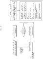
- FIG. 4 is a flowchart showing adjustment of a radar signal to reduce an interference signal, extracted from a cumulative histogram, from a sampled digital input signal in the present disclosure.
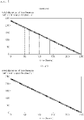
- FIG. 5 is a graph showing disappearance of a target loss caused by malfunction and non-operation due to creation of a wrong target.
- FIG. 1 illustrates a system for processing a radar signal, according to an embodiment of the present disclosure.
- a system for processing a radar signal for deriving a Doppler frequency from a sampled digital input signal radiated by a frequency modulation continuous wave (FMCW) radar may include a processor and an associated non-transitory memory storing software instructions which, when executed by the processor, provides the functionalities of a transmission module that repeatedly transmits a radar signal having a unique frequency variation and a pulse repetition interval, a variation module that varies the frequency variation or pulse repetition interval of the radar signal transmitted by the transmission module, an extraction module that, upon occurrence of interference between the radar signal having the varied frequency variation or pulse repetition interval and another radar signal, extracts an interference signal from the varied radar signal, and an adjustment module that adjusts the radar signal to reduce the extracted interference signal.
- the processor may take the form of one or more processor(s) and associated memory storing program instructions.
- the present disclosure reduces an interference signal of a vehicle-to-vehicle radar signal to mitigate a performance degradation factor in a vehicle using an FMCW radar capable of detecting a distance and a speed of an object by radiating a frequency modulation radar signal, thereby preventing malfunction and non-operation caused by creation of a wrong target, occurring at a main instant when control over the vehicle, such as braking, steering, etc., is performed, and thus providing a normal operation.
- the interference signal may be extracted from the varied radar signal and the radar signal may be adjusted to reduce the extracted interference signal.
- the system for processing a radar signal may generally use a FMCW radar capable of detecting a distance and a speed of an object by radiating a frequency modulation radar signal.
- the FMCW radar may determine a distance between an object and a radar by performing first fast Fourier transform from a sampled digital input signal input through analog-to-digital converter (ADC) data, to detect a distance and a speed of the object.
- a radar signal processing device of a conventional FMCW radar may determine a speed between the object and the radar by performing second fast Fourier transform on a result of first fast Fourier transform stored for each pulse period of the radar signal to derive a Doppler frequency.
- the FMCW radar installed in a conventional vehicle to detect another vehicle and an object is a sensor that radiates an electromagnetic wave and recognizes the object using characteristics of a received electromagnetic wave signal, and undergoes performance degradation thereof due to distortion of a target original signal in an interference phenomenon where a signal of another radar is introduced, such that it is necessary to prevent non-detection where a target disappears or false detection where a wrong target is created.
- the present disclosure reduces an interference signal of a vehicle-to-vehicle radar signal to mitigate a performance degradation factor, thereby preventing malfunction and non-operation caused by creation of a wrong target, occurring at a main instant when control over the vehicle, such as braking, steering, etc., is performed, and thus making a normal operation possible.
- the transmission module may repeatedly transmit a radar signal having a unique frequency variation and a pulse repetition interval.
- the transmission module may radiate a radar signal through an FMCW radar in a vehicle, in which the radar signal may repeatedly transmit a chirp for every FMCW radars between vehicles and a group of repeatedly transmitted chirps may be defined as one frame.
- the radar signal may have a unique value with a different frequency variation and a different pulse repetition interval, and a type of mutual interference between radars may be classified according to a frequency variation and a pulse repetition interval of a radar signal radiated.
- the variation module may vary the frequency variation or the pulse repetition interval of the radar signal transmitted from the transmission module. Even when each radar signal has a unique value with a different frequency variation and a different pulse repetition interval, in the case of occurrence of interference in a radar signal with the same frequency variation and pulse repetition interval between vehicles, a radar blind phenomenon occurs as total interference where a target is not detected at all. Therefore, the radar blind phenomenon where a target is not detected at all may not occur as total interference only when the variation module varies the frequency variation or the pulse repetition interval of the radar signal transmitted by the transmission module. When the frequency variation or the pulse repetition interval is varied, malfunction and non-operation, rather than total interference, may occur instantaneously.
- the extraction module may extract an interference signal from the varied radar signal.
- the frequency variation or the pulse repetition interval of the radar signal may be varied, a cumulative histogram may be calculated for a sampled digital input signal upon occurrence of corresponding instantaneous interference, and the interference signal may be extracted from the calculated cumulative histogram.
- the extraction module may select a threshold from the calculated cumulative histogram, define a signal exceeding the selected threshold as an interference signal, and extract the interference signal.
- the variation module and the extraction module may be located in substantially the same position, and may vary the frequency variation or the pulse repetition interval of the radar signal transmitted by the transmission module or extract the interference signal from the varied radar signal.
- the adjustment module may adjust the radar signal to reduce the extracted interference signal.
- the radar signal may be adjusted to reduce the interference signal by replacing the interference signal with 0, which may be achieved by forming an internal algorithm in the FMCW radar to replace a digital input signal corresponding to the interference signal with 0.
- FIG. 2 is a graph showing interference when frequency variations of two radar signals are different from each other and when the frequency variations of the radar signals are the same as each other.
- FIG. 3 is a graph showing interference corresponding to a pulse repetition interval when frequency variations of two radar signals are the same as each other.
- the variation module may continuously vary the frequency variation or the pulse repetition interval, and the extraction module may extract the interference signal when the variation module varies the radar signal.
- interference may occur between the radar signals instantaneously, increasing the entire noise
- a radar blind phenomenon occurs as total interference in which a target is not detected at all, failing to detect the target at all.
- FIG. 3 for the radar signals with the same frequency variation, but different pulse repetition intervals as shown in a lower side of FIG. 3 , instantaneous interference occurs only in a particular chirp, but for the radar signals with the same frequency variation and the same pulse repetition interval as shown in an upper side of FIG. 3 , the radar blind phenomenon occurs as total interference where a target is not detected at all, failing to detect the target at all.
- the variation module needs to vary the frequency variation or the pulse repetition interval continuously, i.e., at random.
- the extraction module may extract the interference signal from the radar signal varied by the variation module.
- the extraction module may calculate a cumulative histogram for a sampled digital input signal and extract the interference signal from the calculated cumulative histogram.
- the histogram divides a range where measurement values exist into several sections, and the cumulative histogram accumulates all measurement values obtained up to a specific section and divides a range where the measurement values exist into several sections.
- the extraction module may calculate the cumulative histogram for the sampled digital input signal, and the extraction of the interference signal from the calculated cumulative histogram may be performed by first selecting a threshold to be described below and taking a signal exceeding the threshold as the interference signal.
- the cumulative histogram may be calculated by taking an absolute value of the sampled digital input signal, accumulating the absolute value, and then generating and accumulating a profile of an entire digital input signal by comparing an accumulated square value with a reference value.
- the cumulative histogram may be extracted for the sampled digital input signal, and the calculation of the cumulative histogram may be performed by taking an absolute value of the sampled digital input signal and then counting the number of hits between boundary values.
- the total number of boundary values is 64, and the boundary values have a 16 th power range of 0 - 2, such that a histogram may be calculated by counting the number of hits between the boundary values for the sampled digital input signal.
- the cumulative histogram may be calculated by generating and accumulating a profile of an entire digital input signal by comparing an accumulated square value with a reference value.
- the extraction module may select a threshold to be described below through the cumulative histogram, thus extracting the interference signal.
- FIG. 4 is a flowchart showing adjustment of a radar signal to reduce an interference signal, extracted from a cumulative histogram, from a sampled digital input signal in the present disclosure.
- the extraction module may select a threshold from the calculated cumulative histogram, and extract the interference signal for a signal exceeding the selected threshold.
- the threshold may be selected to prevent the sampled digital input signal from diverging or converging to zero (0), and may be selected empirically through multiple test data.
- the extraction module may select the threshold based on a particular rate at which the frequency variation and the pulse repetition interval affect the calculated cumulative histogram, and it can be seen from FIG. 4 that the threshold is selected based on a value 60% of the cumulative histogram through multiple test data.
- the particular rate may be selected based on a rate at which instantaneous interference has a little influence.
- the related art determines a speed between an object and a radar by deriving a Doppler frequency based on first-order fast Fourier transform and second-order fast Fourier transform, instead of selecting the threshold from the cumulative histogram.
- the present disclosure selects the threshold for the sampled digital input signal after extracting the cumulative histogram from the sampled digital input signal.
- the extraction module may select the threshold by calculating a value corresponding to a particular rate in the form of a power series from the cumulative histogram where the sampled digital input signal is calculated.
- the power series may mean a series that may be expressed as ⁇ a(x-a), and may also mean a constant series.
- the extraction module may define a rate at which instantaneous interference has a little influence as the particular rate to select the threshold.
- a random coefficient may be added to an exponential series, in which a value may differ with a value x and a convergence or divergence state may also vary.
- the cumulative histogram may be calculated by taking and accumulating an absolute value of the sampled digital input signal, and then generating and accumulating a profile of an entire digital input signal by comparing an accumulated square value with a reference value, such that the threshold may be selected through a power series for a value corresponding to the particular rate in the cumulative histogram from which the sampled digital input signal is calculated.
- FIG. 5 is a graph showing disappearance of a target loss caused by malfunction and non-operation due to creation of a wrong target.
- the adjustment module may adjust a radar signal to reduce the interference signal by replacing the extracted interference signal with 0.
- the radar signal exceeding the threshold is determined as the interference signal, such that the adjustment module may replace the sampled digital input signal corresponding to the interference signal with 0.
- the interference may disappear when the adjustment module replaces the sampled digital input signal corresponding to the interference signal with 0.
- an X axis indicates time
- a Y axis indicates a detected distance
- a point at which X is 0 may mean a point in time when a target is initially recognized
- a distance detected at this point may be an initially recognized distance.
- the variation module may vary the frequency variation or the pulse repetition interval, and the adjustment module may reduce the interference signal of the radar signal to reduce the interference signal by replacing the interference signal with 0 for the extracted interference signal, thereby mitigating a performance degradation factor and thus preventing malfunction and non-operation caused by creation of a wrong target, occurring at a main instant when control over the vehicle, such as braking, steering, etc., is performed, thus enabling a normal operation.
- a method for processing a radar signal for deriving a Doppler frequency from a sampled digital input signal radiated from a frequency modulation continuous wave (FMCW) radar may include repeatedly transmitting, by a transmission module, a radar signal having a unique frequency variation and a pulse repetition interval, varying, by a variation module, the frequency variation or the pulse repetition interval of the radar signal transmitted from the transmission module, extracting, by an extraction module, an interference signal, upon occurrence of interference between the radar signal having the varied frequency variation or pulse repetition interval and another radar signal, and adjusting, by an adjustment module, the radar signal to reduce the extracted interference signal.
- FMCW frequency modulation continuous wave
- the varying, by the variation module, of the frequency variation or the pulse repetition interval of the radar signal may include continuously varying the frequency variation or the pulse repetition interval, and extracting, by the extraction module, the interference signal when the variation module varies the radar signal.
- the extracting, by the extraction module, of the interference signal, upon occurrence of interference between the radar signal having the varied frequency variation or pulse repetition interval and another radar signal may include calculating a cumulative histogram for a sampled digital input signal and extracting the interference signal from the calculated cumulative histogram.
- the calculating, by the extraction module, of the cumulative histogram for the sampled digital input signal and the extracting of the interference signal from the calculated cumulative histogram may include calculating the cumulative histogram by taking an absolute value of the sampled digital input signal, accumulating the absolute value, and then generating and accumulating a profile of an entire digital input signal by comparing an accumulated square value with a reference value.
- the calculating, by the extraction module, of the cumulative histogram for the sampled digital input signal and extracting the interference signal from the calculated cumulative histogram may include selecting a threshold in the calculated cumulative histogram and extracting the interference signal for a signal exceeding the selected threshold.
- the selecting, by the extraction module, of the threshold from the calculated cumulative histogram and the extracting of the interference signal for the signal exceeding the selected threshold may include selecting the threshold by calculating a value corresponding to a particular rate in the form of a power series from the cumulative histogram where the sampled digital input signal is calculated.
- the adjusting, by the adjustment module, of the radar signal to reduce the extracted interference signal may include adjusting the radar signal to reduce the interference signal by replacing the extracted interference signal with 0.
Landscapes
- Engineering & Computer Science (AREA)
- Radar, Positioning & Navigation (AREA)
- Remote Sensing (AREA)
- Physics & Mathematics (AREA)
- Computer Networks & Wireless Communication (AREA)
- General Physics & Mathematics (AREA)
- Electromagnetism (AREA)
- Signal Processing (AREA)
- Radar Systems Or Details Thereof (AREA)
Abstract
Description
- The present disclosure relates to a signal processing system and method of a radar, and more particularly, to a system and method for processing a radar signal to reduce an interference signal of a vehicle-to-vehicle radar signal in a vehicle using a frequency modulation continuous wave (FMCW) radar capable of detecting a distance and a speed of an object by radiating a frequency modulation radar signal.
- A frequency modulation continuous wave (FMCW) radar may transmit a linear frequency modulation radar signal to receive the transmitted radar signal reflected from an object to be detected, and detect a distance and a speed of the object based on a frequency difference between the received signal and the transmitted signal.
- Vehicles to which radars increasingly used for vehicle driving safety to provide information by recognizing a surrounding environment are applied have increased recently. Among the radars for providing information by recognizing the surrounding environment, a radar of an FMCW scheme is generally applied to a vehicle. When another vehicle and an object are detected by using the radar of the FMCW scheme, mutual interference occurs, causing non-detection where a target disappears or false detection where a wrong target is created.
- The FMCW radar installed in a conventional vehicle to detect another vehicle and an object is a sensor that radiates an electromagnetic wave and recognizes the object using characteristics of a received electromagnetic wave signal, and undergoes degradation in performance thereof due to distortion of a target original signal in an interference phenomenon where a signal of another radar is introduced.
- The matters described as the background art are merely for improving the understanding of the background of the present disclosure, and should not be accepted as acknowledging that they correspond to the prior art known to those of ordinary skill in the art.
- The present disclosure is proposed to solve these problems and aims to reduce an interference signal of a vehicle-to-vehicle radar signal to mitigate a performance degradation factor in a vehicle using an FMCW radar capable of detecting a distance and a speed of an object by radiating a frequency modulation radar signal, thereby preventing malfunction and non-operation caused by creation of a wrong target, occurring at a main instant when control over the vehicle, such as braking, steering, etc., is performed, and thus providing a normal operation.
- According to an aspect of the present disclosure, there is provided a system for processing a radar signal for deriving a Doppler frequency from a sampled digital input signal radiated by a frequency modulation continuous wave (FMCW) radar, the system including a transmission module that repeatedly transmits a radar signal having a unique frequency variation and a pulse repetition interval, a variation module that varies the frequency variation or pulse repetition interval of the radar signal transmitted by the transmission module, an extraction module that, upon occurrence of interference between a varied radar signal having the varied frequency variation or pulse repetition interval and another radar signal, extracts an interference signal from the varied radar signal, and an adjustment module that adjusts the radar signal to reduce the extracted interference signal.
- The variation module may continuously vary the frequency variation or the pulse repetition interval, and the extraction module may extract the interference signal when the variation module varies the radar signal.
- The extraction module may calculate a cumulative histogram for a sampled digital input signal and extract the interference signal from the calculated cumulative histogram.
- The cumulative histogram may be calculated by taking an absolute value of the sampled digital input signal, accumulating the absolute value, and then generating and accumulating a profile of an entire digital input signal by comparing an accumulated square value with a reference value.
- The extraction module may select a threshold from the calculated cumulative histogram, and extract the interference signal for a signal exceeding the selected threshold.
- The extraction module may select the threshold by calculating a value corresponding to a particular rate in the form of a power series from the cumulative histogram where the sampled digital input signal is calculated.
- The adjustment module may adjust a radar signal to reduce the interference signal by replacing the extracted interference signal with 0.
- According to another aspect of the present disclosure, there is provided a method for processing a radar signal for deriving a Doppler frequency from a sampled digital input signal radiated from a frequency modulation continuous wave (FMCW) radar, the method including repeatedly transmitting, by a transmission module, a radar signal having a unique frequency variation and a pulse repetition interval, varying, by a variation module, the frequency variation or the pulse repetition interval of the radar signal transmitted from the transmission module, extracting, by an extraction module, an interference signal, upon occurrence of interference between the radar signal having the varied frequency variation or pulse repetition interval and another radar signal, and adjusting, by an adjustment module, the radar signal to reduce the extracted interference signal.
- The varying, by the variation module, of the frequency variation or the pulse repetition interval of the radar signal may include continuously varying the frequency variation or the pulse repetition interval, and extracting, by the extraction module, the interference signal when the variation module varies the radar signal.
- The extracting, by the extraction module, of the interference signal, upon occurrence of interference between the radar signal having the varied frequency variation or pulse repetition interval and another radar signal may include calculating a cumulative histogram for a sampled digital input signal and extracting the interference signal from the calculated cumulative histogram.
- The calculating, by the extraction module, of the cumulative histogram for the sampled digital input signal and the extracting of the interference signal from the calculated cumulative histogram may include calculating the cumulative histogram by taking an absolute value of the sampled digital input signal, accumulating the absolute value, and then generating and accumulating a profile of an entire digital input signal by comparing an accumulated square value with a reference value.
- The calculating, by the extraction module, of the cumulative histogram for the sampled digital input signal and extracting the interference signal from the calculated cumulative histogram may include selecting a threshold in the calculated cumulative histogram and extracting the interference signal for a signal exceeding the selected threshold.
- The selecting, by the extraction module, of the threshold from the calculated cumulative histogram and the extracting of the interference signal for the signal exceeding the selected threshold may include selecting the threshold by calculating a value corresponding to a particular rate in the form of a power series from the cumulative histogram where the sampled digital input signal is calculated.
- The adjusting, by the adjustment module, of the radar signal to reduce the extracted interference signal may include adjusting the radar signal to reduce the interference signal by replacing the extracted interference signal with 0.
- The system and method for processing a radar signal according to the present disclosure may reduce an interference signal of a vehicle-to-vehicle radar signal to mitigate a performance degradation factor in a vehicle using an FMCW radar capable of detecting a distance and a speed of an object by radiating a frequency modulation radar signal, thereby preventing malfunction and non-operation caused by creation of a wrong target, occurring at a main instant when control over the vehicle, such as braking, steering, etc., is performed, and thus providing a normal operation.
- In addition, effects obtainable in the present disclosure are not limited to the effects as described above, and other effects not described above will become apparent to those of ordinary skill in the art from the following detailed description.
-
-
FIG. 1 illustrates a system for processing a radar signal, according to an embodiment of the present disclosure; -
FIG. 2 is a graph showing interference when frequency variations of two radar signals are different from each other and when the frequency variations of the radar signals are the same as each other; -
FIG. 3 is a graph showing interference corresponding to a pulse repetition interval when frequency variations of two radar signals are the same as each other; -
FIG. 4 is a flowchart showing adjustment of a radar signal to reduce an interference signal, extracted from a cumulative histogram, from a sampled digital input signal in the present disclosure; and -
FIG. 5 is a graph showing disappearance of a target loss caused by malfunction and non-operation due to creation of a wrong target. - For embodiments of the present disclosure disclosed in the present specification or application, specific structural or functional descriptions are only exemplified for the purpose of describing the embodiments of the present disclosure, and the embodiments of the present disclosure may be implemented in various forms, and should not be construed as being limited to the embodiments described in the present specification or application. Hereinafter, an embodiment of the present disclosure will be described in detail with reference to the attached drawings.
-
FIG. 1 illustrates a system for processing a radar signal, according to an embodiment of the present disclosure.FIG. 2 is a graph showing interference when frequency variations of two radar signals are different from each other and when the frequency variations of the radar signals are the same as each other.FIG. 3 is a graph showing interference corresponding to a pulse repetition interval when frequency variations of two radar signals are the same as each other.FIG. 4 is a flowchart showing adjustment of a radar signal to reduce an interference signal, extracted from a cumulative histogram, from a sampled digital input signal in the present disclosure.FIG. 5 is a graph showing disappearance of a target loss caused by malfunction and non-operation due to creation of a wrong target. -
FIG. 1 illustrates a system for processing a radar signal, according to an embodiment of the present disclosure. Referring toFIG. 1 , a system for processing a radar signal for deriving a Doppler frequency from a sampled digital input signal radiated by a frequency modulation continuous wave (FMCW) radar may include a processor and an associated non-transitory memory storing software instructions which, when executed by the processor, provides the functionalities of a transmission module that repeatedly transmits a radar signal having a unique frequency variation and a pulse repetition interval, a variation module that varies the frequency variation or pulse repetition interval of the radar signal transmitted by the transmission module, an extraction module that, upon occurrence of interference between the radar signal having the varied frequency variation or pulse repetition interval and another radar signal, extracts an interference signal from the varied radar signal, and an adjustment module that adjusts the radar signal to reduce the extracted interference signal. The processor may take the form of one or more processor(s) and associated memory storing program instructions. - The present disclosure reduces an interference signal of a vehicle-to-vehicle radar signal to mitigate a performance degradation factor in a vehicle using an FMCW radar capable of detecting a distance and a speed of an object by radiating a frequency modulation radar signal, thereby preventing malfunction and non-operation caused by creation of a wrong target, occurring at a main instant when control over the vehicle, such as braking, steering, etc., is performed, and thus providing a normal operation. To this end, upon occurrence of interference between the radar signal having the varied frequency variation or pulse repetition interval and another radar signal, the interference signal may be extracted from the varied radar signal and the radar signal may be adjusted to reduce the extracted interference signal.
- The system for processing a radar signal may generally use a FMCW radar capable of detecting a distance and a speed of an object by radiating a frequency modulation radar signal. The FMCW radar may determine a distance between an object and a radar by performing first fast Fourier transform from a sampled digital input signal input through analog-to-digital converter (ADC) data, to detect a distance and a speed of the object. A radar signal processing device of a conventional FMCW radar may determine a speed between the object and the radar by performing second fast Fourier transform on a result of first fast Fourier transform stored for each pulse period of the radar signal to derive a Doppler frequency. When the system for processing a radar signal detects another vehicle and an object by using the radar of the FMCW scheme, mutual interference occurs, causing non-detection where a target disappears or false detection where a wrong target is created. The FMCW radar installed in a conventional vehicle to detect another vehicle and an object is a sensor that radiates an electromagnetic wave and recognizes the object using characteristics of a received electromagnetic wave signal, and undergoes performance degradation thereof due to distortion of a target original signal in an interference phenomenon where a signal of another radar is introduced, such that it is necessary to prevent non-detection where a target disappears or false detection where a wrong target is created.
- Therefore, the present disclosure reduces an interference signal of a vehicle-to-vehicle radar signal to mitigate a performance degradation factor, thereby preventing malfunction and non-operation caused by creation of a wrong target, occurring at a main instant when control over the vehicle, such as braking, steering, etc., is performed, and thus making a normal operation possible.
- More specifically, the transmission module may repeatedly transmit a radar signal having a unique frequency variation and a pulse repetition interval. The transmission module may radiate a radar signal through an FMCW radar in a vehicle, in which the radar signal may repeatedly transmit a chirp for every FMCW radars between vehicles and a group of repeatedly transmitted chirps may be defined as one frame. The radar signal may have a unique value with a different frequency variation and a different pulse repetition interval, and a type of mutual interference between radars may be classified according to a frequency variation and a pulse repetition interval of a radar signal radiated.
- The variation module may vary the frequency variation or the pulse repetition interval of the radar signal transmitted from the transmission module. Even when each radar signal has a unique value with a different frequency variation and a different pulse repetition interval, in the case of occurrence of interference in a radar signal with the same frequency variation and pulse repetition interval between vehicles, a radar blind phenomenon occurs as total interference where a target is not detected at all. Therefore, the radar blind phenomenon where a target is not detected at all may not occur as total interference only when the variation module varies the frequency variation or the pulse repetition interval of the radar signal transmitted by the transmission module. When the frequency variation or the pulse repetition interval is varied, malfunction and non-operation, rather than total interference, may occur instantaneously. In the case of instantaneous interference, a large signal compared to a normal signal comes in a time domain, such that when first-order fast Fourier transform and second-order fast Fourier transform are performed, entire noise may be increased, degrading the detection performance of the FMCW radar and even causing non-detection. Upon occurrence of interference between the radar signal having the varied frequency variation or pulse repetition interval and another radar signal, the extraction module may extract an interference signal from the varied radar signal. In the present disclosure, the frequency variation or the pulse repetition interval of the radar signal may be varied, a cumulative histogram may be calculated for a sampled digital input signal upon occurrence of corresponding instantaneous interference, and the interference signal may be extracted from the calculated cumulative histogram. The extraction module may select a threshold from the calculated cumulative histogram, define a signal exceeding the selected threshold as an interference signal, and extract the interference signal. The variation module and the extraction module may be located in substantially the same position, and may vary the frequency variation or the pulse repetition interval of the radar signal transmitted by the transmission module or extract the interference signal from the varied radar signal. The adjustment module may adjust the radar signal to reduce the extracted interference signal. The radar signal may be adjusted to reduce the interference signal by replacing the interference signal with 0, which may be achieved by forming an internal algorithm in the FMCW radar to replace a digital input signal corresponding to the interference signal with 0.
-
FIG. 2 is a graph showing interference when frequency variations of two radar signals are different from each other and when the frequency variations of the radar signals are the same as each other.FIG. 3 is a graph showing interference corresponding to a pulse repetition interval when frequency variations of two radar signals are the same as each other. - The variation module may continuously vary the frequency variation or the pulse repetition interval, and the extraction module may extract the interference signal when the variation module varies the radar signal.
- Referring to
FIG. 2 , for radar signals with the same pulse repetition interval, but different frequency variations, interference may occur between the radar signals instantaneously, increasing the entire noise, and for the radar signals with the same pulse repetition interval, but different frequency variations, a radar blind phenomenon occurs as total interference in which a target is not detected at all, failing to detect the target at all. Referring toFIG. 3 , for the radar signals with the same frequency variation, but different pulse repetition intervals as shown in a lower side ofFIG. 3 , instantaneous interference occurs only in a particular chirp, but for the radar signals with the same frequency variation and the same pulse repetition interval as shown in an upper side ofFIG. 3 , the radar blind phenomenon occurs as total interference where a target is not detected at all, failing to detect the target at all. As a result, to prevent total interference where a target of a radar signal with a unique frequency variation and a pulse repetition interval is not detected at all, the variation module needs to vary the frequency variation or the pulse repetition interval continuously, i.e., at random. Thus, the extraction module may extract the interference signal from the radar signal varied by the variation module. - The extraction module may calculate a cumulative histogram for a sampled digital input signal and extract the interference signal from the calculated cumulative histogram.
- The histogram divides a range where measurement values exist into several sections, and the cumulative histogram accumulates all measurement values obtained up to a specific section and divides a range where the measurement values exist into several sections. The extraction module may calculate the cumulative histogram for the sampled digital input signal, and the extraction of the interference signal from the calculated cumulative histogram may be performed by first selecting a threshold to be described below and taking a signal exceeding the threshold as the interference signal.
- The cumulative histogram may be calculated by taking an absolute value of the sampled digital input signal, accumulating the absolute value, and then generating and accumulating a profile of an entire digital input signal by comparing an accumulated square value with a reference value.
- The cumulative histogram may be extracted for the sampled digital input signal, and the calculation of the cumulative histogram may be performed by taking an absolute value of the sampled digital input signal and then counting the number of hits between boundary values. The total number of boundary values is 64, and the boundary values have a 16th power range of 0 - 2, such that a histogram may be calculated by counting the number of hits between the boundary values for the sampled digital input signal. The cumulative histogram may be calculated by generating and accumulating a profile of an entire digital input signal by comparing an accumulated square value with a reference value. The extraction module may select a threshold to be described below through the cumulative histogram, thus extracting the interference signal.
-
FIG. 4 is a flowchart showing adjustment of a radar signal to reduce an interference signal, extracted from a cumulative histogram, from a sampled digital input signal in the present disclosure. - Referring to
FIG. 4 , the extraction module may select a threshold from the calculated cumulative histogram, and extract the interference signal for a signal exceeding the selected threshold. - The threshold may be selected to prevent the sampled digital input signal from diverging or converging to zero (0), and may be selected empirically through multiple test data. The extraction module may select the threshold based on a particular rate at which the frequency variation and the pulse repetition interval affect the calculated cumulative histogram, and it can be seen from
FIG. 4 that the threshold is selected based on avalue 60% of the cumulative histogram through multiple test data. The particular rate may be selected based on a rate at which instantaneous interference has a little influence. The related art determines a speed between an object and a radar by deriving a Doppler frequency based on first-order fast Fourier transform and second-order fast Fourier transform, instead of selecting the threshold from the cumulative histogram. However, the present disclosure selects the threshold for the sampled digital input signal after extracting the cumulative histogram from the sampled digital input signal. - The extraction module may select the threshold by calculating a value corresponding to a particular rate in the form of a power series from the cumulative histogram where the sampled digital input signal is calculated.
- The power series may mean a series that may be expressed as ∑a(x-a), and may also mean a constant series. The extraction module may define a rate at which instantaneous interference has a little influence as the particular rate to select the threshold. For the power series, a random coefficient may be added to an exponential series, in which a value may differ with a value x and a convergence or divergence state may also vary. Therefore, the cumulative histogram may be calculated by taking and accumulating an absolute value of the sampled digital input signal, and then generating and accumulating a profile of an entire digital input signal by comparing an accumulated square value with a reference value, such that the threshold may be selected through a power series for a value corresponding to the particular rate in the cumulative histogram from which the sampled digital input signal is calculated.
-
FIG. 5 is a graph showing disappearance of a target loss caused by malfunction and non-operation due to creation of a wrong target. - The adjustment module may adjust a radar signal to reduce the interference signal by replacing the extracted interference signal with 0.
- The radar signal exceeding the threshold is determined as the interference signal, such that the adjustment module may replace the sampled digital input signal corresponding to the interference signal with 0. Although instantaneous interference occurs in the radar signal with the frequency variation or pulse repetition interval varied by the variation module, the interference may disappear when the adjustment module replaces the sampled digital input signal corresponding to the interference signal with 0. Referring to
FIG. 5 , an X axis indicates time, a Y axis indicates a detected distance, a point at which X is 0 may mean a point in time when a target is initially recognized, and a distance detected at this point may be an initially recognized distance. Left graphs ofFIG. 5 show interference when a distance and a speed of the object from the FMCW radar are generally detected, in which a discontinuous point indicates non-detection or false detection. As can be seen from right graphs ofFIG. 5 , the variation module may vary the frequency variation or the pulse repetition interval, and the adjustment module may reduce the interference signal of the radar signal to reduce the interference signal by replacing the interference signal with 0 for the extracted interference signal, thereby mitigating a performance degradation factor and thus preventing malfunction and non-operation caused by creation of a wrong target, occurring at a main instant when control over the vehicle, such as braking, steering, etc., is performed, thus enabling a normal operation. - A method for processing a radar signal for deriving a Doppler frequency from a sampled digital input signal radiated from a frequency modulation continuous wave (FMCW) radar may include repeatedly transmitting, by a transmission module, a radar signal having a unique frequency variation and a pulse repetition interval, varying, by a variation module, the frequency variation or the pulse repetition interval of the radar signal transmitted from the transmission module, extracting, by an extraction module, an interference signal, upon occurrence of interference between the radar signal having the varied frequency variation or pulse repetition interval and another radar signal, and adjusting, by an adjustment module, the radar signal to reduce the extracted interference signal.
- In addition, the varying, by the variation module, of the frequency variation or the pulse repetition interval of the radar signal may include continuously varying the frequency variation or the pulse repetition interval, and extracting, by the extraction module, the interference signal when the variation module varies the radar signal.
- The extracting, by the extraction module, of the interference signal, upon occurrence of interference between the radar signal having the varied frequency variation or pulse repetition interval and another radar signal may include calculating a cumulative histogram for a sampled digital input signal and extracting the interference signal from the calculated cumulative histogram.
- The calculating, by the extraction module, of the cumulative histogram for the sampled digital input signal and the extracting of the interference signal from the calculated cumulative histogram may include calculating the cumulative histogram by taking an absolute value of the sampled digital input signal, accumulating the absolute value, and then generating and accumulating a profile of an entire digital input signal by comparing an accumulated square value with a reference value.
- The calculating, by the extraction module, of the cumulative histogram for the sampled digital input signal and extracting the interference signal from the calculated cumulative histogram may include selecting a threshold in the calculated cumulative histogram and extracting the interference signal for a signal exceeding the selected threshold.
- The selecting, by the extraction module, of the threshold from the calculated cumulative histogram and the extracting of the interference signal for the signal exceeding the selected threshold may include selecting the threshold by calculating a value corresponding to a particular rate in the form of a power series from the cumulative histogram where the sampled digital input signal is calculated.
- The adjusting, by the adjustment module, of the radar signal to reduce the extracted interference signal may include adjusting the radar signal to reduce the interference signal by replacing the extracted interference signal with 0.
- As described above, although the present disclosure has been shown and described in relation to specific embodiments thereof, it would be obvious to those of ordinary skill in the art that the present disclosure can be variously improved and changed without departing from the spirit of the present disclosure provided by the following claims.
DESCRIPTION OF REFERENCE NUMERALS A: transmission module B: variation module C: extraction module D: adjustment module
Claims (14)
- A system for processing a radar signal for deriving a Doppler frequency from a sampled digital input signal radiated from a frequency modulation continuous wave (FMCW) radar, the system comprising:a transmission module repeatedly transmitting a radar signal having a unique frequency variation and a pulse repetition interval;a variation module varying the frequency variation or the pulse repetition interval of the radar signal transmitted from the transmission module;an extraction module extracting an interference signal from the varied radar signal upon occurrence of interference between the radar signal having the varied frequency variation or pulse repetition interval and another radar signal; andan adjustment module adjusting the radar signal to reduce the extracted interference signal.
- The system of claim 1, wherein the variation module continuously varies the frequency variation or the pulse repetition interval, and the extraction module extracts the interference signal when the variation module varies the radar signal.
- The system of claim 1, wherein the extraction module calculates a cumulative histogram for a sampled digital input signal and extracts the interference signal from the calculated cumulative histogram.
- The system of claim 3, wherein the cumulative histogram is calculated by taking an absolute value of the sampled digital input signal, accumulating the absolute value, and then generating and accumulating a profile of an entire digital input signal by comparing an accumulated square value with a reference value.
- The system of claim 3, wherein the extraction module selects a threshold in the calculated cumulative histogram and extracts the interference signal for a signal exceeding the selected threshold.
- The system of claim 5, wherein the extraction module selects the threshold by calculating a value corresponding to a particular rate in the form of a power series from the cumulative histogram where the sampled digital input signal is calculated.
- The system of claim 1, wherein the adjustment module adjusts the radar signal to reduce the interference signal by replacing the extracted interference signal with 0.
- A method for processing a radar signal for deriving a Doppler frequency from a sampled digital input signal radiated from a frequency modulation continuous wave (FMCW) radar, the method comprising:repeatedly transmitting, by a transmission module, a radar signal having a unique frequency variation and a pulse repetition interval;varying, by a variation module, the frequency variation or the pulse repetition interval of the radar signal transmitted from the transmission module;extracting, by an extraction module, an interference signal, upon occurrence of interference between the radar signal having the varied frequency variation or pulse repetition interval and another radar signal; andadjusting, by an adjustment module, the radar signal to reduce the extracted interference signal.
- The method of claim 8, wherein the varying, by the variation module, of the frequency variation or the pulse repetition interval of the radar signal comprises continuously varying the frequency variation or the pulse repetition interval, and extracting, by the extraction module, the interference signal when the variation module varies the radar signal.
- The method of claim 8, wherein the extracting, by the extraction module, of the interference signal, upon occurrence of interference between the radar signal having the varied frequency variation or pulse repetition interval and another radar signal comprises calculating a cumulative histogram for a sampled digital input signal and extracting the interference signal from the calculated cumulative histogram.
- The method of claim 10, wherein the calculating, by the extraction module, of the cumulative histogram for the sampled digital input signal and the extracting of the interference signal from the calculated cumulative histogram comprises calculating the cumulative histogram by taking an absolute value of the sampled digital input signal, accumulating the absolute value, and then generating and accumulating a profile of an entire digital input signal by comparing an accumulated square value with a reference value.
- The method of claim 10, wherein the calculating, by the extraction module, of the cumulative histogram for the sampled digital input signal and extracting the interference signal from the calculated cumulative histogram comprises selecting a threshold in the calculated cumulative histogram and extracting the interference signal for a signal exceeding the selected threshold.
- The method of claim 12, wherein the selecting, by the extraction module, of the threshold from the calculated cumulative histogram and the extracting of the interference signal for the signal exceeding the selected threshold comprises selecting the threshold by calculating a value corresponding to a particular rate in the form of a power series from the cumulative histogram where the sampled digital input signal is calculated.
- The method of claim 8, wherein the adjusting, by the adjustment module, of the radar signal to reduce the extracted interference signal comprises adjusting the radar signal to reduce the interference signal by replacing the extracted interference signal with 0.
Applications Claiming Priority (1)
| Application Number | Priority Date | Filing Date | Title |
|---|---|---|---|
| KR1020210077457A KR102628228B1 (en) | 2021-06-15 | 2021-06-15 | Radar signal processing system and processing method |
Publications (2)
| Publication Number | Publication Date |
|---|---|
| EP4105677A1 true EP4105677A1 (en) | 2022-12-21 |
| EP4105677B1 EP4105677B1 (en) | 2025-07-23 |
Family
ID=77710550
Family Applications (1)
| Application Number | Title | Priority Date | Filing Date |
|---|---|---|---|
| EP21195808.7A Active EP4105677B1 (en) | 2021-06-15 | 2021-09-09 | System and method for processing radar signal |
Country Status (4)
| Country | Link |
|---|---|
| US (1) | US12135390B2 (en) |
| EP (1) | EP4105677B1 (en) |
| KR (1) | KR102628228B1 (en) |
| CN (1) | CN115480217B (en) |
Families Citing this family (4)
| Publication number | Priority date | Publication date | Assignee | Title |
|---|---|---|---|---|
| CN116660840B (en) * | 2023-06-06 | 2026-05-19 | 青岛九维华盾科技研究院有限公司 | A method for identifying real and fake targets based on joint features in the fast and slow time domains when fake target samples are scarce. |
| CN116718992B (en) * | 2023-06-16 | 2026-07-24 | 中国人民解放军63892部队 | A self-concealed jamming method for pulse Doppler radar |
| CN118191755B (en) * | 2024-05-16 | 2024-07-23 | 珠海正和微芯科技有限公司 | Anti-interference detection method for step frequency radar |
| CN118244231B (en) * | 2024-05-29 | 2024-08-06 | 北京东远润兴科技有限公司 | Radar signal sorting method, device, terminal equipment and storage medium |
Citations (2)
| Publication number | Priority date | Publication date | Assignee | Title |
|---|---|---|---|---|
| US20080231496A1 (en) * | 2007-03-20 | 2008-09-25 | Denso Corporation | Method for determining noise floor level and radar using the same |
| US20200025866A1 (en) * | 2018-07-19 | 2020-01-23 | Qualcomm Incorporated | Multi-radar coexistence using slow rate interference identification and suppression |
Family Cites Families (31)
| Publication number | Priority date | Publication date | Assignee | Title |
|---|---|---|---|---|
| DE4104907C1 (en) * | 1991-02-18 | 1992-08-27 | Dornier Gmbh, 7990 Friedrichshafen, De | |
| US5828333A (en) * | 1997-01-21 | 1998-10-27 | Northrop Grumman Corporation | Multiple access diplex doppler radar |
| DE10059673A1 (en) * | 2000-12-01 | 2002-06-06 | Bosch Gmbh Robert | Pulse radar method as well as pulse radar sensor and system |
| DE10254982A1 (en) * | 2002-11-26 | 2004-06-03 | Robert Bosch Gmbh | Method and device for adaptive power control |
| US20060262007A1 (en) * | 2004-01-16 | 2006-11-23 | Clariant Technologies, Corp. | Methods and apparatus for automotive radar sensors |
| JP5226185B2 (en) * | 2006-02-15 | 2013-07-03 | 富士通株式会社 | Detecting and ranging device |
| JP2007232498A (en) * | 2006-02-28 | 2007-09-13 | Hitachi Ltd | Obstacle detection system |
| US7787569B2 (en) * | 2006-07-26 | 2010-08-31 | Broadcom Corporation | Radio frequency integrated circuit having frequency dependent noise mitigation with spectrum spreading |
| JP2008232832A (en) * | 2007-03-20 | 2008-10-02 | Denso Corp | Interference judgment method, FMCW radar |
| US8022864B2 (en) * | 2007-11-08 | 2011-09-20 | The United States Of America As Represented By The Secretary Of Commerce | Detection of transient signals in doppler spectra |
| JP5430068B2 (en) * | 2008-02-15 | 2014-02-26 | 株式会社ジャパンディスプレイ | Display device |
| US7791528B2 (en) * | 2008-11-24 | 2010-09-07 | Autoliv Asp, Inc. | Method and apparatus for radar signal processing |
| EP2390679B1 (en) * | 2010-05-27 | 2012-10-03 | Mitsubishi Electric R&D Centre Europe B.V. | Automotive radar with radio-frequency interference avoidance |
| KR20120081422A (en) | 2011-01-11 | 2012-07-19 | 삼성전자주식회사 | Terminal having touch screen and method for inputting letter according to touch event thereof |
| WO2013161517A1 (en) * | 2012-04-27 | 2013-10-31 | 古野電気株式会社 | Pulse signal setting device, radar apparatus, pulse signal setting method and pulse signal setting program |
| KR101295061B1 (en) | 2012-07-25 | 2013-08-08 | 국방과학연구소 | Signal processing module of fmcw radar and memory managing method thereof |
| US20200064444A1 (en) * | 2015-07-17 | 2020-02-27 | Origin Wireless, Inc. | Method, apparatus, and system for human identification based on human radio biometric information |
| DE102013210256A1 (en) * | 2013-06-03 | 2014-12-04 | Robert Bosch Gmbh | INTERFERENCE SUPPRESSION ON AN FMCW RADAR |
| KR102364593B1 (en) * | 2015-01-30 | 2022-02-18 | 현대모비스 주식회사 | vehicle radar system |
| SE541162C2 (en) * | 2015-10-20 | 2019-04-23 | Qamcom Tech Ab | Radar system with auxiliary channel and method |
| KR20170068950A (en) * | 2015-12-10 | 2017-06-20 | 김영욱 | Fmcw radar and method for aviding interference of fmcw radar |
| US11002829B2 (en) * | 2016-04-15 | 2021-05-11 | Mediatek Inc. | Radar interference mitigation method and apparatus |
| US10379201B2 (en) * | 2016-10-26 | 2019-08-13 | GM Global Technology Operations LLC | Radar interference mitigation and collaborative operation |
| KR102146156B1 (en) * | 2018-07-04 | 2020-08-19 | 홍익대학교 산학협력단 | Method and apparatus for detecting object |
| DE102018126034A1 (en) * | 2018-10-19 | 2020-04-23 | Infineon Technologies Ag | FMCW RADAR WITH INTERFERENCE CANCELLATION |
| JP7623106B2 (en) * | 2019-05-12 | 2025-01-28 | オリジン リサーチ ワイヤレス, インコーポレイテッド | Method, Apparatus and System for Wireless Tracking, Scanning and Surveillance - Patent application |
| DE102019114551B4 (en) * | 2019-05-29 | 2025-10-30 | Infineon Technologies Ag | DETECTION OF INTERFERENCE-CAUSED DISTURBANCES IN FMCW RADAR SYSTEMS |
| DE102019215191A1 (en) * | 2019-09-09 | 2021-03-11 | Robert Bosch Gmbh | FMCW radar sensor with synchronized high-frequency components |
| US12078748B2 (en) * | 2020-01-13 | 2024-09-03 | Uhnder, Inc. | Method and system for intefrence management for digital radars |
| EP3910367B1 (en) * | 2020-05-11 | 2022-06-29 | Axis AB | Method and device for radar interference reduction |
| US20220349986A1 (en) * | 2021-04-30 | 2022-11-03 | Nxp B.V. | Radar communication with interference suppression |
-
2021
- 2021-06-15 KR KR1020210077457A patent/KR102628228B1/en active Active
- 2021-09-09 EP EP21195808.7A patent/EP4105677B1/en active Active
- 2021-09-16 US US17/476,977 patent/US12135390B2/en active Active
- 2021-09-18 CN CN202111110036.1A patent/CN115480217B/en active Active
Patent Citations (2)
| Publication number | Priority date | Publication date | Assignee | Title |
|---|---|---|---|---|
| US20080231496A1 (en) * | 2007-03-20 | 2008-09-25 | Denso Corporation | Method for determining noise floor level and radar using the same |
| US20200025866A1 (en) * | 2018-07-19 | 2020-01-23 | Qualcomm Incorporated | Multi-radar coexistence using slow rate interference identification and suppression |
Also Published As
| Publication number | Publication date |
|---|---|
| CN115480217A (en) | 2022-12-16 |
| EP4105677B1 (en) | 2025-07-23 |
| KR20220167990A (en) | 2022-12-22 |
| US12135390B2 (en) | 2024-11-05 |
| US20220397641A1 (en) | 2022-12-15 |
| KR102628228B1 (en) | 2024-01-23 |
| CN115480217B (en) | 2025-09-30 |
Similar Documents
| Publication | Publication Date | Title |
|---|---|---|
| EP4105677B1 (en) | System and method for processing radar signal | |
| US10962640B2 (en) | Radar device and control method of radar device | |
| KR101199169B1 (en) | Method and radar apparatus for detecting target object | |
| US10386458B2 (en) | Radar signal processing device and method | |
| US11630183B2 (en) | Method and devices for radar interference reduction | |
| US9612323B2 (en) | Radar apparatus | |
| EP1980873B1 (en) | History or image based methods for altitude determination in a radar altimeter | |
| KR101040315B1 (en) | Target detection device adapting to clutter environment | |
| CN107076845B (en) | Radar sensor | |
| CN104502899A (en) | Self-adaptive constant false alarm rate target detection method | |
| CA2935304A1 (en) | Antenna coupling for sensing and dynamic transmission | |
| JP2009250616A (en) | Radar signal processing device | |
| US12461200B2 (en) | Detection of blocked radar sensor | |
| CN112213695A (en) | Airfield runway foreign matter detection method based on unit average clutter map | |
| CN117930166A (en) | Millimeter wave radar shielding detection method based on multiple radars | |
| CN111521978B (en) | Radar signal target angle detection method, device, computer equipment and medium | |
| US10605893B2 (en) | Radar saturating clutter mitigation by waveform selection | |
| KR101619064B1 (en) | Target tracking method using active clutter map | |
| CN108132460B (en) | Pulse compression compensation algorithm based on frequency domain channel equalization | |
| CN111157954A (en) | Adaptive Adjustment Method of Ground Radar Target Detection Threshold Coefficient | |
| KR102662229B1 (en) | Method for detecting target object and apparatus thereof | |
| KR102329753B1 (en) | Apparatus and method for determining peak effectiveness | |
| KR101843532B1 (en) | Method Processing Chaff Jamming Signal in W-Band Millimeter Wave Seeker | |
| CN111175704A (en) | Generation of orthogonal signal families for Code Division Multiple Access (CDMA) radar systems | |
| JP7271350B2 (en) | Radar device and target detection method |
Legal Events
| Date | Code | Title | Description |
|---|---|---|---|
| PUAI | Public reference made under article 153(3) epc to a published international application that has entered the european phase |
Free format text: ORIGINAL CODE: 0009012 |
|
| STAA | Information on the status of an ep patent application or granted ep patent |
Free format text: STATUS: REQUEST FOR EXAMINATION WAS MADE |
|
| 17P | Request for examination filed |
Effective date: 20210909 |
|
| AK | Designated contracting states |
Kind code of ref document: A1 Designated state(s): AL AT BE BG CH CY CZ DE DK EE ES FI FR GB GR HR HU IE IS IT LI LT LU LV MC MK MT NL NO PL PT RO RS SE SI SK SM TR |
|
| RBV | Designated contracting states (corrected) |
Designated state(s): AL AT BE BG CH CY CZ DE DK EE ES FI FR GB GR HR HU IE IS IT LI LT LU LV MC MK MT NL NO PL PT RO RS SE SI SK SM TR |
|
| STAA | Information on the status of an ep patent application or granted ep patent |
Free format text: STATUS: EXAMINATION IS IN PROGRESS |
|
| 17Q | First examination report despatched |
Effective date: 20230926 |
|
| GRAP | Despatch of communication of intention to grant a patent |
Free format text: ORIGINAL CODE: EPIDOSNIGR1 |
|
| STAA | Information on the status of an ep patent application or granted ep patent |
Free format text: STATUS: GRANT OF PATENT IS INTENDED |
|
| INTG | Intention to grant announced |
Effective date: 20250214 |
|
| P01 | Opt-out of the competence of the unified patent court (upc) registered |
Free format text: CASE NUMBER: APP_13524/2025 Effective date: 20250319 |
|
| GRAS | Grant fee paid |
Free format text: ORIGINAL CODE: EPIDOSNIGR3 |
|
| GRAA | (expected) grant |
Free format text: ORIGINAL CODE: 0009210 |
|
| STAA | Information on the status of an ep patent application or granted ep patent |
Free format text: STATUS: THE PATENT HAS BEEN GRANTED |
|
| AK | Designated contracting states |
Kind code of ref document: B1 Designated state(s): AL AT BE BG CH CY CZ DE DK EE ES FI FR GB GR HR HU IE IS IT LI LT LU LV MC MK MT NL NO PL PT RO RS SE SI SK SM TR |
|
| REG | Reference to a national code |
Ref country code: GB Ref legal event code: FG4D |
|
| REG | Reference to a national code |
Ref country code: CH Ref legal event code: EP |
|
| REG | Reference to a national code |
Ref country code: DE Ref legal event code: R096 Ref document number: 602021034500 Country of ref document: DE |
|
| REG | Reference to a national code |
Ref country code: IE Ref legal event code: FG4D |
|
| PGFP | Annual fee paid to national office [announced via postgrant information from national office to epo] |
Ref country code: DE Payment date: 20250815 Year of fee payment: 5 |
|
| PGFP | Annual fee paid to national office [announced via postgrant information from national office to epo] |
Ref country code: GB Payment date: 20250923 Year of fee payment: 5 |
|
| PGFP | Annual fee paid to national office [announced via postgrant information from national office to epo] |
Ref country code: AT Payment date: 20251020 Year of fee payment: 5 Ref country code: FR Payment date: 20250926 Year of fee payment: 5 |
|
| REG | Reference to a national code |
Ref country code: NL Ref legal event code: MP Effective date: 20250723 |
|
| PG25 | Lapsed in a contracting state [announced via postgrant information from national office to epo] |
Ref country code: PT Free format text: LAPSE BECAUSE OF FAILURE TO SUBMIT A TRANSLATION OF THE DESCRIPTION OR TO PAY THE FEE WITHIN THE PRESCRIBED TIME-LIMIT Effective date: 20251124 |
|
| PG25 | Lapsed in a contracting state [announced via postgrant information from national office to epo] |
Ref country code: NL Free format text: LAPSE BECAUSE OF FAILURE TO SUBMIT A TRANSLATION OF THE DESCRIPTION OR TO PAY THE FEE WITHIN THE PRESCRIBED TIME-LIMIT Effective date: 20250723 |
|
| REG | Reference to a national code |
Ref country code: AT Ref legal event code: MK05 Ref document number: 1816950 Country of ref document: AT Kind code of ref document: T Effective date: 20250723 |
|
| PG25 | Lapsed in a contracting state [announced via postgrant information from national office to epo] |
Ref country code: IS Free format text: LAPSE BECAUSE OF FAILURE TO SUBMIT A TRANSLATION OF THE DESCRIPTION OR TO PAY THE FEE WITHIN THE PRESCRIBED TIME-LIMIT Effective date: 20251123 |
|
| PG25 | Lapsed in a contracting state [announced via postgrant information from national office to epo] |
Ref country code: NO Free format text: LAPSE BECAUSE OF FAILURE TO SUBMIT A TRANSLATION OF THE DESCRIPTION OR TO PAY THE FEE WITHIN THE PRESCRIBED TIME-LIMIT Effective date: 20251023 |
|
| REG | Reference to a national code |
Ref country code: LT Ref legal event code: MG9D |
|
| PG25 | Lapsed in a contracting state [announced via postgrant information from national office to epo] |
Ref country code: AT Free format text: LAPSE BECAUSE OF FAILURE TO SUBMIT A TRANSLATION OF THE DESCRIPTION OR TO PAY THE FEE WITHIN THE PRESCRIBED TIME-LIMIT Effective date: 20250723 |
|
| PG25 | Lapsed in a contracting state [announced via postgrant information from national office to epo] |
Ref country code: FI Free format text: LAPSE BECAUSE OF FAILURE TO SUBMIT A TRANSLATION OF THE DESCRIPTION OR TO PAY THE FEE WITHIN THE PRESCRIBED TIME-LIMIT Effective date: 20250723 |
|
| PG25 | Lapsed in a contracting state [announced via postgrant information from national office to epo] |
Ref country code: HR Free format text: LAPSE BECAUSE OF FAILURE TO SUBMIT A TRANSLATION OF THE DESCRIPTION OR TO PAY THE FEE WITHIN THE PRESCRIBED TIME-LIMIT Effective date: 20250723 |
|
| PG25 | Lapsed in a contracting state [announced via postgrant information from national office to epo] |
Ref country code: GR Free format text: LAPSE BECAUSE OF FAILURE TO SUBMIT A TRANSLATION OF THE DESCRIPTION OR TO PAY THE FEE WITHIN THE PRESCRIBED TIME-LIMIT Effective date: 20251024 |
|
| PG25 | Lapsed in a contracting state [announced via postgrant information from national office to epo] |
Ref country code: SE Free format text: LAPSE BECAUSE OF FAILURE TO SUBMIT A TRANSLATION OF THE DESCRIPTION OR TO PAY THE FEE WITHIN THE PRESCRIBED TIME-LIMIT Effective date: 20250723 |
|
| PG25 | Lapsed in a contracting state [announced via postgrant information from national office to epo] |
Ref country code: LV Free format text: LAPSE BECAUSE OF FAILURE TO SUBMIT A TRANSLATION OF THE DESCRIPTION OR TO PAY THE FEE WITHIN THE PRESCRIBED TIME-LIMIT Effective date: 20250723 |
|
| PG25 | Lapsed in a contracting state [announced via postgrant information from national office to epo] |
Ref country code: BG Free format text: LAPSE BECAUSE OF FAILURE TO SUBMIT A TRANSLATION OF THE DESCRIPTION OR TO PAY THE FEE WITHIN THE PRESCRIBED TIME-LIMIT Effective date: 20250723 Ref country code: PL Free format text: LAPSE BECAUSE OF FAILURE TO SUBMIT A TRANSLATION OF THE DESCRIPTION OR TO PAY THE FEE WITHIN THE PRESCRIBED TIME-LIMIT Effective date: 20250723 |
|
| PG25 | Lapsed in a contracting state [announced via postgrant information from national office to epo] |
Ref country code: RS Free format text: LAPSE BECAUSE OF FAILURE TO SUBMIT A TRANSLATION OF THE DESCRIPTION OR TO PAY THE FEE WITHIN THE PRESCRIBED TIME-LIMIT Effective date: 20251023 |
|
| PG25 | Lapsed in a contracting state [announced via postgrant information from national office to epo] |
Ref country code: ES Free format text: LAPSE BECAUSE OF FAILURE TO SUBMIT A TRANSLATION OF THE DESCRIPTION OR TO PAY THE FEE WITHIN THE PRESCRIBED TIME-LIMIT Effective date: 20250723 |
|
| PG25 | Lapsed in a contracting state [announced via postgrant information from national office to epo] |
Ref country code: RO Free format text: LAPSE BECAUSE OF FAILURE TO SUBMIT A TRANSLATION OF THE DESCRIPTION OR TO PAY THE FEE WITHIN THE PRESCRIBED TIME-LIMIT Effective date: 20250723 |
|
| PG25 | Lapsed in a contracting state [announced via postgrant information from national office to epo] |
Ref country code: SM Free format text: LAPSE BECAUSE OF FAILURE TO SUBMIT A TRANSLATION OF THE DESCRIPTION OR TO PAY THE FEE WITHIN THE PRESCRIBED TIME-LIMIT Effective date: 20250723 |
|
| PG25 | Lapsed in a contracting state [announced via postgrant information from national office to epo] |
Ref country code: DK Free format text: LAPSE BECAUSE OF FAILURE TO SUBMIT A TRANSLATION OF THE DESCRIPTION OR TO PAY THE FEE WITHIN THE PRESCRIBED TIME-LIMIT Effective date: 20250723 |
|
| PG25 | Lapsed in a contracting state [announced via postgrant information from national office to epo] |
Ref country code: IT Free format text: LAPSE BECAUSE OF FAILURE TO SUBMIT A TRANSLATION OF THE DESCRIPTION OR TO PAY THE FEE WITHIN THE PRESCRIBED TIME-LIMIT Effective date: 20250723 |
|
| PG25 | Lapsed in a contracting state [announced via postgrant information from national office to epo] |
Ref country code: CZ Free format text: LAPSE BECAUSE OF FAILURE TO SUBMIT A TRANSLATION OF THE DESCRIPTION OR TO PAY THE FEE WITHIN THE PRESCRIBED TIME-LIMIT Effective date: 20250723 |
|
| REG | Reference to a national code |
Ref country code: DE Ref legal event code: R097 Ref document number: 602021034500 Country of ref document: DE |
|
| PG25 | Lapsed in a contracting state [announced via postgrant information from national office to epo] |
Ref country code: SK Free format text: LAPSE BECAUSE OF FAILURE TO SUBMIT A TRANSLATION OF THE DESCRIPTION OR TO PAY THE FEE WITHIN THE PRESCRIBED TIME-LIMIT Effective date: 20250723 Ref country code: EE Free format text: LAPSE BECAUSE OF FAILURE TO SUBMIT A TRANSLATION OF THE DESCRIPTION OR TO PAY THE FEE WITHIN THE PRESCRIBED TIME-LIMIT Effective date: 20250723 |
|
| REG | Reference to a national code |
Ref country code: CH Ref legal event code: H13 Free format text: ST27 STATUS EVENT CODE: U-0-0-H10-H13 (AS PROVIDED BY THE NATIONAL OFFICE) Effective date: 20260504 |
|
| PG25 | Lapsed in a contracting state [announced via postgrant information from national office to epo] |
Ref country code: LU Free format text: LAPSE BECAUSE OF NON-PAYMENT OF DUE FEES Effective date: 20250909 |
|
| REG | Reference to a national code |
Ref country code: BE Ref legal event code: MM Effective date: 20250930 |
|
| PLBE | No opposition filed within time limit |
Free format text: ORIGINAL CODE: 0009261 |
|
| STAA | Information on the status of an ep patent application or granted ep patent |
Free format text: STATUS: NO OPPOSITION FILED WITHIN TIME LIMIT |
|
| REG | Reference to a national code |
Ref country code: CH Ref legal event code: L10 Free format text: ST27 STATUS EVENT CODE: U-0-0-L10-L00 (AS PROVIDED BY THE NATIONAL OFFICE) Effective date: 20260604 |
|
| PG25 | Lapsed in a contracting state [announced via postgrant information from national office to epo] |
Ref country code: LT Free format text: LAPSE BECAUSE OF FAILURE TO SUBMIT A TRANSLATION OF THE DESCRIPTION OR TO PAY THE FEE WITHIN THE PRESCRIBED TIME-LIMIT Effective date: 20250723 Ref country code: MC Free format text: LAPSE BECAUSE OF FAILURE TO SUBMIT A TRANSLATION OF THE DESCRIPTION OR TO PAY THE FEE WITHIN THE PRESCRIBED TIME-LIMIT Effective date: 20250723 |
|
| 26N | No opposition filed |
Effective date: 20260424 |
|
| PG25 | Lapsed in a contracting state [announced via postgrant information from national office to epo] |
Ref country code: CH Free format text: LAPSE BECAUSE OF NON-PAYMENT OF DUE FEES Effective date: 20250930 Ref country code: IE Free format text: LAPSE BECAUSE OF NON-PAYMENT OF DUE FEES Effective date: 20250909 Ref country code: BE Free format text: LAPSE BECAUSE OF NON-PAYMENT OF DUE FEES Effective date: 20250930 |