EP4105619A1 - Spectroscopic measurement device - Google Patents
Spectroscopic measurement device Download PDFInfo
- Publication number
- EP4105619A1 EP4105619A1 EP22178739.3A EP22178739A EP4105619A1 EP 4105619 A1 EP4105619 A1 EP 4105619A1 EP 22178739 A EP22178739 A EP 22178739A EP 4105619 A1 EP4105619 A1 EP 4105619A1
- Authority
- EP
- European Patent Office
- Prior art keywords
- terahertz wave
- unit
- light
- detection unit
- probe light
- Prior art date
- Legal status (The legal status is an assumption and is not a legal conclusion. Google has not performed a legal analysis and makes no representation as to the accuracy of the status listed.)
- Granted
Links
Images



Classifications
-
- G—PHYSICS
- G01—MEASURING; TESTING
- G01J—MEASUREMENT OF INTENSITY, VELOCITY, SPECTRAL CONTENT, POLARISATION, PHASE OR PULSE CHARACTERISTICS OF INFRARED, VISIBLE OR ULTRAVIOLET LIGHT; COLORIMETRY; RADIATION PYROMETRY
- G01J3/00—Spectrometry; Spectrophotometry; Monochromators; Measuring colours
- G01J3/02—Details
- G01J3/0205—Optical elements not provided otherwise, e.g. optical manifolds, diffusers, windows
- G01J3/0224—Optical elements not provided otherwise, e.g. optical manifolds, diffusers, windows using polarising or depolarising elements
-
- G—PHYSICS
- G01—MEASURING; TESTING
- G01N—INVESTIGATING OR ANALYSING MATERIALS BY DETERMINING THEIR CHEMICAL OR PHYSICAL PROPERTIES
- G01N21/00—Investigating or analysing materials by the use of optical means, i.e. using sub-millimetre waves, infrared, visible or ultraviolet light
- G01N21/17—Systems in which incident light is modified in accordance with the properties of the material investigated
- G01N21/25—Colour; Spectral properties, i.e. comparison of effect of material on the light at two or more different wavelengths or wavelength bands
- G01N21/31—Investigating relative effect of material at wavelengths characteristic of specific elements or molecules, e.g. atomic absorption spectrometry
- G01N21/35—Investigating relative effect of material at wavelengths characteristic of specific elements or molecules, e.g. atomic absorption spectrometry using infrared light
- G01N21/3581—Investigating relative effect of material at wavelengths characteristic of specific elements or molecules, e.g. atomic absorption spectrometry using infrared light using far infrared light; using Terahertz radiation
-
- G—PHYSICS
- G01—MEASURING; TESTING
- G01J—MEASUREMENT OF INTENSITY, VELOCITY, SPECTRAL CONTENT, POLARISATION, PHASE OR PULSE CHARACTERISTICS OF INFRARED, VISIBLE OR ULTRAVIOLET LIGHT; COLORIMETRY; RADIATION PYROMETRY
- G01J3/00—Spectrometry; Spectrophotometry; Monochromators; Measuring colours
- G01J3/28—Investigating the spectrum
- G01J3/42—Absorption spectrometry; Double beam spectrometry; Flicker spectrometry; Reflection spectrometry
-
- G—PHYSICS
- G01—MEASURING; TESTING
- G01N—INVESTIGATING OR ANALYSING MATERIALS BY DETERMINING THEIR CHEMICAL OR PHYSICAL PROPERTIES
- G01N21/00—Investigating or analysing materials by the use of optical means, i.e. using sub-millimetre waves, infrared, visible or ultraviolet light
- G01N21/17—Systems in which incident light is modified in accordance with the properties of the material investigated
- G01N21/25—Colour; Spectral properties, i.e. comparison of effect of material on the light at two or more different wavelengths or wavelength bands
- G01N21/31—Investigating relative effect of material at wavelengths characteristic of specific elements or molecules, e.g. atomic absorption spectrometry
- G01N21/35—Investigating relative effect of material at wavelengths characteristic of specific elements or molecules, e.g. atomic absorption spectrometry using infrared light
- G01N21/3581—Investigating relative effect of material at wavelengths characteristic of specific elements or molecules, e.g. atomic absorption spectrometry using infrared light using far infrared light; using Terahertz radiation
- G01N21/3586—Investigating relative effect of material at wavelengths characteristic of specific elements or molecules, e.g. atomic absorption spectrometry using infrared light using far infrared light; using Terahertz radiation by Terahertz time domain spectroscopy [THz-TDS]
-
- G—PHYSICS
- G01—MEASURING; TESTING
- G01N—INVESTIGATING OR ANALYSING MATERIALS BY DETERMINING THEIR CHEMICAL OR PHYSICAL PROPERTIES
- G01N21/00—Investigating or analysing materials by the use of optical means, i.e. using sub-millimetre waves, infrared, visible or ultraviolet light
- G01N21/17—Systems in which incident light is modified in accordance with the properties of the material investigated
- G01N21/55—Specular reflectivity
- G01N21/552—Attenuated total reflection
-
- G—PHYSICS
- G01—MEASURING; TESTING
- G01J—MEASUREMENT OF INTENSITY, VELOCITY, SPECTRAL CONTENT, POLARISATION, PHASE OR PULSE CHARACTERISTICS OF INFRARED, VISIBLE OR ULTRAVIOLET LIGHT; COLORIMETRY; RADIATION PYROMETRY
- G01J3/00—Spectrometry; Spectrophotometry; Monochromators; Measuring colours
- G01J3/02—Details
- G01J3/0205—Optical elements not provided otherwise, e.g. optical manifolds, diffusers, windows
- G01J3/0218—Optical elements not provided otherwise, e.g. optical manifolds, diffusers, windows using optical fibers
Definitions
- the present disclosure relates to a spectroscopic measurement device.
- the terahertz wave is an electromagnetic wave having a frequency of about 0.01 THz to 100 THz, which corresponds to an intermediate region between a light wave and a radio wave.
- the terahertz wave has an intermediate property between the light wave and the radio wave.
- the spectroscopic measurement device is configured to include a light source unit that outputs pump light and probe light, a terahertz wave generation unit that generates a terahertz wave by the input of the pump light, a terahertz wave detection unit to which the terahertz wave and acting on a measurement target and the probe light are input and which modulates the probe light with the terahertz wave, and a light detection unit that detects the probe light modulated by the terahertz wave detection unit.
- the positions of measurement units are unchanged, it is conceivable that the shape, posture, and the like of a measurement target that can access the measurement unit (for example, come into contact with the measurement surface) are limited. In addition, it is conceivable that devices, production lines, and the like where the spectroscopic measurement device can be housed are limited. Therefore, in order to expand the use of the spectroscopic measurement device in the industrial field, it is necessary to improve the accessibility of the measurement unit to the measurement target.
- the disclosure has been made to solve the aforementioned problems, and it is an object of the disclosure to provide a spectroscopic measurement device capable of improving the accessibility of a measurement unit to a measurement target.
- a spectroscopic measurement device includes: a light source unit for outputting pump light and probe light; a terahertz wave generation unit for generating a terahertz wave by input of the pump light; a terahertz wave detection unit to which the terahertz wave and the probe light are input and which modulates the probe light based on a refractive index that changes due to an electro-optical effect according to input of the terahertz wave; and a light detection unit for detecting the probe light modulated by the terahertz wave detection unit.
- a main body unit is configured to include the light source unit and the light detection unit.
- a measurement unit is configured to include the terahertz wave generation unit and the terahertz wave detection unit. The main body unit and the measurement unit are optically connected to each other by a polarization maintaining fiber.
- the change in the refractive index of the terahertz wave detection unit is sampled with the probe light by the electro-optical effect according to the input of the terahertz wave. Therefore, the electric field waveform of the terahertz wave acting on the measurement target can be acquired, and the information of the measurement target can be acquired based on the electric field waveform.
- the measurement unit is optically connected to the main body unit by the polarization maintaining fiber. Therefore, since the measurement unit can be freely arranged with respect to the main body unit, it is possible to improve the accessibility of the measurement unit to the measurement target.
- the polarization state of the probe light input to the terahertz wave detection unit is maintained by using the polarization maintaining fiber, so that the detection efficiency of the probe light in the light detection unit can also be maintained.
- the measurement unit may have a measurement surface on an optical path of the terahertz wave between the terahertz wave generation unit and the terahertz wave detection unit.
- the measurement unit may be configured to further include a wave plate arranged on an optical path where the probe light modulated by the terahertz wave detection unit is directed to the light detection unit.
- a wave plate arranged on an optical path where the probe light modulated by the terahertz wave detection unit is directed to the light detection unit.
- the wave plate may be a ⁇ /8 wave plate, and in the measurement unit, the terahertz wave may be incident from one side of the terahertz wave detection unit, and the probe light may be incident from the other side of the terahertz wave detection unit and reflected toward the light detection unit.
- the polarization components of the probe light can be appropriately separated into the first polarization component and the second polarization component by making the probe light incident on the ⁇ /8 wave plate twice before and after the input to the terahertz wave detection unit. Therefore, the detection efficiency of the probe light in the light detection unit can be appropriately guaranteed.
- the wave plate may be a ⁇ /4 wave plate, and in the measurement unit, the terahertz wave and the probe light may be incident from one side of the terahertz wave detection unit, and the probe light may be transmitted to the other side of the terahertz wave detection unit and directed toward the light detection unit.
- the polarization components of the probe light can be appropriately separated into the first polarization component and the second polarization component by making the probe light after the terahertz wave detection unit incident on the ⁇ /4 wave plate once. Therefore, the detection efficiency of the probe light in the light detection unit can be appropriately guaranteed.
- At least some of optical components forming the main body unit may be optically connected to each other by a polarization maintaining fiber. Therefore, it is possible to increase the degree of freedom in arranging the optical components in the main body unit. This also contributes to the miniaturization of the main body unit.
- the main body unit may be configured to include an adjustment unit for adjusting an optical path length difference between the pump light and the probe light. Therefore, the input timings of the terahertz wave and the probe light to the terahertz wave detection unit can be freely adjusted. By sweeping the input timing of the probe light to the terahertz wave detection unit with the adjusting unit, the electric field waveform of the terahertz wave acting on the measurement target can be appropriately acquired.
- the adjustment unit may be configured to include a plurality of mirrors and a stage for moving positions of the mirrors, and the pump light or the probe light may propagate in free space without depending on an optical fiber.
- the adjustment unit can be constructed with a simple configuration.
- the adjustment unit may be a polarization maintaining fiber.
- the degree of freedom in arranging the optical components in the main body unit can be further increased.
- the size of the main body unit can be further reduced.
- the light source unit may be a fiber laser. In this case, since the size of the light source unit can be reduced, the size of the main body unit can be further reduced.
- Laser light output from the light source unit may be femtosecond-order ultrashort pulse light.
- the bandwidth of the terahertz wave generated by the terahertz wave generation unit is expanded, so that the measurement bandwidth of the spectroscopic measurement device can be expanded.
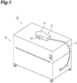
- FIG. 1 is a perspective view showing an embodiment of a spectroscopic measurement device according to one aspect of the disclosure.
- a spectroscopic measurement device 1 shown in FIG. 1 is configured as a device for measuring optical parameters of a measurement target (not shown) by electro-optical sampling.
- the measurement target is a substance such as a liquid, a powder, or a solid.
- the optical parameters to be measured include a refractive index, an absorption coefficient, and a complex permittivity.
- the spectroscopic measurement device 1 includes, for example, a box-shaped main body unit 2 having a rectangular parallelepiped shape and a measurement unit 3 including a handy type housing 4 having a measurement surface M.
- the main body unit 2 and the measurement unit 3 are physically connected to each other by a flexible cable 5 in which a polarization maintaining fiber F described later is housed. Therefore, in the spectroscopic measurement device 1, the measurement unit 3 can be freely moved with respect to the main body unit 2, so that the measurement surface M can be arranged at an arbitrary position within the range of the length of the cable 5.
- the measurement surface M is provided on the side surface of the housing 4 of the measurement unit 3, but the position of the measurement surface M in the housing 4 is arbitrary.
- FIG. 2 is a block diagram showing components of the spectroscopic measurement device shown in FIG. 1 .
- the main body unit 2 of the spectroscopic measurement device 1 is configured to include a light source unit 11 that outputs laser light L that becomes pump light La and probe light Lb, a light guide optical system 12A that guides the pump light La, a light guide optical system 12B that guides the probe light Lb, and a light detection unit 13 that detects the probe light Lb.
- each component of the main body unit 2 is a fiber-based optical component. All of the components are optically connected to each other by the polarization maintaining fiber F.
- the fiber-based optical components are components that can be optically connected to each other by a fiber. Examples of the fiber-based optical component may include a component in which at least one of the light input end and the light output end is an optical fiber.
- the polarization maintaining fiber F has, for example, a structure in which a circular stress applying portion is arranged on both sides of the core. In the polarization maintaining fiber F, by applying a non-axisymmetric stress to the core to induce a large birefringence, a function of suppressing fluctuations in polarization due to fluctuations in birefringence is obtained.
- the measurement unit 3 of the spectroscopic measurement device 1 is configured to include a terahertz wave generation unit 21 that generates a terahertz wave T in response to the input of the pump light La, a measurement prism 22 that forms the above-described measurement surface M (see FIG. 1 ), a terahertz wave detection unit 23 to which the terahertz wave T and the probe light Lb are input, and a ⁇ /8 wave plate 24.
- the light source unit 11 is a unit that outputs the laser light L that becomes the pump light La and the probe light Lb.
- the light source unit 11 is an ultrashort pulse fiber laser.
- the laser light L output from the light source unit 11 is femtosecond-order ultrashort pulse light.
- the pulse width of the laser light L is, for example, 200 fs or less.
- the laser light L has, for example, a pulse width of 60 fs, a repetition frequency of 100 MHz, and an average output of 50 mW.
- the wavelength of the laser light L is, for example, 1560 nm, which is the eye-safe band.
- the laser light L output from the light source unit 11 is branched into the pump light La and the probe light Lb by a coupler 14.
- An optical path length adjusting unit (adjustment unit) 15A, a dispersion correction patch cord 16A, and a modulation unit 17 are arranged in the light guide optical system 12A for the pump light La branched by the coupler 14.
- the optical path length adjusting unit 15A is a unit that sweeps the timing of incidence of the terahertz wave T on the terahertz wave detection unit 23 with respect to the probe light Lb.
- the optical path length adjusting unit 15A is formed by a plurality of mirrors and a delay stage including a stage for moving the positions of the mirrors.
- the pump light La propagates in free space regardless of the optical fiber (polarization maintaining fiber F).
- the pump light La is input to the dispersion correction patch cord 16A in a state in which a predetermined delay is given to the probe light Lb by the delay stage.
- the dispersion correction patch cord 16A is a unit that corrects the wavelength dispersion of light (here, the pump light La) passing through the polarization maintaining fiber F.
- the dispersion correction patch cord 16A is, for example, a dispersion compensation fiber having a length to cancel (apply reverse dispersion) the wavelength dispersion occurring according to the length of the polarization maintaining fiber F forming the light guide optical system 12A. Therefore, the pump light La is input to the modulation unit 17 in a state in which the pump light La is adjusted so that the pulse width when incident on the terahertz wave generation unit 21 is minimized.
- the modulation unit 17 is a unit that periodically switches ON/OFF of the pump light La directed to the terahertz wave generation unit 21.
- the modulation unit 17 is, for example, an optical chopper.
- the optical chopper is a disk-shaped member in which ribs for shielding light are provided radially from the center with a predetermined phase angle.
- a signal indicating the repetition frequency of ON/OFF of the pump light La by the optical chopper is output to a lock-in amplifier 32 described later that forms the light detection unit 13.
- the modulation unit 17 is not limited to the modulation by the optical chopper, and may perform other modulations using an acoustic optical element, an electro-optical element, and the like.
- An optical path length adjusting unit (adjustment unit) 15B, a dispersion correction patch cord 16B, and a circulator 18 are arranged in the light guide optical system 12B for the probe light Lb branched by the coupler 14.
- the optical path length adjusting unit 15B is a unit that adjusts the time difference between the inputs of the terahertz wave T and the probe light Lb to the terahertz wave detection unit 23.
- the optical path length adjusting unit 15B is formed by the same delay stage as the optical path length adjusting unit 15A arranged in the light guide optical system 12A.
- the probe light Lb propagates in free space regardless of the optical fiber (polarization maintaining fiber F).
- the probe light Lb is input to the dispersion correction patch cord 16B in a state in which a predetermined delay is given to the pump light La by the delay stage.
- the dispersion correction patch cord 16B is the same dispersion compensation fiber as the dispersion correction patch cord 16A arranged in the light guide optical system 12A. Therefore, the probe light Lb is input to the circulator 18 in a state in which the probe light Lb is adjusted so that the pulse width when incident on the terahertz wave detection unit 23 is minimized.
- the circulator 18 is an optical component that has three ports for light and separates two light components traveling in opposite directions from each other.
- the probe light Lb input to the port 1 of the circulator 18 is output from the port 2 toward the measurement unit 3.
- the probe light Lb returned from the measurement unit 3 to the port 2 is output from the port 3 and input to the light detection unit 13 through a polarization separation element 19.
- the pump light La input from the modulation unit 17 to the measurement unit 3 through one GRIN lens 20A is input to the terahertz wave generation unit 21.
- the terahertz wave generation unit 21 is a unit that generates the terahertz wave T by the incidence of the pump light La.
- the terahertz wave generation unit 21 may be formed of an organic nonlinear optical crystal, such as DAST (4-dimethylamino-N-methyl-4-stilbazolium tosylate), when the wavelength of the laser light L used as the pump light La is 1560 nm, for example.
- the pulse width of the terahertz wave T generated from the crystal is generally about several picoseconds, and includes frequency components in the band of about 0.1 THz to 5 THz.
- the terahertz wave T generated by the terahertz wave generation unit 21 is input to the measurement prism 22.
- the method of the present embodiment is a method called total reflection attenuation spectroscopy (ATR), and measurement is performed in a state in which a measurement target is in contact with the measurement surface M.
- the measurement prism 22 has, for example, an input surface, an output surface, and a total reflection surface.
- the total reflection surface of the measurement prism 22 is a surface corresponding to the measurement surface M described above.
- the measurement surface M is located on the optical path of the terahertz wave T between the terahertz wave generation unit 21 and the terahertz wave detection unit 23.
- the terahertz wave T is incident on the measurement prism 22 from the input surface, is totally reflected by the measurement surface M, and then is emitted from the output surface to the outside of the measurement prism 22.
- the terahertz wave T emitted outside the measurement prism 22 is input to the terahertz wave detection unit 23.
- the evanescent component generated during the total reflection of the terahertz wave T on the measurement surface M acts on the measurement target arranged on the measurement surface M. As a result, the information of the measurement target is acquired by the terahertz wave T.
- the terahertz wave detection unit 23 is a unit that detects the terahertz wave T acting on the measurement target.
- the terahertz wave detection unit 23 is formed of, for example, an electro-optical crystal obtained by cutting out the (111) plane of GaAs.
- the terahertz wave T is incident from one side of the terahertz wave detection unit 23, and the probe light Lb is incident from the other side of the terahertz wave detection unit 23.
- the refractive index changes due to the electro-optical effect according to the input of the terahertz wave T, and the probe light Lb is modulated based on the refractive index.
- the probe light Lb is input to the measurement unit 3 through the other GRIN lens 20B arranged in the measurement unit 3.
- the probe light Lb input to the measurement unit 3 passes through the ⁇ /8 wave plate 24 and is incident on the other side of the terahertz wave detection unit 23.
- the probe light Lb modulated by the terahertz wave detection unit 23 is reflected by the terahertz wave detection unit 23 and moves toward the light detection unit 13.
- the probe light Lb passes through the ⁇ /8 wave plate 24 again, and then returns to the main body unit 2 through the GRIN lens 20B.
- the probe light Lb returned to the main body unit 2 passes through the circulator 18, and input to the light detection unit 13 through the polarization separation element 19.
- the light detection unit 13 is a unit that detects the probe light Lb modulated by the terahertz wave detection unit 23.
- the light detection unit 13 is formed by a balance detector 31 and the lock-in amplifier 32.
- the polarization separation element 19 is arranged in front of the light detection unit 13.
- the polarization separation element 19 is, for example, an optical fiber fusion-type polarization beam splitter.
- the optical fiber fusion-type polarization beam splitter is an optical element that separates a first polarization component and a second polarization component of light from each other by making the light pass through an optical fiber.
- the first polarization component is, for example, a component in the same direction as the polarization of the laser light L output from the light source unit 11.
- the second polarization component is a component in a direction perpendicular to the first polarization component.
- first polarization component will be referred to as a vertical polarization component
- second polarization component will be referred to as a horizontal polarization component.
- the balance detector 31 detects a difference between the vertical polarization component and the horizontal polarization component of the probe light Lb separated by the polarization separation element 19.
- the balance detector 31 outputs a difference signal based on the difference between the vertical polarization component and the horizontal polarization component to the lock-in amplifier 32.
- the intensity fluctuation component of the probe light Lb is removed.
- it is preferable to adjust the sensitivity so that the strength of the difference signal from the balance detector 31 is zero in a state in which the terahertz wave T is not incident on the terahertz wave detection unit 23.
- An optical attenuator may be arranged between the polarization separation element 19 and the balance detector 31. By arranging the optical attenuator, the intensity of the vertical polarization component and the intensity of the horizontal polarization component input to the balance detector 31 can be easily adjusted.
- the lock-in amplifier 32 synchronously detects the difference signal output from the balance detector 31 based on the repetition frequency of ON/OFF of the pump light La by the optical chopper.
- the detection signal output from the lock-in amplifier 32 has a value depending on the electric field strength of the terahertz wave T input to the terahertz wave detection unit 23.
- the pulse width of the terahertz wave T is about picoseconds.
- the pulse width of the probe light Lb is about femtoseconds.
- the pulse width of the probe light Lb is several orders of magnitude smaller than that of the terahertz wave T. Therefore, since the timing of incidence of the terahertz wave T on the terahertz wave detection unit 23 is swept by the optical path length adjusting unit 15A, the electric field waveform (time waveform of the electric field amplitude) of the terahertz wave T can be obtained. Based on the electric field waveform of the terahertz wave T, the optical parameters of the measurement target can be obtained.
- FIG. 3 is a schematic diagram showing the principle of electro-optical sampling by the spectroscopic measurement device shown in FIG. 1 .
- a pulsed terahertz wave T is used in the electro-optical sampling of the spectroscopic measurement device 1.
- the refractive index changes due to the electro-optical effect in the terahertz wave detection unit 23.
- the electro-optical effect is a phenomenon in which the optical characteristics of a medium change depending on the electric field incident on the medium.
- the probe light Lb modulated by the terahertz wave detection unit 23 based on the refractive index changed by the electro-optical effect becomes the probe light Lb having the electric field waveform information of the terahertz wave T.
- the electric field waveform of the terahertz wave T acting on the measurement target can be acquired.
- FIGS. 4A and 4B are schematic views showing the relationship between the electric field waveform of a terahertz wave acting on a measurement target and the polarization state of modulated probe light.
- the refractive index change in the terahertz wave detection unit 23 can be read as a change in the polarization state of the probe light Lb after the terahertz wave detection unit 23.
- the initial polarization state of the probe light Lb directed to the terahertz wave detection unit 23 is linear polarization and the polarization state of the probe light Lb input to the polarization separation element 19 when the electric field strength of the terahertz wave T is zero (in the case of A and D in FIG. 4A ) is circular polarization.
- the electric field strength of the terahertz wave T is zero (in the case of A and D in FIG. 4A )
- the refractive index change in the terahertz wave detection unit 23 does not occur.
- the polarization state of the probe light Lb after the terahertz wave detection unit 23 is maintained in the initial polarization state.
- the output from the balance detector 31 is zero.
- the electric field strength of the terahertz wave T is larger than zero (in the case of B and C in FIG.
- the refractive index change in the terahertz wave detection unit 23 occurs according to the electric field strength of the terahertz wave T.
- the output from the balance detector 31 is a value (non-zero value) corresponding to the electric field strength of the terahertz wave T.
- the main body unit 2 and the measurement unit 3 are optically connected to each other by the polarization maintaining fiber F.
- the optical components forming the main body unit 2 are also optically connected to each other by the polarization maintaining fiber F.
- the polarization maintaining fiber F a non-axisymmetric stress is applied to the core, so that the refractive index for the vertical polarization component of the propagating light and the refractive index for the horizontal polarization component of the propagating light are different from each other. Therefore, in the light propagating through the polarization maintaining fiber F, there may be a difference in output timing between the vertical polarization component and the horizontal polarization component.
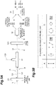
- FIG. 5A in a mode in which the terahertz wave T is incident from one side of the terahertz wave detection unit 23 and the probe light Lb is incident from the other side of the terahertz wave detection unit 23, for example, a case where a ⁇ /4 wave plate 101 is arranged between the circulator 18 and the polarization separation element 19 is assumed.
- FIG. 5B assuming that the probe light Lb (A in FIG. 5A ) directed to the terahertz wave detection unit 23 is linearly polarized light and the probe light Lb modulated by the terahertz wave detection unit 23 (B in FIG. 5A ) is elliptically polarized light, the probe light Lb (C in FIG. 5A ) directed from the circulator 18 to the polarization separation element 19 becomes two linearly polarized light components with different timings.
- the probe light Lb passes through the ⁇ /4 wave plate 101 immediately before being input to the polarization separation element 19, the probe light Lb (D in FIG. 5A ) transmitted through the ⁇ /4 wave plate 101 becomes two circularly polarized light components with different timings.
- the difference value output from the balance detector 31 is zero.
- the polarization state of the probe light Lb detected by the light detection unit 13 is the same as in the case of linear polarization and a detection result that the electric field strength of the terahertz wave T is zero is obtained.
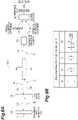
- the ⁇ /8 wave plate 24 is arranged on the optical path where the probe light Lb modulated by the terahertz wave detection unit 23 is directed to the light detection unit 13, more specifically, arranged between the terahertz wave detection unit 23 and the GRIN lens 20B (see FIG. 2 ) in the measurement unit 3.
- the probe light Lb (A in FIG. 6A ) directed from the circulator 18 to the ⁇ /8 wave plate 24 is linearly polarized light
- the probe light Lb (B in FIG. 6A ) modulated by the terahertz wave detection unit 23 is elliptically polarized light having a phase corresponding to a change in the refractive index.
- the difference value is a non-zero value. Therefore, the electric field waveform of the terahertz wave T based on the polarization state of the probe light Lb can be easily restored.
- the timing difference between the two linearly polarized light components in the probe light Lb is approximately on the order of picoseconds.
- difference detection is performed on the assumption that two linearly polarized light components in the probe light Lb are simultaneously input to the balance detector without the timing difference therebetween. Therefore, for the probe light Lb after passing through the ⁇ /8 wave plate 24, even if the linearly polarized light component is separated in time by the action of the polarization maintaining fiber F, there is no influence on the measurement of the terahertz wave T.
- the change in the refractive index of the terahertz wave detection unit 23 is sampled with the probe light Lb by the electro-optical effect according to the input of the terahertz wave T. Therefore, the electric field waveform of the terahertz wave T acting on the measurement target can be acquired, and the information of the measurement target can be acquired based on the electric field waveform.
- the measurement unit 3 is optically connected to the main body unit 2 by the polarization maintaining fiber F. Therefore, since the measurement unit 3 (measurement surface M) can be freely arranged with respect to the main body unit 2, it is possible to improve the accessibility of the measurement unit 3 to the measurement target.
- the polarization state of the probe light Lb input to the terahertz wave detection unit 23 is maintained by using the polarization maintaining fiber F, so that the detection efficiency of the probe light Lb in the light detection unit 13 can also be maintained.
- the terahertz wave detection unit 23 is formed of an electro-optical crystal, it is not necessary to take measures against electromagnetic compatibility (EMC).
- EMC electromagnetic compatibility
- the terahertz wave detection unit 23 is a photoconductive antenna, an electric signal is used in the terahertz wave detection unit 23. Therefore, in the measurement unit 3, it is necessary to design the housing 4 including an electromagnetic shield in addition to noise countermeasures.
- the housing 4 of the measurement unit 3 can be formed of plastic or the like without an electromagnetic shield.
- the spectroscopic measurement device 1 is configured to include a wave plate arranged on the optical path where the probe light Lb modulated by the terahertz wave detection unit 23 is directed to the light detection unit 13.
- the wave plate is the ⁇ /8 wave plate 24, and in the measurement unit 3, the terahertz wave T is incident from one side of the terahertz wave detection unit 23, and the probe light Lb is incident from the other side of the terahertz wave detection unit 23 and reflected toward the light detection unit 13.
- the polarization components of the probe light Lb can be appropriately separated into a vertical polarization component and a horizontal polarization component by making the probe light Lb incident on the ⁇ /8 wave plate 24 twice before and after the input to the terahertz wave detection unit 23. Therefore, the detection efficiency of the probe light Lb in the light detection unit 13 can be appropriately guaranteed.
- the optical components forming the main body unit 2 are optically connected by the polarization maintaining fiber F.
- the optical components forming the main body unit 2 are all fiber-based optical components except for the optical path length adjusting units 15A and 15B, and all of these components are optically connected to each other by the polarization maintaining fiber F. Therefore, it is possible to increase the degree of freedom in arranging the optical components in the main body unit 2. This also contributes to the miniaturization of the main body unit 2.
- the main body unit 2 is configured to include the optical path length adjusting units 15A and 15B for adjusting the optical path length difference between the pump light La and the probe light Lb. Therefore, the input timings of the terahertz wave T and the probe light Lb to the terahertz wave detection unit 23 can be freely adjusted. For example, by sweeping the input timing of the probe light Lb to the terahertz wave detection unit 23 with the optical path length adjusting unit 15A, the electric field waveform of the terahertz wave T acting on the measurement target can be appropriately acquired.
- each of the optical path length adjusting units 15A and 15B is configured to include a plurality of mirrors and a stage for moving the positions of the mirrors, and the pump light La or the probe light Lb propagates in free space regardless of the optical fiber. Therefore, the optical path length adjusting units 15A and 15B can be constructed with a simple configuration.
- the light source unit 11 is a fiber laser. Therefore, since the size of the light source unit 11 can be reduced, the size of the main body unit 2 can be further reduced.
- the wave plate is the ⁇ /8 wave plate 24, and in the measurement unit 3, the terahertz wave T is incident from one side of the terahertz wave detection unit 23, and the probe light Lb is incident from the other side of the terahertz wave detection unit 23 and reflected toward the light detection unit 13.
- the configuration of the measurement unit 3 may be differently set.
- the wave plate may be a ⁇ /4 wave plate 41, and in the measurement unit 3, the terahertz wave T and the probe light Lb may be incident from one side of the terahertz wave detection unit 23, and the probe light Lb may be transmitted to the other side of the terahertz wave detection unit 23 and directed toward the light detection unit 13.
- the probe light Lb directed to the polarization separation element 19 can be made to be two linearly polarized light components with different timings by making the probe light Lb after the terahertz wave detection unit 23 incident on the ⁇ /4 wave plate 41 once. Therefore, since the polarization components of the probe light Lb can be appropriately separated into the vertical polarization component and the horizontal polarization component, the detection efficiency of the probe light Lb in the light detection unit 13 can be appropriately guaranteed.
- a fiber coupling element 42 is arranged on the rear side of the ⁇ /4 wave plate 41 in order to guide the probe light Lb modulated by the terahertz wave detection unit 23 from the measurement unit 3 to the main body unit 2.
- the fiber coupling element 42 is, for example, a lens.
- the fiber coupling element 42 causes the probe light Lb transmitted through the ⁇ /4 wave plate 41 to be incident on the polarization maintaining fiber F that optically connects the main body unit 2 and the measurement unit 3 to each other.
- each of the optical path length adjusting units 15A and 15B is configured to include a plurality of mirrors and a stage for moving the positions of the mirrors, and the pump light La or the probe light Lb propagates in free space regardless of the optical fiber.
- at least one of the optical path length adjusting units 15A and 15B may be the polarization maintaining fiber F.
- the degree of freedom in arranging the optical components in the main body unit 2 can be further increased.
- the size of the main body unit 2 can be further reduced.
- each of the optical path length adjusting units 15A and 15B is the polarization maintaining fiber F
- a configuration can be considered in which the polarization maintaining fiber F having a predetermined length is wound around a piezoelectric element.
- the fiber length of the polarization maintaining fiber F wound around the piezoelectric element can be adjusted by applying a voltage to the piezoelectric element to change the volume. Therefore, it is possible to accurately control the optical path length of the pump light La or the probe light Lb.
- the dispersion correction patch cord 16A is arranged in the light guide optical system 12A for the pump light La
- the dispersion correction patch cord 16B is arranged in the light guide optical system 12B for the probe light Lb.
- the dispersion correction patch cords 16A and 16B do not necessarily have to be used.
- the spectroscopic measurement device 1 may be configured by using a laser light source to which anomalous dispersion is given in advance so that the pulse widths of the pump light La and the probe light Lb, which have propagated by a predetermined distance, are the shortest when the pump light La and the probe light Lb are incident on the terahertz wave generation unit 21 and the terahertz wave detection unit 23.
- a polarization holding patch cord may be used, or the polarization holding patch cord and the dispersion correction patch cord may be used in combination.
- a wave plate ( ⁇ /8 wave plate 24, ⁇ /4 wave plate 41) is provided on the optical path where the probe light Lb modulated by the terahertz wave detection unit 23 is directed to the light detection unit 13.
- the wave plate instead of the wave plate, other elements capable of adjusting the polarization state of the probe light Lb may be arranged. Examples of such an element include a Faraday rotator.
- a polarized rotator for example, a quartz polarized rotator
- the measurement method in the spectroscopic measurement device 1 is not limited to this.
- the terahertz wave T emitted from the measurement surface M into the free space may be applied to the measurement target, and the reflected light of the terahertz wave T may be incident on the measurement surface M again to be detected by the terahertz wave detection unit 23.
- the terahertz wave T emitted from the measurement surface M into the free space may be applied to the measurement target, and the transmitted light of the terahertz wave T may be reflected by a mirror or the like and be incident on the measurement surface M again to be detected by the terahertz wave detection unit 23.
- the measurement surface M may not be provided on the housing 4 of the measurement unit 3, and the measurement target may be arranged in the housing 4.
- the arrangement of the measurement prism 22 may be omitted, and instead, the measurement target may be arranged between the terahertz wave generation unit 21 and the terahertz wave detection unit 23. Then, the terahertz wave T generated by the terahertz wave generation unit 21 may be applied to the measurement target, and the transmitted light of the terahertz wave T may be detected by the terahertz wave detection unit 23.
Landscapes
- Physics & Mathematics (AREA)
- Spectroscopy & Molecular Physics (AREA)
- General Physics & Mathematics (AREA)
- Health & Medical Sciences (AREA)
- Chemical & Material Sciences (AREA)
- Life Sciences & Earth Sciences (AREA)
- Analytical Chemistry (AREA)
- Biochemistry (AREA)
- General Health & Medical Sciences (AREA)
- Immunology (AREA)
- Pathology (AREA)
- Toxicology (AREA)
- Investigating Or Analysing Materials By Optical Means (AREA)
Abstract
Description
- The present disclosure relates to a spectroscopic measurement device.
- The terahertz wave is an electromagnetic wave having a frequency of about 0.01 THz to 100 THz, which corresponds to an intermediate region between a light wave and a radio wave. The terahertz wave has an intermediate property between the light wave and the radio wave. As an application of the terahertz wave, a technique for acquiring information regarding a measurement target by measuring the time waveform of the electric field amplitude of the terahertz wave transmitted or reflected by the measurement target has been studied.
- Examples of the spectroscopic measurement device using the terahertz wave include the devices described in
Japanese Unexamined Patent Publication No. 2019-20293 Japanese Unexamined Patent Publication No. 2020-20641 - In the field of time domain spectroscopy including spectroscopic measurement using terahertz waves, it is very important to secure the optical path length in the measurement optical system. It is not easy to change the layout of the optical system once determined. For example, in the spectroscopic measurement device described in
Japanese Unexamined Patent Publication No. 2019-20293 - If the positions of measurement units are unchanged, it is conceivable that the shape, posture, and the like of a measurement target that can access the measurement unit (for example, come into contact with the measurement surface) are limited. In addition, it is conceivable that devices, production lines, and the like where the spectroscopic measurement device can be housed are limited. Therefore, in order to expand the use of the spectroscopic measurement device in the industrial field, it is necessary to improve the accessibility of the measurement unit to the measurement target.
- The disclosure has been made to solve the aforementioned problems, and it is an object of the disclosure to provide a spectroscopic measurement device capable of improving the accessibility of a measurement unit to a measurement target.
- A spectroscopic measurement device according to an aspect of the disclosure includes: a light source unit for outputting pump light and probe light; a terahertz wave generation unit for generating a terahertz wave by input of the pump light; a terahertz wave detection unit to which the terahertz wave and the probe light are input and which modulates the probe light based on a refractive index that changes due to an electro-optical effect according to input of the terahertz wave; and a light detection unit for detecting the probe light modulated by the terahertz wave detection unit. A main body unit is configured to include the light source unit and the light detection unit. A measurement unit is configured to include the terahertz wave generation unit and the terahertz wave detection unit. The main body unit and the measurement unit are optically connected to each other by a polarization maintaining fiber.
- In the spectroscopic measurement device, the change in the refractive index of the terahertz wave detection unit is sampled with the probe light by the electro-optical effect according to the input of the terahertz wave. Therefore, the electric field waveform of the terahertz wave acting on the measurement target can be acquired, and the information of the measurement target can be acquired based on the electric field waveform. In addition, in the spectroscopic measurement device, the measurement unit is optically connected to the main body unit by the polarization maintaining fiber. Therefore, since the measurement unit can be freely arranged with respect to the main body unit, it is possible to improve the accessibility of the measurement unit to the measurement target. Restrictions on the shape or posture of the measurement target that can access the measurement unit can be eliminated, and the number of devices, production lines, and the like where the spectroscopic measurement device can be housed increases. Therefore, the applications of the spectroscopic measurement device in the industrial field will be expanded. The polarization state of the probe light input to the terahertz wave detection unit is maintained by using the polarization maintaining fiber, so that the detection efficiency of the probe light in the light detection unit can also be maintained.
- The measurement unit may have a measurement surface on an optical path of the terahertz wave between the terahertz wave generation unit and the terahertz wave detection unit. By providing the measurement surface on the measurement unit that can be freely arranged with respect to the main body unit, it is possible to further improve the accessibility of the measurement unit to the measurement target.
- The measurement unit may be configured to further include a wave plate arranged on an optical path where the probe light modulated by the terahertz wave detection unit is directed to the light detection unit. In the polarization maintaining fiber, since the refractive index differs between the first polarization component and the second polarization component perpendicular to the first polarization component, it is conceivable that the first polarization component and the second polarization component of the propagated light are time-shifted. Therefore, by arranging the wave plate at an appropriate position in the measurement unit, the detection efficiency of the probe light in the light detection unit can be guaranteed.
- The wave plate may be a λ/8 wave plate, and in the measurement unit, the terahertz wave may be incident from one side of the terahertz wave detection unit, and the probe light may be incident from the other side of the terahertz wave detection unit and reflected toward the light detection unit. According to this configuration, for example, assuming that the initial polarization state of the probe light is linear polarization, the polarization components of the probe light can be appropriately separated into the first polarization component and the second polarization component by making the probe light incident on the λ/8 wave plate twice before and after the input to the terahertz wave detection unit. Therefore, the detection efficiency of the probe light in the light detection unit can be appropriately guaranteed.
- The wave plate may be a λ/4 wave plate, and in the measurement unit, the terahertz wave and the probe light may be incident from one side of the terahertz wave detection unit, and the probe light may be transmitted to the other side of the terahertz wave detection unit and directed toward the light detection unit. According to this configuration, for example, assuming that the initial polarization state of the probe light is linear polarization, the polarization components of the probe light can be appropriately separated into the first polarization component and the second polarization component by making the probe light after the terahertz wave detection unit incident on the λ/4 wave plate once. Therefore, the detection efficiency of the probe light in the light detection unit can be appropriately guaranteed.
- At least some of optical components forming the main body unit may be optically connected to each other by a polarization maintaining fiber. Therefore, it is possible to increase the degree of freedom in arranging the optical components in the main body unit. This also contributes to the miniaturization of the main body unit.
- The main body unit may be configured to include an adjustment unit for adjusting an optical path length difference between the pump light and the probe light. Therefore, the input timings of the terahertz wave and the probe light to the terahertz wave detection unit can be freely adjusted. By sweeping the input timing of the probe light to the terahertz wave detection unit with the adjusting unit, the electric field waveform of the terahertz wave acting on the measurement target can be appropriately acquired.
- The adjustment unit may be configured to include a plurality of mirrors and a stage for moving positions of the mirrors, and the pump light or the probe light may propagate in free space without depending on an optical fiber. In this case, the adjustment unit can be constructed with a simple configuration.
- The adjustment unit may be a polarization maintaining fiber. In this case, the degree of freedom in arranging the optical components in the main body unit can be further increased. In addition, the size of the main body unit can be further reduced.
- The light source unit may be a fiber laser. In this case, since the size of the light source unit can be reduced, the size of the main body unit can be further reduced.
- Laser light output from the light source unit may be femtosecond-order ultrashort pulse light. By using the ultrashort pulse light, the bandwidth of the terahertz wave generated by the terahertz wave generation unit is expanded, so that the measurement bandwidth of the spectroscopic measurement device can be expanded.
-
-
FIG. 1 is a perspective view showing an embodiment of a spectroscopic measurement device according to an aspect of the disclosure. -
FIG. 2 is a block diagram showing components of the spectroscopic measurement device shown inFIG. 1 . -
FIG. 3 is a schematic diagram showing the principle of electro-optical sampling by the spectroscopic measurement device shown inFIG. 1 . -
FIG. 4A is a schematic diagram showing the relationship between the electric field waveform of a terahertz wave acting on a measurement target and the polarization state of modulated probe light. -
FIG. 4B is a schematic diagram showing the relationship between the electric field waveform of a terahertz wave acting on a measurement target and the polarization state of modulated probe light. -
FIG. 5A is a schematic diagram showing a polarization state of probe light according to a comparative example. -
FIG. 5B is a schematic diagram showing a polarization state of probe light according to the comparative example. -
FIG. 6A is a schematic diagram showing a polarization state of probe light according to an embodiment. -
FIG. 6B is a schematic diagram showing a polarization state of probe light according to the embodiment. -
FIG. 7 is a block diagram showing main components of a spectroscopic measurement device according to a modification example. - Hereinafter, preferred embodiments of a spectroscopic measurement device according to an aspect of the disclosure will be described in detail with reference to the diagrams.
-
FIG. 1 is a perspective view showing an embodiment of a spectroscopic measurement device according to one aspect of the disclosure. Aspectroscopic measurement device 1 shown inFIG. 1 is configured as a device for measuring optical parameters of a measurement target (not shown) by electro-optical sampling. The measurement target is a substance such as a liquid, a powder, or a solid. Examples of the optical parameters to be measured include a refractive index, an absorption coefficient, and a complex permittivity. - As shown in
FIG. 1 , thespectroscopic measurement device 1 includes, for example, a box-shapedmain body unit 2 having a rectangular parallelepiped shape and ameasurement unit 3 including ahandy type housing 4 having a measurement surface M. Themain body unit 2 and themeasurement unit 3 are physically connected to each other by aflexible cable 5 in which a polarization maintaining fiber F described later is housed. Therefore, in thespectroscopic measurement device 1, themeasurement unit 3 can be freely moved with respect to themain body unit 2, so that the measurement surface M can be arranged at an arbitrary position within the range of the length of thecable 5. InFIG. 1 , the measurement surface M is provided on the side surface of thehousing 4 of themeasurement unit 3, but the position of the measurement surface M in thehousing 4 is arbitrary. -
FIG. 2 is a block diagram showing components of the spectroscopic measurement device shown inFIG. 1 . As shown inFIG. 2 , themain body unit 2 of thespectroscopic measurement device 1 is configured to include alight source unit 11 that outputs laser light L that becomes pump light La and probe light Lb, a light guideoptical system 12A that guides the pump light La, a light guideoptical system 12B that guides the probe light Lb, and alight detection unit 13 that detects the probe light Lb. - In the present embodiment, each component of the
main body unit 2 is a fiber-based optical component. All of the components are optically connected to each other by the polarization maintaining fiber F. The fiber-based optical components are components that can be optically connected to each other by a fiber. Examples of the fiber-based optical component may include a component in which at least one of the light input end and the light output end is an optical fiber. The polarization maintaining fiber F has, for example, a structure in which a circular stress applying portion is arranged on both sides of the core. In the polarization maintaining fiber F, by applying a non-axisymmetric stress to the core to induce a large birefringence, a function of suppressing fluctuations in polarization due to fluctuations in birefringence is obtained. - The
measurement unit 3 of thespectroscopic measurement device 1 is configured to include a terahertzwave generation unit 21 that generates a terahertz wave T in response to the input of the pump light La, ameasurement prism 22 that forms the above-described measurement surface M (seeFIG. 1 ), a terahertzwave detection unit 23 to which the terahertz wave T and the probe light Lb are input, and a λ/8wave plate 24. - The
light source unit 11 is a unit that outputs the laser light L that becomes the pump light La and the probe light Lb. In the present embodiment, thelight source unit 11 is an ultrashort pulse fiber laser. The laser light L output from thelight source unit 11 is femtosecond-order ultrashort pulse light. The pulse width of the laser light L is, for example, 200 fs or less. In the present embodiment, the laser light L has, for example, a pulse width of 60 fs, a repetition frequency of 100 MHz, and an average output of 50 mW. The wavelength of the laser light L is, for example, 1560 nm, which is the eye-safe band. The laser light L output from thelight source unit 11 is branched into the pump light La and the probe light Lb by acoupler 14. - An optical path length adjusting unit (adjustment unit) 15A, a dispersion
correction patch cord 16A, and amodulation unit 17 are arranged in the light guideoptical system 12A for the pump light La branched by thecoupler 14. The optical pathlength adjusting unit 15A is a unit that sweeps the timing of incidence of the terahertz wave T on the terahertzwave detection unit 23 with respect to the probe light Lb. In the present embodiment, the optical pathlength adjusting unit 15A is formed by a plurality of mirrors and a delay stage including a stage for moving the positions of the mirrors. In the optical pathlength adjusting unit 15A, the pump light La propagates in free space regardless of the optical fiber (polarization maintaining fiber F). The pump light La is input to the dispersioncorrection patch cord 16A in a state in which a predetermined delay is given to the probe light Lb by the delay stage. - The dispersion
correction patch cord 16A is a unit that corrects the wavelength dispersion of light (here, the pump light La) passing through the polarization maintaining fiber F. The dispersioncorrection patch cord 16A is, for example, a dispersion compensation fiber having a length to cancel (apply reverse dispersion) the wavelength dispersion occurring according to the length of the polarization maintaining fiber F forming the light guideoptical system 12A. Therefore, the pump light La is input to themodulation unit 17 in a state in which the pump light La is adjusted so that the pulse width when incident on the terahertzwave generation unit 21 is minimized. - The
modulation unit 17 is a unit that periodically switches ON/OFF of the pump light La directed to the terahertzwave generation unit 21. Themodulation unit 17 is, for example, an optical chopper. The optical chopper is a disk-shaped member in which ribs for shielding light are provided radially from the center with a predetermined phase angle. By periodically switching ON/OFF of the pump light La by the rotation of the optical chopper, the timing of generation of the terahertz wave T in the terahertzwave generation unit 21 is controlled. A signal indicating the repetition frequency of ON/OFF of the pump light La by the optical chopper is output to a lock-inamplifier 32 described later that forms thelight detection unit 13. Themodulation unit 17 is not limited to the modulation by the optical chopper, and may perform other modulations using an acoustic optical element, an electro-optical element, and the like. - An optical path length adjusting unit (adjustment unit) 15B, a dispersion
correction patch cord 16B, and acirculator 18 are arranged in the light guideoptical system 12B for the probe light Lb branched by thecoupler 14. The optical pathlength adjusting unit 15B is a unit that adjusts the time difference between the inputs of the terahertz wave T and the probe light Lb to the terahertzwave detection unit 23. In the present embodiment, the optical pathlength adjusting unit 15B is formed by the same delay stage as the optical pathlength adjusting unit 15A arranged in the light guideoptical system 12A. In the optical pathlength adjusting unit 15B, the probe light Lb propagates in free space regardless of the optical fiber (polarization maintaining fiber F). The probe light Lb is input to the dispersioncorrection patch cord 16B in a state in which a predetermined delay is given to the pump light La by the delay stage. - In the present embodiment, the dispersion
correction patch cord 16B is the same dispersion compensation fiber as the dispersioncorrection patch cord 16A arranged in the light guideoptical system 12A. Therefore, the probe light Lb is input to thecirculator 18 in a state in which the probe light Lb is adjusted so that the pulse width when incident on the terahertzwave detection unit 23 is minimized. Thecirculator 18 is an optical component that has three ports for light and separates two light components traveling in opposite directions from each other. The probe light Lb input to theport 1 of thecirculator 18 is output from theport 2 toward themeasurement unit 3. The probe light Lb returned from themeasurement unit 3 to theport 2 is output from theport 3 and input to thelight detection unit 13 through apolarization separation element 19. - The pump light La transmitted through the
modulation unit 17 and the probe light Lb output from theport 2 of thecirculator 18 reach themeasurement unit 3 through the polarization maintaining fiber F housed in the cable 5 (seeFIG. 1 ), and are emitted fromGRIN lenses main body unit 2 and themeasurement unit 3 is realized by two refractive index distribution type lenses (GRIN lenses) 20A and 20B arranged in themeasurement unit 3. The pump light La input from themodulation unit 17 to themeasurement unit 3 through oneGRIN lens 20A is input to the terahertzwave generation unit 21. - The terahertz
wave generation unit 21 is a unit that generates the terahertz wave T by the incidence of the pump light La. The terahertzwave generation unit 21 may be formed of an organic nonlinear optical crystal, such as DAST (4-dimethylamino-N-methyl-4-stilbazolium tosylate), when the wavelength of the laser light L used as the pump light La is 1560 nm, for example. The pulse width of the terahertz wave T generated from the crystal is generally about several picoseconds, and includes frequency components in the band of about 0.1 THz to 5 THz. The terahertz wave T generated by the terahertzwave generation unit 21 is input to themeasurement prism 22. - The method of the present embodiment is a method called total reflection attenuation spectroscopy (ATR), and measurement is performed in a state in which a measurement target is in contact with the measurement surface M. The
measurement prism 22 has, for example, an input surface, an output surface, and a total reflection surface. The total reflection surface of themeasurement prism 22 is a surface corresponding to the measurement surface M described above. The measurement surface M is located on the optical path of the terahertz wave T between the terahertzwave generation unit 21 and the terahertzwave detection unit 23. The terahertz wave T is incident on themeasurement prism 22 from the input surface, is totally reflected by the measurement surface M, and then is emitted from the output surface to the outside of themeasurement prism 22. The terahertz wave T emitted outside themeasurement prism 22 is input to the terahertzwave detection unit 23. The evanescent component generated during the total reflection of the terahertz wave T on the measurement surface M acts on the measurement target arranged on the measurement surface M. As a result, the information of the measurement target is acquired by the terahertz wave T. - The terahertz
wave detection unit 23 is a unit that detects the terahertz wave T acting on the measurement target. The terahertzwave detection unit 23 is formed of, for example, an electro-optical crystal obtained by cutting out the (111) plane of GaAs. In the present embodiment, the terahertz wave T is incident from one side of the terahertzwave detection unit 23, and the probe light Lb is incident from the other side of the terahertzwave detection unit 23. In the terahertzwave detection unit 23, the refractive index changes due to the electro-optical effect according to the input of the terahertz wave T, and the probe light Lb is modulated based on the refractive index. - The probe light Lb is input to the
measurement unit 3 through theother GRIN lens 20B arranged in themeasurement unit 3. The probe light Lb input to themeasurement unit 3 passes through the λ/8wave plate 24 and is incident on the other side of the terahertzwave detection unit 23. The probe light Lb modulated by the terahertzwave detection unit 23 is reflected by the terahertzwave detection unit 23 and moves toward thelight detection unit 13. The probe light Lb passes through the λ/8wave plate 24 again, and then returns to themain body unit 2 through theGRIN lens 20B. The probe light Lb returned to themain body unit 2 passes through thecirculator 18, and input to thelight detection unit 13 through thepolarization separation element 19. - The
light detection unit 13 is a unit that detects the probe light Lb modulated by the terahertzwave detection unit 23. In the present embodiment, thelight detection unit 13 is formed by abalance detector 31 and the lock-inamplifier 32. Thepolarization separation element 19 is arranged in front of thelight detection unit 13. Thepolarization separation element 19 is, for example, an optical fiber fusion-type polarization beam splitter. The optical fiber fusion-type polarization beam splitter is an optical element that separates a first polarization component and a second polarization component of light from each other by making the light pass through an optical fiber. The first polarization component is, for example, a component in the same direction as the polarization of the laser light L output from thelight source unit 11. The second polarization component is a component in a direction perpendicular to the first polarization component. Hereinafter, for convenience of explanation, the first polarization component will be referred to as a vertical polarization component, and the second polarization component will be referred to as a horizontal polarization component. - The
balance detector 31 detects a difference between the vertical polarization component and the horizontal polarization component of the probe light Lb separated by thepolarization separation element 19. Thebalance detector 31 outputs a difference signal based on the difference between the vertical polarization component and the horizontal polarization component to the lock-inamplifier 32. By performing the difference detection, the intensity fluctuation component of the probe light Lb is removed. In performing the difference detection, it is preferable to adjust the sensitivity so that the strength of the difference signal from thebalance detector 31 is zero in a state in which the terahertz wave T is not incident on the terahertzwave detection unit 23. An optical attenuator may be arranged between thepolarization separation element 19 and thebalance detector 31. By arranging the optical attenuator, the intensity of the vertical polarization component and the intensity of the horizontal polarization component input to thebalance detector 31 can be easily adjusted. - The lock-in
amplifier 32 synchronously detects the difference signal output from thebalance detector 31 based on the repetition frequency of ON/OFF of the pump light La by the optical chopper. The detection signal output from the lock-inamplifier 32 has a value depending on the electric field strength of the terahertz wave T input to the terahertzwave detection unit 23. - Generally, the pulse width of the terahertz wave T is about picoseconds. On the other hand, the pulse width of the probe light Lb is about femtoseconds. The pulse width of the probe light Lb is several orders of magnitude smaller than that of the terahertz wave T. Therefore, since the timing of incidence of the terahertz wave T on the terahertz
wave detection unit 23 is swept by the optical pathlength adjusting unit 15A, the electric field waveform (time waveform of the electric field amplitude) of the terahertz wave T can be obtained. Based on the electric field waveform of the terahertz wave T, the optical parameters of the measurement target can be obtained. -
FIG. 3 is a schematic diagram showing the principle of electro-optical sampling by the spectroscopic measurement device shown inFIG. 1 . As shown inFIG. 3 , in the electro-optical sampling of thespectroscopic measurement device 1, a pulsed terahertz wave T is used. With the input of the terahertz wave T, the refractive index changes due to the electro-optical effect in the terahertzwave detection unit 23. The electro-optical effect is a phenomenon in which the optical characteristics of a medium change depending on the electric field incident on the medium. The probe light Lb modulated by the terahertzwave detection unit 23 based on the refractive index changed by the electro-optical effect becomes the probe light Lb having the electric field waveform information of the terahertz wave T. By sampling the refractive index change in the terahertzwave detection unit 23 with the probe light Lb, the electric field waveform of the terahertz wave T acting on the measurement target can be acquired. -
FIGS. 4A and 4B are schematic views showing the relationship between the electric field waveform of a terahertz wave acting on a measurement target and the polarization state of modulated probe light. As shown inFIGS. 4A and 4B , the refractive index change in the terahertzwave detection unit 23 can be read as a change in the polarization state of the probe light Lb after the terahertzwave detection unit 23. For example, it is preferable that the initial polarization state of the probe light Lb directed to the terahertzwave detection unit 23 is linear polarization and the polarization state of the probe light Lb input to thepolarization separation element 19 when the electric field strength of the terahertz wave T is zero (in the case of A and D inFIG. 4A ) is circular polarization. - For example, when the electric field strength of the terahertz wave T is zero (in the case of A and D in
FIG. 4A ), the refractive index change in the terahertzwave detection unit 23 does not occur. In this case, the polarization state of the probe light Lb after the terahertzwave detection unit 23 is maintained in the initial polarization state. At this time, if the polarization state of the probe light Lb input to thepolarization separation element 19 is circular polarization, the output from thebalance detector 31 is zero. On the other hand, when the electric field strength of the terahertz wave T is larger than zero (in the case of B and C inFIG. 4A ), the refractive index change in the terahertzwave detection unit 23 occurs according to the electric field strength of the terahertz wave T. At this time, if the polarization state of the probe light Lb after the terahertzwave detection unit 23 changes to elliptical polarization having a phase corresponding to the refractive index change, the output from thebalance detector 31 is a value (non-zero value) corresponding to the electric field strength of the terahertz wave T. - Next, a method for restoring the electric field waveform of the terahertz wave based on the polarization state of the probe light will be described. As described above, in the
spectroscopic measurement device 1, themain body unit 2 and themeasurement unit 3 are optically connected to each other by the polarization maintaining fiber F. In addition, the optical components forming themain body unit 2 are also optically connected to each other by the polarization maintaining fiber F. In the polarization maintaining fiber F, a non-axisymmetric stress is applied to the core, so that the refractive index for the vertical polarization component of the propagating light and the refractive index for the horizontal polarization component of the propagating light are different from each other. Therefore, in the light propagating through the polarization maintaining fiber F, there may be a difference in output timing between the vertical polarization component and the horizontal polarization component. - As a comparative example, as shown in
FIG. 5A , in a mode in which the terahertz wave T is incident from one side of the terahertzwave detection unit 23 and the probe light Lb is incident from the other side of the terahertzwave detection unit 23, for example, a case where a λ/4wave plate 101 is arranged between the circulator 18 and thepolarization separation element 19 is assumed. In this case, as shown inFIG. 5B , assuming that the probe light Lb (A inFIG. 5A ) directed to the terahertzwave detection unit 23 is linearly polarized light and the probe light Lb modulated by the terahertz wave detection unit 23 (B inFIG. 5A ) is elliptically polarized light, the probe light Lb (C inFIG. 5A ) directed from thecirculator 18 to thepolarization separation element 19 becomes two linearly polarized light components with different timings. - When the probe light Lb passes through the λ/4
wave plate 101 immediately before being input to thepolarization separation element 19, the probe light Lb (D inFIG. 5A ) transmitted through the λ/4wave plate 101 becomes two circularly polarized light components with different timings. In this case, since the vertical polarization component and the horizontal polarization component of the probe light Lb separated by thepolarization separation element 19 are equal, the difference value output from thebalance detector 31 is zero. Therefore, it is assumed that, despite a change in the refractive index in the terahertzwave detection unit 23, the polarization state of the probe light Lb detected by thelight detection unit 13 is the same as in the case of linear polarization and a detection result that the electric field strength of the terahertz wave T is zero is obtained. - On the other hand, in the
spectroscopic measurement device 1, as shown inFIG. 6A , the λ/8wave plate 24 is arranged on the optical path where the probe light Lb modulated by the terahertzwave detection unit 23 is directed to thelight detection unit 13, more specifically, arranged between the terahertzwave detection unit 23 and theGRIN lens 20B (seeFIG. 2 ) in themeasurement unit 3. In this configuration, as shown inFIG. 6B , the probe light Lb (A inFIG. 6A ) directed from thecirculator 18 to the λ/8wave plate 24 is linearly polarized light, and the probe light Lb (B inFIG. 6A ) modulated by the terahertzwave detection unit 23 is elliptically polarized light having a phase corresponding to a change in the refractive index. - The probe light Lb (C in
FIG. 6A ) reflected by the terahertzwave detection unit 23 and transmitted through the λ/8wave plate 24 again becomes elliptically polarized light having different ellipticity, and the probe light Lb (D inFIG. 6A ) directed from thecirculator 18 to thepolarization separation element 19 becomes two linearly polarized light components with different timings. When a difference value between the vertical polarization component and the horizontal polarization component of the probe light Lb separated by thepolarization separation element 19 is detected by thebalance detector 31, the difference value is a non-zero value. Therefore, the electric field waveform of the terahertz wave T based on the polarization state of the probe light Lb can be easily restored. - The timing difference between the two linearly polarized light components in the probe light Lb is approximately on the order of picoseconds. In a balance detector below the MHz band that is usually used for this type of spectroscopic measurement, difference detection is performed on the assumption that two linearly polarized light components in the probe light Lb are simultaneously input to the balance detector without the timing difference therebetween. Therefore, for the probe light Lb after passing through the λ/8
wave plate 24, even if the linearly polarized light component is separated in time by the action of the polarization maintaining fiber F, there is no influence on the measurement of the terahertz wave T. - As described above, in the
spectroscopic measurement device 1, the change in the refractive index of the terahertzwave detection unit 23 is sampled with the probe light Lb by the electro-optical effect according to the input of the terahertz wave T. Therefore, the electric field waveform of the terahertz wave T acting on the measurement target can be acquired, and the information of the measurement target can be acquired based on the electric field waveform. In addition, in thespectroscopic measurement device 1, themeasurement unit 3 is optically connected to themain body unit 2 by the polarization maintaining fiber F. Therefore, since the measurement unit 3 (measurement surface M) can be freely arranged with respect to themain body unit 2, it is possible to improve the accessibility of themeasurement unit 3 to the measurement target. - Restrictions on the shape or posture of the measurement target that can access the
measurement unit 3 can be eliminated, and the number of devices, production lines, and the like where thespectroscopic measurement device 1 can be housed increases. Therefore, the applications of thespectroscopic measurement device 1 in the industrial field will be expanded. In thespectroscopic measurement device 1, the polarization state of the probe light Lb input to the terahertzwave detection unit 23 is maintained by using the polarization maintaining fiber F, so that the detection efficiency of the probe light Lb in thelight detection unit 13 can also be maintained. - In the
spectroscopic measurement device 1, since the terahertzwave detection unit 23 is formed of an electro-optical crystal, it is not necessary to take measures against electromagnetic compatibility (EMC). For example, when the terahertzwave detection unit 23 is a photoconductive antenna, an electric signal is used in the terahertzwave detection unit 23. Therefore, in themeasurement unit 3, it is necessary to design thehousing 4 including an electromagnetic shield in addition to noise countermeasures. On the other hand, in electro-optical sampling in which the terahertzwave detection unit 23 is formed of an electro-optical crystal, no electric signal is used in the terahertzwave detection unit 23. Therefore, thehousing 4 of themeasurement unit 3 can be formed of plastic or the like without an electromagnetic shield. - The
spectroscopic measurement device 1 is configured to include a wave plate arranged on the optical path where the probe light Lb modulated by the terahertzwave detection unit 23 is directed to thelight detection unit 13. In the present embodiment, the wave plate is the λ/8wave plate 24, and in themeasurement unit 3, the terahertz wave T is incident from one side of the terahertzwave detection unit 23, and the probe light Lb is incident from the other side of the terahertzwave detection unit 23 and reflected toward thelight detection unit 13. According to this configuration, for example, assuming that the initial polarization state of the probe light Lb is linear polarization, the polarization components of the probe light Lb can be appropriately separated into a vertical polarization component and a horizontal polarization component by making the probe light Lb incident on the λ/8wave plate 24 twice before and after the input to the terahertzwave detection unit 23. Therefore, the detection efficiency of the probe light Lb in thelight detection unit 13 can be appropriately guaranteed. - In the
spectroscopic measurement device 1, at least some of the optical components forming themain body unit 2 are optically connected by the polarization maintaining fiber F. In the present embodiment, the optical components forming themain body unit 2 are all fiber-based optical components except for the optical pathlength adjusting units main body unit 2. This also contributes to the miniaturization of themain body unit 2. - In the
spectroscopic measurement device 1, themain body unit 2 is configured to include the optical pathlength adjusting units wave detection unit 23 can be freely adjusted. For example, by sweeping the input timing of the probe light Lb to the terahertzwave detection unit 23 with the optical pathlength adjusting unit 15A, the electric field waveform of the terahertz wave T acting on the measurement target can be appropriately acquired. - In the
spectroscopic measurement device 1, each of the optical pathlength adjusting units length adjusting units spectroscopic measurement device 1, thelight source unit 11 is a fiber laser. Therefore, since the size of thelight source unit 11 can be reduced, the size of themain body unit 2 can be further reduced. - The disclosure is not limited to the embodiment described above. For example, in the embodiment described above, the wave plate is the λ/8
wave plate 24, and in themeasurement unit 3, the terahertz wave T is incident from one side of the terahertzwave detection unit 23, and the probe light Lb is incident from the other side of the terahertzwave detection unit 23 and reflected toward thelight detection unit 13. However, the configuration of themeasurement unit 3 may be differently set. - For example, as shown in
FIG. 7 , the wave plate may be a λ/4wave plate 41, and in themeasurement unit 3, the terahertz wave T and the probe light Lb may be incident from one side of the terahertzwave detection unit 23, and the probe light Lb may be transmitted to the other side of the terahertzwave detection unit 23 and directed toward thelight detection unit 13. According to this configuration, for example, assuming that the initial polarization state of the probe light Lb is linear polarization, the probe light Lb directed to thepolarization separation element 19 can be made to be two linearly polarized light components with different timings by making the probe light Lb after the terahertzwave detection unit 23 incident on the λ/4wave plate 41 once. Therefore, since the polarization components of the probe light Lb can be appropriately separated into the vertical polarization component and the horizontal polarization component, the detection efficiency of the probe light Lb in thelight detection unit 13 can be appropriately guaranteed. - In the example of
FIG. 7 , afiber coupling element 42 is arranged on the rear side of the λ/4wave plate 41 in order to guide the probe light Lb modulated by the terahertzwave detection unit 23 from themeasurement unit 3 to themain body unit 2. Thefiber coupling element 42 is, for example, a lens. Thefiber coupling element 42 causes the probe light Lb transmitted through the λ/4wave plate 41 to be incident on the polarization maintaining fiber F that optically connects themain body unit 2 and themeasurement unit 3 to each other. - In the embodiment described above, each of the optical path
length adjusting units length adjusting units main body unit 2 can be further increased. In addition, the size of themain body unit 2 can be further reduced. - As an example of the case where each of the optical path
length adjusting units - In the embodiment described above, the dispersion
correction patch cord 16A is arranged in the light guideoptical system 12A for the pump light La, and the dispersioncorrection patch cord 16B is arranged in the light guideoptical system 12B for the probe light Lb. However, the dispersioncorrection patch cords spectroscopic measurement device 1 may be configured by using a laser light source to which anomalous dispersion is given in advance so that the pulse widths of the pump light La and the probe light Lb, which have propagated by a predetermined distance, are the shortest when the pump light La and the probe light Lb are incident on the terahertzwave generation unit 21 and the terahertzwave detection unit 23. Instead of the dispersioncorrection patch cords - In the embodiment described above, in the
measurement unit 3, a wave plate (λ/8wave plate 24, λ/4 wave plate 41) is provided on the optical path where the probe light Lb modulated by the terahertzwave detection unit 23 is directed to thelight detection unit 13. However, instead of the wave plate, other elements capable of adjusting the polarization state of the probe light Lb may be arranged. Examples of such an element include a Faraday rotator. As in the example shown inFIG. 7 , when the probe light Lb does not reciprocate on the wave plate, a polarized rotator (for example, a quartz polarized rotator) and the like can be used. - In the embodiment described above, an example has been described in which the measurement is performed in a state in which the measurement target is in contact with the measurement surface M based on the total reflection attenuation spectroscopy (ATR) method. However, the measurement method in the
spectroscopic measurement device 1 is not limited to this. For example, the terahertz wave T emitted from the measurement surface M into the free space may be applied to the measurement target, and the reflected light of the terahertz wave T may be incident on the measurement surface M again to be detected by the terahertzwave detection unit 23. In addition, for example, the terahertz wave T emitted from the measurement surface M into the free space may be applied to the measurement target, and the transmitted light of the terahertz wave T may be reflected by a mirror or the like and be incident on the measurement surface M again to be detected by the terahertzwave detection unit 23. - The measurement surface M may not be provided on the
housing 4 of themeasurement unit 3, and the measurement target may be arranged in thehousing 4. In this case, for example, in themeasurement unit 3, the arrangement of themeasurement prism 22 may be omitted, and instead, the measurement target may be arranged between the terahertzwave generation unit 21 and the terahertzwave detection unit 23. Then, the terahertz wave T generated by the terahertzwave generation unit 21 may be applied to the measurement target, and the transmitted light of the terahertz wave T may be detected by the terahertzwave detection unit 23.
Claims (11)
- A spectroscopic measurement device, comprising:a light source unit for outputting pump light and probe light;a terahertz wave generation unit for generating a terahertz wave by input of the pump light;a terahertz wave detection unit to which the terahertz wave and the probe light are input and which modulates the probe light based on a refractive index that changes due to an electro-optical effect according to input of the terahertz wave; anda light detection unit for detecting the probe light modulated by the terahertz wave detection unit,wherein a main body unit is configured to include the light source unit and the light detection unit,a measurement unit is configured to include the terahertz wave generation unit and the terahertz wave detection unit, andthe main body unit and the measurement unit are optically connected to each other by a polarization maintaining fiber.
- The spectroscopic measurement device according to claim 1,
wherein the measurement unit has a measurement surface on an optical path of the terahertz wave between the terahertz wave generation unit and the terahertz wave detection unit. - The spectroscopic measurement device according to claim 1 or 2,
wherein the measurement unit is configured to further include a wave plate arranged on an optical path where the probe light modulated by the terahertz wave detection unit is directed to the light detection unit. - The spectroscopic measurement device according to claim 3,wherein the wave plate is a λ/8 wave plate, andin the measurement unit, the terahertz wave is incident from one side of the terahertz wave detection unit, and the probe light is incident from the other side of the terahertz wave detection unit and reflected toward the light detection unit.
- The spectroscopic measurement device according to claim 3,wherein the wave plate is a λ/4 wave plate, andin the measurement unit, the terahertz wave and the probe light are incident from one side of the terahertz wave detection unit, and the probe light is transmitted to the other side of the terahertz wave detection unit and directed toward the light detection unit.
- The spectroscopic measurement device according to any one of claims 1 to 5,
wherein at least some of optical components forming the main body unit are optically connected to each other by a polarization maintaining fiber. - The spectroscopic measurement device according to any one of claims 1 to 6,
wherein the main body unit is configured to include an adjustment unit for adjusting an optical path length difference between the pump light and the probe light. - The spectroscopic measurement device according to claim 7,
wherein the adjustment unit is configured to include a plurality of mirrors and a stage for moving positions of the mirrors, and the pump light or the probe light propagates in free space without depending on an optical fiber. - The spectroscopic measurement device according to claim 7,
wherein the adjustment unit is a polarization maintaining fiber. - The spectroscopic measurement device according to any one of claims 1 to 9,
wherein the light source unit is a fiber laser. - The spectroscopic measurement device according to any one of claims 1 to 10,
wherein laser light output from the light source unit is femtosecond-order ultrashort pulse light.
Applications Claiming Priority (1)
| Application Number | Priority Date | Filing Date | Title |
|---|---|---|---|
| JP2021100259A JP7844110B2 (en) | 2021-06-16 | 2021-06-16 | Spectroscopic measuring device |
Publications (2)
| Publication Number | Publication Date |
|---|---|
| EP4105619A1 true EP4105619A1 (en) | 2022-12-21 |
| EP4105619B1 EP4105619B1 (en) | 2025-05-14 |
Family
ID=82020946
Family Applications (1)
| Application Number | Title | Priority Date | Filing Date |
|---|---|---|---|
| EP22178739.3A Active EP4105619B1 (en) | 2021-06-16 | 2022-06-13 | Spectroscopic measurement device |
Country Status (3)
| Country | Link |
|---|---|
| US (1) | US12492990B2 (en) |
| EP (1) | EP4105619B1 (en) |
| JP (2) | JP7844110B2 (en) |
Families Citing this family (2)
| Publication number | Priority date | Publication date | Assignee | Title |
|---|---|---|---|---|
| KR102989984B1 (en) * | 2023-12-22 | 2026-07-15 | 재단법인대구경북과학기술원 | Terahertz Radar Image Generation Method And Foreign Matter Identification System Within An Object Using The Same |
| CN119354336B (en) * | 2024-12-24 | 2025-03-14 | 中国人民解放军国防科技大学 | Terahertz polarization measurement method and system based on electro-optical sampling |
Citations (7)
| Publication number | Priority date | Publication date | Assignee | Title |
|---|---|---|---|---|
| US20050100866A1 (en) * | 1999-07-23 | 2005-05-12 | Teraview Limited | Radiation probe and detecting tooth decay |
| JP2008224452A (en) * | 2007-03-13 | 2008-09-25 | Hamamatsu Photonics Kk | Device for measuring totally reflected terahertz wave |
| WO2016070273A1 (en) * | 2014-11-07 | 2016-05-12 | Institut National De La Recherche Scientifique | Method and apparatus for characterization of terahertz radiation |
| WO2016196309A2 (en) * | 2015-05-27 | 2016-12-08 | The Regents Of The University Of California | Terahertz endoscopy through laser-driven terahertz sources and detectors |
| US20180306644A1 (en) * | 2016-04-18 | 2018-10-25 | Shenzhen Institute Of Terahertz Technology And Innovation Co., Ltd. | Terahertz time-domain spectroscopy system |
| JP2019020293A (en) | 2017-07-19 | 2019-02-07 | 浜松ホトニクス株式会社 | Terahertz wave spectrometer and terahertz wave spectroscopic measurement method |
| JP2020020641A (en) | 2018-07-31 | 2020-02-06 | 浜松ホトニクス株式会社 | Optical analysis module and optical analyzer |
Family Cites Families (9)
| Publication number | Priority date | Publication date | Assignee | Title |
|---|---|---|---|---|
| JP4596572B2 (en) * | 1997-06-25 | 2010-12-08 | サムスン エレクトロニクス カンパニー リミテッド | Browser-based improved home network command and control |
| JP4091214B2 (en) | 1999-06-10 | 2008-05-28 | 浜松ホトニクス株式会社 | Terahertz wave spectrometer |
| JP4370829B2 (en) | 2003-06-30 | 2009-11-25 | 旭硝子株式会社 | Polarization control element |
| US9029775B2 (en) * | 2008-05-19 | 2015-05-12 | Joseph R. Demers | Terahertz frequency domain spectrometer with phase modulation of source laser beam |
| US7781736B2 (en) * | 2008-05-19 | 2010-08-24 | Emcore Corporation | Terahertz frequency domain spectrometer with controllable phase shift |
| JP5709562B2 (en) | 2010-03-04 | 2015-04-30 | キヤノン株式会社 | Terahertz wave generating element and terahertz time domain spectrometer |
| US9400214B1 (en) * | 2013-03-15 | 2016-07-26 | Joseph R. Demers | Terahertz frequency domain spectrometer with a single photoconductive element for terahertz signal generation and detection |
| JP6238058B2 (en) | 2013-12-17 | 2017-11-29 | 国立研究開発法人情報通信研究機構 | Terahertz spectroscopy system |
| WO2018195429A1 (en) * | 2017-04-20 | 2018-10-25 | The Regents Of The University Of California | Systems and methods for high frequency nanoscopy |
-
2021
- 2021-06-16 JP JP2021100259A patent/JP7844110B2/en active Active
-
2022
- 2022-06-13 EP EP22178739.3A patent/EP4105619B1/en active Active
- 2022-06-14 US US17/839,542 patent/US12492990B2/en active Active
-
2026
- 2026-04-01 JP JP2026060195A patent/JP2026095597A/en active Pending
Patent Citations (7)
| Publication number | Priority date | Publication date | Assignee | Title |
|---|---|---|---|---|
| US20050100866A1 (en) * | 1999-07-23 | 2005-05-12 | Teraview Limited | Radiation probe and detecting tooth decay |
| JP2008224452A (en) * | 2007-03-13 | 2008-09-25 | Hamamatsu Photonics Kk | Device for measuring totally reflected terahertz wave |
| WO2016070273A1 (en) * | 2014-11-07 | 2016-05-12 | Institut National De La Recherche Scientifique | Method and apparatus for characterization of terahertz radiation |
| WO2016196309A2 (en) * | 2015-05-27 | 2016-12-08 | The Regents Of The University Of California | Terahertz endoscopy through laser-driven terahertz sources and detectors |
| US20180306644A1 (en) * | 2016-04-18 | 2018-10-25 | Shenzhen Institute Of Terahertz Technology And Innovation Co., Ltd. | Terahertz time-domain spectroscopy system |
| JP2019020293A (en) | 2017-07-19 | 2019-02-07 | 浜松ホトニクス株式会社 | Terahertz wave spectrometer and terahertz wave spectroscopic measurement method |
| JP2020020641A (en) | 2018-07-31 | 2020-02-06 | 浜松ホトニクス株式会社 | Optical analysis module and optical analyzer |
Non-Patent Citations (1)
| Title |
|---|
| GLOBISCH B ET AL: "Fully-integrated THz transceiver with 4.5 THz bandwidth and 70 dB dynamic range", 2016 41ST INTERNATIONAL CONFERENCE ON INFRARED, MILLIMETER, AND TERAHERTZ WAVES (IRMMW-THZ), IEEE, 25 September 2016 (2016-09-25), pages 1 - 2, XP033010354, DOI: 10.1109/IRMMW-THZ.2016.7758645 * |
Also Published As
| Publication number | Publication date |
|---|---|
| US12492990B2 (en) | 2025-12-09 |
| JP2022191808A (en) | 2022-12-28 |
| US20220404274A1 (en) | 2022-12-22 |
| EP4105619B1 (en) | 2025-05-14 |
| JP7844110B2 (en) | 2026-04-13 |
| JP2026095597A (en) | 2026-06-11 |
Similar Documents
| Publication | Publication Date | Title |
|---|---|---|
| US9863815B2 (en) | Method and apparatus for multifrequency optical comb generation | |
| US8933407B2 (en) | Terahertz-wave detecting device | |
| US7974534B2 (en) | Wideband microwave and millimeter wave filters using photonic spectral filtering | |
| US9152009B2 (en) | Terahertz-wave generating element, terahertz-wave detecting element, and terahertz time-domain spectroscopy device | |
| EP2839334B1 (en) | Electro-optic modulator and electro-optic distance-measuring device | |
| EP2839314B1 (en) | Electro-optic distance-measuring device | |
| US8564875B2 (en) | Terahertz wave generation device | |
| US12492990B2 (en) | Spectroscopic measurement device | |
| WO1995002192A1 (en) | Electric field sensor | |
| US8179527B2 (en) | Terahertz spectrometer | |
| US20150215036A1 (en) | System and Method for Testing the Speed of a Microwave Photonics System | |
| KR102514006B1 (en) | Electromagnetic Wave Measuring Apparatus Using A Polarization Maintaining Optical Fiber | |
| EP4392761B1 (en) | Thz cross-correlation device | |
| US20040208626A1 (en) | Coherent equalization of optical signals | |
| JP4589620B2 (en) | Optical wavelength reference equipment | |
| JP2000304619A (en) | Group velocity dispersion control device and group velocity dispersion measurement device | |
| Gagnon et al. | Dispersion measurement technique of the Gires-Tournois interferometer | |
| JP2001194430A (en) | Electro-optic probe | |
| Haus | Squeezing in Fibers |
Legal Events
| Date | Code | Title | Description |
|---|---|---|---|
| PUAI | Public reference made under article 153(3) epc to a published international application that has entered the european phase |
Free format text: ORIGINAL CODE: 0009012 |
|
| STAA | Information on the status of an ep patent application or granted ep patent |
Free format text: STATUS: THE APPLICATION HAS BEEN PUBLISHED |
|
| AK | Designated contracting states |
Kind code of ref document: A1 Designated state(s): AL AT BE BG CH CY CZ DE DK EE ES FI FR GB GR HR HU IE IS IT LI LT LU LV MC MK MT NL NO PL PT RO RS SE SI SK SM TR |
|
| STAA | Information on the status of an ep patent application or granted ep patent |
Free format text: STATUS: REQUEST FOR EXAMINATION WAS MADE |
|
| 17P | Request for examination filed |
Effective date: 20230620 |
|
| RBV | Designated contracting states (corrected) |
Designated state(s): AL AT BE BG CH CY CZ DE DK EE ES FI FR GB GR HR HU IE IS IT LI LT LU LV MC MK MT NL NO PL PT RO RS SE SI SK SM TR |
|
| GRAP | Despatch of communication of intention to grant a patent |
Free format text: ORIGINAL CODE: EPIDOSNIGR1 |
|
| STAA | Information on the status of an ep patent application or granted ep patent |
Free format text: STATUS: GRANT OF PATENT IS INTENDED |
|
| INTG | Intention to grant announced |
Effective date: 20241210 |
|
| GRAS | Grant fee paid |
Free format text: ORIGINAL CODE: EPIDOSNIGR3 |
|
| GRAA | (expected) grant |
Free format text: ORIGINAL CODE: 0009210 |
|
| STAA | Information on the status of an ep patent application or granted ep patent |
Free format text: STATUS: THE PATENT HAS BEEN GRANTED |
|
| P01 | Opt-out of the competence of the unified patent court (upc) registered |
Free format text: CASE NUMBER: APP_15773/2025 Effective date: 20250401 |
|
| AK | Designated contracting states |
Kind code of ref document: B1 Designated state(s): AL AT BE BG CH CY CZ DE DK EE ES FI FR GB GR HR HU IE IS IT LI LT LU LV MC MK MT NL NO PL PT RO RS SE SI SK SM TR |
|
| REG | Reference to a national code |
Ref country code: GB Ref legal event code: FG4D |
|
| REG | Reference to a national code |
Ref country code: CH Ref legal event code: EP |
|
| REG | Reference to a national code |
Ref country code: DE Ref legal event code: R096 Ref document number: 602022014536 Country of ref document: DE |
|
| REG | Reference to a national code |
Ref country code: IE Ref legal event code: FG4D |
|
| PGFP | Annual fee paid to national office [announced via postgrant information from national office to epo] |
Ref country code: AT Payment date: 20250721 Year of fee payment: 4 |
|
| REG | Reference to a national code |
Ref country code: NL Ref legal event code: MP Effective date: 20250514 |
|
| PG25 | Lapsed in a contracting state [announced via postgrant information from national office to epo] |
Ref country code: FI Free format text: LAPSE BECAUSE OF FAILURE TO SUBMIT A TRANSLATION OF THE DESCRIPTION OR TO PAY THE FEE WITHIN THE PRESCRIBED TIME-LIMIT Effective date: 20250514 Ref country code: PT Free format text: LAPSE BECAUSE OF FAILURE TO SUBMIT A TRANSLATION OF THE DESCRIPTION OR TO PAY THE FEE WITHIN THE PRESCRIBED TIME-LIMIT Effective date: 20250915 Ref country code: ES Free format text: LAPSE BECAUSE OF FAILURE TO SUBMIT A TRANSLATION OF THE DESCRIPTION OR TO PAY THE FEE WITHIN THE PRESCRIBED TIME-LIMIT Effective date: 20250514 |
|
| REG | Reference to a national code |
Ref country code: LT Ref legal event code: MG9D |
|
| PG25 | Lapsed in a contracting state [announced via postgrant information from national office to epo] |
Ref country code: NO Free format text: LAPSE BECAUSE OF FAILURE TO SUBMIT A TRANSLATION OF THE DESCRIPTION OR TO PAY THE FEE WITHIN THE PRESCRIBED TIME-LIMIT Effective date: 20250814 Ref country code: GR Free format text: LAPSE BECAUSE OF FAILURE TO SUBMIT A TRANSLATION OF THE DESCRIPTION OR TO PAY THE FEE WITHIN THE PRESCRIBED TIME-LIMIT Effective date: 20250815 |
|
| PG25 | Lapsed in a contracting state [announced via postgrant information from national office to epo] |
Ref country code: NL Free format text: LAPSE BECAUSE OF FAILURE TO SUBMIT A TRANSLATION OF THE DESCRIPTION OR TO PAY THE FEE WITHIN THE PRESCRIBED TIME-LIMIT Effective date: 20250514 Ref country code: PL Free format text: LAPSE BECAUSE OF FAILURE TO SUBMIT A TRANSLATION OF THE DESCRIPTION OR TO PAY THE FEE WITHIN THE PRESCRIBED TIME-LIMIT Effective date: 20250514 |
|
| REG | Reference to a national code |
Ref country code: AT Ref legal event code: MK05 Ref document number: 1795124 Country of ref document: AT Kind code of ref document: T Effective date: 20250514 |
|
| PG25 | Lapsed in a contracting state [announced via postgrant information from national office to epo] |
Ref country code: BG Free format text: LAPSE BECAUSE OF FAILURE TO SUBMIT A TRANSLATION OF THE DESCRIPTION OR TO PAY THE FEE WITHIN THE PRESCRIBED TIME-LIMIT Effective date: 20250514 |
|
| PG25 | Lapsed in a contracting state [announced via postgrant information from national office to epo] |
Ref country code: AT Free format text: LAPSE BECAUSE OF FAILURE TO SUBMIT A TRANSLATION OF THE DESCRIPTION OR TO PAY THE FEE WITHIN THE PRESCRIBED TIME-LIMIT Effective date: 20250514 Ref country code: HR Free format text: LAPSE BECAUSE OF FAILURE TO SUBMIT A TRANSLATION OF THE DESCRIPTION OR TO PAY THE FEE WITHIN THE PRESCRIBED TIME-LIMIT Effective date: 20250514 |
|
| PG25 | Lapsed in a contracting state [announced via postgrant information from national office to epo] |
Ref country code: RS Free format text: LAPSE BECAUSE OF FAILURE TO SUBMIT A TRANSLATION OF THE DESCRIPTION OR TO PAY THE FEE WITHIN THE PRESCRIBED TIME-LIMIT Effective date: 20250814 |
|
| PG25 | Lapsed in a contracting state [announced via postgrant information from national office to epo] |
Ref country code: IS Free format text: LAPSE BECAUSE OF FAILURE TO SUBMIT A TRANSLATION OF THE DESCRIPTION OR TO PAY THE FEE WITHIN THE PRESCRIBED TIME-LIMIT Effective date: 20250914 |
|
| PG25 | Lapsed in a contracting state [announced via postgrant information from national office to epo] |
Ref country code: LV Free format text: LAPSE BECAUSE OF FAILURE TO SUBMIT A TRANSLATION OF THE DESCRIPTION OR TO PAY THE FEE WITHIN THE PRESCRIBED TIME-LIMIT Effective date: 20250514 |
|
| PG25 | Lapsed in a contracting state [announced via postgrant information from national office to epo] |
Ref country code: SM Free format text: LAPSE BECAUSE OF FAILURE TO SUBMIT A TRANSLATION OF THE DESCRIPTION OR TO PAY THE FEE WITHIN THE PRESCRIBED TIME-LIMIT Effective date: 20250514 Ref country code: DK Free format text: LAPSE BECAUSE OF FAILURE TO SUBMIT A TRANSLATION OF THE DESCRIPTION OR TO PAY THE FEE WITHIN THE PRESCRIBED TIME-LIMIT Effective date: 20250514 |
|
| PG25 | Lapsed in a contracting state [announced via postgrant information from national office to epo] |
Ref country code: CZ Free format text: LAPSE BECAUSE OF FAILURE TO SUBMIT A TRANSLATION OF THE DESCRIPTION OR TO PAY THE FEE WITHIN THE PRESCRIBED TIME-LIMIT Effective date: 20250514 |
|
| PG25 | Lapsed in a contracting state [announced via postgrant information from national office to epo] |
Ref country code: EE Free format text: LAPSE BECAUSE OF FAILURE TO SUBMIT A TRANSLATION OF THE DESCRIPTION OR TO PAY THE FEE WITHIN THE PRESCRIBED TIME-LIMIT Effective date: 20250514 |
|
| PG25 | Lapsed in a contracting state [announced via postgrant information from national office to epo] |
Ref country code: SK Free format text: LAPSE BECAUSE OF FAILURE TO SUBMIT A TRANSLATION OF THE DESCRIPTION OR TO PAY THE FEE WITHIN THE PRESCRIBED TIME-LIMIT Effective date: 20250514 |
|
| REG | Reference to a national code |
Ref country code: CH Ref legal event code: H13 Free format text: ST27 STATUS EVENT CODE: U-0-0-H10-H13 (AS PROVIDED BY THE NATIONAL OFFICE) Effective date: 20260127 |
|
| PG25 | Lapsed in a contracting state [announced via postgrant information from national office to epo] |
Ref country code: IT Free format text: LAPSE BECAUSE OF FAILURE TO SUBMIT A TRANSLATION OF THE DESCRIPTION OR TO PAY THE FEE WITHIN THE PRESCRIBED TIME-LIMIT Effective date: 20250514 |
|
| PG25 | Lapsed in a contracting state [announced via postgrant information from national office to epo] |
Ref country code: RO Free format text: LAPSE BECAUSE OF FAILURE TO SUBMIT A TRANSLATION OF THE DESCRIPTION OR TO PAY THE FEE WITHIN THE PRESCRIBED TIME-LIMIT Effective date: 20250514 |
|
| PG25 | Lapsed in a contracting state [announced via postgrant information from national office to epo] |
Ref country code: LU Free format text: LAPSE BECAUSE OF NON-PAYMENT OF DUE FEES Effective date: 20250613 |
|
| REG | Reference to a national code |
Ref country code: DE Ref legal event code: R097 Ref document number: 602022014536 Country of ref document: DE |
|
| PG25 | Lapsed in a contracting state [announced via postgrant information from national office to epo] |
Ref country code: MC Free format text: LAPSE BECAUSE OF FAILURE TO SUBMIT A TRANSLATION OF THE DESCRIPTION OR TO PAY THE FEE WITHIN THE PRESCRIBED TIME-LIMIT Effective date: 20250514 |
|
| REG | Reference to a national code |
Ref country code: BE Ref legal event code: MM Effective date: 20250630 |
|
| PLBE | No opposition filed within time limit |
Free format text: ORIGINAL CODE: 0009261 |
|
| STAA | Information on the status of an ep patent application or granted ep patent |
Free format text: STATUS: NO OPPOSITION FILED WITHIN TIME LIMIT |
|
| REG | Reference to a national code |
Ref country code: CH Ref legal event code: L10 Free format text: ST27 STATUS EVENT CODE: U-0-0-L10-L00 (AS PROVIDED BY THE NATIONAL OFFICE) Effective date: 20260325 |
|
| PG25 | Lapsed in a contracting state [announced via postgrant information from national office to epo] |
Ref country code: IE Free format text: LAPSE BECAUSE OF NON-PAYMENT OF DUE FEES Effective date: 20250613 |
|
| PG25 | Lapsed in a contracting state [announced via postgrant information from national office to epo] |
Ref country code: BE Free format text: LAPSE BECAUSE OF NON-PAYMENT OF DUE FEES Effective date: 20250630 |
|
| 26N | No opposition filed |
Effective date: 20260217 |
|
| PG25 | Lapsed in a contracting state [announced via postgrant information from national office to epo] |
Ref country code: CH Free format text: LAPSE BECAUSE OF NON-PAYMENT OF DUE FEES Effective date: 20250630 |
|
| PG25 | Lapsed in a contracting state [announced via postgrant information from national office to epo] |
Ref country code: LT Free format text: LAPSE BECAUSE OF FAILURE TO SUBMIT A TRANSLATION OF THE DESCRIPTION OR TO PAY THE FEE WITHIN THE PRESCRIBED TIME-LIMIT Effective date: 20250514 |
|
| PGFP | Annual fee paid to national office [announced via postgrant information from national office to epo] |
Ref country code: GB Payment date: 20260505 Year of fee payment: 5 |
|
| PGFP | Annual fee paid to national office [announced via postgrant information from national office to epo] |
Ref country code: DE Payment date: 20260430 Year of fee payment: 5 |
|
| PGFP | Annual fee paid to national office [announced via postgrant information from national office to epo] |
Ref country code: FR Payment date: 20260511 Year of fee payment: 5 |
|
| PG25 | Lapsed in a contracting state [announced via postgrant information from national office to epo] |
Ref country code: SE Free format text: LAPSE BECAUSE OF FAILURE TO SUBMIT A TRANSLATION OF THE DESCRIPTION OR TO PAY THE FEE WITHIN THE PRESCRIBED TIME-LIMIT Effective date: 20250514 Ref country code: CY Free format text: LAPSE BECAUSE OF FAILURE TO SUBMIT A TRANSLATION OF THE DESCRIPTION OR TO PAY THE FEE WITHIN THE PRESCRIBED TIME-LIMIT Effective date: 20250514 |