EP4105559A1 - Stereovision monitoring system for cooking appliance - Google Patents
Stereovision monitoring system for cooking appliance Download PDFInfo
- Publication number
- EP4105559A1 EP4105559A1 EP22179492.8A EP22179492A EP4105559A1 EP 4105559 A1 EP4105559 A1 EP 4105559A1 EP 22179492 A EP22179492 A EP 22179492A EP 4105559 A1 EP4105559 A1 EP 4105559A1
- Authority
- EP
- European Patent Office
- Prior art keywords
- cooking
- image
- controller
- image data
- cavity
- Prior art date
- Legal status (The legal status is an assumption and is not a legal conclusion. Google has not performed a legal analysis and makes no representation as to the accuracy of the status listed.)
- Granted
Links
Images






Classifications
-
- F—MECHANICAL ENGINEERING; LIGHTING; HEATING; WEAPONS; BLASTING
- F24—HEATING; RANGES; VENTILATING
- F24C—DOMESTIC STOVES OR RANGES ; DETAILS OF DOMESTIC STOVES OR RANGES, OF GENERAL APPLICATION
- F24C7/00—Stoves or ranges heated by electric energy
- F24C7/08—Arrangement or mounting of control or safety devices
- F24C7/082—Arrangement or mounting of control or safety devices on ranges, e.g. control panels, illumination
- F24C7/085—Arrangement or mounting of control or safety devices on ranges, e.g. control panels, illumination on baking ovens
-
- A—HUMAN NECESSITIES
- A47—FURNITURE; DOMESTIC ARTICLES OR APPLIANCES; COFFEE MILLS; SPICE MILLS; SUCTION CLEANERS IN GENERAL
- A47J—KITCHEN EQUIPMENT; COFFEE MILLS; SPICE MILLS; APPARATUS FOR MAKING BEVERAGES
- A47J36/00—Parts, details or accessories of cooking-vessels
- A47J36/32—Time-controlled igniting mechanisms or alarm devices
-
- A—HUMAN NECESSITIES
- A47—FURNITURE; DOMESTIC ARTICLES OR APPLIANCES; COFFEE MILLS; SPICE MILLS; SUCTION CLEANERS IN GENERAL
- A47J—KITCHEN EQUIPMENT; COFFEE MILLS; SPICE MILLS; APPARATUS FOR MAKING BEVERAGES
- A47J37/00—Baking; Roasting; Grilling; Frying
- A47J37/06—Roasters; Grills; Sandwich grills
- A47J37/0623—Small-size cooking ovens, i.e. defining an at least partially closed cooking cavity
- A47J37/0629—Small-size cooking ovens, i.e. defining an at least partially closed cooking cavity with electric heating elements
-
- A—HUMAN NECESSITIES
- A47—FURNITURE; DOMESTIC ARTICLES OR APPLIANCES; COFFEE MILLS; SPICE MILLS; SUCTION CLEANERS IN GENERAL
- A47J—KITCHEN EQUIPMENT; COFFEE MILLS; SPICE MILLS; APPARATUS FOR MAKING BEVERAGES
- A47J37/00—Baking; Roasting; Grilling; Frying
- A47J37/06—Roasters; Grills; Sandwich grills
- A47J37/0623—Small-size cooking ovens, i.e. defining an at least partially closed cooking cavity
- A47J37/0664—Accessories
-
- G—PHYSICS
- G03—PHOTOGRAPHY; CINEMATOGRAPHY; ANALOGOUS TECHNIQUES USING WAVES OTHER THAN OPTICAL WAVES; ELECTROGRAPHY; HOLOGRAPHY
- G03B—APPARATUS OR ARRANGEMENTS FOR TAKING PHOTOGRAPHS OR FOR PROJECTING OR VIEWING THEM; APPARATUS OR ARRANGEMENTS EMPLOYING ANALOGOUS TECHNIQUES USING WAVES OTHER THAN OPTICAL WAVES; ACCESSORIES THEREFOR
- G03B35/00—Stereoscopic photography
- G03B35/08—Stereoscopic photography by simultaneous recording
-
- G—PHYSICS
- G06—COMPUTING OR CALCULATING; COUNTING
- G06V—IMAGE OR VIDEO RECOGNITION OR UNDERSTANDING
- G06V10/00—Arrangements for image or video recognition or understanding
- G06V10/88—Image or video recognition using optical means, e.g. reference filters, holographic masks, frequency domain filters or spatial domain filters
-
- G—PHYSICS
- G06—COMPUTING OR CALCULATING; COUNTING
- G06V—IMAGE OR VIDEO RECOGNITION OR UNDERSTANDING
- G06V20/00—Scenes; Scene-specific elements
- G06V20/50—Context or environment of the image
- G06V20/52—Surveillance or monitoring of activities, e.g. for recognising suspicious objects
-
- H—ELECTRICITY
- H04—ELECTRIC COMMUNICATION TECHNIQUE
- H04N—PICTORIAL COMMUNICATION, e.g. TELEVISION
- H04N13/00—Stereoscopic video systems; Multi-view video systems; Details thereof
- H04N13/20—Image signal generators
- H04N13/204—Image signal generators using stereoscopic image cameras
- H04N13/207—Image signal generators using stereoscopic image cameras using a single two-dimensional [2D] image sensor
- H04N13/236—Image signal generators using stereoscopic image cameras using a single two-dimensional [2D] image sensor using varifocal lenses or mirrors
-
- H—ELECTRICITY
- H04—ELECTRIC COMMUNICATION TECHNIQUE
- H04N—PICTORIAL COMMUNICATION, e.g. TELEVISION
- H04N13/00—Stereoscopic video systems; Multi-view video systems; Details thereof
- H04N13/20—Image signal generators
- H04N13/204—Image signal generators using stereoscopic image cameras
- H04N13/207—Image signal generators using stereoscopic image cameras using a single two-dimensional [2D] image sensor
Definitions
- the present disclosure generally relates to a monitoring system, and more specifically, to a stereovision monitoring system for a cooking appliance.
- a cooking appliance includes a body defining a cooking cavity.
- a door is rotatably coupled to the body.
- An imager assembly is coupled to an interior surface of the door.
- the imager assembly includes an image sensor configured to obtain image data within a field of view, a first primary mirror positioned at a first angle proximate to the image sensor and within the field of view, and a second primary mirror positioned at a second angle proximate to the image sensor and within the field of view.
- a secondary mirror assembly includes multiple secondary mirrors coupled to the body within the cooking cavity. The secondary mirrors reflect image views within the cooking cavity to the first primary mirror and the second primary mirror, which reflects the image views to the image sensor to be captured as the image data.
- a stereovision monitoring system for a cooking appliance includes a body defining a cooking cavity.
- a door is rotatably coupled to the body.
- An imager assembly is coupled to one of the door and the body.
- the imager assembly includes a support feature that defines an interior cavity, an imager coupled to the support feature on a first side of the interior cavity, and at least one primary mirror coupled to the support feature on a second side of the interior cavity.
- At least one secondary mirror is disposed within the cooking cavity.
- the at least one secondary mirror reflects at least one image view of the cooking cavity to the at least one primary mirror.
- the at least one primary mirror reflects the at least one image view to the imager to be captured as image data.
- a controller is operably coupled to the imager assembly to receive the image data.
- an image system for a cooking appliance includes a support structure.
- An imager is coupled to the support structure.
- the imager is configured to obtain image data within a field of view.
- a primary mirror assembly is coupled to the support structure proximate to the imager.
- the primary mirror assembly includes a first primary mirror, which is disposed at a first angle within the field of view of the imager, and a second primary mirror, which is disposed at a second angle within the field of view of the imager.
- a secondary mirror assembly is configured to reflect image views of the cooking cavity to the primary mirror assembly. The image views are reflected by the primary mirror assembly to the imager to be captured as the image data.
- a controller is configured to receive the image data from the imager.
- the present illustrated embodiments reside primarily in combinations of method steps and apparatus components related to a stereovision monitoring system for a cooking appliance. Accordingly, the apparatus components and method steps have been represented, where appropriate, by conventional symbols in the drawings, showing only those specific details that are pertinent to understanding the embodiments of the present disclosure so as not to obscure the disclosure with details that will be readily apparent to those of ordinary skill in the art having the benefit of the description herein. Further, like numerals in the description and drawings represent like elements.
- the terms “upper,” “lower,” “right,” “left,” “rear,” “front,” “vertical,” “horizontal,” and derivatives thereof shall relate to the disclosure as oriented in FIG. 1 .
- the term “front” shall refer to the surface of the element closer to an intended viewer, and the term “rear” shall refer to the surface of the element further from the intended viewer.
- the disclosure may assume various alternative orientations, except where expressly specified to the contrary.
- the specific devices and processes illustrated in the attached drawings, and described in the following specification are simply exemplary embodiments of the inventive concepts defined in the appended claims. Hence, specific dimensions and other physical characteristics relating to the embodiments disclosed herein are not to be considered as limiting, unless the claims expressly state otherwise.
- reference numeral 10 generally designates a cooking appliance that has a body 12 that defines a cooking cavity 14.
- a door 16 is rotatably coupled to the body 12.
- An imager assembly 18 is coupled to an interior surface 20 of the door 16.
- the imager assembly 18 includes an imager or image sensor 22 configured to obtain image data within a field of view 24.
- the imager assembly 18 also includes a first primary mirror 26 positioned at a first angle proximate to the image sensor 22 and within the field of view 24, and a second primary mirror 28 positioned at a second angle proximate to the image sensor 22 and within the field of view 24.
- a secondary mirror assembly 30 includes multiple secondary mirrors 32, 34 coupled to the body 12 within the cooking cavity 14. The secondary mirrors 32, 34 reflect image views within the cooking cavity 14 to the first primary mirror 26 and the second primary mirror 28 which reflect the image views to the image sensor 22 to be captured as the image data.
- the cooking appliance 10 includes the body 12 with the door 16 rotatably coupled to the body 12.
- the door 16 is configured to rotate between a closed position 40 and an opened position 42 to selectively allow access to the cooking cavity 14.
- the cooking appliance 10 is illustrated as a single-cavity, countertop appliance. It is contemplated that the cooking appliance 10 may be a mounted appliance, a slide-in appliance, a freestanding appliance, or a countertop appliance. Additionally, the cooking appliance 10 may include the single cooking cavity 14 or multiple cooking cavities 14. Additionally or alternatively, the cooking appliance 10 may be, for example, a microwave oven, a traditional oven, or a multifunction appliance that performs oven-like functions (e.g., roast, bake, etc.) as well as other functions.
- oven-like functions e.g., roast, bake, etc.
- the cooking appliance 10 includes a monitoring system 44 for monitoring the cooking cavity 14.
- the monitoring system 44 is generally an image-based monitoring system 44.
- the monitoring system 44 is a stereovision monitoring system 44 that utilizes the single image sensor 22.
- the monitoring system 44 includes the image sensor 22 to obtain the image data within the field of view 24.
- the field of view 24 of the image sensor 22 generally extends toward and at least partially into the cooking cavity 14.
- the image sensor 22 may be any area type imager, such as a charge coupled device (CCD) or a complementary metal oxide semiconductor (CMOS) imager, or any type of color or black-and-white camera.
- the image sensor 22 is a wide-angle camera configured to obtain the image data within the field of view 24 in the cooking cavity 14.
- the image data includes multiple image views from multiple visual angles from within the cooking cavity 14. It is contemplated that the image data may include at least one of a picture, a video, real-time streaming of image data, other transmissions of image data, or combinations thereof without departing from the teachings herein.
- the stereovision monitoring system 44 provides the multiple image views using the single image sensor 22.
- the imager assembly 18 is coupled to the interior surface 20 of the door 16.
- the imager assembly 18 is centrally located proximate to an upper edge 48 of the door 16 but may be coupled to any practicable position on the door 16.
- the imager assembly 18 includes a support structure 50 that couples to the door 16.
- the support structure 50 includes a base housing 52 and a support feature 54.
- the base housing 52 is generally disposed within the interior of the door 16, while the support feature 54 extends through and away from the interior surface 20 of the door 16.
- the door 16 may include multiple glass panels.
- the image sensor 22 may be disposed between two adjacent layers of glass panels on the door 16.
- the support feature 54 may have three walls 56, 58, 60, as illustrated in FIG. 2 , or may have two walls 56, 58, as illustrated in FIG. 3 .
- two walls 56, 60 extend from the base housing 52 and are generally parallel.
- the wall 58 extends between the two walls 56, 60 and extends generally parallel to a surface of the base housing 52.
- the wall 58 is positioned directly between the image sensor 22 and the cooking cavity 14.
- the wall 56 is an upper wall
- the wall 58 is an inner wall
- the wall 60 is a lower wall.
- the walls 56, 58, 60 and the base housing 52 define an interior cavity 62 therebetween.
- the support feature 54 includes the walls 56, 58, and may not include the third wall 60, as illustrated in FIG. 3 . In such configurations, the support feature 54 has an L-shape extending away from and then parallel to the base housing 52.
- a lens 64 is coupled to the base housing 52 on a first side 66 of the interior cavity 62 and aligns with the image sensor 22 disposed within the base housing 52.
- a primary mirror assembly 68 including the first and second primary mirrors 26, 28, is coupled to the wall 58 on a second side 70 of the interior cavity 62.
- the primary mirror assembly 68 is disposed proximate to the lens 64 and within the field of view 24 of the image sensor 22.
- the interior cavity 62 is a sufficient size to house the lens 64 and the primary mirror assembly 68 spaced from one another.
- the primary mirror assembly 68 includes the first and second primary mirrors 26, 28.
- the first and second primary mirrors 26, 28 are each coupled to the wall 58 and extend into the interior cavity 62.
- the primary mirrors 26, 28 may not extend out of the interior cavity 62.
- the first primary mirror 26 is disposed at a first angle ⁇ and the second primary mirror 28 is disposed on a second angle ⁇ relative to the wall 58.
- the first and second angles ⁇ , ⁇ are mirror images of one another.
- the primary mirrors 26, 28 extend from the wall 58 and toward one another.
- the primary mirrors 26, 28 are coupled to or abut one another proximate to the lens 64.
- the specific angles ⁇ , ⁇ of the primary mirrors 26, 28 may be adjusted to reflect the image views to the image sensor 22 to be captured as the image data, as described further herein. It is contemplated that the field of view 24 is split and diverted generally parallel to the interior surface 20 of the door 16 to the secondary mirror assembly 30 by the primary mirror assembly 68.
- the secondary mirror assembly 30 is oriented to direct light towards the cooking cavity 14.
- the primary mirror assembly 68 is oriented laterally.
- the wall 56 is an upper wall and the wall 60, if included, is a lower wall, leaving open lateral sides for the primary mirror assembly 68 to reflect the image views.
- the first primary mirror 26 is oriented in a first lateral direction (e.g., right) and the second primary mirror 28 is oriented in a second lateral direction (e.g., left).
- the cooking appliance 10 includes a heating element 78 generally coupled in a top wall 80 that defines the cooking cavity 14. It is contemplated that the heating element 78 may be disposed in additional or alternative locations without departing from the teachings herein.
- the heating element 78 is configured to produce or generate heat within the cooking cavity 14 to cook food items 82 placed in the cooking cavity 14.
- the cooking cavity 14 is generally defined by multiple walls including two sidewalls 84, 86, a rear wall 88, the top wall 80, and a bottom wall 90.
- the sidewalls 84, 86 includes supports 96 arranged to define multiple cooking levels 98.
- the supports 96 defined five cooking levels 98A-98F, which are generally referred to herein as the cooking levels 98.
- Multiple racks 100 are illustrated within the cooking cavity 14 on the supports 96. At any given time, one or more racks 100 may be disposed within the cooking cavity 14 at the various cooking levels 98.
- the food items 82 are supported on the racks 100. The user may adjust the number and position (e.g., the cooking level 98) of each rack 100.
- the cooking appliance 10 includes one or more light sources 120 operably coupled with the cooking cavity 14.
- the light sources 120 emit light into the cooking cavity 14.
- the light sources 120 generally control an intensity and color of light within the cooking cavity 14.
- the light sources 120 may remain activated (e.g., emitting light) when the imager assembly 18 is activated to illuminate the cooking cavity 14 and thereby allowing the imager assembly 18 to obtain the image data.
- the imager assembly 18 may be utilized to monitor an entire cooking process, or a substantial portion thereof, the light source 120 may also be activated during the entire or a substantial portion of the cooking process.
- the light source 120 may emit visible light that has a wavelength in a range of from about 380 nm to about 740 nm, or a mix of wavelengths in this range.
- the light source 120 may include any form of light source, for example, fluorescent lighting, light emitting diodes (LEDs), organic LEDs (OLEDs), polymer LEDs (PLEDs), laser diodes, quantum dot LEDs (QD-LEDs), solid-state lighting, a hybrid, and/or any other similar device. Any other form of lighting may be utilized within the cooking appliance 10 without departing from the teachings herein.
- LEDs are suitable for use as the light source 120, including, but not limited to, top-emitting LEDs, side-emitting LEDs, and others.
- multicolored light sources such as Red, Green, and Blue (RGB) LEDs that employ red, green, and blue LED packaging may be used to generate various desired colors of light output from a single light source, according to known light color mixing techniques.
- the light source 120 may be configured as a single light source, or alternatively, as more than one light source that can be selectively and independently controlled.
- the light sources 120 may emit any wavelength of light for illuminating the cooking cavity 14 to obtain the image data without departing from the teachings herein.
- the secondary mirror assembly 30 is disposed within the cooking cavity 14.
- two secondary mirrors 32, 34 are included in the secondary mirror assembly 30.
- the first secondary mirror 32 is disposed in an upper rear corner 110 within the cooking cavity 14, and the second secondary mirror 34 is disposed in an opposing upper rear corner 112.
- the secondary mirrors 32, 34 are oriented at predefined angles for reflecting the image views of the food items 82 from different visual angles to the imager assembly 18.
- Each of the secondary mirrors 32, 34 includes a reflection zone 122 within the cooking cavity 14.
- the reflection zone 122 includes an area within the cooking cavity 14 that is reflected by each secondary mirror 32, 34.
- the secondary mirror assembly 30 has two reflection zones 122.
- the reflection zones 122 are oriented at different or opposing angles within the cooking cavity 14, with each reflection zone 122 corresponding with one of the secondary mirrors 32, 34. In this way, a first side of the food item 82 is included in the reflection zone 122 of the secondary mirror 32 and a second opposing side of the food item 82 is included in the reflection zone 122 corresponding to the secondary mirror 34.
- the food item 82 in the various reflection zones 122 reflects light toward the secondary mirror assembly 30.
- the secondary mirrors 32, 34 may be disposed at angles that are mirror images of one another, or alternative may be disposed at different angles depending on the location of the imager assembly 18.
- the image view of the first side of the two food items 82 is represented by arrow A1 and arrow B1, respectively.
- the arrows A1, B1 represent the image view within the reflection zone 122 of the secondary mirror 110.
- the secondary mirror 32 then reflects the image views A1, B1 to the imager assembly 18, represented by arrow C1.
- the image view represented by the arrow C1 is captured by the imager assembly 18.
- the image view of the second side of the two food items 82 is represented by arrow A2 and arrow B2, respectively.
- the image views represented by the arrows A2, B2 are then reflected by the secondary mirror 34 to the imager assembly 18, as represented by arrow C2.
- the reflected image views represented by the arrows C1, C2 may be captured simultaneously by the imager assembly 18 to capture different image views (e.g., A1, B1 and A2, B2) within the cooking cavity 14.
- the secondary mirror assembly 30 includes four secondary mirrors 32, 34, 126, 128.
- the secondary mirrors 32, 34 are disposed in the upper rear corners 110, 112, respectively.
- the secondary mirror 126 is disposed in a lower rear corner 130, and the secondary mirror 128 is disposed in an opposing lower rear corner 132.
- each corner 110, 112, 130, 132 proximate to the rear wall 88 includes one secondary mirror 32, 34, 126, 128 disposed at a predefined angle.
- the secondary mirrors 126, 128 may be arranged as mirror images of one another or may be arranged at different angles.
- the secondary mirrors 32, 34 may be mirror images of the secondary mirrors 126, 128 (e.g., over a y-axis).
- Each of the secondary mirrors 32, 34, 126, 128 is configured to reflect a separate image view toward the imager assembly 18. In this way, four separate image views corresponding with different visual angles may be reflected to the imager assembly 18 to be captured in the image data.
- the image views in the illustrated configuration may include a first side upper view, a second side upper view, a first side lower view, and a second side lower view. However, the different image views may be adjusted based on the positioning and angle of the secondary mirror assembly 30.
- the position and angles of the secondary mirror assembly 30 may be determined by the relationship between the image sensor 22 and the secondary mirrors 32, 34, 126, 128.
- Various components that may affect the arrangement of the monitoring system 44 include a focal length of the image sensor 22, the field of view 24 of the image sensor 22, x- and y-dimensions of the image sensor 22, and pixels in the image data.
- the secondary mirrors 32, 34, 126, 128 may be any practicable size based on the image sensor 22.
- Equation (I) when the imager assembly 18 is coupled to a central location on the door 16, the position of the secondary mirrors 32, 34, 126, 128 may be determined by Equation (I) and Equation (II) below:
- Roll asin h cavity 5 ⁇ v offset w cavity 2
- Yaw asin d cavity 5 ⁇ h offset w cavity 2
- h cavity , w cavity , and d cavity are a height, a width, and a depth, respectively, of the cooking cavity 14
- V offset is a distance between the top wall 80 of the cooking cavity 14 and the image sensor 22, and
- h offset is a distance a center of the primary mirrors 26, 28 extend from door 16.
- the imager assembly 18 is coupled to the sidewall 86 of the cooking appliance 10 that defines the cooking cavity 14.
- the imager assembly 18 may extend partially into the cooking cavity 14, as illustrated, or may be disposed behind the sidewall 86 and aligned with a transparent portion or window of the sidewall 86 to obtain the image data from the cooking cavity 14.
- four secondary mirrors 32, 34, 126, 128 are included in the cooking cavity 14.
- the secondary mirror 32 is disposed in an upper front corner 134, the secondary mirror 34 is disposed in the upper rear corner 110, the secondary mirror 126 is disposed in a lower front corner 136, and the secondary mirror 128 the disposed in a lower front corner 138.
- Each of the secondary mirrors 32 reflects the image view from the corresponding reflection zone 122 to the imager assembly 18.
- the image views may include a combination of upper and lower, as well as front and rear image views.
- the secondary mirrors 32, 34 may be disposed outside of the cooking cavity 14 and be aligned with windows 140 or other transparent portions that provide a view into the cooking cavity 14.
- the secondary mirrors 32, 34 and the imager assembly 18 with the primary mirror assembly 68 are disposed on the same side of the cooking cavity 14.
- each of the imager assembly 18 and the secondary mirrors 32 may be coupled to the door 16 or alternatively, the secondary mirrors 32, 34 may be arranged on a front of the body and the imager assembly 18 may be coupled to the door 16.
- the secondary mirrors 32, 34 When the secondary mirrors 32, 34 are coupled to the body 12, the secondary mirrors 32, 34 may be disposed in tunnels adjacent to the cooking cavity 14 and separated from the cooking cavity 14 by the windows 140.
- the windows 140 may act to form a periscope view for the secondary mirrors 32, 34 and the secondary mirrors 32, 34 are protected from heat, grease, and food splatter.
- Two separate image views of the food item 82 within the cooking cavity 14 are reflected from the secondary mirrors 32, 34 to the primary mirrors 26, 28 and, subsequently, to the imager assembly 18.
- the monitoring system 44 includes four total mirrors, including two secondary mirrors 32, 34 and two primary mirrors 26, 28.
- the secondary mirrors 32, 34 have the corresponding reflection zones 122 oriented toward the food item 82 disposed within the cooking cavity 14. Two opposing image views are reflected from the reflection zones 122 by the secondary mirrors 32, 34 to the primary mirrors 26, 28.
- the primary mirror assembly 68 may be included in or separate from the imager assembly 18 and arranged to reflect the image views to the image sensor 22 to be captured as the image data.
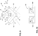
- the image sensor 22 may be positioned vertically above the primary mirror assembly 68 and the secondary mirror assembly 30, for example on the top wall 80.
- the primary mirror assembly 68 and the secondary mirror assembly 30 may be arranged along an x-axis of the cooking appliance 10. In this way, the field of view 24 of the imager assembly 18 may extend downward toward the cooking cavity 14 and include the primary mirror assembly 68.
- two separate image views are captured by the imager assembly 18.
- the image view of the first side of the food item 82 represented by the arrow A1 is included in the reflection zone 122 of the secondary mirror 32.
- the secondary mirror 32 reflects the image view represented by arrow A1 to the primary mirror 26 of the imager assembly 18, as represented by the arrow C1.
- the primary mirror 26 then reflects the image view, represented by arrow D1, to the image sensor 22.
- the image view of the second side of the food item 82 is included in the reflection zone 122 of the secondary mirror 34 and is reflected to the primary mirror 28, as represented by the arrow C2.
- the primary mirror 28 then reflects the image view to the image sensor 22, as represented by the arrow D2.
- the image views represented by the arrows D1, D2 may be directed through a light tunnel, optics, the lens 62, etc. to direct the image views to the image sensor 22 to be captured. While the image views are represented by arrows it is understood that the image views generally include a broader area within the cooking cavity 14 included in the reflection zones 122. The image views of the broader area are reflected to and captured by the imager assembly 18.
- the configuration of the monitoring system 44 is flexible.
- the position of the imager assembly 18, the primary mirror assembly 68, and/or the secondary mirror assembly 30 may be adjusted to any practicable position that allows the image views to be reflected to the image sensor 22.
- the secondary mirror assembly 30 may be arranged in the upper corners of the cooking cavity 14, the lower corners of the cooking cavity 14, the rear corners of the cooking cavity 14, and/or the front corners of the cooking cavity 14. Additionally or alternatively, the secondary mirror assembly 30 may be disposed on a y-axis within the cooking cavity 30. In additional non-limiting examples, the secondary mirror assembly 30 may be arranged on either of the sidewalls 84, 86 or the rear wall 88. Further, the secondary mirror assembly 30 may be arranged outside of the cooking cavity 14. The position of the secondary mirrors 32, 34, 126, 128 may depend on the position of the image sensor 22.
- the image sensor 22 may be arranged on the door 16 or within the cooking cavity 14.
- the secondary mirror assembly 30 is arranged to reflect multiple image views to the primary mirror assembly 68, which consequently reflects the image views to the image sensor 22.
- the image sensor 22 is positioned proximate to the primary mirrors 26, 28 that reflect the image views from two to four secondary mirrors 32, 34, 126, 128 to show two to four unique vantage points or perspectives of the cooking cavity 14.
- the imager assembly 18 is spaced from the heating element 78 to protect the image sensor 22 and other electronic components within the imager assembly 18 from overheating and, consequently, damage and failure. Additionally, when the imager assembly 18 is positioned on an outer portion of the cooking cavity 14, the lens 64 is more protected from food splatter.
- the imager assembly 18 generally includes a control unit 142 having a processor 144, a memory 146, and other control circuitry. Instructions or routines 148 are stored with the memory 146 and executable by the processor 144.
- the imager assembly 18 is configured to capture the image data from within the field of view 24.
- the field of view 24 includes the primary mirror assembly 68, which reflects the image views of the cooking cavity 14 from the secondary mirror assembly 30. The reflected image views are captured as the image data by the image sensor 22 and processed by the control unit 142.
- the control unit 142 may include at least one routine 148 directed to separating the image data into smaller standard-sized images.
- the image sensor 22 may be a wide-angle camera that captures wide-angled image data that is separated into about two standard images.
- the originally captured image data and/or the processed image data, collectively referred to herein as the image data, may then be communicated for additional processing and analyzing.
- the monitoring system 44 may include a controller 150 having a processor 152, a memory 154, and other control circuitry. Instructions or routines 156 are stored within the memory 154 and executable by the processor 152.
- the control circuitry may include communication circuitry 158 for bidirectional communication.
- the controller 150 is communicatively coupled with the imager assembly 18 to receive the image data.
- the controller 150 may further process the image data.
- the controller 150 is configured to analyze pixels of the image data received from the imager assembly 18.
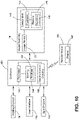
- the controller 150 may be configured to separate the image data into multiple sub-images 160, such as sub-images 160A, 160B illustrated in FIG. 11 .
- the sub-images 160A, 160B may correspond with the two standard images separated from the wide-angle image data by the imager assembly 18.
- the controller 150 may include at least one routine 156 that splits the image data into the sub-images 160 that correspond with the image views.
- the controller 150 may be configured to split the image data into two sub-images 160A, 160B.
- the sub-image 160A corresponds with the image view reflected from the secondary mirror 32
- the sub-image 160B corresponds with the image view reflected from the secondary mirror 34.
- the image data such as a single image capture by the image sensor 22, may be divided into the sub-images 160 based on the number of secondary mirrors 32, 34, 126, 128 in the secondary mirror assembly 30.
- the sub-images 160 collectively form the image data or capture obtained by the image sensor 22.
- the controller 150 is configured to divide the image data across the single image sensor 22. In certain aspects, the controller 150 may divide the image data into more than two sub-images 160. As an array resolution of the image sensor 22 is increased or a total pixel resolution in the sub-images 160 decreases, it is possible to split or divide the final image data into more than two sub-images 160. In such examples, the controller 150 includes at least one routine 156 to divide a final RGB array output into corresponding sections aligning each section with the image view reflected onto the image sensor 22. The controller 150 may store information related to which section of the image data aligns with the various image views of the secondary mirror assembly 30. Each image view reflected onto the image sensor 22 is a predefined size based on the secondary mirror assembly 30.
- the controller 150 may determine which pixels of the image correspond to which secondary mirror 32, 34, 126, 128 based on the location the pixels fall on the final image data. For example, with two image views, the pixels may be split in half and with four image views, the pixels may be split into quadrants. The controller 150 may selectively process and analyze a portion of the pixels based on the corresponding image view.
- the controller 150 is configured to analyze and overlay the sub-images 160.
- the controller 150 may determine an image quality of the sub-images 160 to determine which sub-images 160 are to be used in subsequent analysis. Different types of analysis may utilize a different number of sub-images 160.
- the monitoring system 44 may utilize an obstructed mirror contingency process for updating the image processing in real-time during a cooking process.
- the controller 150 is configured to determine the image quality of each sub-image 160 derived from or included in the image data.
- the controller 150 may compare the sub-images 160 to a predefined quality threshold.
- the image quality of the image data may be affected by obstructions on the secondary mirrors 32, 34, 126, 128, such as steam, grease, food splatter, etc.
- the low image quality produced by an obstructed mirror may affect machine learning of the monitoring system 44 as the obstructed image data becomes noise in the machine learning process.
- the contingency switching process between sub-images 160 allows the monitoring system 44 to proceed at or about near-full proficiency for the remainder of the cooking process until the user can remove the obstruction.
- This contingency may also be advantageous when a cooking receptacle (e.g., pan, etc.) obstructs at least one of the secondary mirrors 32, 34, 126, 128.
- the controller 150 may also be configured to notify the user that there is an obstruction affecting the secondary mirror assembly 30, as described further herein.
- different types of analysis with the image data may utilize a different number of sub-images 160.
- excess sub-images 160 may be obtained (e.g., more sub-images 160 than utilized by the selected analysis)
- the excess sub-images 160 may be substituted into the subsequent analysis when at least one sub-image 160 has an image quality below the predefined quality threshold.
- the obstructed sub-image 160 may be replaced by the controller 150 by a non-obstructed sub-image 160 to complete the analysis of the image data.
- the substitution or replacement may occur during the cooking process, such that the monitoring of the food item 82 during the cooking process is not substantially affected.
- the controller 150 may be configured to utilize rotated or reverse perspectives in each analysis without the different perspective from the substituted sub-image 160 without adversely affecting the analysis. In this way, the controller 150 is configured to recognize and analyze the image data from varying perspectives.
- the image data is analyzed with an image recognition routine 156.
- the controller 150 is configured to analyze the image data to determine a type of the food item 82 within the cooking cavity 14.
- the controller 150 may additionally or alternatively include a classification system for determining a food type of the food item 82 in the cooking cavity 14.
- the memory 152 may include stored information about types of food items 82.
- the controller 150 may include at least one routine 156 for analyzing the image data to determine a doneness of the food item 82 within the cooking cavity 14.
- the imager assembly 18 continually captures and communicates image data to the controller 150 during a cooking process.
- the controller 150 may monitor progressive doneness during the cooking process.
- the doneness may be determined by a brownness of the food item 82.
- the doneness may be determined by a change in size or shape of the food item 82.
- the use of the multiple image views allows each sub-image 160 to be a different perspective of the food item 82. The different perspectives may be combined to form a three-dimensional image through stereovision.
- the three-dimensional image may be monitored to determine if the food item 82 has changed in size or shape, including mass, depth, and volume. This may be advantageous for food items 82, such as bread, that rise during the cooking process.
- the multiple perspectives from the secondary mirror assembly 30 enable stereovision, which allows detection of states between rising and falling of certain food items 82.
- the controller 150 is configured to monitor the food item 82 during a cooking process.
- the controller 150 is communicatively coupled to the heating element 78 and may adjust the heating element 78 in response to the determined doneness of the food item 82.
- the doneness may be detected by, for example, browning of the food item 82 or a sufficient change in size or shape of the food item 82.
- the controller 150 may be configured to raise or lower a cooking temperature within the cooking cavity 14. Additionally or alternatively, the controller 150 may increase or decrease a cooking time for the food item 82. Automatic adjustments to the cooking temperature and the cooking time may be communicated to the user.
- the controller 150 may determine the cooking level 98 of the racks 100 in the cooking cavity 14 (e.g., a rack level). Specifically, the controller 150 may determine on which rack 100 the food item 82 is positioned and at which level that rack 100 is positioned. At least one secondary mirror 32, 34, 126, 128 may be placed at each cooking level 98 or at each grouping of cooking levels 98 to obtain multiple perspectives of the cooking levels 98. Alternatively, the secondary mirrors 32, 34, 126, 128 may be arranged at positions or angles such that each cooking level 98 is included in the reflection zone 122 of at least one secondary mirror 32, 34, 126, 128. The multiple views or perspectives of the cooking levels 98 may allow for the image data to be obtained in portions of the cooking cavity 14 that may be otherwise obscured by the food item 82 or the cooking receptacle.
- the controller 150 is configured to analyze the image data to determine the presence or absence of the food item 82 on each rack 100 within the cooking cavity 14. In this way, the controller 150 may determine an exact position of the food item 82, which may be advantageous for providing more precise cooking results. The controller 150 may adjust the cooking temperature, the cooking time, or other aspects of the cooking process based on the exact position of the food item 82 within the cooking cavity 14.
- the controller 150 may adjust which image data is processed based on the precise position of the food item 82.
- the image data obtained from the portion of the field of view 24 that includes the food item 82 is processed, while the image data without the food item 82 (e.g., empty pixels) may not be processed. This may be advantageous for improving machine learning of the monitoring system 44 as the empty pixels may be noise that affects the image data processing.
- the image sensor 22 may be adjustable to limit the empty pixels that are processed.
- the field of view 24 may also be adjustable to be broader, narrower, positionally shifted, or any combination thereof. In various examples, the image sensor 22 may be adjusted to change the scope of the field of view 24. It is contemplated that the lens 64 may be adjusted to change the sharpness and/or quality of the image data obtained by the image sensor 22.
- the controller 150 may determine whether the rack 100 is positioned at the correct cooking level 98 for the type of food item 82.
- the controller 150 may store an ideal cooking level 98 for various types of food items 82 and may compare the cooking level 98 determined from the image data with the ideal cooking level 98. For example, if the food item 82 is a baked good, a more central cooking level 98 may be advantageous. If the food item 82 (e.g., a baked good) is positioned too close to the heating element 78, the food item 82 may burn. In this way, the controller 150 may determine whether the food item 82 is positioned at the ideal or correct cooking level 98.
- the controller 150 may be configured to notify the user if the food item 82 is that an incorrect or less-than-ideal cooking level 98, as described further herein.
- the controller 150 may be configured to generate a notification 170 related to the image processing, information obtained from the image data, the cooking process, adjustments to the cooking process in response to the image data, or a combination thereof.
- the notification 170 may be displayed on a user interface 172 of the cooking appliance 10.
- the controller 150 may be communicatively coupled to a remote device 180 having a display 182.
- the controller 150 is configured to communicate the notification 170 to the remote device 180 through a wireless communication interface.
- the controller 150 may include the communication circuitry 158, which may be configured to communicate with the remote device 180 and/or remote servers (e.g., cloud servers, Internet-connected databases, computers, etc.) via the communication interface.
- the communication interface may be a wireless interface, such that the cooking appliance 10 and the remote device 180 are configured to emit wireless signals.
- the communication interface may correspond to a variety of communication protocols configured to distribute data among various electronic devices.
- the communication interface may include an IEEE 802.11 connection, an IEEE 802.15 connection, a Bluetooth ® connection, a Wi-Fi connection, a WiMAX connection, cellular signal, signal using shared wireless access protocol cord axis (SWAP-CA), or any other type of radiofrequency or wireless signal.
- An IEEE 802.15 connection includes any wireless personal area networks (WPAN), such as ZigBee ® , Z-wave ® , Bluetooth ® , UWB, and IrDA.
- WPAN wireless personal area networks
- the remote device 180 may be, for example, a phone, a tablet, a computer, a wearable device, or other electronic devices.
- the notification 170 may include a variety of information.
- the notification 170 may include a variety of information.
- the notification 170 may include cooking time information 190.
- the cooking time information 190 may include an initial cooking time, and a current remaining cooking time, and an updated cooking time.
- the cooking time information 190 may include a cooking time adjustment based on the automatic adjustment in response to the image data (such as the doneness) as described herein.
- the notification 170 may also include temperature information 192.
- the temperature information 192 may include an initial cooking temperature as well as a current cooking temperature.
- the current cooking temperature may be a result of an automatic adjustment based on the analysis of the image data as described herein.
- the notification 170 may include food type information 194.
- the food type information 194 may include specific food and/or a classification of the food item 82.
- the notification 170 may also include rack level information 196.
- the rack level information 196 may include the cooking level 98 at which the rack 100 with the food item 82 is positioned.
- the notification 170 may include a rack alert 198.
- the rack alert 198 may inform the user that the food item 82 is positioned at the incorrect cooking level 98 or a less-than-ideal cooking level 98 based on the food type information 194.
- the notification 170 may also include a cooking tip 200.
- the cooking tip 200 may include the ideal cooking level 98 for the food item 82 in the cooking cavity 14.
- the cooking tip 200 may also include other information for adjusting the cooking process (e.g., time, temperature, etc.) if the food item 82 is to stay at the current, incorrect cooking level 98.
- the cooking tip 200 may be advantageous for assisting the user during the cooking process to optimize the doneness of the food item 82.
- the notification 170 may also include an obstruction alert 204 if any portion of the secondary mirror assembly 30 is obstructed.
- the obstruction alert 204 may also include which secondary mirror 32, 34, 126, 128 is obstructed.
- the notification 170 may communicate actions to the user based on the type of obstruction. For example, if the controller 150 determines that food splatter is on one of the secondary mirrors 32, 34, 126, 128, the notification 170 may include a tip to clean the secondary mirror assembly 30.
- the notification 170 may include a tip that an alternate cooking receptacle be used in the future. Additionally or alternatively, the notification 170 may include a viewable image 206 of the food item 82 so the user may also monitor or confirm the doneness of the food item 82.
- the viewable image 206 may be one of the sub-images 160, the image data, the three-dimensional stereovision image, or a combination thereof.
- the notification 170 may be visual, audible, haptic, or a combination thereof without departing from the teachings herein.
- the monitoring system 44 is configured to actively monitor the food item 82 within the cooking cavity 14 during the cooking process.
- the monitoring system 44 may be activated based on a door triggering event. For example, when the door 16 is opened and then closed, the monitoring system 44 may be activated to determine whether the food item 82 is positioned within the cooking cavity 14. Additionally or alternatively, the monitoring system 44 may be activated when the heating element 78 is activated.
- the secondary mirrors 32, 34, 126, 128 are arranged around the cooking cavity 14 to reflect various image views to the primary mirror assembly 68. Each secondary mirror 32, 34, 126, 128 reflects a separate and unique image view of the cooking cavity 14 to provide multiple perspectives to the image sensor 22. The image views are reflected from the secondary mirror assembly 30 to the primary mirror assembly 68, which then reflects the image views to the image sensor 22.
- the image sensor 22 captures the image data, including the multiple image views, and communicates the image data to the controller 150 for use by the cooking appliance 10.
- the image data may be analyzed by the controller 150 and utilized to control the operation of the cooking appliance 10, to control the cooking process, and to alert the user about adjustments and cooking tips as described herein.
- the monitoring system 44 may monitor the progress of the food item 82 throughout the cooking process and automatically make adjustments based on information obtained from the image data.
- the monitoring system 44 may provide a flexible implementation in the cooking appliance 10.
- the imager assembly 18 may be spaced from the heating element 78 and utilize the primary mirror assembly 68 and the secondary mirror assembly 30 to obtain multiple views of the cooking cavity 14.
- the imager assembly 18 may be spaced from the heating element 78 to increase the longevity of the image sensor 22, as well as reduce splatter on the lens 64.
- the monitoring system 44 may reduce manufacturing costs by reducing additional venting used in convention systems for cooling cameras and other image devices.
- the monitoring system 44 uses stereovision with the single image sensor 22 and multiple different views of the cooking cavity 14 from various mirrors.
- Stereovision may be advantageous for providing a three-dimensional image of the cooking cavity 14, which allows for depth, volume, and mass determinations of the food item 82 within the cooking cavity 14.
- the secondary mirror assembly 30 may include between about two mirrors and about four mirrors within or adjacent to the cooking cavity 14 to provide multiple image views.
- the mirrors within the monitoring system 44 may also allow monitoring of an increased area within the cooking cavity 14.
- the monitoring system 44 is configured to determine a variety of information about the food item 82 using the image data received by the imager assembly 18.
- the controller 150 is configured to determine the type of food item 82 within the cooking cavity 14, the doneness of the food item 82, and the cooking level 98 of the rack 100 on which the food item 82 is positioned. Further, the controller 150 may use the various determinations to adjust the operation of the cooking appliance 10. For example, the monitoring system 44 may adjust the cooking temperature or the cooking time based on at least the doneness determined by the controller 150. Additionally, the monitoring system 44 may notify the user that the food item 82 is positioned at the improper cooking levels 98 based on the type of food.
- the monitoring system 44 may update in real-time to disregard image views from obstructed secondary mirrors 32, 34, 126, 128 and substitute non-obstructed sub-images 160.
- the real-time adjustment may avoid occlusions and obstructions within the image data. Additional benefits or advantages will be realized and/or achieved.
- the device disclosed herein is further summarized in the following paragraphs and is further characterized by combinations of any and all of the various aspects described therein.
- a cooking appliance includes a body defining a cooking cavity.
- a door is rotatably coupled to the body.
- An imager assembly is coupled to an interior surface of the door.
- the imager assembly includes an image sensor configured to obtain image data within a field of view, a first primary mirror positioned at a first angle proximate to the image sensor and within the field of view, and a second primary mirror positioned at a second angle proximate to the image sensor and within the field of view.
- a secondary mirror assembly includes multiple secondary mirrors coupled to the body within the cooking cavity. The secondary mirrors reflect image views within the cooking cavity to the first primary mirror and the second primary mirror, which reflects the image views to the image sensor to be captured as the image data.
- a controller is operably coupled to an imager assembly to receive image data.
- the controller is configured to separate the image data into multiple sub-images for image recognition processing. Each sub-image corresponds with one of the secondary mirrors.
- multiple secondary mirrors include a first secondary mirror disposed in a first rear corner within a cooking cavity and a second secondary mirror disposed within a second rear corner of the cooking cavity.
- multiple secondary mirrors include a third secondary mirror disposed in a third rear corner within a cooking cavity and a fourth secondary mirror disposed within a fourth rear corner of the cooking cavity.
- an imager assembly includes a support structure defining an interior cavity.
- An image sensor is disposed on a first side of the interior cavity and a first primary mirror and a second primary mirror are disposed on a second side of the interior cavity.
- a controller is operably coupled to an imager assembly.
- the controller is configured to determine at least one of a food type, a food doneness, a cooking time, a rack level, and an obstruction on at least one of multiple secondary mirrors utilizing image data.
- a stereovision monitoring system for a cooking appliance includes a body defining a cooking cavity.
- a door is rotatably coupled to the body.
- An imager assembly is coupled to one of the door and the body.
- the imager assembly includes a support feature that defines an interior cavity, an imager coupled to the support feature on a first side of the interior cavity, and at least one primary mirror coupled to the support feature on a second side of the interior cavity.
- At least one secondary mirror is disposed within the cooking cavity.
- the at least one secondary mirror reflects at least one image view of the cooking cavity to the at least one primary mirror.
- the at least one primary mirror reflects the at least one image view to the imager to be captured as image data.
- a controller is operably coupled to the imager assembly to receive the image data.
- At least one primary mirror includes a first primary mirror and a second primary mirror.
- At least one secondary mirror includes a first secondary mirror and a second secondary mirror.
- At least one image view includes a first image view and a second image view.
- a first secondary mirror reflects the first image view to a first primary mirror and a second secondary mirror reflects the second image view to a second primary mirror.
- a controller is configured to separate image data into multiple sub-images that correspond with a first image view and a second image view for image recognition processing.
- a rack is disposed within a cooking cavity.
- a controller is configured to process image data to determine at least one of a rack level within the cooking cavity and if a food item is disposed on the rack.
- a controller is configured to process image data to determine a type of food.
- the controller is configured to generate a notification if a rack is disposed at an incorrect cooking level based on the type of food.
- a controller is configured to determine whether at least one secondary mirror is obstructed based on image data that corresponds with at least one image view reflected from the at least one secondary mirror.
- a heating element is disposed within a cooking cavity and is operably coupled to a controller.
- the controller is configured to adjust a cooking temperature produced by the heating element in response to image data.
- an image system for a cooking appliance includes a support structure.
- An imager is coupled to the support structure.
- the imager is configured to obtain image data within a field of view.
- a primary mirror assembly is coupled to the support structure proximate to the imager.
- the primary mirror assembly includes a first primary mirror, which is disposed at a first angle within the field of view of the imager, and a second primary mirror, which is disposed at a second angle within the field of view of the imager.
- a secondary mirror assembly is configured to reflect image views of the cooking cavity to the primary mirror assembly. The image views are reflected by the primary mirror assembly to the imager to be captured as the image data.
- a controller is configured to receive the image data from the imager.
- a secondary mirror assembly includes a secondary mirror disposed in at least one front corner of a cooking cavity.
- a controller is configured to generate a notification to be communicated to a remote device.
- a notification includes at least one of a correct cooking level, a type of food within a cooking cavity, an updated cooking time, and a cooking temperature.
- a secondary mirror assembly includes multiple secondary mirrors.
- a controller is configured to separate the image data into multiple sub-images that correspond with the multiple secondary mirrors.
- a controller is configured to analyze the image data to determine an image quality of each sub-image. If the image quality of at least one of the sub-images is below a predefined quality threshold, the controller is configured to determine that a corresponding secondary mirror is obstructed and consequently configured to utilize a different sub-image for subsequent image processing.
Landscapes
- Engineering & Computer Science (AREA)
- Food Science & Technology (AREA)
- Multimedia (AREA)
- Physics & Mathematics (AREA)
- General Physics & Mathematics (AREA)
- Theoretical Computer Science (AREA)
- Signal Processing (AREA)
- Chemical & Material Sciences (AREA)
- Combustion & Propulsion (AREA)
- Mechanical Engineering (AREA)
- General Engineering & Computer Science (AREA)
- Electric Ovens (AREA)
Abstract
Description
- The present disclosure generally relates to a monitoring system, and more specifically, to a stereovision monitoring system for a cooking appliance.
- According to one aspect of the present disclosure, a cooking appliance includes a body defining a cooking cavity. A door is rotatably coupled to the body. An imager assembly is coupled to an interior surface of the door. The imager assembly includes an image sensor configured to obtain image data within a field of view, a first primary mirror positioned at a first angle proximate to the image sensor and within the field of view, and a second primary mirror positioned at a second angle proximate to the image sensor and within the field of view. A secondary mirror assembly includes multiple secondary mirrors coupled to the body within the cooking cavity. The secondary mirrors reflect image views within the cooking cavity to the first primary mirror and the second primary mirror, which reflects the image views to the image sensor to be captured as the image data.
- According to another aspect of the present disclosure, a stereovision monitoring system for a cooking appliance includes a body defining a cooking cavity. A door is rotatably coupled to the body. An imager assembly is coupled to one of the door and the body. The imager assembly includes a support feature that defines an interior cavity, an imager coupled to the support feature on a first side of the interior cavity, and at least one primary mirror coupled to the support feature on a second side of the interior cavity. At least one secondary mirror is disposed within the cooking cavity. The at least one secondary mirror reflects at least one image view of the cooking cavity to the at least one primary mirror. The at least one primary mirror reflects the at least one image view to the imager to be captured as image data. A controller is operably coupled to the imager assembly to receive the image data.
- According to yet another aspect of the present disclosure, an image system for a cooking appliance includes a support structure. An imager is coupled to the support structure. The imager is configured to obtain image data within a field of view. A primary mirror assembly is coupled to the support structure proximate to the imager. The primary mirror assembly includes a first primary mirror, which is disposed at a first angle within the field of view of the imager, and a second primary mirror, which is disposed at a second angle within the field of view of the imager. A secondary mirror assembly is configured to reflect image views of the cooking cavity to the primary mirror assembly. The image views are reflected by the primary mirror assembly to the imager to be captured as the image data. A controller is configured to receive the image data from the imager.
- These and other features, advantages, and objects of the present disclosure will be further understood and appreciated by those skilled in the art by reference to the following specification, claims, and appended drawings.
- In the drawings:
-
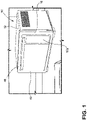
FIG. 1 is a front perspective view of a cooking appliance, according to the present disclosure; -
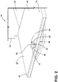
FIG. 2 is a front perspective view of an imager assembly of a monitoring system coupled to an appliance door, according to the present disclosure; -
FIG. 3 is a side perspective view of an imager assembly for a cooking appliance monitoring system, according to the present disclosure; -
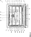
FIG. 4 is a front elevational view of a cooking cavity having two secondary mirrors arranged in an upper corner, according to the present disclosure; -
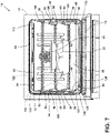
FIG. 5 is a front elevational view of the cooking cavity ofFIG. 4 illustrating image views represented by arrows A1, A2 and arrows B1, B2, within reflection zones of the secondary mirrors being reflected from the secondary mirrors to an imager assembly, as represented by arrows C1, C2, according to the present disclosure; -
FIG. 6 is a front elevational view of a cooking cavity with four secondary mirrors arranged in upper and lower corners, according to the present disclosure; -
FIG. 7 is a front elevational view of a cooking cavity with four secondary mirrors arranged in upper and lower corners on a single side of the cooking cavity opposite of an imager assembly, according to the present disclosure; -
FIG. 8 is a schematic diagram of a monitoring system with secondary mirrors disposed proximate to windows for reflecting image views represented by arrows A1, A2 from the secondary mirrors to an imager assembly, as represented by arrows C1, C2 and arrows D1, D2, according to the present disclosure; -
FIG. 9 is a schematic diagram of a monitoring system with an imager assembly disposed vertically above mirrors with image views represented by arrows A1, A2 being directed to the mirrors and subsequently reflected to the imager assembly, as represented by arrows C1, C2 and arrows D1, D2, according to the present disclosure; -
FIG. 10 is a block diagram of a monitoring system for a cooking appliance, according to the present disclosure; -
FIG. 11 is representative of two sub-images derived from image data captured in a cooking cavity by a stereovision monitoring system, according to the present disclosure; -
FIG. 12 is representative of a notification from a monitoring system displayed on a user interface of a cooking appliance, according to the present disclosure; and -
FIG. 13 is representative of a notification from a monitoring system displayed on a remote device, according to the present disclosure. - The components in the figures are not necessarily to scale, emphasis instead being placed upon illustrating the principles described herein.
- The present illustrated embodiments reside primarily in combinations of method steps and apparatus components related to a stereovision monitoring system for a cooking appliance. Accordingly, the apparatus components and method steps have been represented, where appropriate, by conventional symbols in the drawings, showing only those specific details that are pertinent to understanding the embodiments of the present disclosure so as not to obscure the disclosure with details that will be readily apparent to those of ordinary skill in the art having the benefit of the description herein. Further, like numerals in the description and drawings represent like elements.
- For purposes of description herein, the terms "upper," "lower," "right," "left," "rear," "front," "vertical," "horizontal," and derivatives thereof shall relate to the disclosure as oriented in
FIG. 1 . Unless stated otherwise, the term "front" shall refer to the surface of the element closer to an intended viewer, and the term "rear" shall refer to the surface of the element further from the intended viewer. However, it is to be understood that the disclosure may assume various alternative orientations, except where expressly specified to the contrary. It is also to be understood that the specific devices and processes illustrated in the attached drawings, and described in the following specification are simply exemplary embodiments of the inventive concepts defined in the appended claims. Hence, specific dimensions and other physical characteristics relating to the embodiments disclosed herein are not to be considered as limiting, unless the claims expressly state otherwise. - The terms "including," "comprises," "comprising," or any other variation thereof, are intended to cover a non-exclusive inclusion, such that a process, method, article, or apparatus that comprises a list of elements does not include only those elements but may include other elements not expressly listed or inherent to such process, method, article, or apparatus. An element preceded by "comprises a . . . " does not, without more constraints, preclude the existence of additional identical elements in the process, method, article, or apparatus that comprises the element.
- Referring to
FIGS. 1-13 ,reference numeral 10 generally designates a cooking appliance that has abody 12 that defines acooking cavity 14. Adoor 16 is rotatably coupled to thebody 12. Animager assembly 18 is coupled to an interior surface 20 of thedoor 16. Theimager assembly 18 includes an imager orimage sensor 22 configured to obtain image data within a field ofview 24. Theimager assembly 18 also includes a firstprimary mirror 26 positioned at a first angle proximate to theimage sensor 22 and within the field ofview 24, and a secondprimary mirror 28 positioned at a second angle proximate to theimage sensor 22 and within the field ofview 24. Asecondary mirror assembly 30 includes multiplesecondary mirrors body 12 within thecooking cavity 14. Thesecondary mirrors cooking cavity 14 to the firstprimary mirror 26 and the secondprimary mirror 28 which reflect the image views to theimage sensor 22 to be captured as the image data. - Referring to
FIGS. 1 and2 , thecooking appliance 10 includes thebody 12 with thedoor 16 rotatably coupled to thebody 12. Thedoor 16 is configured to rotate between a closedposition 40 and an openedposition 42 to selectively allow access to thecooking cavity 14. Thecooking appliance 10 is illustrated as a single-cavity, countertop appliance. It is contemplated that thecooking appliance 10 may be a mounted appliance, a slide-in appliance, a freestanding appliance, or a countertop appliance. Additionally, thecooking appliance 10 may include thesingle cooking cavity 14 ormultiple cooking cavities 14. Additionally or alternatively, thecooking appliance 10 may be, for example, a microwave oven, a traditional oven, or a multifunction appliance that performs oven-like functions (e.g., roast, bake, etc.) as well as other functions. - Referring to
FIG. 2 , as well asFIG. 3 , thecooking appliance 10 includes amonitoring system 44 for monitoring thecooking cavity 14. Themonitoring system 44 is generally an image-basedmonitoring system 44. In certain aspects, themonitoring system 44 is astereovision monitoring system 44 that utilizes thesingle image sensor 22. Themonitoring system 44 includes theimage sensor 22 to obtain the image data within the field ofview 24. The field ofview 24 of theimage sensor 22 generally extends toward and at least partially into thecooking cavity 14. - The
image sensor 22 may be any area type imager, such as a charge coupled device (CCD) or a complementary metal oxide semiconductor (CMOS) imager, or any type of color or black-and-white camera. In certain aspects, theimage sensor 22 is a wide-angle camera configured to obtain the image data within the field ofview 24 in thecooking cavity 14. As discussed further herein, the image data includes multiple image views from multiple visual angles from within thecooking cavity 14. It is contemplated that the image data may include at least one of a picture, a video, real-time streaming of image data, other transmissions of image data, or combinations thereof without departing from the teachings herein. Thestereovision monitoring system 44 provides the multiple image views using thesingle image sensor 22. - In the example illustrated in
FIG. 2 , theimager assembly 18 is coupled to the interior surface 20 of thedoor 16. Theimager assembly 18 is centrally located proximate to anupper edge 48 of thedoor 16 but may be coupled to any practicable position on thedoor 16. Theimager assembly 18 includes asupport structure 50 that couples to thedoor 16. Thesupport structure 50 includes abase housing 52 and asupport feature 54. Thebase housing 52 is generally disposed within the interior of thedoor 16, while thesupport feature 54 extends through and away from the interior surface 20 of thedoor 16. In certain aspects, thedoor 16 may include multiple glass panels. Theimage sensor 22 may be disposed between two adjacent layers of glass panels on thedoor 16. - The
support feature 54 may have threewalls FIG. 2 , or may have twowalls FIG. 3 . In the example illustrated inFIG. 2 , twowalls base housing 52 and are generally parallel. Thewall 58 extends between the twowalls base housing 52. Thewall 58 is positioned directly between theimage sensor 22 and thecooking cavity 14. When thedoor 16 is in the closed position 40 (FIG. 1 ), thewall 56 is an upper wall, thewall 58 is an inner wall, and, if included, thewall 60 is a lower wall. - The
walls base housing 52 define aninterior cavity 62 therebetween. In various examples, thesupport feature 54 includes thewalls third wall 60, as illustrated inFIG. 3 . In such configurations, thesupport feature 54 has an L-shape extending away from and then parallel to thebase housing 52. Alens 64 is coupled to thebase housing 52 on afirst side 66 of theinterior cavity 62 and aligns with theimage sensor 22 disposed within thebase housing 52. Aprimary mirror assembly 68, including the first and second primary mirrors 26, 28, is coupled to thewall 58 on asecond side 70 of theinterior cavity 62. Theprimary mirror assembly 68 is disposed proximate to thelens 64 and within the field ofview 24 of theimage sensor 22. Theinterior cavity 62 is a sufficient size to house thelens 64 and theprimary mirror assembly 68 spaced from one another. - As previously stated, the
primary mirror assembly 68 includes the first and second primary mirrors 26, 28. The first and second primary mirrors 26, 28 are each coupled to thewall 58 and extend into theinterior cavity 62. The primary mirrors 26, 28 may not extend out of theinterior cavity 62. Additionally or alternatively, the firstprimary mirror 26 is disposed at a first angle α and the secondprimary mirror 28 is disposed on a second angle β relative to thewall 58. Generally, the first and second angles α, β are mirror images of one another. The primary mirrors 26, 28 extend from thewall 58 and toward one another. In various aspects, the primary mirrors 26, 28 are coupled to or abut one another proximate to thelens 64. The specific angles α, β of the primary mirrors 26, 28 may be adjusted to reflect the image views to theimage sensor 22 to be captured as the image data, as described further herein. It is contemplated that the field ofview 24 is split and diverted generally parallel to the interior surface 20 of thedoor 16 to thesecondary mirror assembly 30 by theprimary mirror assembly 68. Thesecondary mirror assembly 30 is oriented to direct light towards thecooking cavity 14. - When the
imager assembly 18 is coupled to thedoor 16, theprimary mirror assembly 68 is oriented laterally. In such configurations, thewall 56 is an upper wall and thewall 60, if included, is a lower wall, leaving open lateral sides for theprimary mirror assembly 68 to reflect the image views. Further, in such configurations, the firstprimary mirror 26 is oriented in a first lateral direction (e.g., right) and the secondprimary mirror 28 is oriented in a second lateral direction (e.g., left). - Referring to
FIG. 4 , thecooking appliance 10 includes aheating element 78 generally coupled in atop wall 80 that defines thecooking cavity 14. It is contemplated that theheating element 78 may be disposed in additional or alternative locations without departing from the teachings herein. Theheating element 78 is configured to produce or generate heat within thecooking cavity 14 to cookfood items 82 placed in thecooking cavity 14. Thecooking cavity 14 is generally defined by multiple walls including twosidewalls rear wall 88, thetop wall 80, and abottom wall 90. - The
sidewalls supports 96 arranged to definemultiple cooking levels 98. In the illustrated configuration ofFIG. 4 , thesupports 96 defined fivecooking levels 98A-98F, which are generally referred to herein as thecooking levels 98.Multiple racks 100 are illustrated within thecooking cavity 14 on thesupports 96. At any given time, one ormore racks 100 may be disposed within thecooking cavity 14 at thevarious cooking levels 98. Thefood items 82 are supported on theracks 100. The user may adjust the number and position (e.g., the cooking level 98) of eachrack 100. - The
cooking appliance 10 includes one or morelight sources 120 operably coupled with thecooking cavity 14. Generally, thelight sources 120 emit light into thecooking cavity 14. Thelight sources 120 generally control an intensity and color of light within thecooking cavity 14. Thelight sources 120 may remain activated (e.g., emitting light) when theimager assembly 18 is activated to illuminate thecooking cavity 14 and thereby allowing theimager assembly 18 to obtain the image data. As theimager assembly 18 may be utilized to monitor an entire cooking process, or a substantial portion thereof, thelight source 120 may also be activated during the entire or a substantial portion of the cooking process. - In various examples, the
light source 120 may emit visible light that has a wavelength in a range of from about 380 nm to about 740 nm, or a mix of wavelengths in this range. Thelight source 120 may include any form of light source, for example, fluorescent lighting, light emitting diodes (LEDs), organic LEDs (OLEDs), polymer LEDs (PLEDs), laser diodes, quantum dot LEDs (QD-LEDs), solid-state lighting, a hybrid, and/or any other similar device. Any other form of lighting may be utilized within thecooking appliance 10 without departing from the teachings herein. Further, various types of LEDs are suitable for use as thelight source 120, including, but not limited to, top-emitting LEDs, side-emitting LEDs, and others. According to various examples, multicolored light sources, such as Red, Green, and Blue (RGB) LEDs that employ red, green, and blue LED packaging may be used to generate various desired colors of light output from a single light source, according to known light color mixing techniques. Moreover, thelight source 120 may be configured as a single light source, or alternatively, as more than one light source that can be selectively and independently controlled. Moreover, thelight sources 120 may emit any wavelength of light for illuminating thecooking cavity 14 to obtain the image data without departing from the teachings herein. - Referring still to
FIG. 4 , as well as toFIG. 5 , thesecondary mirror assembly 30 is disposed within thecooking cavity 14. In the illustrated configuration, twosecondary mirrors secondary mirror assembly 30. The firstsecondary mirror 32 is disposed in an upperrear corner 110 within thecooking cavity 14, and the secondsecondary mirror 34 is disposed in an opposing upperrear corner 112. The secondary mirrors 32, 34 are oriented at predefined angles for reflecting the image views of thefood items 82 from different visual angles to theimager assembly 18. - Each of the
secondary mirrors reflection zone 122 within thecooking cavity 14. Thereflection zone 122 includes an area within thecooking cavity 14 that is reflected by eachsecondary mirror FIG. 5 , with the twosecondary mirrors secondary mirror assembly 30 has tworeflection zones 122. Thereflection zones 122 are oriented at different or opposing angles within thecooking cavity 14, with eachreflection zone 122 corresponding with one of thesecondary mirrors food item 82 is included in thereflection zone 122 of thesecondary mirror 32 and a second opposing side of thefood item 82 is included in thereflection zone 122 corresponding to thesecondary mirror 34. Additionally or alternatively, thefood item 82 in thevarious reflection zones 122 reflects light toward thesecondary mirror assembly 30. The secondary mirrors 32, 34 may be disposed at angles that are mirror images of one another, or alternative may be disposed at different angles depending on the location of theimager assembly 18. - The image view of the first side of the two
food items 82 is represented by arrow A1 and arrow B1, respectively. The arrows A1, B1 represent the image view within thereflection zone 122 of thesecondary mirror 110. Thesecondary mirror 32 then reflects the image views A1, B1 to theimager assembly 18, represented by arrow C1. The image view represented by the arrow C1 is captured by theimager assembly 18. Similarly, the image view of the second side of the twofood items 82 is represented by arrow A2 and arrow B2, respectively. The image views represented by the arrows A2, B2 are then reflected by thesecondary mirror 34 to theimager assembly 18, as represented by arrow C2. In this way, the reflected image views represented by the arrows C1, C2 may be captured simultaneously by theimager assembly 18 to capture different image views (e.g., A1, B1 and A2, B2) within thecooking cavity 14. - Referring to
FIG. 6 , an additional alternative configuration of thesecondary mirror assembly 30 is illustrated. As illustrated inFIG. 6 , thesecondary mirror assembly 30 includes foursecondary mirrors rear corners secondary mirror 126 is disposed in a lowerrear corner 130, and thesecondary mirror 128 is disposed in an opposing lowerrear corner 132. In this way, eachcorner rear wall 88 includes onesecondary mirror secondary mirrors secondary mirrors secondary mirrors secondary mirrors 126, 128 (e.g., over a y-axis). - Each of the
secondary mirrors imager assembly 18. In this way, four separate image views corresponding with different visual angles may be reflected to theimager assembly 18 to be captured in the image data. The image views in the illustrated configuration may include a first side upper view, a second side upper view, a first side lower view, and a second side lower view. However, the different image views may be adjusted based on the positioning and angle of thesecondary mirror assembly 30. - Referring again to
FIGS. 2-6 , the position and angles of thesecondary mirror assembly 30 may be determined by the relationship between theimage sensor 22 and thesecondary mirrors monitoring system 44 include a focal length of theimage sensor 22, the field ofview 24 of theimage sensor 22, x- and y-dimensions of theimage sensor 22, and pixels in the image data. The secondary mirrors 32, 34, 126, 128 may be any practicable size based on theimage sensor 22. For example, when theimager assembly 18 is coupled to a central location on thedoor 16, the position of thesecondary mirrors 

cooking cavity 14, Voffset is a distance between thetop wall 80 of thecooking cavity 14 and theimage sensor 22, and hoffset is a distance a center of the primary mirrors 26, 28 extend fromdoor 16. - Referring to
FIG. 7 , an additional or alternative configuration of themonitoring system 44 is illustrated. In the illustrated example, theimager assembly 18 is coupled to thesidewall 86 of thecooking appliance 10 that defines thecooking cavity 14. Theimager assembly 18 may extend partially into thecooking cavity 14, as illustrated, or may be disposed behind thesidewall 86 and aligned with a transparent portion or window of thesidewall 86 to obtain the image data from thecooking cavity 14. In the configuration illustrated inFIG. 7 , foursecondary mirrors cooking cavity 14. Thesecondary mirror 32 is disposed in an upperfront corner 134, thesecondary mirror 34 is disposed in the upperrear corner 110, thesecondary mirror 126 is disposed in a lowerfront corner 136, and thesecondary mirror 128 the disposed in a lowerfront corner 138. Each of thesecondary mirrors 32 reflects the image view from the correspondingreflection zone 122 to theimager assembly 18. In the illustrated configuration, the image views may include a combination of upper and lower, as well as front and rear image views. - Referring to
FIG. 8 , a schematic diagram of an additional or alternative configuration of themonitoring system 44 is illustrated. The secondary mirrors 32, 34 may be disposed outside of thecooking cavity 14 and be aligned withwindows 140 or other transparent portions that provide a view into thecooking cavity 14. The secondary mirrors 32, 34 and theimager assembly 18 with theprimary mirror assembly 68 are disposed on the same side of thecooking cavity 14. For example, each of theimager assembly 18 and thesecondary mirrors 32 may be coupled to thedoor 16 or alternatively, thesecondary mirrors imager assembly 18 may be coupled to thedoor 16. When thesecondary mirrors body 12, thesecondary mirrors cooking cavity 14 and separated from thecooking cavity 14 by thewindows 140. Thewindows 140 may act to form a periscope view for thesecondary mirrors secondary mirrors food item 82 within thecooking cavity 14 are reflected from thesecondary mirrors imager assembly 18. - Referring to
FIG. 9 , a schematic diagram of an additional alternative configuration of themonitoring system 44 is illustrated. Themonitoring system 44 includes four total mirrors, including twosecondary mirrors primary mirrors corresponding reflection zones 122 oriented toward thefood item 82 disposed within thecooking cavity 14. Two opposing image views are reflected from thereflection zones 122 by thesecondary mirrors primary mirror assembly 68 may be included in or separate from theimager assembly 18 and arranged to reflect the image views to theimage sensor 22 to be captured as the image data. - In the illustrated example, the
image sensor 22 may be positioned vertically above theprimary mirror assembly 68 and thesecondary mirror assembly 30, for example on thetop wall 80. Theprimary mirror assembly 68 and thesecondary mirror assembly 30 may be arranged along an x-axis of thecooking appliance 10. In this way, the field ofview 24 of theimager assembly 18 may extend downward toward thecooking cavity 14 and include theprimary mirror assembly 68. - Referring again to
FIG. 8 and still toFIG. 9 , two separate image views, represented by the arrows A1, A2, are captured by theimager assembly 18. The image view of the first side of thefood item 82, represented by the arrow A1, is included in thereflection zone 122 of thesecondary mirror 32. Thesecondary mirror 32 reflects the image view represented by arrow A1 to theprimary mirror 26 of theimager assembly 18, as represented by the arrow C1. Theprimary mirror 26 then reflects the image view, represented by arrow D1, to theimage sensor 22. - Similarly, the image view of the second side of the
food item 82, represented by the arrow A2, is included in thereflection zone 122 of thesecondary mirror 34 and is reflected to theprimary mirror 28, as represented by the arrow C2. Theprimary mirror 28 then reflects the image view to theimage sensor 22, as represented by the arrow D2. The image views represented by the arrows D1, D2 may be directed through a light tunnel, optics, thelens 62, etc. to direct the image views to theimage sensor 22 to be captured. While the image views are represented by arrows it is understood that the image views generally include a broader area within thecooking cavity 14 included in thereflection zones 122. The image views of the broader area are reflected to and captured by theimager assembly 18. - Referring to
FIGS. 2-9 , the configuration of themonitoring system 44 is flexible. The position of theimager assembly 18, theprimary mirror assembly 68, and/or thesecondary mirror assembly 30 may be adjusted to any practicable position that allows the image views to be reflected to theimage sensor 22. Thesecondary mirror assembly 30 may be arranged in the upper corners of thecooking cavity 14, the lower corners of thecooking cavity 14, the rear corners of thecooking cavity 14, and/or the front corners of thecooking cavity 14. Additionally or alternatively, thesecondary mirror assembly 30 may be disposed on a y-axis within thecooking cavity 30. In additional non-limiting examples, thesecondary mirror assembly 30 may be arranged on either of thesidewalls rear wall 88. Further, thesecondary mirror assembly 30 may be arranged outside of thecooking cavity 14. The position of thesecondary mirrors image sensor 22. - The
image sensor 22 may be arranged on thedoor 16 or within thecooking cavity 14. Thesecondary mirror assembly 30 is arranged to reflect multiple image views to theprimary mirror assembly 68, which consequently reflects the image views to theimage sensor 22. Theimage sensor 22 is positioned proximate to the primary mirrors 26, 28 that reflect the image views from two to foursecondary mirrors cooking cavity 14. Theimager assembly 18 is spaced from theheating element 78 to protect theimage sensor 22 and other electronic components within theimager assembly 18 from overheating and, consequently, damage and failure. Additionally, when theimager assembly 18 is positioned on an outer portion of thecooking cavity 14, thelens 64 is more protected from food splatter. - Referring to
FIG. 10 , as well as toFIGS. 1-9 , theimager assembly 18 generally includes acontrol unit 142 having aprocessor 144, amemory 146, and other control circuitry. Instructions orroutines 148 are stored with thememory 146 and executable by theprocessor 144. Theimager assembly 18 is configured to capture the image data from within the field ofview 24. The field ofview 24 includes theprimary mirror assembly 68, which reflects the image views of thecooking cavity 14 from thesecondary mirror assembly 30. The reflected image views are captured as the image data by theimage sensor 22 and processed by thecontrol unit 142. In certain aspects, thecontrol unit 142 may include at least one routine 148 directed to separating the image data into smaller standard-sized images. In such configurations, theimage sensor 22 may be a wide-angle camera that captures wide-angled image data that is separated into about two standard images. The originally captured image data and/or the processed image data, collectively referred to herein as the image data, may then be communicated for additional processing and analyzing. - The
monitoring system 44 may include acontroller 150 having aprocessor 152, amemory 154, and other control circuitry. Instructions orroutines 156 are stored within thememory 154 and executable by theprocessor 152. The control circuitry may includecommunication circuitry 158 for bidirectional communication. - The
controller 150 is communicatively coupled with theimager assembly 18 to receive the image data. Thecontroller 150 may further process the image data. In various examples, thecontroller 150 is configured to analyze pixels of the image data received from theimager assembly 18. Thecontroller 150 may be configured to separate the image data intomultiple sub-images 160, such as sub-images 160A, 160B illustrated inFIG. 11 . The sub-images 160A, 160B may correspond with the two standard images separated from the wide-angle image data by theimager assembly 18. - The
controller 150 may include at least one routine 156 that splits the image data into thesub-images 160 that correspond with the image views. For example, when thesecondary mirror assembly 30 includes the twosecondary mirrors controller 150 may be configured to split the image data into twosub-images secondary mirror 32 and the sub-image 160B corresponds with the image view reflected from thesecondary mirror 34. The image data, such as a single image capture by theimage sensor 22, may be divided into thesub-images 160 based on the number ofsecondary mirrors secondary mirror assembly 30. Generally, thesub-images 160 collectively form the image data or capture obtained by theimage sensor 22. - The
controller 150 is configured to divide the image data across thesingle image sensor 22. In certain aspects, thecontroller 150 may divide the image data into more than two sub-images 160. As an array resolution of theimage sensor 22 is increased or a total pixel resolution in thesub-images 160 decreases, it is possible to split or divide the final image data into more than two sub-images 160. In such examples, thecontroller 150 includes at least one routine 156 to divide a final RGB array output into corresponding sections aligning each section with the image view reflected onto theimage sensor 22. Thecontroller 150 may store information related to which section of the image data aligns with the various image views of thesecondary mirror assembly 30. Each image view reflected onto theimage sensor 22 is a predefined size based on thesecondary mirror assembly 30. Based on the predefined size, thecontroller 150 may determine which pixels of the image correspond to whichsecondary mirror controller 150 may selectively process and analyze a portion of the pixels based on the corresponding image view. - Referring still to
FIG. 10 , thecontroller 150 is configured to analyze and overlay the sub-images 160. Thecontroller 150 may determine an image quality of thesub-images 160 to determine which sub-images 160 are to be used in subsequent analysis. Different types of analysis may utilize a different number ofsub-images 160. - In various examples, the
monitoring system 44 may utilize an obstructed mirror contingency process for updating the image processing in real-time during a cooking process. Thecontroller 150 is configured to determine the image quality of each sub-image 160 derived from or included in the image data. Thecontroller 150 may compare thesub-images 160 to a predefined quality threshold. The image quality of the image data may be affected by obstructions on thesecondary mirrors monitoring system 44 as the obstructed image data becomes noise in the machine learning process. The contingency switching process betweensub-images 160 allows themonitoring system 44 to proceed at or about near-full proficiency for the remainder of the cooking process until the user can remove the obstruction. This contingency may also be advantageous when a cooking receptacle (e.g., pan, etc.) obstructs at least one of thesecondary mirrors controller 150 may also be configured to notify the user that there is an obstruction affecting thesecondary mirror assembly 30, as described further herein. - As previously stated, different types of analysis with the image data may utilize a different number of
sub-images 160. When excess sub-images 160 are obtained (e.g., more sub-images 160 than utilized by the selected analysis), theexcess sub-images 160 may be substituted into the subsequent analysis when at least one sub-image 160 has an image quality below the predefined quality threshold. In this way, the obstructed sub-image 160 may be replaced by thecontroller 150 by a non-obstructed sub-image 160 to complete the analysis of the image data. The substitution or replacement may occur during the cooking process, such that the monitoring of thefood item 82 during the cooking process is not substantially affected. Thecontroller 150 may be configured to utilize rotated or reverse perspectives in each analysis without the different perspective from the substitutedsub-image 160 without adversely affecting the analysis. In this way, thecontroller 150 is configured to recognize and analyze the image data from varying perspectives. - In various aspects, the image data, including the sub-images 160, is analyzed with an
image recognition routine 156. Using theimage recognition routine 156, thecontroller 150 is configured to analyze the image data to determine a type of thefood item 82 within thecooking cavity 14. Thecontroller 150 may additionally or alternatively include a classification system for determining a food type of thefood item 82 in thecooking cavity 14. Thememory 152 may include stored information about types offood items 82. - In addition to food type, the
controller 150 may include at least one routine 156 for analyzing the image data to determine a doneness of thefood item 82 within thecooking cavity 14. Generally, theimager assembly 18 continually captures and communicates image data to thecontroller 150 during a cooking process. Thecontroller 150 may monitor progressive doneness during the cooking process. In certain aspects, the doneness may be determined by a brownness of thefood item 82. In additional non-limiting examples, the doneness may be determined by a change in size or shape of thefood item 82. The use of the multiple image views, allows each sub-image 160 to be a different perspective of thefood item 82. The different perspectives may be combined to form a three-dimensional image through stereovision. The three-dimensional image may be monitored to determine if thefood item 82 has changed in size or shape, including mass, depth, and volume. This may be advantageous forfood items 82, such as bread, that rise during the cooking process. The multiple perspectives from thesecondary mirror assembly 30 enable stereovision, which allows detection of states between rising and falling ofcertain food items 82. - The
controller 150 is configured to monitor thefood item 82 during a cooking process. Thecontroller 150 is communicatively coupled to theheating element 78 and may adjust theheating element 78 in response to the determined doneness of thefood item 82. The doneness may be detected by, for example, browning of thefood item 82 or a sufficient change in size or shape of thefood item 82. Thecontroller 150 may be configured to raise or lower a cooking temperature within thecooking cavity 14. Additionally or alternatively, thecontroller 150 may increase or decrease a cooking time for thefood item 82. Automatic adjustments to the cooking temperature and the cooking time may be communicated to the user. - Referring still to
FIG. 10 , using stereovision, thecontroller 150 may determine thecooking level 98 of theracks 100 in the cooking cavity 14 (e.g., a rack level). Specifically, thecontroller 150 may determine on which rack 100 thefood item 82 is positioned and at which level that rack 100 is positioned. At least onesecondary mirror cooking level 98 or at each grouping ofcooking levels 98 to obtain multiple perspectives of thecooking levels 98. Alternatively, thesecondary mirrors cooking level 98 is included in thereflection zone 122 of at least onesecondary mirror cooking levels 98 may allow for the image data to be obtained in portions of thecooking cavity 14 that may be otherwise obscured by thefood item 82 or the cooking receptacle. - The
controller 150 is configured to analyze the image data to determine the presence or absence of thefood item 82 on eachrack 100 within thecooking cavity 14. In this way, thecontroller 150 may determine an exact position of thefood item 82, which may be advantageous for providing more precise cooking results. Thecontroller 150 may adjust the cooking temperature, the cooking time, or other aspects of the cooking process based on the exact position of thefood item 82 within thecooking cavity 14. - Additionally or alternatively, the
controller 150 may adjust which image data is processed based on the precise position of thefood item 82. The image data obtained from the portion of the field ofview 24 that includes thefood item 82 is processed, while the image data without the food item 82 (e.g., empty pixels) may not be processed. This may be advantageous for improving machine learning of themonitoring system 44 as the empty pixels may be noise that affects the image data processing. Additionally or alternatively, theimage sensor 22 may be adjustable to limit the empty pixels that are processed. The field ofview 24 may also be adjustable to be broader, narrower, positionally shifted, or any combination thereof. In various examples, theimage sensor 22 may be adjusted to change the scope of the field ofview 24. It is contemplated that thelens 64 may be adjusted to change the sharpness and/or quality of the image data obtained by theimage sensor 22. - The
controller 150 may determine whether therack 100 is positioned at thecorrect cooking level 98 for the type offood item 82. Thecontroller 150 may store anideal cooking level 98 for various types offood items 82 and may compare thecooking level 98 determined from the image data with theideal cooking level 98. For example, if thefood item 82 is a baked good, a morecentral cooking level 98 may be advantageous. If the food item 82 (e.g., a baked good) is positioned too close to theheating element 78, thefood item 82 may burn. In this way, thecontroller 150 may determine whether thefood item 82 is positioned at the ideal orcorrect cooking level 98. Thecontroller 150 may be configured to notify the user if thefood item 82 is that an incorrect or less-than-ideal cooking level 98, as described further herein. - Referring still to
FIG. 10 , as well asFIGS. 12 and13 , thecontroller 150 may be configured to generate anotification 170 related to the image processing, information obtained from the image data, the cooking process, adjustments to the cooking process in response to the image data, or a combination thereof. In various examples, thenotification 170 may be displayed on auser interface 172 of thecooking appliance 10. - Additionally or alternatively, the
controller 150 may be communicatively coupled to aremote device 180 having adisplay 182. In such examples, thecontroller 150 is configured to communicate thenotification 170 to theremote device 180 through a wireless communication interface. Thecontroller 150 may include thecommunication circuitry 158, which may be configured to communicate with theremote device 180 and/or remote servers (e.g., cloud servers, Internet-connected databases, computers, etc.) via the communication interface. The communication interface may be a wireless interface, such that thecooking appliance 10 and theremote device 180 are configured to emit wireless signals. - The communication interface may correspond to a variety of communication protocols configured to distribute data among various electronic devices. For example, the communication interface may include an IEEE 802.11 connection, an IEEE 802.15 connection, a Bluetooth® connection, a Wi-Fi connection, a WiMAX connection, cellular signal, signal using shared wireless access protocol cord axis (SWAP-CA), or any other type of radiofrequency or wireless signal. An IEEE 802.15 connection includes any wireless personal area networks (WPAN), such as ZigBee®, Z-wave®, Bluetooth®, UWB, and IrDA. In this way, the communication interface may provide for data communication between the
controller 150 and theremote device 180. Theremote device 180 may be, for example, a phone, a tablet, a computer, a wearable device, or other electronic devices. - Whether displayed on the
user interface 172 or theremote device 180, thenotification 170 may include a variety of information. Thenotification 170 may include a variety of information. For example, thenotification 170 may includecooking time information 190. Thecooking time information 190 may include an initial cooking time, and a current remaining cooking time, and an updated cooking time. Additionally, thecooking time information 190 may include a cooking time adjustment based on the automatic adjustment in response to the image data (such as the doneness) as described herein. Thenotification 170 may also includetemperature information 192. Thetemperature information 192 may include an initial cooking temperature as well as a current cooking temperature. The current cooking temperature may be a result of an automatic adjustment based on the analysis of the image data as described herein. - Additionally or alternatively, the
notification 170 may includefood type information 194. Thefood type information 194 may include specific food and/or a classification of thefood item 82. In additional non-limiting examples, thenotification 170 may also includerack level information 196. Therack level information 196 may include thecooking level 98 at which therack 100 with thefood item 82 is positioned. Based on therack level information 196, thenotification 170 may include arack alert 198. Therack alert 198 may inform the user that thefood item 82 is positioned at theincorrect cooking level 98 or a less-than-ideal cooking level 98 based on thefood type information 194. In addition to therack alert 198, thenotification 170 may also include acooking tip 200. Thecooking tip 200 may include theideal cooking level 98 for thefood item 82 in thecooking cavity 14. Thecooking tip 200 may also include other information for adjusting the cooking process (e.g., time, temperature, etc.) if thefood item 82 is to stay at the current,incorrect cooking level 98. Thecooking tip 200 may be advantageous for assisting the user during the cooking process to optimize the doneness of thefood item 82. - In an additional non-limiting example, the
notification 170 may also include anobstruction alert 204 if any portion of thesecondary mirror assembly 30 is obstructed. Theobstruction alert 204 may also include whichsecondary mirror notification 170 may communicate actions to the user based on the type of obstruction. For example, if thecontroller 150 determines that food splatter is on one of thesecondary mirrors notification 170 may include a tip to clean thesecondary mirror assembly 30. In another non-limiting example, if thecontroller 150 determines that the cooking receptacle is obstructing a view of thefood item 82, thenotification 170 may include a tip that an alternate cooking receptacle be used in the future. Additionally or alternatively, thenotification 170 may include aviewable image 206 of thefood item 82 so the user may also monitor or confirm the doneness of thefood item 82. Theviewable image 206 may be one of the sub-images 160, the image data, the three-dimensional stereovision image, or a combination thereof. Thenotification 170 may be visual, audible, haptic, or a combination thereof without departing from the teachings herein. - Referring to
FIGS. 1-13 , themonitoring system 44 is configured to actively monitor thefood item 82 within thecooking cavity 14 during the cooking process. Themonitoring system 44 may be activated based on a door triggering event. For example, when thedoor 16 is opened and then closed, themonitoring system 44 may be activated to determine whether thefood item 82 is positioned within thecooking cavity 14. Additionally or alternatively, themonitoring system 44 may be activated when theheating element 78 is activated. - The secondary mirrors 32, 34, 126, 128 are arranged around the
cooking cavity 14 to reflect various image views to theprimary mirror assembly 68. Eachsecondary mirror cooking cavity 14 to provide multiple perspectives to theimage sensor 22. The image views are reflected from thesecondary mirror assembly 30 to theprimary mirror assembly 68, which then reflects the image views to theimage sensor 22. Theimage sensor 22 captures the image data, including the multiple image views, and communicates the image data to thecontroller 150 for use by thecooking appliance 10. The image data may be analyzed by thecontroller 150 and utilized to control the operation of thecooking appliance 10, to control the cooking process, and to alert the user about adjustments and cooking tips as described herein. Themonitoring system 44 may monitor the progress of thefood item 82 throughout the cooking process and automatically make adjustments based on information obtained from the image data. - Use of the present system may provide for a variety of advantages. For example, the
monitoring system 44 may provide a flexible implementation in thecooking appliance 10. In this way, theimager assembly 18 may be spaced from theheating element 78 and utilize theprimary mirror assembly 68 and thesecondary mirror assembly 30 to obtain multiple views of thecooking cavity 14. Theimager assembly 18 may be spaced from theheating element 78 to increase the longevity of theimage sensor 22, as well as reduce splatter on thelens 64. Moreover, themonitoring system 44 may reduce manufacturing costs by reducing additional venting used in convention systems for cooling cameras and other image devices. Additionally, themonitoring system 44 uses stereovision with thesingle image sensor 22 and multiple different views of thecooking cavity 14 from various mirrors. Stereovision may be advantageous for providing a three-dimensional image of thecooking cavity 14, which allows for depth, volume, and mass determinations of thefood item 82 within thecooking cavity 14. Further, thesecondary mirror assembly 30 may include between about two mirrors and about four mirrors within or adjacent to thecooking cavity 14 to provide multiple image views. The mirrors within themonitoring system 44 may also allow monitoring of an increased area within thecooking cavity 14. - Also, the
monitoring system 44 is configured to determine a variety of information about thefood item 82 using the image data received by theimager assembly 18. Thecontroller 150 is configured to determine the type offood item 82 within thecooking cavity 14, the doneness of thefood item 82, and thecooking level 98 of therack 100 on which thefood item 82 is positioned. Further, thecontroller 150 may use the various determinations to adjust the operation of thecooking appliance 10. For example, themonitoring system 44 may adjust the cooking temperature or the cooking time based on at least the doneness determined by thecontroller 150. Additionally, themonitoring system 44 may notify the user that thefood item 82 is positioned at theimproper cooking levels 98 based on the type of food. Further, themonitoring system 44 may update in real-time to disregard image views from obstructedsecondary mirrors - The device disclosed herein is further summarized in the following paragraphs and is further characterized by combinations of any and all of the various aspects described therein.
- According to another aspect of the present disclosure, a cooking appliance includes a body defining a cooking cavity. A door is rotatably coupled to the body. An imager assembly is coupled to an interior surface of the door. The imager assembly includes an image sensor configured to obtain image data within a field of view, a first primary mirror positioned at a first angle proximate to the image sensor and within the field of view, and a second primary mirror positioned at a second angle proximate to the image sensor and within the field of view. A secondary mirror assembly includes multiple secondary mirrors coupled to the body within the cooking cavity. The secondary mirrors reflect image views within the cooking cavity to the first primary mirror and the second primary mirror, which reflects the image views to the image sensor to be captured as the image data.
- According to another aspect, a controller is operably coupled to an imager assembly to receive image data. The controller is configured to separate the image data into multiple sub-images for image recognition processing. Each sub-image corresponds with one of the secondary mirrors.
- According to another aspect, multiple secondary mirrors include a first secondary mirror disposed in a first rear corner within a cooking cavity and a second secondary mirror disposed within a second rear corner of the cooking cavity.
- According to another aspect, multiple secondary mirrors include a third secondary mirror disposed in a third rear corner within a cooking cavity and a fourth secondary mirror disposed within a fourth rear corner of the cooking cavity.
- According to another aspect, an imager assembly includes a support structure defining an interior cavity. An image sensor is disposed on a first side of the interior cavity and a first primary mirror and a second primary mirror are disposed on a second side of the interior cavity.
- According to another aspect, a controller is operably coupled to an imager assembly. The controller is configured to determine at least one of a food type, a food doneness, a cooking time, a rack level, and an obstruction on at least one of multiple secondary mirrors utilizing image data.
- According to another aspect of the present disclosure, a stereovision monitoring system for a cooking appliance includes a body defining a cooking cavity. A door is rotatably coupled to the body. An imager assembly is coupled to one of the door and the body. The imager assembly includes a support feature that defines an interior cavity, an imager coupled to the support feature on a first side of the interior cavity, and at least one primary mirror coupled to the support feature on a second side of the interior cavity. At least one secondary mirror is disposed within the cooking cavity. The at least one secondary mirror reflects at least one image view of the cooking cavity to the at least one primary mirror. The at least one primary mirror reflects the at least one image view to the imager to be captured as image data. A controller is operably coupled to the imager assembly to receive the image data.
- According to another aspect, at least one primary mirror includes a first primary mirror and a second primary mirror. At least one secondary mirror includes a first secondary mirror and a second secondary mirror.
- According to another aspect, at least one image view includes a first image view and a second image view. A first secondary mirror reflects the first image view to a first primary mirror and a second secondary mirror reflects the second image view to a second primary mirror.
- According to another aspect, a controller is configured to separate image data into multiple sub-images that correspond with a first image view and a second image view for image recognition processing.
- According to another aspect, a rack is disposed within a cooking cavity. A controller is configured to process image data to determine at least one of a rack level within the cooking cavity and if a food item is disposed on the rack.
- According to another aspect, a controller is configured to process image data to determine a type of food. The controller is configured to generate a notification if a rack is disposed at an incorrect cooking level based on the type of food.
- According to another aspect, a controller is configured to determine whether at least one secondary mirror is obstructed based on image data that corresponds with at least one image view reflected from the at least one secondary mirror.
- According to another aspect, a heating element is disposed within a cooking cavity and is operably coupled to a controller. The controller is configured to adjust a cooking temperature produced by the heating element in response to image data.
- According to yet another aspect, an image system for a cooking appliance includes a support structure. An imager is coupled to the support structure. The imager is configured to obtain image data within a field of view. A primary mirror assembly is coupled to the support structure proximate to the imager. The primary mirror assembly includes a first primary mirror, which is disposed at a first angle within the field of view of the imager, and a second primary mirror, which is disposed at a second angle within the field of view of the imager. A secondary mirror assembly is configured to reflect image views of the cooking cavity to the primary mirror assembly. The image views are reflected by the primary mirror assembly to the imager to be captured as the image data. A controller is configured to receive the image data from the imager.
- According to another aspect, a secondary mirror assembly includes a secondary mirror disposed in at least one front corner of a cooking cavity.
- According to another aspect, a controller is configured to generate a notification to be communicated to a remote device.
- According to another aspect, a notification includes at least one of a correct cooking level, a type of food within a cooking cavity, an updated cooking time, and a cooking temperature.
- According to another aspect, a secondary mirror assembly includes multiple secondary mirrors. A controller is configured to separate the image data into multiple sub-images that correspond with the multiple secondary mirrors.
- According to another aspect, a controller is configured to analyze the image data to determine an image quality of each sub-image. If the image quality of at least one of the sub-images is below a predefined quality threshold, the controller is configured to determine that a corresponding secondary mirror is obstructed and consequently configured to utilize a different sub-image for subsequent image processing.
Claims (15)
- A cooking appliance (10), comprising:a body (12) defining a cooking cavity (14);a door (16) rotatably coupled to the body (12);an imager assembly (18) coupled to an interior surface (20) of the door (16), wherein the imager assembly (18) includes:an image sensor (22) configured to obtain image data within a field of view (24);a first primary mirror (26) positioned at a first angle (α) proximate to the image sensor (22) and within the field of view (24); anda second primary mirror (28) positioned at a second angle (β) proximate to the image sensor (22) and within the field of view (24);a secondary mirror assembly (30) including multiple secondary mirrors (32, 34, 126, 128) coupled to the body (12) within the cooking cavity (14), wherein the multiple secondary mirrors (32, 34, 126, 128) reflect image views (A1, B1, A2, B2) within the cooking cavity (14) to the first primary mirror (26) and the second primary mirror (28) which reflect the image views (A1, B1, A2, B2) to the image sensor (22) to be captured as the image data; anda controller (150) in communication with the imager assembly (18).
- The cooking appliance (10) of claim 1, wherein at least one of the multiple secondary mirrors (32, 34, 126, 128) is disposed in at least one front corner (134, 136, 138) of the cooking cavity (14).
- The cooking appliance (10) of either of claim 1 or claim 2, wherein the multiple secondary mirrors (32, 34, 126, 128) include a first secondary mirror (32, 34, 126, 128) disposed in a first rear corner (110, 112, 130, 132) within the cooking cavity (14) and a second secondary mirror (32, 34, 126, 128) disposed within a second rear corner (110, 112, 130, 132) of the cooking cavity (14).
- The cooking appliance (10) of claim 3, wherein the multiple secondary mirrors (32, 34, 126, 128) include a third secondary mirror (32, 34, 126, 128) disposed in a third rear corner (110, 112, 130, 132) within the cooking cavity (14) and a fourth secondary mirror (32, 34, 126, 128) disposed within a fourth rear corner (110, 112, 130, 132) of the cooking cavity (14).
- The cooking appliance (10) of either of claim 3 or claim 4, wherein the image views (A1, B1, A2, B2) include a first image view (A1, B1, A2, B2) and a second image view (A1, B1, A2, B2), and wherein the first secondary mirror (32, 34, 126, 128) reflects the first image view (A1, B1, A2, B2) to the first primary mirror (26) and the second secondary mirror (32, 34, 126, 128) reflects the second image view (A1, B1, A2, B2) to the second primary mirror (28).
- The cooking appliance (10) of any one of claims 1-5, wherein the imager assembly (18) includes a support structure (50) defining an interior cavity (62), and wherein the image sensor (22) is disposed on a first side (66) of the interior cavity (62) and the first primary mirror (26) and the second primary mirror (28) are disposed on a second side (70) of the interior cavity (62).
- The cooking appliance (10) of any one of claims 1-6, wherein the controller (150) is configured to determine at least one of a food type, a food doneness, a cooking time, a rack level, and an obstruction on at least one of the multiple secondary mirrors (32, 34, 126, 128) utilizing to the image data.
- The cooking appliance (10) of any one of claims 1-7, further comprising:
a rack (100) disposed within the cooking cavity (14), wherein the controller (150) is configured to process the image data to determine at least one of a rack level within the cooking cavity (14) and if a food item (82) is disposed on the rack (100). - The cooking appliance (10) of claim 8, wherein the controller (150) is configured to generate a notification (170) if the rack (100) is disposed at an incorrect cooking level (98) based on a food type.
- The cooking appliance (10) of any one of claims 1-9, wherein the controller (150) is configured to generate a notification (170) to be communicated to a remote device (180).
- The cooking appliance (10) of either of claim 9 or claim 10, wherein the notification (170) includes at least one of a correct cooking level (98), a type of food within the cooking cavity (14), an updated cooking time, and a cooking temperature.
- The cooking appliance (10) of any one of claims 1-11, wherein the controller (150) is configured to determine whether at least one of the multiple secondary mirrors (32, 34, 126, 128) is obstructed based on the image data that corresponds with the image view (A1, B1, A2, B2) reflected from the at least one of the multiple secondary mirrors (32, 34, 126, 128).
- The cooking appliance (10) of any one of claims 1-12, further comprising:
a heating element (78) disposed within the cooking cavity (14) and operably coupled to the controller (150), wherein the controller (150) is configured to adjust a cooking temperature produced by the heating element (78) in response to the image data. - The cooking appliance (10) of any one of claims 1-13, wherein the controller (150) is configured to receive the image data, wherein the controller (150) is configured to separate the image data into multiple sub-images (160, 160A, 160B) for image recognition processing, and wherein each sub-image (160, 160A, 160B) corresponds with one of the multiple secondary mirrors (32, 34, 126, 128).
- The cooking appliance (10) of claim 14, wherein the controller (150) is configured to analyze the image data to determine an image quality of each sub-image (160, 160A, 160B), and wherein if the image quality of at least one of the sub-images (160, 160A, 160B) is below a predefined quality threshold the controller (150) is configured to determine that the corresponding secondary mirror (32, 34, 126, 128) is obstructed and consequently configured to utilize a different sub-image (160, 160A, 160B) for subsequent image processing.
Applications Claiming Priority (1)
| Application Number | Priority Date | Filing Date | Title |
|---|---|---|---|
| US17/350,430 US12089777B2 (en) | 2021-06-17 | 2021-06-17 | Stereovision monitoring system for cooking appliance |
Publications (2)
| Publication Number | Publication Date |
|---|---|
| EP4105559A1 true EP4105559A1 (en) | 2022-12-21 |
| EP4105559B1 EP4105559B1 (en) | 2024-01-03 |
Family
ID=82115881
Family Applications (1)
| Application Number | Title | Priority Date | Filing Date |
|---|---|---|---|
| EP22179492.8A Active EP4105559B1 (en) | 2021-06-17 | 2022-06-16 | Stereovision monitoring system for cooking appliance |
Country Status (2)
| Country | Link |
|---|---|
| US (2) | US12089777B2 (en) |
| EP (1) | EP4105559B1 (en) |
Families Citing this family (4)
| Publication number | Priority date | Publication date | Assignee | Title |
|---|---|---|---|---|
| US20230134081A1 (en) * | 2021-10-28 | 2023-05-04 | Haier Us Appliance Solutions, Inc. | Systems and methods for monitoring a cooking operation using a camera |
| KR102958783B1 (en) * | 2021-11-05 | 2026-04-29 | 삼성전자주식회사 | Cooking apparatus and control method thereof |
| CN118235970A (en) * | 2022-12-23 | 2024-06-25 | 博西华电器(江苏)有限公司 | Cooking appliance, system and control method thereof |
| US12464211B2 (en) | 2024-04-17 | 2025-11-04 | Haier Us Appliance Solutions, Inc. | Imaging assembly for an oven appliance |
Citations (5)
| Publication number | Priority date | Publication date | Assignee | Title |
|---|---|---|---|---|
| JPS5956620A (en) * | 1982-09-25 | 1984-04-02 | Toshiba Corp | Heating cooker |
| DE102013110642A1 (en) * | 2013-09-26 | 2015-03-26 | Rational Aktiengesellschaft | Cooking device with camera and method for insertion detection |
| US20180324908A1 (en) * | 2015-09-10 | 2018-11-08 | Brava Home, Inc. | In-oven camera and computer vision systems and methods |
| US20200103120A1 (en) * | 2015-05-05 | 2020-04-02 | June Life, Inc. | Connected food preparation system and method of use |
| EP3667173A1 (en) * | 2018-12-12 | 2020-06-17 | Electrolux Appliances Aktiebolag | Food preparation entity |
Family Cites Families (16)
| Publication number | Priority date | Publication date | Assignee | Title |
|---|---|---|---|---|
| DE4114798A1 (en) | 1991-05-07 | 1992-11-12 | Bosch Gmbh Robert | DEVICE FOR STERILIZING TEMPERATURE-RESISTANT PACKAGING CONTAINERS |
| DE102014210672A1 (en) | 2014-06-05 | 2015-12-17 | BSH Hausgeräte GmbH | Cooking device with light pattern projector and camera |
| US20190234617A1 (en) | 2015-05-05 | 2019-08-01 | June Life, Inc. | Connected food preparation system and method of use |
| US10739013B2 (en) | 2015-05-05 | 2020-08-11 | June Life, Inc. | Tailored food preparation with an oven |
| JP7221689B2 (en) | 2015-09-10 | 2023-02-14 | ブラバ・ホーム・インコーポレイテッド | in-oven camera |
| DE102016215550A1 (en) | 2016-08-18 | 2018-02-22 | BSH Hausgeräte GmbH | Determining a degree of browning of food |
| EP3346190B1 (en) | 2017-01-10 | 2020-05-06 | Electrolux Appliances Aktiebolag | Food preparation entity |
| WO2019033089A1 (en) | 2017-08-11 | 2019-02-14 | Brava Home, Inc. | Configurable cooking systems and methods |
| CN111279792A (en) | 2017-09-18 | 2020-06-12 | 国际制造技术咨询有限两合公司 | Monitoring systems and food preparation systems |
| US11391466B2 (en) * | 2017-09-22 | 2022-07-19 | Welbilt Deutschland GmbH | Cooking appliance, in particular commercial cooking appliance |
| US20190110638A1 (en) | 2017-10-16 | 2019-04-18 | Midea Group Co., Ltd | Machine learning control of cooking appliances |
| WO2020014159A1 (en) | 2018-07-09 | 2020-01-16 | Brava Home, Inc. | In-oven camera and computer vision systems and methods |
| DE102018217324A1 (en) | 2018-10-10 | 2020-04-16 | BSH Hausgeräte GmbH | Cooking device with camera and method for operating a cooking device |
| DE102019210426B3 (en) | 2019-07-15 | 2020-12-10 | BSH Hausgeräte GmbH | Control unit and method for evaluating image data in a household appliance |
| US10819905B1 (en) | 2019-09-13 | 2020-10-27 | Guangdong Media Kitchen Appliance Manufacturing Co., Ltd. | System and method for temperature sensing in cooking appliance with data fusion |
| US12402217B2 (en) * | 2020-03-30 | 2025-08-26 | Midea Group Co., Ltd. | Microwave cooking appliance with adaptive thermal sensing cycle |
-
2021
- 2021-06-17 US US17/350,430 patent/US12089777B2/en active Active
-
2022
- 2022-06-16 EP EP22179492.8A patent/EP4105559B1/en active Active
-
2024
- 2024-08-16 US US18/806,924 patent/US20240398163A1/en active Pending
Patent Citations (5)
| Publication number | Priority date | Publication date | Assignee | Title |
|---|---|---|---|---|
| JPS5956620A (en) * | 1982-09-25 | 1984-04-02 | Toshiba Corp | Heating cooker |
| DE102013110642A1 (en) * | 2013-09-26 | 2015-03-26 | Rational Aktiengesellschaft | Cooking device with camera and method for insertion detection |
| US20200103120A1 (en) * | 2015-05-05 | 2020-04-02 | June Life, Inc. | Connected food preparation system and method of use |
| US20180324908A1 (en) * | 2015-09-10 | 2018-11-08 | Brava Home, Inc. | In-oven camera and computer vision systems and methods |
| EP3667173A1 (en) * | 2018-12-12 | 2020-06-17 | Electrolux Appliances Aktiebolag | Food preparation entity |
Also Published As
| Publication number | Publication date |
|---|---|
| US20240398163A1 (en) | 2024-12-05 |
| US12089777B2 (en) | 2024-09-17 |
| US20220400893A1 (en) | 2022-12-22 |
| EP4105559B1 (en) | 2024-01-03 |
Similar Documents
| Publication | Publication Date | Title |
|---|---|---|
| EP4105559B1 (en) | Stereovision monitoring system for cooking appliance | |
| KR102086509B1 (en) | Apparatus and method for obtaining 3d image | |
| US10230873B2 (en) | Vehicle vision system with color correction | |
| JP7103361B2 (en) | Imaging device | |
| EP2622847B1 (en) | Integrated low power depth camera and projection device | |
| US20120320262A1 (en) | Device, system, and method for controlling light source to capture image | |
| CN105830424B (en) | Image capture control method and device | |
| KR101044143B1 (en) | Cooker | |
| EP2039226B1 (en) | Method of controlling a lighting system based on a target light distribution | |
| CN109564000B (en) | Determination of browning level of cooked item | |
| US10154208B2 (en) | Imaging device, imaging method, and on-board imaging system | |
| US20120050856A1 (en) | Apparatus and process for stereoscopic vision | |
| KR101778561B1 (en) | Pollution detect and inform apparatus of camera, and control method thereof | |
| CN107656617A (en) | Display system and method | |
| JP2018115981A (en) | Object position detection device | |
| WO2012117235A2 (en) | Security camera assembly | |
| KR20150030138A (en) | Air conditioner | |
| US9686522B2 (en) | Display apparatus capable of seamlessly displaying a plurality of projection images on screen | |
| JP6814531B2 (en) | Storage | |
| CN102387377A (en) | Method for adjusting 3D display synchronous signal | |
| EP3226554B1 (en) | Imaging device and vehicle | |
| JP6440983B2 (en) | Refrigerator and home appliance network system | |
| CN102608839A (en) | Image pickup apparatus | |
| EP3837978A1 (en) | Cooking appliance comprising a monitoring system and method of monitoring in such an appliance | |
| US20260025565A1 (en) | Adaptive video streaming frames per second based on appliance status |
Legal Events
| Date | Code | Title | Description |
|---|---|---|---|
| PUAI | Public reference made under article 153(3) epc to a published international application that has entered the european phase |
Free format text: ORIGINAL CODE: 0009012 |
|
| STAA | Information on the status of an ep patent application or granted ep patent |
Free format text: STATUS: THE APPLICATION HAS BEEN PUBLISHED |
|
| AK | Designated contracting states |
Kind code of ref document: A1 Designated state(s): AL AT BE BG CH CY CZ DE DK EE ES FI FR GB GR HR HU IE IS IT LI LT LU LV MC MK MT NL NO PL PT RO RS SE SI SK SM TR |
|
| STAA | Information on the status of an ep patent application or granted ep patent |
Free format text: STATUS: REQUEST FOR EXAMINATION WAS MADE |
|
| 17P | Request for examination filed |
Effective date: 20230609 |
|
| RBV | Designated contracting states (corrected) |
Designated state(s): AL AT BE BG CH CY CZ DE DK EE ES FI FR GB GR HR HU IE IS IT LI LT LU LV MC MK MT NL NO PL PT RO RS SE SI SK SM TR |
|
| P01 | Opt-out of the competence of the unified patent court (upc) registered |
Effective date: 20230721 |
|
| GRAP | Despatch of communication of intention to grant a patent |
Free format text: ORIGINAL CODE: EPIDOSNIGR1 |
|
| STAA | Information on the status of an ep patent application or granted ep patent |
Free format text: STATUS: GRANT OF PATENT IS INTENDED |
|
| RIC1 | Information provided on ipc code assigned before grant |
Ipc: H04N 13/204 20180101ALI20230915BHEP Ipc: F24C 7/08 20060101AFI20230915BHEP |
|
| INTG | Intention to grant announced |
Effective date: 20231025 |
|
| GRAS | Grant fee paid |
Free format text: ORIGINAL CODE: EPIDOSNIGR3 |
|
| GRAA | (expected) grant |
Free format text: ORIGINAL CODE: 0009210 |
|
| STAA | Information on the status of an ep patent application or granted ep patent |
Free format text: STATUS: THE PATENT HAS BEEN GRANTED |
|
| AK | Designated contracting states |
Kind code of ref document: B1 Designated state(s): AL AT BE BG CH CY CZ DE DK EE ES FI FR GB GR HR HU IE IS IT LI LT LU LV MC MK MT NL NO PL PT RO RS SE SI SK SM TR |
|
| REG | Reference to a national code |
Ref country code: GB Ref legal event code: FG4D |
|
| REG | Reference to a national code |
Ref country code: DE Ref legal event code: R096 Ref document number: 602022001537 Country of ref document: DE |
|
| REG | Reference to a national code |
Ref country code: CH Ref legal event code: EP |
|
| REG | Reference to a national code |
Ref country code: IE Ref legal event code: FG4D |
|
| REG | Reference to a national code |
Ref country code: LT Ref legal event code: MG9D |
|
| PG25 | Lapsed in a contracting state [announced via postgrant information from national office to epo] |
Ref country code: ES Free format text: LAPSE BECAUSE OF FAILURE TO SUBMIT A TRANSLATION OF THE DESCRIPTION OR TO PAY THE FEE WITHIN THE PRESCRIBED TIME-LIMIT Effective date: 20240103 |
|
| PG25 | Lapsed in a contracting state [announced via postgrant information from national office to epo] |
Ref country code: ES Free format text: LAPSE BECAUSE OF FAILURE TO SUBMIT A TRANSLATION OF THE DESCRIPTION OR TO PAY THE FEE WITHIN THE PRESCRIBED TIME-LIMIT Effective date: 20240103 |
|
| REG | Reference to a national code |
Ref country code: NL Ref legal event code: MP Effective date: 20240103 |
|
| REG | Reference to a national code |
Ref country code: AT Ref legal event code: MK05 Ref document number: 1647150 Country of ref document: AT Kind code of ref document: T Effective date: 20240103 |
|
| PG25 | Lapsed in a contracting state [announced via postgrant information from national office to epo] |
Ref country code: NL Free format text: LAPSE BECAUSE OF FAILURE TO SUBMIT A TRANSLATION OF THE DESCRIPTION OR TO PAY THE FEE WITHIN THE PRESCRIBED TIME-LIMIT Effective date: 20240103 |
|
| PG25 | Lapsed in a contracting state [announced via postgrant information from national office to epo] |
Ref country code: NL Free format text: LAPSE BECAUSE OF FAILURE TO SUBMIT A TRANSLATION OF THE DESCRIPTION OR TO PAY THE FEE WITHIN THE PRESCRIBED TIME-LIMIT Effective date: 20240103 |
|
| PG25 | Lapsed in a contracting state [announced via postgrant information from national office to epo] |
Ref country code: IS Free format text: LAPSE BECAUSE OF FAILURE TO SUBMIT A TRANSLATION OF THE DESCRIPTION OR TO PAY THE FEE WITHIN THE PRESCRIBED TIME-LIMIT Effective date: 20240503 |
|
| PG25 | Lapsed in a contracting state [announced via postgrant information from national office to epo] |
Ref country code: LT Free format text: LAPSE BECAUSE OF FAILURE TO SUBMIT A TRANSLATION OF THE DESCRIPTION OR TO PAY THE FEE WITHIN THE PRESCRIBED TIME-LIMIT Effective date: 20240103 |
|
| PG25 | Lapsed in a contracting state [announced via postgrant information from national office to epo] |
Ref country code: GR Free format text: LAPSE BECAUSE OF FAILURE TO SUBMIT A TRANSLATION OF THE DESCRIPTION OR TO PAY THE FEE WITHIN THE PRESCRIBED TIME-LIMIT Effective date: 20240404 |
|
| PG25 | Lapsed in a contracting state [announced via postgrant information from national office to epo] |
Ref country code: HR Free format text: LAPSE BECAUSE OF FAILURE TO SUBMIT A TRANSLATION OF THE DESCRIPTION OR TO PAY THE FEE WITHIN THE PRESCRIBED TIME-LIMIT Effective date: 20240103 Ref country code: RS Free format text: LAPSE BECAUSE OF FAILURE TO SUBMIT A TRANSLATION OF THE DESCRIPTION OR TO PAY THE FEE WITHIN THE PRESCRIBED TIME-LIMIT Effective date: 20240403 |
|
| PG25 | Lapsed in a contracting state [announced via postgrant information from national office to epo] |
Ref country code: CZ Free format text: LAPSE BECAUSE OF FAILURE TO SUBMIT A TRANSLATION OF THE DESCRIPTION OR TO PAY THE FEE WITHIN THE PRESCRIBED TIME-LIMIT Effective date: 20240103 Ref country code: AT Free format text: LAPSE BECAUSE OF FAILURE TO SUBMIT A TRANSLATION OF THE DESCRIPTION OR TO PAY THE FEE WITHIN THE PRESCRIBED TIME-LIMIT Effective date: 20240103 |
|
| PG25 | Lapsed in a contracting state [announced via postgrant information from national office to epo] |
Ref country code: RS Free format text: LAPSE BECAUSE OF FAILURE TO SUBMIT A TRANSLATION OF THE DESCRIPTION OR TO PAY THE FEE WITHIN THE PRESCRIBED TIME-LIMIT Effective date: 20240403 Ref country code: NO Free format text: LAPSE BECAUSE OF FAILURE TO SUBMIT A TRANSLATION OF THE DESCRIPTION OR TO PAY THE FEE WITHIN THE PRESCRIBED TIME-LIMIT Effective date: 20240403 Ref country code: LT Free format text: LAPSE BECAUSE OF FAILURE TO SUBMIT A TRANSLATION OF THE DESCRIPTION OR TO PAY THE FEE WITHIN THE PRESCRIBED TIME-LIMIT Effective date: 20240103 Ref country code: IS Free format text: LAPSE BECAUSE OF FAILURE TO SUBMIT A TRANSLATION OF THE DESCRIPTION OR TO PAY THE FEE WITHIN THE PRESCRIBED TIME-LIMIT Effective date: 20240503 Ref country code: HR Free format text: LAPSE BECAUSE OF FAILURE TO SUBMIT A TRANSLATION OF THE DESCRIPTION OR TO PAY THE FEE WITHIN THE PRESCRIBED TIME-LIMIT Effective date: 20240103 Ref country code: GR Free format text: LAPSE BECAUSE OF FAILURE TO SUBMIT A TRANSLATION OF THE DESCRIPTION OR TO PAY THE FEE WITHIN THE PRESCRIBED TIME-LIMIT Effective date: 20240404 Ref country code: CZ Free format text: LAPSE BECAUSE OF FAILURE TO SUBMIT A TRANSLATION OF THE DESCRIPTION OR TO PAY THE FEE WITHIN THE PRESCRIBED TIME-LIMIT Effective date: 20240103 Ref country code: BG Free format text: LAPSE BECAUSE OF FAILURE TO SUBMIT A TRANSLATION OF THE DESCRIPTION OR TO PAY THE FEE WITHIN THE PRESCRIBED TIME-LIMIT Effective date: 20240103 Ref country code: AT Free format text: LAPSE BECAUSE OF FAILURE TO SUBMIT A TRANSLATION OF THE DESCRIPTION OR TO PAY THE FEE WITHIN THE PRESCRIBED TIME-LIMIT Effective date: 20240103 |
|
| PG25 | Lapsed in a contracting state [announced via postgrant information from national office to epo] |
Ref country code: PT Free format text: LAPSE BECAUSE OF FAILURE TO SUBMIT A TRANSLATION OF THE DESCRIPTION OR TO PAY THE FEE WITHIN THE PRESCRIBED TIME-LIMIT Effective date: 20240503 Ref country code: PL Free format text: LAPSE BECAUSE OF FAILURE TO SUBMIT A TRANSLATION OF THE DESCRIPTION OR TO PAY THE FEE WITHIN THE PRESCRIBED TIME-LIMIT Effective date: 20240103 |
|
| PG25 | Lapsed in a contracting state [announced via postgrant information from national office to epo] |
Ref country code: SE Free format text: LAPSE BECAUSE OF FAILURE TO SUBMIT A TRANSLATION OF THE DESCRIPTION OR TO PAY THE FEE WITHIN THE PRESCRIBED TIME-LIMIT Effective date: 20240103 Ref country code: PT Free format text: LAPSE BECAUSE OF FAILURE TO SUBMIT A TRANSLATION OF THE DESCRIPTION OR TO PAY THE FEE WITHIN THE PRESCRIBED TIME-LIMIT Effective date: 20240503 Ref country code: PL Free format text: LAPSE BECAUSE OF FAILURE TO SUBMIT A TRANSLATION OF THE DESCRIPTION OR TO PAY THE FEE WITHIN THE PRESCRIBED TIME-LIMIT Effective date: 20240103 Ref country code: LV Free format text: LAPSE BECAUSE OF FAILURE TO SUBMIT A TRANSLATION OF THE DESCRIPTION OR TO PAY THE FEE WITHIN THE PRESCRIBED TIME-LIMIT Effective date: 20240103 |
|
| REG | Reference to a national code |
Ref country code: DE Ref legal event code: R097 Ref document number: 602022001537 Country of ref document: DE |
|
| PG25 | Lapsed in a contracting state [announced via postgrant information from national office to epo] |
Ref country code: DK Free format text: LAPSE BECAUSE OF FAILURE TO SUBMIT A TRANSLATION OF THE DESCRIPTION OR TO PAY THE FEE WITHIN THE PRESCRIBED TIME-LIMIT Effective date: 20240103 |
|
| PG25 | Lapsed in a contracting state [announced via postgrant information from national office to epo] |
Ref country code: SM Free format text: LAPSE BECAUSE OF FAILURE TO SUBMIT A TRANSLATION OF THE DESCRIPTION OR TO PAY THE FEE WITHIN THE PRESCRIBED TIME-LIMIT Effective date: 20240103 |
|
| PG25 | Lapsed in a contracting state [announced via postgrant information from national office to epo] |
Ref country code: EE Free format text: LAPSE BECAUSE OF FAILURE TO SUBMIT A TRANSLATION OF THE DESCRIPTION OR TO PAY THE FEE WITHIN THE PRESCRIBED TIME-LIMIT Effective date: 20240103 |
|
| PG25 | Lapsed in a contracting state [announced via postgrant information from national office to epo] |
Ref country code: SK Free format text: LAPSE BECAUSE OF FAILURE TO SUBMIT A TRANSLATION OF THE DESCRIPTION OR TO PAY THE FEE WITHIN THE PRESCRIBED TIME-LIMIT Effective date: 20240103 |
|
| PG25 | Lapsed in a contracting state [announced via postgrant information from national office to epo] |
Ref country code: SM Free format text: LAPSE BECAUSE OF FAILURE TO SUBMIT A TRANSLATION OF THE DESCRIPTION OR TO PAY THE FEE WITHIN THE PRESCRIBED TIME-LIMIT Effective date: 20240103 Ref country code: SK Free format text: LAPSE BECAUSE OF FAILURE TO SUBMIT A TRANSLATION OF THE DESCRIPTION OR TO PAY THE FEE WITHIN THE PRESCRIBED TIME-LIMIT Effective date: 20240103 Ref country code: RO Free format text: LAPSE BECAUSE OF FAILURE TO SUBMIT A TRANSLATION OF THE DESCRIPTION OR TO PAY THE FEE WITHIN THE PRESCRIBED TIME-LIMIT Effective date: 20240103 Ref country code: EE Free format text: LAPSE BECAUSE OF FAILURE TO SUBMIT A TRANSLATION OF THE DESCRIPTION OR TO PAY THE FEE WITHIN THE PRESCRIBED TIME-LIMIT Effective date: 20240103 Ref country code: DK Free format text: LAPSE BECAUSE OF FAILURE TO SUBMIT A TRANSLATION OF THE DESCRIPTION OR TO PAY THE FEE WITHIN THE PRESCRIBED TIME-LIMIT Effective date: 20240103 |
|
| PLBE | No opposition filed within time limit |
Free format text: ORIGINAL CODE: 0009261 |
|
| STAA | Information on the status of an ep patent application or granted ep patent |
Free format text: STATUS: NO OPPOSITION FILED WITHIN TIME LIMIT |
|
| 26N | No opposition filed |
Effective date: 20241007 |
|
| PG25 | Lapsed in a contracting state [announced via postgrant information from national office to epo] |
Ref country code: MC Free format text: LAPSE BECAUSE OF FAILURE TO SUBMIT A TRANSLATION OF THE DESCRIPTION OR TO PAY THE FEE WITHIN THE PRESCRIBED TIME-LIMIT Effective date: 20240103 |
|
| PG25 | Lapsed in a contracting state [announced via postgrant information from national office to epo] |
Ref country code: LU Free format text: LAPSE BECAUSE OF NON-PAYMENT OF DUE FEES Effective date: 20240616 |
|
| PG25 | Lapsed in a contracting state [announced via postgrant information from national office to epo] |
Ref country code: IE Free format text: LAPSE BECAUSE OF NON-PAYMENT OF DUE FEES Effective date: 20240616 |
|
| PG25 | Lapsed in a contracting state [announced via postgrant information from national office to epo] |
Ref country code: BE Free format text: LAPSE BECAUSE OF NON-PAYMENT OF DUE FEES Effective date: 20240630 Ref country code: SI Free format text: LAPSE BECAUSE OF FAILURE TO SUBMIT A TRANSLATION OF THE DESCRIPTION OR TO PAY THE FEE WITHIN THE PRESCRIBED TIME-LIMIT Effective date: 20240103 |
|
| REG | Reference to a national code |
Ref country code: BE Ref legal event code: MM Effective date: 20240630 |
|
| PGFP | Annual fee paid to national office [announced via postgrant information from national office to epo] |
Ref country code: DE Payment date: 20250626 Year of fee payment: 4 |
|
| PGFP | Annual fee paid to national office [announced via postgrant information from national office to epo] |
Ref country code: FR Payment date: 20250624 Year of fee payment: 4 |
|
| PG25 | Lapsed in a contracting state [announced via postgrant information from national office to epo] |
Ref country code: FI Free format text: LAPSE BECAUSE OF FAILURE TO SUBMIT A TRANSLATION OF THE DESCRIPTION OR TO PAY THE FEE WITHIN THE PRESCRIBED TIME-LIMIT Effective date: 20240103 |
|
| PGFP | Annual fee paid to national office [announced via postgrant information from national office to epo] |
Ref country code: IT Payment date: 20250630 Year of fee payment: 4 |
|
| PG25 | Lapsed in a contracting state [announced via postgrant information from national office to epo] |
Ref country code: CY Free format text: LAPSE BECAUSE OF FAILURE TO SUBMIT A TRANSLATION OF THE DESCRIPTION OR TO PAY THE FEE WITHIN THE PRESCRIBED TIME-LIMIT; INVALID AB INITIO Effective date: 20220616 |
|
| REG | Reference to a national code |
Ref country code: CH Ref legal event code: H13 Free format text: ST27 STATUS EVENT CODE: U-0-0-H10-H13 (AS PROVIDED BY THE NATIONAL OFFICE) Effective date: 20260127 |
|
| PG25 | Lapsed in a contracting state [announced via postgrant information from national office to epo] |
Ref country code: HU Free format text: LAPSE BECAUSE OF FAILURE TO SUBMIT A TRANSLATION OF THE DESCRIPTION OR TO PAY THE FEE WITHIN THE PRESCRIBED TIME-LIMIT; INVALID AB INITIO Effective date: 20220616 |
|
| PG25 | Lapsed in a contracting state [announced via postgrant information from national office to epo] |
Ref country code: CH Free format text: LAPSE BECAUSE OF NON-PAYMENT OF DUE FEES Effective date: 20250630 |