EP4105535A1 - Pipe joint - Google Patents
Pipe joint Download PDFInfo
- Publication number
- EP4105535A1 EP4105535A1 EP22173292.8A EP22173292A EP4105535A1 EP 4105535 A1 EP4105535 A1 EP 4105535A1 EP 22173292 A EP22173292 A EP 22173292A EP 4105535 A1 EP4105535 A1 EP 4105535A1
- Authority
- EP
- European Patent Office
- Prior art keywords
- outer pipe
- pipe portion
- shroud
- pipe joint
- pipe
- Prior art date
- Legal status (The legal status is an assumption and is not a legal conclusion. Google has not performed a legal analysis and makes no representation as to the accuracy of the status listed.)
- Granted
Links
Images



Classifications
-
- F—MECHANICAL ENGINEERING; LIGHTING; HEATING; WEAPONS; BLASTING
- F16—ENGINEERING ELEMENTS AND UNITS; GENERAL MEASURES FOR PRODUCING AND MAINTAINING EFFECTIVE FUNCTIONING OF MACHINES OR INSTALLATIONS; THERMAL INSULATION IN GENERAL
- F16L—PIPES; JOINTS OR FITTINGS FOR PIPES; SUPPORTS FOR PIPES, CABLES OR PROTECTIVE TUBING; MEANS FOR THERMAL INSULATION IN GENERAL
- F16L39/00—Joints or fittings for double-walled or multi-channel pipes or pipe assemblies
-
- F—MECHANICAL ENGINEERING; LIGHTING; HEATING; WEAPONS; BLASTING
- F16—ENGINEERING ELEMENTS AND UNITS; GENERAL MEASURES FOR PRODUCING AND MAINTAINING EFFECTIVE FUNCTIONING OF MACHINES OR INSTALLATIONS; THERMAL INSULATION IN GENERAL
- F16L—PIPES; JOINTS OR FITTINGS FOR PIPES; SUPPORTS FOR PIPES, CABLES OR PROTECTIVE TUBING; MEANS FOR THERMAL INSULATION IN GENERAL
- F16L39/00—Joints or fittings for double-walled or multi-channel pipes or pipe assemblies
- F16L39/005—Joints or fittings for double-walled or multi-channel pipes or pipe assemblies for concentric pipes
Definitions
- the present invention relates to a pipe joint and a method of assembling and disassembling such a pipe joint.
- Double containment pipes use a primary inner pipe inside a secondary outer pipe. This creates a fail-safe system that contains any leaked fluid if a failure occurs in the primary pipe, as disclosed in US6848720 .
- Double containment pipes are used for long pipe systems, installation, access and repair of the inner pipe joints are difficult.
- a first aspect of the invention provides a pipe joint comprising: an outer pipe assembly comprising a first outer pipe portion, a second outer pipe portion, and a shroud which couples the first outer pipe portion to the second outer pipe portion via an outer pipe joint, wherein the outer pipe joint comprises an outer securing mechanism which secures the shroud to the second outer pipe portion; and an inner pipe assembly within the outer pipe assembly, the inner pipe assembly comprising a first inner pipe portion coupled to a second inner pipe portion via an inner pipe joint, wherein the inner pipe assembly is configured to provide an inner fluid flow path which extends in an axial direction and across the inner pipe joint, wherein the shroud is movably mounted to the first outer pipe portion, and the outer securing mechanism is configured to be releasable to enable the shroud to be moved along the first outer pipe portion in the axial direction and withdrawn away from the second outer pipe portion, thereby opening a gap between the shroud and the second outer pipe portion which provides access to the inner pipe joint.
- a further aspect of the invention provides a method of disassembling a pipe joint according to the first aspect, the method comprising: releasing the outer securing mechanism; then moving the shroud along the first outer pipe portion in the axial direction to withdraw the shroud away from the second outer pipe portion, thereby opening up a gap between the shroud and the second outer pipe portion; and then accessing the inner pipe joint via the gap to disassemble the inner pipe joint, thereby decoupling the first inner pipe portion from the second inner pipe portion.
- a further aspect of the invention provides a method of assembling a pipe joint according to the first aspect, the method comprising: coupling the first inner pipe portion to the second inner pipe portion; then closing a gap between the shroud and the second outer pipe portion by moving the shroud along the first outer pipe portion in the axial direction towards the second outer pipe portion; and then coupling the first outer pipe portion to the second outer pipe portion by securing the shroud to the second outer pipe portion with the outer securing mechanism.
- the pipe joint further comprises an interspace between the inner pipe assembly and the outer pipe assembly, and the interspace is configured to provide an outer fluid flow path which extends in the axial direction and across the outer pipe joint.
- the interspace contains a vacuum, and/or insulation material.
- the interspace is configured to contain a vacuum.
- the outer pipe joint comprises an outer seal member between the shroud and the second outer pipe portion, wherein the outer seal member is in a state of compression in the axial direction.
- the outer seal member is configured such that releasing the outer securing mechanism and/or withdrawing the shroud away from the second outer pipe portion causes the outer seal member to decompress in the axial direction.
- the first outer pipe portion comprises a shroud stop which is configured to limit a range of the movement of the shroud in the axial direction away from the second outer pipe portion.
- the first outer pipe portion comprises a pipe stop which engages the shroud and is configured to inhibit movement of the first outer pipe portion in the axial direction away from the second outer pipe portion, wherein the shroud is configured to disengage from the pipe stop as it withdraws away from the second outer pipe portion.
- the first outer pipe portion has an external thread
- the outer pipe assembly further comprises an internally threaded nut which is carried on the external thread of the first outer pipe portion and abuts the shroud, wherein the shroud is positioned between the outer pipe joint and the internally threaded nut.
- the pipe joint further comprises a shroud seal member between the shroud and the first outer pipe portion.
- the shroud seal member is between the shroud and the pipe stop, and the shroud seal member is in a state of compression in the axial direction.
- the shroud seal member may be in a state of compression in a radial direction.
- the shroud seal member is configured such that releasing the outer securing mechanism and/or withdrawing the shroud away from the second outer pipe portion causes the shroud seal member to decompress in the axial direction.
- the outer securing mechanism comprises a clamp or fastener.
- the outer securing mechanism comprises a V-clamp which is configured to apply a clamping force between the shroud and the second outer pipe portion in the axial direction.
- the inner pipe joint comprises an inner securing mechanism which secures the first inner pipe portion to the second outer pipe portion, the inner securing mechanism is configured to be releasable to enable the first inner pipe portion and the second inner pipe portion to be separated from each other, and the shroud is configured to enable the gap to provide access to the inner securing mechanism such that the inner securing mechanism can be released via the gap.
- the shroud comprises a first sleeve which engages the first outer pipe portion; a second sleeve with a larger inner diameter than the first sleeve; and a shoulder which connects the first sleeve to the second sleeve.
- the larger inner diameter of the second sleeve may prevent it from clashing with the inner pipe joint.
- the inner fluid flow path contains fluid (liquid or gaseous) at a temperature below -150°C, or is configured to contain fluid at a temperature below - 150°C..
- the inner fluid flow path contains liquid hydrogen or gaseous hydrogen, or the inner fluid flow path is configured to contain liquid hydrogen or gaseous hydrogen.
- the pipe joint is characterised by an absence of mechanical connection between the inner pipe assembly and the outer pipe assembly at the pipe joint.
- Optionally pipe apparatus comprising the pipe joint of the first aspect, and at least one spacer fitted between the inner pipe assembly and the outer pipe assembly, wherein the spacer is configured to maintain a co-axial relationship between the inner pipe assembly and the outer pipe assembly.
- the spacer is polygonal.
- the spacer is non-metallic.
- the spacer enables fluid to flow across the spacer.
- first inner pipe portion comprises a first annular flange
- second inner pipe portion comprises a second annular flange
- first and second annular flanges contact each other at the inner pipe joint.
- the first and second annular flanges may be secured with each other by fasteners, by a V-clamp, or in any other way.
- the pipe joint or the pipe apparatus is provided in an aircraft.
- a pipe joint 1 is shown in a closed configuration in Figures 1A and 2A , and in an open configuration in Figures 1B and 2B .
- the pipe joint 1 comprises an inner pipe assembly within an outer pipe assembly.
- the pipe joint 1 is part of a pipe apparatus which may also include spacers remote from the pipe joint 1, as shown in Figure 7 .
- the outer pipe assembly comprises a first outer pipe portion 30a, 31, 50 on the right-hand side of Figure 2A ; and a second outer pipe portion 30b, 33b on the left-hand side of Figure 2A .
- a shroud 33a couples the first outer pipe portion to the second outer pipe portion via an outer pipe joint 32.
- the first outer pipe portion comprises an assembly of parts 30a, 31, 50 including a first outer pipe 30a, a sleeve 31 welded to the first outer pipe 30a, and a pipe stop in the form of a collar 50 welded to the sleeve 31.
- the sleeve 31 has a shroud stop 74 in the form of an annular flange.
- the second outer pipe portion comprises an assembly of parts 30b, 33b including a second outer pipe 30b, and an end fitting 33b welded to the second outer pipe 30b.
- the end fitting 33b has a first sleeve 34b welded to the second outer pipe 30b; a second sleeve 36b with a larger inner diameter than the first sleeve 34b, and a shoulder 35b which connects the first sleeve 34b to the second sleeve 36b.
- An outer seal member 41 is mounted to the end fitting 33b.
- the outer pipe joint 32 comprises an outer securing mechanism, which in this case is a V-clamp 40 with a hinge 45.
- the V-clamp 40 secures the shroud 33a to the end fitting 33b of the second outer pipe portion.
- pipe joint 1 While only one pipe joint 1 is shown and described herein, it will be understood that the pipe joint may be part of a larger pipe system, comprising multiple similar pipe joints.
- the inner pipe assembly comprises a first inner pipe portion coupled to a second inner pipe portion via an inner pipe joint 22.
- the first inner pipe portion comprises an assembly of parts including a first inner pipe 20a and a first end fitting 23a.
- the second inner pipe portion comprises an assembly of parts including a second inner pipe 20b and a second end fitting 23b.
- the inner pipe assembly is arranged to carry fluid, and provide an inner fluid flow path F that permits the fluid to flow across the inner pipe joint 22.
- the fluid may be a liquid (such as kerosene or liquid hydrogen) or a gas.
- the inner fluid flow path contains a liquid at a temperature below -150°C.
- the inner fluid flow path contains liquid hydrogen at a temperature below -250°C.
- the first end fitting 23a has a cylindrical body 24a welded to the end of the first inner pipe 20a, and a first annular flange 25a that extends from the body 24a.
- the second end fitting 23b has a cylindrical body 24b welded to the end of the second inner pipe 20b and a second annular flange 25b that extends from the body 24b.
- the first and second annular flanges 25a, 25b have faces which contact each other at the inner pipe joint 22.
- the second sleeve 36b has a large inner diameter to prevent it from clashing with the annular flanges 25a, 25b of the inner pipe joint 22.
- An inner seal member 28 between the flanges 25a, 25b creates a fluid tight arrangement preventing leaks through the inner pipe joint 22 from the inner fluid flow path F.
- the pipe joint 1 is assembled by first assembling the inner pipe joint 23b with the shroud 33a in its withdrawn position as shown in Figure 1B and 2B , then assembling the outer pipe joint 32 as shown in Figures 1A and 2A .
- FIG. 2A and 2B show only two of the fasteners 26 in the plane of the cross-section, but all four fasteners 26 are shown in the end views of Figures 3A-4B .
- a gap 80 provides access to the two flanges 25a and 25b so that the fasteners 26 can be installed through the gap 80 and/or tightened by a tool extending through the gap 80.
- the arrangement of the inner seal member 28 and the fasteners 26 enables axial compression of the inner seal member 28 to provide a fluid tight arrangement in the inner pipe joint 22.
- the shroud 33a is movably mounted to the first outer pipe portion 30a, 31, 50.
- the shroud comprises a first sleeve 34a which engages the first outer pipe portion; a second sleeve 36a with a larger inner diameter than the first sleeve 34a; and a shoulder 35a which connects the first sleeve 34a to the second sleeve 36a.
- the second sleeve 36a of the shroud 33a has a large inner diameter to allow the shroud 33a to axially displace without clashing with the collar 50 or the annular flanges 25a, 25b .
- the shroud 33a carries a shroud seal member 55.
- the gap 80 between the shroud 33a and the second outer pipe portion is closed by sliding the shroud 33a along the first outer pipe portion in the axial direction towards the second outer pipe portion until it comes into contact with the end fitting 33b of the second outer pipe portion.
- the outer pipe joint 32 is then secured using the V-clamp 40.
- outer securing mechanism is a V-clamp 40, but other types of outer securing mechanism may be used to secure the outer pipe joint 32, such as fasteners similar to the fasteners 26.
- the collar 50 By engaging the shroud 33a, the collar 50 is configured to inhibit movement of the first outer pipe portion 30a, 31, 50 in the axial direction away from the second outer pipe portion 30b, 33b (i.e. to the right in the viewing direction of Figure 2A ). The collar 50 also prevents the shroud 33a from being removed from the first outer pipe portion 30a, 31, 50 before the two halves of the pipe joint 1 have been brought together. The shroud 33a is configured to disengage from the collar 50 as it withdraws away from the second outer pipe portion.
- the sleeve 31 has a shroud stop 74 in the form of an annular flange, and an external thread (not shown).
- An internally threaded nut 72 engages with the external thread of the sleeve 31.
- the inner diameter of the first sleeve 34a of the shroud 33a is greater than the outer diameter of the external thread, so the shroud 33a can be slid along the sleeve 31 without clashing with the external thread.
- the nut 72 is rotated on the thread until it abuts the shroud 33a as shown in Figure 2A .
- the shroud 33a is positioned between the outer pipe joint 32 and the nut 72.
- the nut 72 provides a locking function, preventing the shroud 33a from rotating.
- the V-clamp 40 can be released and opened to enable the shroud 33a to be moved along the first outer pipe portion 30a, 31, 50 in the axial direction and withdrawn away from the second outer pipe portion 30b, 33b. This opens up the gap 80, which provides access to the inner pipe joint 22 as shown in Figure 2B .
- a method of disassembling the pipe joint 1 essentially reverses the assembly method described above.
- the disassembly method comprises: releasing the V-clamp 40; then moving the shroud 33a along the first outer pipe portion in the axial direction to withdraw the shroud 33a away from the second outer pipe portion, thereby opening up the gap 80 between the shroud 33a and the second outer pipe portion; and then accessing the inner pipe joint 22 via the gap 80 to disassemble the inner pipe joint 22, thereby decoupling the first inner pipe portion from the second inner pipe portion.
- the fasteners 26 that secure the inner pipe joint 22 can then be removed via the gap 80, to enable the first and second inner pipe portions to be separated.
- the gap 80 also facilitates easy access to the inner pipe joint 22 for repair purposes. Once the necessary repair has been completed, the outer pipe joint 32 can then be re-assembled.
- a pipe joint 100 according to a further embodiment of the invention is shown in a closed configuration in Figures 5A and 6A and in an open configuration in Figures 5B and 6B .
- the pipe joint 100 comprises an inner pipe assembly within an outer pipe assembly.
- Certain elements of the pipe joint 100 and pipe joint 1 are identical, and have therefore been given the same reference numeral and not described in further detail again below. Equivalent elements are given the same reference number, incremented by 100.
- a shroud 133a couples the first outer pipe portion to the second pipe portion via an outer pipe joint 132.
- the second outer pipe portion comprises an assembly of parts 30b, 133b, including the second outer pipe 30b, and an end fitting 133b welded onto the second outer pipe 30b.
- the end fitting 133b has a first sleeve 134b welded to the second outer pipe 130b; a second sleeve 136b with a larger inner diameter than the first sleeve 134b, and a shoulder 135b which connects the first sleeve 134b to the second sleeve 136b.
- the V-clamp 40 secures the shroud 133a to the end fitting 133b of the second outer pipe portion.
- the inner pipe assembly comprises a first inner pipe portion coupled to a second inner pipe portion via an inner pipe joint 122.
- the first inner pipe portion comprises an assembly of parts, including a first inner pipe 20a and a first end fitting 123a.
- the second inner pipe portion comprises an assembly of parts including a second inner pipe 20b and a second end fitting 123b.
- the inner pipe assembly is arranged to carry fluid, and provide an inner fluid flow path F that permits fluid to flow across the inner pipe joint 122.
- the first end fitting 123a has a cylindrical body 124a welded to the end of the first inner pipe 20a.
- the second end fitting 123b has a cylindrical body 124b welded to the end of the second inner pipe 20b.
- the inner seal member 28 between the first end fitting 123a and second end fitting 123b creates a fluid tight arrangement preventing leaks through the inner pipe joint 122 from the inner fluid flow path F.
- the pipe joint 100 is assembled by first assembling the inner pipe joint 122 with the shroud 133a in its withdrawn position as shown in Figure 5B and 6B , then assembling the outer pipe joint 132 as shown in Figures 5A and 6A .
- the first inner pipe portion comprises a first annular flange and the second inner pipe portion comprises a second annular flange.
- the first and second annular flanges contact each other at the inner pipe joint 122.
- the annular flanges of the first and second end fittings 123a, 123b are brought together and secured using a V-clamp 140 with a hinge 145.
- Gap 80 provides access to the two end fittings 123a and 123b so that the V clamp 140 can be installed through the gap 80 and/or tightened by a tool extending through the gap 80.
- the arrangement of the inner seal member 28 and the V-clamp 140 enables axial compression of the inner seal member 28 to provide a fluid tight arrangement at the inner pipe joint 122.
- the V-clamp 145 can be removed via the gap 80, to enable the first and second inner pipe portions to be separated.
- the gap 80 also facilitates easy access to the inner pipe joint 122 for repair purposes. Once the necessary repair has been completed, the outer pipe joint 132 can then be re-assembled.
- the shroud 133a is movably mounted to the first outer pipe portion 30a, 31.
- the shroud comprises a first sleeve 134a which engages the first outer pipe portion; a second sleeve 136a with a larger inner diameter than the first sleeve 134a; and a shoulder 135a which connects the first sleeve 134a to the second sleeve 136a.
- the second sleeve 136a of the shroud 133a has a large inner diameter.
- the first sleeve 134a carries two shroud seal members 142, 144 on its inner face.
- the shroud seal members 142, 144 are positioned between the shroud 133a and the first outer pipe portion 30a, 31.
- the shroud seal members 142, 144 are in a state of compression in the radial direction.
- the gap 80 between the shroud 133a and the second outer pipe portion is closed by sliding the shroud 133a along the first outer pipe portion in the axial direction towards the second outer pipe portion until it comes into contact with the end fitting 133b of the second outer pipe portion.
- the outer pipe joint 132 is then secured using the V-clamp 40.
- the V-clamp 40 can be released and opened to enable the shroud 133a to be moved along the first outer pipe portion 30a, 31 in the axial direction and withdrawn away from the second outer pipe portion 130b, 133b. This opens up the gap 80, which provides access to the inner pipe joint 122 as shown in Figure 6B .
- the large inner diameters of the second sleeves 136a, 136b prevent them from clashing with the V-clamp 140 of the inner pipe joint 122.
- the shroud is slidably mounted to the first outer pipe portion, and is slid along the first outer pipe portion during assembly or disassembly.
- the shroud may mounted to the first outer pipe portion on a helical thread, and moved along the first outer pipe portion during assembly or disassembly by rotating the shroud on the helical thread.
- the inner pipe joint 23b, 123b comprises an inner securing mechanism (fasteners 26 or V-clamp 140) which secures the first inner pipe portion to the second outer pipe portion, and the inner securing mechanism 26, 140 is configured to be releasable to enable the first inner pipe portion and the second inner pipe portion to be separated from each other.
- the inner securing mechanism may be a weld which is not releasable.
- the inner and outer pipe assemblies do not touch at the pipe joint 1, 100 - that is, there is an absence of mechanical connection between the inner pipe assembly and the outer pipe assembly at the pipe joint 1, 100.
- An interspace 65 is provided between the inner pipe assembly and the outer pipe assembly.
- the interspace 65 is configured to provide an outer fluid flow path which extends in the axial direction and across the outer pipe joint 32,132.
- the interspace 65 may be used to contain any fluid which has leaked from the inner fluid flow path F.
- the fluid is a cryogenic liquid such as hydrogen
- the interspace 65 may be evacuated so that it contains a vacuum. Such a vacuum provides improved thermal insulation of the inner pipe assembly.
- a continuous interspace 65 means that only a single evacuation system need be provided on one or other side of the joint 1, 100 rather than two evacuation systems (one on each side of the joint 1, 100).
- the pipe apparatus may comprise non-metallic spacers fitted in the interspace 65 remote from the pipe joint 1, 100.
- An example of such a spacer 90 is shown in Figure 7 .
- the spacer 90 is square, with four points of contact with the outer pipe 30a or 30b, so it does not block the flow along the interspace 65 and has minimal conductive thermal connection with the outer pipe 30a or 30b.
- the spacer 90 is fixed to the inner pipe 20a or 20b, and has a sliding connection with the outer pipe 30a or 30b.
- a number of such spacers 90 may be provided on either side of the pipe joint 1, 100, but these may be spaced some distance from the pipe joint 1, 100.
- the pipe apparatus may comprise any number of such spacers 90 on either side of the pipe joint 1. Preferably there are at least three separate points of contact between the spacer 90 and the outer pipes 30a, 30b.
- the spacer 90 is shown in Figure 7 to be generally square.
- the spacer 80 may be any suitable polygonal shape as long as there are at least three separate points of contact between the spacer and the outer pipe 30a or 30b.
- the spacer may have a quadrilateral, pentagonal or hexagonal shape.
- the interspace 65 may contain Multi-Layer Insulation (MLI) to reduce radiated heat transfer.
- MMI Multi-Layer Insulation
- the seal members 28, 41, 55, 142, 144 may be made of any suitable type of seal material, such as an elastomer, or a compressible metal.
- the seal members 28, 41, 55, 142, 144 may be O-rings with a toroidal shape and a circular cross-section in their uncompressed state.
- the seal members 28, 41, 55, 142, 144 may have a non-circular cross-section in their uncompressed state.
- the seal members 142, 144 are "piston seals" which are in a state of radial compression and have a sliding interaction with the sleeve 31 as the shroud 133a is moved.
- the seal members 28, 41, 55 are "face seals" which are in a state of axial compression rather than a state of radial compression. Such face seals are preferred because they are less liable to pick up dirt than piston seals.
- the inner and outer pipe assemblies may be made of any suitable metal, such as stainless steel, titanium, aluminium.
- certain parts of the pipe assemblies, such as the outer pipes 30a, 30b and/or the inner pipes 20a, 20b, may be a hose made of a flexible material, such as rubber.
- the pipe joint 1, 100 may be used in a number of different applications.
- the pipe joint 1, 100 may be part of a pipe apparatus used in a laboratory environment, in an automobile or on a train.
- the pipe joint 1, 100 may also be used in an aircraft 150 shown in Figure 9, which comprises a fuselage 155 and a pair of wings 153, 154.
- the pipe joints 1, 100 may be part of the fuel system of the aircraft 150, which may be located in the wings 153, 154 and/or in the fuselage 155 of the aircraft.
- the pipe joints 1, 100 may convey liquid hydrogen fuel from a hydrogen tank to a fuel cell which drives a propulsion engine on one of the wings 153, 154.
- the pipe joints 1, 100 may convey liquid kerosene fuel from a fuel tank to an auxiliary power unit (APU) in the fuselage 155.
- APU auxiliary power unit
Landscapes
- Engineering & Computer Science (AREA)
- General Engineering & Computer Science (AREA)
- Mechanical Engineering (AREA)
- Quick-Acting Or Multi-Walled Pipe Joints (AREA)
Abstract
Description
- The present invention relates to a pipe joint and a method of assembling and disassembling such a pipe joint.
- Double containment pipes use a primary inner pipe inside a secondary outer pipe. This creates a fail-safe system that contains any leaked fluid if a failure occurs in the primary pipe, as disclosed in
US6848720 . When double containment pipes are used for long pipe systems, installation, access and repair of the inner pipe joints are difficult. - A first aspect of the invention provides a pipe joint comprising: an outer pipe assembly comprising a first outer pipe portion, a second outer pipe portion, and a shroud which couples the first outer pipe portion to the second outer pipe portion via an outer pipe joint, wherein the outer pipe joint comprises an outer securing mechanism which secures the shroud to the second outer pipe portion; and an inner pipe assembly within the outer pipe assembly, the inner pipe assembly comprising a first inner pipe portion coupled to a second inner pipe portion via an inner pipe joint, wherein the inner pipe assembly is configured to provide an inner fluid flow path which extends in an axial direction and across the inner pipe joint, wherein the shroud is movably mounted to the first outer pipe portion, and the outer securing mechanism is configured to be releasable to enable the shroud to be moved along the first outer pipe portion in the axial direction and withdrawn away from the second outer pipe portion, thereby opening a gap between the shroud and the second outer pipe portion which provides access to the inner pipe joint.
- A further aspect of the invention provides a method of disassembling a pipe joint according to the first aspect, the method comprising: releasing the outer securing mechanism; then moving the shroud along the first outer pipe portion in the axial direction to withdraw the shroud away from the second outer pipe portion, thereby opening up a gap between the shroud and the second outer pipe portion; and then accessing the inner pipe joint via the gap to disassemble the inner pipe joint, thereby decoupling the first inner pipe portion from the second inner pipe portion.
- A further aspect of the invention provides a method of assembling a pipe joint according to the first aspect, the method comprising: coupling the first inner pipe portion to the second inner pipe portion; then closing a gap between the shroud and the second outer pipe portion by moving the shroud along the first outer pipe portion in the axial direction towards the second outer pipe portion; and then coupling the first outer pipe portion to the second outer pipe portion by securing the shroud to the second outer pipe portion with the outer securing mechanism.
- Optionally, the pipe joint further comprises an interspace between the inner pipe assembly and the outer pipe assembly, and the interspace is configured to provide an outer fluid flow path which extends in the axial direction and across the outer pipe joint.
- Optionally the interspace contains a vacuum, and/or insulation material. Optionally the interspace is configured to contain a vacuum.
- Optionally the outer pipe joint comprises an outer seal member between the shroud and the second outer pipe portion, wherein the outer seal member is in a state of compression in the axial direction.
- Optionally the outer seal member is configured such that releasing the outer securing mechanism and/or withdrawing the shroud away from the second outer pipe portion causes the outer seal member to decompress in the axial direction.
- Optionally the first outer pipe portion comprises a shroud stop which is configured to limit a range of the movement of the shroud in the axial direction away from the second outer pipe portion.
- Optionally the first outer pipe portion comprises a pipe stop which engages the shroud and is configured to inhibit movement of the first outer pipe portion in the axial direction away from the second outer pipe portion, wherein the shroud is configured to disengage from the pipe stop as it withdraws away from the second outer pipe portion.
- Optionally the first outer pipe portion has an external thread, and the outer pipe assembly further comprises an internally threaded nut which is carried on the external thread of the first outer pipe portion and abuts the shroud, wherein the shroud is positioned between the outer pipe joint and the internally threaded nut.
- Optionally the pipe joint further comprises a shroud seal member between the shroud and the first outer pipe portion.
- Optionally the shroud seal member is between the shroud and the pipe stop, and the shroud seal member is in a state of compression in the axial direction. Alternatively the shroud seal member may be in a state of compression in a radial direction.
- Optionally the shroud seal member is configured such that releasing the outer securing mechanism and/or withdrawing the shroud away from the second outer pipe portion causes the shroud seal member to decompress in the axial direction.
- Optionally the outer securing mechanism comprises a clamp or fastener.
- Optionally the outer securing mechanism comprises a V-clamp which is configured to apply a clamping force between the shroud and the second outer pipe portion in the axial direction.
- Optionally the inner pipe joint comprises an inner securing mechanism which secures the first inner pipe portion to the second outer pipe portion, the inner securing mechanism is configured to be releasable to enable the first inner pipe portion and the second inner pipe portion to be separated from each other, and the shroud is configured to enable the gap to provide access to the inner securing mechanism such that the inner securing mechanism can be released via the gap.
- Optionally the shroud comprises a first sleeve which engages the first outer pipe portion; a second sleeve with a larger inner diameter than the first sleeve; and a shoulder which connects the first sleeve to the second sleeve. The larger inner diameter of the second sleeve may prevent it from clashing with the inner pipe joint.
- Optionally the inner fluid flow path contains fluid (liquid or gaseous) at a temperature below -150°C, or is configured to contain fluid at a temperature below - 150°C..
- Optionally the inner fluid flow path contains liquid hydrogen or gaseous hydrogen, or the inner fluid flow path is configured to contain liquid hydrogen or gaseous hydrogen.
- Optionally the pipe joint is characterised by an absence of mechanical connection between the inner pipe assembly and the outer pipe assembly at the pipe joint.
- Optionally pipe apparatus is provided comprising the pipe joint of the first aspect, and at least one spacer fitted between the inner pipe assembly and the outer pipe assembly, wherein the spacer is configured to maintain a co-axial relationship between the inner pipe assembly and the outer pipe assembly.
- Optionally there are at least three separate points of contact between the spacer and the outer pipe assembly.
- Optionally the spacer is polygonal.
- Optionally, the spacer is non-metallic.
- Optionally, the spacer enables fluid to flow across the spacer.
- Optionally the first inner pipe portion comprises a first annular flange, the second inner pipe portion comprises a second annular flange, and the first and second annular flanges contact each other at the inner pipe joint. The first and second annular flanges may be secured with each other by fasteners, by a V-clamp, or in any other way.
- Optionally the pipe joint or the pipe apparatus is provided in an aircraft.
- Embodiments of the invention will now be described with reference to the accompanying drawings, in which:
-
Figure 1A shows an assembled pipe joint in a closed configuration; -
Figure 1B shows the pipe joint ofFigure 1 in an open configuration; -
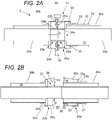
Figure 2A shows a cross-section of the pipe joint ofFigure 1 ; -
Figure 2B shows a cross-section of the pipe joint in the open configuration ofFigure 1B ; -
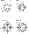
Figure 3A shows thepipe joint 1 ofFigure 1A viewed in direction X; -
Figure 3B shows the parts ofFigure 1B viewed in direction X; -
Figure 4A shows thepipe joint 1 ofFigure 1A viewed in the opposite direction Y; -
Figure 4B shows the parts ofFigure 1B viewed in the direction Y; -
Figure 5A shows another embodiment of a pipe joint in a closed configuration; -
Figure 5B shows the pipe joint ofFigure 5A in an open configuration; -
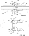
Figure 6A shows a cross-section of the pipe joint ofFigure 5A ; -
Figure 6B shows a cross-section of the pipe joint in the open configuration ofFigure 5B ; -
Figure 7 shows a spacer; and -
Figure 8 is a plan view of an aircraft. - A
pipe joint 1 is shown in a closed configuration inFigures 1A and2A , and in an open configuration inFigures 1B and2B . Thepipe joint 1 comprises an inner pipe assembly within an outer pipe assembly. Thepipe joint 1 is part of a pipe apparatus which may also include spacers remote from thepipe joint 1, as shown inFigure 7 . - The outer pipe assembly comprises a first
outer pipe portion Figure 2A ; and a secondouter pipe portion Figure 2A . Ashroud 33a couples the first outer pipe portion to the second outer pipe portion via anouter pipe joint 32. - The first outer pipe portion comprises an assembly of
parts outer pipe 30a, asleeve 31 welded to the firstouter pipe 30a, and a pipe stop in the form of acollar 50 welded to thesleeve 31. Thesleeve 31 has ashroud stop 74 in the form of an annular flange. - The second outer pipe portion comprises an assembly of
parts outer pipe 30b, and an end fitting 33b welded to the secondouter pipe 30b. As shown inFigure 2B , theend fitting 33b has afirst sleeve 34b welded to the secondouter pipe 30b; asecond sleeve 36b with a larger inner diameter than thefirst sleeve 34b, and ashoulder 35b which connects thefirst sleeve 34b to thesecond sleeve 36b. Anouter seal member 41 is mounted to the end fitting 33b. - The outer pipe joint 32 comprises an outer securing mechanism, which in this case is a V-
clamp 40 with ahinge 45. The V-clamp 40 secures theshroud 33a to the end fitting 33b of the second outer pipe portion. - While only one
pipe joint 1 is shown and described herein, it will be understood that the pipe joint may be part of a larger pipe system, comprising multiple similar pipe joints. - The inner pipe assembly comprises a first inner pipe portion coupled to a second inner pipe portion via an inner pipe joint 22.
- The first inner pipe portion comprises an assembly of parts including a first
inner pipe 20a and a first end fitting 23a. - The second inner pipe portion comprises an assembly of parts including a second
inner pipe 20b and a second end fitting 23b. - The inner pipe assembly is arranged to carry fluid, and provide an inner fluid flow path F that permits the fluid to flow across the inner pipe joint 22. The fluid may be a liquid (such as kerosene or liquid hydrogen) or a gas. Optionally the inner fluid flow path contains a liquid at a temperature below -150°C. Optionally the inner fluid flow path contains liquid hydrogen at a temperature below -250°C.
- The first end fitting 23a has a
cylindrical body 24a welded to the end of the firstinner pipe 20a, and a firstannular flange 25a that extends from thebody 24a. Similarly, the second end fitting 23b has acylindrical body 24b welded to the end of the secondinner pipe 20b and a secondannular flange 25b that extends from thebody 24b. - The first and second
annular flanges - The
second sleeve 36b has a large inner diameter to prevent it from clashing with theannular flanges - An
inner seal member 28 between theflanges - The
pipe joint 1 is assembled by first assembling the inner pipe joint 23b with theshroud 33a in its withdrawn position as shown inFigure 1B and2B , then assembling the outer pipe joint 32 as shown inFigures 1A and2A . - To assemble the inner pipe joint 22, the faces of the two
flanges fasteners 26.Figures 2A and 2B show only two of thefasteners 26 in the plane of the cross-section, but all fourfasteners 26 are shown in the end views ofFigures 3A-4B . Agap 80 provides access to the twoflanges fasteners 26 can be installed through thegap 80 and/or tightened by a tool extending through thegap 80. - The arrangement of the
inner seal member 28 and thefasteners 26 enables axial compression of theinner seal member 28 to provide a fluid tight arrangement in the inner pipe joint 22. - The
shroud 33a is movably mounted to the firstouter pipe portion first sleeve 34a which engages the first outer pipe portion; asecond sleeve 36a with a larger inner diameter than thefirst sleeve 34a; and ashoulder 35a which connects thefirst sleeve 34a to thesecond sleeve 36a. Thesecond sleeve 36a of theshroud 33a has a large inner diameter to allow theshroud 33a to axially displace without clashing with thecollar 50 or theannular flanges shroud 33a carries ashroud seal member 55. - To assemble the outer pipe joint 32 as shown in
Figure 2A , thegap 80 between theshroud 33a and the second outer pipe portion is closed by sliding theshroud 33a along the first outer pipe portion in the axial direction towards the second outer pipe portion until it comes into contact with the end fitting 33b of the second outer pipe portion. The outer pipe joint 32 is then secured using the V-clamp 40. - When the V-
clamp 40 is closed and tightened to secure theshroud 33a to the end fitting 33b, its angled faces apply an axial force which urges the two halves of the joint together, and places theouter seal member 41 in a state of compression in the axial direction. - As the
shroud 33a is slid along the first outer pipe portion, it also comes into contact with thecollar 50. When the V-clamp 40 is closed and tightened, the resultant axial force places theshroud seal member 55 in a state of compression in the axial direction. - In this example the outer securing mechanism is a V-
clamp 40, but other types of outer securing mechanism may be used to secure the outer pipe joint 32, such as fasteners similar to thefasteners 26. - By engaging the
shroud 33a, thecollar 50 is configured to inhibit movement of the firstouter pipe portion outer pipe portion Figure 2A ). Thecollar 50 also prevents theshroud 33a from being removed from the firstouter pipe portion shroud 33a is configured to disengage from thecollar 50 as it withdraws away from the second outer pipe portion. - The
sleeve 31 has ashroud stop 74 in the form of an annular flange, and an external thread (not shown). An internally threadednut 72 engages with the external thread of thesleeve 31. The inner diameter of thefirst sleeve 34a of theshroud 33a is greater than the outer diameter of the external thread, so theshroud 33a can be slid along thesleeve 31 without clashing with the external thread. When theshroud 33a has been slid into its closed position, and the V-clamp 40 has been tightened, thenut 72 is rotated on the thread until it abuts theshroud 33a as shown inFigure 2A . In the assembled joint 1 ofFigure 2A , theshroud 33a is positioned between the outer pipe joint 32 and thenut 72. Thenut 72 provides a locking function, preventing theshroud 33a from rotating. - The V-
clamp 40 can be released and opened to enable theshroud 33a to be moved along the firstouter pipe portion outer pipe portion gap 80, which provides access to the inner pipe joint 22 as shown inFigure 2B . - Thus a method of disassembling the pipe joint 1 essentially reverses the assembly method described above. The disassembly method comprises: releasing the V-
clamp 40; then moving theshroud 33a along the first outer pipe portion in the axial direction to withdraw theshroud 33a away from the second outer pipe portion, thereby opening up thegap 80 between theshroud 33a and the second outer pipe portion; and then accessing the inner pipe joint 22 via thegap 80 to disassemble the inner pipe joint 22, thereby decoupling the first inner pipe portion from the second inner pipe portion. - When the V-
clamp 40 is released and thenut 72 is rotated out of engagement with theshroud 33a, theouter seal member 41 and theshroud seal member 55 both decompress in the axial direction. The decompression force pushes theshroud 33a away from the secondouter pipe portion shroud 33a can then be slid back further to the withdrawn position ofFigure 2B to fully open up thegap 80. - The
fasteners 26 that secure the inner pipe joint 22 can then be removed via thegap 80, to enable the first and second inner pipe portions to be separated. Thegap 80 also facilitates easy access to the inner pipe joint 22 for repair purposes. Once the necessary repair has been completed, the outer pipe joint 32 can then be re-assembled. - A pipe joint 100 according to a further embodiment of the invention is shown in a closed configuration in
Figures 5A and6A and in an open configuration inFigures 5B and6B . The pipe joint 100 comprises an inner pipe assembly within an outer pipe assembly. Certain elements of the pipe joint 100 and pipe joint 1 are identical, and have therefore been given the same reference numeral and not described in further detail again below. Equivalent elements are given the same reference number, incremented by 100. - A
shroud 133a couples the first outer pipe portion to the second pipe portion via an outer pipe joint 132. - The second outer pipe portion comprises an assembly of
parts outer pipe 30b, and an end fitting 133b welded onto the secondouter pipe 30b. As shown inFigure 6B , the end fitting 133b has afirst sleeve 134b welded to the second outer pipe 130b; asecond sleeve 136b with a larger inner diameter than thefirst sleeve 134b, and ashoulder 135b which connects thefirst sleeve 134b to thesecond sleeve 136b. - The V-
clamp 40 secures theshroud 133a to the end fitting 133b of the second outer pipe portion. - The inner pipe assembly comprises a first inner pipe portion coupled to a second inner pipe portion via an inner pipe joint 122.
- The first inner pipe portion comprises an assembly of parts, including a first
inner pipe 20a and a first end fitting 123a. - The second inner pipe portion comprises an assembly of parts including a second
inner pipe 20b and a second end fitting 123b. - Similar to the
pipe assembly 1, the inner pipe assembly is arranged to carry fluid, and provide an inner fluid flow path F that permits fluid to flow across the inner pipe joint 122. - The first end fitting 123a has a
cylindrical body 124a welded to the end of the firstinner pipe 20a. Similarly, the second end fitting 123b has acylindrical body 124b welded to the end of the secondinner pipe 20b. - The
inner seal member 28 between the first end fitting 123a and second end fitting 123b creates a fluid tight arrangement preventing leaks through the inner pipe joint 122 from the inner fluid flow path F. - The pipe joint 100 is assembled by first assembling the inner pipe joint 122 with the
shroud 133a in its withdrawn position as shown inFigure 5B and6B , then assembling the outer pipe joint 132 as shown inFigures 5A and6A . - The first inner pipe portion comprises a first annular flange and the second inner pipe portion comprises a second annular flange. The first and second annular flanges contact each other at the inner pipe joint 122.
- To assemble the inner pipe joint 122, the annular flanges of the first and
second end fittings clamp 140 with ahinge 145.Gap 80 provides access to the twoend fittings V clamp 140 can be installed through thegap 80 and/or tightened by a tool extending through thegap 80. - The arrangement of the
inner seal member 28 and the V-clamp 140 enables axial compression of theinner seal member 28 to provide a fluid tight arrangement at the inner pipe joint 122. - The V-
clamp 145 can be removed via thegap 80, to enable the first and second inner pipe portions to be separated. Thegap 80 also facilitates easy access to the inner pipe joint 122 for repair purposes. Once the necessary repair has been completed, the outer pipe joint 132 can then be re-assembled. - The
shroud 133a is movably mounted to the firstouter pipe portion first sleeve 134a which engages the first outer pipe portion; asecond sleeve 136a with a larger inner diameter than thefirst sleeve 134a; and ashoulder 135a which connects thefirst sleeve 134a to thesecond sleeve 136a. Thesecond sleeve 136a of theshroud 133a has a large inner diameter. Thefirst sleeve 134a carries twoshroud seal members - The
shroud seal members shroud 133a and the firstouter pipe portion shroud seal members - To assemble the outer pipe joint 132 as shown in
Figure 6A , thegap 80 between theshroud 133a and the second outer pipe portion is closed by sliding theshroud 133a along the first outer pipe portion in the axial direction towards the second outer pipe portion until it comes into contact with the end fitting 133b of the second outer pipe portion. The outer pipe joint 132 is then secured using the V-clamp 40. - When the V-
clamp 40 is closed and tightened to secure theshroud 133a to the end fitting 133b, its angled faces apply an axial force which urges the parts together, and places theouter seal member 41 in a state of compression in the axial direction. - The V-
clamp 40 can be released and opened to enable theshroud 133a to be moved along the firstouter pipe portion outer pipe portion 130b, 133b. This opens up thegap 80, which provides access to the inner pipe joint 122 as shown inFigure 6B . - The large inner diameters of the
second sleeves clamp 140 of the inner pipe joint 122. - The following comments apply to both the
pipe joint 1 ofFigure 1 and thepipe joint 100 ofFigure 5A . - In the pipe joints 1, 100 the shroud is slidably mounted to the first outer pipe portion, and is slid along the first outer pipe portion during assembly or disassembly. In an alternative embodiment, the shroud may mounted to the first outer pipe portion on a helical thread, and moved along the first outer pipe portion during assembly or disassembly by rotating the shroud on the helical thread.
- In the pipe joints 1, 100 the inner pipe joint 23b, 123b comprises an inner securing mechanism (
fasteners 26 or V-clamp 140) which secures the first inner pipe portion to the second outer pipe portion, and theinner securing mechanism - The inner and outer pipe assemblies do not touch at the
pipe joint 1, 100 - that is, there is an absence of mechanical connection between the inner pipe assembly and the outer pipe assembly at thepipe joint - An
interspace 65 is provided between the inner pipe assembly and the outer pipe assembly. Theinterspace 65 is configured to provide an outer fluid flow path which extends in the axial direction and across the outer pipe joint 32,132. - The
interspace 65 may be used to contain any fluid which has leaked from the inner fluid flow path F. In the instance where the fluid is a cryogenic liquid such as hydrogen, theinterspace 65 may be evacuated so that it contains a vacuum. Such a vacuum provides improved thermal insulation of the inner pipe assembly. - A
continuous interspace 65 means that only a single evacuation system need be provided on one or other side of the joint 1, 100 rather than two evacuation systems (one on each side of the joint 1, 100). - The absence of mechanical connection between the inner pipe assembly and the outer pipe assembly at the
pipe joint pipe joint - To maintain the coaxial arrangement between the inner pipe assembly and the outer pipe assembly, the pipe apparatus may comprise non-metallic spacers fitted in the
interspace 65 remote from thepipe joint spacer 90 is shown inFigure 7 . - The
spacer 90 is square, with four points of contact with theouter pipe interspace 65 and has minimal conductive thermal connection with theouter pipe spacer 90 is fixed to theinner pipe outer pipe - A number of
such spacers 90 may be provided on either side of thepipe joint pipe joint such spacers 90 on either side of thepipe joint 1. Preferably there are at least three separate points of contact between thespacer 90 and theouter pipes - The
spacer 90 is shown inFigure 7 to be generally square. However, thespacer 80 may be any suitable polygonal shape as long as there are at least three separate points of contact between the spacer and theouter pipe interspace 65 may contain Multi-Layer Insulation (MLI) to reduce radiated heat transfer. - The
seal members seal members seal members - The
seal members sleeve 31 as theshroud 133a is moved. - The
seal members - The inner and outer pipe assemblies may be made of any suitable metal, such as stainless steel, titanium, aluminium. Alternatively certain parts of the pipe assemblies, such as the
outer pipes inner pipes - In the case of a cryogenic pipe system, 300-series steel is preferred as a material. In the case of a kerosene pipe system, titanium or aluminium may be preferred
- The
pipe joint pipe joint pipe joint aircraft 150 shown in Figure 9, which comprises afuselage 155 and a pair ofwings aircraft 150, which may be located in thewings fuselage 155 of the aircraft. For example the pipe joints 1, 100 may convey liquid hydrogen fuel from a hydrogen tank to a fuel cell which drives a propulsion engine on one of thewings fuselage 155. - Where the word 'or' appears this is to be construed to mean 'and/or' such that items referred to are not necessarily mutually exclusive and may be used in any appropriate combination.
- Although the invention has been described above with reference to one or more preferred embodiments, it will be appreciated that various changes or modifications may be made without departing from the scope of the invention as defined in the appended claims.
Claims (15)
- A pipe joint comprising:an outer pipe assembly comprising a first outer pipe portion, a second outer pipe portion, and a shroud which couples the first outer pipe portion to the second outer pipe portion via an outer pipe joint, wherein the outer pipe joint comprises an outer securing mechanism which secures the shroud to the second outer pipe portion; andan inner pipe assembly within the outer pipe assembly, the inner pipe assembly comprising a first inner pipe portion coupled to a second inner pipe portion via an inner pipe joint, wherein the inner pipe assembly is configured to provide an inner fluid flow path which extends in an axial direction and across the inner pipe joint,wherein the shroud is movably mounted to the first outer pipe portion, and the outer securing mechanism is configured to be releasable to enable the shroud to be moved along the first outer pipe portion in the axial direction and withdrawn away from the second outer pipe portion, thereby opening a gap between the shroud and the second outer pipe portion which provides access to the inner pipe joint.
- The pipe joint of claim 1, further comprising an interspace between the inner pipe assembly and the outer pipe assembly, wherein the interspace is configured to provide an outer fluid flow path which extends in the axial direction and across the outer pipe joint.
- The pipe joint of claim 2, wherein the interspace contains a vacuum, or the interspace is configured to contain a vacuum.
- The pipe joint of any preceding claim, wherein the outer pipe joint comprises an outer seal member between the shroud and the second outer pipe portion, wherein the outer seal member is in a state of compression in the axial direction.
- The pipe joint of any preceding claim, wherein the first outer pipe portion has an external thread, and the outer pipe assembly further comprises an internally threaded nut which is carried on the external thread of the first outer pipe portion and abuts the shroud, wherein the shroud is positioned between the outer pipe joint and the internally threaded nut.
- The pipe joint of any preceding claim, wherein the first outer pipe portion comprises a pipe stop which engages the shroud and is configured to inhibit movement of the first outer pipe portion in the axial direction away from the second outer pipe portion, wherein the shroud is configured to disengage from the pipe stop as it withdraws away from the second outer pipe portion.
- The pipe joint of any preceding claim, further comprising a shroud seal member between the shroud and the first outer pipe portion.
- The pipe joint of any preceding claim, wherein the inner pipe joint comprises an inner securing mechanism which secures the first inner pipe portion to the second outer pipe portion, the inner securing mechanism is configured to be releasable to enable the first inner pipe portion and the second inner pipe portion to be separated from each other, and the shroud is configured to enable the gap to provide access to the inner securing mechanism such that the inner securing mechanism can be released via the gap.
- The pipe joint of any preceding claim, wherein the shroud comprises a first sleeve which engages the first outer pipe portion; a second sleeve with a larger inner diameter than the first sleeve; and a shoulder which connects the first sleeve to the second sleeve.
- The pipe joint of any preceding claim, wherein the inner fluid flow path contains fluid at a temperature below -150°C, or is configured to contain fluid at a temperature below -150°C.
- The pipe joint of any preceding, wherein the inner fluid flow path contains liquid hydrogen or gaseous hydrogen, or is configured to contain liquid hydrogen or gaseous hydrogen.
- Pipe apparatus comprising the pipe joint of any preceding claim, and at least one spacer fitted between the inner pipe assembly and the outer pipe assembly, wherein the spacer is configured to maintain a co-axial relationship between the inner pipe assembly and the outer pipe assembly.
- An aircraft comprising a pipe joint according to any of claims 1 to 11 or pipe apparatus according to claim 12.
- A method of disassembling the pipe joint of any of claims 1 to 11, the method comprising:releasing the outer securing mechanism; thenmoving the shroud along the first outer pipe portion in the axial direction to withdraw the shroud away from the second outer pipe portion, thereby opening up a gap between the shroud and the second outer pipe portion; and then accessing the inner pipe joint via the gap to disassemble the inner pipe joint, thereby decoupling the first inner pipe portion from the second inner pipe portion.
- A method of assembling the pipe joint of any of claims 1 to 11, the method comprising:coupling the first inner pipe portion to the second inner pipe portion; then closing a gap between the shroud and the second outer pipe portion by moving the shroud along the first outer pipe portion in the axial direction towards the second outer pipe portion; and thencoupling the first outer pipe portion to the second outer pipe portion by securing the shroud to the second outer pipe portion with the outer securing mechanism.
Applications Claiming Priority (1)
| Application Number | Priority Date | Filing Date | Title |
|---|---|---|---|
| GB2108775.4A GB2607958A (en) | 2021-06-18 | 2021-06-18 | Pipe joint |
Publications (2)
| Publication Number | Publication Date |
|---|---|
| EP4105535A1 true EP4105535A1 (en) | 2022-12-21 |
| EP4105535B1 EP4105535B1 (en) | 2024-02-14 |
Family
ID=77050410
Family Applications (1)
| Application Number | Title | Priority Date | Filing Date |
|---|---|---|---|
| EP22173292.8A Active EP4105535B1 (en) | 2021-06-18 | 2022-05-13 | Pipe joint |
Country Status (4)
| Country | Link |
|---|---|
| US (1) | US12163612B2 (en) |
| EP (1) | EP4105535B1 (en) |
| CN (1) | CN115681637A (en) |
| GB (1) | GB2607958A (en) |
Cited By (1)
| Publication number | Priority date | Publication date | Assignee | Title |
|---|---|---|---|---|
| WO2026008993A1 (en) * | 2024-07-04 | 2026-01-08 | Gkn Aerospace Services Limited | Conduit for transporting at least of cryogenic material and electrical current |
Families Citing this family (3)
| Publication number | Priority date | Publication date | Assignee | Title |
|---|---|---|---|---|
| GB2610216A (en) * | 2021-08-27 | 2023-03-01 | Airbus Operations Gmbh | A fluid pipe connection |
| EP4325107B1 (en) * | 2022-08-19 | 2025-03-05 | Airbus Operations GmbH | Fluid transport device and method for assembling and disassembling a fluid transport device |
| US12590666B2 (en) * | 2022-09-28 | 2026-03-31 | Airbus Operations Limited | Coupling for insulated piping |
Citations (5)
| Publication number | Priority date | Publication date | Assignee | Title |
|---|---|---|---|---|
| FR527140A (en) * | 1920-05-31 | 1921-10-20 | Cfcmug | Fitting for double concentric pipes |
| US5681063A (en) * | 1995-11-28 | 1997-10-28 | E.R. Squibb & Sons, Inc. | Connector assembly for double tubing |
| US6682102B1 (en) * | 2002-09-23 | 2004-01-27 | James C. Betz | Hose-in-hose coupler |
| US6848720B2 (en) | 2002-08-09 | 2005-02-01 | The Boeing Company | Shrouded fluid-conducting apparatus |
| US7427084B1 (en) * | 2006-06-09 | 2008-09-23 | Betz James C | Hose-in-hose coupler with longitudinally shiftable sleeve |
Family Cites Families (6)
| Publication number | Priority date | Publication date | Assignee | Title |
|---|---|---|---|---|
| US5433484A (en) * | 1993-11-15 | 1995-07-18 | Enfield Industrial Corporation | Double containment pipe and fitting joint |
| US20090091126A1 (en) * | 2007-10-04 | 2009-04-09 | Carns James A | Shrouded coupling assemblies for conduits |
| EP2388503B1 (en) | 2010-05-17 | 2017-03-08 | ABB Schweiz AG | Double-walled pipe assembly |
| WO2013052741A2 (en) * | 2011-10-07 | 2013-04-11 | Eaton Corporation | Double wall tube adapter and joint |
| US9234614B2 (en) | 2014-05-05 | 2016-01-12 | Electro-Motive Diesel, Inc. | Assembly for coupling a pair of double-walled tubes |
| EP3862611A1 (en) * | 2020-02-07 | 2021-08-11 | Winterthur Gas & Diesel AG | Flange connection for connecting two double-walled pipe parts, gas supply system and large motor |
-
2021
- 2021-06-18 GB GB2108775.4A patent/GB2607958A/en active Pending
-
2022
- 2022-05-13 EP EP22173292.8A patent/EP4105535B1/en active Active
- 2022-06-16 CN CN202210678565.XA patent/CN115681637A/en active Pending
- 2022-06-17 US US17/843,257 patent/US12163612B2/en active Active
Patent Citations (5)
| Publication number | Priority date | Publication date | Assignee | Title |
|---|---|---|---|---|
| FR527140A (en) * | 1920-05-31 | 1921-10-20 | Cfcmug | Fitting for double concentric pipes |
| US5681063A (en) * | 1995-11-28 | 1997-10-28 | E.R. Squibb & Sons, Inc. | Connector assembly for double tubing |
| US6848720B2 (en) | 2002-08-09 | 2005-02-01 | The Boeing Company | Shrouded fluid-conducting apparatus |
| US6682102B1 (en) * | 2002-09-23 | 2004-01-27 | James C. Betz | Hose-in-hose coupler |
| US7427084B1 (en) * | 2006-06-09 | 2008-09-23 | Betz James C | Hose-in-hose coupler with longitudinally shiftable sleeve |
Cited By (1)
| Publication number | Priority date | Publication date | Assignee | Title |
|---|---|---|---|---|
| WO2026008993A1 (en) * | 2024-07-04 | 2026-01-08 | Gkn Aerospace Services Limited | Conduit for transporting at least of cryogenic material and electrical current |
Also Published As
| Publication number | Publication date |
|---|---|
| CN115681637A (en) | 2023-02-03 |
| GB2607958A (en) | 2022-12-21 |
| GB202108775D0 (en) | 2021-08-04 |
| US20220403968A1 (en) | 2022-12-22 |
| EP4105535B1 (en) | 2024-02-14 |
| US12163612B2 (en) | 2024-12-10 |
Similar Documents
| Publication | Publication Date | Title |
|---|---|---|
| EP4105535B1 (en) | Pipe joint | |
| US6695358B2 (en) | Controlled leak cryogenic bayonet pipe spool and system | |
| US4655483A (en) | Boundary seal for vessel penetration | |
| US4331338A (en) | Duct seal assembly | |
| JP5022492B2 (en) | Double pipe connection structure and double pipe assembly or disassembly method | |
| WO2001027514A1 (en) | Vacuum-jacketed bayonet pipe spool and pipe spool system for cryogenic fluid | |
| EP4249380B1 (en) | Fuel line safety protection system | |
| CA2212620A1 (en) | Angle entry rotary valve | |
| JP2008542639A (en) | Connector for connecting the first pipeline and the second pipeline with a joint | |
| US20250368348A1 (en) | An aircraft assembly | |
| US12292138B2 (en) | High temperature remotely connected/disconnected pipe connector for molten salt reactors | |
| EP4141310B1 (en) | FLUID PIPE CONNECTION | |
| WO2022008696A1 (en) | Gasket assembly | |
| CN211738211U (en) | A vacuum isolation valve assembly with double-layer containment structure | |
| US10876670B2 (en) | Blind flange and method of installing same for isolating hazardous energy within a facility | |
| US12098794B2 (en) | Cryogenic rotating seal | |
| US20240360960A1 (en) | Tank comprising inner and outer enclosures and at least one tubular interface in two parts passing through the inner and outer enclosures | |
| WO2002061327A2 (en) | Controlled leak cryogenic bayonet pipe spool and system | |
| JPH028673B2 (en) | ||
| RU2269455C1 (en) | Detachable joint for coupling cryogenic systems | |
| CN210859823U (en) | Oxygen stop valve | |
| Stuck | Liquid rocket disconnects, couplings, fittings, fixed joints, and seals | |
| CN101956880A (en) | Segmented fixture | |
| Kalra et al. | Study the Integrity of Flange to Gasket Connection Using ASME PCC-1 Under Bolt Tightening and Operating Condition | |
| AU2026201600A1 (en) | Emergency release mechanism of fluid loading equipment |
Legal Events
| Date | Code | Title | Description |
|---|---|---|---|
| PUAI | Public reference made under article 153(3) epc to a published international application that has entered the european phase |
Free format text: ORIGINAL CODE: 0009012 |
|
| STAA | Information on the status of an ep patent application or granted ep patent |
Free format text: STATUS: THE APPLICATION HAS BEEN PUBLISHED |
|
| AK | Designated contracting states |
Kind code of ref document: A1 Designated state(s): AL AT BE BG CH CY CZ DE DK EE ES FI FR GB GR HR HU IE IS IT LI LT LU LV MC MK MT NL NO PL PT RO RS SE SI SK SM TR |
|
| STAA | Information on the status of an ep patent application or granted ep patent |
Free format text: STATUS: REQUEST FOR EXAMINATION WAS MADE |
|
| 17P | Request for examination filed |
Effective date: 20230619 |
|
| RBV | Designated contracting states (corrected) |
Designated state(s): AL AT BE BG CH CY CZ DE DK EE ES FI FR GB GR HR HU IE IS IT LI LT LU LV MC MK MT NL NO PL PT RO RS SE SI SK SM TR |
|
| GRAP | Despatch of communication of intention to grant a patent |
Free format text: ORIGINAL CODE: EPIDOSNIGR1 |
|
| STAA | Information on the status of an ep patent application or granted ep patent |
Free format text: STATUS: GRANT OF PATENT IS INTENDED |
|
| RIC1 | Information provided on ipc code assigned before grant |
Ipc: F16L 39/00 20060101AFI20231005BHEP |
|
| INTG | Intention to grant announced |
Effective date: 20231020 |
|
| GRAS | Grant fee paid |
Free format text: ORIGINAL CODE: EPIDOSNIGR3 |
|
| GRAA | (expected) grant |
Free format text: ORIGINAL CODE: 0009210 |
|
| STAA | Information on the status of an ep patent application or granted ep patent |
Free format text: STATUS: THE PATENT HAS BEEN GRANTED |
|
| AK | Designated contracting states |
Kind code of ref document: B1 Designated state(s): AL AT BE BG CH CY CZ DE DK EE ES FI FR GB GR HR HU IE IS IT LI LT LU LV MC MK MT NL NO PL PT RO RS SE SI SK SM TR |
|
| REG | Reference to a national code |
Ref country code: GB Ref legal event code: FG4D |
|
| REG | Reference to a national code |
Ref country code: CH Ref legal event code: EP |
|
| REG | Reference to a national code |
Ref country code: DE Ref legal event code: R096 Ref document number: 602022001914 Country of ref document: DE |
|
| REG | Reference to a national code |
Ref country code: IE Ref legal event code: FG4D |
|
| REG | Reference to a national code |
Ref country code: LT Ref legal event code: MG9D |
|
| REG | Reference to a national code |
Ref country code: NL Ref legal event code: MP Effective date: 20240214 |
|
| PG25 | Lapsed in a contracting state [announced via postgrant information from national office to epo] |
Ref country code: IS Free format text: LAPSE BECAUSE OF FAILURE TO SUBMIT A TRANSLATION OF THE DESCRIPTION OR TO PAY THE FEE WITHIN THE PRESCRIBED TIME-LIMIT Effective date: 20240614 |
|
| PG25 | Lapsed in a contracting state [announced via postgrant information from national office to epo] |
Ref country code: LT Free format text: LAPSE BECAUSE OF FAILURE TO SUBMIT A TRANSLATION OF THE DESCRIPTION OR TO PAY THE FEE WITHIN THE PRESCRIBED TIME-LIMIT Effective date: 20240214 |
|
| PG25 | Lapsed in a contracting state [announced via postgrant information from national office to epo] |
Ref country code: GR Free format text: LAPSE BECAUSE OF FAILURE TO SUBMIT A TRANSLATION OF THE DESCRIPTION OR TO PAY THE FEE WITHIN THE PRESCRIBED TIME-LIMIT Effective date: 20240515 |
|
| REG | Reference to a national code |
Ref country code: AT Ref legal event code: MK05 Ref document number: 1657293 Country of ref document: AT Kind code of ref document: T Effective date: 20240214 |
|
| PG25 | Lapsed in a contracting state [announced via postgrant information from national office to epo] |
Ref country code: RS Free format text: LAPSE BECAUSE OF FAILURE TO SUBMIT A TRANSLATION OF THE DESCRIPTION OR TO PAY THE FEE WITHIN THE PRESCRIBED TIME-LIMIT Effective date: 20240514 Ref country code: HR Free format text: LAPSE BECAUSE OF FAILURE TO SUBMIT A TRANSLATION OF THE DESCRIPTION OR TO PAY THE FEE WITHIN THE PRESCRIBED TIME-LIMIT Effective date: 20240214 Ref country code: NL Free format text: LAPSE BECAUSE OF FAILURE TO SUBMIT A TRANSLATION OF THE DESCRIPTION OR TO PAY THE FEE WITHIN THE PRESCRIBED TIME-LIMIT Effective date: 20240214 |
|
| PG25 | Lapsed in a contracting state [announced via postgrant information from national office to epo] |
Ref country code: ES Free format text: LAPSE BECAUSE OF FAILURE TO SUBMIT A TRANSLATION OF THE DESCRIPTION OR TO PAY THE FEE WITHIN THE PRESCRIBED TIME-LIMIT Effective date: 20240214 |
|
| PG25 | Lapsed in a contracting state [announced via postgrant information from national office to epo] |
Ref country code: AT Free format text: LAPSE BECAUSE OF FAILURE TO SUBMIT A TRANSLATION OF THE DESCRIPTION OR TO PAY THE FEE WITHIN THE PRESCRIBED TIME-LIMIT Effective date: 20240214 |
|
| PG25 | Lapsed in a contracting state [announced via postgrant information from national office to epo] |
Ref country code: RS Free format text: LAPSE BECAUSE OF FAILURE TO SUBMIT A TRANSLATION OF THE DESCRIPTION OR TO PAY THE FEE WITHIN THE PRESCRIBED TIME-LIMIT Effective date: 20240514 Ref country code: NO Free format text: LAPSE BECAUSE OF FAILURE TO SUBMIT A TRANSLATION OF THE DESCRIPTION OR TO PAY THE FEE WITHIN THE PRESCRIBED TIME-LIMIT Effective date: 20240514 Ref country code: NL Free format text: LAPSE BECAUSE OF FAILURE TO SUBMIT A TRANSLATION OF THE DESCRIPTION OR TO PAY THE FEE WITHIN THE PRESCRIBED TIME-LIMIT Effective date: 20240214 Ref country code: LT Free format text: LAPSE BECAUSE OF FAILURE TO SUBMIT A TRANSLATION OF THE DESCRIPTION OR TO PAY THE FEE WITHIN THE PRESCRIBED TIME-LIMIT Effective date: 20240214 Ref country code: IS Free format text: LAPSE BECAUSE OF FAILURE TO SUBMIT A TRANSLATION OF THE DESCRIPTION OR TO PAY THE FEE WITHIN THE PRESCRIBED TIME-LIMIT Effective date: 20240614 Ref country code: HR Free format text: LAPSE BECAUSE OF FAILURE TO SUBMIT A TRANSLATION OF THE DESCRIPTION OR TO PAY THE FEE WITHIN THE PRESCRIBED TIME-LIMIT Effective date: 20240214 Ref country code: GR Free format text: LAPSE BECAUSE OF FAILURE TO SUBMIT A TRANSLATION OF THE DESCRIPTION OR TO PAY THE FEE WITHIN THE PRESCRIBED TIME-LIMIT Effective date: 20240515 Ref country code: FI Free format text: LAPSE BECAUSE OF FAILURE TO SUBMIT A TRANSLATION OF THE DESCRIPTION OR TO PAY THE FEE WITHIN THE PRESCRIBED TIME-LIMIT Effective date: 20240214 Ref country code: ES Free format text: LAPSE BECAUSE OF FAILURE TO SUBMIT A TRANSLATION OF THE DESCRIPTION OR TO PAY THE FEE WITHIN THE PRESCRIBED TIME-LIMIT Effective date: 20240214 Ref country code: BG Free format text: LAPSE BECAUSE OF FAILURE TO SUBMIT A TRANSLATION OF THE DESCRIPTION OR TO PAY THE FEE WITHIN THE PRESCRIBED TIME-LIMIT Effective date: 20240214 Ref country code: AT Free format text: LAPSE BECAUSE OF FAILURE TO SUBMIT A TRANSLATION OF THE DESCRIPTION OR TO PAY THE FEE WITHIN THE PRESCRIBED TIME-LIMIT Effective date: 20240214 |
|
| PG25 | Lapsed in a contracting state [announced via postgrant information from national office to epo] |
Ref country code: PT Free format text: LAPSE BECAUSE OF FAILURE TO SUBMIT A TRANSLATION OF THE DESCRIPTION OR TO PAY THE FEE WITHIN THE PRESCRIBED TIME-LIMIT Effective date: 20240614 Ref country code: PL Free format text: LAPSE BECAUSE OF FAILURE TO SUBMIT A TRANSLATION OF THE DESCRIPTION OR TO PAY THE FEE WITHIN THE PRESCRIBED TIME-LIMIT Effective date: 20240214 |
|
| PG25 | Lapsed in a contracting state [announced via postgrant information from national office to epo] |
Ref country code: SE Free format text: LAPSE BECAUSE OF FAILURE TO SUBMIT A TRANSLATION OF THE DESCRIPTION OR TO PAY THE FEE WITHIN THE PRESCRIBED TIME-LIMIT Effective date: 20240214 Ref country code: PT Free format text: LAPSE BECAUSE OF FAILURE TO SUBMIT A TRANSLATION OF THE DESCRIPTION OR TO PAY THE FEE WITHIN THE PRESCRIBED TIME-LIMIT Effective date: 20240614 Ref country code: PL Free format text: LAPSE BECAUSE OF FAILURE TO SUBMIT A TRANSLATION OF THE DESCRIPTION OR TO PAY THE FEE WITHIN THE PRESCRIBED TIME-LIMIT Effective date: 20240214 Ref country code: LV Free format text: LAPSE BECAUSE OF FAILURE TO SUBMIT A TRANSLATION OF THE DESCRIPTION OR TO PAY THE FEE WITHIN THE PRESCRIBED TIME-LIMIT Effective date: 20240214 |
|
| PG25 | Lapsed in a contracting state [announced via postgrant information from national office to epo] |
Ref country code: DK Free format text: LAPSE BECAUSE OF FAILURE TO SUBMIT A TRANSLATION OF THE DESCRIPTION OR TO PAY THE FEE WITHIN THE PRESCRIBED TIME-LIMIT Effective date: 20240214 |
|
| PG25 | Lapsed in a contracting state [announced via postgrant information from national office to epo] |
Ref country code: SM Free format text: LAPSE BECAUSE OF FAILURE TO SUBMIT A TRANSLATION OF THE DESCRIPTION OR TO PAY THE FEE WITHIN THE PRESCRIBED TIME-LIMIT Effective date: 20240214 |
|
| PG25 | Lapsed in a contracting state [announced via postgrant information from national office to epo] |
Ref country code: EE Free format text: LAPSE BECAUSE OF FAILURE TO SUBMIT A TRANSLATION OF THE DESCRIPTION OR TO PAY THE FEE WITHIN THE PRESCRIBED TIME-LIMIT Effective date: 20240214 Ref country code: CZ Free format text: LAPSE BECAUSE OF FAILURE TO SUBMIT A TRANSLATION OF THE DESCRIPTION OR TO PAY THE FEE WITHIN THE PRESCRIBED TIME-LIMIT Effective date: 20240214 |
|
| PG25 | Lapsed in a contracting state [announced via postgrant information from national office to epo] |
Ref country code: SK Free format text: LAPSE BECAUSE OF FAILURE TO SUBMIT A TRANSLATION OF THE DESCRIPTION OR TO PAY THE FEE WITHIN THE PRESCRIBED TIME-LIMIT Effective date: 20240214 |
|
| PG25 | Lapsed in a contracting state [announced via postgrant information from national office to epo] |
Ref country code: SM Free format text: LAPSE BECAUSE OF FAILURE TO SUBMIT A TRANSLATION OF THE DESCRIPTION OR TO PAY THE FEE WITHIN THE PRESCRIBED TIME-LIMIT Effective date: 20240214 Ref country code: SK Free format text: LAPSE BECAUSE OF FAILURE TO SUBMIT A TRANSLATION OF THE DESCRIPTION OR TO PAY THE FEE WITHIN THE PRESCRIBED TIME-LIMIT Effective date: 20240214 Ref country code: RO Free format text: LAPSE BECAUSE OF FAILURE TO SUBMIT A TRANSLATION OF THE DESCRIPTION OR TO PAY THE FEE WITHIN THE PRESCRIBED TIME-LIMIT Effective date: 20240214 Ref country code: EE Free format text: LAPSE BECAUSE OF FAILURE TO SUBMIT A TRANSLATION OF THE DESCRIPTION OR TO PAY THE FEE WITHIN THE PRESCRIBED TIME-LIMIT Effective date: 20240214 Ref country code: DK Free format text: LAPSE BECAUSE OF FAILURE TO SUBMIT A TRANSLATION OF THE DESCRIPTION OR TO PAY THE FEE WITHIN THE PRESCRIBED TIME-LIMIT Effective date: 20240214 Ref country code: CZ Free format text: LAPSE BECAUSE OF FAILURE TO SUBMIT A TRANSLATION OF THE DESCRIPTION OR TO PAY THE FEE WITHIN THE PRESCRIBED TIME-LIMIT Effective date: 20240214 |
|
| REG | Reference to a national code |
Ref country code: DE Ref legal event code: R097 Ref document number: 602022001914 Country of ref document: DE |
|
| PG25 | Lapsed in a contracting state [announced via postgrant information from national office to epo] |
Ref country code: IT Free format text: LAPSE BECAUSE OF FAILURE TO SUBMIT A TRANSLATION OF THE DESCRIPTION OR TO PAY THE FEE WITHIN THE PRESCRIBED TIME-LIMIT Effective date: 20240214 |
|
| PLBE | No opposition filed within time limit |
Free format text: ORIGINAL CODE: 0009261 |
|
| STAA | Information on the status of an ep patent application or granted ep patent |
Free format text: STATUS: NO OPPOSITION FILED WITHIN TIME LIMIT |
|
| PG25 | Lapsed in a contracting state [announced via postgrant information from national office to epo] |
Ref country code: IT Free format text: LAPSE BECAUSE OF FAILURE TO SUBMIT A TRANSLATION OF THE DESCRIPTION OR TO PAY THE FEE WITHIN THE PRESCRIBED TIME-LIMIT Effective date: 20240214 |
|
| PG25 | Lapsed in a contracting state [announced via postgrant information from national office to epo] |
Ref country code: MC Free format text: LAPSE BECAUSE OF FAILURE TO SUBMIT A TRANSLATION OF THE DESCRIPTION OR TO PAY THE FEE WITHIN THE PRESCRIBED TIME-LIMIT Effective date: 20240214 |
|
| PG25 | Lapsed in a contracting state [announced via postgrant information from national office to epo] |
Ref country code: LU Free format text: LAPSE BECAUSE OF NON-PAYMENT OF DUE FEES Effective date: 20240513 |
|
| 26N | No opposition filed |
Effective date: 20241115 |
|
| PG25 | Lapsed in a contracting state [announced via postgrant information from national office to epo] |
Ref country code: MC Free format text: LAPSE BECAUSE OF FAILURE TO SUBMIT A TRANSLATION OF THE DESCRIPTION OR TO PAY THE FEE WITHIN THE PRESCRIBED TIME-LIMIT Effective date: 20240214 Ref country code: LU Free format text: LAPSE BECAUSE OF NON-PAYMENT OF DUE FEES Effective date: 20240513 |
|
| REG | Reference to a national code |
Ref country code: BE Ref legal event code: MM Effective date: 20240531 |
|
| PG25 | Lapsed in a contracting state [announced via postgrant information from national office to epo] |
Ref country code: IE Free format text: LAPSE BECAUSE OF NON-PAYMENT OF DUE FEES Effective date: 20240513 |
|
| PG25 | Lapsed in a contracting state [announced via postgrant information from national office to epo] |
Ref country code: SI Free format text: LAPSE BECAUSE OF FAILURE TO SUBMIT A TRANSLATION OF THE DESCRIPTION OR TO PAY THE FEE WITHIN THE PRESCRIBED TIME-LIMIT Effective date: 20240214 Ref country code: BE Free format text: LAPSE BECAUSE OF NON-PAYMENT OF DUE FEES Effective date: 20240531 |
|
| PGFP | Annual fee paid to national office [announced via postgrant information from national office to epo] |
Ref country code: DE Payment date: 20250521 Year of fee payment: 4 |
|
| PGFP | Annual fee paid to national office [announced via postgrant information from national office to epo] |
Ref country code: FR Payment date: 20250528 Year of fee payment: 4 |
|
| PG25 | Lapsed in a contracting state [announced via postgrant information from national office to epo] |
Ref country code: CY Free format text: LAPSE BECAUSE OF FAILURE TO SUBMIT A TRANSLATION OF THE DESCRIPTION OR TO PAY THE FEE WITHIN THE PRESCRIBED TIME-LIMIT; INVALID AB INITIO Effective date: 20220513 |
|
| PG25 | Lapsed in a contracting state [announced via postgrant information from national office to epo] |
Ref country code: HU Free format text: LAPSE BECAUSE OF FAILURE TO SUBMIT A TRANSLATION OF THE DESCRIPTION OR TO PAY THE FEE WITHIN THE PRESCRIBED TIME-LIMIT; INVALID AB INITIO Effective date: 20220513 |
|
| REG | Reference to a national code |
Ref country code: CH Ref legal event code: H13 Free format text: ST27 STATUS EVENT CODE: U-0-0-H10-H13 (AS PROVIDED BY THE NATIONAL OFFICE) Effective date: 20251223 |
|
| PG25 | Lapsed in a contracting state [announced via postgrant information from national office to epo] |
Ref country code: CH Free format text: LAPSE BECAUSE OF NON-PAYMENT OF DUE FEES Effective date: 20250531 |