EP4105494A1 - Invisible fan and fan lamp - Google Patents
Invisible fan and fan lamp Download PDFInfo
- Publication number
- EP4105494A1 EP4105494A1 EP21833377.1A EP21833377A EP4105494A1 EP 4105494 A1 EP4105494 A1 EP 4105494A1 EP 21833377 A EP21833377 A EP 21833377A EP 4105494 A1 EP4105494 A1 EP 4105494A1
- Authority
- EP
- European Patent Office
- Prior art keywords
- fan
- turntable
- position limit
- rotation
- hiding
- Prior art date
- Legal status (The legal status is an assumption and is not a legal conclusion. Google has not performed a legal analysis and makes no representation as to the accuracy of the status listed.)
- Granted
Links
Images



Classifications
-
- F—MECHANICAL ENGINEERING; LIGHTING; HEATING; WEAPONS; BLASTING
- F04—POSITIVE - DISPLACEMENT MACHINES FOR LIQUIDS; PUMPS FOR LIQUIDS OR ELASTIC FLUIDS
- F04D—NON-POSITIVE-DISPLACEMENT PUMPS
- F04D29/00—Details, component parts, or accessories
- F04D29/26—Rotors specially for elastic fluids
- F04D29/32—Rotors specially for elastic fluids for axial flow pumps
- F04D29/34—Blade mountings
- F04D29/36—Blade mountings adjustable
-
- F—MECHANICAL ENGINEERING; LIGHTING; HEATING; WEAPONS; BLASTING
- F04—POSITIVE - DISPLACEMENT MACHINES FOR LIQUIDS; PUMPS FOR LIQUIDS OR ELASTIC FLUIDS
- F04D—NON-POSITIVE-DISPLACEMENT PUMPS
- F04D25/00—Pumping installations or systems
- F04D25/02—Units comprising pumps and their driving means
- F04D25/08—Units comprising pumps and their driving means the working fluid being air, e.g. for ventilation
- F04D25/088—Ceiling fans
-
- F—MECHANICAL ENGINEERING; LIGHTING; HEATING; WEAPONS; BLASTING
- F04—POSITIVE - DISPLACEMENT MACHINES FOR LIQUIDS; PUMPS FOR LIQUIDS OR ELASTIC FLUIDS
- F04D—NON-POSITIVE-DISPLACEMENT PUMPS
- F04D29/00—Details, component parts, or accessories
- F04D29/26—Rotors specially for elastic fluids
- F04D29/32—Rotors specially for elastic fluids for axial flow pumps
- F04D29/34—Blade mountings
- F04D29/36—Blade mountings adjustable
- F04D29/362—Blade mountings adjustable during rotation
- F04D29/366—Adjustment by interaction of inertion and lift
-
- F—MECHANICAL ENGINEERING; LIGHTING; HEATING; WEAPONS; BLASTING
- F04—POSITIVE - DISPLACEMENT MACHINES FOR LIQUIDS; PUMPS FOR LIQUIDS OR ELASTIC FLUIDS
- F04D—NON-POSITIVE-DISPLACEMENT PUMPS
- F04D29/00—Details, component parts, or accessories
- F04D29/26—Rotors specially for elastic fluids
- F04D29/32—Rotors specially for elastic fluids for axial flow pumps
- F04D29/38—Blades
-
- F—MECHANICAL ENGINEERING; LIGHTING; HEATING; WEAPONS; BLASTING
- F04—POSITIVE - DISPLACEMENT MACHINES FOR LIQUIDS; PUMPS FOR LIQUIDS OR ELASTIC FLUIDS
- F04D—NON-POSITIVE-DISPLACEMENT PUMPS
- F04D29/00—Details, component parts, or accessories
- F04D29/26—Rotors specially for elastic fluids
- F04D29/32—Rotors specially for elastic fluids for axial flow pumps
- F04D29/38—Blades
- F04D29/382—Flexible blades
-
- F—MECHANICAL ENGINEERING; LIGHTING; HEATING; WEAPONS; BLASTING
- F21—LIGHTING
- F21V—FUNCTIONAL FEATURES OR DETAILS OF LIGHTING DEVICES OR SYSTEMS THEREOF; STRUCTURAL COMBINATIONS OF LIGHTING DEVICES WITH OTHER ARTICLES, NOT OTHERWISE PROVIDED FOR
- F21V23/00—Arrangement of electric circuit elements in or on lighting devices
- F21V23/003—Arrangement of electric circuit elements in or on lighting devices the elements being electronics drivers or controllers for operating the light source, e.g. for a LED array
-
- F—MECHANICAL ENGINEERING; LIGHTING; HEATING; WEAPONS; BLASTING
- F21—LIGHTING
- F21V—FUNCTIONAL FEATURES OR DETAILS OF LIGHTING DEVICES OR SYSTEMS THEREOF; STRUCTURAL COMBINATIONS OF LIGHTING DEVICES WITH OTHER ARTICLES, NOT OTHERWISE PROVIDED FOR
- F21V33/00—Structural combinations of lighting devices with other articles, not otherwise provided for
- F21V33/0088—Ventilating systems
- F21V33/0096—Fans, e.g. ceiling fans
-
- F—MECHANICAL ENGINEERING; LIGHTING; HEATING; WEAPONS; BLASTING
- F21—LIGHTING
- F21V—FUNCTIONAL FEATURES OR DETAILS OF LIGHTING DEVICES OR SYSTEMS THEREOF; STRUCTURAL COMBINATIONS OF LIGHTING DEVICES WITH OTHER ARTICLES, NOT OTHERWISE PROVIDED FOR
- F21V23/00—Arrangement of electric circuit elements in or on lighting devices
- F21V23/003—Arrangement of electric circuit elements in or on lighting devices the elements being electronics drivers or controllers for operating the light source, e.g. for a LED array
- F21V23/007—Arrangement of electric circuit elements in or on lighting devices the elements being electronics drivers or controllers for operating the light source, e.g. for a LED array enclosed in a casing
- F21V23/008—Arrangement of electric circuit elements in or on lighting devices the elements being electronics drivers or controllers for operating the light source, e.g. for a LED array enclosed in a casing the casing being outside the housing of the lighting device
Definitions
- the present disclosure relates to the technical field of fans, in particular to a hiding fan.
- the hiding fan expands the fan blades when in use, and fold the fan blades when not in use, to avoid dust accumulation on the fan blades.
- the hiding fan has a plurality of fan blades, and the plurality of fan blades are connected to each other through a synchronization mechanism such as a gear mechanism and a link mechanism, etc., so that each fan blade rotates synchronously.
- a synchronization mechanism such as a gear mechanism and a link mechanism, etc.
- the present disclosure discloses a hiding fan, aiming at solving the problems that the existing hiding fan has high design cost and manufacturing cost, and is not conducive to subsequent maintenance.
- a hiding fan comprises a turntable, a plurality of fan blades, and a synchronization mechanism
- the synchronization mechanism comprises a rotation ring and a plurality of connection rods
- a total number of the connection rods is equal to a total number of the fan blades
- the rotation ring is mounted on the turntable
- the rotation ring is configured to rotate relative to the turntable around a central axis of the turntable
- the fan blade has an installation end and a free end
- the installation end has an installation portion and a connection portion that are spaced apart from each other
- the installation portion is mounted on the turntable through a first rotation connection portion
- a first end of the connection rod is mounted on the turntable on the rotation ring through a second rotation connection portion
- a second end of the connection rod is mounted on the connection portion through a third rotation connection portion
- the fan blade is configured to rotate around a central axis of the first rotation connection portion
- the fan blade is configured to switch between a storage
- a fan lamp comprises a lamp assembly, a motor assembly and an hiding fan according to the above descriptions, the lamp assembly is arranged on the side of the turntable facing away from the fan blades, the motor assembly is arranged on the side of the turntable facing the fan blades, and the rotating ring is sleeved on the outer periphery of the motor assembly.
- each fan blade is connected with each other through the synchronization mechanism, so that each fan blade can be synchronously unfolded, or, folded and stored;
- the synchronization mechanism comprises a rotation ring and a connection rod; for hiding fans with different sizes, only the size of the connection rod needs to be changed, so that the same rotation ring can be applied to hiding fans with different sizes, the design cost and manufacturing cost of the hiding fan are reduced, and the subsequent maintenance of the hiding fan is facilitated.
- the hiding fan includes a turntable 100, a plurality of fan blades 200 and a synchronization mechanism 300.
- the synchronization mechanism 300 includes a rotation ring 310 and a plurality of connection rods 320.
- the number of the connection rods 320 is equal to the number of the fan blades 200.
- the rotation ring 310 is mounted on the turntable 100, and the rotation ring 310 is configured to rotate relative to the turntable 100 around the central axis of the turntable 100.
- Each fan blade 200 has an installation end and a free end, the installation end has an installation portion 210 and a connection portion 220 that are spaced apart from each other, the installation portion 210 is mounted on the turntable 100 through the first rotation connection portion 400; a first end of the connection rod 320 is mounted on the turntable 100 on the rotation ring 310 through a second rotation connection portion 500, a second end of the connection rod 320 is mounted on the connection portion 220 through a third rotation connection portion 600; the fan blades 200 is configured to rotate around the central axis of the first rotation connection portion 400 , and the fan blades 200 is configured to switch between the storage position and the unfolded position by rotating.
- the plurality of fan blades 200 are connected to each other through a synchronization mechanism 300, so that each fan blade 200 is synchronously unfolded, or, synchronously folded and stored;
- the synchronization mechanism 300 includes a rotation ring 310 and a connection rod 320; for hiding fans of different sizes, it is only required to change the size of the connection rod 320, so that the same rotation ring 310 can adapt to hiding fans of different sizes, reducing the design cost and manufacturing cost of the hiding fan, and facilitating the subsequent maintenance of the hiding fan.
- the turntable 100 has a plurality of fan blade installation portions 140, and the plurality of fan blade installation portions 140 are evenly spaced apart from each other along a circumferential direction of the turntable 100;
- the first rotation connection portion 400 includes a first rotation shaft, and the installation portion 210 is mounted on the fan blade installation portion 140 through the first rotation shaft.
- the rotation ring 310 has a plurality of connection rod installation portions 311, and the plurality of the connection rod installation portions 311 are evenly spaced apart from each along a circumferential direction of the rotation ring 310;
- the second rotation connection portion 500 includes a second rotation shaft, and the first end of the connection rod 320 is mounted on the connection rod installation portions 311 through the second rotation shaft.
- the third rotation connection portion 600 includes a third rotation shaft, and the second end of the connection rod 320 is mounted on the connection portion 220 through the third rotation shaft.
- the first rotation connection portion 400, the second rotation connection portion 500 and the third rotation connection portion 600 have simple structures, which is convenient for the assembly of the hiding fan.
- the plurality of connection rod installation portions 311 are alternately arranged with the plurality of fan blades installation portions 140; the intervals between the connection rod installation portions 311 and the fan blade installation portions 140 are increased, which is convenient for the arrangement of the connection rods 320, helps the fan blades 200 to switch smoothly between the storage position and the unfolded position, and makes the structure of the hiding fan more compact.
- a distance between the second rotation connection portion 500 and the third rotation connection portion 600 is a first distance L1; in the case where the fan blades 200 are in the unfolded position, along a radial direction of the turntable 100, a distance between the second rotation connection portion 500 and the third rotation connection portion 600 is a second distance L2; and the first distance L1 is greater than the second distance L2.
- a distance between the first rotation connection portion 400 and the third rotation connection portion 600 is a third distance L3, and preferably, the third distance L3 is smaller than the first distance L1, so that the structure of the hiding fan is more compact.
- the hiding fan has a position limit structure, and the position limit structure includes a unfolded position limit portion and a storage position limit portion, so that the fan blade 200 can only rotate between the unfolded position and the storage position, so as to prevent the rotation of the fan blades 200 from exceeding an expected range and improve the stability and reliability of the hiding fan.
- the specific structure of the position limit structure may be appropriately selected according to actual needs, for example, an arc-shaped positon limit groove is provided on the rotation ring 310, and the turntable 100 has a protrusion block inserted into the arc-shaped positon limit groove; in the case where the fan blades 200 are in the unfolded position, the protruding block abuts against one end of the arc-shaped limiting slot; in the case where the fan blades 200 are in the storage position, the protruding block abuts against the other end of the arc-shaped limiting slot.
- the unfolded position limit portion includes a first position limit structure 131 and a second position limit structure 312 that cooperate with each other, and the storage position limit portion includes a third position limit structure 120 and a fourth position limit structure 230 that cooperate with each other;
- the first position limit structure 131 and the third position limit structure 120 are arranged on the turntable 100
- the second position limit structure 312 is arranged on one selected from the group consisting of the rotation ring 310 and the fan blades 200
- the fourth position limit structure 230 is arranged on the other selected from the group consisting of the rotation ring 310 and the fan blades 200.
- the storage position limit portion and the unfolded position limit portion are separated from each other, so as to avoid the simultaneous failure of the storage position limit portion and the unfolded position limit portion, and so that the space required for the arrangement of the storage position limit portion and the unfolded position limit portion which are arranged separately is smaller, which makes the structure of the hiding fan more compact.
- the turntable 100 includes an annular installation seat 130, the rotation ring 310 is sleeved on the outer side of the annular installation seat 130; the first position limit structure 131 is arranged on the annular installation seat 130, the second position limit structure 312 is arranged on the rotation ring 310; the first position limit structure 131 is a first position limit protrusion protruding toward the rotation ring 310 along a radial direction of the turntable 100, and the second position limit structure 312 is a second position limit protrusion protruding toward the annular installation seat 130 along the radial direction of the turntable 100; in the case that the fan blades 200 are in the unfolded position, the first position limit protrusion and the second position limit protrusion abut against each other, so as to prevent the fan blades 200 from continuing to rotate toward the direction which makes the fan blades 200 be unfolded.
- the fourth position limit structures 230 are respectively arranged on the fan blades 200, the third position limit structure 120 is a third position limitation protrusion protruding toward the fan blades 200 along a thickness direction of the turntable 100, and the fourth position limit structure 230 a fourth position limitation protrusion protruding toward the turntable 100 along a thickness direction of the turntable 100.
- the third position limitation protrusion and the fourth position limitation protrusion abut against each other, so as to prevent the fan blades 200 from continuing to rotate toward the direction which makes the fan blades 200 be folded and stored.
- the above-mentioned unfolded position limit portion and storage position limit portion are simple in structure, require less space for arrangement, and facilitate the arrangement of the position limit structure.
- the hiding fan further includes an elastic reset member (not shown in the figures), the elastic reset member includes a first installation portion and a second installation portion; the first installation portion is fixed relative to the turntable 100, and the second installation portion is fixed relative to the fan blades 200.
- the elastic reset member applies an elastic force to the fan blades 200 to keep the fan blades 200 in the storage position; once the fan blades 200 stop rotating, they will return to the storage position under the action of the elastic force of the elastic reset member.
- the fan blade 200 starts to rotate under the driving of the driver motor 820, and the centrifugal force of the fan blades 200 overcomes the elastic force of the elastic reset member, so that the fan blades 200 automatically stretch to the unfolded position; when the hiding fan is closed, the fan blades 200 stop rotating, the centrifugal force disappears, and the fan blades 200 are reset to the storage position under the action of the elastic force of the elastic reset member.
- the fan lamp includes a lamp assembly 900, a motor assembly 800 and the hiding fan described above; the lamp assembly 900 is arranged on the side of the turntable 100 away from the fan blades 200, the motor assembly 800 is arranged on the side of the turntable 100 facing the fan blades 200, and the rotation ring 310 is sleeved on the outer periphery of the motor assembly 800; the fan lamp has the same advantages as the above-mentioned hiding fan, and the same advantages are not repeated here.
- the fan lamp includes a driver 710; the driver 710 is electrically connected to the motor assembly 800 through a first electrical connector, and the driver 710 is electrically connected to the lamp assembly 900 through a second electrical connector.
- the motor assembly 800 and the lamp assembly 900 for driving the fan blade 200 may be electrically connected with the same driver 710, so that the hiding fan and the lamp assembly 900 cab be driven by the same one driver 710; compared with the way in which the hiding fan and the lamp assembly 900 are respectively driven by their respective drivers, the number of parts and components of the fan lamp disclosed in the embodiments of the present disclosure is reduced, so the fan lamp occupies a smaller space and, meanwhile, facilitates the transportation of the fan lamp.
- the motor assembly 800 includes a motor cover 810 and a driver motor 820 mounted in the motor cover 810; the motor cover 810 can protect the driver motor 820 and make the appearance of the fan lamp more beautiful.
- the driver motor 820 may be connected to the turntable 100 by transmission in any appropriate manner; in the embodiments of the present disclosure, the driver motor 820 is fixedly mounted on the annular installation seat 130, and the annular installation seat 130 has a central opening 110 in the middle to reduce the weight of the turntable 100and avoid interference between the turntable 100 and the driver motor 820.
- the lamp assembly 900 includes a lamp plate 910, a light source module 920 and a lamp shade 930.
- the fan lamp includes an installation assembly 700
- the installation assembly 700 includes an installation house 730 and a hanger 720 fixedly mounted in the installation house 730, and the driver 710 is fixedly connected to the hanger 720, which facilitates the installation and fixation of the driver 710, and the installation house 730 can protect the driver 710.
Landscapes
- Engineering & Computer Science (AREA)
- General Engineering & Computer Science (AREA)
- Mechanical Engineering (AREA)
- Microelectronics & Electronic Packaging (AREA)
- Structures Of Non-Positive Displacement Pumps (AREA)
Abstract
Description
- The present disclosure relates to the technical field of fans, in particular to a hiding fan.
- The hiding fan expands the fan blades when in use, and fold the fan blades when not in use, to avoid dust accumulation on the fan blades. The hiding fan has a plurality of fan blades, and the plurality of fan blades are connected to each other through a synchronization mechanism such as a gear mechanism and a link mechanism, etc., so that each fan blade rotates synchronously. However, the structure of the existing synchronization mechanism is relatively complicated, and once the size of the fan blade is adjusted, the synchronization mechanism needs to be replaced as a whole, which leads to high design cost and manufacturing cost of the hiding fan, and is not conducive to the subsequent maintenance of the hiding fan.
- Therefore, it would be desirable to have a hiding fan that overcomes or at least alleviates the above-mentioned deficiencies of the prior art.
- The present disclosure discloses a hiding fan, aiming at solving the problems that the existing hiding fan has high design cost and manufacturing cost, and is not conducive to subsequent maintenance.
- To solve the above problems, the present disclosure adopts the following technical scheme:
a hiding fan comprises a turntable, a plurality of fan blades, and a synchronization mechanism, the synchronization mechanism comprises a rotation ring and a plurality of connection rods, a total number of the connection rods is equal to a total number of the fan blades, the rotation ring is mounted on the turntable, the rotation ring is configured to rotate relative to the turntable around a central axis of the turntable, the fan blade has an installation end and a free end, the installation end has an installation portion and a connection portion that are spaced apart from each other, the installation portion is mounted on the turntable through a first rotation connection portion, a first end of the connection rod is mounted on the turntable on the rotation ring through a second rotation connection portion, a second end of the connection rod is mounted on the connection portion through a third rotation connection portion, the fan blade is configured to rotate around a central axis of the first rotation connection portion, and the fan blade is configured to switch between a storage position and a unfolded position by rotating. - A fan lamp comprises a lamp assembly, a motor assembly and an hiding fan according to the above descriptions, the lamp assembly is arranged on the side of the turntable facing away from the fan blades, the motor assembly is arranged on the side of the turntable facing the fan blades, and the rotating ring is sleeved on the outer periphery of the motor assembly.
- The technical scheme adopted by the present disclosure can achieve the following beneficial effects:
in the hiding fan disclosed by the present disclosure, each fan blade is connected with each other through the synchronization mechanism, so that each fan blade can be synchronously unfolded, or, folded and stored; the synchronization mechanism comprises a rotation ring and a connection rod; for hiding fans with different sizes, only the size of the connection rod needs to be changed, so that the same rotation ring can be applied to hiding fans with different sizes, the design cost and manufacturing cost of the hiding fan are reduced, and the subsequent maintenance of the hiding fan is facilitated. - The drawings described herein are used to provide a further understanding of the present disclosure and constitute a part of the present disclosure; the exemplary embodiments of the present disclosure and their descriptions are used to explain the present disclosure without constituting any limitation thereto. In the attached image:
-
FIG. 1 is a schematic diagram of a fan lamp disclosed by an embodiment of the present disclosure, in which the fan blades are in a storage position; -
FIG. 2 is an exploded view of the fan lamp shown inFIG. 1 , where the fan blades are in a unfolded position; -
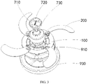
FIG. 3 is another exploded view of the fan lamp shown inFIG. 1 , where the fan blades are in the unfolded position; -
FIG. 4 a schematic diagram of a hiding fan disclosed according to an embodiment of the present disclosure, where the fan blades are in the unfolded position; -
FIG. 5 is a partial enlarged schematic diagram of an A portion of the hiding fan shown inFIG. 4 ; -
FIG. 6 is a schematic diagram of the hiding fan shown inFIG. 4 , in which the fan blades are in the storage position; -
FIG. 7 is a partial enlarged schematic diagram of a B portion of the hiding fan shown inFIG. 6 ; and -
FIG. 8 is a schematic diagram of the fan blades of the hiding fan shown inFIG. 5 . - 100-turntable, 110-central opening, 120-the third position limit structure, 130-annular installation seat, 131-the first position limit structure, 140-fan blade installation portion, 200-fan blade, 210-installation portion, 220-connection portion, 230-the fourth position limit structure, 300-synchronization mechanism, 310-rotation ring, 311-connection rod installation portion, 312-the second position limit structure, 320-connection rod, 400-first rotation connection portion, 500-second rotation connection portion, 600-the third rotation connection portion, 700-installation assembly, 710-driver, 720-hanger, 730-installation house, 800-motor assembly, 810-motor cover, 820-driver motor, 900-lamp assembly, 910-lamp plate, 920-light source module, 930-lamp shade, L1-the first distance, L2-the second distance, L3-the third distance.
- In order to make objectives, technical solutions and advantages of the present disclosure more clearly, the technical solutions of the present disclosure will be described in a clearly and fully understandable way in connection with the specific embodiments of the present disclosure and the corresponding drawings. Apparently, the described embodiments are just a part but not all of the embodiments of the present disclosure. Based on the described embodiments herein, those skilled in the art can obtain other embodiment(s), without any inventive work, which should be within the scope of the present disclosure.
- The technical solutions disclosed in the various embodiments of the present disclosure are described in detail below in conjunction with the drawings.
- An embodiment of the present disclosure discloses a hiding fan. Referring to
FIG. 1 to FIG. 8 , the hiding fan includes aturntable 100, a plurality offan blades 200 and asynchronization mechanism 300. - The
synchronization mechanism 300 includes arotation ring 310 and a plurality ofconnection rods 320. The number of theconnection rods 320 is equal to the number of thefan blades 200. Therotation ring 310 is mounted on theturntable 100, and therotation ring 310 is configured to rotate relative to theturntable 100 around the central axis of theturntable 100. - Each
fan blade 200 has an installation end and a free end, the installation end has aninstallation portion 210 and aconnection portion 220 that are spaced apart from each other, theinstallation portion 210 is mounted on theturntable 100 through the firstrotation connection portion 400; a first end of theconnection rod 320 is mounted on theturntable 100 on therotation ring 310 through a secondrotation connection portion 500, a second end of theconnection rod 320 is mounted on theconnection portion 220 through a thirdrotation connection portion 600; thefan blades 200 is configured to rotate around the central axis of the firstrotation connection portion 400 , and thefan blades 200 is configured to switch between the storage position and the unfolded position by rotating. - In the hiding fan disclosed in the present disclosure, the plurality of
fan blades 200 are connected to each other through asynchronization mechanism 300, so that eachfan blade 200 is synchronously unfolded, or, synchronously folded and stored; thesynchronization mechanism 300 includes arotation ring 310 and aconnection rod 320; for hiding fans of different sizes, it is only required to change the size of theconnection rod 320, so that thesame rotation ring 310 can adapt to hiding fans of different sizes, reducing the design cost and manufacturing cost of the hiding fan, and facilitating the subsequent maintenance of the hiding fan. - The structures of the first
rotation connection portion 400, the secondrotation connection portion 500 and the thirdrotation connection portion 600 may be appropriately selected according to actual needs. Referring toFIG. 5 , in at least one embodiment of the present disclosure, theturntable 100 has a plurality of fanblade installation portions 140, and the plurality of fanblade installation portions 140 are evenly spaced apart from each other along a circumferential direction of theturntable 100; the firstrotation connection portion 400 includes a first rotation shaft, and theinstallation portion 210 is mounted on the fanblade installation portion 140 through the first rotation shaft. Therotation ring 310 has a plurality of connectionrod installation portions 311, and the plurality of the connectionrod installation portions 311 are evenly spaced apart from each along a circumferential direction of therotation ring 310; the secondrotation connection portion 500 includes a second rotation shaft, and the first end of theconnection rod 320 is mounted on the connectionrod installation portions 311 through the second rotation shaft. The thirdrotation connection portion 600 includes a third rotation shaft, and the second end of theconnection rod 320 is mounted on theconnection portion 220 through the third rotation shaft. The firstrotation connection portion 400, the secondrotation connection portion 500 and the thirdrotation connection portion 600 have simple structures, which is convenient for the assembly of the hiding fan. - Optionally, referring to
FIG. 2 ,FIG. 4 andFIG. 5 , along the circumferential direction of theturntable 100, the plurality of connectionrod installation portions 311 are alternately arranged with the plurality of fanblades installation portions 140; the intervals between the connectionrod installation portions 311 and the fanblade installation portions 140 are increased, which is convenient for the arrangement of theconnection rods 320, helps thefan blades 200 to switch smoothly between the storage position and the unfolded position, and makes the structure of the hiding fan more compact. - Referring to
FIG. 4 again, in the embodiment of the present disclosure, along a length direction of theconnection rod 320, a distance between the secondrotation connection portion 500 and the thirdrotation connection portion 600 is a first distance L1; in the case where thefan blades 200 are in the unfolded position, along a radial direction of theturntable 100, a distance between the secondrotation connection portion 500 and the thirdrotation connection portion 600 is a second distance L2; and the first distance L1 is greater than the second distance L2. Because the first distance L1 is greater than the second distance L2, the extending direction of theconnection rod 320 does not coincide with the radial direction of theturntable 100 during the entire movement process of theconnection rod 320, so that a link mechanism constituted by thefan blades 200,connection rods 320, therotation ring 310 and theturntable 100 moves to the dead center. A distance between the firstrotation connection portion 400 and the thirdrotation connection portion 600 is a third distance L3, and preferably, the third distance L3 is smaller than the first distance L1, so that the structure of the hiding fan is more compact. - Optionally, the hiding fan has a position limit structure, and the position limit structure includes a unfolded position limit portion and a storage position limit portion, so that the
fan blade 200 can only rotate between the unfolded position and the storage position, so as to prevent the rotation of thefan blades 200 from exceeding an expected range and improve the stability and reliability of the hiding fan. The specific structure of the position limit structure may be appropriately selected according to actual needs, for example, an arc-shaped positon limit groove is provided on therotation ring 310, and theturntable 100 has a protrusion block inserted into the arc-shaped positon limit groove; in the case where thefan blades 200 are in the unfolded position, the protruding block abuts against one end of the arc-shaped limiting slot; in the case where thefan blades 200 are in the storage position, the protruding block abuts against the other end of the arc-shaped limiting slot. - Referring to
FIG. 5 to FIG. 8 , in at least one embodiment of the present disclosure, the unfolded position limit portion includes a firstposition limit structure 131 and a secondposition limit structure 312 that cooperate with each other, and the storage position limit portion includes a thirdposition limit structure 120 and a fourthposition limit structure 230 that cooperate with each other; the firstposition limit structure 131 and the thirdposition limit structure 120 are arranged on theturntable 100, the secondposition limit structure 312 is arranged on one selected from the group consisting of therotation ring 310 and thefan blades 200, the fourthposition limit structure 230 is arranged on the other selected from the group consisting of therotation ring 310 and thefan blades 200. The storage position limit portion and the unfolded position limit portion are separated from each other, so as to avoid the simultaneous failure of the storage position limit portion and the unfolded position limit portion, and so that the space required for the arrangement of the storage position limit portion and the unfolded position limit portion which are arranged separately is smaller, which makes the structure of the hiding fan more compact. - Optionally, the
turntable 100 includes anannular installation seat 130, therotation ring 310 is sleeved on the outer side of theannular installation seat 130; the firstposition limit structure 131 is arranged on theannular installation seat 130, the secondposition limit structure 312 is arranged on therotation ring 310; the firstposition limit structure 131 is a first position limit protrusion protruding toward therotation ring 310 along a radial direction of theturntable 100, and the secondposition limit structure 312 is a second position limit protrusion protruding toward theannular installation seat 130 along the radial direction of theturntable 100; in the case that thefan blades 200 are in the unfolded position, the first position limit protrusion and the second position limit protrusion abut against each other, so as to prevent thefan blades 200 from continuing to rotate toward the direction which makes thefan blades 200 be unfolded. The fourthposition limit structures 230 are respectively arranged on thefan blades 200, the thirdposition limit structure 120 is a third position limitation protrusion protruding toward thefan blades 200 along a thickness direction of theturntable 100, and the fourth position limit structure 230 a fourth position limitation protrusion protruding toward theturntable 100 along a thickness direction of theturntable 100. In the case where thefan blades 200 are in the storage position, the third position limitation protrusion and the fourth position limitation protrusion abut against each other, so as to prevent thefan blades 200 from continuing to rotate toward the direction which makes thefan blades 200 be folded and stored. The above-mentioned unfolded position limit portion and storage position limit portion are simple in structure, require less space for arrangement, and facilitate the arrangement of the position limit structure. - Optionally, the hiding fan further includes an elastic reset member (not shown in the figures), the elastic reset member includes a first installation portion and a second installation portion; the first installation portion is fixed relative to the
turntable 100, and the second installation portion is fixed relative to thefan blades 200. The elastic reset member applies an elastic force to thefan blades 200 to keep thefan blades 200 in the storage position; once thefan blades 200 stop rotating, they will return to the storage position under the action of the elastic force of the elastic reset member. Specifically, when the hiding fan is started, thefan blade 200 starts to rotate under the driving of thedriver motor 820, and the centrifugal force of thefan blades 200 overcomes the elastic force of the elastic reset member, so that thefan blades 200 automatically stretch to the unfolded position; when the hiding fan is closed, thefan blades 200 stop rotating, the centrifugal force disappears, and thefan blades 200 are reset to the storage position under the action of the elastic force of the elastic reset member. - The embodiment of the present disclosure also discloses a fan lamp, referring to
FIG. 1 to FIG. 3 , the fan lamp includes alamp assembly 900, amotor assembly 800 and the hiding fan described above; thelamp assembly 900 is arranged on the side of theturntable 100 away from thefan blades 200, themotor assembly 800 is arranged on the side of theturntable 100 facing thefan blades 200, and therotation ring 310 is sleeved on the outer periphery of themotor assembly 800; the fan lamp has the same advantages as the above-mentioned hiding fan, and the same advantages are not repeated here. - Optionally, the fan lamp includes a
driver 710; thedriver 710 is electrically connected to themotor assembly 800 through a first electrical connector, and thedriver 710 is electrically connected to thelamp assembly 900 through a second electrical connector. Themotor assembly 800 and thelamp assembly 900 for driving thefan blade 200 may be electrically connected with thesame driver 710, so that the hiding fan and thelamp assembly 900 cab be driven by the same onedriver 710; compared with the way in which the hiding fan and thelamp assembly 900 are respectively driven by their respective drivers, the number of parts and components of the fan lamp disclosed in the embodiments of the present disclosure is reduced, so the fan lamp occupies a smaller space and, meanwhile, facilitates the transportation of the fan lamp. - In the embodiment of the present disclosure, the
motor assembly 800 includes amotor cover 810 and adriver motor 820 mounted in themotor cover 810; themotor cover 810 can protect thedriver motor 820 and make the appearance of the fan lamp more beautiful. Thedriver motor 820 may be connected to theturntable 100 by transmission in any appropriate manner; in the embodiments of the present disclosure, thedriver motor 820 is fixedly mounted on theannular installation seat 130, and theannular installation seat 130 has acentral opening 110 in the middle to reduce the weight of the turntable 100and avoid interference between theturntable 100 and thedriver motor 820. - The specific structure of the
lamp assembly 900 may be appropriately selected according to the usage requirements. Optionally, thelamp assembly 900 includes alamp plate 910, alight source module 920 and alamp shade 930. - Further, referring to
FIG. 3 , the fan lamp includes aninstallation assembly 700, theinstallation assembly 700 includes aninstallation house 730 and ahanger 720 fixedly mounted in theinstallation house 730, and thedriver 710 is fixedly connected to thehanger 720, which facilitates the installation and fixation of thedriver 710, and theinstallation house 730 can protect thedriver 710. - In the above embodiments of the present disclosure, the focus is on the differences between the various embodiments. As long as the different optimization features among the various embodiments are not contradictory, they may be combined to form a more optimal embodiment. For purpose of writing concisely, it is not repeated here.
- The above are merely particular embodiments of the present disclosure but are not limitative to the present disclosure. For those skilled in the art, the present disclosure may have many modifications and variations. Those modifications, substitutions and improvements made in the spirit and principle of the present disclosure should be encompassed by the appended claims of the present disclosure.
Claims (12)
- A hiding fan, comprising a turntable (100), a plurality of fan blades (200), and a synchronization mechanism (300), wherein the synchronization mechanism (300) comprises a rotation ring (310) and a plurality of connection rods (320), a total number of the connection rods (320) is equal to a total number of the fan blades (200), the rotation ring (310) is mounted on the turntable (100), the rotation ring (310) is configured to rotate relative to the turntable (100) around a central axis of the turntable (100), the fan blade has an installation end and a free end, the installation end has an installation portion (210) and a connection portion (220) that are spaced apart from each other, the installation portion (210) is mounted on the turntable (100) through a first rotation connection portion (400), a first end of the connection rod (320) is mounted on the turntable (100) on the rotation ring (310) through a second rotation connection portion (500), a second end of the connection rod (320) is mounted on the connection portion (220) through a third rotation connection portion (600), the fan blade (200) is configured to rotate around a central axis of the first rotation connection portion (400), and the fan blade (200) is configured to switch between a storage position and a unfolded position by rotating.
- The hiding fan according to claim 1, wherein the turntable (100) has a plurality of fan blade installation portions (140), the plurality of the fan blade installation portions (140) are evenly spaced apart from each other along a circumferential direction of the turntable (100), the first rotation connection portion (400) comprises a first rotation shaft, and the installation portion (210) is mounted on the fan blade installation portion (140) through the first rotation shaft.
- The hiding fan according to claim 1, wherein the rotation ring (310) has a plurality of connection rod installation portions (311), the plurality of the connection rod installation portions (311) are evenly spaced apart from each other along a circumferential direction of the rotation ring (310), the second rotation connection portion (500) comprises a second rotation shaft, and the first end of the connection rod (320) is mounted on the connection rod installation portions (311) through the second rotation shaft.
- The hiding fan according to claim 1, wherein the third rotation connection portion (600) comprises a third rotation shaft, and the second end of the connection rod (320) is mounted on the connection portion (220) through the third rotation shaft.
- The hiding fan according to claim 1, wherein along the circumferential direction of the turntable (100), the connection rod installation portions (311) are alternately arranged with the fan blade installation portions (140).
- The hiding fan according to any one of claims 1-5, wherein along a length direction of the connection rod (320), a distance between the second rotation connection portion (500) and the third rotation connection portion (600) is a first distance (L1); in a case where the fan blades (200) are in the unfolded position, along a radial direction of the turntable (100), a distance between the second rotation connection portion (500) and the third rotation connection portion (600) is a second distance (L2), and the first distance (L1) is greater than the second distance (L2).
- The hiding fan according to any one of claims 1-5, wherein the hiding fan has a position limit structure, the position limit structure comprises a unfolded position limit portion and a storage position limit portion, the unfolded position limit portion comprises a first position limit structure (131) and a second position limit structure (312) that cooperate with each other, and the storage position limit portion comprises a third position limit structure (120) and a fourth position limit structure (230) that cooperate with each other, wherein the first position limit structure (131) and the third position limit structure (120) are arranged on the turntable (100), the second position limit structure (312) is arranged on one selected from a group consisting of the rotation ring (310) and the fan blades (200), the fourth position limit structure (230) is arranged on other one selected from the group consisting of the rotation ring (310) and the fan blades (200).
- The hiding fan according to claim 7, wherein the turntable (100) comprises an annular installation seat (130), and the rotation ring (310) is sleeved on an outer side of the annular installation seat (130), the first position limit structure (131) is arranged on the annular installation seat (130), the second position limit structure (312) is arranged on the rotation ring (310), the first position limit structure (131) is a first position limit protrusion protruding toward the rotation ring (310) along a radial direction of the turntable (100), and the second position limit structure (312) is a second position limit protrusion protruding toward the annular installation seat (130) along the radial direction of the turntable (100).
- The hiding fan according to claim 8, wherein the fourth position limit structure (230) is arranged on the fan blade (200), the third position limit structure (120) is a third position limitation protrusion protruding toward the fan blades (200) along a thickness direction of the turntable (100), and the fourth position limit structure (230) is a fourth position limitation protrusion protruding toward the turntable (100) along the thickness direction of the turntable (100).
- The hiding fan according to any one of claims 1-5, wherein the hiding fan further comprises an elastic reset member, the elastic reset member comprises a first installation portion and a second installation portion, the first installation portion is fixed relative to the turntable (100), and the second installation portion is fixed relative to the fan blades (200).
- A fan lamp, comprising a lamp assembly (900), a motor assembly (800) and the hiding fan according to any one of claims 1-10, wherein
the lamp assembly (900) is arranged on a side of the turntable (100) away from the fan blades (200), the motor assembly (800) is arranged on a side of the turntable (100) facing the fan blades (200), and the rotation ring (310) is sleeved on an outer periphery of the motor assembly (800). - The fan lamp according to claim 11, wherein the fan lamp comprises a driver (710), the driver (710) is electrically connected to the motor assembly (800) through a first electrical connector, and the driver (710) is electrically connected to the lamp assembly (900) through a second electrical connector.
Applications Claiming Priority (3)
| Application Number | Priority Date | Filing Date | Title |
|---|---|---|---|
| CN202021226811.0U CN212479689U (en) | 2020-06-29 | 2020-06-29 | Invisible fan and fan lamp |
| CN202010605965.9A CN111577658A (en) | 2020-06-29 | 2020-06-29 | Invisible fans and fan lights |
| PCT/CN2021/101777 WO2022001776A1 (en) | 2020-06-29 | 2021-06-23 | Invisible fan and fan lamp |
Publications (3)
| Publication Number | Publication Date |
|---|---|
| EP4105494A1 true EP4105494A1 (en) | 2022-12-21 |
| EP4105494A4 EP4105494A4 (en) | 2023-09-06 |
| EP4105494B1 EP4105494B1 (en) | 2024-10-09 |
Family
ID=79317402
Family Applications (1)
| Application Number | Title | Priority Date | Filing Date |
|---|---|---|---|
| EP21833377.1A Active EP4105494B1 (en) | 2020-06-29 | 2021-06-23 | Invisible fan and fan lamp |
Country Status (3)
| Country | Link |
|---|---|
| US (1) | US12044248B2 (en) |
| EP (1) | EP4105494B1 (en) |
| WO (1) | WO2022001776A1 (en) |
Families Citing this family (3)
| Publication number | Priority date | Publication date | Assignee | Title |
|---|---|---|---|---|
| CN218103588U (en) * | 2022-09-15 | 2022-12-20 | 佛山市启正电气有限公司 | Modular system |
| CN116989398B (en) * | 2023-06-30 | 2024-10-11 | 广东英为拓科技有限公司 | Dehumidifier with filter screen deployable mechanism |
| CN119755112A (en) * | 2024-12-19 | 2025-04-04 | 广东顺德胜崎电子科技有限公司 | Energy-saving fan lamp convenient to clean |
Family Cites Families (15)
| Publication number | Priority date | Publication date | Assignee | Title |
|---|---|---|---|---|
| US1445402A (en) * | 1922-03-06 | 1923-02-13 | Velle Clarence W Le | Disappearing electric fan |
| US1458348A (en) * | 1922-07-31 | 1923-06-12 | Velle Clarence W Le | Disappearing electric-fan mechanism |
| US2079942A (en) * | 1935-05-13 | 1937-05-11 | Velle Clarence W Le | Folding electric fan |
| US6682303B2 (en) * | 2002-05-31 | 2004-01-27 | Wen-Chang Wu | Do-it-yourself ceiling fan with ceiling lamp |
| US7153100B2 (en) * | 2004-12-23 | 2006-12-26 | Fanimation, Inc. | Ceiling fan with retractable fan blades |
| AU2010100672B4 (en) * | 2010-06-25 | 2010-12-23 | Beacon Lighting International Limited | Ceiling fan |
| CN204084292U (en) * | 2014-07-10 | 2015-01-07 | 付小平 | A kind of centrifugal stealthy Lamp with ceiling fan |
| CN205447512U (en) * | 2015-12-25 | 2016-08-10 | 罗阳才 | Fan lamp |
| CN208057504U (en) * | 2018-02-05 | 2018-11-06 | 中山市祺禄电器有限公司 | A kind of flabellum component of stealth fan lamp |
| CN108916083A (en) * | 2018-06-30 | 2018-11-30 | 广东知识城运营服务有限公司 | A kind of clean ceiling fan of Automatic-expanding contraction |
| CN208845394U (en) * | 2018-07-24 | 2019-05-10 | 佛山市意深制冷电器科技有限公司 | Fan mechanism |
| CN208831329U (en) * | 2018-09-14 | 2019-05-07 | 袁毛毛 | A kind of fan blade opening and closing linkage structure of invisible fan lamp |
| CN208966693U (en) * | 2018-09-27 | 2019-06-11 | 欧普照明股份有限公司 | A kind of stealthy fan and fan lamp |
| CN212479689U (en) * | 2020-06-29 | 2021-02-05 | 欧普照明电器(中山)有限公司 | Invisible fan and fan lamp |
| CN111577658A (en) * | 2020-06-29 | 2020-08-25 | 欧普照明电器(中山)有限公司 | Invisible fans and fan lights |
-
2021
- 2021-06-23 EP EP21833377.1A patent/EP4105494B1/en active Active
- 2021-06-23 WO PCT/CN2021/101777 patent/WO2022001776A1/en not_active Ceased
-
2022
- 2022-12-15 US US18/081,788 patent/US12044248B2/en active Active
Also Published As
| Publication number | Publication date |
|---|---|
| WO2022001776A1 (en) | 2022-01-06 |
| US12044248B2 (en) | 2024-07-23 |
| US20230124160A1 (en) | 2023-04-20 |
| EP4105494A4 (en) | 2023-09-06 |
| EP4105494B1 (en) | 2024-10-09 |
Similar Documents
| Publication | Publication Date | Title |
|---|---|---|
| EP4105494B1 (en) | Invisible fan and fan lamp | |
| US10479278B2 (en) | Vehicle and vehicle step apparatus | |
| CN212479689U (en) | Invisible fan and fan lamp | |
| US10618472B2 (en) | Vehicle and vehicle step apparatus with multiple drive motors | |
| KR102748609B1 (en) | Foldable module and foldable electronic device | |
| CN203115929U (en) | Ceiling fan light | |
| CN111577658A (en) | Invisible fans and fan lights | |
| CN220487921U (en) | Synchronous unfolding fan | |
| CN217918457U (en) | Airborne lighting device and unmanned aerial vehicle | |
| CN202573956U (en) | Light Switching Mechanism | |
| CN210574883U (en) | Double-sided rotatable hanging type ultrathin lamp box | |
| CN103047580A (en) | Light emitting diode (LED) head-shaking light | |
| CN205118862U (en) | Car car light angle adjustment mechanism | |
| CN220470257U (en) | Fan with LED illuminating lamp function | |
| CN213628109U (en) | Novel fan rotating structure | |
| CN223168388U (en) | Rotating structure and car audio system | |
| CN215154426U (en) | Front bumper component for new energy automobile | |
| CN206958750U (en) | Integral type flame projecting lamp | |
| CN202419417U (en) | Vehicle lamp capable of adjusting light beam angle | |
| CN218967212U (en) | Coaxial double propeller unmanned aerial vehicle driver based on multi-faceted air gap axial flux motor structure | |
| CN223909445U (en) | Rotary conductive structure and lighting lamp | |
| CN223807148U (en) | A luminaire with a rotating electrical connection structure and an adjustable illumination angle. | |
| CN217503531U (en) | Square projecting lamp | |
| CN213817462U (en) | Hub motor of electric bicycle | |
| CN220210143U (en) | Planetary gear type brushless direct current motor |
Legal Events
| Date | Code | Title | Description |
|---|---|---|---|
| STAA | Information on the status of an ep patent application or granted ep patent |
Free format text: STATUS: THE INTERNATIONAL PUBLICATION HAS BEEN MADE |
|
| PUAI | Public reference made under article 153(3) epc to a published international application that has entered the european phase |
Free format text: ORIGINAL CODE: 0009012 |
|
| STAA | Information on the status of an ep patent application or granted ep patent |
Free format text: STATUS: REQUEST FOR EXAMINATION WAS MADE |
|
| 17P | Request for examination filed |
Effective date: 20220915 |
|
| AK | Designated contracting states |
Kind code of ref document: A1 Designated state(s): AL AT BE BG CH CY CZ DE DK EE ES FI FR GB GR HR HU IE IS IT LI LT LU LV MC MK MT NL NO PL PT RO RS SE SI SK SM TR |
|
| REG | Reference to a national code |
Ref country code: DE Ref legal event code: R079 Free format text: PREVIOUS MAIN CLASS: F04D0029380000 Ipc: F04D0025080000 Ref document number: 602021020127 Country of ref document: DE |
|
| A4 | Supplementary search report drawn up and despatched |
Effective date: 20230808 |
|
| RIC1 | Information provided on ipc code assigned before grant |
Ipc: F21V 33/00 20060101ALI20230802BHEP Ipc: F04D 29/36 20060101ALI20230802BHEP Ipc: F04D 29/38 20060101ALI20230802BHEP Ipc: F04D 25/08 20060101AFI20230802BHEP |
|
| DAV | Request for validation of the european patent (deleted) | ||
| DAX | Request for extension of the european patent (deleted) | ||
| GRAP | Despatch of communication of intention to grant a patent |
Free format text: ORIGINAL CODE: EPIDOSNIGR1 |
|
| STAA | Information on the status of an ep patent application or granted ep patent |
Free format text: STATUS: GRANT OF PATENT IS INTENDED |
|
| RIC1 | Information provided on ipc code assigned before grant |
Ipc: F21V 33/00 20060101ALI20240415BHEP Ipc: F04D 29/36 20060101ALI20240415BHEP Ipc: F04D 29/38 20060101ALI20240415BHEP Ipc: F04D 25/08 20060101AFI20240415BHEP |
|
| INTG | Intention to grant announced |
Effective date: 20240430 |
|
| GRAS | Grant fee paid |
Free format text: ORIGINAL CODE: EPIDOSNIGR3 |
|
| GRAA | (expected) grant |
Free format text: ORIGINAL CODE: 0009210 |
|
| STAA | Information on the status of an ep patent application or granted ep patent |
Free format text: STATUS: THE PATENT HAS BEEN GRANTED |
|
| AK | Designated contracting states |
Kind code of ref document: B1 Designated state(s): AL AT BE BG CH CY CZ DE DK EE ES FI FR GB GR HR HU IE IS IT LI LT LU LV MC MK MT NL NO PL PT RO RS SE SI SK SM TR |
|
| REG | Reference to a national code |
Ref country code: CH Ref legal event code: EP |
|
| REG | Reference to a national code |
Ref country code: DE Ref legal event code: R096 Ref document number: 602021020127 Country of ref document: DE |
|
| REG | Reference to a national code |
Ref country code: IE Ref legal event code: FG4D |
|
| REG | Reference to a national code |
Ref country code: NL Ref legal event code: FP |
|
| REG | Reference to a national code |
Ref country code: LT Ref legal event code: MG9D |
|
| REG | Reference to a national code |
Ref country code: AT Ref legal event code: MK05 Ref document number: 1730865 Country of ref document: AT Kind code of ref document: T Effective date: 20241009 |
|
| PG25 | Lapsed in a contracting state [announced via postgrant information from national office to epo] |
Ref country code: IS Free format text: LAPSE BECAUSE OF FAILURE TO SUBMIT A TRANSLATION OF THE DESCRIPTION OR TO PAY THE FEE WITHIN THE PRESCRIBED TIME-LIMIT Effective date: 20250209 Ref country code: HR Free format text: LAPSE BECAUSE OF FAILURE TO SUBMIT A TRANSLATION OF THE DESCRIPTION OR TO PAY THE FEE WITHIN THE PRESCRIBED TIME-LIMIT Effective date: 20241009 Ref country code: PT Free format text: LAPSE BECAUSE OF FAILURE TO SUBMIT A TRANSLATION OF THE DESCRIPTION OR TO PAY THE FEE WITHIN THE PRESCRIBED TIME-LIMIT Effective date: 20250210 |
|
| PG25 | Lapsed in a contracting state [announced via postgrant information from national office to epo] |
Ref country code: FI Free format text: LAPSE BECAUSE OF FAILURE TO SUBMIT A TRANSLATION OF THE DESCRIPTION OR TO PAY THE FEE WITHIN THE PRESCRIBED TIME-LIMIT Effective date: 20241009 |
|
| PG25 | Lapsed in a contracting state [announced via postgrant information from national office to epo] |
Ref country code: BG Free format text: LAPSE BECAUSE OF FAILURE TO SUBMIT A TRANSLATION OF THE DESCRIPTION OR TO PAY THE FEE WITHIN THE PRESCRIBED TIME-LIMIT Effective date: 20241009 |
|
| PG25 | Lapsed in a contracting state [announced via postgrant information from national office to epo] |
Ref country code: ES Free format text: LAPSE BECAUSE OF FAILURE TO SUBMIT A TRANSLATION OF THE DESCRIPTION OR TO PAY THE FEE WITHIN THE PRESCRIBED TIME-LIMIT Effective date: 20241009 |
|
| PG25 | Lapsed in a contracting state [announced via postgrant information from national office to epo] |
Ref country code: NO Free format text: LAPSE BECAUSE OF FAILURE TO SUBMIT A TRANSLATION OF THE DESCRIPTION OR TO PAY THE FEE WITHIN THE PRESCRIBED TIME-LIMIT Effective date: 20250109 |
|
| PG25 | Lapsed in a contracting state [announced via postgrant information from national office to epo] |
Ref country code: LV Free format text: LAPSE BECAUSE OF FAILURE TO SUBMIT A TRANSLATION OF THE DESCRIPTION OR TO PAY THE FEE WITHIN THE PRESCRIBED TIME-LIMIT Effective date: 20241009 Ref country code: GR Free format text: LAPSE BECAUSE OF FAILURE TO SUBMIT A TRANSLATION OF THE DESCRIPTION OR TO PAY THE FEE WITHIN THE PRESCRIBED TIME-LIMIT Effective date: 20250110 Ref country code: AT Free format text: LAPSE BECAUSE OF FAILURE TO SUBMIT A TRANSLATION OF THE DESCRIPTION OR TO PAY THE FEE WITHIN THE PRESCRIBED TIME-LIMIT Effective date: 20241009 |
|
| PG25 | Lapsed in a contracting state [announced via postgrant information from national office to epo] |
Ref country code: PL Free format text: LAPSE BECAUSE OF FAILURE TO SUBMIT A TRANSLATION OF THE DESCRIPTION OR TO PAY THE FEE WITHIN THE PRESCRIBED TIME-LIMIT Effective date: 20241009 |
|
| PG25 | Lapsed in a contracting state [announced via postgrant information from national office to epo] |
Ref country code: RS Free format text: LAPSE BECAUSE OF FAILURE TO SUBMIT A TRANSLATION OF THE DESCRIPTION OR TO PAY THE FEE WITHIN THE PRESCRIBED TIME-LIMIT Effective date: 20250109 |
|
| PGFP | Annual fee paid to national office [announced via postgrant information from national office to epo] |
Ref country code: NL Payment date: 20250528 Year of fee payment: 5 |
|
| PG25 | Lapsed in a contracting state [announced via postgrant information from national office to epo] |
Ref country code: SM Free format text: LAPSE BECAUSE OF FAILURE TO SUBMIT A TRANSLATION OF THE DESCRIPTION OR TO PAY THE FEE WITHIN THE PRESCRIBED TIME-LIMIT Effective date: 20241009 |
|
| PGFP | Annual fee paid to national office [announced via postgrant information from national office to epo] |
Ref country code: DE Payment date: 20250617 Year of fee payment: 5 |
|
| PG25 | Lapsed in a contracting state [announced via postgrant information from national office to epo] |
Ref country code: DK Free format text: LAPSE BECAUSE OF FAILURE TO SUBMIT A TRANSLATION OF THE DESCRIPTION OR TO PAY THE FEE WITHIN THE PRESCRIBED TIME-LIMIT Effective date: 20241009 |
|
| PGFP | Annual fee paid to national office [announced via postgrant information from national office to epo] |
Ref country code: GB Payment date: 20250625 Year of fee payment: 5 |
|
| REG | Reference to a national code |
Ref country code: DE Ref legal event code: R097 Ref document number: 602021020127 Country of ref document: DE |
|
| PGFP | Annual fee paid to national office [announced via postgrant information from national office to epo] |
Ref country code: BE Payment date: 20250625 Year of fee payment: 5 |
|
| PG25 | Lapsed in a contracting state [announced via postgrant information from national office to epo] |
Ref country code: EE Free format text: LAPSE BECAUSE OF FAILURE TO SUBMIT A TRANSLATION OF THE DESCRIPTION OR TO PAY THE FEE WITHIN THE PRESCRIBED TIME-LIMIT Effective date: 20241009 |
|
| PGFP | Annual fee paid to national office [announced via postgrant information from national office to epo] |
Ref country code: FR Payment date: 20250630 Year of fee payment: 5 |
|
| PG25 | Lapsed in a contracting state [announced via postgrant information from national office to epo] |
Ref country code: RO Free format text: LAPSE BECAUSE OF FAILURE TO SUBMIT A TRANSLATION OF THE DESCRIPTION OR TO PAY THE FEE WITHIN THE PRESCRIBED TIME-LIMIT Effective date: 20241009 |
|
| PG25 | Lapsed in a contracting state [announced via postgrant information from national office to epo] |
Ref country code: SK Free format text: LAPSE BECAUSE OF FAILURE TO SUBMIT A TRANSLATION OF THE DESCRIPTION OR TO PAY THE FEE WITHIN THE PRESCRIBED TIME-LIMIT Effective date: 20241009 |
|
| PG25 | Lapsed in a contracting state [announced via postgrant information from national office to epo] |
Ref country code: CZ Free format text: LAPSE BECAUSE OF FAILURE TO SUBMIT A TRANSLATION OF THE DESCRIPTION OR TO PAY THE FEE WITHIN THE PRESCRIBED TIME-LIMIT Effective date: 20241009 |
|
| PG25 | Lapsed in a contracting state [announced via postgrant information from national office to epo] |
Ref country code: IT Free format text: LAPSE BECAUSE OF FAILURE TO SUBMIT A TRANSLATION OF THE DESCRIPTION OR TO PAY THE FEE WITHIN THE PRESCRIBED TIME-LIMIT Effective date: 20241009 |
|
| PLBE | No opposition filed within time limit |
Free format text: ORIGINAL CODE: 0009261 |
|
| STAA | Information on the status of an ep patent application or granted ep patent |
Free format text: STATUS: NO OPPOSITION FILED WITHIN TIME LIMIT |
|
| PG25 | Lapsed in a contracting state [announced via postgrant information from national office to epo] |
Ref country code: SE Free format text: LAPSE BECAUSE OF FAILURE TO SUBMIT A TRANSLATION OF THE DESCRIPTION OR TO PAY THE FEE WITHIN THE PRESCRIBED TIME-LIMIT Effective date: 20241009 |
|
| 26N | No opposition filed |
Effective date: 20250710 |
|
| REG | Reference to a national code |
Ref country code: CH Ref legal event code: H13 Free format text: ST27 STATUS EVENT CODE: U-0-0-H10-H13 (AS PROVIDED BY THE NATIONAL OFFICE) Effective date: 20260127 |
|
| PG25 | Lapsed in a contracting state [announced via postgrant information from national office to epo] |
Ref country code: MC Free format text: LAPSE BECAUSE OF FAILURE TO SUBMIT A TRANSLATION OF THE DESCRIPTION OR TO PAY THE FEE WITHIN THE PRESCRIBED TIME-LIMIT Effective date: 20241009 |
|
| PG25 | Lapsed in a contracting state [announced via postgrant information from national office to epo] |
Ref country code: LU Free format text: LAPSE BECAUSE OF NON-PAYMENT OF DUE FEES Effective date: 20250623 |
|
| PG25 | Lapsed in a contracting state [announced via postgrant information from national office to epo] |
Ref country code: IE Free format text: LAPSE BECAUSE OF NON-PAYMENT OF DUE FEES Effective date: 20250623 |
|
| PG25 | Lapsed in a contracting state [announced via postgrant information from national office to epo] |
Ref country code: CH Free format text: LAPSE BECAUSE OF NON-PAYMENT OF DUE FEES Effective date: 20250630 |