EP4105464A1 - Turbofan engine, cooling system and method of cooling an electric machine - Google Patents
Turbofan engine, cooling system and method of cooling an electric machine Download PDFInfo
- Publication number
- EP4105464A1 EP4105464A1 EP22179486.0A EP22179486A EP4105464A1 EP 4105464 A1 EP4105464 A1 EP 4105464A1 EP 22179486 A EP22179486 A EP 22179486A EP 4105464 A1 EP4105464 A1 EP 4105464A1
- Authority
- EP
- European Patent Office
- Prior art keywords
- electric machine
- around
- coolant fluid
- evaporator
- air
- Prior art date
- Legal status (The legal status is an assumption and is not a legal conclusion. Google has not performed a legal analysis and makes no representation as to the accuracy of the status listed.)
- Granted
Links
Images
Classifications
-
- F—MECHANICAL ENGINEERING; LIGHTING; HEATING; WEAPONS; BLASTING
- F02—COMBUSTION ENGINES; HOT-GAS OR COMBUSTION-PRODUCT ENGINE PLANTS
- F02C—GAS-TURBINE PLANTS; AIR INTAKES FOR JET-PROPULSION PLANTS; CONTROLLING FUEL SUPPLY IN AIR-BREATHING JET-PROPULSION PLANTS
- F02C7/00—Features, components parts, details or accessories, not provided for in, or of interest apart form groups F02C1/00 - F02C6/00; Air intakes for jet-propulsion plants
- F02C7/12—Cooling of plants
- F02C7/14—Cooling of plants of fluids in the plant, e.g. lubricant or fuel
-
- F—MECHANICAL ENGINEERING; LIGHTING; HEATING; WEAPONS; BLASTING
- F02—COMBUSTION ENGINES; HOT-GAS OR COMBUSTION-PRODUCT ENGINE PLANTS
- F02C—GAS-TURBINE PLANTS; AIR INTAKES FOR JET-PROPULSION PLANTS; CONTROLLING FUEL SUPPLY IN AIR-BREATHING JET-PROPULSION PLANTS
- F02C7/00—Features, components parts, details or accessories, not provided for in, or of interest apart form groups F02C1/00 - F02C6/00; Air intakes for jet-propulsion plants
- F02C7/12—Cooling of plants
- F02C7/16—Cooling of plants characterised by cooling medium
-
- F—MECHANICAL ENGINEERING; LIGHTING; HEATING; WEAPONS; BLASTING
- F01—MACHINES OR ENGINES IN GENERAL; ENGINE PLANTS IN GENERAL; STEAM ENGINES
- F01D—NON-POSITIVE DISPLACEMENT MACHINES OR ENGINES, e.g. STEAM TURBINES
- F01D25/00—Component parts, details, or accessories, not provided for in, or of interest apart from, other groups
- F01D25/08—Cooling; Heating; Heat-insulation
- F01D25/12—Cooling
-
- F—MECHANICAL ENGINEERING; LIGHTING; HEATING; WEAPONS; BLASTING
- F02—COMBUSTION ENGINES; HOT-GAS OR COMBUSTION-PRODUCT ENGINE PLANTS
- F02C—GAS-TURBINE PLANTS; AIR INTAKES FOR JET-PROPULSION PLANTS; CONTROLLING FUEL SUPPLY IN AIR-BREATHING JET-PROPULSION PLANTS
- F02C7/00—Features, components parts, details or accessories, not provided for in, or of interest apart form groups F02C1/00 - F02C6/00; Air intakes for jet-propulsion plants
- F02C7/12—Cooling of plants
- F02C7/16—Cooling of plants characterised by cooling medium
- F02C7/18—Cooling of plants characterised by cooling medium the medium being gaseous, e.g. air
-
- F—MECHANICAL ENGINEERING; LIGHTING; HEATING; WEAPONS; BLASTING
- F04—POSITIVE - DISPLACEMENT MACHINES FOR LIQUIDS; PUMPS FOR LIQUIDS OR ELASTIC FLUIDS
- F04D—NON-POSITIVE-DISPLACEMENT PUMPS
- F04D19/00—Axial-flow pumps
- F04D19/002—Axial flow fans
-
- F—MECHANICAL ENGINEERING; LIGHTING; HEATING; WEAPONS; BLASTING
- F04—POSITIVE - DISPLACEMENT MACHINES FOR LIQUIDS; PUMPS FOR LIQUIDS OR ELASTIC FLUIDS
- F04D—NON-POSITIVE-DISPLACEMENT PUMPS
- F04D29/00—Details, component parts, or accessories
- F04D29/58—Cooling; Heating; Diminishing heat transfer
- F04D29/582—Cooling; Heating; Diminishing heat transfer specially adapted for elastic fluid pumps
- F04D29/584—Cooling; Heating; Diminishing heat transfer specially adapted for elastic fluid pumps cooling or heating the machine
-
- H—ELECTRICITY
- H02—GENERATION; CONVERSION OR DISTRIBUTION OF ELECTRIC POWER
- H02K—DYNAMO-ELECTRIC MACHINES
- H02K9/00—Arrangements for cooling or ventilating
- H02K9/19—Arrangements for cooling or ventilating for machines with closed casing and closed-circuit cooling using a liquid cooling medium, e.g. oil
- H02K9/20—Arrangements for cooling or ventilating for machines with closed casing and closed-circuit cooling using a liquid cooling medium, e.g. oil wherein the cooling medium vaporises within the machine casing
-
- F—MECHANICAL ENGINEERING; LIGHTING; HEATING; WEAPONS; BLASTING
- F01—MACHINES OR ENGINES IN GENERAL; ENGINE PLANTS IN GENERAL; STEAM ENGINES
- F01D—NON-POSITIVE DISPLACEMENT MACHINES OR ENGINES, e.g. STEAM TURBINES
- F01D15/00—Adaptations of machines or engines for special use; Combinations of engines with devices driven thereby
- F01D15/10—Adaptations for driving, or combinations with, electric generators
-
- F—MECHANICAL ENGINEERING; LIGHTING; HEATING; WEAPONS; BLASTING
- F02—COMBUSTION ENGINES; HOT-GAS OR COMBUSTION-PRODUCT ENGINE PLANTS
- F02K—JET-PROPULSION PLANTS
- F02K3/00—Plants including a gas turbine driving a compressor or a ducted fan
- F02K3/02—Plants including a gas turbine driving a compressor or a ducted fan in which part of the working fluid by-passes the turbine and combustion chamber
- F02K3/04—Plants including a gas turbine driving a compressor or a ducted fan in which part of the working fluid by-passes the turbine and combustion chamber the plant including ducted fans, i.e. fans with high volume, low pressure outputs, for augmenting the jet thrust, e.g. of double-flow type
- F02K3/06—Plants including a gas turbine driving a compressor or a ducted fan in which part of the working fluid by-passes the turbine and combustion chamber the plant including ducted fans, i.e. fans with high volume, low pressure outputs, for augmenting the jet thrust, e.g. of double-flow type with front fan
-
- F—MECHANICAL ENGINEERING; LIGHTING; HEATING; WEAPONS; BLASTING
- F02—COMBUSTION ENGINES; HOT-GAS OR COMBUSTION-PRODUCT ENGINE PLANTS
- F02K—JET-PROPULSION PLANTS
- F02K5/00—Plants including an engine, other than a gas turbine, driving a compressor or a ducted fan
-
- F—MECHANICAL ENGINEERING; LIGHTING; HEATING; WEAPONS; BLASTING
- F05—INDEXING SCHEMES RELATING TO ENGINES OR PUMPS IN VARIOUS SUBCLASSES OF CLASSES F01-F04
- F05D—INDEXING SCHEME FOR ASPECTS RELATING TO NON-POSITIVE-DISPLACEMENT MACHINES OR ENGINES, GAS-TURBINES OR JET-PROPULSION PLANTS
- F05D2220/00—Application
- F05D2220/30—Application in turbines
- F05D2220/32—Application in turbines in gas turbines
- F05D2220/323—Application in turbines in gas turbines for aircraft propulsion, e.g. jet engines
-
- F—MECHANICAL ENGINEERING; LIGHTING; HEATING; WEAPONS; BLASTING
- F05—INDEXING SCHEMES RELATING TO ENGINES OR PUMPS IN VARIOUS SUBCLASSES OF CLASSES F01-F04
- F05D—INDEXING SCHEME FOR ASPECTS RELATING TO NON-POSITIVE-DISPLACEMENT MACHINES OR ENGINES, GAS-TURBINES OR JET-PROPULSION PLANTS
- F05D2220/00—Application
- F05D2220/70—Application in combination with
- F05D2220/76—Application in combination with an electrical generator
-
- F—MECHANICAL ENGINEERING; LIGHTING; HEATING; WEAPONS; BLASTING
- F05—INDEXING SCHEMES RELATING TO ENGINES OR PUMPS IN VARIOUS SUBCLASSES OF CLASSES F01-F04
- F05D—INDEXING SCHEME FOR ASPECTS RELATING TO NON-POSITIVE-DISPLACEMENT MACHINES OR ENGINES, GAS-TURBINES OR JET-PROPULSION PLANTS
- F05D2260/00—Function
- F05D2260/20—Heat transfer, e.g. cooling
- F05D2260/213—Heat transfer, e.g. cooling by the provision of a heat exchanger within the cooling circuit
-
- F—MECHANICAL ENGINEERING; LIGHTING; HEATING; WEAPONS; BLASTING
- F05—INDEXING SCHEMES RELATING TO ENGINES OR PUMPS IN VARIOUS SUBCLASSES OF CLASSES F01-F04
- F05D—INDEXING SCHEME FOR ASPECTS RELATING TO NON-POSITIVE-DISPLACEMENT MACHINES OR ENGINES, GAS-TURBINES OR JET-PROPULSION PLANTS
- F05D2260/00—Function
- F05D2260/20—Heat transfer, e.g. cooling
- F05D2260/232—Heat transfer, e.g. cooling characterized by the cooling medium
-
- Y—GENERAL TAGGING OF NEW TECHNOLOGICAL DEVELOPMENTS; GENERAL TAGGING OF CROSS-SECTIONAL TECHNOLOGIES SPANNING OVER SEVERAL SECTIONS OF THE IPC; TECHNICAL SUBJECTS COVERED BY FORMER USPC CROSS-REFERENCE ART COLLECTIONS [XRACs] AND DIGESTS
- Y02—TECHNOLOGIES OR APPLICATIONS FOR MITIGATION OR ADAPTATION AGAINST CLIMATE CHANGE
- Y02T—CLIMATE CHANGE MITIGATION TECHNOLOGIES RELATED TO TRANSPORTATION
- Y02T50/00—Aeronautics or air transport
- Y02T50/60—Efficient propulsion technologies, e.g. for aircraft
Definitions
- the application relates generally to a gas turbine engine for an aircraft and, more particularly, to a cooling system thereof.
- a gas turbine engine comprising: an air mover configured for generating a flow of air around a rotation axis; a surface extending around the rotation axis delimiting a passage for the flow of air downstream of the air mover; an electric machine disposed within the passage and coupled to the air mover; a coolant circuit having: an evaporator circumferentially disposed around at least part of the electric machine and in thermal communication therewith; a condenser having a surface cooler circumferentially disposed at least partially around the surface and in thermal communication therewith; a first conduit fluidly connecting an upper region of the evaporator to an upper region of the condenser; and a second conduit fluidly connecting a lower region of the condenser to a lower region of the evaporator; and a coolant fluid in the coolant circuit.
- the coolant fluid is a dielectric material.
- the gas turbine engine further comprises a bypass duct annularly extending around the passage, the passage extending rearwardly from a fan and around an engine core, the engine core having an exhaust section and at least one rotary shaft disposed along the rotation axis, the electric machine being disposed in the exhaust section and being coupled to the rotary shaft.
- the gas turbine engine further comprises at least first and second struts radially extending between the engine core and the bypass duct, the first and second conduits running along a respective one of the first and second struts.
- the gas turbine engine further comprises a power cable electrically coupling the electric machine to an electric device external to the engine core, the power cable running along at least one of the first and second struts and being in thermal communication with a corresponding one of the first and second conduits.
- the power cable runs along the second conduit and is in thermal communication therewith.
- the evaporator has a surface heater disposed at least partially around the electric machine and in thermal communication therewith.
- the surface cooler and the surface heater extend circumferentially relative to the rotation axis.
- the surface heater defines heating paths laterally opposite to one another, extending from the lower region of the evaporator to the upper region of the evaporator and extending at least partially circumferentially on respective sides of the electric machine.
- the surface cooler defines coolant paths laterally opposite to one another relative the first and second conduits, extending from the upper region of the condenser to the lower region of the condenser and extending at least partially circumferentially on respective sides of the surface.
- the coolant circuit has a pump in fluid communication therewith, the pump being configured for pumping the coolant fluid around the coolant circuit.
- a method of cooling an electric machine of a gas turbine engine having an air mover configured for generating a flow of air around a rotation axis, a surface extending around the rotation axis delimiting a passage for the flow of air downstream of the air mover, and an electric machine disposed within the surface and coupled to the air mover, the method comprising: a coolant fluid circulating against the electric machine and extracting heat therefrom, said extracting including evaporating the coolant fluid; the evaporated coolant fluid circulating radially outwardly and upwardly to an upper region of the surface cooler; the evaporated coolant fluid circulating circumferentially along the surface cooler and releasing the extracted heat thereto, said releasing including condensing the evaporated coolant fluid; and the condensed coolant fluid circulating radially inwardly and upwardly from a lower
- a cooling system for an engine having an air mover configured for generating a flow of air around a rotation axis, a surface extending around the rotation axis delimiting a passage for the flow of air downstream of the air mover, and an electric machine disposed within the surface and coupled to the air mover, the cooling system comprising: a coolant circuit having: an evaporator circumferentially disposed around at least part of the electric machine and in thermal communication therewith; a condenser having a surface cooler circumferentially disposed around at least part of the bypass duct and in thermal communication therewith; a first conduit fluidly connecting an upper region of the evaporator to an upper region of the condenser; and a second conduit fluidly connecting a lower region of the condenser to a lower region of the evaporator; and a coolant fluid in the coolant circuit.
- the coolant circuit has a pumping device in fluid communication therewith, the pumping device being configured for pumping the coolant fluid in the coolant circuit.
- the surface cooler defines coolant paths opposite to one another, extending from the upper region of the condenser to the lower region of the condenser and circumferentially disposed around at least part of corresponding sides of the surface.
- the evaporator has a surface heater disposed at least partially around the electric machine and in thermal communication therewith.
- the surface heater defines heating paths opposite to one another, extending from the lower region of the evaporator to an upper region of the evaporator and circumferentially disposed around at least part of corresponding sides of the electric machine In an embodiment, according to any of the above, the surface heater defines heating paths opposite to one another, extending from the lower region of the evaporator to an upper region of the evaporator and circumferentially disposed around at least part of corresponding sides of the electric machine.
- Fig. 1 illustrates a turbofan engine 10 of a type preferably provided for use in subsonic flight, generally comprising in serial flow communication a fan 12 through which ambient air is propelled, a compressor section 14 for pressurizing the air, a combustor 16 in which the compressed air is mixed with fuel and ignited for generating an annular stream of hot combustion gases around the engine axis 11, a turbine section 18 for extracting energy from the combustion gases, and an exhaust section 20 where the hot combustion gases are expelled.
- a turbofan engine 10 of a type preferably provided for use in subsonic flight, generally comprising in serial flow communication a fan 12 through which ambient air is propelled, a compressor section 14 for pressurizing the air, a combustor 16 in which the compressed air is mixed with fuel and ignited for generating an annular stream of hot combustion gases around the engine axis 11, a turbine section 18 for extracting energy from the combustion gases, and an exhaust section 20 where the hot combustion gases are expelled.
- the turbofan engine 10 has an engine core 13 including a two spool arrangement provided by first and second shafts 22 and 24 that rotate about the engine axis 11.
- the first shaft 22 corresponds to a low pressure spool 26, and the second shaft 24 corresponds to a high pressure spool 24.
- the first shaft 22 is coupled to a low pressure compressor section and a low pressure turbine section.
- the second shaft 24 is coupled to a high pressure compressor section and a high pressure turbine section.
- the shafts 22 and 24 are supported within a housing 30 of the engine core 13 for rotation and typically include multiple portions secured to one another, as is known in the art.
- the turbofan engine 10 generally has a bypass duct 32 forming a bypass passage extending annularly around the engine axis 11.
- the bypass passage extends rearwardly from the fan 12 and around the engine core 13 towards the exhaust section 20.
- the fan 12 has multiple blades 27 and is typically coupled to the first shaft 22.
- a nozzle 36 is disposed in the exhaust section 20 downstream from the low pressure turbine section 18, and a tail cone 38 is arranged within the nozzle 36.
- an electric machine 40 is disposed in the exhaust section 20 and coupled to a rotary shaft.
- the electric machine 40 may be directly or indirectly coupled to the rotary shaft.
- a clutch can be used in the coupling.
- the electric machine 40 is arranged within the tail cone 39 and driven by the first shaft 22.
- the electric machine 40 can provide a hybrid heat/electric functionality to the turbofan engine 10. In a first mode of operation, the electric machine 40 can be driven by the first shaft 22 to generate electrical power for use by other components of the turbofan engine 10 or aircraft.
- the electric machine 40 can draw external electrical power from the remainder of the turbofan engine 10 or aircraft to drive the first shaft 22 to further propulsion.
- the exhaust section 20 is an area where temperatures can rise significantly during operation of the turbofan engine 10, and the electric machine 40 typically generates heat of its own during operation in either mode of operation, it is desirable to cool the electric machine 40 from the combustion gases exiting the nozzle 36.
- the turbofan engine 10 is provided with a cooling system 100 having a coolant circuit 102 extracting heat from the electric machine 40 and releasing the extracted heat in the bypass passage. More specifically, and now referring to Fig. 2 , the coolant system 100 has a coolant circuit 102 having an evaporator 104 circumferentially disposed around at least part of the electric machine 40 and in thermal communication with the electric machine 40. The coolant circuit 102 also has a condenser 106 which has a surface cooler 108 circumferentially disposed around at least part of the bypass passage or duct 34 and in thermal communication with the bypass duct 34.
- a first conduit 110 fluidly connecting an upper region 104a of the evaporator to an upper region 106a of the condenser 106 is provided.
- a second conduit 112 is also provided to fluidly connect a lower region 106b of the condenser 106 to a lower region 104b of the evaporator 104.
- the evaporated coolant fluid 120 then circulates radially outwardly and upwardly to the upper region 106a of the condenser 106 via the first conduit 110.
- the evaporated coolant fluid 120 circulates circumferentially along the surface cooler 106 and releases the extracted heat which results in condensing of the evaporated coolant fluid 120.
- the condensed coolant fluid 120 then circulates radially inwardly and upwardly from the lower region 112 of the condenser 106 towards the electric machine 40 via the second conduit 112 where the cooling cycle described immediately above is repeated.
- Such a phase-change coolant cycle can be performed repetitively and simultaneously thereby cooling the electric machine 40 during use.
- the coolant fluid 120 circulating in the coolant circuit 102 allows a set temperature to be maintained without pumps and minimum maintenance.
- the coolant fluid 120 sealingly enclosed within the coolant circuit 102 self-circulates in a flow direction which is illustrated by the arrows A of Fig. 2 as soon as the heat generated by the electric machine 40 is sufficient to evaporate, or equivalently boil, the coolant fluid 120 into an evaporated fluid or vapor portion.
- the heat release potential of the condenser 106 which is preferably sufficient to condense all of the evaporated fluid into a condensed cooling fluid or liquid portion.
- the cooling fluid passively boils, flows and condenses repetitively in a number of cycles to transfer heat from a high temperature region, proximate the electric machine 40, to a lower temperature region, proximate the bypass duct 34. Doing so, the coolant fluid 120 undergoes a large volume change when it transforms from liquid to vapour phase, and subsequently back from vapour to liquid.
- the coolant system 100 takes advantage of the two-phase heat transfer available from the coolant fluid 120 in the coolant circuit 102, which coolant fluid 120 is preferably water in this embodiment, however any other suitable working fluid may be used.
- Water can be preferred in some embodiments as it has convenient boiling and condensation points, and has relatively high thermal conductivity relative to air and other conveniently available liquids. Water is also inexpensive and present no environmental hazards.
- purified water can be preferred as purified water exhibits a high thermal conductivity and good cooling properties, has a low electrical conductivity when free of ions and is non-flammable, a property of significant importance especially as the cooling system is operated proximate hot combustion gases. Any other dielectric liquid can also be used in some other embodiments.
- dielectric liquids can include, but are not limited to, purified water, mineral oil, silicone oil, Fluorinert TM FC-72, and the like. While these dielectric liquids can insulate the electric machine during operation, such dielectric liquids may also in some instances prevent or rapidly quench electric discharges that may occur proximate the electric machine.
- the coolant circuit 102 has a pump 140 in fluid communication with the coolant circuit 102 for pumping the coolant fluid 120 around the coolant circuit 102, thereby forcing the circulation.
- the pump 140 is optional as it can be omitted in some embodiments.
- the surface cooler 108 may be annular such as illustrated. However, the surface cooler can be semi-annular as well, as long as it somehow partially or wholly surrounds the electric machine 40 along its circumference.
- the surface cooler 108 defines coolant paths 142 which are laterally opposite to one another relative the first and second conduits 110 and 112.
- the coolant paths 142 extend from the upper region 106a of the condenser 106 to the lower region 106b of the condenser 106 and extend circumferentially on respective sides of the bypass duct 34.
- the surface cooler 106 is supported on an outer bypass duct wall or on an inner bypass duct wall.
- An example of such a surface cooler is described in Applicant's U.S. Pat. No. 7,377,100 , which is hereby incorporated by reference in this disclosure.
- a fluid fill/gauge can be located for easy access on the surface cooler 108 in some embodiments.
- the evaporator 104 has a surface heater 150 circumferentially disposed around at least part of the electric machine 40 and in thermal communication with the electric machine 40.
- the surface heater 150 may be annular such as illustrated. However, the surface heater 150 can be semi-annular as well, as long as it somehow partially or wholly surrounds the electric machine 40 along its circumference.
- the surface heater 150 defines heating paths 152 which are laterally opposite to one another relative the first and second conduits 110 and 112. The heating paths 152 extend from the lower region 104b of the evaporator 104 to the upper region 104a of the evaporator 104 and extend circumferentially on respective sides of the electric machine 40.
- the surface cooler 108 and the surface heater 150 have an axis coinciding with one another, and also coinciding with the engine axis 11.
- the axes of the surface cooler 108 and surface heater 150 may not coincide with one another.
- the surface cooler and the surface heater can extend circumferentially relative the engine axis 11.
- the turbofan engine may have at least first and second struts 160 and 162 radially extending between the engine core 13 and the bypass duct 34.
- the first and second conduits 110 and 112 run along a respective one of the first and second struts 160 and 162.
- the first and second conduits 110 and 112 may be disposed within a corresponding one of the first and second struts 160 and 162. In this way, the first and second conduits 110 and 112 may be relatively aerodynamically hidden from the flow of hot combustion gases, which may not be as much detrimental to the efficiency of the turbofan engine.
- a power cable 170 electrically coupling the electric machine 40 may be provided. Power may be generated by the electric machine 40 in the first mode of operation whereas power may be brought to the electric machine 40 in the second mode of operation. In either mode of operation, the power cable 170 may generate heat by itself. In such embodiments, it may be desirable to dispose the power cable 170 alongside the second conduit 112, the one carrying the condensed, cold coolant liquid, within or alongside the second strut 162. In such embodiments, the condensed coolant fluid 120 can extract heat from the power cable 170 as the condensed coolant fluid 120 circulates radially inwardly and upwardly from the lower region 106b of the surface cooler 106 to the electric machine 40. In an alternate embodiment, the power cable 170 can extend within the corresponding one of the first and second conduits 110 and 112.
- Fig. 4 shows a method of cooling an electric machine of a turbofan engine.
- a coolant fluid circulates against the electric machine and extracts heat from the electric machine.
- the extracting includes evaporating the coolant fluid.
- a step 404 the evaporated coolant fluid circulates radially outwardly and upwardly to an upper region of the surface cooler.
- the evaporated coolant fluid circulates circumferentially along the surface cooler and releases the extracted heat thereto.
- the releasing includes condensing the evaporated coolant fluid.
- the condensed coolant fluid circulates radially inwardly and upwardly from a lower region of the surface cooler to the electric machine.
- the steps of circulating includes actively driving the circulating using at least a pump.
- the pump can be in fluid communication with the condenser, the evaporator, the first and second conduits, or a combination thereof, depending on the embodiment.
- the pump can be powered by the electric machine in some embodiments. However, in some other embodiments, the pump can be powered using a power source external to the electric machine.
- the pump can be omitted in at least some embodiments.
- the coolant fluid can be an dielectric material electrically insulating the electric machine during use.
- the condenser is in thermal contact with a bypass duct, and configured for thermal exchange with an annular flow of air circulating in a bypass passage formed between the bypass duct and the engine core, where the air mover is a fan of the turbofan and the bypass duct is radially external to the annular flow of air.
- the air mover can be a propeller generating an annular flow of air around a nacelle of the engine, and the condenser can be in thermal contact with the nacelle, and configured for thermal exchange with the annular flow of air incoming around the nacelle from the propeller, in which case the condenser can be radially internal to the flow of air.
- a nacelle can form a surface extending around the rotation axis of a propeller and which is designed to facilitate the flow of air around the engine, and preserve its energy for propulsion, in a way similar to how a bypass duct extends around the rotation axis of a fan and is designed to facilitate the flow of air around the core engine and preserve its energy for propulsion.
- the gas turbine engine can thus be a turboprop, an electric engine, or a piston engine, for example. Yet further modifications could be implemented by a person of ordinary skill in the art in view of the present disclosure, which modifications would be within the scope of the present technology.
Landscapes
- Engineering & Computer Science (AREA)
- Mechanical Engineering (AREA)
- General Engineering & Computer Science (AREA)
- Chemical & Material Sciences (AREA)
- Combustion & Propulsion (AREA)
- Physics & Mathematics (AREA)
- Thermal Sciences (AREA)
- Power Engineering (AREA)
- Motor Or Generator Cooling System (AREA)
- Structures Of Non-Positive Displacement Pumps (AREA)
- Engine Equipment That Uses Special Cycles (AREA)
Abstract
Description
- The application relates generally to a gas turbine engine for an aircraft and, more particularly, to a cooling system thereof.
- Fuel economy has always been a concern in aircraft engine design, and even more so in an era where reduction of carbon emissions has become a priority. Incorporating a hybrid heat/electric functionality to aircraft engines is a way to further optimize carbon fuel usage, but poses a number of challenges. For instance, in some embodiments, it can be desired to connect an electric machine directly to a low pressure/power shaft of a heat engine core, motivating the positioning of the electric machine in the exhaust/tail cone area of the aircraft engine. The exhaust/tail cone area is an area where temperatures can rise significantly during operation of the aircraft engine, and the electric machine generates temperature of its own during operation. Higher temperatures impose design constraints on the choice of materials, often leading to higher costs, and can also affect performance and durability of components. There thus remained room for improvement.
- In an aspect, there is provided a gas turbine engine comprising: an air mover configured for generating a flow of air around a rotation axis; a surface extending around the rotation axis delimiting a passage for the flow of air downstream of the air mover; an electric machine disposed within the passage and coupled to the air mover; a coolant circuit having: an evaporator circumferentially disposed around at least part of the electric machine and in thermal communication therewith; a condenser having a surface cooler circumferentially disposed at least partially around the surface and in thermal communication therewith; a first conduit fluidly connecting an upper region of the evaporator to an upper region of the condenser; and a second conduit fluidly connecting a lower region of the condenser to a lower region of the evaporator; and a coolant fluid in the coolant circuit.
- In an embodiment, according to the above, the coolant fluid is a dielectric material.
- In an embodiment, according to any of the above, the gas turbine engine further comprises a bypass duct annularly extending around the passage, the passage extending rearwardly from a fan and around an engine core, the engine core having an exhaust section and at least one rotary shaft disposed along the rotation axis, the electric machine being disposed in the exhaust section and being coupled to the rotary shaft.
- In an embodiment, according to any of the above, the gas turbine engine further comprises at least first and second struts radially extending between the engine core and the bypass duct, the first and second conduits running along a respective one of the first and second struts.
- In an embodiment, according to any of the above, the gas turbine engine further comprises a power cable electrically coupling the electric machine to an electric device external to the engine core, the power cable running along at least one of the first and second struts and being in thermal communication with a corresponding one of the first and second conduits.
- In an embodiment, according to any of the above, the power cable runs along the second conduit and is in thermal communication therewith.
- In an embodiment, according to any of the above, the evaporator has a surface heater disposed at least partially around the electric machine and in thermal communication therewith.
- In an embodiment, according to any of the above, the surface cooler and the surface heater extend circumferentially relative to the rotation axis.
- In an embodiment, according to any of the above, the surface heater defines heating paths laterally opposite to one another, extending from the lower region of the evaporator to the upper region of the evaporator and extending at least partially circumferentially on respective sides of the electric machine.
- In an embodiment, according to any of the above, the surface cooler defines coolant paths laterally opposite to one another relative the first and second conduits, extending from the upper region of the condenser to the lower region of the condenser and extending at least partially circumferentially on respective sides of the surface.
- In an embodiment, according to any of the above, the coolant circuit has a pump in fluid communication therewith, the pump being configured for pumping the coolant fluid around the coolant circuit. In another aspect, there is provided a method of cooling an electric machine of a gas turbine engine having an air mover configured for generating a flow of air around a rotation axis, a surface extending around the rotation axis delimiting a passage for the flow of air downstream of the air mover, and an electric machine disposed within the surface and coupled to the air mover, the method comprising: a coolant fluid circulating against the electric machine and extracting heat therefrom, said extracting including evaporating the coolant fluid; the evaporated coolant fluid circulating radially outwardly and upwardly to an upper region of the surface cooler; the evaporated coolant fluid circulating circumferentially along the surface cooler and releasing the extracted heat thereto, said releasing including condensing the evaporated coolant fluid; and the condensed coolant fluid circulating radially inwardly and upwardly from a lower region of the surface cooler to the electric machine.
- In a further aspect, there is provided a cooling system for an engine having an air mover configured for generating a flow of air around a rotation axis, a surface extending around the rotation axis delimiting a passage for the flow of air downstream of the air mover, and an electric machine disposed within the surface and coupled to the air mover, the cooling system comprising: a coolant circuit having: an evaporator circumferentially disposed around at least part of the electric machine and in thermal communication therewith; a condenser having a surface cooler circumferentially disposed around at least part of the bypass duct and in thermal communication therewith; a first conduit fluidly connecting an upper region of the evaporator to an upper region of the condenser; and a second conduit fluidly connecting a lower region of the condenser to a lower region of the evaporator; and a coolant fluid in the coolant circuit.
- In an embodiment, according to the above, the coolant circuit has a pumping device in fluid communication therewith, the pumping device being configured for pumping the coolant fluid in the coolant circuit.
- In an embodiment, according to any of the above, the surface cooler defines coolant paths opposite to one another, extending from the upper region of the condenser to the lower region of the condenser and circumferentially disposed around at least part of corresponding sides of the surface.
- In an embodiment, according to any of the above, the evaporator has a surface heater disposed at least partially around the electric machine and in thermal communication therewith.
- In an embodiment, according to any of the above,the surface heater defines heating paths opposite to one another, extending from the lower region of the evaporator to an upper region of the evaporator and circumferentially disposed around at least part of corresponding sides of the electric machine In an embodiment, according to any of the above, the surface heater defines heating paths opposite to one another, extending from the lower region of the evaporator to an upper region of the evaporator and circumferentially disposed around at least part of corresponding sides of the electric machine.
- Reference is now made to the accompanying figures in which:
-
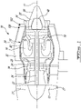
Fig. 1 is a schematic cross-sectional view of a turbofan engine having cooling system for cooling an electric machine, in accordance with one or more embodiments; -
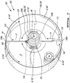
Fig. 2 is an oblique view of the cooling system ofFig. 1 , showing a coolant circuit having an evaporator, a condenser and conduits inside which a coolant fluid circulates, in accordance with one or more embodiments; -
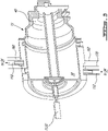
Fig. 3 is an oblique cross-sectional view of the evaporator ofFig. 2 , in accordance with one or more embodiments; and -
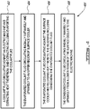
Fig. 4 is a flow chart of an example of a method of cooling an electric machine of a turbofan engine, in accordance with one or more embodiments. -
Fig. 1 illustrates aturbofan engine 10 of a type preferably provided for use in subsonic flight, generally comprising in serial flow communication afan 12 through which ambient air is propelled, acompressor section 14 for pressurizing the air, acombustor 16 in which the compressed air is mixed with fuel and ignited for generating an annular stream of hot combustion gases around theengine axis 11, aturbine section 18 for extracting energy from the combustion gases, and anexhaust section 20 where the hot combustion gases are expelled. - It is noted that the terms "radial", "annular" and "circumferential" used throughout the description and appended claims are defined with respect to the
engine axis 11. It is further noted that the terms "upper" and "lower" used throughout the description and appended claims are defined with respect to gravity when the aircraft is in typical cruising conditions. - In this example, the
turbofan engine 10 has anengine core 13 including a two spool arrangement provided by first andsecond shafts engine axis 11. Thefirst shaft 22 corresponds to alow pressure spool 26, and thesecond shaft 24 corresponds to ahigh pressure spool 24. Thefirst shaft 22 is coupled to a low pressure compressor section and a low pressure turbine section. Thesecond shaft 24 is coupled to a high pressure compressor section and a high pressure turbine section. Theshafts housing 30 of theengine core 13 for rotation and typically include multiple portions secured to one another, as is known in the art. - As shown, the
turbofan engine 10 generally has abypass duct 32 forming a bypass passage extending annularly around theengine axis 11. The bypass passage extends rearwardly from thefan 12 and around theengine core 13 towards theexhaust section 20. Thefan 12 hasmultiple blades 27 and is typically coupled to thefirst shaft 22. - As depicted, a
nozzle 36 is disposed in theexhaust section 20 downstream from the lowpressure turbine section 18, and atail cone 38 is arranged within thenozzle 36. In this example, anelectric machine 40 is disposed in theexhaust section 20 and coupled to a rotary shaft. Theelectric machine 40 may be directly or indirectly coupled to the rotary shaft. In some embodiments, a clutch can be used in the coupling. In this specific example, theelectric machine 40 is arranged within the tail cone 39 and driven by thefirst shaft 22. Theelectric machine 40 can provide a hybrid heat/electric functionality to theturbofan engine 10. In a first mode of operation, theelectric machine 40 can be driven by thefirst shaft 22 to generate electrical power for use by other components of theturbofan engine 10 or aircraft. In a second mode of operating, theelectric machine 40 can draw external electrical power from the remainder of theturbofan engine 10 or aircraft to drive thefirst shaft 22 to further propulsion. As theexhaust section 20 is an area where temperatures can rise significantly during operation of theturbofan engine 10, and theelectric machine 40 typically generates heat of its own during operation in either mode of operation, it is desirable to cool theelectric machine 40 from the combustion gases exiting thenozzle 36. - As shown, the
turbofan engine 10 is provided with acooling system 100 having acoolant circuit 102 extracting heat from theelectric machine 40 and releasing the extracted heat in the bypass passage. More specifically, and now referring toFig. 2 , thecoolant system 100 has acoolant circuit 102 having an evaporator 104 circumferentially disposed around at least part of theelectric machine 40 and in thermal communication with theelectric machine 40. Thecoolant circuit 102 also has a condenser 106 which has a surface cooler 108 circumferentially disposed around at least part of the bypass passage orduct 34 and in thermal communication with thebypass duct 34. As illustrated, afirst conduit 110 fluidly connecting an upper region 104a of the evaporator to anupper region 106a of the condenser 106 is provided. Asecond conduit 112 is also provided to fluidly connect alower region 106b of the condenser 106 to alower region 104b of the evaporator 104. Upon heating of theelectric machine 40, or more specifically heating ofoil 50 contained in theelectric machine 40 or from the hot combustion gases flowing annularly around the engine core, acoolant fluid 120 in thecoolant circuit 102 can conveniently extract heat from theelectric machine 40 and release the extracted heat in thebypass duct 34. More specifically, thecoolant fluid 120 circulating in the evaporator 104, against theelectric machine 40, extracts heat from theelectric machine 40 which contributes to evaporating thecoolant fluid 120. The evaporatedcoolant fluid 120 then circulates radially outwardly and upwardly to theupper region 106a of the condenser 106 via thefirst conduit 110. The evaporatedcoolant fluid 120 circulates circumferentially along the surface cooler 106 and releases the extracted heat which results in condensing of the evaporatedcoolant fluid 120. The condensedcoolant fluid 120 then circulates radially inwardly and upwardly from thelower region 112 of the condenser 106 towards theelectric machine 40 via thesecond conduit 112 where the cooling cycle described immediately above is repeated. Such a phase-change coolant cycle can be performed repetitively and simultaneously thereby cooling theelectric machine 40 during use. - It is noted that as some portion of the
coolant fluid 120 is evaporated in the evaporator 104, some other portion of thecoolant fluid 120 is condensed in the condenser 106 thereby provide a continuous and self-circulating cooling operation to thecooling circuit 102. In some embodiments, thecoolant fluid 120 circulating in thecoolant circuit 102 allows a set temperature to be maintained without pumps and minimum maintenance. Thecoolant fluid 120 sealingly enclosed within thecoolant circuit 102 self-circulates in a flow direction which is illustrated by the arrows A ofFig. 2 as soon as the heat generated by theelectric machine 40 is sufficient to evaporate, or equivalently boil, thecoolant fluid 120 into an evaporated fluid or vapor portion. Further, also required for self-circulation in the flow direction is the heat release potential of the condenser 106 which is preferably sufficient to condense all of the evaporated fluid into a condensed cooling fluid or liquid portion. In this way, the cooling fluid passively boils, flows and condenses repetitively in a number of cycles to transfer heat from a high temperature region, proximate theelectric machine 40, to a lower temperature region, proximate thebypass duct 34. Doing so, thecoolant fluid 120 undergoes a large volume change when it transforms from liquid to vapour phase, and subsequently back from vapour to liquid. Thecoolant system 100 takes advantage of the two-phase heat transfer available from thecoolant fluid 120 in thecoolant circuit 102, whichcoolant fluid 120 is preferably water in this embodiment, however any other suitable working fluid may be used. Water can be preferred in some embodiments as it has convenient boiling and condensation points, and has relatively high thermal conductivity relative to air and other conveniently available liquids. Water is also inexpensive and present no environmental hazards. In some embodiments, purified water can be preferred as purified water exhibits a high thermal conductivity and good cooling properties, has a low electrical conductivity when free of ions and is non-flammable, a property of significant importance especially as the cooling system is operated proximate hot combustion gases. Any other dielectric liquid can also be used in some other embodiments. Examples of such dielectric liquids can include, but are not limited to, purified water, mineral oil, silicone oil, Fluorinert™ FC-72, and the like. While these dielectric liquids can insulate the electric machine during operation, such dielectric liquids may also in some instances prevent or rapidly quench electric discharges that may occur proximate the electric machine. - In some embodiments, the
coolant circuit 102 has apump 140 in fluid communication with thecoolant circuit 102 for pumping thecoolant fluid 120 around thecoolant circuit 102, thereby forcing the circulation. As emphasized with dashed lines, thepump 140 is optional as it can be omitted in some embodiments. - The surface cooler 108 may be annular such as illustrated. However, the surface cooler can be semi-annular as well, as long as it somehow partially or wholly surrounds the
electric machine 40 along its circumference. When the surface cooler 108 is annular, the surface cooler 108 definescoolant paths 142 which are laterally opposite to one another relative the first andsecond conduits coolant paths 142 extend from theupper region 106a of the condenser 106 to thelower region 106b of the condenser 106 and extend circumferentially on respective sides of thebypass duct 34. In some embodiments, the surface cooler 106 is supported on an outer bypass duct wall or on an inner bypass duct wall. An example of such a surface cooler is described in Applicant'sU.S. Pat. No. 7,377,100 , which is hereby incorporated by reference in this disclosure. A fluid fill/gauge can be located for easy access on the surface cooler 108 in some embodiments. - Still referring to
Fig. 2 , the evaporator 104 has a surface heater 150 circumferentially disposed around at least part of theelectric machine 40 and in thermal communication with theelectric machine 40. The surface heater 150 may be annular such as illustrated. However, the surface heater 150 can be semi-annular as well, as long as it somehow partially or wholly surrounds theelectric machine 40 along its circumference. As shown, the surface heater 150 definesheating paths 152 which are laterally opposite to one another relative the first andsecond conduits heating paths 152 extend from thelower region 104b of the evaporator 104 to the upper region 104a of the evaporator 104 and extend circumferentially on respective sides of theelectric machine 40. As depicted in this specific embodiment, the surface cooler 108 and the surface heater 150 have an axis coinciding with one another, and also coinciding with theengine axis 11. However, in some other embodiments, the axes of the surface cooler 108 and surface heater 150 may not coincide with one another. The surface cooler and the surface heater can extend circumferentially relative theengine axis 11. - Referring now to
Fig. 3 , the turbofan engine may have at least first andsecond struts engine core 13 and thebypass duct 34. Preferably, the first andsecond conduits second struts second struts second conduits second struts second conduits power cable 170 electrically coupling theelectric machine 40 may be provided. Power may be generated by theelectric machine 40 in the first mode of operation whereas power may be brought to theelectric machine 40 in the second mode of operation. In either mode of operation, thepower cable 170 may generate heat by itself. In such embodiments, it may be desirable to dispose thepower cable 170 alongside thesecond conduit 112, the one carrying the condensed, cold coolant liquid, within or alongside thesecond strut 162. In such embodiments, thecondensed coolant fluid 120 can extract heat from thepower cable 170 as thecondensed coolant fluid 120 circulates radially inwardly and upwardly from thelower region 106b of the surface cooler 106 to theelectric machine 40. In an alternate embodiment, thepower cable 170 can extend within the corresponding one of the first andsecond conduits -
Fig. 4 shows a method of cooling an electric machine of a turbofan engine. - As shown, as per
step 402, a coolant fluid circulates against the electric machine and extracts heat from the electric machine. The extracting includes evaporating the coolant fluid. - A
step 404, the evaporated coolant fluid circulates radially outwardly and upwardly to an upper region of the surface cooler. - At
step 406, the evaporated coolant fluid circulates circumferentially along the surface cooler and releases the extracted heat thereto. The releasing includes condensing the evaporated coolant fluid. - At
step 408, the condensed coolant fluid circulates radially inwardly and upwardly from a lower region of the surface cooler to the electric machine. - In some embodiments, the steps of circulating includes actively driving the circulating using at least a pump. The pump can be in fluid communication with the condenser, the evaporator, the first and second conduits, or a combination thereof, depending on the embodiment. The pump can be powered by the electric machine in some embodiments. However, in some other embodiments, the pump can be powered using a power source external to the electric machine. The pump can be omitted in at least some embodiments. As discussed above, the coolant fluid can be an dielectric material electrically insulating the electric machine during use.
- The embodiments described in this document provide non-limiting examples of possible implementations of the present technology. Upon review of the present disclosure, a person of ordinary skill in the art will recognize that changes may be made to the embodiments described herein without departing from the scope of the present technology. For instance, in the example presented and illustrated above, the condenser is in thermal contact with a bypass duct, and configured for thermal exchange with an annular flow of air circulating in a bypass passage formed between the bypass duct and the engine core, where the air mover is a fan of the turbofan and the bypass duct is radially external to the annular flow of air. In an alternate embodiment, the air mover can be a propeller generating an annular flow of air around a nacelle of the engine, and the condenser can be in thermal contact with the nacelle, and configured for thermal exchange with the annular flow of air incoming around the nacelle from the propeller, in which case the condenser can be radially internal to the flow of air. Indeed, a nacelle can form a surface extending around the rotation axis of a propeller and which is designed to facilitate the flow of air around the engine, and preserve its energy for propulsion, in a way similar to how a bypass duct extends around the rotation axis of a fan and is designed to facilitate the flow of air around the core engine and preserve its energy for propulsion. The gas turbine engine can thus be a turboprop, an electric engine, or a piston engine, for example. Yet further modifications could be implemented by a person of ordinary skill in the art in view of the present disclosure, which modifications would be within the scope of the present technology.
Claims (15)
- A cooling system (100) for an engine (10) having an air mover (12) configured for generating a flow of air around a rotation axis (11), a surface (34) extending around the rotation axis delimiting a passage (32) for the flow of air downstream of the air mover (12), and an electric machine (40) disposed within the surface (34) and coupled to the air mover (12), the cooling system (100) comprising:a coolant circuit (102) having:an evaporator (104) circumferentially disposed around at least part of the electric machine (40) and in thermal communication therewith;a condenser (106) having a surface cooler (108) circumferentially disposed around at least part of the bypass duct (34) and in thermal communication therewith;a first conduit (110) fluidly connecting an upper region (104a) of the evaporator (104) to an upper region (106a) of the condenser (106); anda second conduit (112) fluidly connecting a lower region (106b) of the condenser (106) to a lower region (104b) of the evaporator (104); anda coolant fluid (120) in the coolant circuit (102).
- The cooling system (100) of claim 1 wherein the coolant circuit (102) has a pumping device (140) in fluid communication therewith, the pumping device (140) being configured for pumping the coolant fluid (120) in the coolant circuit (102).
- The cooling system (100) of claims 1 or 2 wherein the surface cooler (108) defines coolant paths (142) opposite to one another, extending from the upper region (106a) of the condenser (106a) to the lower region (106b) of the condenser (106) and circumferentially disposed around at least part of corresponding sides of the surface (34).
- The cooling system (100) of any preceding claim wherein the evaporator (104) has a surface heater (150) disposed at least partially around the electric machine (40) and in thermal communication therewith and wherein, optionally, the surface cooler (108) and the surface heater (150) extend circumferentially relative to the rotation axis (11).
- The cooling system (100) of claim 4 wherein the surface heater (150) defines heating paths (152) opposite to one another, extending from the lower region (104b) of the evaporator (104) to an upper region (104a) of the evaporator (104) and circumferentially disposed around at least part of corresponding sides of the electric machine (40).
- The cooling system (10) of any preceding claim wherein the coolant fluid (120) is a dielectric material.
- A gas turbine engine (10) comprising:an air mover (12) configured for generating a flow of air around a rotation axis (11);a surface (34) extending around the rotation axis (11) delimiting a passage (32) for the flow of air downstream of the air mover (12);an electric machine (40) disposed within the passage (32) and coupled to the air mover (12);the cooling system (100) of any preceding claim.
- The gas turbine engine (10) of claims 7 further comprising a bypass duct (34) annularly extending around the passage (32), the passage extending rearwardly from a fan (12) and around an engine core (13), the engine core (13) having an exhaust section (20) and at least one rotary shaft (22) disposed along the rotation axis (11), the electric machine (40) being disposed in the exhaust section (20) and being coupled to the rotary shaft (22).
- The gas turbine engine (10) of claim 8 further comprising at least first and second struts (160,162) radially extending between the engine core (10) and the bypass duct (34), the first and second conduits (110,112) running along a respective one of the first and second struts (160,162).
- The gas turbine engine (10) of claim 9 further comprising a power cable (170) electrically coupling the electric machine (40) to an electric device external to the engine core (13), the power cable (170) running along at least one of the first and second struts (160,162) and being in thermal communication with a corresponding one of the first and second conduits (110,112).
- The gas turbine engine (10) of claim 10 wherein the power cable (170) runs along the second conduit (112) and is in thermal communication therewith.
- A method of cooling an electric machine (40) of a gas turbine engine (10) having an air mover (12) configured for generating a flow of air around a rotation axis (11), a surface (34) extending around the rotation axis (11) delimiting a passage (32) for the flow of air downstream of the air mover (12), and an electric machine (40) disposed within the surface (34) and coupled to the air mover (12), the method comprising:circulating a coolant fluid (120) against the electric machine (40) and extracting heat therefrom, said extracting including evaporating the coolant fluid (120);circulating the evaporated coolant fluid (120) radially outwardly and upwardly to an upper region of the surface cooler (108);circulating the evaporated coolant fluid (120) circumferentially along the surface cooler (108) and releasing the extracted heat thereto, said releasing including condensing the evaporated coolant fluid (120); andcirculating the condensed coolant fluid (120) radially inwardly and upwardly from a lower region of the surface cooler (108) to the electric machine (40).
- The method of claim 12 wherein said circulating includes actively driving the circulating using a pump (140).
- The method of claims 12 or 13 wherein said coolant fluid (120) is a dielectric material electrically insulating the electric machine (40).
- The method of any of claims 12 to 14 wherein the condensed coolant fluid (120) extracts heat from a power cable (170) electrically coupling the electric machine (40) to an external electric device as the condensed coolant fluid (120) circulates radially inwardly and upwardly from the lower region of the surface cooler (108) to the electric machine (40).
Applications Claiming Priority (1)
| Application Number | Priority Date | Filing Date | Title |
|---|---|---|---|
| US17/349,369 US11674441B2 (en) | 2021-06-16 | 2021-06-16 | Turbofan engine, cooling system and method of cooling an electric machine |
Publications (2)
| Publication Number | Publication Date |
|---|---|
| EP4105464A1 true EP4105464A1 (en) | 2022-12-21 |
| EP4105464B1 EP4105464B1 (en) | 2025-05-14 |
Family
ID=82117083
Family Applications (1)
| Application Number | Title | Priority Date | Filing Date |
|---|---|---|---|
| EP22179486.0A Active EP4105464B1 (en) | 2021-06-16 | 2022-06-16 | Turbofan engine, cooling system and method of cooling an electric machine |
Country Status (3)
| Country | Link |
|---|---|
| US (1) | US11674441B2 (en) |
| EP (1) | EP4105464B1 (en) |
| CA (1) | CA3161021A1 (en) |
Families Citing this family (10)
| Publication number | Priority date | Publication date | Assignee | Title |
|---|---|---|---|---|
| US20240254898A1 (en) * | 2023-01-27 | 2024-08-01 | Raytneon Technologies Corporation | Power electronics waste heat recovery in recuperation cycle |
| US12188414B2 (en) * | 2023-02-17 | 2025-01-07 | General Electric Company | Reverse flow gas turbine engine having electric machine |
| EP4417796B1 (en) * | 2023-02-17 | 2026-03-04 | General Electric Company | Reverse flow gas turbine engine having electric machine |
| US12416262B2 (en) | 2023-02-17 | 2025-09-16 | General Electric Company | Reverse flow gas turbine engine having electric machine |
| US12319417B2 (en) | 2023-02-17 | 2025-06-03 | General Electric Company | Reverse flow gas turbine engine having electric machine |
| US20260185479A1 (en) * | 2023-02-17 | 2026-07-02 | General Electric Company | Reverse flow gas turbine engine having electric machine |
| US12366201B2 (en) | 2023-02-17 | 2025-07-22 | General Electric Company | Reverse flow gas turbine engine having electric machine |
| US12460576B2 (en) * | 2023-02-17 | 2025-11-04 | General Electric Company | Reverse flow gas turbine engine having electric machine |
| US12510025B2 (en) | 2023-02-17 | 2025-12-30 | General Electric Company | Reverse flow gas turbine engine having electric machine |
| US12486797B2 (en) * | 2023-02-17 | 2025-12-02 | General Electric Company | Reverse flow gas turbine engine having electric machine |
Citations (3)
| Publication number | Priority date | Publication date | Assignee | Title |
|---|---|---|---|---|
| US7377100B2 (en) | 2004-08-27 | 2008-05-27 | Pratt & Whitney Canada Corp. | Bypass duct fluid cooler |
| US20180050807A1 (en) * | 2016-08-22 | 2018-02-22 | General Electric Company | Electric propulsion system |
| US20190014687A1 (en) * | 2017-07-10 | 2019-01-10 | Rolls-Royce North American Technologies, Inc. | Cooling system in hybrid electric propulsion gas turbine engine |
Family Cites Families (7)
| Publication number | Priority date | Publication date | Assignee | Title |
|---|---|---|---|---|
| US10071811B2 (en) * | 2016-08-22 | 2018-09-11 | General Electric Company | Embedded electric machine |
| US11060457B2 (en) | 2016-12-02 | 2021-07-13 | Pratt & Whitney Canada Corp. | Cooling system and method for gas turbine engine |
| US11371379B2 (en) * | 2017-08-22 | 2022-06-28 | General Electric Company | Turbomachine with alternatingly spaced turbine rotor blades |
| US10801410B2 (en) | 2018-04-12 | 2020-10-13 | Raytheon Technologies Corporation | Thermal management of tail cone mounted generator |
| US10784750B2 (en) | 2018-06-12 | 2020-09-22 | General Electric Company | Electric motor having an integrated cooling system and methods of cooling an electric motor |
| US11130582B2 (en) | 2018-08-03 | 2021-09-28 | Rolls-Royce Corporation | Systems and methods of optimizing cooling and providing useful heating from single phase and two phase heat management in propulsion systems |
| WO2021014667A1 (en) | 2019-07-24 | 2021-01-28 | 株式会社Ihi | Generator cooling system of turbo fan engine |
-
2021
- 2021-06-16 US US17/349,369 patent/US11674441B2/en active Active
-
2022
- 2022-05-27 CA CA3161021A patent/CA3161021A1/en active Pending
- 2022-06-16 EP EP22179486.0A patent/EP4105464B1/en active Active
Patent Citations (3)
| Publication number | Priority date | Publication date | Assignee | Title |
|---|---|---|---|---|
| US7377100B2 (en) | 2004-08-27 | 2008-05-27 | Pratt & Whitney Canada Corp. | Bypass duct fluid cooler |
| US20180050807A1 (en) * | 2016-08-22 | 2018-02-22 | General Electric Company | Electric propulsion system |
| US20190014687A1 (en) * | 2017-07-10 | 2019-01-10 | Rolls-Royce North American Technologies, Inc. | Cooling system in hybrid electric propulsion gas turbine engine |
Also Published As
| Publication number | Publication date |
|---|---|
| US11674441B2 (en) | 2023-06-13 |
| EP4105464B1 (en) | 2025-05-14 |
| CA3161021A1 (en) | 2022-12-16 |
| US20220403782A1 (en) | 2022-12-22 |
Similar Documents
| Publication | Publication Date | Title |
|---|---|---|
| EP4105464B1 (en) | Turbofan engine, cooling system and method of cooling an electric machine | |
| CN106884723B (en) | The closed loop cooling means and system of gas-turbine unit are used for using heat pipe | |
| JP5226981B2 (en) | Heat transfer device for turbine engine using heat pipe | |
| US9765694B2 (en) | Gas turbine engine heat exchangers and methods of assembling the same | |
| EP2971737B1 (en) | Intercooled gas turbine with closed combined power cycle | |
| EP3239479A1 (en) | Fluid cooling system for a gas turbine engine and corresponding gas turbine engine | |
| US20180023416A1 (en) | Systems and methods for cooling components within a gas turbine engine | |
| US10526963B2 (en) | Cooling of turbine engine by evaporation | |
| CA2949678A1 (en) | Intercooling system and method for a gas turbine engine | |
| JP7608139B2 (en) | Systems and methods for operating a turbocharged gas turbine engine - Patents.com | |
| CN106917683B (en) | Gas-turbine unit and cooling system for it | |
| EP4411122A2 (en) | A propulsion system for an aircraft | |
| US20070022732A1 (en) | Methods and apparatus for operating gas turbine engines | |
| CA2509788A1 (en) | Foreign object damage tolerant nacelle anti-icing system | |
| CN117367186A (en) | Heat exchanger for hydrogen fuel delivery system | |
| BR102016028337A2 (en) | COOLING METHOD OF A GAS TURBINE ENGINE | |
| CN116917599A (en) | Hybrid turbofan engine for aircraft including motor/generator cooled by heat pipes | |
| EP3244039A1 (en) | Heat exchange system for a power gearbox, a power and a turbo engine with a power gearbox | |
| CN106414902B (en) | Heat pipe temperature management system for impellers and vanes in turbines | |
| EP4650582A1 (en) | Cooling system for cooling an automotive component | |
| RU2076936C1 (en) | Turbocompressor engine and method to increase its economy |
Legal Events
| Date | Code | Title | Description |
|---|---|---|---|
| PUAI | Public reference made under article 153(3) epc to a published international application that has entered the european phase |
Free format text: ORIGINAL CODE: 0009012 |
|
| STAA | Information on the status of an ep patent application or granted ep patent |
Free format text: STATUS: THE APPLICATION HAS BEEN PUBLISHED |
|
| AK | Designated contracting states |
Kind code of ref document: A1 Designated state(s): AL AT BE BG CH CY CZ DE DK EE ES FI FR GB GR HR HU IE IS IT LI LT LU LV MC MK MT NL NO PL PT RO RS SE SI SK SM TR |
|
| STAA | Information on the status of an ep patent application or granted ep patent |
Free format text: STATUS: REQUEST FOR EXAMINATION WAS MADE |
|
| 17P | Request for examination filed |
Effective date: 20230621 |
|
| RBV | Designated contracting states (corrected) |
Designated state(s): AL AT BE BG CH CY CZ DE DK EE ES FI FR GB GR HR HU IE IS IT LI LT LU LV MC MK MT NL NO PL PT RO RS SE SI SK SM TR |
|
| GRAP | Despatch of communication of intention to grant a patent |
Free format text: ORIGINAL CODE: EPIDOSNIGR1 |
|
| STAA | Information on the status of an ep patent application or granted ep patent |
Free format text: STATUS: GRANT OF PATENT IS INTENDED |
|
| INTG | Intention to grant announced |
Effective date: 20241203 |
|
| GRAS | Grant fee paid |
Free format text: ORIGINAL CODE: EPIDOSNIGR3 |
|
| GRAA | (expected) grant |
Free format text: ORIGINAL CODE: 0009210 |
|
| STAA | Information on the status of an ep patent application or granted ep patent |
Free format text: STATUS: THE PATENT HAS BEEN GRANTED |
|
| AK | Designated contracting states |
Kind code of ref document: B1 Designated state(s): AL AT BE BG CH CY CZ DE DK EE ES FI FR GB GR HR HU IE IS IT LI LT LU LV MC MK MT NL NO PL PT RO RS SE SI SK SM TR |
|
| REG | Reference to a national code |
Ref country code: GB Ref legal event code: FG4D |
|
| REG | Reference to a national code |
Ref country code: CH Ref legal event code: EP |
|
| REG | Reference to a national code |
Ref country code: IE Ref legal event code: FG4D |
|
| REG | Reference to a national code |
Ref country code: DE Ref legal event code: R096 Ref document number: 602022014538 Country of ref document: DE |
|
| PGFP | Annual fee paid to national office [announced via postgrant information from national office to epo] |
Ref country code: AT Payment date: 20250721 Year of fee payment: 4 |
|
| REG | Reference to a national code |
Ref country code: NL Ref legal event code: MP Effective date: 20250514 |
|
| PG25 | Lapsed in a contracting state [announced via postgrant information from national office to epo] |
Ref country code: FI Free format text: LAPSE BECAUSE OF FAILURE TO SUBMIT A TRANSLATION OF THE DESCRIPTION OR TO PAY THE FEE WITHIN THE PRESCRIBED TIME-LIMIT Effective date: 20250514 Ref country code: PT Free format text: LAPSE BECAUSE OF FAILURE TO SUBMIT A TRANSLATION OF THE DESCRIPTION OR TO PAY THE FEE WITHIN THE PRESCRIBED TIME-LIMIT Effective date: 20250915 Ref country code: ES Free format text: LAPSE BECAUSE OF FAILURE TO SUBMIT A TRANSLATION OF THE DESCRIPTION OR TO PAY THE FEE WITHIN THE PRESCRIBED TIME-LIMIT Effective date: 20250514 |
|
| REG | Reference to a national code |
Ref country code: LT Ref legal event code: MG9D |
|
| PG25 | Lapsed in a contracting state [announced via postgrant information from national office to epo] |
Ref country code: NO Free format text: LAPSE BECAUSE OF FAILURE TO SUBMIT A TRANSLATION OF THE DESCRIPTION OR TO PAY THE FEE WITHIN THE PRESCRIBED TIME-LIMIT Effective date: 20250814 Ref country code: GR Free format text: LAPSE BECAUSE OF FAILURE TO SUBMIT A TRANSLATION OF THE DESCRIPTION OR TO PAY THE FEE WITHIN THE PRESCRIBED TIME-LIMIT Effective date: 20250815 |
|
| PG25 | Lapsed in a contracting state [announced via postgrant information from national office to epo] |
Ref country code: NL Free format text: LAPSE BECAUSE OF FAILURE TO SUBMIT A TRANSLATION OF THE DESCRIPTION OR TO PAY THE FEE WITHIN THE PRESCRIBED TIME-LIMIT Effective date: 20250514 Ref country code: PL Free format text: LAPSE BECAUSE OF FAILURE TO SUBMIT A TRANSLATION OF THE DESCRIPTION OR TO PAY THE FEE WITHIN THE PRESCRIBED TIME-LIMIT Effective date: 20250514 |
|
| REG | Reference to a national code |
Ref country code: AT Ref legal event code: MK05 Ref document number: 1794941 Country of ref document: AT Kind code of ref document: T Effective date: 20250514 |
|
| PG25 | Lapsed in a contracting state [announced via postgrant information from national office to epo] |
Ref country code: BG Free format text: LAPSE BECAUSE OF FAILURE TO SUBMIT A TRANSLATION OF THE DESCRIPTION OR TO PAY THE FEE WITHIN THE PRESCRIBED TIME-LIMIT Effective date: 20250514 |
|
| PG25 | Lapsed in a contracting state [announced via postgrant information from national office to epo] |
Ref country code: AT Free format text: LAPSE BECAUSE OF FAILURE TO SUBMIT A TRANSLATION OF THE DESCRIPTION OR TO PAY THE FEE WITHIN THE PRESCRIBED TIME-LIMIT Effective date: 20250514 Ref country code: HR Free format text: LAPSE BECAUSE OF FAILURE TO SUBMIT A TRANSLATION OF THE DESCRIPTION OR TO PAY THE FEE WITHIN THE PRESCRIBED TIME-LIMIT Effective date: 20250514 |
|
| PG25 | Lapsed in a contracting state [announced via postgrant information from national office to epo] |
Ref country code: RS Free format text: LAPSE BECAUSE OF FAILURE TO SUBMIT A TRANSLATION OF THE DESCRIPTION OR TO PAY THE FEE WITHIN THE PRESCRIBED TIME-LIMIT Effective date: 20250814 |
|
| PG25 | Lapsed in a contracting state [announced via postgrant information from national office to epo] |
Ref country code: IS Free format text: LAPSE BECAUSE OF FAILURE TO SUBMIT A TRANSLATION OF THE DESCRIPTION OR TO PAY THE FEE WITHIN THE PRESCRIBED TIME-LIMIT Effective date: 20250914 |
|
| PG25 | Lapsed in a contracting state [announced via postgrant information from national office to epo] |
Ref country code: LV Free format text: LAPSE BECAUSE OF FAILURE TO SUBMIT A TRANSLATION OF THE DESCRIPTION OR TO PAY THE FEE WITHIN THE PRESCRIBED TIME-LIMIT Effective date: 20250514 |
|
| PG25 | Lapsed in a contracting state [announced via postgrant information from national office to epo] |
Ref country code: DK Free format text: LAPSE BECAUSE OF FAILURE TO SUBMIT A TRANSLATION OF THE DESCRIPTION OR TO PAY THE FEE WITHIN THE PRESCRIBED TIME-LIMIT Effective date: 20250514 Ref country code: SM Free format text: LAPSE BECAUSE OF FAILURE TO SUBMIT A TRANSLATION OF THE DESCRIPTION OR TO PAY THE FEE WITHIN THE PRESCRIBED TIME-LIMIT Effective date: 20250514 |
|
| PG25 | Lapsed in a contracting state [announced via postgrant information from national office to epo] |
Ref country code: CZ Free format text: LAPSE BECAUSE OF FAILURE TO SUBMIT A TRANSLATION OF THE DESCRIPTION OR TO PAY THE FEE WITHIN THE PRESCRIBED TIME-LIMIT Effective date: 20250514 |
|
| PG25 | Lapsed in a contracting state [announced via postgrant information from national office to epo] |
Ref country code: EE Free format text: LAPSE BECAUSE OF FAILURE TO SUBMIT A TRANSLATION OF THE DESCRIPTION OR TO PAY THE FEE WITHIN THE PRESCRIBED TIME-LIMIT Effective date: 20250514 |
|
| PG25 | Lapsed in a contracting state [announced via postgrant information from national office to epo] |
Ref country code: SK Free format text: LAPSE BECAUSE OF FAILURE TO SUBMIT A TRANSLATION OF THE DESCRIPTION OR TO PAY THE FEE WITHIN THE PRESCRIBED TIME-LIMIT Effective date: 20250514 |
|
| REG | Reference to a national code |
Ref country code: CH Ref legal event code: H13 Free format text: ST27 STATUS EVENT CODE: U-0-0-H10-H13 (AS PROVIDED BY THE NATIONAL OFFICE) Effective date: 20260127 |
|
| PG25 | Lapsed in a contracting state [announced via postgrant information from national office to epo] |
Ref country code: IT Free format text: LAPSE BECAUSE OF FAILURE TO SUBMIT A TRANSLATION OF THE DESCRIPTION OR TO PAY THE FEE WITHIN THE PRESCRIBED TIME-LIMIT Effective date: 20250514 |
|
| PG25 | Lapsed in a contracting state [announced via postgrant information from national office to epo] |
Ref country code: RO Free format text: LAPSE BECAUSE OF FAILURE TO SUBMIT A TRANSLATION OF THE DESCRIPTION OR TO PAY THE FEE WITHIN THE PRESCRIBED TIME-LIMIT Effective date: 20250514 |
|
| PG25 | Lapsed in a contracting state [announced via postgrant information from national office to epo] |
Ref country code: LU Free format text: LAPSE BECAUSE OF NON-PAYMENT OF DUE FEES Effective date: 20250616 |
|
| REG | Reference to a national code |
Ref country code: DE Ref legal event code: R097 Ref document number: 602022014538 Country of ref document: DE |
|
| PG25 | Lapsed in a contracting state [announced via postgrant information from national office to epo] |
Ref country code: MC Free format text: LAPSE BECAUSE OF FAILURE TO SUBMIT A TRANSLATION OF THE DESCRIPTION OR TO PAY THE FEE WITHIN THE PRESCRIBED TIME-LIMIT Effective date: 20250514 |
|
| REG | Reference to a national code |
Ref country code: BE Ref legal event code: MM Effective date: 20250630 |
|
| PLBE | No opposition filed within time limit |
Free format text: ORIGINAL CODE: 0009261 |
|
| STAA | Information on the status of an ep patent application or granted ep patent |
Free format text: STATUS: NO OPPOSITION FILED WITHIN TIME LIMIT |
|
| REG | Reference to a national code |
Ref country code: CH Ref legal event code: L10 Free format text: ST27 STATUS EVENT CODE: U-0-0-L10-L00 (AS PROVIDED BY THE NATIONAL OFFICE) Effective date: 20260325 |
|
| PG25 | Lapsed in a contracting state [announced via postgrant information from national office to epo] |
Ref country code: IE Free format text: LAPSE BECAUSE OF NON-PAYMENT OF DUE FEES Effective date: 20250616 |
|
| PG25 | Lapsed in a contracting state [announced via postgrant information from national office to epo] |
Ref country code: BE Free format text: LAPSE BECAUSE OF NON-PAYMENT OF DUE FEES Effective date: 20250630 |
|
| 26N | No opposition filed |
Effective date: 20260217 |
|
| PG25 | Lapsed in a contracting state [announced via postgrant information from national office to epo] |
Ref country code: CH Free format text: LAPSE BECAUSE OF NON-PAYMENT OF DUE FEES Effective date: 20250630 |
|
| PG25 | Lapsed in a contracting state [announced via postgrant information from national office to epo] |
Ref country code: LT Free format text: LAPSE BECAUSE OF FAILURE TO SUBMIT A TRANSLATION OF THE DESCRIPTION OR TO PAY THE FEE WITHIN THE PRESCRIBED TIME-LIMIT Effective date: 20250514 |
|
| PGFP | Annual fee paid to national office [announced via postgrant information from national office to epo] |
Ref country code: GB Payment date: 20260520 Year of fee payment: 5 |
|
| PGFP | Annual fee paid to national office [announced via postgrant information from national office to epo] |
Ref country code: DE Payment date: 20260520 Year of fee payment: 5 |
|
| PGFP | Annual fee paid to national office [announced via postgrant information from national office to epo] |
Ref country code: FR Payment date: 20260520 Year of fee payment: 5 |
|
| PG25 | Lapsed in a contracting state [announced via postgrant information from national office to epo] |
Ref country code: SE Free format text: LAPSE BECAUSE OF FAILURE TO SUBMIT A TRANSLATION OF THE DESCRIPTION OR TO PAY THE FEE WITHIN THE PRESCRIBED TIME-LIMIT Effective date: 20250514 Ref country code: CY Free format text: LAPSE BECAUSE OF FAILURE TO SUBMIT A TRANSLATION OF THE DESCRIPTION OR TO PAY THE FEE WITHIN THE PRESCRIBED TIME-LIMIT Effective date: 20250514 |