EP4105459A2 - Hybrid generator with detachable power unit and panel integration - Google Patents
Hybrid generator with detachable power unit and panel integration Download PDFInfo
- Publication number
- EP4105459A2 EP4105459A2 EP22173751.3A EP22173751A EP4105459A2 EP 4105459 A2 EP4105459 A2 EP 4105459A2 EP 22173751 A EP22173751 A EP 22173751A EP 4105459 A2 EP4105459 A2 EP 4105459A2
- Authority
- EP
- European Patent Office
- Prior art keywords
- generator
- battery
- circuit
- module
- mode
- Prior art date
- Legal status (The legal status is an assumption and is not a legal conclusion. Google has not performed a legal analysis and makes no representation as to the accuracy of the status listed.)
- Granted
Links
Images




Classifications
-
- H—ELECTRICITY
- H02—GENERATION; CONVERSION OR DISTRIBUTION OF ELECTRIC POWER
- H02J—ELECTRIC POWER NETWORKS; CIRCUIT ARRANGEMENTS OR SYSTEMS FOR SUPPLYING OR DISTRIBUTING ELECTRIC POWER; SYSTEMS FOR STORING ELECTRIC ENERGY
- H02J7/00—Circuit arrangements for charging or discharging batteries or for supplying loads from batteries
- H02J7/14—Circuit arrangements for charging or discharging batteries or for supplying loads from batteries for charging batteries from dynamo-electric generators driven at varying speed, e.g. on vehicle
- H02J7/1415—Circuit arrangements for charging or discharging batteries or for supplying loads from batteries for charging batteries from dynamo-electric generators driven at varying speed, e.g. on vehicle with a generator driven by a prime mover other than the motor of a vehicle
-
- H—ELECTRICITY
- H02—GENERATION; CONVERSION OR DISTRIBUTION OF ELECTRIC POWER
- H02J—ELECTRIC POWER NETWORKS; CIRCUIT ARRANGEMENTS OR SYSTEMS FOR SUPPLYING OR DISTRIBUTING ELECTRIC POWER; SYSTEMS FOR STORING ELECTRIC ENERGY
- H02J7/00—Circuit arrangements for charging or discharging batteries or for supplying loads from batteries
- H02J7/14—Circuit arrangements for charging or discharging batteries or for supplying loads from batteries for charging batteries from dynamo-electric generators driven at varying speed, e.g. on vehicle
-
- H—ELECTRICITY
- H02—GENERATION; CONVERSION OR DISTRIBUTION OF ELECTRIC POWER
- H02J—ELECTRIC POWER NETWORKS; CIRCUIT ARRANGEMENTS OR SYSTEMS FOR SUPPLYING OR DISTRIBUTING ELECTRIC POWER; SYSTEMS FOR STORING ELECTRIC ENERGY
- H02J7/00—Circuit arrangements for charging or discharging batteries or for supplying loads from batteries
- H02J7/70—Circuit arrangements for charging or discharging batteries or for supplying loads from batteries characterised by the mechanical construction
-
- F—MECHANICAL ENGINEERING; LIGHTING; HEATING; WEAPONS; BLASTING
- F02—COMBUSTION ENGINES; HOT-GAS OR COMBUSTION-PRODUCT ENGINE PLANTS
- F02B—INTERNAL-COMBUSTION PISTON ENGINES; COMBUSTION ENGINES IN GENERAL
- F02B63/00—Adaptations of engines for driving pumps, hand-held tools or electric generators; Portable combinations of engines with engine-driven devices
- F02B63/04—Adaptations of engines for driving pumps, hand-held tools or electric generators; Portable combinations of engines with engine-driven devices for electric generators
- F02B63/044—Adaptations of engines for driving pumps, hand-held tools or electric generators; Portable combinations of engines with engine-driven devices for electric generators the engine-generator unit being placed on a frame or in an housing
- F02B63/047—Movable engine-generator combinations on wheels
-
- H—ELECTRICITY
- H02—GENERATION; CONVERSION OR DISTRIBUTION OF ELECTRIC POWER
- H02J—ELECTRIC POWER NETWORKS; CIRCUIT ARRANGEMENTS OR SYSTEMS FOR SUPPLYING OR DISTRIBUTING ELECTRIC POWER; SYSTEMS FOR STORING ELECTRIC ENERGY
- H02J7/00—Circuit arrangements for charging or discharging batteries or for supplying loads from batteries
- H02J7/14—Circuit arrangements for charging or discharging batteries or for supplying loads from batteries for charging batteries from dynamo-electric generators driven at varying speed, e.g. on vehicle
- H02J7/1438—Circuit arrangements for charging or discharging batteries or for supplying loads from batteries for charging batteries from dynamo-electric generators driven at varying speed, e.g. on vehicle in combination with power supplies for loads other than batteries
-
- H—ELECTRICITY
- H02—GENERATION; CONVERSION OR DISTRIBUTION OF ELECTRIC POWER
- H02J—ELECTRIC POWER NETWORKS; CIRCUIT ARRANGEMENTS OR SYSTEMS FOR SUPPLYING OR DISTRIBUTING ELECTRIC POWER; SYSTEMS FOR STORING ELECTRIC ENERGY
- H02J7/00—Circuit arrangements for charging or discharging batteries or for supplying loads from batteries
- H02J7/80—Circuit arrangements for charging or discharging batteries or for supplying loads from batteries including monitoring or indicating arrangements
- H02J7/82—Control of state of charge [SOC]
-
- H—ELECTRICITY
- H02—GENERATION; CONVERSION OR DISTRIBUTION OF ELECTRIC POWER
- H02J—ELECTRIC POWER NETWORKS; CIRCUIT ARRANGEMENTS OR SYSTEMS FOR SUPPLYING OR DISTRIBUTING ELECTRIC POWER; SYSTEMS FOR STORING ELECTRIC ENERGY
- H02J7/00—Circuit arrangements for charging or discharging batteries or for supplying loads from batteries
- H02J7/855—Circuit arrangements for charging or discharging batteries or for supplying loads from batteries with circuits adapted for supplying loads from the battery
-
- H—ELECTRICITY
- H02—GENERATION; CONVERSION OR DISTRIBUTION OF ELECTRIC POWER
- H02J—ELECTRIC POWER NETWORKS; CIRCUIT ARRANGEMENTS OR SYSTEMS FOR SUPPLYING OR DISTRIBUTING ELECTRIC POWER; SYSTEMS FOR STORING ELECTRIC ENERGY
- H02J2207/00—Details of circuit arrangements for charging or discharging batteries or supplying loads from batteries
- H02J2207/20—Charging or discharging characterised by the power electronics converter
-
- H—ELECTRICITY
- H02—GENERATION; CONVERSION OR DISTRIBUTION OF ELECTRIC POWER
- H02J—ELECTRIC POWER NETWORKS; CIRCUIT ARRANGEMENTS OR SYSTEMS FOR SUPPLYING OR DISTRIBUTING ELECTRIC POWER; SYSTEMS FOR STORING ELECTRIC ENERGY
- H02J3/00—Circuit arrangements for AC mains or AC distribution networks
- H02J3/28—Arrangements for balancing of the load in networks by storage of energy
- H02J3/32—Arrangements for balancing of the load in networks by storage of energy using batteries or super capacitors with converting means
Definitions
- the present application relates generally to a hybrid generator with a detachable power unit and integration into a wall panel.
- An engine-generator set which may be referred to as a generator or a genset, may include an engine and an alternator or another device for generating electrical energy or power.
- One or more generators may provide electrical power to a load through a power bus.
- the power bus which may be referred to as a generator bus or common bus, transfers the electrical power from the engine-generator set to a load.
- the electrical load on the engine-generator set may vary over time and challenges remain in providing an efficient generator that can adapt to varying loads.
- the following embodiments include an engine-generator set, which may be referred to as a generator or a genset, and may include an engine and an alternator.
- the alternator of the genset is an example electric machine.
- the alternator may include permanent magnets for the exciter of the generator or the main generator or the exciter.
- the generator may include a wound rotor generator with a permanent magnet exciter, the electrical machine may also act as a motor as well.
- Other embodiments of electrical machines include permanent magnet brush-type direct current (DC) machines, permanent magnet brushless DC machines, series-wound or universal machines, induction alternating current (AC) machines, synchronous AC machines, synchronous reluctance machines, switched reluctance machines, among others. Any machine may be used as a motor, selectively between a motor and a generator, or entirely as a generator.
- engine is used as a term to describe the prime mover converting fuel to a rotational speed and torque applied to a generator
- any apparatus capable of providing mechanical torque and rotation or of requiring mechanical torque and rotation may be coupled to an electrical machine, operating as a motor or a generator.
- An electrical machine may also provide torque without causing rotation, such as to hold a position against a load.
- rotation is not required to define a device as an electrical machine.
- the engine maybe be configured for a constant speed or a variable speed that varies based on the load.
- the alternator may be included in a variable speed generator.
- FIG. 1 illustrates an example portable generator 10.
- the generator may be considered portable in that it is movable between various geographic locations.
- the generator may be transported via a truck or trailer.
- the generator may include a handle 104 and/or wheels 106. The user may move the generator by grasping the handle 104 and pulling or pushing the generator along a surface on the wheels.
- the generator 10 may comprise modular components (e.g., generator modules) that are attachable and removable from each other.
- the generator 10 may include a first generator module (e.g., engine module 102) and a second generator module (e.g., inverter module 101).
- the engine module 102 may include the engine and one or more additional components such as a fuel system, an exhaust system, a starter system, a coolant system or others.
- the inverter module 101 may include at least an alternator and may also include a battery or other storage device, an output system, and one or more coupling mechanisms. Additional, different, or fewer components may be included.
- FIG. 2 illustrates an example portable generator having at least two separable generator modules including inverter module 101 and the engine module 102.
- the inverter module 101 may include a controller 100, an inverter circuit 110, a charging circuit 120, and at least one battery 130.
- the inverter module 101 may also include a coupling device including one or both of a mechanical coupling device 105 and an electrical coupling device 115.
- the inverter module 101 may include an enclosure or housing that supported and encloses the battery 130, the charging circuit, and the electric power outlet. The enclosure is detachable from the generator 10 as described herein. Additional, different, or fewer components may be included.
- the output of the inverter module 101 may include an outlet 150.
- the output of for the example portable generator 10 may include multiple types of outlets (e.g., first outlets 111, second outlets 112, and third outlets 113).
- the outlets may have different shapes and sizes.
- the outlets may have different voltage ratings, current ratings, or other electrical parameters.
- the inverter circuit 110 may be configured to convert electrical power stored in the battery 130 to an alternating current signal for the electric power outlet.
- the inverter circuit 110 is configured to change direct current (e.g., from the energy stored in the battery 130) to alternating current for the output.
- the output may be a square wave, modified sine wave, pulsed sine wave, pulse width modulated wave or sine wave depending on circuit design.
- the inverter circuit 110 may include an H-bridge having multiple transistor switches and one or more antiparallel diodes.
- the H-bridge may include four transistors or four transistor-diode pairs.
- the inverter module 101 may include a charging circuit coupled to an output of a generator and configured to charge the battery 130.
- the charging circuit may include an AC to DC converter.
- the charging circuit may include one or more diodes.
- the charging circuit may include a rectifier circuit, which may include four diodes and a smoothing capacitor.
- the generator 10 may include a mechanical coupling device 105.
- One side (e.g., connector 116) of the mechanical coupling device 105 is on the inverter module 101 and the other side (e.g., connector 206) of the mechanical coupling device 105 is on the engine module 102.
- the wall mount may include a mechanical coupling device 105 configured to mate with another portion (e.g., connector 117) of the mechanical coupling device 105 of the inverter module 101.
- the mechanical coupling device 105 may include a snap fit connection such as a tab and receiving hole. The tab is inserted into the receiving hole to secure the inverter module 101 to the engine module 102. A release mechanism (e.g., release button) may be depressed to remove the tab from the receiving hole and detach the inverter module 101 from the engine module 102.
- the mechanical coupling device 105 may include a first latch configured to secure the enclosure to the generator and a second latch configured to secure the enclosure to a mount.
- Other connections may include bolt and clevis pin, buckles, or other examples.
- the mechanical coupling device 105 may align the inverter module 101 to the engine module 102 to attach and detach the generator and engine modules from each other in a first configuration.
- the mechanical coupling device 105 may align the inverter module 101 to the wall mount to attach and detach the inverter module 101 to an external circuit in a second configuration.
- the generator 10 may include an electrical coupling device 115 including a generator output 108 on the engine module 102 side.
- a first electrical contact 208 configured to connect the charging circuit to the alternator or the generator output 108 (e.g., via the charging circuit 120) and a second electrical contact 119 configured to connect the battery 130 to the external circuit.
- the inverter module 101 may include an electric power outlet configured to provide an output from the battery 130, the generator, or a combination of the battery 130 and the generator.
- the controller 100 is configured to select a mode for the generator module. Example modes include a quiet mode, a maximum power mode, a no generator mode, and/or a hybrid mode. The controller 100 may select and cause the generator 10 to operate on a specific cycle.
- the controller 100 may instruct the generator 10 (e.g., engine) only when the battery power has been depleted. Once, the battery power is no longer available, or below a predetermined threshold, the controller 100 instructs the generator 10 to resume operation. Thus, when possible, the generator 10 (e.g., engine) is not operated, which reduces noise when possible.
- the generator 10 e.g., engine
- the controller 100 may instruct the generator 10 (e.g., engine) to operate at all times, or any time there is a load on the generator.
- the generator 10 e.g., engine
- the controller 100 may instruct the generator 10 (e.g., engine) to not operate.
- the engine may be turned off regardless of load and/or regardless of battery capacity.
- FIG. 4 illustrates a circuit 180 to represent a hybrid mode of operation.
- the controller 100 may instruct the engine to operate when the load is above a predetermined level (e.g., during a predetermined load condition).
- the predetermined level may be greater than both the rated output of the generator 10 and the output of the battery 130. However, the predetermined level may be equal or less than the sum of the rated power of the generator 10 and the output of the battery 130.
- FIG. 4 illustrates circuit 180 to represent a hybrid mode of operation in which the output of the inverter module 101 includes the sum of the output of the generator 10 and the output of the battery 130.
- FIG. 5 illustrates a circuit 190 to represent a remote mode of operation.
- the controller 100 may instruct the generator 10 (e.g., engine) to not operate.
- the wall mount mode corresponds to when the inverter module 101 is connected to the wall, and not coupled to the engine module 102.
- the engine may be turned off regardless of load and/or regardless of battery capacity. Any available power is provided to the attached circuit from the battery 130.
- FIG. 5 illustrates circuit 190 to represent a remote mode of operation and illustrates that the output of the battery 130 is the same as the output of the inverter module 101.
- the mode is determined by the controller 100 in response to sensor data.
- a sensing circuit may generate sensor data indicative of the load on the generator.
- the load may be detected by measured electrical parameters at the output of the alternator.
- electrical characteristics include power, current, and voltage.
- the load may be detected by measured electrical parameters at the field windings of the alternator.
- the amount of flux induced on the field coil by a current in the armature windings may be indicative of an output of the generator.
- the sensor data may be indicative of the load on the generator.
- the sensor data may be temperature data, which may indicate the resistance of the field coils or armature windings.
- the sensor data may be magnetic data measured on damper windings of the rotor, parallel or perpendicular to the primary rotor flux.
- the sensor data may describe a physical position of the rotor in any direction or a capacitance that is related to proximity to a surface, the sensor data may be acceleration data or strain data measured on the rotor, or the sensor data may be a deflection measurement on any axis or mode.
- the mode is determined by the controller 100 in response to a user selection. That is, the user may provide input directly to the generator.
- a user input device 160 may include a display, a touchscreen, a keypad, a button, or other device for providing the user selection to the controller 100.
- the user input device 160 may include one or more indicators such as a batter level indicator configured to display the battery level or stored power in the inverter module 101.
- the mode is determined by the controller 100 in response to a time or day (e.g., calendar). Certain modes may be assigned to certain times of days, days of the week, or days of the year. For example, the quiet mode may be assigned to overnight hours such as 10 P.M. to 6 A.M.
- FIG. 6 illustrates a wall mount for the output module.
- the wall mount includes a connector 107 for the mechanical coupling device 105 and an electrical connector 109 for the electrical coupling device 115.
- the connector 107 attaches the inverter module 101 to the wall mount and the electrical connector 109 provides an electrical path from the output of the inverter module 101 to an electrical panel 220 including one or more circuit breakers 221.
- FIGS. 7 and 8 the inverter module 101 is connected to the electrical panel 220 and/or the home or building circuits via a transfer switch 230.
- FIG. 7 illustrates an example home layout for the portable generator 10.
- FIG. 8 illlustrates an example transfer switch 230 for the example home layout for the portable generator.
- the transfer switch 230 may include a detection circuit configured to detect that the inverter module 101 has been connected to the transfer switch 230 and/or that the utility has been disconnected or lost service. In response to the detection, the transfer switch 230 may switch power from being supplied by the home breaker circuit 220 to the invertor module 101 for a predetermined set of circuits.
- the predetermined set of circuits may include essential circuits (e.g., refrigeration, lights, medical equipment, etc.).
- the transfer switch 230 may include Silicon-controlled rectifiers (SCRs) to transfer the load of the predetermined set of circuits.
- SCRs Silicon-controlled rectifiers
- the invertor module 101 is connected directed to the electrical panel 220 using a generator circuit breaker with integrated transfer switch.
- FIG. 9 illustrates an example circuit breaker transfer switch 250.
- the circuit breaker transfer switch 250 includes a selectable switch 251 and a current limiting switch 252.
- the current limiting switch 252 is connected to the grid circuit and the load circuit.
- the circuit breaker transfer switch 250 includes a first connection point 261, a second connection point 262, and a third connection point 263.
- the first connection point 261 is electrically connected to a grid circuit.
- the second connection point 262 is electrically connected to a load circuit.
- the third connection point 263 is electrically connected to a generator circuit.
- FIG. 10 illustrates example positions and indicators for the circuit breaker transfer switch 250.
- FIG. 11 illustrates example connections for the circuit breaker transfer switch 250 in a side view of the circuit breaker transfer switch 250.
- the selectable switch 251 is connected to the load circuit and the generator circuit.
- the selectable switch 251 is configured for three positions including a first position in which the current limiting switch 252 is closed and the selectable switch 251 is open, a second position in which the current limiting switch 252 is open and the selectable switch 251 is closed, and a third position in which the current limiting switch 252 is open and the selectable switch 251 is open.
- the first position corresponds to utility operation, labeled "Grid” in FIG. 10 .
- the second position corresponds to generator operation, labeled "Gen” in FIG. 10 .
- the third position corresponds to an over current condition, labeled "Tripped” in FIG. 10 , in the home or building circuit.
- the circuit breaker transfer switch 250 includes at least one indicator including a first status for the current limiting switch 252 and a second status for the selectable switch 251.
- the circuit breaker transfer switch 250 includes a connection outlet electrically connected to the third connection point and configured to receive a generator module, as described herein.
- FIGS. 12-14 illustrate the portable generator in various configurations that correspond to various modes of operation.
- FIG. 12 illustrates an example circuit for the portable generator and the circuit breaker transfer switch 250 in a first configuration.
- the inverter module 101 is connected to an indoor circuit outlet 118 for the circuit within the home or building.
- the circuit may have a corresponding circuit breaker transfer switch 250 within the panel 220.
- the inverter module provides backup power to the indoor circuit outlet 118 and corresponding circuit, which may occur when the generator 10 is disconnected.
- FIG. 13 illustrates an example circuit for the portable generator and the circuit breaker transfer switch in a second configuration.
- the inverter module 101 is connected to the generator 10.
- the inverter module 101 may be connected to outdoor circuit outlet 128, which is connected to the same circuit within the home or the building as the indoor circuit outlet 118.
- the inverter module provides backup power to the outdoor circuit outlet 128 and corresponding circuit.
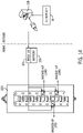
- FIG. 14 illustrates an example circuit for the portable generator and the circuit breaker transfer switch 250 in a third configuration.
- the generator 10 is connectable to a secondary outlet 138.
- the secondary outlet 138 may have a different size or shape than standard outlets.
- the secondary outlet 138 is coupled to the same indoor circuit that the inverter module 101 is connected to within the home or building. Therefore, the generator 10 may charge the battery 130 even when the inverter module 101 is mounted to the wall.
- the generator 10 and inverter module 101 may operate in the hybrid mode of operation, such that the circuit is provided with the sum of the output of the battery 130 and the generator, even with the generator located outside of the home or building and the inverter module located within the home or building.
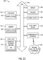
- FIG. 15 illustrates an example controller 400 for the portable generator system.
- the controller 400 may include a processor 300, a memory 352, and a communication interface 353 for interfacing with devices or to the internet and/or other networks 346. In addition to the communication interface 353.
- the components of the control system 400 may communicate using bus 348.
- control system 400 may include an input device 355 and/or a sensing circuit.
- the input device 355 may include the circuit breaker transfer switch 250, a touchscreen coupled to or integrated with the circuit breaker transfer switch 250, a keyboard, a microphone for voice inputs, a camera for gesture inputs, and/or another mechanism.
- control system 400 may include a drive unit 340 for receiving and reading non-transitory computer media 341 having instructions 342. Additional, different, or fewer components may be included.
- the processor 300 is configured to perform instructions 342 stored in memory 352 for executing the algorithms described herein.
- a display 350 may couple with the circuit breaker transfer switch 250.
- the display 350 may be implemented via a mobile device such as a tablet or smartphone.
- the display 350 may be combined with the user input device 355.
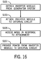
- FIG. 16 illustrates a flow chart for the control system 400 for the operation of the portable generator system.
- the acts of the flow chart may be performed by any combination of the control system 400, the network device or the server. Portions of one or more acts may be performed by the appliance. Additional, different of fewer acts may be included.
- the portable inverter module 101 is detached from the engine/generator.
- the engine/generator may be a portable generator (e.g., on wheels).
- the portable inverter module 101 may include an electrical connection to the engine/generator that provides electrical power from the engine/generator to the portable inverter module 101.
- the portable inverter module 101 may include a first mechanical coupler that physically connects the portable inverter module 101 to the engine/generator.
- the first mechanical coupler may align the portable inverter module 101 may align the portable inverter module 101 and the engine/generator at a predetermined position so that the electrical connection is made.
- a latch, lever, or button may be depressed in order to decouple the first mechanical coupler.
- the portable inverter module 101 is attached to the wall mount and/or the external circuit via a second mechanical coupler.
- the portable inverter module 101 may be moved by the user (e.g., carried, lifted, etc.) from a first location of the engine/generator to a second location of the wall mount and/or external circuit.
- the engine/generator is outdoors and the wall mount and/or external circuit is indoors.
- the controller 400 accesses a predetermined mode in response to the attachment of the inverter module to the wall mount and/or the external circuit.
- the predetermined mode may be a battery mode where one or more loads on the external circuit are provided power from the battery of the inverter module.
- power is provided to the external circuit from the battery.
- Processor 300 may be a general purpose or specific purpose processor, an application specific integrated circuit (ASIC), one or more programmable logic controllers (PLCs), one or more field programmable gate arrays (FPGAs), a group of processing components, or other suitable processing components.
- Processor 300 is configured to execute computer code or instructions stored in memory 352 or received from other computer readable media (e.g., embedded flash memory, local hard disk storage, local ROM, network storage, a remote server, etc.).
- the processor 300 may be a single device or combinations of devices, such as associated with a network, distributed processing, or cloud computing.
- Memory 352 may include one or more devices (e.g., memory units, memory devices, storage devices, etc.) for storing data and/or computer code for completing and/or facilitating the various processes described in the present disclosure.
- Memory 352 may include random access memory (RAM), read-only memory (ROM), hard drive storage, temporary storage, non-volatile memory, flash memory, optical memory, or any other suitable memory for storing software objects and/or computer instructions.
- the communication interface 353 may be connected to a network.
- the network may include wired networks (e.g., Ethernet), wireless networks, or combinations thereof.
- the wireless network may be a cellular telephone network, an 802.11, 802.16, 802.20, or WiMax network, a Bluetooth pairing of devices, or a Bluetooth mesh network.
- the network may be a public network, such as the Internet, a private network, such as an intranet, or combinations thereof, and may utilize a variety of networking protocols now available or later developed including, but not limited to TCP/IP based networking protocols.
- While the computer-readable medium (e.g., memory 352) is shown to be a single medium, the term “computer-readable medium” includes a single medium or multiple media, such as a centralized or distributed database, and/or associated caches and servers that store one or more sets of instructions.
- the term “computer-readable medium” shall also include any medium that is capable of storing, encoding or carrying a set of instructions for execution by a processor or that cause a computer system to perform any one or more of the methods or operations disclosed herein.
- the computer-readable medium can include a solid-state memory such as a memory card or other package that houses one or more non-volatile read-only memories. Further, the computer-readable medium can be a random access memory or other volatile re-writable memory. Additionally, the computer-readable medium can include a magneto-optical or optical medium, such as a disk or tapes or other storage device to capture carrier wave signals such as a signal communicated over a transmission medium. A digital file attachment to an e-mail or other self-contained information archive or set of archives may be considered a distribution medium that is a tangible storage medium.
- the disclosure is considered to include any one or more of a computer-readable medium or a distribution medium and other equivalents and successor media, in which data or instructions may be stored.
- the computer-readable medium may be non-transitory, which includes all tangible computer-readable media.
Landscapes
- Engineering & Computer Science (AREA)
- Power Engineering (AREA)
- Chemical & Material Sciences (AREA)
- Combustion & Propulsion (AREA)
- Mechanical Engineering (AREA)
- General Engineering & Computer Science (AREA)
- Charge And Discharge Circuits For Batteries Or The Like (AREA)
- Control Of Eletrric Generators (AREA)
Abstract
Description
- This application claims priority benefit of Provisional Application No.
63/192,424 (Docket No. 010222-21004A) filed May 24, 2021 - The present application relates generally to a hybrid generator with a detachable power unit and integration into a wall panel.
- An engine-generator set, which may be referred to as a generator or a genset, may include an engine and an alternator or another device for generating electrical energy or power. One or more generators may provide electrical power to a load through a power bus. The power bus, which may be referred to as a generator bus or common bus, transfers the electrical power from the engine-generator set to a load. In many examples, the electrical load on the engine-generator set may vary over time and challenges remain in providing an efficient generator that can adapt to varying loads.
- Exemplary embodiments are described herein with reference to the following drawings, according to an exemplary embodiment.
-
FIG. 1 illustrates an example portable generator. -
FIG. 2 illustrates an example portable generator having at least two separable generator modules. -
FIG. 3 illustrates an output module for the example portable generator. -
FIG. 4 illustrates a circuit to represent a hybrid mode of operation. -
FIG. 5 illustrates a circuit to represent a remote mode of operation. -
FIG. 6 illustrates an example wall mount for the output module. -
FIG. 7 illustrates an example home layout for the portable generator. -
FIG. 8 illlustrates an example transfer switch for the example home layout for the portable generator. -
FIG. 9 illustrates an example circuit breaker transfer switch. -
FIG. 10 illustrates example positions and indicators for the circuit breaker transfer switch. -
FIG. 11 illustrates example connections for the circuit breaker transfer switch. -
FIG. 12 illustrates an example circuit for the portable generator and the circuit breaker transfer switch in a first configuration. -
FIG. 13 illustrates an example circuit for the portable generator and the circuit breaker transfer switch in a second configuration. -
FIG. 14 illustrates an example circuit for the portable generator and the circuit breaker transfer switch in a third configuration. -
FIG. 15 illustrates a controller for the portable generator. -
FIG. 16 illustrates a flow chart for the controller ofFIG. 15 . - The following embodiments include an engine-generator set, which may be referred to as a generator or a genset, and may include an engine and an alternator. The alternator of the genset is an example electric machine. The alternator may include permanent magnets for the exciter of the generator or the main generator or the exciter. The generator may include a wound rotor generator with a permanent magnet exciter, the electrical machine may also act as a motor as well. Other embodiments of electrical machines include permanent magnet brush-type direct current (DC) machines, permanent magnet brushless DC machines, series-wound or universal machines, induction alternating current (AC) machines, synchronous AC machines, synchronous reluctance machines, switched reluctance machines, among others. Any machine may be used as a motor, selectively between a motor and a generator, or entirely as a generator.
- It should be noted that while engine is used as a term to describe the prime mover converting fuel to a rotational speed and torque applied to a generator, any apparatus capable of providing mechanical torque and rotation or of requiring mechanical torque and rotation may be coupled to an electrical machine, operating as a motor or a generator. An electrical machine may also provide torque without causing rotation, such as to hold a position against a load. Thus, rotation is not required to define a device as an electrical machine. Further, the engine maybe be configured for a constant speed or a variable speed that varies based on the load. Likewise, the alternator may be included in a variable speed generator.
-
FIG. 1 illustrates an exampleportable generator 10. The generator may be considered portable in that it is movable between various geographic locations. The generator may be transported via a truck or trailer. The generator may include ahandle 104 and/orwheels 106. The user may move the generator by grasping thehandle 104 and pulling or pushing the generator along a surface on the wheels. - The
generator 10 may comprise modular components (e.g., generator modules) that are attachable and removable from each other. Thegenerator 10 may include a first generator module (e.g., engine module 102) and a second generator module (e.g., inverter module 101). Theengine module 102 may include the engine and one or more additional components such as a fuel system, an exhaust system, a starter system, a coolant system or others. Theinverter module 101 may include at least an alternator and may also include a battery or other storage device, an output system, and one or more coupling mechanisms. Additional, different, or fewer components may be included. -
FIG. 2 illustrates an example portable generator having at least two separable generator modules includinginverter module 101 and theengine module 102. - The
inverter module 101 may include acontroller 100, aninverter circuit 110, acharging circuit 120, and at least onebattery 130. Theinverter module 101 may also include a coupling device including one or both of amechanical coupling device 105 and anelectrical coupling device 115. Theinverter module 101 may include an enclosure or housing that supported and encloses thebattery 130, the charging circuit, and the electric power outlet. The enclosure is detachable from thegenerator 10 as described herein. Additional, different, or fewer components may be included. - The output of the
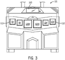
inverter module 101 may include anoutlet 150. As shown inFIG. 3 , the output of for the exampleportable generator 10 may include multiple types of outlets (e.g.,first outlets 111,second outlets 112, and third outlets 113). The outlets may have different shapes and sizes. The outlets may have different voltage ratings, current ratings, or other electrical parameters. - The
inverter circuit 110 may be configured to convert electrical power stored in thebattery 130 to an alternating current signal for the electric power outlet. Theinverter circuit 110 is configured to change direct current (e.g., from the energy stored in the battery 130) to alternating current for the output. The output may be a square wave, modified sine wave, pulsed sine wave, pulse width modulated wave or sine wave depending on circuit design. - The
inverter circuit 110 may include an H-bridge having multiple transistor switches and one or more antiparallel diodes. The H-bridge may include four transistors or four transistor-diode pairs. - The
inverter module 101 may include a charging circuit coupled to an output of a generator and configured to charge thebattery 130. The charging circuit may include an AC to DC converter. The charging circuit may include one or more diodes. The charging circuit may include a rectifier circuit, which may include four diodes and a smoothing capacitor. - The
generator 10 may include amechanical coupling device 105. One side (e.g., connector 116) of themechanical coupling device 105 is on theinverter module 101 and the other side (e.g., connector 206) of themechanical coupling device 105 is on theengine module 102. In addition, the wall mount may include amechanical coupling device 105 configured to mate with another portion (e.g., connector 117) of themechanical coupling device 105 of theinverter module 101. - The
mechanical coupling device 105 may include a snap fit connection such as a tab and receiving hole. The tab is inserted into the receiving hole to secure theinverter module 101 to theengine module 102. A release mechanism (e.g., release button) may be depressed to remove the tab from the receiving hole and detach theinverter module 101 from theengine module 102. Themechanical coupling device 105 may include a first latch configured to secure the enclosure to the generator and a second latch configured to secure the enclosure to a mount. Other connections may include bolt and clevis pin, buckles, or other examples. - The
mechanical coupling device 105 may align theinverter module 101 to theengine module 102 to attach and detach the generator and engine modules from each other in a first configuration. Themechanical coupling device 105 may align theinverter module 101 to the wall mount to attach and detach theinverter module 101 to an external circuit in a second configuration. - For example, different electrical connections may be made to the
inverter module 101 depending on whether theinverter module 101 is in the first configuration or the second configuration. Thegenerator 10 may include anelectrical coupling device 115 including agenerator output 108 on theengine module 102 side. On theinverter module 101 side, a firstelectrical contact 208 configured to connect the charging circuit to the alternator or the generator output 108 (e.g., via the charging circuit 120) and a secondelectrical contact 119 configured to connect thebattery 130 to the external circuit. - The
inverter module 101 may include an electric power outlet configured to provide an output from thebattery 130, the generator, or a combination of thebattery 130 and the generator. Thecontroller 100 is configured to select a mode for the generator module. Example modes include a quiet mode, a maximum power mode, a no generator mode, and/or a hybrid mode. Thecontroller 100 may select and cause thegenerator 10 to operate on a specific cycle. - In the quiet mode, the
controller 100 may instruct the generator 10 (e.g., engine) only when the battery power has been depleted. Once, the battery power is no longer available, or below a predetermined threshold, thecontroller 100 instructs thegenerator 10 to resume operation. Thus, when possible, the generator 10 (e.g., engine) is not operated, which reduces noise when possible. - In the maximum power mode, the
controller 100 may instruct the generator 10 (e.g., engine) to operate at all times, or any time there is a load on the generator. - In the no generator mode, the
controller 100 may instruct the generator 10 (e.g., engine) to not operate. The engine may be turned off regardless of load and/or regardless of battery capacity. -
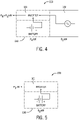
FIG. 4 illustrates a circuit 180 to represent a hybrid mode of operation. In the hybrid mode, thecontroller 100 may instruct the engine to operate when the load is above a predetermined level (e.g., during a predetermined load condition). The predetermined level may be greater than both the rated output of thegenerator 10 and the output of thebattery 130. However, the predetermined level may be equal or less than the sum of the rated power of thegenerator 10 and the output of thebattery 130.FIG. 4 illustrates circuit 180 to represent a hybrid mode of operation in which the output of theinverter module 101 includes the sum of the output of thegenerator 10 and the output of thebattery 130. -
FIG. 5 illustrates acircuit 190 to represent a remote mode of operation. In a wall mount mode (e.g., remote mode) of operation, thecontroller 100 may instruct the generator 10 (e.g., engine) to not operate. The wall mount mode corresponds to when theinverter module 101 is connected to the wall, and not coupled to theengine module 102. The engine may be turned off regardless of load and/or regardless of battery capacity. Any available power is provided to the attached circuit from thebattery 130.FIG. 5 illustratescircuit 190 to represent a remote mode of operation and illustrates that the output of thebattery 130 is the same as the output of theinverter module 101. - In one example, the mode is determined by the
controller 100 in response to sensor data. For example, a sensing circuit may generate sensor data indicative of the load on the generator. The load may be detected by measured electrical parameters at the output of the alternator. Example, electrical characteristics include power, current, and voltage. The load may be detected by measured electrical parameters at the field windings of the alternator. The amount of flux induced on the field coil by a current in the armature windings may be indicative of an output of the generator. Further, because a load on the generator impacts the current in the armature windings, the sensor data may be indicative of the load on the generator. The sensor data may be temperature data, which may indicate the resistance of the field coils or armature windings. The sensor data may be magnetic data measured on damper windings of the rotor, parallel or perpendicular to the primary rotor flux. The sensor data may describe a physical position of the rotor in any direction or a capacitance that is related to proximity to a surface, the sensor data may be acceleration data or strain data measured on the rotor, or the sensor data may be a deflection measurement on any axis or mode. - In one example, the mode is determined by the
controller 100 in response to a user selection. That is, the user may provide input directly to the generator. One example is auser input device 160. Theuser input device 160 may include a display, a touchscreen, a keypad, a button, or other device for providing the user selection to thecontroller 100. Theuser input device 160 may include one or more indicators such as a batter level indicator configured to display the battery level or stored power in theinverter module 101. - In one example, the mode is determined by the
controller 100 in response to a time or day (e.g., calendar). Certain modes may be assigned to certain times of days, days of the week, or days of the year. For example, the quiet mode may be assigned to overnight hours such as 10 P.M. to 6 A.M. -
FIG. 6 illustrates a wall mount for the output module. The wall mount includes aconnector 107 for themechanical coupling device 105 and anelectrical connector 109 for theelectrical coupling device 115. Theconnector 107 attaches theinverter module 101 to the wall mount and theelectrical connector 109 provides an electrical path from the output of theinverter module 101 to anelectrical panel 220 including one ormore circuit breakers 221. - In some examples, as shown by
FIGS. 7 and8 theinverter module 101 is connected to theelectrical panel 220 and/or the home or building circuits via atransfer switch 230.FIG. 7 illustrates an example home layout for theportable generator 10.FIG. 8 illlustrates anexample transfer switch 230 for the example home layout for the portable generator. Thetransfer switch 230 may include a detection circuit configured to detect that theinverter module 101 has been connected to thetransfer switch 230 and/or that the utility has been disconnected or lost service. In response to the detection, thetransfer switch 230 may switch power from being supplied by thehome breaker circuit 220 to theinvertor module 101 for a predetermined set of circuits. The predetermined set of circuits may include essential circuits (e.g., refrigeration, lights, medical equipment, etc.). Thetransfer switch 230 may include Silicon-controlled rectifiers (SCRs) to transfer the load of the predetermined set of circuits. - In some examples, as shown by
FIGS. 9-11 , theinvertor module 101 is connected directed to theelectrical panel 220 using a generator circuit breaker with integrated transfer switch. -
FIG. 9 illustrates an example circuitbreaker transfer switch 250. The circuitbreaker transfer switch 250 includes aselectable switch 251 and a current limitingswitch 252. The current limitingswitch 252 is connected to the grid circuit and the load circuit. - The circuit
breaker transfer switch 250 includes afirst connection point 261, asecond connection point 262, and athird connection point 263. Thefirst connection point 261 is electrically connected to a grid circuit. Thesecond connection point 262 is electrically connected to a load circuit. Thethird connection point 263 is electrically connected to a generator circuit. -
FIG. 10 illustrates example positions and indicators for the circuitbreaker transfer switch 250.FIG. 11 illustrates example connections for the circuitbreaker transfer switch 250 in a side view of the circuitbreaker transfer switch 250. - The
selectable switch 251 is connected to the load circuit and the generator circuit. Theselectable switch 251 is configured for three positions including a first position in which the current limitingswitch 252 is closed and theselectable switch 251 is open, a second position in which the current limitingswitch 252 is open and theselectable switch 251 is closed, and a third position in which the current limitingswitch 252 is open and theselectable switch 251 is open. The first position corresponds to utility operation, labeled "Grid" inFIG. 10 . The second position corresponds to generator operation, labeled "Gen" inFIG. 10 . The third position corresponds to an over current condition, labeled "Tripped" inFIG. 10 , in the home or building circuit. - The circuit
breaker transfer switch 250 includes at least one indicator including a first status for the current limitingswitch 252 and a second status for theselectable switch 251. - The circuit
breaker transfer switch 250 includes a connection outlet electrically connected to the third connection point and configured to receive a generator module, as described herein. -
FIGS. 12-14 illustrate the portable generator in various configurations that correspond to various modes of operation. -
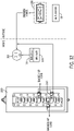
FIG. 12 illustrates an example circuit for the portable generator and the circuitbreaker transfer switch 250 in a first configuration. In the first configuration, theinverter module 101 is connected to anindoor circuit outlet 118 for the circuit within the home or building. The circuit may have a corresponding circuitbreaker transfer switch 250 within thepanel 220. The inverter module provides backup power to theindoor circuit outlet 118 and corresponding circuit, which may occur when thegenerator 10 is disconnected. -
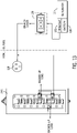
FIG. 13 illustrates an example circuit for the portable generator and the circuit breaker transfer switch in a second configuration. In the second configuration, theinverter module 101 is connected to thegenerator 10. Theinverter module 101 may be connected tooutdoor circuit outlet 128, which is connected to the same circuit within the home or the building as theindoor circuit outlet 118. The inverter module provides backup power to theoutdoor circuit outlet 128 and corresponding circuit. -
FIG. 14 illustrates an example circuit for the portable generator and the circuitbreaker transfer switch 250 in a third configuration. In the third configuration, thegenerator 10 is connectable to asecondary outlet 138. Thesecondary outlet 138 may have a different size or shape than standard outlets. Thesecondary outlet 138 is coupled to the same indoor circuit that theinverter module 101 is connected to within the home or building. Therefore, thegenerator 10 may charge thebattery 130 even when theinverter module 101 is mounted to the wall. In addition, thegenerator 10 andinverter module 101 may operate in the hybrid mode of operation, such that the circuit is provided with the sum of the output of thebattery 130 and the generator, even with the generator located outside of the home or building and the inverter module located within the home or building. -
FIG. 15 illustrates anexample controller 400 for the portable generator system. Thecontroller 400 may include aprocessor 300, amemory 352, and acommunication interface 353 for interfacing with devices or to the internet and/orother networks 346. In addition to thecommunication interface 353. The components of thecontrol system 400 may communicate usingbus 348. - Optionally, the
control system 400 may include aninput device 355 and/or a sensing circuit. Theinput device 355 may include the circuitbreaker transfer switch 250, a touchscreen coupled to or integrated with the circuitbreaker transfer switch 250, a keyboard, a microphone for voice inputs, a camera for gesture inputs, and/or another mechanism. - Optionally, the
control system 400 may include adrive unit 340 for receiving and readingnon-transitory computer media 341 havinginstructions 342. Additional, different, or fewer components may be included. Theprocessor 300 is configured to performinstructions 342 stored inmemory 352 for executing the algorithms described herein. Adisplay 350 may couple with the circuitbreaker transfer switch 250. Thedisplay 350 may be implemented via a mobile device such as a tablet or smartphone. Thedisplay 350 may be combined with theuser input device 355. -
FIG. 16 illustrates a flow chart for thecontrol system 400 for the operation of the portable generator system. The acts of the flow chart may be performed by any combination of thecontrol system 400, the network device or the server. Portions of one or more acts may be performed by the appliance. Additional, different of fewer acts may be included. - At act S101, the
portable inverter module 101 is detached from the engine/generator. The engine/generator may be a portable generator (e.g., on wheels). Theportable inverter module 101 may include an electrical connection to the engine/generator that provides electrical power from the engine/generator to theportable inverter module 101. Theportable inverter module 101 may include a first mechanical coupler that physically connects theportable inverter module 101 to the engine/generator. The first mechanical coupler may align theportable inverter module 101 may align theportable inverter module 101 and the engine/generator at a predetermined position so that the electrical connection is made. In order to detach theportable inverter module 101, a latch, lever, or button may be depressed in order to decouple the first mechanical coupler. - At act S103, the
portable inverter module 101 is attached to the wall mount and/or the external circuit via a second mechanical coupler. Theportable inverter module 101 may be moved by the user (e.g., carried, lifted, etc.) from a first location of the engine/generator to a second location of the wall mount and/or external circuit. In some examples, the engine/generator is outdoors and the wall mount and/or external circuit is indoors. - At act S105, the controller 400 (e.g., through processor 300) accesses a predetermined mode in response to the attachment of the inverter module to the wall mount and/or the external circuit. The predetermined mode may be a battery mode where one or more loads on the external circuit are provided power from the battery of the inverter module. At act S107, power is provided to the external circuit from the battery.
-
Processor 300 may be a general purpose or specific purpose processor, an application specific integrated circuit (ASIC), one or more programmable logic controllers (PLCs), one or more field programmable gate arrays (FPGAs), a group of processing components, or other suitable processing components.Processor 300 is configured to execute computer code or instructions stored inmemory 352 or received from other computer readable media (e.g., embedded flash memory, local hard disk storage, local ROM, network storage, a remote server, etc.). Theprocessor 300 may be a single device or combinations of devices, such as associated with a network, distributed processing, or cloud computing. -
Memory 352 may include one or more devices (e.g., memory units, memory devices, storage devices, etc.) for storing data and/or computer code for completing and/or facilitating the various processes described in the present disclosure.Memory 352 may include random access memory (RAM), read-only memory (ROM), hard drive storage, temporary storage, non-volatile memory, flash memory, optical memory, or any other suitable memory for storing software objects and/or computer instructions. - The
communication interface 353 may be connected to a network. The network may include wired networks (e.g., Ethernet), wireless networks, or combinations thereof. The wireless network may be a cellular telephone network, an 802.11, 802.16, 802.20, or WiMax network, a Bluetooth pairing of devices, or a Bluetooth mesh network. Further, the network may be a public network, such as the Internet, a private network, such as an intranet, or combinations thereof, and may utilize a variety of networking protocols now available or later developed including, but not limited to TCP/IP based networking protocols. - While the computer-readable medium (e.g., memory 352) is shown to be a single medium, the term "computer-readable medium" includes a single medium or multiple media, such as a centralized or distributed database, and/or associated caches and servers that store one or more sets of instructions. The term "computer-readable medium" shall also include any medium that is capable of storing, encoding or carrying a set of instructions for execution by a processor or that cause a computer system to perform any one or more of the methods or operations disclosed herein.
- In a particular non-limiting, exemplary embodiment, the computer-readable medium can include a solid-state memory such as a memory card or other package that houses one or more non-volatile read-only memories. Further, the computer-readable medium can be a random access memory or other volatile re-writable memory. Additionally, the computer-readable medium can include a magneto-optical or optical medium, such as a disk or tapes or other storage device to capture carrier wave signals such as a signal communicated over a transmission medium. A digital file attachment to an e-mail or other self-contained information archive or set of archives may be considered a distribution medium that is a tangible storage medium. Accordingly, the disclosure is considered to include any one or more of a computer-readable medium or a distribution medium and other equivalents and successor media, in which data or instructions may be stored. The computer-readable medium may be non-transitory, which includes all tangible computer-readable media.
Claims (20)
- A generator module comprising:a battery;a charging circuit coupled to an output of a generator and configured to charge the battery;an electric power outlet configured to provide an output from the battery, the generator, or a combination of the battery and the generator; andan enclosure including the battery, the charging circuit, and the electric power outlet, the enclosure detachable from the generator.
- The generator module of claim 1, further comprising:
a coupling device configured to (i) attach and detach the generator module to the generator in a first configuration, and (ii) attach and detach the generator module to an external circuit in a second configuration. - The generator module of claim 2, wherein the coupling device includes a first latch configured to secure the enclosure to the generator and a second latch configured to secure the enclosure to a mount.
- The generator module of claim 3, wherein the mount is a wall mount.
- The generator module of claim 2, wherein the coupling device includes a first electrical contact configured to connect the generator to the battery and a second electrical contact configured to connect the battery to the external circuit.
- The generator module of claim 1, further comprising:
an inverter configured to convert electrical power stored in the battery to an alternating current signal for the electric power outlet. - The generator module of claim 6, further comprising:
a controller configured to select a mode for the generator module. - The generator module of claim 7, wherein the mode includes a quiet mode in which operation of the generator is minimized.
- The generator module of claim 7, wherein the mode includes a maximum power mode in which the battery and the generator provide power to the electric power outlet.
- The generator module of claim 7, wherein the mode includes a no-generator mode in which operation of the generator is prevented.
- The generator module of claim 7, wherein the mode includes a hybrid mode in which the generated is operated during a predetermined load condition.
- The generator module of claim 7, further comprising:
a sensing circuit configured to detect a load on the generator. - The generator module of claim 7, further comprising:
a battery level indicator in communication with the controller. - A method comprising:detaching an inverter module including a battery from a portable generator;attaching the inverter module to an external circuit;determining a predetermined mode of operation in response to the attachment of the inverter module to the external circuit; andproviding power to the external circuit from the battery.
- A generator circuit breaker for a wall panel, the generator circuit breaker comprising:a first connection point electrically connected to a grid circuit;a second connection point electrically connected to a load circuit;a third connection point electrically connected to a generator circuit;a current limiting switch connected to the grid circuit and the load circuit; anda selectable switch connected to the load circuit and the generator circuit, wherein the selectable switch is configured for three positions including:(i) a first position in which the current limiting switch is closed and the selectable switch is open;(ii) a second position in which the current limiting switch is open and the selectable switch is closed; and(iii) a third position in which the current limiting switch is open and the selectable switch is open.
- The generator circuit breaker of claim 15, wherein the first position corresponds to utility operation.
- The generator circuit breaker of claim 15, wherein the second position corresponds to generator operation.
- The generator circuit breaker of claim 15, wherein the third position corresponds to a trip.
- The generator circuit breaker of claim 15, further comprising:at least one indicator including a first status for the current limiting switch and a second status for the selectable switch.
- The generator circuit breaker of claim 15, further comprising:
a connection outlet electrically connected to the third connection point and configured to receive a generator module, the generator module comprising:a battery;a charging circuit coupled to an output of a generator and configured to charge the battery;an electric power outlet configured to provide an output from the battery, the generator, or a combination of the battery and the generator; andan enclosure including the battery, the charging circuit, and the electric power outlet, the enclosure detachable from the generator.
Applications Claiming Priority (2)
| Application Number | Priority Date | Filing Date | Title |
|---|---|---|---|
| US202163192424P | 2021-05-24 | 2021-05-24 | |
| US17/741,893 US12592573B2 (en) | 2021-05-24 | 2022-05-11 | Hybrid generator with detachable power unit and panel integration |
Publications (3)
| Publication Number | Publication Date |
|---|---|
| EP4105459A2 true EP4105459A2 (en) | 2022-12-21 |
| EP4105459A3 EP4105459A3 (en) | 2023-03-01 |
| EP4105459B1 EP4105459B1 (en) | 2024-12-18 |
Family
ID=81748598
Family Applications (1)
| Application Number | Title | Priority Date | Filing Date |
|---|---|---|---|
| EP22173751.3A Active EP4105459B1 (en) | 2021-05-24 | 2022-05-17 | Hybrid generator with detachable power unit and panel integration, method |
Country Status (3)
| Country | Link |
|---|---|
| US (1) | US12592573B2 (en) |
| EP (1) | EP4105459B1 (en) |
| CN (1) | CN115395595A (en) |
Cited By (1)
| Publication number | Priority date | Publication date | Assignee | Title |
|---|---|---|---|---|
| US20230062873A1 (en) * | 2021-08-27 | 2023-03-02 | Anthony Vito Dipaola | Apparatus for electric car booster and charger over fast charging DC |
Families Citing this family (2)
| Publication number | Priority date | Publication date | Assignee | Title |
|---|---|---|---|---|
| US20240186926A1 (en) * | 2022-12-06 | 2024-06-06 | Moise Michel | Generator Transformer |
| US12463259B1 (en) | 2025-01-10 | 2025-11-04 | Enginuity Power Systems, Inc. | Integrated and compact combined heat and power systems and related methods |
Family Cites Families (38)
| Publication number | Priority date | Publication date | Assignee | Title |
|---|---|---|---|---|
| DE3766385D1 (en) | 1986-02-10 | 1991-01-10 | Merlin Gerin | MECHANISM TO SNAP AND DISCONNECT AN ELECTRICAL SWITCH WITH MAIN AND AUXILIARY CIRCUITS. |
| FR2771560B1 (en) | 1997-11-24 | 2000-01-28 | Gec Alsthom T & D Sa | SWITCHING DEVICE FOR A POWER PLANT GENERATOR AND A TRANSFORMER WITH A THREE-POSITION DISCONNECTOR CONNECTED TO THE TRANSFORMER |
| FR2771561B1 (en) | 1997-11-24 | 2000-01-28 | Gec Alsthom T & D Sa | SWITCHING DEVICE FOR A POWER PLANT GENERATOR AND A TRANSFORMER WITH A THREE-POSITION DISCONNECTOR |
| GB9821434D0 (en) | 1998-10-03 | 1998-11-25 | Grant Duncan | A battery management system |
| US6531790B2 (en) | 2000-08-01 | 2003-03-11 | Advanced Controls, Inc. | Generator transfer switching system with multiple generator modes |
| WO2002065620A1 (en) | 2001-02-13 | 2002-08-22 | Yanmar Co.,Ltd. | Electric power system with engine-driven generator |
| US6791211B1 (en) | 2001-08-24 | 2004-09-14 | Reliance Controls Corporation | Double pole circuit breaker and switch system for a transfer switch |
| US8319357B2 (en) * | 2002-06-06 | 2012-11-27 | Black & Decker Inc. | Starter system for portable internal combustion engine electric generators using a portable universal battery pack |
| US8820286B2 (en) | 2003-08-28 | 2014-09-02 | Mainstream Engineering Corporation | Lightweight portable electric generator with integrated starter/alternator |
| JP4303152B2 (en) | 2004-03-22 | 2009-07-29 | 株式会社日立製作所 | Power generation system and control method thereof |
| US7142950B2 (en) | 2004-05-28 | 2006-11-28 | American Power Conversion Corporation | Methods and apparatus for providing and distributing standby power |
| US7248490B2 (en) | 2004-06-17 | 2007-07-24 | Gaia Power Technologies, Inc. | Battery and inverter configuration with increased efficiency |
| US7126068B2 (en) | 2004-12-22 | 2006-10-24 | Square D Company | Switching mechanism with mechanical interlocking and manual override |
| FR2896336B1 (en) | 2006-01-17 | 2009-04-03 | Areva T & D Sa | CIRCUIT BREAKER ALTERNATOR OF COMPACT STRUCTURE |
| US7388299B2 (en) | 2006-06-21 | 2008-06-17 | Tracy Blackman | Retrofittable power distribution system for a household |
| KR100748311B1 (en) | 2006-09-01 | 2007-08-09 | 삼성에스디아이 주식회사 | Battery packs and power input devices |
| GB2442345B (en) | 2006-09-29 | 2011-07-06 | Milwaukee Electric Tool Corp | Power-generating apparatus, such as a generator |
| US8994336B2 (en) | 2007-02-26 | 2015-03-31 | Black & Decker Inc. | Portable alternating current inverter having reduced impedance losses |
| CN201570457U (en) | 2009-08-14 | 2010-09-01 | 厦门威尔圣电气实业有限公司 | Novel drawer breaker structure |
| US8514551B2 (en) | 2010-06-17 | 2013-08-20 | Diversified Control, Inc. | Panelboard enclosure with external power cutoff switch |
| CN102624312B (en) | 2011-01-27 | 2018-11-02 | 创科户外产品技术有限公司 | Mixed conversion generator |
| JP5383745B2 (en) | 2011-05-31 | 2014-01-08 | 三菱重工業株式会社 | Power supply |
| CN202260612U (en) | 2011-09-30 | 2012-05-30 | 首瑞(北京)投资管理集团有限公司 | AC power supply system used in transformer station |
| ITTO20130599A1 (en) | 2013-07-16 | 2015-01-17 | Avio Spa | MODULAR ELECTRIC POWER CONVERSION SYSTEM FOR A REVERSIBLE ELECTROMAGNETIC DEVICE |
| US9419473B2 (en) | 2013-12-19 | 2016-08-16 | Eaton Corporation | Automatic transfer switch (ATS) bypass switch |
| US9692254B2 (en) | 2014-01-28 | 2017-06-27 | Eaton Corporation | Three-source automatic redundant bypass-isolation switches and related systems and methods |
| US20160359362A1 (en) | 2015-06-05 | 2016-12-08 | Liebert Corporation | Fast Restart Of Flywheel In Uninterruptible Power Supply System Having Flywheel System/Battery Combination |
| US10931139B1 (en) | 2015-12-29 | 2021-02-23 | Signify Holding B.V. | Emergency battery packs for low voltage systems |
| US9929571B1 (en) | 2016-03-29 | 2018-03-27 | Elite Power Solutions Llc | Integrated energy storage system |
| US9779891B1 (en) | 2016-04-04 | 2017-10-03 | Eaton Corporation | Breaker motorized secondary connector - field installable kit |
| US9905388B2 (en) | 2016-06-27 | 2018-02-27 | Elmer Edmonds | Double-throw switch for breaker box |
| WO2018067435A1 (en) | 2016-10-04 | 2018-04-12 | Black & Decker Inc. | Battery pack charger system |
| CA2959731A1 (en) | 2017-03-02 | 2018-09-02 | Louis A. Piccone | A personal electric generator providing substantial independence from the grid |
| CN207368867U (en) | 2017-05-08 | 2018-05-15 | 创科(澳门离岸商业服务)有限公司 | Portable Power Supplies, Portable DC Power Supplies & Kits |
| GB2560056B (en) | 2017-05-10 | 2019-04-10 | 618 Safesource Ltd | Power Source for use in meter installation |
| US11394236B2 (en) | 2017-10-02 | 2022-07-19 | Enatel | Modular power systems |
| US20220052411A1 (en) | 2018-11-28 | 2022-02-17 | Cadenza Innovation, Inc. | Modular Battery System |
| US11207986B2 (en) * | 2019-02-12 | 2021-12-28 | Ford Global Technologies, Llc | Scaled home energy storage systems and associated uses |
-
2022
- 2022-05-11 US US17/741,893 patent/US12592573B2/en active Active
- 2022-05-17 EP EP22173751.3A patent/EP4105459B1/en active Active
- 2022-05-23 CN CN202210564767.1A patent/CN115395595A/en active Pending
Cited By (1)
| Publication number | Priority date | Publication date | Assignee | Title |
|---|---|---|---|---|
| US20230062873A1 (en) * | 2021-08-27 | 2023-03-02 | Anthony Vito Dipaola | Apparatus for electric car booster and charger over fast charging DC |
Also Published As
| Publication number | Publication date |
|---|---|
| US20220376526A1 (en) | 2022-11-24 |
| EP4105459B1 (en) | 2024-12-18 |
| CN115395595A (en) | 2022-11-25 |
| US12592573B2 (en) | 2026-03-31 |
| EP4105459A3 (en) | 2023-03-01 |
Similar Documents
| Publication | Publication Date | Title |
|---|---|---|
| EP4105459A2 (en) | Hybrid generator with detachable power unit and panel integration | |
| US11621662B2 (en) | Battery and motor system for replacing internal combustion engine | |
| US20230238910A1 (en) | Battery and motor system for replacing internal combustion engine | |
| US11072253B2 (en) | Power circuit for power supply in an electrically driven vehicle and stationary energy supply system | |
| US10763690B2 (en) | Vehicle-side charging circuit for a vehicle with electric drive, and method for operating a vehicle-side current converter, and use of at least one winding of a vehicle-side electric machine for intermediate storagectrical machine for buffer | |
| US12289012B2 (en) | Generator and battery backup with conversion device | |
| US10875418B2 (en) | Charge control apparatus and system | |
| JP5733420B2 (en) | Mobile power supply device | |
| JP2013527736A (en) | Vehicle bi-directional power inverter system and method | |
| US10784802B2 (en) | Generator starter of a turbomachine with asynchronous multi-winding electric machine | |
| CN104993580B (en) | Oil electricity mixed DC electric supply installation | |
| WO2013111127A1 (en) | Charge spot device for charging electric vehicles | |
| WO2013107003A1 (en) | Transfer switch | |
| JP6024573B2 (en) | Power connector and power supply system | |
| WO2011055230A3 (en) | Electric drive and battery-charging power electronic system | |
| US9744868B2 (en) | Electric circuit for charging at least one electrical energy storage unit by means of an electrical network | |
| JP2013051745A (en) | Power conversion system | |
| EP2775592A2 (en) | Alternator for a power generation system | |
| JP2016007118A (en) | Rotary electric machine system | |
| JP2020005394A (en) | Power source system | |
| NL2030568B1 (en) | Electrical device, computing device, vehicle, method and computer program | |
| JP3213784U (en) | Voltage converter | |
| CA3035630A1 (en) | Charging station, electric vehicle and system comprising a charging station and an electric vehicle | |
| JP6239042B1 (en) | Starter for internal combustion engine | |
| CN116780684A (en) | Electronic equipment, power supply equipment, charging methods and storage media |
Legal Events
| Date | Code | Title | Description |
|---|---|---|---|
| PUAI | Public reference made under article 153(3) epc to a published international application that has entered the european phase |
Free format text: ORIGINAL CODE: 0009012 |
|
| STAA | Information on the status of an ep patent application or granted ep patent |
Free format text: STATUS: THE APPLICATION HAS BEEN PUBLISHED |
|
| AK | Designated contracting states |
Kind code of ref document: A2 Designated state(s): AL AT BE BG CH CY CZ DE DK EE ES FI FR GB GR HR HU IE IS IT LI LT LU LV MC MK MT NL NO PL PT RO RS SE SI SK SM TR |
|
| PUAL | Search report despatched |
Free format text: ORIGINAL CODE: 0009013 |
|
| AK | Designated contracting states |
Kind code of ref document: A3 Designated state(s): AL AT BE BG CH CY CZ DE DK EE ES FI FR GB GR HR HU IE IS IT LI LT LU LV MC MK MT NL NO PL PT RO RS SE SI SK SM TR |
|
| RIC1 | Information provided on ipc code assigned before grant |
Ipc: H02J 7/00 20060101ALI20230120BHEP Ipc: F02B 63/04 20060101AFI20230120BHEP |
|
| STAA | Information on the status of an ep patent application or granted ep patent |
Free format text: STATUS: REQUEST FOR EXAMINATION WAS MADE |
|
| 17P | Request for examination filed |
Effective date: 20230606 |
|
| RBV | Designated contracting states (corrected) |
Designated state(s): AL AT BE BG CH CY CZ DE DK EE ES FI FR GB GR HR HU IE IS IT LI LT LU LV MC MK MT NL NO PL PT RO RS SE SI SK SM TR |
|
| GRAP | Despatch of communication of intention to grant a patent |
Free format text: ORIGINAL CODE: EPIDOSNIGR1 |
|
| STAA | Information on the status of an ep patent application or granted ep patent |
Free format text: STATUS: GRANT OF PATENT IS INTENDED |
|
| INTG | Intention to grant announced |
Effective date: 20240718 |
|
| RIN1 | Information on inventor provided before grant (corrected) |
Inventor name: CHIU, HARRISON Inventor name: MAROTZ, BENJAMIN |
|
| GRAS | Grant fee paid |
Free format text: ORIGINAL CODE: EPIDOSNIGR3 |
|
| RAP1 | Party data changed (applicant data changed or rights of an application transferred) |
Owner name: DISCOVERY ENERGY, LLC |
|
| GRAA | (expected) grant |
Free format text: ORIGINAL CODE: 0009210 |
|
| STAA | Information on the status of an ep patent application or granted ep patent |
Free format text: STATUS: THE PATENT HAS BEEN GRANTED |
|
| AK | Designated contracting states |
Kind code of ref document: B1 Designated state(s): AL AT BE BG CH CY CZ DE DK EE ES FI FR GB GR HR HU IE IS IT LI LT LU LV MC MK MT NL NO PL PT RO RS SE SI SK SM TR |
|
| REG | Reference to a national code |
Ref country code: CH Ref legal event code: EP |
|
| REG | Reference to a national code |
Ref country code: DE Ref legal event code: R096 Ref document number: 602022008745 Country of ref document: DE |
|
| REG | Reference to a national code |
Ref country code: IE Ref legal event code: FG4D |
|
| REG | Reference to a national code |
Ref country code: LT Ref legal event code: MG9D |
|
| PG25 | Lapsed in a contracting state [announced via postgrant information from national office to epo] |
Ref country code: HR Free format text: LAPSE BECAUSE OF FAILURE TO SUBMIT A TRANSLATION OF THE DESCRIPTION OR TO PAY THE FEE WITHIN THE PRESCRIBED TIME-LIMIT Effective date: 20241218 |
|
| PG25 | Lapsed in a contracting state [announced via postgrant information from national office to epo] |
Ref country code: FI Free format text: LAPSE BECAUSE OF FAILURE TO SUBMIT A TRANSLATION OF THE DESCRIPTION OR TO PAY THE FEE WITHIN THE PRESCRIBED TIME-LIMIT Effective date: 20241218 |
|
| PG25 | Lapsed in a contracting state [announced via postgrant information from national office to epo] |
Ref country code: BG Free format text: LAPSE BECAUSE OF FAILURE TO SUBMIT A TRANSLATION OF THE DESCRIPTION OR TO PAY THE FEE WITHIN THE PRESCRIBED TIME-LIMIT Effective date: 20241218 |
|
| PG25 | Lapsed in a contracting state [announced via postgrant information from national office to epo] |
Ref country code: NO Free format text: LAPSE BECAUSE OF FAILURE TO SUBMIT A TRANSLATION OF THE DESCRIPTION OR TO PAY THE FEE WITHIN THE PRESCRIBED TIME-LIMIT Effective date: 20250318 |
|
| REG | Reference to a national code |
Ref country code: NL Ref legal event code: MP Effective date: 20241218 |
|
| PG25 | Lapsed in a contracting state [announced via postgrant information from national office to epo] |
Ref country code: LV Free format text: LAPSE BECAUSE OF FAILURE TO SUBMIT A TRANSLATION OF THE DESCRIPTION OR TO PAY THE FEE WITHIN THE PRESCRIBED TIME-LIMIT Effective date: 20241218 Ref country code: GR Free format text: LAPSE BECAUSE OF FAILURE TO SUBMIT A TRANSLATION OF THE DESCRIPTION OR TO PAY THE FEE WITHIN THE PRESCRIBED TIME-LIMIT Effective date: 20250319 |
|
| PG25 | Lapsed in a contracting state [announced via postgrant information from national office to epo] |
Ref country code: RS Free format text: LAPSE BECAUSE OF FAILURE TO SUBMIT A TRANSLATION OF THE DESCRIPTION OR TO PAY THE FEE WITHIN THE PRESCRIBED TIME-LIMIT Effective date: 20250318 |
|
| PG25 | Lapsed in a contracting state [announced via postgrant information from national office to epo] |
Ref country code: NL Free format text: LAPSE BECAUSE OF FAILURE TO SUBMIT A TRANSLATION OF THE DESCRIPTION OR TO PAY THE FEE WITHIN THE PRESCRIBED TIME-LIMIT Effective date: 20241218 |
|
| REG | Reference to a national code |
Ref country code: AT Ref legal event code: MK05 Ref document number: 1752384 Country of ref document: AT Kind code of ref document: T Effective date: 20241218 |
|
| PG25 | Lapsed in a contracting state [announced via postgrant information from national office to epo] |
Ref country code: SM Free format text: LAPSE BECAUSE OF FAILURE TO SUBMIT A TRANSLATION OF THE DESCRIPTION OR TO PAY THE FEE WITHIN THE PRESCRIBED TIME-LIMIT Effective date: 20241218 |
|
| PG25 | Lapsed in a contracting state [announced via postgrant information from national office to epo] |
Ref country code: PL Free format text: LAPSE BECAUSE OF FAILURE TO SUBMIT A TRANSLATION OF THE DESCRIPTION OR TO PAY THE FEE WITHIN THE PRESCRIBED TIME-LIMIT Effective date: 20241218 |
|
| PGFP | Annual fee paid to national office [announced via postgrant information from national office to epo] |
Ref country code: DE Payment date: 20250528 Year of fee payment: 4 |
|
| PG25 | Lapsed in a contracting state [announced via postgrant information from national office to epo] |
Ref country code: ES Free format text: LAPSE BECAUSE OF FAILURE TO SUBMIT A TRANSLATION OF THE DESCRIPTION OR TO PAY THE FEE WITHIN THE PRESCRIBED TIME-LIMIT Effective date: 20241218 |
|
| PG25 | Lapsed in a contracting state [announced via postgrant information from national office to epo] |
Ref country code: IS Free format text: LAPSE BECAUSE OF FAILURE TO SUBMIT A TRANSLATION OF THE DESCRIPTION OR TO PAY THE FEE WITHIN THE PRESCRIBED TIME-LIMIT Effective date: 20250418 |
|
| PG25 | Lapsed in a contracting state [announced via postgrant information from national office to epo] |
Ref country code: PT Free format text: LAPSE BECAUSE OF FAILURE TO SUBMIT A TRANSLATION OF THE DESCRIPTION OR TO PAY THE FEE WITHIN THE PRESCRIBED TIME-LIMIT Effective date: 20250421 |
|
| PG25 | Lapsed in a contracting state [announced via postgrant information from national office to epo] |
Ref country code: EE Free format text: LAPSE BECAUSE OF FAILURE TO SUBMIT A TRANSLATION OF THE DESCRIPTION OR TO PAY THE FEE WITHIN THE PRESCRIBED TIME-LIMIT Effective date: 20241218 |
|
| PGFP | Annual fee paid to national office [announced via postgrant information from national office to epo] |
Ref country code: FR Payment date: 20250526 Year of fee payment: 4 |
|
| PG25 | Lapsed in a contracting state [announced via postgrant information from national office to epo] |
Ref country code: RO Free format text: LAPSE BECAUSE OF FAILURE TO SUBMIT A TRANSLATION OF THE DESCRIPTION OR TO PAY THE FEE WITHIN THE PRESCRIBED TIME-LIMIT Effective date: 20241218 Ref country code: AT Free format text: LAPSE BECAUSE OF FAILURE TO SUBMIT A TRANSLATION OF THE DESCRIPTION OR TO PAY THE FEE WITHIN THE PRESCRIBED TIME-LIMIT Effective date: 20241218 |
|
| PG25 | Lapsed in a contracting state [announced via postgrant information from national office to epo] |
Ref country code: SK Free format text: LAPSE BECAUSE OF FAILURE TO SUBMIT A TRANSLATION OF THE DESCRIPTION OR TO PAY THE FEE WITHIN THE PRESCRIBED TIME-LIMIT Effective date: 20241218 |
|
| PG25 | Lapsed in a contracting state [announced via postgrant information from national office to epo] |
Ref country code: CZ Free format text: LAPSE BECAUSE OF FAILURE TO SUBMIT A TRANSLATION OF THE DESCRIPTION OR TO PAY THE FEE WITHIN THE PRESCRIBED TIME-LIMIT Effective date: 20241218 |
|
| PG25 | Lapsed in a contracting state [announced via postgrant information from national office to epo] |
Ref country code: IT Free format text: LAPSE BECAUSE OF FAILURE TO SUBMIT A TRANSLATION OF THE DESCRIPTION OR TO PAY THE FEE WITHIN THE PRESCRIBED TIME-LIMIT Effective date: 20241218 |
|
| PG25 | Lapsed in a contracting state [announced via postgrant information from national office to epo] |
Ref country code: SE Free format text: LAPSE BECAUSE OF FAILURE TO SUBMIT A TRANSLATION OF THE DESCRIPTION OR TO PAY THE FEE WITHIN THE PRESCRIBED TIME-LIMIT Effective date: 20241218 |
|
| REG | Reference to a national code |
Ref country code: DE Ref legal event code: R097 Ref document number: 602022008745 Country of ref document: DE |
|
| PG25 | Lapsed in a contracting state [announced via postgrant information from national office to epo] |
Ref country code: DK Free format text: LAPSE BECAUSE OF FAILURE TO SUBMIT A TRANSLATION OF THE DESCRIPTION OR TO PAY THE FEE WITHIN THE PRESCRIBED TIME-LIMIT Effective date: 20241218 |
|
| PLBE | No opposition filed within time limit |
Free format text: ORIGINAL CODE: 0009261 |
|
| STAA | Information on the status of an ep patent application or granted ep patent |
Free format text: STATUS: NO OPPOSITION FILED WITHIN TIME LIMIT |
|
| REG | Reference to a national code |
Ref country code: CH Ref legal event code: L10 Free format text: ST27 STATUS EVENT CODE: U-0-0-L10-L00 (AS PROVIDED BY THE NATIONAL OFFICE) Effective date: 20251029 |
|
| 26N | No opposition filed |
Effective date: 20250919 |
|
| REG | Reference to a national code |
Ref country code: CH Ref legal event code: H13 Free format text: ST27 STATUS EVENT CODE: U-0-0-H10-H13 (AS PROVIDED BY THE NATIONAL OFFICE) Effective date: 20251223 |
|
| PG25 | Lapsed in a contracting state [announced via postgrant information from national office to epo] |
Ref country code: LU Free format text: LAPSE BECAUSE OF NON-PAYMENT OF DUE FEES Effective date: 20250517 |
|
| PG25 | Lapsed in a contracting state [announced via postgrant information from national office to epo] |
Ref country code: CH Free format text: LAPSE BECAUSE OF NON-PAYMENT OF DUE FEES Effective date: 20250531 |
|
| REG | Reference to a national code |
Ref country code: BE Ref legal event code: MM Effective date: 20250531 |
|
| PG25 | Lapsed in a contracting state [announced via postgrant information from national office to epo] |
Ref country code: MC Free format text: LAPSE BECAUSE OF FAILURE TO SUBMIT A TRANSLATION OF THE DESCRIPTION OR TO PAY THE FEE WITHIN THE PRESCRIBED TIME-LIMIT Effective date: 20241218 |
|
| PG25 | Lapsed in a contracting state [announced via postgrant information from national office to epo] |
Ref country code: IE Free format text: LAPSE BECAUSE OF NON-PAYMENT OF DUE FEES Effective date: 20250517 |
|
| PG25 | Lapsed in a contracting state [announced via postgrant information from national office to epo] |
Ref country code: BE Free format text: LAPSE BECAUSE OF NON-PAYMENT OF DUE FEES Effective date: 20250531 |