EP4105438A1 - Bonding method for the repair of a superalloy article - Google Patents
Bonding method for the repair of a superalloy article Download PDFInfo
- Publication number
- EP4105438A1 EP4105438A1 EP22179741.8A EP22179741A EP4105438A1 EP 4105438 A1 EP4105438 A1 EP 4105438A1 EP 22179741 A EP22179741 A EP 22179741A EP 4105438 A1 EP4105438 A1 EP 4105438A1
- Authority
- EP
- European Patent Office
- Prior art keywords
- section
- replacement section
- turbine
- bonding
- bond surface
- Prior art date
- Legal status (The legal status is an assumption and is not a legal conclusion. Google has not performed a legal analysis and makes no representation as to the accuracy of the status listed.)
- Granted
Links
Images




Classifications
-
- F—MECHANICAL ENGINEERING; LIGHTING; HEATING; WEAPONS; BLASTING
- F01—MACHINES OR ENGINES IN GENERAL; ENGINE PLANTS IN GENERAL; STEAM ENGINES
- F01D—NON-POSITIVE DISPLACEMENT MACHINES OR ENGINES, e.g. STEAM TURBINES
- F01D5/00—Blades; Blade-carrying members; Heating, heat-insulating, cooling or antivibration means on the blades or the members
- F01D5/005—Repairing methods or devices
-
- B—PERFORMING OPERATIONS; TRANSPORTING
- B22—CASTING; POWDER METALLURGY
- B22F—WORKING METALLIC POWDER; MANUFACTURE OF ARTICLES FROM METALLIC POWDER; MAKING METALLIC POWDER; APPARATUS OR DEVICES SPECIALLY ADAPTED FOR METALLIC POWDER
- B22F3/00—Manufacture of workpieces or articles from metallic powder characterised by the manner of compacting or sintering; Apparatus specially adapted therefor ; Presses and furnaces
- B22F3/10—Sintering only
- B22F3/105—Sintering only by using electric current other than for infrared radiant energy, laser radiation or plasma ; by ultrasonic bonding
-
- B—PERFORMING OPERATIONS; TRANSPORTING
- B22—CASTING; POWDER METALLURGY
- B22F—WORKING METALLIC POWDER; MANUFACTURE OF ARTICLES FROM METALLIC POWDER; MAKING METALLIC POWDER; APPARATUS OR DEVICES SPECIALLY ADAPTED FOR METALLIC POWDER
- B22F3/00—Manufacture of workpieces or articles from metallic powder characterised by the manner of compacting or sintering; Apparatus specially adapted therefor ; Presses and furnaces
- B22F3/24—After-treatment of workpieces or articles
-
- B—PERFORMING OPERATIONS; TRANSPORTING
- B23—MACHINE TOOLS; METAL-WORKING NOT OTHERWISE PROVIDED FOR
- B23P—METAL-WORKING NOT OTHERWISE PROVIDED FOR; COMBINED OPERATIONS; UNIVERSAL MACHINE TOOLS
- B23P6/00—Restoring or reconditioning objects
- B23P6/002—Repairing turbine components, e.g. moving or stationary blades, rotors
- B23P6/005—Repairing turbine components, e.g. moving or stationary blades, rotors using only replacement pieces of a particular form
-
- F—MECHANICAL ENGINEERING; LIGHTING; HEATING; WEAPONS; BLASTING
- F01—MACHINES OR ENGINES IN GENERAL; ENGINE PLANTS IN GENERAL; STEAM ENGINES
- F01D—NON-POSITIVE DISPLACEMENT MACHINES OR ENGINES, e.g. STEAM TURBINES
- F01D11/00—Preventing or minimising internal leakage of working-fluid, e.g. between stages
- F01D11/08—Preventing or minimising internal leakage of working-fluid, e.g. between stages for sealing space between rotor blade tips and stator
- F01D11/12—Preventing or minimising internal leakage of working-fluid, e.g. between stages for sealing space between rotor blade tips and stator using a rubstrip, e.g. erodible. deformable or resiliently-biased part
- F01D11/122—Preventing or minimising internal leakage of working-fluid, e.g. between stages for sealing space between rotor blade tips and stator using a rubstrip, e.g. erodible. deformable or resiliently-biased part with erodable or abradable material
-
- F—MECHANICAL ENGINEERING; LIGHTING; HEATING; WEAPONS; BLASTING
- F01—MACHINES OR ENGINES IN GENERAL; ENGINE PLANTS IN GENERAL; STEAM ENGINES
- F01D—NON-POSITIVE DISPLACEMENT MACHINES OR ENGINES, e.g. STEAM TURBINES
- F01D5/00—Blades; Blade-carrying members; Heating, heat-insulating, cooling or antivibration means on the blades or the members
- F01D5/12—Blades
- F01D5/14—Form or construction
- F01D5/147—Construction, i.e. structural features, e.g. of weight-saving hollow blades
-
- F—MECHANICAL ENGINEERING; LIGHTING; HEATING; WEAPONS; BLASTING
- F01—MACHINES OR ENGINES IN GENERAL; ENGINE PLANTS IN GENERAL; STEAM ENGINES
- F01D—NON-POSITIVE DISPLACEMENT MACHINES OR ENGINES, e.g. STEAM TURBINES
- F01D5/00—Blades; Blade-carrying members; Heating, heat-insulating, cooling or antivibration means on the blades or the members
- F01D5/12—Blades
- F01D5/28—Selecting particular materials; Particular measures relating thereto; Measures against erosion or corrosion
-
- F—MECHANICAL ENGINEERING; LIGHTING; HEATING; WEAPONS; BLASTING
- F01—MACHINES OR ENGINES IN GENERAL; ENGINE PLANTS IN GENERAL; STEAM ENGINES
- F01D—NON-POSITIVE DISPLACEMENT MACHINES OR ENGINES, e.g. STEAM TURBINES
- F01D9/00—Stators
- F01D9/02—Nozzles; Nozzle boxes; Stator blades; Guide conduits, e.g. individual nozzles
- F01D9/04—Nozzles; Nozzle boxes; Stator blades; Guide conduits, e.g. individual nozzles forming ring or sector
- F01D9/041—Nozzles; Nozzle boxes; Stator blades; Guide conduits, e.g. individual nozzles forming ring or sector using blades
-
- B—PERFORMING OPERATIONS; TRANSPORTING
- B22—CASTING; POWDER METALLURGY
- B22F—WORKING METALLIC POWDER; MANUFACTURE OF ARTICLES FROM METALLIC POWDER; MAKING METALLIC POWDER; APPARATUS OR DEVICES SPECIALLY ADAPTED FOR METALLIC POWDER
- B22F3/00—Manufacture of workpieces or articles from metallic powder characterised by the manner of compacting or sintering; Apparatus specially adapted therefor ; Presses and furnaces
- B22F3/24—After-treatment of workpieces or articles
- B22F2003/241—Chemical after-treatment on the surface
- B22F2003/242—Coating
-
- B—PERFORMING OPERATIONS; TRANSPORTING
- B22—CASTING; POWDER METALLURGY
- B22F—WORKING METALLIC POWDER; MANUFACTURE OF ARTICLES FROM METALLIC POWDER; MAKING METALLIC POWDER; APPARATUS OR DEVICES SPECIALLY ADAPTED FOR METALLIC POWDER
- B22F3/00—Manufacture of workpieces or articles from metallic powder characterised by the manner of compacting or sintering; Apparatus specially adapted therefor ; Presses and furnaces
- B22F3/24—After-treatment of workpieces or articles
- B22F2003/247—Removing material: carving, cleaning, grinding, hobbing, honing, lapping, polishing, milling, shaving, skiving, turning the surface
-
- F—MECHANICAL ENGINEERING; LIGHTING; HEATING; WEAPONS; BLASTING
- F05—INDEXING SCHEMES RELATING TO ENGINES OR PUMPS IN VARIOUS SUBCLASSES OF CLASSES F01-F04
- F05D—INDEXING SCHEME FOR ASPECTS RELATING TO NON-POSITIVE-DISPLACEMENT MACHINES OR ENGINES, GAS-TURBINES OR JET-PROPULSION PLANTS
- F05D2230/00—Manufacture
- F05D2230/20—Manufacture essentially without removing material
- F05D2230/21—Manufacture essentially without removing material by casting
-
- F—MECHANICAL ENGINEERING; LIGHTING; HEATING; WEAPONS; BLASTING
- F05—INDEXING SCHEMES RELATING TO ENGINES OR PUMPS IN VARIOUS SUBCLASSES OF CLASSES F01-F04
- F05D—INDEXING SCHEME FOR ASPECTS RELATING TO NON-POSITIVE-DISPLACEMENT MACHINES OR ENGINES, GAS-TURBINES OR JET-PROPULSION PLANTS
- F05D2230/00—Manufacture
- F05D2230/20—Manufacture essentially without removing material
- F05D2230/23—Manufacture essentially without removing material by permanently joining parts together
-
- F—MECHANICAL ENGINEERING; LIGHTING; HEATING; WEAPONS; BLASTING
- F05—INDEXING SCHEMES RELATING TO ENGINES OR PUMPS IN VARIOUS SUBCLASSES OF CLASSES F01-F04
- F05D—INDEXING SCHEME FOR ASPECTS RELATING TO NON-POSITIVE-DISPLACEMENT MACHINES OR ENGINES, GAS-TURBINES OR JET-PROPULSION PLANTS
- F05D2230/00—Manufacture
- F05D2230/80—Repairing, retrofitting or upgrading methods
-
- F—MECHANICAL ENGINEERING; LIGHTING; HEATING; WEAPONS; BLASTING
- F05—INDEXING SCHEMES RELATING TO ENGINES OR PUMPS IN VARIOUS SUBCLASSES OF CLASSES F01-F04
- F05D—INDEXING SCHEME FOR ASPECTS RELATING TO NON-POSITIVE-DISPLACEMENT MACHINES OR ENGINES, GAS-TURBINES OR JET-PROPULSION PLANTS
- F05D2240/00—Components
- F05D2240/10—Stators
- F05D2240/11—Shroud seal segments
-
- F—MECHANICAL ENGINEERING; LIGHTING; HEATING; WEAPONS; BLASTING
- F05—INDEXING SCHEMES RELATING TO ENGINES OR PUMPS IN VARIOUS SUBCLASSES OF CLASSES F01-F04
- F05D—INDEXING SCHEME FOR ASPECTS RELATING TO NON-POSITIVE-DISPLACEMENT MACHINES OR ENGINES, GAS-TURBINES OR JET-PROPULSION PLANTS
- F05D2240/00—Components
- F05D2240/20—Rotors
- F05D2240/30—Characteristics of rotor blades, i.e. of any element transforming dynamic fluid energy to or from rotational energy and being attached to a rotor
- F05D2240/307—Characteristics of rotor blades, i.e. of any element transforming dynamic fluid energy to or from rotational energy and being attached to a rotor related to the tip of a rotor blade
Definitions
- the present disclosure relates to methods of bonding and, more particularly, to a bonding method for repair of a superalloy article.
- Field-run hardware realizes distress at hot locations that limit reuse of the component. Some of this distress is not repairable by current means (e.g., laser cladding) particularly where specific examples of distress include tips of turbine blades and gas path surfaces of blade outer air seals (BOAS).
- current means e.g., laser cladding
- specific examples of distress include tips of turbine blades and gas path surfaces of blade outer air seals (BOAS).
- Repair can include weld or laser clad restoration of the tip with alloys that may be less capable for turbine operations than the original superalloy. Repair yield at the second shop interval can be further reduced due to cracking at the prior repair.
- a method of repair of a part includes removing a section that is damaged from the part, casting a replacement section for the part, the replacement section having a geometry similar to that of the section in an undamaged condition and bonding the replacement section to the part using field assisted sintering technology (FAST).
- FAST field assisted sintering technology
- At least one of the part includes a turbine blade of a gas turbine engine and the removing of the section includes grinding a tip of the turbine blade back to a lower span line
- the part includes a blade outer air seal (BOAS) of a gas turbine engine and the removing of the section includes grinding along a circumferential plane in from a gas path surface
- the part includes a turbine vane or a platform of a gas turbine engine and the removing of the section includes milling.
- BOAS blade outer air seal
- the casting of the replacement section includes a single crystal casting of the replacement section.
- the method further includes coating features of the part which are exposed by the removing.
- the bonding of the replacement section to the part includes preparing a bond surface of the part and a corresponding bond surface of the replacement section by at least one of grinding and cleaning.
- the bonding of the replacement section to the part includes at least one of crystallographic aligning and mechanical aligning of the replacement section with the part.
- the method further includes at least one of coating and finishing the part and the replacement section bonded thereto.
- a method of repair of a turbine blade or a blade outer seal (BOAS) of a gas turbine engine includes grinding a section that is damaged from the turbine blade or the BOAS, casting a replacement section for the turbine blade or the BOAS, the replacement section having a geometry similar to that of the section in an undamaged condition, preparing a bond surface of the turbine blade or the BOAS and a corresponding bond surface of the replacement section for bonding and bonding the replacement section to the turbine blade or the BOAS using field assisted sintering technology (FAST) at the bond surface of the turbine blade or the BOAS and the corresponding bond surface of the replacement section.
- FAST field assisted sintering technology
- the grinding includes grinding a tip of the turbine blade back to a lower span line, and, for the BOAS, the grinding includes grinding along a circumferential plane in from a gas path surface.
- the casting of the replacement section includes a single crystal casting of the replacement section.
- the preparing of the bond surface of the turbine blade or the BOAS and the corresponding bond surface of the replacement section includes at least one of grinding and cleaning.
- the method further includes coating features of the turbine blade or the BOAS which are exposed by the grinding.
- the bonding of the replacement section to the turbine blade or the BOAS includes at least one of crystallographic aligning and mechanical aligning of the replacement section with the turbine blade or the BOAS.
- the method further includes at least one of coating and finishing the turbine blade or the BOAS and the replacement section bonded thereto.
- a method of repair of a turbine vane or platform of a gas turbine engine includes milling a section that is damaged out of the turbine vane or the platform, casting a replacement section for the turbine vane or the platform, the replacement section having a geometry similar to that of the section in an undamaged condition, preparing a bond surface of the turbine vane or the platform and a corresponding bond surface of the replacement section for bonding and bonding the replacement section to the turbine vane or the platform using field assisted sintering technology (FAST) at the bond surface of the turbine vane or the platform and the corresponding bond surface of the replacement section.
- FAST field assisted sintering technology
- the casting of the replacement section includes a single crystal casting of the replacement section.
- the preparing of the bond surface of the turbine vane or the platform and the corresponding bond surface of the replacement section includes at least one of grinding and cleaning.
- the method further includes coating features of the turbine vane or the platform which are exposed by the milling.
- the bonding of the replacement section to the turbine vane or the platform includes at least one of crystallographic aligning and mechanical aligning of the replacement section with the turbine vane or the platform.
- the method further includes at least one of coating and finishing the turbine vane or the platform and the replacement section bonded thereto.
- FIG. 1 schematically illustrates a gas turbine engine 20.
- the gas turbine engine 20 is disclosed herein as a two-spool turbofan that generally incorporates a fan section 22, a compressor section 24, a combustor section 26 and a turbine section 28.
- Alternative engines might include other systems or features.
- the fan section 22 drives air along a bypass flow path B in a bypass duct, while the compressor section 24 drives air along a core flow path C for compression and communication into the combustor section 26 then expansion through the turbine section 28.
- FIG. 1 schematically illustrates a gas turbine engine 20.
- the gas turbine engine 20 is disclosed herein as a two-spool turbofan that generally incorporates a fan section 22, a compressor section 24, a combustor section 26 and a turbine section 28.
- Alternative engines might include other systems or features.
- the fan section 22 drives air along a bypass flow path B in a bypass duct
- the compressor section 24 drives air along a core flow path C for compression and communication into the combustor section 26
- the exemplary engine 20 generally includes a low speed spool 30 and a high speed spool 32 mounted for rotation about an engine central longitudinal axis A relative to an engine static structure 36 via several bearing systems 38. It should be understood that various bearing systems 38 at various locations may alternatively or additionally be provided, and the location of bearing systems 38 may be varied as appropriate to the application.
- the low speed spool 30 generally includes an inner shaft 40 that interconnects a fan 42, a low pressure compressor 44 and a low pressure turbine 46.
- the inner shaft 40 is connected to the fan 42 through a speed change mechanism, which in exemplary gas turbine engine 20 is illustrated as a geared architecture 48 to drive the fan 42 at a lower speed than the low speed spool 30.
- the high speed spool 32 includes an outer shaft 50 that interconnects a high pressure compressor 52 and high pressure turbine 54.
- a combustor 56 is arranged in exemplary gas turbine 20 between the high pressure compressor 52 and the high pressure turbine 54.
- An engine static structure 36 is arranged generally between the high pressure turbine 54 and the low pressure turbine 46.
- the engine static structure 36 further supports bearing systems 38 in the turbine section 28.
- the inner shaft 40 and the outer shaft 50 are concentric and rotate via bearing systems 38 about the engine central longitudinal axis A which is collinear with their longitudinal axes.
- each of the positions of the fan section 22, compressor section 24, combustor section 26, turbine section 28, and fan drive gear system 48 may be varied.
- gear system 48 may be located aft of combustor section 26 or even aft of turbine section 28, and fan section 22 may be positioned forward or aft of the location of gear system 48.
- the engine 20 in one example is a high-bypass geared aircraft engine.
- the engine 20 bypass ratio is greater than about six (6), with an example embodiment being greater than about ten (10)
- the geared architecture 48 is an epicyclic gear train, such as a planetary gear system or other gear system, with a gear reduction ratio of greater than about 2.3
- the low pressure turbine 46 has a pressure ratio that is greater than about five.
- the engine 20 bypass ratio is greater than about ten (10:1)
- the fan diameter is significantly larger than that of the low pressure compressor 44
- the low pressure turbine 46 has a pressure ratio that is greater than about five 5:1.
- Low pressure turbine 46 pressure ratio is pressure measured prior to inlet of low pressure turbine 46 as related to the pressure at the outlet of the low pressure turbine 46 prior to an exhaust nozzle.
- the geared architecture 48 may be an epicycle gear train, such as a planetary gear system or other gear system, with a gear reduction ratio of greater than about 2.3:1. It should be understood, however, that the above parameters are only exemplary of one embodiment of a geared architecture engine and that the present disclosure is applicable to other gas turbine engines including direct drive turbofans.
- the fan section 22 of the engine 20 is designed for a particular flight condition--typically cruise at about 0.8Mach and about 35,000 feet (10,688 meters).
- 'TSFC' Thrust Specific Fuel Consumption
- Low fan pressure ratio is the pressure ratio across the fan blade alone, without a Fan Exit Guide Vane (“FEGV”) system.
- the low fan pressure ratio as disclosed herein according to one non-limiting embodiment is less than about 1.45.
- Low corrected fan tip speed is the actual fan tip speed in ft/sec divided by an industry standard temperature correction of [(Tram °R)/(518.7 °R)] 0.5 .
- the "Low corrected fan tip speed” as disclosed herein according to one non-limiting embodiment is less than about 1150 ft/second (350.5 m/sec).
- FAST Field assisted sintering technology
- SPS spark plasma sintering
- FAST Field assisted sintering technology
- SPS spark plasma sintering
- FAST forms bonds between materials but at temperatures ⁇ 200°C lower.
- FAST utilizes a high amperage pulsed direct current (DC) electrical current to heat the subject materials to be bonded through Joule heating while under uniaxial compression.
- DC direct current
- the consolidation is a combination of solid-state transport mechanisms including primarily diffusion and creep. The result is a metallurgical bond between the materials to be joined. Consolidation or joining can be accomplished in a variety of conductive and nonconductive materials and forms.
- FAST is advantageous over other sources of bonding such as diffusional bonding, dual alloy casting, brazing, transient liquid phase bonding or welding under high temperature protective atmosphere.
- Diffusional bonding does not use (is devoid of) the application of a DC current for heating that enhances bond line diffusion. It however uses a much higher temperature (than temperatures used in FAST) and a longer bonding cycle than FAST but is also conducted below the melting point of the alloy. Due to the higher temperatures and longer cycles, diffusional bonding can result in aging of the alloys (e.g., coursing of gamma prime phase in nickel-based alloys) or detrimental feature formations (e.g., recrystallization in single crystal alloys) that are generally considered detrimental.
- Dual alloy casting includes casting a first piece then remelting an interface and casting a second piece onto the molten portion of the first piece. This process is typically conducted above a melting point of the subj ect alloy as it is a method that includes casting (pouring of a molten metal).
- Dual casting relies on a partial fill of the first casting, remelting of the interface and a mixing of the interface thereby making the bond line location more variable.
- Metallurgy of the bond line is going to be a composite of the alloys selected as they will undergo mixing in the melt or in a partially molten state. This may result in the formation of deleterious phases as a result of dissimilar alloy combinations. These deleterious phases will come out (i.e., precipitate) much more quickly and over larger zone sizes in dual alloy casting.
- Brazing requires low melt alloy (in the case of nickel superalloy bonding commonly a boron or silicon enriched alloy) to be placed between two alloys to be bonded.
- the low melt alloy is melted and then solidified forming the joint between the two alloys.
- a capability of the joint is dependent on the low melt alloy which will have obviously lower temperature capability but also generally lower mechanical and environmental properties as it is selected for its melt point. It therefore includes mechanical and environmental properties.
- the strength of brazed joints is generally low (typically no greater than a few kilopounds per square inch (KSI)). Brazing has a much lower performance capability than FAST or dual alloy casting.
- KAI kilopounds per square inch
- TLP bonding is similar to brazing but uses more complex alloys (in lieu of the low melt alloy using in brazing) and uses more complete mixing during the diffusion cycle. This results in generally higher mechanical and environmental capabilities over brazing but significantly less than the individual alloys used to form the bond. TLP has a much lower expected capability than FAST or dual alloy casting.
- Welding high temperature protective atmosphere involves welding and therefore requires melting of the alloy and consequent re-solidification.
- the bond line between the two alloys will be a welded feature with an equiaxed grain structure and associated weld defects (e.g., quench cracking is one common challenge).
- the bond line will have its own unique capability and be different than the alloys bonded.
- This technique is not capable of maintaining a single crystal continuous structure and therefore is a detriment in physical and environmental properties.
- FAST is advantageous over these other methods because it can retain the single crystal characteristics across the bond line and because it can facilitate retention of the structure that existed before the bonding process to retain material performance of the alloys involved and to maximize the performance across the bond line. It also results in a continuum of structure (e.g., crystalline structure) from the first portion to the second portion after the bonding process.
- an engine component returned from service with distress is removed from its parent component by grinding away the damaged material along a continuous plane.
- distress e.g., environmental attack or TMF cracking
- this could optionally be to grind back the tip to a lower span line (either above or below the tip shelf).
- BOAS this could be to grind along a circumferential plane inwardly from the gas path surface.
- a replacement shape similar to the geometry of the material removed by grinding, is single crystal cast using investment cast methods. The mating surfaces are ground and cleaned to ensure good contact. The surfaces are bonded using the FAST method. The component is then coated and finished for reuse in service. Alignment features may be included in the newly cast feature for alignment in the FAST process that will be later ground off prior to finishing.
- a method 200 of repair of a part such as a turbine blade, a blade outer seal (BOAS) or a turbine vane or platform of the gas turbine engine 20 of FIG. 1 is provided.
- the method includes removing a section that is damaged from the part (201), casting a replacement section for the part, the replacement section having a geometry similar to that of the section in an undamaged condition (202) and bonding the replacement section to the part using FAST (203).
- the method 200 can further include at least one of coating and finishing the part and the replacement section bonded thereto (204).
- the removing of the section of operation 201 can include grinding a tip of the turbine blade back to a lower span line and in some cases beyond tip shelf regions and into span regions that expose or open up internal cooling circuit features.
- the removing of the section of operation 201 can include grinding along a circumferential plane in from a gas path surface and again, in some cases, beyond tip shelf regions and into span regions that expose or open up internal cooling circuit features.
- the removing of the section of operation 201 can include or be provided as a milling of the section out of the turbine vane or the platform.
- the casting of the replacement section of operation 202 can include a single crystal casting of the replacement section.
- the bonding of the replacement section to the part of operation 203 can include at least one of crystallographic aligning of the replacement section with the part (in which the crystal structure of the replacement section aligns or substantially aligns with the crystal structure of the part) and mechanical aligning of the replacement section with the part (in which internal and external features of the replacement section align or substantially align with corresponding internal and external features of the part).
- the crystallographic aligning can include using tooling to establish and maintain crystallographic alignment to a predefined angular tolerance (e.g., ⁇ 10° or less) between the part and the replacement section.
- the mechanical aligning involves the internal and external features of the replacement section aligning or substantially aligning with the corresponding internal and external features of the part, it is to be understood that at least the external features can be machined or otherwise detailed and finished following bonding.
- the mechanical aligning can include adding alignment features to the part and the replacement section to aid with alignment. The alignment features can be removed following the bonding operation 203.
- the bonding of the replacement section to the part of operation 203 can include preparing a bond surface of the part and a corresponding bond surface of the replacement section by at least one of grinding and cleaning so that the bond surface and the corresponding bond surface can be reliably fit together to form a bond line with little to no defects.
- a method 300 of repair of a turbine blade or a blade outer seal (BOAS) of a gas turbine engine includes grinding a section 400 that is damaged from the turbine blade or the BOAS 401 (301). This can be done by either grinding a tip of the turbine blade back to a lower span line in the case of the turbine blade or grinding along a circumferential plane in from a gas path surface in the case of the BOAS as illustrated generally in the illustration of the section 400 being removed from the turbine blade or the BOAS 401 in FIGS. 4A and 4B .
- the method 300 further includes casting a replacement section 402 for the turbine blade or the BOAS 402 by, e.g., single crystal casting of the replacement section 402, where the replacement section 402 has a geometry similar to that of the section 400 in an undamaged condition (302) and preparing a bond surface 403 of the turbine blade or the BOAS 401 and a corresponding bond surface 404 of the replacement section 402 for bonding by at least one of grinding and cleaning (303).
- the method further includes bonding the replacement section 402 to the turbine blade or the BOAS 401 using FAST at the bond surface 403 of the turbine blade or the BOAS 401 and the corresponding bond surface 404 of the replacement section 402 (304) and at least one of coating and finishing the turbine blade or the BOAS 401 and the replacement section 402 bonded thereto (305).
- the bonding of the replacement section 402 to the turbine blade or the BOAS 401 of operation 304 can include at least one of crystallographic aligning of the replacement section 402 with the turbine blade or the BOAS 401 (see FIG. 5 ) and mechanical aligning of the replacement section with turbine blade or the BOAS 401 (see FIG. 6 ).
- the method can include using tooling to establish and maintain a crystallographic alignment between the turbine blade or BOAS 401 and the replacement section 402 to within a predefined angular tolerance (e.g., ⁇ 10° or less).
- a predefined angular tolerance e.g., ⁇ 10° or less.
- the method can include adding alignment features 601 and 602 to the turbine blade or the BOAS 401 and the replacement section 402, respectively, to aid with alignment and removing the alignment features 601 and 602 following the bonding of operation 304.
- the crystallographic aligning and the mechanical aligning can include maintaining pressure between the replacement section 402 and the turbine blade or the BOAS 401 in a single direction (i.e., along a single axial plane).
- a method of repair of a turbine vane or platform of a gas turbine engine is provided and is generally similar to the method 300 described above with reference to FIGS. 3-6 except as described herein.
- the method includes milling a section 700 that is damaged out of the turbine vane or platform 701, casting a replacement section (see above), preparing a bond surface of the turbine vane or platform and a corresponding bond surface of the replacement section (see above) and bonding the replacement section to the turbine vane or platform using FAST at the bond surface and the corresponding bond surface (see above).
- the methods described herein can further include a coating or enhancement of a part and a replacement section prior to the bonding of operation 203 of FIG. 2 and the bonding of operation 304 of FIG. 3 .
- turbine blade tip features can be damaged due to hot corrosion and coating processes are limited in effectiveness for protecting internal surfaces of a full cast turbine blade.
- an internal (or external) feature is newly exposed by the removing of operation 201 of FIG. 2 , the grinding of operation 301 of FIG. 3 or the milling operation of FIG. 7 , line-of-sight (LOS) processing is possible.
- LOS line-of-sight
- additional or alternative coating processes for those newly exposed internal (or external) features can become available as options (801). These processes could include thermal spraying or physical vapor deposition (PVD) of MCrAlY materials or the like that have superior corrosion resistance as compared with a diffusion aluminide.
- PVD physical vapor deposition
- a first alloy for use in the methods described herein may be a "high strength" metal alloy.
- the first alloy include Alloy D, René N5, CMSX-4, CMSX-10, TMS-138 or TMS-162.
- the metal alloys are nickel-based metals that in addition to nickel comprise one or more of chromium, cobalt, molybdenum, aluminum, titanium, tantalum, niobium, ruthenium, rhenium, boron and carbon.
- the metal alloys contain one or more of the following metals in addition to nickel - 2 to 10 wt% of chromium, 2 to 11 wt% of cobalt, 0.5 to 5 wt% molybdenum, 4 to 7.5 wt% of tungsten, 3 - 7 wt% of aluminum, 0 to 5 wt% of titanium, 3 to 10 wt% of tantalum and 2 - 8 wt% of rhenium.
- the metal alloys may also contain ruthenium, carbon and boron.
- composition of these alloys is defined to maximize mechanical properties in a single crystal form while maintaining an adequate level of environmental resistance.
- Table 1 and Table 2 shows preferred ranges (of the ingredients) for the compositions (in weight percent) that may be used for the first alloy.
- Table 2 contains broader ranges for some of the alloys (than those indicated in Table 1) that may be used in the first portion. TABLE 1.
- the high strength alloys can withstand stresses of greater than 800 MPa at temperatures greater than 600°C and stresses of greater than 200 MPa at temperatures of greater than 800°C.
- Second alloys for use in the methods described herein are selected for their ability to handle harsh environmental conditions and can include René 195 and René N2. These compositions were developed with an eye to improved environmental resistance. This can be seen in the Al and Cr levels as compared with Re, W, Mo shown in the Table 3. The cobalt to chromium ratios are lower for the second alloys, while the aluminum to cobalt ratio is much higher for the second alloys when compared with the first alloys.
- the second alloys can be a nickel-based alloy that in addition to nickel includes one or more of chromium, cobalt, molybdenum, aluminum, titanium, tantalum, niobium, ruthenium, rhenium, boron and carbon.
- the metal alloys contain one or more of the following metals in addition to nickel - 7 to 14 wt% of chromium, 3 to 9 wt% of cobalt, 0.1 to 0.2 wt% molybdenum, 3 to 5 wt% of tungsten, 6 - 9 wt% of aluminum, 0 to 5 wt% of titanium, 4 to 6 wt% of tantalum, 0.1 to 0.2 wt% f hafnium and 1 - 2 wt% of rhenium.
- the metal alloys may also contain ruthenium, carbon and boron. Table 3 Cr Co Al Ta Mo w Re Hf Ni René 195 7-9 3-4 7-9 5-6 0.1-0.2 3-5 1-2 0.1-0.2 balance René N2 12-14 7-9 6-8 4-6 3-4 1-2 0.1-0.2 balance
- the high strength alloys used in the second alloys can withstand stresses of at least 50% of the first alloys.
- the high strength alloys used in the second alloys are environmentally resistant and withstand temperatures of greater than 1200°C (under oxidation conditions) while undergoing less than 0.05 grams of weight loss per unit weight.
Landscapes
- Engineering & Computer Science (AREA)
- Mechanical Engineering (AREA)
- General Engineering & Computer Science (AREA)
- Manufacturing & Machinery (AREA)
- Physics & Mathematics (AREA)
- Optics & Photonics (AREA)
- Chemical & Material Sciences (AREA)
- Materials Engineering (AREA)
- Architecture (AREA)
- Turbine Rotor Nozzle Sealing (AREA)
Abstract
Description
- The present disclosure relates to methods of bonding and, more particularly, to a bonding method for repair of a superalloy article.
- Field-run hardware realizes distress at hot locations that limit reuse of the component. Some of this distress is not repairable by current means (e.g., laser cladding) particularly where specific examples of distress include tips of turbine blades and gas path surfaces of blade outer air seals (BOAS).
- Current turbine blade tip restoration processes have repair yields that are not 100% effective and some percentage are not deemed repairable at a first shop interval. Repair can include weld or laser clad restoration of the tip with alloys that may be less capable for turbine operations than the original superalloy. Repair yield at the second shop interval can be further reduced due to cracking at the prior repair.
- Accordingly, a need exists for a repair method that can recover parts with large damage zones with higher reliability than current repair operations.
- According to an aspect of the disclosure, a method of repair of a part is provided and includes removing a section that is damaged from the part, casting a replacement section for the part, the replacement section having a geometry similar to that of the section in an undamaged condition and bonding the replacement section to the part using field assisted sintering technology (FAST).
- In accordance with additional or alternative embodiments, at least one of the part includes a turbine blade of a gas turbine engine and the removing of the section includes grinding a tip of the turbine blade back to a lower span line, the part includes a blade outer air seal (BOAS) of a gas turbine engine and the removing of the section includes grinding along a circumferential plane in from a gas path surface and the part includes a turbine vane or a platform of a gas turbine engine and the removing of the section includes milling.
- In accordance with additional or alternative embodiments, the casting of the replacement section includes a single crystal casting of the replacement section.
- In accordance with additional or alternative embodiments, following the removing and prior to the bonding, the method further includes coating features of the part which are exposed by the removing.
- In accordance with additional or alternative embodiments, the bonding of the replacement section to the part includes preparing a bond surface of the part and a corresponding bond surface of the replacement section by at least one of grinding and cleaning.
- In accordance with additional or alternative embodiments, the bonding of the replacement section to the part includes at least one of crystallographic aligning and mechanical aligning of the replacement section with the part.
- In accordance with additional or alternative embodiments, the method further includes at least one of coating and finishing the part and the replacement section bonded thereto.
- According to an aspect of the disclosure, a method of repair of a turbine blade or a blade outer seal (BOAS) of a gas turbine engine is provided and includes grinding a section that is damaged from the turbine blade or the BOAS, casting a replacement section for the turbine blade or the BOAS, the replacement section having a geometry similar to that of the section in an undamaged condition, preparing a bond surface of the turbine blade or the BOAS and a corresponding bond surface of the replacement section for bonding and bonding the replacement section to the turbine blade or the BOAS using field assisted sintering technology (FAST) at the bond surface of the turbine blade or the BOAS and the corresponding bond surface of the replacement section.
- In accordance with additional or alternative embodiments, for the turbine blade, the grinding includes grinding a tip of the turbine blade back to a lower span line, and, for the BOAS, the grinding includes grinding along a circumferential plane in from a gas path surface.
- In accordance with additional or alternative embodiments, the casting of the replacement section includes a single crystal casting of the replacement section.
- In accordance with additional or alternative embodiments, the preparing of the bond surface of the turbine blade or the BOAS and the corresponding bond surface of the replacement section includes at least one of grinding and cleaning.
- In accordance with additional or alternative embodiments, following the grinding and prior to the bonding, the method further includes coating features of the turbine blade or the BOAS which are exposed by the grinding.
- In accordance with additional or alternative embodiments, the bonding of the replacement section to the turbine blade or the BOAS includes at least one of crystallographic aligning and mechanical aligning of the replacement section with the turbine blade or the BOAS.
- In accordance with additional or alternative embodiments, the method further includes at least one of coating and finishing the turbine blade or the BOAS and the replacement section bonded thereto.
- According to an aspect of the disclosure, a method of repair of a turbine vane or platform of a gas turbine engine is provided and includes milling a section that is damaged out of the turbine vane or the platform, casting a replacement section for the turbine vane or the platform, the replacement section having a geometry similar to that of the section in an undamaged condition, preparing a bond surface of the turbine vane or the platform and a corresponding bond surface of the replacement section for bonding and bonding the replacement section to the turbine vane or the platform using field assisted sintering technology (FAST) at the bond surface of the turbine vane or the platform and the corresponding bond surface of the replacement section.
- In accordance with additional or alternative embodiments, the casting of the replacement section includes a single crystal casting of the replacement section.
- In accordance with additional or alternative embodiments, the preparing of the bond surface of the turbine vane or the platform and the corresponding bond surface of the replacement section includes at least one of grinding and cleaning.
- In accordance with additional or alternative embodiments, following the milling and prior to the bonding, the method further includes coating features of the turbine vane or the platform which are exposed by the milling.
- In accordance with additional or alternative embodiments, the bonding of the replacement section to the turbine vane or the platform includes at least one of crystallographic aligning and mechanical aligning of the replacement section with the turbine vane or the platform.
- In accordance with additional or alternative embodiments, the method further includes at least one of coating and finishing the turbine vane or the platform and the replacement section bonded thereto.
- Additional features and advantages are realized through the techniques of the present disclosure. Other embodiments and aspects of the disclosure are described in detail herein and are considered a part of the claimed technical concept. For a better understanding of the disclosure with the advantages and the features, refer to the description and to the drawings.
- For a more complete understanding of this disclosure, reference is now made to the following brief description, taken in connection with the accompanying drawings and detailed description, wherein like reference numerals represent like parts:
-
FIG. 1 is a partial cross-sectional view of a gas turbine engine in accordance with embodiments; -
FIG. 2 is a flow diagram illustrating a method of repair of a part in accordance with embodiments; -
FIG. 3 is a flow diagram illustrating a method of repair of a turbine blade or a blade outer seal (BOAS) of a gas turbine engine in accordance with embodiments; -
FIG. 4A is a graphical diagram illustrating the method ofFIG. 3 in accordance with embodiments; -
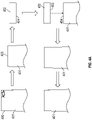
FIG. 4B is a perspective view of removal/bonding operations ofFIG. 4A in accordance with embodiments -
FIG. 5 is a schematic illustration of a crystallographic orientation of a replacement section in accordance with embodiments; -
FIG. 6 is a schematic illustration of alignment features of a replacement section in accordance with embodiments; -
FIG. 7 is a schematic illustration of a milling of a section of a turbine vane or platform of a gas turbine engine in accordance with embodiments; and -
FIG. 8 is a flow diagram illustrating a method of repair of a part in accordance with further embodiments. -
FIG. 1 schematically illustrates agas turbine engine 20. Thegas turbine engine 20 is disclosed herein as a two-spool turbofan that generally incorporates a fan section 22, acompressor section 24, acombustor section 26 and aturbine section 28. Alternative engines might include other systems or features. The fan section 22 drives air along a bypass flow path B in a bypass duct, while thecompressor section 24 drives air along a core flow path C for compression and communication into thecombustor section 26 then expansion through theturbine section 28. Although depicted as a two-spool turbofan gas turbine engine in the disclosed non-limiting embodiment, it should be understood that the concepts described herein are not limited to use with two-spool turbofans as the teachings may be applied to other types of turbine engines including three-spool architectures. - The
exemplary engine 20 generally includes alow speed spool 30 and ahigh speed spool 32 mounted for rotation about an engine central longitudinal axis A relative to an enginestatic structure 36 viaseveral bearing systems 38. It should be understood thatvarious bearing systems 38 at various locations may alternatively or additionally be provided, and the location ofbearing systems 38 may be varied as appropriate to the application. - The
low speed spool 30 generally includes aninner shaft 40 that interconnects afan 42, alow pressure compressor 44 and alow pressure turbine 46. Theinner shaft 40 is connected to thefan 42 through a speed change mechanism, which in exemplarygas turbine engine 20 is illustrated as a gearedarchitecture 48 to drive thefan 42 at a lower speed than thelow speed spool 30. Thehigh speed spool 32 includes anouter shaft 50 that interconnects ahigh pressure compressor 52 andhigh pressure turbine 54. Acombustor 56 is arranged inexemplary gas turbine 20 between thehigh pressure compressor 52 and thehigh pressure turbine 54. An enginestatic structure 36 is arranged generally between thehigh pressure turbine 54 and thelow pressure turbine 46. The enginestatic structure 36 further supports bearingsystems 38 in theturbine section 28. Theinner shaft 40 and theouter shaft 50 are concentric and rotate viabearing systems 38 about the engine central longitudinal axis A which is collinear with their longitudinal axes. - The core airflow is compressed by the
low pressure compressor 44 then thehigh pressure compressor 52, mixed and burned with fuel in thecombustor 56, then expanded over thehigh pressure turbine 54 andlow pressure turbine 46. Theturbines low speed spool 30 andhigh speed spool 32 in response to the expansion. It will be appreciated that each of the positions of the fan section 22,compressor section 24,combustor section 26,turbine section 28, and fandrive gear system 48 may be varied. For example,gear system 48 may be located aft ofcombustor section 26 or even aft ofturbine section 28, and fan section 22 may be positioned forward or aft of the location ofgear system 48. - The
engine 20 in one example is a high-bypass geared aircraft engine. In a further example, theengine 20 bypass ratio is greater than about six (6), with an example embodiment being greater than about ten (10), the gearedarchitecture 48 is an epicyclic gear train, such as a planetary gear system or other gear system, with a gear reduction ratio of greater than about 2.3 and thelow pressure turbine 46 has a pressure ratio that is greater than about five. In one disclosed embodiment, theengine 20 bypass ratio is greater than about ten (10:1), the fan diameter is significantly larger than that of thelow pressure compressor 44, and thelow pressure turbine 46 has a pressure ratio that is greater than about five 5:1.Low pressure turbine 46 pressure ratio is pressure measured prior to inlet oflow pressure turbine 46 as related to the pressure at the outlet of thelow pressure turbine 46 prior to an exhaust nozzle. The gearedarchitecture 48 may be an epicycle gear train, such as a planetary gear system or other gear system, with a gear reduction ratio of greater than about 2.3:1. It should be understood, however, that the above parameters are only exemplary of one embodiment of a geared architecture engine and that the present disclosure is applicable to other gas turbine engines including direct drive turbofans. - A significant amount of thrust is provided by the bypass flow B due to the high bypass ratio. The fan section 22 of the
engine 20 is designed for a particular flight condition--typically cruise at about 0.8Mach and about 35,000 feet (10,688 meters). The flight condition of 0.8 Mach and 35,000 ft (10,688 meters), with the engine at its best fuel consumption--also known as "bucket cruise Thrust Specific Fuel Consumption ('TSFC')"--is the industry standard parameter of lbm of fuel being burned divided by lbf of thrust the engine produces at that minimum point. "Low fan pressure ratio" is the pressure ratio across the fan blade alone, without a Fan Exit Guide Vane ("FEGV") system. The low fan pressure ratio as disclosed herein according to one non-limiting embodiment is less than about 1.45. "Low corrected fan tip speed" is the actual fan tip speed in ft/sec divided by an industry standard temperature correction of [(Tram °R)/(518.7 °R)]0.5. The "Low corrected fan tip speed" as disclosed herein according to one non-limiting embodiment is less than about 1150 ft/second (350.5 m/sec). - Field assisted sintering technology (FAST) and spark plasma sintering (SPS) are consolidation processes that are executed at temperatures lower than the melting point of the subject materials. Similar to hot pressing, FAST forms bonds between materials but at temperatures ∼200°C lower. FAST utilizes a high amperage pulsed direct current (DC) electrical current to heat the subject materials to be bonded through Joule heating while under uniaxial compression. The consolidation is a combination of solid-state transport mechanisms including primarily diffusion and creep. The result is a metallurgical bond between the materials to be joined. Consolidation or joining can be accomplished in a variety of conductive and nonconductive materials and forms.
- FAST is advantageous over other sources of bonding such as diffusional bonding, dual alloy casting, brazing, transient liquid phase bonding or welding under high temperature protective atmosphere. Some of the advantages of FAST over these other methods are detailed below.
- Diffusional bonding does not use (is devoid of) the application of a DC current for heating that enhances bond line diffusion. It however uses a much higher temperature (than temperatures used in FAST) and a longer bonding cycle than FAST but is also conducted below the melting point of the alloy. Due to the higher temperatures and longer cycles, diffusional bonding can result in aging of the alloys (e.g., coursing of gamma prime phase in nickel-based alloys) or detrimental feature formations (e.g., recrystallization in single crystal alloys) that are generally considered detrimental.
- Dual alloy casting includes casting a first piece then remelting an interface and casting a second piece onto the molten portion of the first piece. This process is typically conducted above a melting point of the subj ect alloy as it is a method that includes casting (pouring of a molten metal).
- In FAST, it is easier to locate the bond line (between the first portion and the second portion) with high precision as it relies on machining of two pieces to a specific shape with little or no displacement of that contact surface thereafter. Dual casting relies on a partial fill of the first casting, remelting of the interface and a mixing of the interface thereby making the bond line location more variable. Metallurgy of the bond line is going to be a composite of the alloys selected as they will undergo mixing in the melt or in a partially molten state. This may result in the formation of deleterious phases as a result of dissimilar alloy combinations. These deleterious phases will come out (i.e., precipitate) much more quickly and over larger zone sizes in dual alloy casting.
- Brazing requires low melt alloy (in the case of nickel superalloy bonding commonly a boron or silicon enriched alloy) to be placed between two alloys to be bonded. The low melt alloy is melted and then solidified forming the joint between the two alloys. A capability of the joint is dependent on the low melt alloy which will have obviously lower temperature capability but also generally lower mechanical and environmental properties as it is selected for its melt point. It therefore includes mechanical and environmental properties. The strength of brazed joints is generally low (typically no greater than a few kilopounds per square inch (KSI)). Brazing has a much lower performance capability than FAST or dual alloy casting.
- Transient Liquid Phase (TLP) bonding is similar to brazing but uses more complex alloys (in lieu of the low melt alloy using in brazing) and uses more complete mixing during the diffusion cycle. This results in generally higher mechanical and environmental capabilities over brazing but significantly less than the individual alloys used to form the bond. TLP has a much lower expected capability than FAST or dual alloy casting.
- Welding high temperature protective atmosphere (example includes superalloy welding at elevated temperature or SWET) involves welding and therefore requires melting of the alloy and consequent re-solidification. The bond line between the two alloys will be a welded feature with an equiaxed grain structure and associated weld defects (e.g., quench cracking is one common challenge). The bond line will have its own unique capability and be different than the alloys bonded. This technique (SWET) is not capable of maintaining a single crystal continuous structure and therefore is a detriment in physical and environmental properties.
- In summary, FAST is advantageous over these other methods because it can retain the single crystal characteristics across the bond line and because it can facilitate retention of the structure that existed before the bonding process to retain material performance of the alloys involved and to maximize the performance across the bond line. It also results in a continuum of structure (e.g., crystalline structure) from the first portion to the second portion after the bonding process.
- As will be described below, an engine component returned from service with distress (e.g., environmental attack or TMF cracking) is removed from its parent component by grinding away the damaged material along a continuous plane. For a turbine blade, this could optionally be to grind back the tip to a lower span line (either above or below the tip shelf). For a BOAS, this could be to grind along a circumferential plane inwardly from the gas path surface. A replacement shape, similar to the geometry of the material removed by grinding, is single crystal cast using investment cast methods. The mating surfaces are ground and cleaned to ensure good contact. The surfaces are bonded using the FAST method. The component is then coated and finished for reuse in service. Alignment features may be included in the newly cast feature for alignment in the FAST process that will be later ground off prior to finishing.
- With reference to
FIG. 2 , amethod 200 of repair of a part, such as a turbine blade, a blade outer seal (BOAS) or a turbine vane or platform of thegas turbine engine 20 ofFIG. 1 is provided. As shown inFIG. 2 , the method includes removing a section that is damaged from the part (201), casting a replacement section for the part, the replacement section having a geometry similar to that of the section in an undamaged condition (202) and bonding the replacement section to the part using FAST (203). In accordance with embodiments, themethod 200 can further include at least one of coating and finishing the part and the replacement section bonded thereto (204). - Where the part includes or is provided as a turbine blade, the removing of the section of
operation 201 can include grinding a tip of the turbine blade back to a lower span line and in some cases beyond tip shelf regions and into span regions that expose or open up internal cooling circuit features. Where the part includes or is provided as a BOAS, the removing of the section ofoperation 201 can include grinding along a circumferential plane in from a gas path surface and again, in some cases, beyond tip shelf regions and into span regions that expose or open up internal cooling circuit features. Where the part includes or is provided as a turbine vane or a platform, the removing of the section ofoperation 201 can include or be provided as a milling of the section out of the turbine vane or the platform. The casting of the replacement section ofoperation 202 can include a single crystal casting of the replacement section. - The bonding of the replacement section to the part of
operation 203 can include at least one of crystallographic aligning of the replacement section with the part (in which the crystal structure of the replacement section aligns or substantially aligns with the crystal structure of the part) and mechanical aligning of the replacement section with the part (in which internal and external features of the replacement section align or substantially align with corresponding internal and external features of the part). The crystallographic aligning can include using tooling to establish and maintain crystallographic alignment to a predefined angular tolerance (e.g., ∼10° or less) between the part and the replacement section. To the extent that the mechanical aligning involves the internal and external features of the replacement section aligning or substantially aligning with the corresponding internal and external features of the part, it is to be understood that at least the external features can be machined or otherwise detailed and finished following bonding. Also, the mechanical aligning can include adding alignment features to the part and the replacement section to aid with alignment. The alignment features can be removed following thebonding operation 203. - The bonding of the replacement section to the part of
operation 203 can include preparing a bond surface of the part and a corresponding bond surface of the replacement section by at least one of grinding and cleaning so that the bond surface and the corresponding bond surface can be reliably fit together to form a bond line with little to no defects. - With reference to
FIGS. 3 and4A and4B , amethod 300 of repair of a turbine blade or a blade outer seal (BOAS) of a gas turbine engine is provided. As shown inFIG. 3 , themethod 300 includes grinding asection 400 that is damaged from the turbine blade or the BOAS 401 (301). This can be done by either grinding a tip of the turbine blade back to a lower span line in the case of the turbine blade or grinding along a circumferential plane in from a gas path surface in the case of the BOAS as illustrated generally in the illustration of thesection 400 being removed from the turbine blade or theBOAS 401 inFIGS. 4A and4B . Themethod 300 further includes casting areplacement section 402 for the turbine blade or theBOAS 402 by, e.g., single crystal casting of thereplacement section 402, where thereplacement section 402 has a geometry similar to that of thesection 400 in an undamaged condition (302) and preparing abond surface 403 of the turbine blade or theBOAS 401 and acorresponding bond surface 404 of thereplacement section 402 for bonding by at least one of grinding and cleaning (303). The method further includes bonding thereplacement section 402 to the turbine blade or theBOAS 401 using FAST at thebond surface 403 of the turbine blade or theBOAS 401 and thecorresponding bond surface 404 of the replacement section 402 (304) and at least one of coating and finishing the turbine blade or theBOAS 401 and thereplacement section 402 bonded thereto (305). - With reference to
FIGS. 5 and 6 , the bonding of thereplacement section 402 to the turbine blade or theBOAS 401 ofoperation 304 can include at least one of crystallographic aligning of thereplacement section 402 with the turbine blade or the BOAS 401 (seeFIG. 5 ) and mechanical aligning of the replacement section with turbine blade or the BOAS 401 (seeFIG. 6 ). For the case of the crystallographic aligning, as shown inFIG. 5 , the method can include using tooling to establish and maintain a crystallographic alignment between the turbine blade orBOAS 401 and thereplacement section 402 to within a predefined angular tolerance (e.g., ∼10° or less). For the case of the mechanical aligning, as shown inFIG. 6 , the method can include adding alignment features 601 and 602 to the turbine blade or theBOAS 401 and thereplacement section 402, respectively, to aid with alignment and removing the alignment features 601 and 602 following the bonding ofoperation 304. In any case, the crystallographic aligning and the mechanical aligning can include maintaining pressure between thereplacement section 402 and the turbine blade or theBOAS 401 in a single direction (i.e., along a single axial plane). - With reference to
FIG. 7 , a method of repair of a turbine vane or platform of a gas turbine engine is provided and is generally similar to themethod 300 described above with reference toFIGS. 3-6 except as described herein. As shown inFIG. 7 , the method includes milling asection 700 that is damaged out of the turbine vane orplatform 701, casting a replacement section (see above), preparing a bond surface of the turbine vane or platform and a corresponding bond surface of the replacement section (see above) and bonding the replacement section to the turbine vane or platform using FAST at the bond surface and the corresponding bond surface (see above). - In accordance with additional embodiments and with reference back to
FIGS. 2, 3 and7 and additional reference toFIG. 8 , the methods described herein can further include a coating or enhancement of a part and a replacement section prior to the bonding ofoperation 203 ofFIG. 2 and the bonding ofoperation 304 ofFIG. 3 . For example, turbine blade tip features can be damaged due to hot corrosion and coating processes are limited in effectiveness for protecting internal surfaces of a full cast turbine blade. However, if an internal (or external) feature is newly exposed by the removing ofoperation 201 ofFIG. 2 , the grinding ofoperation 301 ofFIG. 3 or the milling operation ofFIG. 7 , line-of-sight (LOS) processing is possible. In these or other cases, additional or alternative coating processes for those newly exposed internal (or external) features can become available as options (801). These processes could include thermal spraying or physical vapor deposition (PVD) of MCrAlY materials or the like that have superior corrosion resistance as compared with a diffusion aluminide. - In an embodiment, a first alloy for use in the methods described herein may be a "high strength" metal alloy. Examples of the first alloy include Alloy D, René N5, CMSX-4, CMSX-10, TMS-138 or TMS-162. The metal alloys are nickel-based metals that in addition to nickel comprise one or more of chromium, cobalt, molybdenum, aluminum, titanium, tantalum, niobium, ruthenium, rhenium, boron and carbon. The metal alloys contain one or more of the following metals in addition to nickel - 2 to 10 wt% of chromium, 2 to 11 wt% of cobalt, 0.5 to 5 wt% molybdenum, 4 to 7.5 wt% of tungsten, 3 - 7 wt% of aluminum, 0 to 5 wt% of titanium, 3 to 10 wt% of tantalum and 2 - 8 wt% of rhenium. The metal alloys may also contain ruthenium, carbon and boron.
- The composition of these alloys is defined to maximize mechanical properties in a single crystal form while maintaining an adequate level of environmental resistance. Table 1 and Table 2 shows preferred ranges (of the ingredients) for the compositions (in weight percent) that may be used for the first alloy. Table 2 contains broader ranges for some of the alloys (than those indicated in Table 1) that may be used in the first portion.
TABLE 1. ALLOY COMPOSITION (WT.%) Cr Co Mo W Al Ti Ta Nb Re Ru Hf C B Zr Ni IN-713LC 12 - 4.5 - 5.9 0.6 - 2 - - - 0.05 0.01 0.1 BAL IN-738LC 16 8.5 1.75 2.6 3.4 3.4 1.75 0.9 - - - 0.11 0.01 0.04 BAL RENE 80 14 9 4 4 3 4.7 - - - - 0.8 0.16 0.015 0.01 BAL MAR-M247 8 10 0.6 10 5.5 1 3 - - - 1.5 0.15 0.015 0.03 BAL MAR-M200HF 8 9 - 12 5 1.9 - 1 - - 2 0.13 0.015 0.03 BAL CM247LC 8.1 9.2 0.5 9.5 5.6 0.7 3.2 - - - 1.4 0.07 0.015 0.007 BAL CM186LC 6 9.3 0.5 8.4 5.7 0.7 3.4 - 3.0 - 1.4 0.07 0.015 0.005 BAL ALLOY A 6.5 10 1.7 6.5 6 - 4 - 3.0 - 1.5 0.1 0.015 0.1 BAL CMSX-2 8 5 0.6 8 5.6 1 6 - - - - - - - BAL ALLOY B 10 5 - 4 5 1.5 12 - - - - - - - BAL RENE N4 9 8 2 6 3.7 4.2 4 0.5 - - - - - - BAL AM1 7 8 2 5 5 1.8 8 1 - - - - - - BAL RR2000 10 15 3 - 5.5 4 - - - - - - - - BAL CMSX-4 6.5 9.6 0.6 6.4 5.6 1 6.5 - 3 - 0.1 - - - BAL ALLOY C 5 10 2 6 5.6 - 9 - 3 - 0.1 - - - BAL RENE N5 7 8 2 5 6.2 - 7 - 3 - 0.2 - - - BAL CMSX-10 2 3 0.4 5 5.7 0.2 8 - 6 - 0.03 - - - BAL TMS-138 2.9 5.9 2.9 5.9 5.9 - 5.6 - 4.9 2 0.1 - - - BAL TMS-162 2.9 5.8 3.9 5.8 5.8 - 5.6 - 4.9 6 0.09 - - BAL CMSX-7 6 10 0.6 9 5.7 0.8 9 - - - 0.2 - - - BAL CMSX-8 5.4 10 0.6 8 5.7 0.7 8 - 1.5 - 0.1 - - - BAL Table 2 Cr Co Mo w Al Ti Ta Nb Re Ni Alloy D 5-7 9-11 1.5-2.5 5.5-7.5 5-7 - 3-10 - 2-4 Balance René N5 6-10 7-9 1.5-2.5 4-7 3-7 0-5 3-8 0-1 0-4 Balance CMSX-4 4-8 7-10 0.5-1.5 5.5-7.5 5-6 0-2 5-8 - 2-4 balance CMSX-10 1-3 2-4 0.1-1 4-6 5-7 0.1-0.4 6-10 4-8 balance TMS-138 2-4 3.5-6.5 2-4 5-7 5-7 - 5-7 4-6 balance TMS-162 2-4 3.5-6.5 3-5 5-7 5-7 - 5-7 5-7 balance - The high strength alloys can withstand stresses of greater than 800 MPa at temperatures greater than 600°C and stresses of greater than 200 MPa at temperatures of greater than 800°C.
- Second alloys for use in the methods described herein are selected for their ability to handle harsh environmental conditions and can include René 195 and René N2. These compositions were developed with an eye to improved environmental resistance. This can be seen in the Al and Cr levels as compared with Re, W, Mo shown in the Table 3. The cobalt to chromium ratios are lower for the second alloys, while the aluminum to cobalt ratio is much higher for the second alloys when compared with the first alloys.
- The second alloys can be a nickel-based alloy that in addition to nickel includes one or more of chromium, cobalt, molybdenum, aluminum, titanium, tantalum, niobium, ruthenium, rhenium, boron and carbon. The metal alloys contain one or more of the following metals in addition to nickel - 7 to 14 wt% of chromium, 3 to 9 wt% of cobalt, 0.1 to 0.2 wt% molybdenum, 3 to 5 wt% of tungsten, 6 - 9 wt% of aluminum, 0 to 5 wt% of titanium, 4 to 6 wt% of tantalum, 0.1 to 0.2 wt% f hafnium and 1 - 2 wt% of rhenium. The metal alloys may also contain ruthenium, carbon and boron.
Table 3 Cr Co Al Ta Mo w Re Hf Ni René 195 7-9 3-4 7-9 5-6 0.1-0.2 3-5 1-2 0.1-0.2 balance René N2 12-14 7-9 6-8 4-6 3-4 1-2 0.1-0.2 balance - The high strength alloys used in the second alloys can withstand stresses of at least 50% of the first alloys. In an embodiment, the high strength alloys used in the second alloys are environmentally resistant and withstand temperatures of greater than 1200°C (under oxidation conditions) while undergoing less than 0.05 grams of weight loss per unit weight.
- Technical effects and benefits of the present disclosure are the provision of restoration of damaged components with substrate-capable materials as opposed to equiaxed, welded materials as well as a capability for repairs to relatively large damage areas. FAST-bonded restoration processes will yield a relatively high-performing repair feature which will likely increase 2nd time shop yields. Additionally, FAST-bonded restorations may enable repair of components that would otherwise have been scrapped due to the size of the damage zones.
- The corresponding structures, materials, acts, and equivalents of all means or step plus function elements in the claims below are intended to include any structure, material, or act for performing the function in combination with other claimed elements as specifically claimed. The description of the present disclosure has been presented for purposes of illustration and description, but is not intended to be exhaustive or limited to the technical concepts in the form disclosed. Many modifications and variations will be apparent to those of ordinary skill in the art without departing from the scope and spirit of the disclosure. The embodiments were chosen and described in order to best explain the principles of the disclosure and the practical application, and to enable others of ordinary skill in the art to understand the disclosure for various embodiments with various modifications as are suited to the particular use contemplated.
- While the preferred embodiments to the disclosure have been described, it will be understood that those skilled in the art, both now and in the future, may make various improvements and enhancements which fall within the scope of the claims which follow. These claims should be construed to maintain the proper protection for the disclosure first described.
Claims (12)
- A method of repair of a part (401; 701), the method comprising:removing a section (400; 700) that is damaged from the part (401; 701);casting a replacement section (402) for the part (401; 701), the replacement section (402) having a geometry similar to that of the section (400; 700) in an undamaged condition; andbonding the replacement section (402) to the part (401; 701) using field assisted sintering technology (FAST).
- The method according to claim 1, wherein at least one of:the part (401) comprises a turbine blade of a gas turbine engine and the removing of the section (400) comprises grinding a tip of the turbine blade back to a lower span line,the part (401) comprises a blade outer air seal (BOAS) of a gas turbine engine and the removing of the section (400) comprises grinding along a circumferential plane in from a gas path surface, andthe part (701) comprises a turbine vane or a platform of a gas turbine engine and the removing of the section (700) comprises milling.
- The method according to claim 1 or 2, wherein the bonding of the replacement section (402) to the part (401) comprises preparing a bond surface (404) of the part and a corresponding bond surface (403) of the replacement section (402) by at least one of grinding and cleaning.
- The method according to any of claims 1 to 3, wherein the casting of the replacement section (402) comprises a single crystal casting of the replacement section (402).
- The method according to any preceding claim, wherein, following the removing and prior to the bonding, the method further comprises coating features of the part (401; 701) which are exposed by the removing.
- The method according to any preceding claim, wherein the bonding of the replacement section (402) to the part (401; 701) comprises at least one of crystallographic aligning and mechanical aligning of the replacement section (402) with the part (401; 701).
- The method according to any preceding claim, further comprising at least one of coating and finishing the part (401; 701) and the replacement section (402) bonded thereto.
- The method according to any of claims 1 or 4 to 7, wherein:the part (401) comprises a turbine blade or a blade outer air seal (BOAS) of a gas turbine engine;the removing of the section (400) comprises grinding the section (400) that is damaged from the turbine blade or the BOAS; andthe method further comprises preparing a bond surface (404) of the turbine blade or the BOAS and a corresponding bond surface (403) of the replacement section (402) for bonding, and bonding the replacement section (402) to the turbine blade or the BOAS using field assisted sintering technology (FAST) at the bond surface (404) of the turbine blade or the BOAS and the corresponding bond surface (403) of the replacement section (402).
- The method according to claim 8, wherein:
for the turbine blade, the grinding comprises grinding a tip of the turbine blade back to a lower span line, and for the BOAS, the grinding comprises grinding along a circumferential plane in from a gas path surface. - The method according to claim 8 or 9, wherein the preparing of the bond surface (404) of the turbine blade or the BOAS and the corresponding bond surface (403) of the replacement section (402) comprises at least one of grinding and cleaning.
- The method according to any of claims 1 or 4 to 7, wherein:the part (701) comprises a turbine vane or platform of a gas turbine engine;the removing of the section (700) comprises milling the section (700) that is damaged out of the turbine vane or the platform; andthe method further comprises preparing a bond surface of the turbine vane or the platform and a corresponding bond surface of the replacement section for bonding, and bonding the replacement section to the turbine vane or the platform using field assisted sintering technology (FAST) at the bond surface of the turbine vane or the platform and the corresponding bond surface of the replacement section.
- The method according to claim 11, wherein the preparing of the bond surface of the turbine vane or the platform and the corresponding bond surface of the replacement section comprises at least one of grinding and cleaning.
Applications Claiming Priority (2)
| Application Number | Priority Date | Filing Date | Title |
|---|---|---|---|
| US202163212325P | 2021-06-18 | 2021-06-18 | |
| US202163232963P | 2021-08-13 | 2021-08-13 |
Publications (2)
| Publication Number | Publication Date |
|---|---|
| EP4105438A1 true EP4105438A1 (en) | 2022-12-21 |
| EP4105438B1 EP4105438B1 (en) | 2026-04-08 |
Family
ID=82115785
Family Applications (1)
| Application Number | Title | Priority Date | Filing Date |
|---|---|---|---|
| EP22179741.8A Active EP4105438B1 (en) | 2021-06-18 | 2022-06-17 | Bonding method for the repair of a gas turbine engine part |
Country Status (2)
| Country | Link |
|---|---|
| US (1) | US12529316B2 (en) |
| EP (1) | EP4105438B1 (en) |
Cited By (1)
| Publication number | Priority date | Publication date | Assignee | Title |
|---|---|---|---|---|
| EP4375482A1 (en) * | 2022-11-23 | 2024-05-29 | RTX Corporation | Systems and methods of blade leading edge repair using field assisted sintering technology |
Families Citing this family (6)
| Publication number | Priority date | Publication date | Assignee | Title |
|---|---|---|---|---|
| EP4105450A1 (en) | 2021-06-18 | 2022-12-21 | Raytheon Technologies Corporation | Passive clearance control (apcc) system produced by field assisted sintering technology (fast) |
| US12055056B2 (en) | 2021-06-18 | 2024-08-06 | Rtx Corporation | Hybrid superalloy article and method of manufacture thereof |
| EP4105449A1 (en) | 2021-06-18 | 2022-12-21 | Raytheon Technologies Corporation | Hybrid bonded configuration for blade outer airseal (boas) |
| EP4105438B1 (en) | 2021-06-18 | 2026-04-08 | RTX Corporation | Bonding method for the repair of a gas turbine engine part |
| EP4105444A1 (en) * | 2021-06-18 | 2022-12-21 | Raytheon Technologies Corporation | Joining individual turbine vanes with field assisted sintering technology (fast) |
| US20240263557A1 (en) * | 2022-09-21 | 2024-08-08 | Raytheon Technologies Corporation | Systems and methods of blade tip repair and manufacturing using field assisted sintering |
Citations (9)
| Publication number | Priority date | Publication date | Assignee | Title |
|---|---|---|---|---|
| US6384365B1 (en) * | 2000-04-14 | 2002-05-07 | Siemens Westinghouse Power Corporation | Repair and fabrication of combustion turbine components by spark plasma sintering |
| EP1332824A2 (en) * | 2002-01-30 | 2003-08-06 | Hitachi Ltd. | Method for manufacturing turbine blade and manufactured turbine blade |
| US20050091848A1 (en) * | 2003-11-03 | 2005-05-05 | Nenov Krassimir P. | Turbine blade and a method of manufacturing and repairing a turbine blade |
| EP2078579A1 (en) * | 2008-01-10 | 2009-07-15 | Siemens Aktiengesellschaft | Method for soldering one component and component with soldering and welding points |
| US20140263579A1 (en) * | 2013-03-14 | 2014-09-18 | Anand A. Kulkarni | Method and apparatus for fabrication and repair of thermal barriers |
| WO2015122953A2 (en) * | 2013-11-25 | 2015-08-20 | Siemens Energy, Inc. | Use of spark plasma sintering for manufacturing superalloy compound components |
| DE102014206827A1 (en) * | 2014-04-09 | 2015-10-15 | Siemens Aktiengesellschaft | Method of joining and gas turbine component |
| EP3848555A1 (en) * | 2020-01-07 | 2021-07-14 | Raytheon Technologies Corporation | Multi-alloy turbine engine components and manufacture methods |
| EP3865664A1 (en) * | 2020-02-14 | 2021-08-18 | Raytheon Technologies Corporation | Multi-zone blade fabrication |
Family Cites Families (64)
| Publication number | Priority date | Publication date | Assignee | Title |
|---|---|---|---|---|
| US3394918A (en) | 1966-04-13 | 1968-07-30 | Howmet Corp | Bimetallic airfoils |
| DE3786266T2 (en) | 1987-09-30 | 1993-12-02 | Ibm | Device for connecting a data processing device to a telephone network. |
| DE4219469A1 (en) | 1992-06-13 | 1993-12-16 | Asea Brown Boveri | Component subject to high temperatures, in particular turbine blade, and method for producing this component |
| US5264011A (en) | 1992-09-08 | 1993-11-23 | General Motors Corporation | Abrasive blade tips for cast single crystal gas turbine blades |
| US5636439A (en) | 1995-05-22 | 1997-06-10 | General Electric Co. | Methods for coating and securing multi-vane nozzle segments |
| DE29715180U1 (en) | 1997-08-23 | 1997-10-16 | MTU Motoren- und Turbinen-Union München GmbH, 80995 München | Guide blade for a gas turbine |
| DE69927594T2 (en) | 1999-11-03 | 2006-07-20 | Alstom Technology Ltd | Process for coating and welding guide vanes of a gas turbine |
| US6847004B2 (en) | 2003-01-10 | 2005-01-25 | General Electric Company | Process of removing a ceramic coating deposit in a surface hole of a component |
| US7441331B2 (en) | 2004-08-26 | 2008-10-28 | United Technologies Corporation | Turbine engine component manufacture methods |
| US7140835B2 (en) | 2004-10-01 | 2006-11-28 | General Electric Company | Corner cooled turbine nozzle |
| US7510370B2 (en) | 2005-02-01 | 2009-03-31 | Honeywell International Inc. | Turbine blade tip and shroud clearance control coating system |
| US7371049B2 (en) | 2005-08-31 | 2008-05-13 | United Technologies Corporation | Manufacturable and inspectable microcircuit cooling for blades |
| US7341427B2 (en) | 2005-12-20 | 2008-03-11 | General Electric Company | Gas turbine nozzle segment and process therefor |
| DE102006033799A1 (en) | 2006-07-19 | 2008-01-24 | Mtu Aero Engines Gmbh | Method of repairing turbine blades |
| US20090183850A1 (en) | 2008-01-23 | 2009-07-23 | Siemens Power Generation, Inc. | Method of Making a Combustion Turbine Component from Metallic Combustion Turbine Subcomponent Greenbodies |
| US8267663B2 (en) | 2008-04-28 | 2012-09-18 | Pratt & Whitney Canada Corp. | Multi-cast turbine airfoils and method for making same |
| US8231354B2 (en) | 2009-12-15 | 2012-07-31 | Siemens Energy, Inc. | Turbine engine airfoil and platform assembly |
| FR2972379B1 (en) | 2011-03-07 | 2014-01-17 | Snecma | METHOD FOR LOCALLY RECHARGING DAMAGED THERMOMECHANICAL PIECE AND PART THEREFORE PRODUCED, IN PARTICULAR TURBINE PIECE |
| US9151179B2 (en) | 2011-04-13 | 2015-10-06 | General Electric Company | Turbine shroud segment cooling system and method |
| FR2981590B1 (en) | 2011-10-21 | 2014-06-06 | Snecma | METHOD OF MAKING A SINTERED PREFORM AND ASSEMBLING THE PREFORM ON A WORKPIECE |
| US8683813B2 (en) | 2012-02-15 | 2014-04-01 | United Technologies Corporation | Multi-lobed cooling hole and method of manufacture |
| US9127549B2 (en) | 2012-04-26 | 2015-09-08 | General Electric Company | Turbine shroud cooling assembly for a gas turbine system |
| US9700941B2 (en) | 2012-10-03 | 2017-07-11 | Siemens Energy, Inc. | Method for repairing a component for use in a turbine engine |
| WO2014093826A2 (en) | 2012-12-14 | 2014-06-19 | United Technologies Corporation | Multi-shot casting |
| EP3513889B1 (en) | 2012-12-14 | 2021-04-14 | Raytheon Technologies Corporation | Alloy and hybrid turbine blade for improved engine performance or architecture |
| US9015944B2 (en) | 2013-02-22 | 2015-04-28 | General Electric Company | Method of forming a microchannel cooled component |
| US9782862B2 (en) | 2013-03-15 | 2017-10-10 | Siemens Energy, Inc. | Component repair using brazed surface textured superalloy foil |
| EP2971519B1 (en) | 2013-03-15 | 2020-10-28 | United Technologies Corporation | Method for working airfoil clusters of a gas turbine engine |
| EP2969363B1 (en) | 2013-03-15 | 2020-11-04 | United Technologies Corporation | Method for working an airfoil cluster |
| US10053999B2 (en) | 2013-04-18 | 2018-08-21 | United Technologies Corporation | Radial position control of case supported structure with axial reaction member |
| US9656321B2 (en) | 2013-05-15 | 2017-05-23 | General Electric Company | Casting method, cast article and casting system |
| US9802248B2 (en) | 2013-07-31 | 2017-10-31 | United Technologies Corporation | Castings and manufacture methods |
| US10065239B2 (en) | 2013-09-17 | 2018-09-04 | United Technologies Corporation | Casting molds, manufacture and use methods |
| EP3047103B1 (en) | 2013-09-17 | 2020-09-30 | United Technologies Corporation | Turbine blades and manufacture methods |
| US10145245B2 (en) | 2013-09-24 | 2018-12-04 | United Technologies Corporation | Bonded multi-piece gas turbine engine component |
| WO2015069338A2 (en) | 2013-10-07 | 2015-05-14 | United Technologies Corporation | Gas turbine engine blade outer air seal thermal control system |
| EP3080401B1 (en) | 2013-11-08 | 2020-10-14 | United Technologies Corporation | Bonded multi-piece gas turbine engine component |
| US9803939B2 (en) | 2013-11-22 | 2017-10-31 | General Electric Company | Methods for the formation and shaping of cooling channels, and related articles of manufacture |
| EP3074159A4 (en) | 2013-11-27 | 2017-08-02 | United Technologies Corporation | Method and apparatus for manufacturing a multi-alloy cast structure |
| US10323535B2 (en) | 2013-12-10 | 2019-06-18 | United Technologies Corporation | Blade tip clearance systems |
| US10316683B2 (en) | 2014-04-16 | 2019-06-11 | United Technologies Corporation | Gas turbine engine blade outer air seal thermal control system |
| US10267156B2 (en) | 2014-05-29 | 2019-04-23 | General Electric Company | Turbine bucket assembly and turbine system |
| US9844826B2 (en) | 2014-07-25 | 2017-12-19 | Honeywell International Inc. | Methods for manufacturing a turbine nozzle with single crystal alloy nozzle segments |
| DE102014226370A1 (en) | 2014-12-18 | 2016-06-23 | Siemens Aktiengesellschaft | Method for generative production of a workpiece from a raw material |
| US9976435B2 (en) | 2014-12-19 | 2018-05-22 | United Technologies Corporation | Blade tip clearance systems |
| US10337353B2 (en) | 2014-12-31 | 2019-07-02 | General Electric Company | Casing ring assembly with flowpath conduction cut |
| US9885247B2 (en) | 2015-05-19 | 2018-02-06 | United Technologies Corporation | Support assembly for a gas turbine engine |
| FR3048629B1 (en) | 2016-03-14 | 2018-04-06 | Centre National De La Recherche Scientifique | PROCESS FOR MANUFACTURING A TURBINE RING FOR TURBOMACHINE |
| FR3048630B1 (en) | 2016-03-14 | 2020-02-21 | Centre National De La Recherche Scientifique | PROCESS FOR MANUFACTURING AN ABRADABLE PLATE AND FOR REPAIRING A TURBINE RING |
| US20180223681A1 (en) | 2017-02-09 | 2018-08-09 | General Electric Company | Turbine engine shroud with near wall cooling |
| US10618109B2 (en) | 2017-08-07 | 2020-04-14 | General Electric Company | Hybrid pre-sintered preform, green preform, and process |
| EP3575016A1 (en) | 2018-06-01 | 2019-12-04 | Siemens Aktiengesellschaft | Improvements relating to the manufacture of superalloy components |
| EP3575424A1 (en) | 2018-06-01 | 2019-12-04 | Siemens Aktiengesellschaft | Improvements relating to superalloy components |
| US11203064B2 (en) * | 2018-08-21 | 2021-12-21 | Siemens Energy, Inc. | Section replacement of a turbine airfoil with a metallic braze presintered preform |
| US11318553B2 (en) | 2019-01-04 | 2022-05-03 | Raytheon Technologies Corporation | Additive manufacturing of laminated superalloys |
| US11643948B2 (en) | 2019-02-08 | 2023-05-09 | Raytheon Technologies Corporation | Internal cooling circuits for CMC and method of manufacture |
| US11414355B2 (en) | 2019-03-21 | 2022-08-16 | Raytheon Technologies Corporation | Systems and methods for additively manufactured ceramic composites |
| FR3099787B1 (en) | 2019-08-05 | 2021-09-17 | Safran Helicopter Engines | Ring for a turbomachine or turbine engine turbine |
| US11634989B2 (en) * | 2020-04-27 | 2023-04-25 | Raytheon Technologies Corporation | Methods and assemblies for bonding airfoil components together |
| EP4105449A1 (en) | 2021-06-18 | 2022-12-21 | Raytheon Technologies Corporation | Hybrid bonded configuration for blade outer airseal (boas) |
| EP4105438B1 (en) | 2021-06-18 | 2026-04-08 | RTX Corporation | Bonding method for the repair of a gas turbine engine part |
| US12055056B2 (en) | 2021-06-18 | 2024-08-06 | Rtx Corporation | Hybrid superalloy article and method of manufacture thereof |
| US20220403742A1 (en) | 2021-06-18 | 2022-12-22 | Raytheon Technologies Corporation | Hybrid superalloy article and method of manufacture thereof |
| EP4105444A1 (en) | 2021-06-18 | 2022-12-21 | Raytheon Technologies Corporation | Joining individual turbine vanes with field assisted sintering technology (fast) |
-
2022
- 2022-06-17 EP EP22179741.8A patent/EP4105438B1/en active Active
- 2022-06-17 US US17/842,926 patent/US12529316B2/en active Active
Patent Citations (9)
| Publication number | Priority date | Publication date | Assignee | Title |
|---|---|---|---|---|
| US6384365B1 (en) * | 2000-04-14 | 2002-05-07 | Siemens Westinghouse Power Corporation | Repair and fabrication of combustion turbine components by spark plasma sintering |
| EP1332824A2 (en) * | 2002-01-30 | 2003-08-06 | Hitachi Ltd. | Method for manufacturing turbine blade and manufactured turbine blade |
| US20050091848A1 (en) * | 2003-11-03 | 2005-05-05 | Nenov Krassimir P. | Turbine blade and a method of manufacturing and repairing a turbine blade |
| EP2078579A1 (en) * | 2008-01-10 | 2009-07-15 | Siemens Aktiengesellschaft | Method for soldering one component and component with soldering and welding points |
| US20140263579A1 (en) * | 2013-03-14 | 2014-09-18 | Anand A. Kulkarni | Method and apparatus for fabrication and repair of thermal barriers |
| WO2015122953A2 (en) * | 2013-11-25 | 2015-08-20 | Siemens Energy, Inc. | Use of spark plasma sintering for manufacturing superalloy compound components |
| DE102014206827A1 (en) * | 2014-04-09 | 2015-10-15 | Siemens Aktiengesellschaft | Method of joining and gas turbine component |
| EP3848555A1 (en) * | 2020-01-07 | 2021-07-14 | Raytheon Technologies Corporation | Multi-alloy turbine engine components and manufacture methods |
| EP3865664A1 (en) * | 2020-02-14 | 2021-08-18 | Raytheon Technologies Corporation | Multi-zone blade fabrication |
Cited By (2)
| Publication number | Priority date | Publication date | Assignee | Title |
|---|---|---|---|---|
| EP4375482A1 (en) * | 2022-11-23 | 2024-05-29 | RTX Corporation | Systems and methods of blade leading edge repair using field assisted sintering technology |
| US12472590B2 (en) | 2022-11-23 | 2025-11-18 | Rtx Corporation | Systems and methods of blade leading edge repair using field assisted sintering technology |
Also Published As
| Publication number | Publication date |
|---|---|
| US20230151736A1 (en) | 2023-05-18 |
| US12529316B2 (en) | 2026-01-20 |
| EP4105438B1 (en) | 2026-04-08 |
Similar Documents
| Publication | Publication Date | Title |
|---|---|---|
| EP4105438A1 (en) | Bonding method for the repair of a superalloy article | |
| EP0999009B1 (en) | Method of applying wear-resistant materials to turbine blades | |
| EP0973954B1 (en) | Cobalt-base composition and method for diffusion braze repair of superalloy articles | |
| US6679680B2 (en) | Built-up gas turbine component and its fabrication | |
| EP4105443A1 (en) | Hybrid superalloy article and method of manufacture thereof | |
| EP2868426B1 (en) | Braze alloy compositions and brazing methods for superalloys | |
| EP3345718B1 (en) | Structure braze repair of hard-to-weld superalloy components using diffusion alloy insert | |
| US9611741B2 (en) | Braze alloy compositions and brazing methods for superalloys | |
| EP2298489A1 (en) | Superalloy composition and method of forming a turbine engine component | |
| RU2763528C1 (en) | Replacing the turbine aerodynamic profile section with metal pre-sintered soldering billet | |
| JP2003048065A (en) | Repair of single crystal nickel based superalloy article | |
| EP4105444A1 (en) | Joining individual turbine vanes with field assisted sintering technology (fast) | |
| JP2001123237A (en) | Superalloy welding composition and repair turbine engine parts | |
| JP2018168851A5 (en) | ||
| US6652677B2 (en) | Process of welding gamma prime-strengthened nickel-base superalloys | |
| EP4105449A1 (en) | Hybrid bonded configuration for blade outer airseal (boas) | |
| EP4105440A1 (en) | Hybrid superalloy article and method of manufacture thereof | |
| Ellison et al. | Powder metallurgy repair of turbine components | |
| US20140099516A1 (en) | Brazed articles and methods of making the same | |
| KR102775187B1 (en) | Tip repair of turbine components using composite tip boron-based pre-sintered preforms | |
| EP4066982A1 (en) | Methods of furnace-less brazing | |
| JP2003343280A (en) | Method of repairing high temperature component by coupon and high temperature component having coupon | |
| EP4105450A1 (en) | Passive clearance control (apcc) system produced by field assisted sintering technology (fast) | |
| JP7524200B2 (en) | Welding and brazing techniques |
Legal Events
| Date | Code | Title | Description |
|---|---|---|---|
| PUAI | Public reference made under article 153(3) epc to a published international application that has entered the european phase |
Free format text: ORIGINAL CODE: 0009012 |
|
| STAA | Information on the status of an ep patent application or granted ep patent |
Free format text: STATUS: THE APPLICATION HAS BEEN PUBLISHED |
|
| AK | Designated contracting states |
Kind code of ref document: A1 Designated state(s): AL AT BE BG CH CY CZ DE DK EE ES FI FR GB GR HR HU IE IS IT LI LT LU LV MC MK MT NL NO PL PT RO RS SE SI SK SM TR |
|
| STAA | Information on the status of an ep patent application or granted ep patent |
Free format text: STATUS: REQUEST FOR EXAMINATION WAS MADE |
|
| 17P | Request for examination filed |
Effective date: 20230621 |
|
| RBV | Designated contracting states (corrected) |
Designated state(s): AL AT BE BG CH CY CZ DE DK EE ES FI FR GB GR HR HU IE IS IT LI LT LU LV MC MK MT NL NO PL PT RO RS SE SI SK SM TR |
|
| RAP3 | Party data changed (applicant data changed or rights of an application transferred) |
Owner name: RTX CORPORATION |
|
| GRAP | Despatch of communication of intention to grant a patent |
Free format text: ORIGINAL CODE: EPIDOSNIGR1 |
|
| STAA | Information on the status of an ep patent application or granted ep patent |
Free format text: STATUS: GRANT OF PATENT IS INTENDED |
|
| INTG | Intention to grant announced |
Effective date: 20251030 |
|
| GRAS | Grant fee paid |
Free format text: ORIGINAL CODE: EPIDOSNIGR3 |
|
| GRAA | (expected) grant |
Free format text: ORIGINAL CODE: 0009210 |
|
| STAA | Information on the status of an ep patent application or granted ep patent |
Free format text: STATUS: THE PATENT HAS BEEN GRANTED |
|
| AK | Designated contracting states |
Kind code of ref document: B1 Designated state(s): AL AT BE BG CH CY CZ DE DK EE ES FI FR GB GR HR HU IE IS IT LI LT LU LV MC MK MT NL NO PL PT RO RS SE SI SK SM TR |
|
| REG | Reference to a national code |
Ref country code: CH Ref legal event code: F10 Free format text: ST27 STATUS EVENT CODE: U-0-0-F10-F00 (AS PROVIDED BY THE NATIONAL OFFICE) Effective date: 20260408 Ref country code: GB Ref legal event code: FG4D |
|
| REG | Reference to a national code |
Ref country code: DE Ref legal event code: R096 Ref document number: 602022033884 Country of ref document: DE |