EP4105436A1 - Cable handling system for longwall mining machines - Google Patents
Cable handling system for longwall mining machines Download PDFInfo
- Publication number
- EP4105436A1 EP4105436A1 EP22174290.1A EP22174290A EP4105436A1 EP 4105436 A1 EP4105436 A1 EP 4105436A1 EP 22174290 A EP22174290 A EP 22174290A EP 4105436 A1 EP4105436 A1 EP 4105436A1
- Authority
- EP
- European Patent Office
- Prior art keywords
- service line
- orientation
- acceleration
- sensor nodes
- position data
- Prior art date
- Legal status (The legal status is an assumption and is not a legal conclusion. Google has not performed a legal analysis and makes no representation as to the accuracy of the status listed.)
- Granted
Links
Images


Classifications
-
- E—FIXED CONSTRUCTIONS
- E21—EARTH OR ROCK DRILLING; MINING
- E21C—MINING OR QUARRYING
- E21C25/00—Cutting machines, i.e. for making slits approximately parallel or perpendicular to the seam
- E21C25/06—Machines slitting solely by one or more cutting rods or cutting drums which rotate, move through the seam, and may or may not reciprocate
-
- E—FIXED CONSTRUCTIONS
- E21—EARTH OR ROCK DRILLING; MINING
- E21C—MINING OR QUARRYING
- E21C35/00—Details of, or accessories for, machines for slitting or completely freeing the mineral from the seam, not provided for in groups E21C25/00 - E21C33/00, E21C37/00 or E21C39/00
- E21C35/04—Safety devices
- E21C35/046—Protection of cables or pipes for supplying power
-
- E—FIXED CONSTRUCTIONS
- E21—EARTH OR ROCK DRILLING; MINING
- E21C—MINING OR QUARRYING
- E21C27/00—Machines which completely free the mineral from the seam
- E21C27/02—Machines which completely free the mineral from the seam solely by slitting
-
- E—FIXED CONSTRUCTIONS
- E21—EARTH OR ROCK DRILLING; MINING
- E21C—MINING OR QUARRYING
- E21C35/00—Details of, or accessories for, machines for slitting or completely freeing the mineral from the seam, not provided for in groups E21C25/00 - E21C33/00, E21C37/00 or E21C39/00
- E21C35/04—Safety devices
-
- E—FIXED CONSTRUCTIONS
- E21—EARTH OR ROCK DRILLING; MINING
- E21F—SAFETY DEVICES, TRANSPORT, FILLING-UP, RESCUE, VENTILATION, OR DRAINING IN OR OF MINES OR TUNNELS
- E21F17/00—Methods or devices for use in mines or tunnels, not covered elsewhere
- E21F17/18—Special adaptations of signalling or alarm devices
-
- H—ELECTRICITY
- H02—GENERATION; CONVERSION OR DISTRIBUTION OF ELECTRIC POWER
- H02G—INSTALLATION OF ELECTRIC CABLES OR LINES, OR OF COMBINED OPTICAL AND ELECTRIC CABLES OR LINES
- H02G11/00—Arrangements of electric cables or lines between relatively-movable parts
- H02G11/006—Arrangements of electric cables or lines between relatively-movable parts using extensible carrier for the cable, e.g. self-coiling spring
-
- H—ELECTRICITY
- H02—GENERATION; CONVERSION OR DISTRIBUTION OF ELECTRIC POWER
- H02G—INSTALLATION OF ELECTRIC CABLES OR LINES, OR OF COMBINED OPTICAL AND ELECTRIC CABLES OR LINES
- H02G3/00—Installations of electric cables or lines or protective tubing therefor in or on buildings, equivalent structures or vehicles
- H02G3/02—Details
- H02G3/04—Protective tubing or conduits, e.g. cable ladders or cable troughs
Definitions
- the present disclosure generally relates to cable handling systems in longwall mining machines. More particularly, the disclosure relates to a method of operating a cable handling system of a longwall mining machine and a cable handling system suitable for performing the method.
- Longwall mining machines generally include a shearer that traverses along an armoured face conveyor (AFC) pan line to cut, extract, and obtain material, from a mine face.
- AFC armoured face conveyor
- Lines supplying various requirements, including electrical power, may be extended to the shearer from a source.
- such lines are housed in a trailing cable handling system known as a bretby.
- the bretby is commonly constrained within a tray (or a plurality of trays) as part of the longwall pan line. As the shearer moves, the bretby is pulled and folded according to the direction of shearer travel, and during shearer operation, the bretby may be folded and stacked numerous times.
- the bretby remains within the pan line and that, in particular, it does not fall out of the pan line to either side. If the bretby were to fall out of the pan line this would lead to significant down time of the longwall mining machine and mining operations leading to loss of through put. In addition dislodgement of the bretby can lead to damage of the bretby or one or more supplies held by the bretby, e.g. electrical cables, fluid lines, data and communication lines, and the like. Damage may occur, for example, due to contact of the bretby with conveyor or shearer elements of the longwall mining machine.
- the present disclosure provides a method of operating a cable handling system of a longwall mining machine having a shearer movable along a pan line to mine material along a mine face, the cable handling system including:
- the present disclosure provides a cable handling system for a longwall mining machine, the longwall mining machine including a shearer configured to move along a pan line to mine material along a mine face, the cable handling system comprising:
- the longwall mining machine 100 may be operated within an underground mine 102 , as shown.
- the longwall mining machine 100 may be used to mine materials, such as coal. Nevertheless, aspects of the present disclosure may be applied to other environments, and may not be limited to the environment set forth in the following description and/or drawings.
- the longwall mining machine 100 may include a face conveyor 108 , a shearer 110 , and a cable handling system 112.
- the face conveyor 108 may be an armoured face conveyor, and may be disposed and extended along a longwall face or a mine face 116 of the underground mine 102.
- the face conveyor 108 may extend between a main gate end 120 and a tail gate end 122 (see Figure 2 ) of the underground mine 102.
- the face conveyor 108 may include multiple face conveyor segments, referred to as pans 130. Adjacent pans 130 may be coupled to one another, and multiple interconnected pans 130 may define a pan line 138 of the longwall mining machine 100.
- the pan line 138 may be arranged in-between two stations, which may respectively accommodate sprockets and similar arrangements to help redirect an endless conveyor chain 146 of the face conveyor 108 along a cyclical path, as is commonly found in conveyor mechanisms. In that manner, the face conveyor 108 is able to transport material extracted and dropped from the mine face 116 to a suitable location.
- An operation of the endless conveyor chain 146 may be powered by one or more drives (commonly referred to as a main drive and/or an auxiliary drive) (not shown).
- the face conveyor 108 may include a guide rail 150 defined along a length, L, (see Figure 2 ) of the pan line 138.
- the guide rail 150 may facilitate a movement of the shearer 110 along the pan line 138.
- the shearer 110 may be configured to shear material, such as coal, as already noted above, from the mine face 116. To this end, the shearer 110 may be guided on the guide rail 150, and, accordingly, may be traversable over and along the guide rail 150, along the length, L, of the pan line 138. During said travel, the shearer 110 may shear material from the mine face 116.
- the shearer 110 may include a generally elongated, main body 154, with an end 160 and a first shearer arm assembly 162 that is coupled and moveable relative to the end 160.
- the shearer 110 may include a similarly arranged, second arm assembly (not shown), which may be coupled and movable to an opposite end (not shown) of the main body 154.
- the first shearer arm assembly 162 may include a cutting drum 168 that may be moved to engage the mine face 116, and/or may be rotated about an axis upon engagement with the mine face 116. In that manner, the cutting drum 168 may help shear and extract material from the mine face 116.
- a similar cutting drum (not shown) may be provided on the second arm assembly.
- the shearer 110 For enabling an effective operation of the shearer 110 and to perform one or more of the aforementioned shearer functions, such as of moving along the pan line 138, operating the cutting drums (e.g., cutting drum 168), shearing the material from the mine face 116, etc., services such as power, plumbing, and the like, need to be provided to the shearer 110.
- the cable handling system 112 facilitates the supply of such services to the shearer 110.
- the cable handling system 112 comprises a plurality of interconnected trays 200, a service line 202 that is passed through the interconnected trays 200 to the shearer 110, a plurality of sensor nodes 203, as shown in Figure 3 , distributed along a length of the service line 202, a plurality of transceivers 204 distributed along a length of the pan line 138, and a controller 206 to control one or more aspects of the cable handling system 112.
- each tray 200 may combinedly define a service trough 226 along the length, L, of the pan line 138, within which the service line 202 may be freely disposed.
- the interconnected trays 200 are adapted to receive, accommodate, and provide passage for the service line 202, therethrough.
- the service trough 226 may follow a profile of the pan line 138 - this means that as a profile of the pan line 138 within the underground mine 102 may follow the undulations, curves, bends, highs, and lows of the profile of the underground mine 102, so may the cumulative arrangement of the interconnected trays 200 (i.e., the profile of the service trough 226) define and follow the same profile as that of the pan line 138.
- the service line 202 may be configured to carry one or more supplies to the shearer 110 for facilitating shearer operation.
- the service line 202 may include a bretby type cable handler (or simply a cable handler 230) that may be disposed within and through the service trough 226, and which may in turn hold and/or facilitate passage and routing for electrical cables, fluid lines, data and communication lines, and the like, therethrough.
- said electrical cables, fluid lines, data, communication lines, and the like may extend from a source (not shown) to the shearer 110 for facilitating shearer operation.
- the cable handler 230 may be fixedly coupled to the main body 154 of the shearer 110 at one end (or at a first end 232), and may be fixedly coupled to a midway region (such as to a sub-frame 234) of the pan line 138 (see Figure 2 ), at another end (or at a second end 236).
- the shearer 110 may include a tow bracket 246, and the first end 232 of the cable handler 230 may be operably coupled to the tow bracket 246. In so doing, the shearer 110 may receive the various inputs (from the source) required for performing the shearer operation along the mine face 116 via a connection defined by the tow bracket 246. Further, owing to shearer movement, the cable handler 230 may be moveable as well. In one example, portions of the cable handler 230 may be folded and stacked layer-by-layer, one over the other, multiple times during shearer operations. To accommodate such bends and folds, the cable handler 230 may be built to generally flex along its length.
- the plurality of sensor nodes 203 are distributed along a length of the service line 202.
- Sensor nodes 203 may be distributed along a length of the service line 202 that consists of a whole of the length of the service line 202 or only along one or more portions of the service line 202.
- the sensor nodes 203 may be mounted on or within the service line 202.
- the sensor nodes 203 may be mounted on or within the cable handler 230.
- the sensor nodes 203 may be evenly distributed at regular intervals along the length of the cable handler 230, for example every 1, 2, 3... n metres, etc. Alternatively, the sensor nodes 203 may be arranged at irregular intervals. Where the cable handler 230 comprises a plurality of segments that are interconnected and configured to flex relative to one another, the sensor nodes 203 may be distributed among the segments. For example, each segment, or each 2 nd , 3 rd , 4 th ... n th segment, may be provided with a sensor node 203.
- the sensor nodes 203 are suitable for sensing orientation, acceleration and/or position data.
- Each sensor node 203 may comprise an accelerometer or inclinometer or similar sensor.
- the orientation of the sensor in the cable handler 230 may be chosen as desired.
- the sensor may be orientated such that any of the axes of the accelerometer or inclinometer are aligned with the longitudinal axis of the cavity 218 of the pan line 138.
- each sensor node 203 comprises a MEMS accelerometer, for example a three-axis MEMS accelerometer.
- Each sensor node 203 may comprise more than one sensor. Multiple sensors may be provided for redundancy and/or for improving the signal-to-noise ratio of the sensed data.
- Each sensor node 203 may comprise a processor for performing one or more processing steps on the orientation, acceleration and/or position data before the orientation, acceleration and/or position data is transmitted to the plurality of transceivers 204.
- Each sensor node 203 may comprise a capacitor for temporary storage of energy.
- Each sensor node 203 may comprise a low-power sensor.
- Each sensor node 203 may comprise programming to control when a low-power mode of the sensor node 203 is activated.
- the programming may comprise, for example, software running on a computing resource.
- the computing resource may comprise a part of the sensor node 203.
- the computing resource may comprise, for example, a microprocessor.
- each sensor node 203 may, for example, be integrated into a sensor unit.
- Each sensor unit may, for example, comprise a single discrete physical package.
- Each sensor unit may comprise a printed circuit board, or the like, for supporting and interconnecting the components of the sensor node 203, e.g. the processor, the transmitter/transmitter module, the receiver/receiver module, the power source, memory, etc.
- Each sensor unit may be mounted on or within the service line 202.
- the sensor units may be mounted on or within the cable handler 230.
- the X-axis may be coincident with the longitudinal axis of the cavity 218 of the pan line 138 and for example parallel to the side walls 212, 214.
- the plurality of transceivers 204 are distributed along a length of the pan line 138.
- the transceivers 204 may be spatially separate from the pan line 138.
- the transceivers 204 may be arranged above the pan line 138.
- the transceivers 204 may be mounted 5m to 10m above the pan line 138.
- the transceivers 204 may be mounted to be stationary in use.
- the transceivers 204 may be supported from a roof support 117 extending along the mine face 116.
- the transceivers 204 may be evenly distributed at regular intervals along the length of the pan line 138, for example every 5, 10, 15, 20... n metres, etc. Alternatively, the transceivers 204 may be arranged at irregular intervals.
- the plurality of transceivers 204 may be arranged linearly along the pan line 138. A path of the plurality of transceivers 204 may follow the path of the pan line 138.
- the plurality of transceivers 204 may have a reception field 208 (e.g. the combined coverage of the transceivers 204 in combination) covering a whole of the length L of the pan line 138.
- the reception field 208 of neighbouring transceivers 204 may overlap, for example by at least 1m, 2m, 3m, 4m or more.
- Each transceiver 204 may have a transmission/reception range of greater than 5m, optionally greater than 10m, optionally greater than 12m.
- the plurality of transceivers 204 are suitable for receiving orientation, acceleration and/or position data from the plurality of sensor nodes 203 and transmitting the orientation, acceleration and/or position data to the controller 206.
- the controller 206, or a part of the controller 206 may be provided remote from the transceivers 204.
- the controller 206, or a part of the controller 206 may be integrated with the transceivers 204.
- Each transceiver 204 may comprise a receiver or receiver module for receiving the orientation, acceleration and/or position data from the plurality of sensor nodes 203 wirelessly.
- each transceiver 204 may utilise Bluetooth, Bluetooth LE, WiFi, Near Field Communications (NFC), Infra-red (IR), 5G, LTE, UMTS, EDGE, GPRS, GSM, or any other form of RF based data communications to receive data from the plurality of sensor nodes 203.
- each transceiver 204 comprises a Bluetooth LE node/bridge.
- Each transceiver 204 may comprise (for example as part of the receiver or receiver module) an antenna, which may be a directional antenna, for receiving the orientation, acceleration and/or position data from the plurality of sensor nodes 203.
- the plurality of transceivers 204 may be interconnected.
- the plurality of transceivers 204 may be networked together.
- Each transceiver 204 may comprise a network node.
- the network may be a Local Area Network (LAN) or a Controller Area Network (CAN). Any suitable network topology may be used, for example bus, ring, star, mesh, tree, hybrid topologies etc. Any suitable connection means may be used.
- the network may be a wired or wireless network.
- the network may utilise serial or parallel buses.
- the network may utilise a wired connection, e.g. Ethernet, or a wireless connection, e.g. Bluetooth, Bluetooth LE, WiFi, Near Field Communications (NFC), Infra-red (IR), 5G, LTE, UMTS, EDGE, GPRS, GSM, or any other form of RF based data communications.
- NFC Near Field Communications
- IR Infra-red
- Each transceiver 204 may comprise a processor for performing one or more processing steps on the orientation, acceleration and/or position data before the orientation, acceleration and/or position data is transmitted to the controller 206. Additionally or alternatively, one or more processors of the transceiver may comprise a part or a whole of the controller 206.
- Each transceiver 204 may comprise a transmitter or transmitter module for transmitting data to the controller 206 (either directly or via one or more other transceivers 204).
- the transmitter or transmitter module may be a wireless transmitter.
- each transceiver 204 may utilise Bluetooth, Bluetooth LE, WiFi, Near Field Communications (NFC), Infra-red (IR), 5G, LTE, UMTS, EDGE, GPRS, GSM, or any other form of RF based data communications to transmit data.
- the transceivers 204 may transmit data to the controller 206 via a wired connection, e.g. via Ethernet.
- the transmitter or transmitter module may be a means for transmitting the data internally within the transceiver 204, for example from the receiver or receiver module to one or more processors of the transceiver 204 that form a whole or a part of the controller 206.
- Such an internal transmission within the transceiver 204 may be a wired or wireless transmission.
- Each transceiver 204 may comprise a power source.
- the power source may be a wired connection, for example running along the roof support 117 extending along the mine face 116 for supplying power from a remote source.
- the controller 206 may reside in one location and comprise essentially one unit, for example in the form of a discrete machine such as a PC or workstation.
- the unit may, for example, be located remote from the shearer 110 and may be located remote from the longwall mining machine 100.
- the controller 206 may comprise a plurality of control components that work together to carry out the functions of the controller 206.
- the control components may be distributed spatially. Each control component may carry out one or more functions of the controller 206.
- the control components may be arranged locally, for example as part of a LAN or CAN. Alternatively, the control components may be arranged widely, for example as part of a WLAN.
- the control components may comprise remote computing resources.
- the control components may comprise cloud computing resources that are interconnected via a public network such as the Internet.
- the control components may include, comprise or consist of components, e.g. processing resources, that form part of the transceivers 204 and/or the sensor nodes 203.
- the controller 206 may be communicably coupled to each of plurality of transceivers 204, directly or indirectly. Signals from the transceivers 204 may be relayed via a relay 207 that may in wired or wireless communication with the transceivers 204 and the controller 206.
- the controller 206 may be able to receive the orientation, acceleration and/or position data (raw or processed) originating from the plurality of sensor nodes 203. For example, the controller 206 may receive data pertaining to one or more of the pitch, roll, and yaw, of each of the sensor nodes 203.
- the controller 206 may be able to detect an actual or imminent failure mode of the service line 202 using analysis of the orientation, acceleration and/or position data from the plurality of the sensor nodes 203.
- the failure mode may comprise, for example, one or more of a dislodging of the service line 202 from the plurality of interconnected trays 200, or an adverse bending of the service line 202.
- the detection of an actual or imminent failure mode of the service line 202 may be performed remote from the service line 202, e.g. at a unit, for example in the form of a discrete machine such as a PC or workstation, located remote from the service line 202.
- the detection of an actual or imminent failure mode of the service line 202 may be performed locally, for example by one or more control components of the controller 206 that form part of the transceivers 204 and/or the sensor nodes 203.
- the controller 206 may be able to transfer the result of such detection to a user, operator, supervisor, and the like, stationed either in situ or remote to the longwall mining machine 100. For example, via a visual and/or audible alarm that may be used for raising an alert.
- the cable handling system 112 may include an output device 272 by which the controller 206 may notify alerts.
- the output device 272 may be coupled to or may include an audible means, a visual means, or a combined audio-visual means to alert one or more workers in situ, such as the ones stationed in the vicinity of the service line 202, or one or more remotely managing machine operators and supervisors.
- the output device 272 is an operator/supervisor workstation or a portable device by which an operator may readily be able to gather the working of the cable handling system 112.
- the controller 206 may detect an actual or imminent failure mode of the service line 202 by analysing the orientation, acceleration and/or position data from the plurality of the sensor nodes 203, and in particular, by analysing data received from multiple sensor nodes 203.
- the analysis may comprise comparing the orientation, acceleration and/or position data from a first subset of the plurality of the sensor nodes 203 with the orientation, acceleration and/or position data from a second subset of the plurality of the sensor nodes 203.
- the analysis may comprise detecting the relative movement of one or more of the sensor nodes 203 relative to one or more other sensor nodes 203. Additionally or alternatively, the analysis may comprise detecting the absolute movement of one or more of the sensor nodes 203. For example, the analysis may comprise determining an absolute orientation and/or an absolute position (relative to an external fixed frame of reference) of at least a subset of the plurality of the sensor nodes 203.
- the controller 206 may be connected, for example wirelessly, to the longwall mining machine's electronic control module (ECM) (not shown) to enable the controller 206 to shut down operation of the longwall mining machine 100 on detection of an actual or imminent failure mode of the service line 202.
- ECM electronice control module
- the service line 202 is disposed generally flat within the interconnected trays 200 and defines a single layer from the sub-frame 234 to the main gate end 120, for example, when the shearer 110 has moved to the farthest extents of the pan line 138 (i.e., all the way to an end stop position defined proximate to the main gate end 120). At such a shearer position, the service line 202 may form a single layer of stack within the interconnected trays 200.
- the service line 202 may invert direction, thereby creating a turn in the service line 202.
- the turned service line portion may move as well, laying and traversing atop a first (underlying) layer of the service line 202, and may accordingly define a second layer in the stack 270 of the service line 202.
- the created turn may follow behind the shearer 110. Due to the typical cutting sequence in the longwall mining machine 100, the shearer 110 may often change its direction before completing a shear cycle, and may repeatedly travel back-and-forth across the mine face 116. In some cases, accordingly, as the shearer 110 direction may again be reversed, the service line 202 may again create further turns, and, accordingly, on every such turn, the service line 202 may increment the count of the layer forming the stack 270.
- a method 700 for detecting an actual or imminent failure mode comprise in a first step 701 sensing orientation, acceleration and/or position data of the service line 202 using the plurality of sensor nodes 203.
- the plurality of transceivers 204 are used to receive the orientation, acceleration and/or position data from the plurality of sensor nodes 203 and to transmit the orientation, acceleration and/or position data to the controller 206.
- the controller 206 may be, for example, a discrete machine such as a PC or workstation, located remote from the service line 202.
- the transmission of the orientation, acceleration and/or position data may comprise a transmission, e.g. by wired or wireless means, from the plurality of transceivers 204 to the remotely-located controller 206.
- the controller 206 may form part of the transceivers 204 and/or sensor nodes 203.
- the transmission of the orientation, acceleration and/or position data may comprise an internal transmission within the one or more transceivers 204 or within the one or more sensor nodes 203 or between the sensor nodes 203 and the transceivers 204.
- a third step 703 the controller 206 detects an actual or imminent failure mode of the service line 202 using analysis of the orientation, acceleration and/or position data from the plurality of the sensor nodes 203.
- the function of the controller 206 may be performed by one or more units that may be distributed spatially and one or more functions of the controller 206 may be performed by one or more of: the sensor nodes 203, the transceivers 204 and computing resources that located remote from the shearer 110 and may be located remote from the entire longwall mining machine 100.
- orientation, acceleration and/or position data from any of the plurality of sensor nodes 203 may be received by the plurality of transceivers 204 due to the reception field of the transceivers 204 covering the whole length, L, of the pan line 138. Consequently, the cable handling system 112 may be enabled to detect an actual or imminent failure mode at any point along the length, L, of the service line 202 at all times.
- the orientation, acceleration and/or position data from the plurality of sensor nodes 203 may be transmitted to the transceivers 204 on a continuous or intermittent basis.
- the sensor nodes 203 may be configured to transmit data at fixed time intervals.
- the sensor nodes 203 may be configured to enter a low-energy state inbetween transmissions.
- the sensor nodes 203 may be configured to sense orientation, acceleration and/or position data at a higher frequency than the frequency of transmission of the data to the transceivers 204.
- the sensor nodes 203 may comprise memory for storing and collating data for transmitting at a later time point.
- the controller 206 may detect the unexpected event without needing to have knowledge of the overall profile of the pan line 138. Consequently, there may be no requirement for the cable handling system 112 to being programmed with, or to plot, the profile of the pan line 138.
- the unexpected event may comprise a movement in a transverse direction, i.e. in the Y-axis, or comprising a movement having at least a component in the transverse direction.
- a transverse movement in that example would be a movement to the left or right in the orientation as shown.
- a sudden movement or acceleration having at least a component in the Y-axis above a threshold amount may be considered an unexpected event since in practice the curves and bends of the pan line 138 in the plane of the Y-axis have a relatively large radius of curvature, i.e. sharp bends and curves are typically avoided.
- a sudden movement or acceleration having at least a component in the Y-axis above a threshold amount may be indicative that the service line 202 has moved past or started to move past (i.e. over) one of the side walls, 212, 214.
- the controller 206 may determine that the degree of the movement in the Y-axis is unexpected by comparing the absolute magnitude of the movement or acceleration to a pre-determined threshold.
- the controller 206 may determine that the degree of the movement in the Y-axis is unexpected by comparing the orientation, acceleration and/or position of the sensor nodes 203 relative to each other. For example, if a first subset of the sensor nodes 203 is detected as moving significantly (e.g.
- this may be indicative of a localised actual or imminent failure of the service line 202.
- this may be indicative of an adverse bend developing in the service line 202 or a portion of the service line 202 being dislodged from the interconnected trays 200.
- Such a movement or acceleration may be indicative that the service line 202 has started to fall out of the interconnected trays 200 creating a twisting or warping shape to a portion of the cable handler 230.
- the controller 206 may determine that the degree of the rolling movement or acceleration about the X-axis is unexpected by comparing the absolute magnitude of the movement or acceleration to a pre-determined threshold. Alternatively, the controller 206 may determine that the degree of the rolling movement about the X-axis is unexpected by comparing the orientation, acceleration and/or position of the sensor nodes 203 relative to each other. For example, if a first subset of the sensor nodes 203 is detected as moving significantly (e.g.
Landscapes
- Engineering & Computer Science (AREA)
- Mining & Mineral Resources (AREA)
- Geology (AREA)
- Life Sciences & Earth Sciences (AREA)
- General Life Sciences & Earth Sciences (AREA)
- Geochemistry & Mineralogy (AREA)
- Mechanical Engineering (AREA)
- Architecture (AREA)
- Civil Engineering (AREA)
- Structural Engineering (AREA)
- Arrangements For Transmission Of Measured Signals (AREA)
- General Engineering & Computer Science (AREA)
- Testing Or Calibration Of Command Recording Devices (AREA)
- Earth Drilling (AREA)
Abstract
Description
- The present disclosure generally relates to cable handling systems in longwall mining machines. More particularly, the disclosure relates to a method of operating a cable handling system of a longwall mining machine and a cable handling system suitable for performing the method.
- Longwall mining machines generally include a shearer that traverses along an armoured face conveyor (AFC) pan line to cut, extract, and obtain material, from a mine face. Lines supplying various requirements, including electrical power, may be extended to the shearer from a source. Generally, such lines are housed in a trailing cable handling system known as a bretby.
- The bretby is commonly constrained within a tray (or a plurality of trays) as part of the longwall pan line. As the shearer moves, the bretby is pulled and folded according to the direction of shearer travel, and during shearer operation, the bretby may be folded and stacked numerous times.
- It is important that the bretby remains within the pan line and that, in particular, it does not fall out of the pan line to either side. If the bretby were to fall out of the pan line this would lead to significant down time of the longwall mining machine and mining operations leading to loss of through put. In addition dislodgement of the bretby can lead to damage of the bretby or one or more supplies held by the bretby, e.g. electrical cables, fluid lines, data and communication lines, and the like. Damage may occur, for example, due to contact of the bretby with conveyor or shearer elements of the longwall mining machine.
- Foreign objects in the pan line may also cause adverse bending of the bretby, again potential causing the bretby to be dislodged from the pan line.
- The need to monitor the bretby has required a human operator to stay underground in proximity to the longwall mining machine to visually monitor the bretby. However, such an arrangement requires the human operator to be present in an environment that is subject to heat, dust, noise and moving machinery.
-
US 2020/0024943 A1 describes a cable handling system for a longwall mining machine. The longwall mining machine includes a shearer configured to move along a pan line to mine material along a mine face. The cable handling system includes a service line configured to carry one or more supply lines to the shearer for facilitating shearer operation. Further, a plurality of interconnected trays accommodates the service line. Moreover, a controller is configured to determine a profile of the pan line; detect one or more parameters associated with the service line in relation to the profile of the pan line; and determine a likelihood of at least a portion of the service line dislodging from the plurality of interconnected trays based on the one or more parameters exceeding a predefined threshold. - In a first aspect the present disclosure provides a method of operating a cable handling system of a longwall mining machine having a shearer movable along a pan line to mine material along a mine face, the cable handling system including:
- i) a service line configured to carry one or more supply lines to the shearer for facilitating shearer operation,
- ii) a plurality of interconnected trays to accommodate the service line,
- iii) a plurality of sensor nodes distributed along a length of the service line,
- iv) a plurality of transceivers distributed along a length of the pan line, and
- v) a controller;
- a) sensing and transmitting orientation, acceleration and/or position data of the service line using the plurality of sensor nodes,
- b) using the plurality of transceivers to receive the orientation, acceleration and/or position data from the plurality of sensor nodes and to transmit the orientation, acceleration and/or position data to the controller, and
- c) detecting, by the controller, an actual or imminent failure mode of the service line using analysis of the orientation, acceleration and/or position data from the plurality of the sensor nodes.
- In a second aspect the present disclosure provides a cable handling system for a longwall mining machine, the longwall mining machine including a shearer configured to move along a pan line to mine material along a mine face, the cable handling system comprising:
- i) a service line configured to carry one or more supply lines to the shearer for facilitating shearer operation,
- ii) a plurality of interconnected trays to accommodate the service line,
- iii) a plurality of sensor nodes distributed along a length of the service line,
- iv) a plurality of transceivers distributed along a length of the pan line, and
- v) a controller configured to:
- a) receive orientation, acceleration and/or position data of the service line that originates from the plurality of sensor nodes, is transmitted to the plurality of transceivers, and is then transmitted to the controller by the plurality of transceivers, and
- b) analyse the orientation, acceleration and/or position data to detect an actual or imminent failure mode of the service line.
- Aspects and embodiments of the present disclosure will now be described, by way of example only, with reference to the accompanying drawings, in which:
-
Figure 1 is an exemplary longwall mining machine that includes a shearer movable along a pan line to extract material from a mine face of an underground mine, in accordance with the present disclosure; -
Figure 2 is a diagrammatic view of interconnected trays defined along the pan line with a service line for the shearer being disposed within the interconnected trays, in accordance with the present disclosure; -
Figure 3 is a diagrammatic view of portions of a cable handling system according to the present disclosure; -
Figure 4 is a diagrammatic view showing an orientation of the service line vis-à-vis the interconnected trays; -
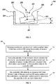
Figure 5 is an exemplary method for operating the cable handling system, in accordance with the present disclosure. - The skilled reader will recognise that one or more features of one aspect or embodiment of the present disclosure may be combined with one or more features of any other aspect or embodiment of the present disclosure unless the immediate context teaches otherwise.
- An example apparatus and method in accordance with the present disclosure will now be described with reference first to
Figures 1 and2 in which alongwall mining machine 100 is shown. Thelongwall mining machine 100 may be operated within anunderground mine 102 , as shown. Thelongwall mining machine 100 may be used to mine materials, such as coal. Nevertheless, aspects of the present disclosure may be applied to other environments, and may not be limited to the environment set forth in the following description and/or drawings. Thelongwall mining machine 100 may include aface conveyor 108 , ashearer 110 , and acable handling system 112. - The
face conveyor 108 may be an armoured face conveyor, and may be disposed and extended along a longwall face or amine face 116 of theunderground mine 102. For example, theface conveyor 108 may extend between amain gate end 120 and a tail gate end 122 (seeFigure 2 ) of theunderground mine 102. Theface conveyor 108 may include multiple face conveyor segments, referred to aspans 130.Adjacent pans 130 may be coupled to one another, and multiple interconnectedpans 130 may define apan line 138 of thelongwall mining machine 100. Thepan line 138 may be arranged in-between two stations, which may respectively accommodate sprockets and similar arrangements to help redirect anendless conveyor chain 146 of theface conveyor 108 along a cyclical path, as is commonly found in conveyor mechanisms. In that manner, theface conveyor 108 is able to transport material extracted and dropped from themine face 116 to a suitable location. An operation of theendless conveyor chain 146 may be powered by one or more drives (commonly referred to as a main drive and/or an auxiliary drive) (not shown). Theface conveyor 108 may include aguide rail 150 defined along a length, L, (seeFigure 2 ) of thepan line 138. Theguide rail 150 may facilitate a movement of theshearer 110 along thepan line 138. - The
shearer 110 may be configured to shear material, such as coal, as already noted above, from themine face 116. To this end, theshearer 110 may be guided on theguide rail 150, and, accordingly, may be traversable over and along theguide rail 150, along the length, L, of thepan line 138. During said travel, theshearer 110 may shear material from themine face 116. Theshearer 110 may include a generally elongated,main body 154, with anend 160 and a firstshearer arm assembly 162 that is coupled and moveable relative to theend 160. Theshearer 110 may include a similarly arranged, second arm assembly (not shown), which may be coupled and movable to an opposite end (not shown) of themain body 154. The firstshearer arm assembly 162 may include a cuttingdrum 168 that may be moved to engage themine face 116, and/or may be rotated about an axis upon engagement with themine face 116. In that manner, the cuttingdrum 168 may help shear and extract material from themine face 116. A similar cutting drum (not shown) may be provided on the second arm assembly. - For enabling an effective operation of the
shearer 110 and to perform one or more of the aforementioned shearer functions, such as of moving along thepan line 138, operating the cutting drums (e.g., cutting drum 168), shearing the material from themine face 116, etc., services such as power, plumbing, and the like, need to be provided to theshearer 110. Thecable handling system 112 facilitates the supply of such services to theshearer 110. - The
cable handling system 112, as shown inFigures 2 and3 , comprises a plurality ofinterconnected trays 200, aservice line 202 that is passed through theinterconnected trays 200 to theshearer 110, a plurality ofsensor nodes 203, as shown inFigure 3 , distributed along a length of theservice line 202, a plurality oftransceivers 204 distributed along a length of thepan line 138, and acontroller 206 to control one or more aspects of thecable handling system 112. - The
interconnected trays 200 may be mounted on thepan line 138. As an example, eachtray 200 may include abase wall 210, and two upstanding,side walls Figure 4 ). Further, acavity 218 may be defined between theside walls base wall 210. Thecavity 218 may have a longitudinal axis, for example parallel to theside walls tray 200 may be coupled or arranged (e.g., integrally) with onepan 130, and when eachpan 130 is assembled with theother pan 130 to form and define thepan line 138, onetray 200 may lie in registration with anadjacent tray 200. In so doing, the cavities (such as cavity 218) of eachtray 200 may combinedly define aservice trough 226 along the length, L, of thepan line 138, within which theservice line 202 may be freely disposed. In that manner, theinterconnected trays 200 are adapted to receive, accommodate, and provide passage for theservice line 202, therethrough. Further, theservice trough 226 may follow a profile of the pan line 138 - this means that as a profile of thepan line 138 within theunderground mine 102 may follow the undulations, curves, bends, highs, and lows of the profile of theunderground mine 102, so may the cumulative arrangement of the interconnected trays 200 (i.e., the profile of the service trough 226) define and follow the same profile as that of thepan line 138. - The
service line 202 may be configured to carry one or more supplies to theshearer 110 for facilitating shearer operation. For example, theservice line 202 may include a bretby type cable handler (or simply a cable handler 230) that may be disposed within and through theservice trough 226, and which may in turn hold and/or facilitate passage and routing for electrical cables, fluid lines, data and communication lines, and the like, therethrough. As an example, said electrical cables, fluid lines, data, communication lines, and the like, may extend from a source (not shown) to theshearer 110 for facilitating shearer operation. In some cases, thecable handler 230 may be fixedly coupled to themain body 154 of theshearer 110 at one end (or at a first end 232), and may be fixedly coupled to a midway region (such as to a sub-frame 234) of the pan line 138 (seeFigure 2 ), at another end (or at a second end 236). - The
shearer 110 may include atow bracket 246, and thefirst end 232 of thecable handler 230 may be operably coupled to thetow bracket 246. In so doing, theshearer 110 may receive the various inputs (from the source) required for performing the shearer operation along themine face 116 via a connection defined by thetow bracket 246. Further, owing to shearer movement, thecable handler 230 may be moveable as well. In one example, portions of thecable handler 230 may be folded and stacked layer-by-layer, one over the other, multiple times during shearer operations. To accommodate such bends and folds, thecable handler 230 may be built to generally flex along its length. - The plurality of
sensor nodes 203 are distributed along a length of theservice line 202.Sensor nodes 203 may be distributed along a length of theservice line 202 that consists of a whole of the length of theservice line 202 or only along one or more portions of theservice line 202. - The
sensor nodes 203 may be mounted on or within theservice line 202. For example, thesensor nodes 203 may be mounted on or within thecable handler 230. - The
sensor nodes 203 may be evenly distributed at regular intervals along the length of thecable handler 230, for example every 1, 2, 3...n metres, etc. Alternatively, thesensor nodes 203 may be arranged at irregular intervals. Where thecable handler 230 comprises a plurality of segments that are interconnected and configured to flex relative to one another, thesensor nodes 203 may be distributed among the segments. For example, each segment, or each 2nd, 3rd, 4th...n th segment, may be provided with asensor node 203. - The
sensor nodes 203 are suitable for sensing orientation, acceleration and/or position data. Eachsensor node 203 may comprise an accelerometer or inclinometer or similar sensor. - Each accelerometer or inclinometer or similar sensor may, for example, be a one-axis, two-axis or three-axis sensor. For example, the accelerometer or inclinometer may be a three-axis accelerometer or inclinometer that can measure accelerations or inclinations in the X-, Y- and Z-axis.
- The orientation of the sensor in the
cable handler 230 may be chosen as desired. For example, the sensor may be orientated such that any of the axes of the accelerometer or inclinometer are aligned with the longitudinal axis of thecavity 218 of thepan line 138. - In one example each
sensor node 203 comprises a MEMS accelerometer, for example a three-axis MEMS accelerometer. - Each
sensor node 203 may comprise more than one sensor. Multiple sensors may be provided for redundancy and/or for improving the signal-to-noise ratio of the sensed data. - Each
sensor node 203 may comprise a processor for performing one or more processing steps on the orientation, acceleration and/or position data before the orientation, acceleration and/or position data is transmitted to the plurality oftransceivers 204. - Each
sensor node 203 may comprise a transmitter or transmitter module for transmitting data to the plurality oftransceivers 204. The data transmitted may be raw sensed data or processed sensed data. The transmitter or transmitter module may be a wireless transmitter. For example, the transmitter or transmitter module may utilise Bluetooth, Bluetooth LE, WiFi, Near Field Communications (NFC), Infra-red (IR), 5G, LTE, UMTS, EDGE, GPRS, GSM, or any other form of RF based data communications. - Optionally, each
sensor node 203 may comprise a receiver or receiver module for receiving data fromother sensor nodes 203 and/or the plurality oftransceivers 204. The data received may be, for example, signals from thetransceivers 204 instructing thesensor node 203 to wake up and transmit data, data fromother sensor nodes 203 for onward transmission, network data link layer signals, etc.. The receiver or receiver module may be a wireless receiver. For example, the receiver may utilise Bluetooth, Bluetooth LE, WiFi, Near Field Communications (NFC), Infra-red (IR), 5G, LTE, UMTS, EDGE, GPRS, GSM, or any other form of RF based data communications. - Each
sensor node 203 may comprise a power source. The power source may be a wired connection, for example running along thecable handler 230, for supplying power from a remote source. The power source may be a local energy store, for example a battery, located in or in proximity to thesensor node 203. The battery may be a rechargeable or non-rechargeable battery. The power source may be an energy harvester. In one example, the energy harvester may generate energy for thesensor node 203 from vibrations generated during operation of thelongwall mining machine 100. In another example, the energy harvester may generate energy from EM induction, for example by inductive coupling with an electrical line of theservice line 202. - Each
sensor node 203 may comprise a capacitor for temporary storage of energy. - Each
sensor node 203 may comprise a low-power sensor. Eachsensor node 203 may comprise programming to control when a low-power mode of thesensor node 203 is activated. The programming may comprise, for example, software running on a computing resource. The computing resource may comprise a part of thesensor node 203. The computing resource may comprise, for example, a microprocessor. - The components of each
sensor node 203 may, for example, be integrated into a sensor unit. Each sensor unit may, for example, comprise a single discrete physical package. Each sensor unit may comprise a printed circuit board, or the like, for supporting and interconnecting the components of thesensor node 203, e.g. the processor, the transmitter/transmitter module, the receiver/receiver module, the power source, memory, etc. Each sensor unit may be mounted on or within theservice line 202. For example, the sensor units may be mounted on or within thecable handler 230. - Each
sensor node 203 may be configured to detect orientation, acceleration and/or position in one axis or multiple axes. For the purposes of understanding operation of thesensor nodes 203 in the present disclosure a 3-dimensional co-ordinatesystem 180, as marked inFigure 1 , is explicitly referenced. The 3-dimensional co-ordinatesystem 180 includes an X-axis, a Y-axis, and a Z-axis. It may be noted that the Z-axis is a vertical axis (i.e., defined along an elevation) of theshearer 110 ; the X-axis is a horizontal axis (i.e., defined along the length, L, of pan line 138), and is perpendicular to the Z-axis; the Y-axis is perpendicular to both the X-axis and the Z-axis and may pass through a point of intersection of the X-axis and the Z-axis. For the purposes of the present disclosure, a yaw may mean a tilting/rotation of the sensor node 203 (and, for example, its associated portion of the cable handler 230) about the Z-axis; a roll may mean a tilting/rotation of the sensor node 203 (and, for example, its associated portion of the cable handler 230) about the X-axis; and a pitch may mean a tilting/rotation of the sensor node 203 (and, for example, its associated portion of the cable handler 230) about the Y-axis. The X-axis may be coincident with the longitudinal axis of thecavity 218 of thepan line 138 and for example parallel to theside walls - The plurality of
transceivers 204 are distributed along a length of thepan line 138. Thetransceivers 204 may be spatially separate from thepan line 138. For example, thetransceivers 204 may be arranged above thepan line 138. Thetransceivers 204 may be mounted 5m to 10m above thepan line 138. Thetransceivers 204 may be mounted to be stationary in use. In one example, thetransceivers 204 may be supported from aroof support 117 extending along themine face 116. - The
transceivers 204 may be evenly distributed at regular intervals along the length of thepan line 138, for example every 5, 10, 15, 20...n metres, etc. Alternatively, thetransceivers 204 may be arranged at irregular intervals. The plurality oftransceivers 204 may be arranged linearly along thepan line 138. A path of the plurality oftransceivers 204 may follow the path of thepan line 138. - The plurality of
transceivers 204 may have a reception field 208 (e.g. the combined coverage of thetransceivers 204 in combination) covering a whole of the length L of thepan line 138. Thereception field 208 of neighbouringtransceivers 204 may overlap, for example by at least 1m, 2m, 3m, 4m or more. Eachtransceiver 204 may have a transmission/reception range of greater than 5m, optionally greater than 10m, optionally greater than 12m. - The plurality of
transceivers 204 are suitable for receiving orientation, acceleration and/or position data from the plurality ofsensor nodes 203 and transmitting the orientation, acceleration and/or position data to thecontroller 206. Thecontroller 206, or a part of thecontroller 206, may be provided remote from thetransceivers 204. Thecontroller 206, or a part of thecontroller 206, may be integrated with thetransceivers 204. - Each
transceiver 204 may comprise a receiver or receiver module for receiving the orientation, acceleration and/or position data from the plurality ofsensor nodes 203 wirelessly. For example, eachtransceiver 204 may utilise Bluetooth, Bluetooth LE, WiFi, Near Field Communications (NFC), Infra-red (IR), 5G, LTE, UMTS, EDGE, GPRS, GSM, or any other form of RF based data communications to receive data from the plurality ofsensor nodes 203. In one example, eachtransceiver 204 comprises a Bluetooth LE node/bridge. - Each
transceiver 204 may comprise (for example as part of the receiver or receiver module) an antenna, which may be a directional antenna, for receiving the orientation, acceleration and/or position data from the plurality ofsensor nodes 203. - The plurality of
transceivers 204 may be interconnected. The plurality oftransceivers 204 may be networked together. Eachtransceiver 204 may comprise a network node. For example, the network may be a Local Area Network (LAN) or a Controller Area Network (CAN). Any suitable network topology may be used, for example bus, ring, star, mesh, tree, hybrid topologies etc. Any suitable connection means may be used. The network may be a wired or wireless network. The network may utilise serial or parallel buses. The network may utilise a wired connection, e.g. Ethernet, or a wireless connection, e.g. Bluetooth, Bluetooth LE, WiFi, Near Field Communications (NFC), Infra-red (IR), 5G, LTE, UMTS, EDGE, GPRS, GSM, or any other form of RF based data communications. - Each
transceiver 204 may comprise a processor for performing one or more processing steps on the orientation, acceleration and/or position data before the orientation, acceleration and/or position data is transmitted to thecontroller 206. Additionally or alternatively, one or more processors of the transceiver may comprise a part or a whole of thecontroller 206. - Each
transceiver 204 may comprise a transmitter or transmitter module for transmitting data to the controller 206 (either directly or via one or more other transceivers 204). The transmitter or transmitter module may be a wireless transmitter. For example, eachtransceiver 204 may utilise Bluetooth, Bluetooth LE, WiFi, Near Field Communications (NFC), Infra-red (IR), 5G, LTE, UMTS, EDGE, GPRS, GSM, or any other form of RF based data communications to transmit data. Additionally or alternatively, thetransceivers 204 may transmit data to thecontroller 206 via a wired connection, e.g. via Ethernet. Additionally or alternatively, where thetransceiver 204 comprises a whole or a part of thecontroller 206, the transmitter or transmitter module may be a means for transmitting the data internally within thetransceiver 204, for example from the receiver or receiver module to one or more processors of thetransceiver 204 that form a whole or a part of thecontroller 206. Such an internal transmission within thetransceiver 204 may be a wired or wireless transmission. - Each
transceiver 204 may comprise a power source. The power source may be a wired connection, for example running along theroof support 117 extending along themine face 116 for supplying power from a remote source. - The
controller 206 may reside in one location and comprise essentially one unit, for example in the form of a discrete machine such as a PC or workstation. The unit may, for example, be located remote from theshearer 110 and may be located remote from thelongwall mining machine 100. - Alternatively, the
controller 206 may comprise a plurality of control components that work together to carry out the functions of thecontroller 206. The control components may be distributed spatially. Each control component may carry out one or more functions of thecontroller 206. The control components may be arranged locally, for example as part of a LAN or CAN. Alternatively, the control components may be arranged widely, for example as part of a WLAN. The control components may comprise remote computing resources. The control components may comprise cloud computing resources that are interconnected via a public network such as the Internet. The control components may include, comprise or consist of components, e.g. processing resources, that form part of thetransceivers 204 and/or thesensor nodes 203. - The
controller 206 may be communicably coupled to each of plurality oftransceivers 204, directly or indirectly. Signals from thetransceivers 204 may be relayed via arelay 207 that may in wired or wireless communication with thetransceivers 204 and thecontroller 206. Thecontroller 206 may be able to receive the orientation, acceleration and/or position data (raw or processed) originating from the plurality ofsensor nodes 203. For example, thecontroller 206 may receive data pertaining to one or more of the pitch, roll, and yaw, of each of thesensor nodes 203. - The
controller 206 may be able to detect an actual or imminent failure mode of theservice line 202 using analysis of the orientation, acceleration and/or position data from the plurality of thesensor nodes 203. The failure mode may comprise, for example, one or more of a dislodging of theservice line 202 from the plurality ofinterconnected trays 200, or an adverse bending of theservice line 202. - The detection of an actual or imminent failure mode of the
service line 202 may be performed remote from theservice line 202, e.g. at a unit, for example in the form of a discrete machine such as a PC or workstation, located remote from theservice line 202. - Alternatively, the detection of an actual or imminent failure mode of the
service line 202 may be performed locally, for example by one or more control components of thecontroller 206 that form part of thetransceivers 204 and/or thesensor nodes 203. - The
controller 206 may be able to transfer the result of such detection to a user, operator, supervisor, and the like, stationed either in situ or remote to thelongwall mining machine 100. For example, via a visual and/or audible alarm that may be used for raising an alert. In one example, thecable handling system 112 may include anoutput device 272 by which thecontroller 206 may notify alerts. For example, theoutput device 272 may be coupled to or may include an audible means, a visual means, or a combined audio-visual means to alert one or more workers in situ, such as the ones stationed in the vicinity of theservice line 202, or one or more remotely managing machine operators and supervisors. In one example, theoutput device 272 is an operator/supervisor workstation or a portable device by which an operator may readily be able to gather the working of thecable handling system 112. - The
controller 206 may detect an actual or imminent failure mode of theservice line 202 by analysing the orientation, acceleration and/or position data from the plurality of thesensor nodes 203, and in particular, by analysing data received frommultiple sensor nodes 203. The analysis may comprise comparing the orientation, acceleration and/or position data from a first subset of the plurality of thesensor nodes 203 with the orientation, acceleration and/or position data from a second subset of the plurality of thesensor nodes 203. - The analysis may comprise detecting the relative movement of one or more of the
sensor nodes 203 relative to one or moreother sensor nodes 203. Additionally or alternatively, the analysis may comprise detecting the absolute movement of one or more of thesensor nodes 203. For example, the analysis may comprise determining an absolute orientation and/or an absolute position (relative to an external fixed frame of reference) of at least a subset of the plurality of thesensor nodes 203. - The
controller 206 may be connected, for example wirelessly, to the longwall mining machine's electronic control module (ECM) (not shown) to enable thecontroller 206 to shut down operation of thelongwall mining machine 100 on detection of an actual or imminent failure mode of theservice line 202. - During operation, it may be assumed that initially the
service line 202 is disposed generally flat within theinterconnected trays 200 and defines a single layer from thesub-frame 234 to themain gate end 120, for example, when theshearer 110 has moved to the farthest extents of the pan line 138 (i.e., all the way to an end stop position defined proximate to the main gate end 120). At such a shearer position, theservice line 202 may form a single layer of stack within theinterconnected trays 200. - As the
shearer 110 leaves themain gate end 120, theservice line 202 may invert direction, thereby creating a turn in theservice line 202. As theshearer 110 moves further, the turned service line portion may move as well, laying and traversing atop a first (underlying) layer of theservice line 202, and may accordingly define a second layer in thestack 270 of theservice line 202. The created turn may follow behind theshearer 110. Due to the typical cutting sequence in thelongwall mining machine 100, theshearer 110 may often change its direction before completing a shear cycle, and may repeatedly travel back-and-forth across themine face 116. In some cases, accordingly, as theshearer 110 direction may again be reversed, theservice line 202 may again create further turns, and, accordingly, on every such turn, theservice line 202 may increment the count of the layer forming thestack 270. - The aforementioned operational aspect describes a general working of the
shearer 110 along thepan line 138. During such operation of theshearer 110, and in light of the profile of the pan line 138 (that may include bends, curves, etc.), and a typical pattern of shearer operation as discussed above, it may become possible for theservice line 202 to suffer a failure mode, for example a dislodgment and escape of theservice line 202 from theinterconnected trays 200. Certain aspects of the present disclosure are set to detect an actual or imminent failure mode. - Referring to
Figure 5 , amethod 700 for detecting an actual or imminent failure mode comprise in afirst step 701 sensing orientation, acceleration and/or position data of theservice line 202 using the plurality ofsensor nodes 203. - In a
second step 702 the plurality oftransceivers 204 are used to receive the orientation, acceleration and/or position data from the plurality ofsensor nodes 203 and to transmit the orientation, acceleration and/or position data to thecontroller 206. As noted above, thecontroller 206 may be, for example, a discrete machine such as a PC or workstation, located remote from theservice line 202. In such a case the transmission of the orientation, acceleration and/or position data may comprise a transmission, e.g. by wired or wireless means, from the plurality oftransceivers 204 to the remotely-locatedcontroller 206. Alternatively, also as noted above, thecontroller 206, or a part of thecontroller 206, may form part of thetransceivers 204 and/orsensor nodes 203. In such a case the transmission of the orientation, acceleration and/or position data may comprise an internal transmission within the one ormore transceivers 204 or within the one ormore sensor nodes 203 or between thesensor nodes 203 and thetransceivers 204. - In a
third step 703 thecontroller 206 detects an actual or imminent failure mode of theservice line 202 using analysis of the orientation, acceleration and/or position data from the plurality of thesensor nodes 203. - The skilled person will understand from the present disclosure that the function of the
controller 206 may be performed by one or more units that may be distributed spatially and one or more functions of thecontroller 206 may be performed by one or more of: thesensor nodes 203, thetransceivers 204 and computing resources that located remote from theshearer 110 and may be located remote from the entirelongwall mining machine 100. - In the
second step 702, at any point in time, orientation, acceleration and/or position data from any of the plurality ofsensor nodes 203 may be received by the plurality oftransceivers 204 due to the reception field of thetransceivers 204 covering the whole length, L, of thepan line 138. Consequently, thecable handling system 112 may be enabled to detect an actual or imminent failure mode at any point along the length, L, of theservice line 202 at all times. - The orientation, acceleration and/or position data from the plurality of
sensor nodes 203 may be transmitted to thetransceivers 204 on a continuous or intermittent basis. For example, thesensor nodes 203 may be configured to transmit data at fixed time intervals. Thesensor nodes 203 may be configured to enter a low-energy state inbetween transmissions. Thesensor nodes 203 may be configured to sense orientation, acceleration and/or position data at a higher frequency than the frequency of transmission of the data to thetransceivers 204. In this case thesensor nodes 203 may comprise memory for storing and collating data for transmitting at a later time point. - During an actual or imminent failure mode of the service line 202 a portion of the
service line 202, and in particular a portion of thecable handler 230, may undergo an unexpected event that may be detected by thecontroller 206 using the orientation, acceleration and/or position data from the plurality ofsensor nodes 203. - The
controller 206 may detect an unexpected event using the absolute orientation, acceleration and/or position of thesensor nodes 203. Additionally, or alternatively, thecontroller 206 may detect an unexpected event using the orientation, acceleration and/or position of thesensor nodes 203 relative to each other. - The
controller 206 may detect the unexpected event without needing to have knowledge of the overall profile of thepan line 138. Consequently, there may be no requirement for thecable handling system 112 to being programmed with, or to plot, the profile of thepan line 138. - In one example, the unexpected event may comprise a movement in a transverse direction, i.e. in the Y-axis, or comprising a movement having at least a component in the transverse direction. Referring to the example figure of
Figure 4 , a transverse movement in that example would be a movement to the left or right in the orientation as shown. A sudden movement or acceleration having at least a component in the Y-axis above a threshold amount may be considered an unexpected event since in practice the curves and bends of thepan line 138 in the plane of the Y-axis have a relatively large radius of curvature, i.e. sharp bends and curves are typically avoided. - For example, a sudden movement or acceleration having at least a component in the Y-axis above a threshold amount may be indicative that the
service line 202 has moved past or started to move past (i.e. over) one of the side walls, 212, 214. Thecontroller 206 may determine that the degree of the movement in the Y-axis is unexpected by comparing the absolute magnitude of the movement or acceleration to a pre-determined threshold. Alternatively, thecontroller 206 may determine that the degree of the movement in the Y-axis is unexpected by comparing the orientation, acceleration and/or position of thesensor nodes 203 relative to each other. For example, if a first subset of thesensor nodes 203 is detected as moving significantly (e.g. above a threshold mount) in the Y-axis compared to a second subset ofsensor nodes 203 that are proximate the first subset this may be indicative of a localised actual or imminent failure of theservice line 202. For example this may be indicative of an adverse bend developing in theservice line 202 or a portion of theservice line 202 being dislodged from theinterconnected trays 200. - In another example the unexpected event may comprise or consist of a rolling movement or acceleration about the X-axis as shown in
Figure 4 such that a portion of thecable handler 230 is tilted at an angle A to thebase wall 210 of theinterconnected trays 200. - Such a movement or acceleration may be indicative that the
service line 202 has started to fall out of theinterconnected trays 200 creating a twisting or warping shape to a portion of thecable handler 230. Thecontroller 206 may determine that the degree of the rolling movement or acceleration about the X-axis is unexpected by comparing the absolute magnitude of the movement or acceleration to a pre-determined threshold. Alternatively, thecontroller 206 may determine that the degree of the rolling movement about the X-axis is unexpected by comparing the orientation, acceleration and/or position of thesensor nodes 203 relative to each other. For example, if a first subset of thesensor nodes 203 is detected as moving significantly (e.g. above a threshold mount) about the X-axis compared to a second subset ofsensor nodes 203 that are proximate the first subset this may be indicative of a localised actual or imminent failure of theservice line 202. For example this may be indicative of a portion of theservice line 202 being dislodged from theinterconnected trays 200 or theservice line 202 encountering an obstruction (e.g. rock debris) in theinterconnected trays 200. - In the event that the
controller 206 detects that there exists an actual or imminent failure mode of theservice line 202 it may issue an alert, for example via theoutput device 272. Additionally or alternatively, thecontroller 206 may instigate a shut down of the operation of thelongwall mining machine 100 by communicating with the ECM of thelongwall mining machine 100. The shut down may be automatic (without user intervention). Additionally or alternatively, thecontroller 206 may raise a system alert when an actual or imminent failure mode of theservice line 202 is detected. The system alert may be provided to an operator or to another part of the control system for appropriate action to be taken. - It will be apparent to those skilled in the art that various modifications and variations can be made to the method and system of the present disclosure without departing from the scope of the disclosure. Other embodiments will be apparent to those skilled in the art from consideration of the specification and practice of the method and system disclosed herein. It is intended that the specification and examples be considered as exemplary only, with a true scope of the disclosure being indicated by the following claims and their equivalent.
Claims (15)
- A method of operating a cable handling system of a longwall mining machine having a shearer movable along a pan line to mine material along a mine face, the cable handling system including:i) a service line configured to carry one or more supply lines to the shearer for facilitating shearer operation,ii) a plurality of interconnected trays to accommodate the service line,iii) a plurality of sensor nodes distributed along a length of the service line,iv) a plurality of transceivers distributed along a length of the pan line, andv) a controller;the method comprising:a) sensing and transmitting orientation, acceleration and/or position data of the service line using the plurality of sensor nodes,b) using the plurality of transceivers to receive the orientation, acceleration and/or position data from the plurality of sensor nodes and to transmit the orientation, acceleration and/or position data to the controller, andc) detecting, by the controller, an actual or imminent failure mode of the service line using analysis of the orientation, acceleration and/or position data from the plurality of the sensor nodes.
- The method of claim 1, wherein the plurality of transceivers have a reception field covering a whole of the length of the pan line such that, in step b), at any point in time orientation, acceleration and/or position data from any of the plurality of sensor nodes is receivable by the plurality of transceivers.
- The method of claim 1 or claim 2, wherein, in step c), analysis of the orientation, acceleration and/or position data from the plurality of the sensor nodes comprises comparing the orientation, acceleration and/or position data from a first subset of the plurality of the sensor nodes with the orientation, acceleration and/or position data from a second subset of the plurality of the sensor nodes.
- The method of any preceding claim, wherein, in step c), analysis of the orientation, acceleration and/or position data from the plurality of the sensor nodes comprises determining an absolute orientation and/or an absolute position of at least a subset of the plurality of the sensor nodes.
- The method of any preceding claim, wherein the failure mode comprises one or more of:dislodging of the service line from the plurality of interconnected trays; oradverse bending of the service line.
- The method of any preceding claim, wherein each of the plurality of interconnected trays comprises a base wall, a first side wall and a second side wall together defining a cavity for receiving a portion of the service line, the cavity having a longitudinal axis; and the orientation, acceleration and/or position data of the service line comprises data for detecting or inferring at least a component of movement of the service line in a transverse direction that is perpendicular to the longitudinal axis, the first side wall and the second side wall.
- The method of any preceding claim, wherein the plurality of transceivers are interconnected to form a network, optionally a mesh network.
- The method of any preceding claim, further comprising step d) raising an alert and/or automatically stopping the longwall mining machine when an actual or imminent failure mode of the service line is detected.
- A cable handling system for a longwall mining machine, the longwall mining machine including a shearer configured to move along a pan line to mine material along a mine face, the cable handling system comprising:i) a service line configured to carry one or more supply lines to the shearer for facilitating shearer operation,ii) a plurality of interconnected trays to accommodate the service line,iii) a plurality of sensor nodes distributed along a length of the service line,iv) a plurality of transceivers distributed along a length of the pan line, andv) a controller configured to:a) receive orientation, acceleration and/or position data of the service line that originates from the plurality of sensor nodes, is transmitted to the plurality of transceivers, and is then transmitted to the controller by the plurality of transceivers, andb) analyse the orientation, acceleration and/or position data to detect an actual or imminent failure mode of the service line.
- The cable handling system of claim 9, wherein the plurality of transceivers are distributed along a whole of the length of the pan line such that a reception field of the plurality of transceivers enables, at any point in time, orientation, acceleration and/or position data from any of the plurality of sensor nodes to be receivable by the plurality of transceivers irrespective of a degree of extension of retraction of the service line along the pan line.
- The cable handling system of claim 9 or claim 10, wherein the plurality of transceivers are interconnected to form a network, optionally a mesh network.
- The cable handling system of any one of claims 9 to 11, wherein the plurality of transceivers are arranged above the pan line; and are optionally supported from a roof support extending along the mine face.
- The cable handling system of any one of claims 9 to 12, wherein the controller is configured to compare the orientation, acceleration and/or position data from a first subset of the plurality of the sensor nodes with the orientation, acceleration and/or position data from a second subset of the plurality of the sensor nodes; and optionally
wherein the controller is configured to determine an absolute orientation and/or an absolute position of at least a subset of the plurality of the sensor nodes. - The cable handling system of any one of claims 9 to 13, wherein the controller is configured to detect a failure mode that comprises one or more of:dislodging of the service line from the plurality of interconnected trays; oradverse bending of the service line.
- The cable handling system of any one of claims 9 to 14, wherein each of the plurality of interconnected trays comprises a base wall, a first side wall and a second side wall together defining a cavity for receiving a portion of the service line, the cavity having a longitudinal axis; and the orientation, acceleration and/or position data of the service line comprises data for detecting or inferring at least a component of movement of the service line in a transverse direction that is perpendicular to the longitudinal axis, the first side wall and the second side wall; and optionally
the cable handling system further comprising a visual and/or audible alarm for raising an alert; and/or the controller is configured to automatically stop the longwall mining machine when an actual or imminent failure mode of the service line is detected; and/or the controller is configured to raise a system alert when an actual or imminent failure mode of the service line is detected.
Applications Claiming Priority (1)
| Application Number | Priority Date | Filing Date | Title |
|---|---|---|---|
| GB2108671.5A GB2607938B (en) | 2021-06-17 | 2021-06-17 | Cable handling system for longwall mining machines |
Publications (2)
| Publication Number | Publication Date |
|---|---|
| EP4105436A1 true EP4105436A1 (en) | 2022-12-21 |
| EP4105436B1 EP4105436B1 (en) | 2024-08-21 |
Family
ID=77050455
Family Applications (1)
| Application Number | Title | Priority Date | Filing Date |
|---|---|---|---|
| EP22174290.1A Active EP4105436B1 (en) | 2021-06-17 | 2022-05-19 | Cable handling system for longwall mining machines |
Country Status (5)
| Country | Link |
|---|---|
| US (1) | US11927097B2 (en) |
| EP (1) | EP4105436B1 (en) |
| AU (1) | AU2022203511A1 (en) |
| GB (1) | GB2607938B (en) |
| PL (1) | PL4105436T3 (en) |
Families Citing this family (2)
| Publication number | Priority date | Publication date | Assignee | Title |
|---|---|---|---|---|
| CN119507911A (en) * | 2024-11-20 | 2025-02-25 | 江西鑫通机械制造有限公司 | A mining trolley distributed control method, system, device and storage medium |
| CN121345537B (en) * | 2025-12-08 | 2026-04-17 | 华北科技学院(中国煤矿安全技术培训中心) | A delamination grouting device based on water-retaining mining |
Citations (1)
| Publication number | Priority date | Publication date | Assignee | Title |
|---|---|---|---|---|
| US20200024943A1 (en) | 2018-07-23 | 2020-01-23 | Caterpillar Global Mining Europe Gmbh | Cable handling system for longwall mining machines |
Family Cites Families (10)
| Publication number | Priority date | Publication date | Assignee | Title |
|---|---|---|---|---|
| GB2129032B (en) * | 1982-10-21 | 1986-08-28 | Dobson Park Ind | Monitoring apparatus |
| DE20305309U1 (en) * | 2003-04-01 | 2004-05-13 | Dbt Automation Gmbh | Longwall control |
| WO2004090375A1 (en) * | 2003-04-04 | 2004-10-21 | Igus Gmbh | Monitoring system for the operation of at least one energy drag chain |
| US7793442B2 (en) | 2008-04-29 | 2010-09-14 | Caterpillar Inc | Avoidance system for locating electric cables |
| DE202014100540U1 (en) | 2014-02-07 | 2014-03-20 | Igus Gmbh | Energy guiding chain and monitoring system for protection against cable breakage |
| CN203891880U (en) | 2014-03-04 | 2014-10-22 | 天地上海采掘装备科技有限公司 | Cable towing device for coal mining machine |
| CN105784241B (en) | 2016-03-07 | 2018-04-13 | 中国矿业大学 | A kind of scraper conveyer chain tension force evaluation method |
| DE202016107317U1 (en) * | 2016-12-23 | 2017-03-27 | Igus Gmbh | Systems for monitoring the operation of an energy chain |
| GB2576172A (en) | 2018-08-07 | 2020-02-12 | Caterpillar Global Mining Gmbh | Shearing system for longwall mining |
| CN110017774A (en) | 2019-05-14 | 2019-07-16 | 天地科技股份有限公司上海分公司 | 3 d pose detection cable formula sensor |
-
2021
- 2021-06-17 GB GB2108671.5A patent/GB2607938B/en active Active
-
2022
- 2022-05-19 EP EP22174290.1A patent/EP4105436B1/en active Active
- 2022-05-19 PL PL22174290.1T patent/PL4105436T3/en unknown
- 2022-05-24 AU AU2022203511A patent/AU2022203511A1/en active Pending
- 2022-06-17 US US17/842,942 patent/US11927097B2/en active Active
Patent Citations (1)
| Publication number | Priority date | Publication date | Assignee | Title |
|---|---|---|---|---|
| US20200024943A1 (en) | 2018-07-23 | 2020-01-23 | Caterpillar Global Mining Europe Gmbh | Cable handling system for longwall mining machines |
Non-Patent Citations (1)
| Title |
|---|
| MUDULI LALATENDU ET AL: "A novel wireless sensor network deployment scheme for environmental monitoring in longwall coal mines", PROCESS SAFETY AND ENVIRONMENTAL PROTECTION, INSTITUTION OF CHEMICAL ENGINEERS, RUGBY, GB, vol. 109, 10 May 2017 (2017-05-10), pages 564 - 576, XP085123716, ISSN: 0957-5820, DOI: 10.1016/J.PSEP.2017.04.030 * |
Also Published As
| Publication number | Publication date |
|---|---|
| AU2022203511A1 (en) | 2023-01-19 |
| GB202108671D0 (en) | 2021-08-04 |
| GB2607938A (en) | 2022-12-21 |
| US20220403738A1 (en) | 2022-12-22 |
| PL4105436T3 (en) | 2024-10-28 |
| GB2607938B (en) | 2024-01-03 |
| EP4105436B1 (en) | 2024-08-21 |
| US11927097B2 (en) | 2024-03-12 |
Similar Documents
| Publication | Publication Date | Title |
|---|---|---|
| US11927097B2 (en) | Cable handling system for longwall mining machines | |
| CN106103895B (en) | Force piece for underground mining | |
| EP2569652B1 (en) | Method and apparatus for mining vehicle safety arrangements | |
| US5667279A (en) | Apparatus and method for continuous mining | |
| AU696485B2 (en) | Apparatus and method for continuous mining | |
| KR102393157B1 (en) | System for monitoring abnormality of conveyor apparatus and method for the same | |
| US11149546B2 (en) | Cable handling system for longwall mining machines | |
| SE2130149A1 (en) | Wellbore inspection system and method for ultra-deep vertical shaft | |
| KR101889042B1 (en) | Network system for risk remote monitoring and managing of tunnel under construction | |
| WO2015107068A1 (en) | Mine vehicle and method of initiating mine work task | |
| CN102061914A (en) | Method for steering a mining machine cutter | |
| EP3094806A1 (en) | Mine vehicle and method of initiating mine work task | |
| CN106671992A (en) | Patrolling and detecting robot for coal mine fully-mechanized coal mining face | |
| CN106133274B (en) | System for controlling the travel speed of a longwall shearer | |
| CN116749183A (en) | A driving system and method for remote control of mining inspection robots | |
| AU2021201575A1 (en) | Cutting pick monitoring system and method for longwall mining system | |
| JP5491360B2 (en) | Ventilation system in underground space | |
| CN116749213A (en) | A control system and control method for a mining inspection robot | |
| Stentz et al. | Position measurement for automated mining machinery | |
| CN208267842U (en) | Can intelligent remote monitoring control coalcutter | |
| CN105179007B (en) | A kind of fully-mechanized mining working inspection running device | |
| CN113835382A (en) | Remote control system of roadheader | |
| CN117081499A (en) | Photovoltaic panel cleaning system | |
| CN211698185U (en) | Radar device for monitoring side slope of open stope | |
| AU2023360037B2 (en) | Underground development drill boom tracking system |
Legal Events
| Date | Code | Title | Description |
|---|---|---|---|
| PUAI | Public reference made under article 153(3) epc to a published international application that has entered the european phase |
Free format text: ORIGINAL CODE: 0009012 |
|
| STAA | Information on the status of an ep patent application or granted ep patent |
Free format text: STATUS: THE APPLICATION HAS BEEN PUBLISHED |
|
| AK | Designated contracting states |
Kind code of ref document: A1 Designated state(s): AL AT BE BG CH CY CZ DE DK EE ES FI FR GB GR HR HU IE IS IT LI LT LU LV MC MK MT NL NO PL PT RO RS SE SI SK SM TR |
|
| STAA | Information on the status of an ep patent application or granted ep patent |
Free format text: STATUS: REQUEST FOR EXAMINATION WAS MADE |
|
| 17P | Request for examination filed |
Effective date: 20230320 |
|
| RBV | Designated contracting states (corrected) |
Designated state(s): AL AT BE BG CH CY CZ DE DK EE ES FI FR GB GR HR HU IE IS IT LI LT LU LV MC MK MT NL NO PL PT RO RS SE SI SK SM TR |
|
| GRAP | Despatch of communication of intention to grant a patent |
Free format text: ORIGINAL CODE: EPIDOSNIGR1 |
|
| STAA | Information on the status of an ep patent application or granted ep patent |
Free format text: STATUS: GRANT OF PATENT IS INTENDED |
|
| RIC1 | Information provided on ipc code assigned before grant |
Ipc: H02G 11/00 20060101ALI20240301BHEP Ipc: E21C 27/02 20060101ALI20240301BHEP Ipc: H02G 3/04 20060101ALI20240301BHEP Ipc: E21C 35/04 20060101ALI20240301BHEP Ipc: E21C 25/06 20060101AFI20240301BHEP |
|
| INTG | Intention to grant announced |
Effective date: 20240328 |
|
| RIN1 | Information on inventor provided before grant (corrected) |
Inventor name: PADHI, LAKSHMINARAYANA Inventor name: GANESAN, MAHENDRA Inventor name: ROZARIO, WILFRED Inventor name: KIRKHOPE, EUAN Inventor name: SAIKIA, SIDDARTHA |
|
| GRAS | Grant fee paid |
Free format text: ORIGINAL CODE: EPIDOSNIGR3 |
|
| GRAA | (expected) grant |
Free format text: ORIGINAL CODE: 0009210 |
|
| STAA | Information on the status of an ep patent application or granted ep patent |
Free format text: STATUS: THE PATENT HAS BEEN GRANTED |
|
| P01 | Opt-out of the competence of the unified patent court (upc) registered |
Free format text: CASE NUMBER: APP_36931/2024 Effective date: 20240620 |
|
| AK | Designated contracting states |
Kind code of ref document: B1 Designated state(s): AL AT BE BG CH CY CZ DE DK EE ES FI FR GB GR HR HU IE IS IT LI LT LU LV MC MK MT NL NO PL PT RO RS SE SI SK SM TR |
|
| REG | Reference to a national code |
Ref country code: GB Ref legal event code: FG4D |
|
| REG | Reference to a national code |
Ref country code: CH Ref legal event code: EP |
|
| REG | Reference to a national code |
Ref country code: DE Ref legal event code: R096 Ref document number: 602022005427 Country of ref document: DE |
|
| REG | Reference to a national code |
Ref country code: IE Ref legal event code: FG4D |
|
| REG | Reference to a national code |
Ref country code: LT Ref legal event code: MG9D |
|
| REG | Reference to a national code |
Ref country code: NL Ref legal event code: MP Effective date: 20240821 |
|
| PG25 | Lapsed in a contracting state [announced via postgrant information from national office to epo] |
Ref country code: NO Free format text: LAPSE BECAUSE OF FAILURE TO SUBMIT A TRANSLATION OF THE DESCRIPTION OR TO PAY THE FEE WITHIN THE PRESCRIBED TIME-LIMIT Effective date: 20241121 |
|
| REG | Reference to a national code |
Ref country code: AT Ref legal event code: MK05 Ref document number: 1715653 Country of ref document: AT Kind code of ref document: T Effective date: 20240821 |
|
| PG25 | Lapsed in a contracting state [announced via postgrant information from national office to epo] |
Ref country code: PT Free format text: LAPSE BECAUSE OF FAILURE TO SUBMIT A TRANSLATION OF THE DESCRIPTION OR TO PAY THE FEE WITHIN THE PRESCRIBED TIME-LIMIT Effective date: 20241223 Ref country code: NL Free format text: LAPSE BECAUSE OF FAILURE TO SUBMIT A TRANSLATION OF THE DESCRIPTION OR TO PAY THE FEE WITHIN THE PRESCRIBED TIME-LIMIT Effective date: 20240821 Ref country code: GR Free format text: LAPSE BECAUSE OF FAILURE TO SUBMIT A TRANSLATION OF THE DESCRIPTION OR TO PAY THE FEE WITHIN THE PRESCRIBED TIME-LIMIT Effective date: 20241122 Ref country code: FI Free format text: LAPSE BECAUSE OF FAILURE TO SUBMIT A TRANSLATION OF THE DESCRIPTION OR TO PAY THE FEE WITHIN THE PRESCRIBED TIME-LIMIT Effective date: 20240821 |
|
| PG25 | Lapsed in a contracting state [announced via postgrant information from national office to epo] |
Ref country code: BG Free format text: LAPSE BECAUSE OF FAILURE TO SUBMIT A TRANSLATION OF THE DESCRIPTION OR TO PAY THE FEE WITHIN THE PRESCRIBED TIME-LIMIT Effective date: 20240821 |
|
| PG25 | Lapsed in a contracting state [announced via postgrant information from national office to epo] |
Ref country code: LV Free format text: LAPSE BECAUSE OF FAILURE TO SUBMIT A TRANSLATION OF THE DESCRIPTION OR TO PAY THE FEE WITHIN THE PRESCRIBED TIME-LIMIT Effective date: 20240821 |
|
| PG25 | Lapsed in a contracting state [announced via postgrant information from national office to epo] |
Ref country code: IS Free format text: LAPSE BECAUSE OF FAILURE TO SUBMIT A TRANSLATION OF THE DESCRIPTION OR TO PAY THE FEE WITHIN THE PRESCRIBED TIME-LIMIT Effective date: 20241221 Ref country code: AT Free format text: LAPSE BECAUSE OF FAILURE TO SUBMIT A TRANSLATION OF THE DESCRIPTION OR TO PAY THE FEE WITHIN THE PRESCRIBED TIME-LIMIT Effective date: 20240821 |
|
| PG25 | Lapsed in a contracting state [announced via postgrant information from national office to epo] |
Ref country code: HR Free format text: LAPSE BECAUSE OF FAILURE TO SUBMIT A TRANSLATION OF THE DESCRIPTION OR TO PAY THE FEE WITHIN THE PRESCRIBED TIME-LIMIT Effective date: 20240821 |
|
| PG25 | Lapsed in a contracting state [announced via postgrant information from national office to epo] |
Ref country code: ES Free format text: LAPSE BECAUSE OF FAILURE TO SUBMIT A TRANSLATION OF THE DESCRIPTION OR TO PAY THE FEE WITHIN THE PRESCRIBED TIME-LIMIT Effective date: 20240821 Ref country code: RS Free format text: LAPSE BECAUSE OF FAILURE TO SUBMIT A TRANSLATION OF THE DESCRIPTION OR TO PAY THE FEE WITHIN THE PRESCRIBED TIME-LIMIT Effective date: 20241121 |
|
| PG25 | Lapsed in a contracting state [announced via postgrant information from national office to epo] |
Ref country code: RS Free format text: LAPSE BECAUSE OF FAILURE TO SUBMIT A TRANSLATION OF THE DESCRIPTION OR TO PAY THE FEE WITHIN THE PRESCRIBED TIME-LIMIT Effective date: 20241121 Ref country code: PT Free format text: LAPSE BECAUSE OF FAILURE TO SUBMIT A TRANSLATION OF THE DESCRIPTION OR TO PAY THE FEE WITHIN THE PRESCRIBED TIME-LIMIT Effective date: 20241223 Ref country code: NO Free format text: LAPSE BECAUSE OF FAILURE TO SUBMIT A TRANSLATION OF THE DESCRIPTION OR TO PAY THE FEE WITHIN THE PRESCRIBED TIME-LIMIT Effective date: 20241121 Ref country code: NL Free format text: LAPSE BECAUSE OF FAILURE TO SUBMIT A TRANSLATION OF THE DESCRIPTION OR TO PAY THE FEE WITHIN THE PRESCRIBED TIME-LIMIT Effective date: 20240821 Ref country code: LV Free format text: LAPSE BECAUSE OF FAILURE TO SUBMIT A TRANSLATION OF THE DESCRIPTION OR TO PAY THE FEE WITHIN THE PRESCRIBED TIME-LIMIT Effective date: 20240821 Ref country code: IS Free format text: LAPSE BECAUSE OF FAILURE TO SUBMIT A TRANSLATION OF THE DESCRIPTION OR TO PAY THE FEE WITHIN THE PRESCRIBED TIME-LIMIT Effective date: 20241221 Ref country code: HR Free format text: LAPSE BECAUSE OF FAILURE TO SUBMIT A TRANSLATION OF THE DESCRIPTION OR TO PAY THE FEE WITHIN THE PRESCRIBED TIME-LIMIT Effective date: 20240821 Ref country code: GR Free format text: LAPSE BECAUSE OF FAILURE TO SUBMIT A TRANSLATION OF THE DESCRIPTION OR TO PAY THE FEE WITHIN THE PRESCRIBED TIME-LIMIT Effective date: 20241122 Ref country code: FI Free format text: LAPSE BECAUSE OF FAILURE TO SUBMIT A TRANSLATION OF THE DESCRIPTION OR TO PAY THE FEE WITHIN THE PRESCRIBED TIME-LIMIT Effective date: 20240821 Ref country code: ES Free format text: LAPSE BECAUSE OF FAILURE TO SUBMIT A TRANSLATION OF THE DESCRIPTION OR TO PAY THE FEE WITHIN THE PRESCRIBED TIME-LIMIT Effective date: 20240821 Ref country code: BG Free format text: LAPSE BECAUSE OF FAILURE TO SUBMIT A TRANSLATION OF THE DESCRIPTION OR TO PAY THE FEE WITHIN THE PRESCRIBED TIME-LIMIT Effective date: 20240821 Ref country code: AT Free format text: LAPSE BECAUSE OF FAILURE TO SUBMIT A TRANSLATION OF THE DESCRIPTION OR TO PAY THE FEE WITHIN THE PRESCRIBED TIME-LIMIT Effective date: 20240821 |
|
| PG25 | Lapsed in a contracting state [announced via postgrant information from national office to epo] |
Ref country code: DK Free format text: LAPSE BECAUSE OF FAILURE TO SUBMIT A TRANSLATION OF THE DESCRIPTION OR TO PAY THE FEE WITHIN THE PRESCRIBED TIME-LIMIT Effective date: 20240821 Ref country code: RO Free format text: LAPSE BECAUSE OF FAILURE TO SUBMIT A TRANSLATION OF THE DESCRIPTION OR TO PAY THE FEE WITHIN THE PRESCRIBED TIME-LIMIT Effective date: 20240821 Ref country code: SM Free format text: LAPSE BECAUSE OF FAILURE TO SUBMIT A TRANSLATION OF THE DESCRIPTION OR TO PAY THE FEE WITHIN THE PRESCRIBED TIME-LIMIT Effective date: 20240821 |
|
| PG25 | Lapsed in a contracting state [announced via postgrant information from national office to epo] |
Ref country code: EE Free format text: LAPSE BECAUSE OF FAILURE TO SUBMIT A TRANSLATION OF THE DESCRIPTION OR TO PAY THE FEE WITHIN THE PRESCRIBED TIME-LIMIT Effective date: 20240821 |
|
| PG25 | Lapsed in a contracting state [announced via postgrant information from national office to epo] |
Ref country code: CZ Free format text: LAPSE BECAUSE OF FAILURE TO SUBMIT A TRANSLATION OF THE DESCRIPTION OR TO PAY THE FEE WITHIN THE PRESCRIBED TIME-LIMIT Effective date: 20240821 |
|
| PG25 | Lapsed in a contracting state [announced via postgrant information from national office to epo] |
Ref country code: SK Free format text: LAPSE BECAUSE OF FAILURE TO SUBMIT A TRANSLATION OF THE DESCRIPTION OR TO PAY THE FEE WITHIN THE PRESCRIBED TIME-LIMIT Effective date: 20240821 Ref country code: IT Free format text: LAPSE BECAUSE OF FAILURE TO SUBMIT A TRANSLATION OF THE DESCRIPTION OR TO PAY THE FEE WITHIN THE PRESCRIBED TIME-LIMIT Effective date: 20240821 |
|
| REG | Reference to a national code |
Ref country code: DE Ref legal event code: R097 Ref document number: 602022005427 Country of ref document: DE |
|
| PLBE | No opposition filed within time limit |
Free format text: ORIGINAL CODE: 0009261 |
|
| STAA | Information on the status of an ep patent application or granted ep patent |
Free format text: STATUS: NO OPPOSITION FILED WITHIN TIME LIMIT |
|
| PGFP | Annual fee paid to national office [announced via postgrant information from national office to epo] |
Ref country code: PL Payment date: 20250423 Year of fee payment: 4 Ref country code: DE Payment date: 20250423 Year of fee payment: 4 |
|
| 26N | No opposition filed |
Effective date: 20250522 |
|
| PG25 | Lapsed in a contracting state [announced via postgrant information from national office to epo] |
Ref country code: SE Free format text: LAPSE BECAUSE OF FAILURE TO SUBMIT A TRANSLATION OF THE DESCRIPTION OR TO PAY THE FEE WITHIN THE PRESCRIBED TIME-LIMIT Effective date: 20240821 |
|
| REG | Reference to a national code |
Ref country code: CH Ref legal event code: H13 Free format text: ST27 STATUS EVENT CODE: U-0-0-H10-H13 (AS PROVIDED BY THE NATIONAL OFFICE) Effective date: 20251223 |
|
| PG25 | Lapsed in a contracting state [announced via postgrant information from national office to epo] |
Ref country code: LU Free format text: LAPSE BECAUSE OF NON-PAYMENT OF DUE FEES Effective date: 20250519 |
|
| PG25 | Lapsed in a contracting state [announced via postgrant information from national office to epo] |
Ref country code: CH Free format text: LAPSE BECAUSE OF NON-PAYMENT OF DUE FEES Effective date: 20250531 |
|
| REG | Reference to a national code |
Ref country code: BE Ref legal event code: MM Effective date: 20250531 |
|
| PG25 | Lapsed in a contracting state [announced via postgrant information from national office to epo] |
Ref country code: MC Free format text: LAPSE BECAUSE OF FAILURE TO SUBMIT A TRANSLATION OF THE DESCRIPTION OR TO PAY THE FEE WITHIN THE PRESCRIBED TIME-LIMIT Effective date: 20240821 |
|
| PG25 | Lapsed in a contracting state [announced via postgrant information from national office to epo] |
Ref country code: IE Free format text: LAPSE BECAUSE OF NON-PAYMENT OF DUE FEES Effective date: 20250519 |
|
| PG25 | Lapsed in a contracting state [announced via postgrant information from national office to epo] |
Ref country code: BE Free format text: LAPSE BECAUSE OF NON-PAYMENT OF DUE FEES Effective date: 20250531 |
|
| PG25 | Lapsed in a contracting state [announced via postgrant information from national office to epo] |
Ref country code: FR Free format text: LAPSE BECAUSE OF NON-PAYMENT OF DUE FEES Effective date: 20250531 |