EP4105391A1 - Surroundings sensing device for work machine - Google Patents
Surroundings sensing device for work machine Download PDFInfo
- Publication number
- EP4105391A1 EP4105391A1 EP21781724.6A EP21781724A EP4105391A1 EP 4105391 A1 EP4105391 A1 EP 4105391A1 EP 21781724 A EP21781724 A EP 21781724A EP 4105391 A1 EP4105391 A1 EP 4105391A1
- Authority
- EP
- European Patent Office
- Prior art keywords
- captured image
- working machine
- region
- boundary
- observation device
- Prior art date
- Legal status (The legal status is an assumption and is not a legal conclusion. Google has not performed a legal analysis and makes no representation as to the accuracy of the status listed.)
- Granted
Links
Images




Classifications
-
- H—ELECTRICITY
- H04—ELECTRIC COMMUNICATION TECHNIQUE
- H04N—PICTORIAL COMMUNICATION, e.g. TELEVISION
- H04N7/00—Television systems
- H04N7/18—Closed-circuit television [CCTV] systems, i.e. systems in which the video signal is not broadcast
- H04N7/181—Closed-circuit television [CCTV] systems, i.e. systems in which the video signal is not broadcast for receiving images from a plurality of remote sources
-
- E—FIXED CONSTRUCTIONS
- E02—HYDRAULIC ENGINEERING; FOUNDATIONS; SOIL SHIFTING
- E02F—DREDGING; SOIL-SHIFTING
- E02F3/00—Dredgers; Soil-shifting machines
- E02F3/04—Dredgers; Soil-shifting machines mechanically-driven
- E02F3/28—Dredgers; Soil-shifting machines mechanically-driven with digging tools mounted on a dipper- or bucket-arm, i.e. there is either one arm or a pair of arms, e.g. dippers, buckets
- E02F3/30—Dredgers; Soil-shifting machines mechanically-driven with digging tools mounted on a dipper- or bucket-arm, i.e. there is either one arm or a pair of arms, e.g. dippers, buckets with a dipper-arm pivoted on a cantilever beam, i.e. boom
- E02F3/32—Dredgers; Soil-shifting machines mechanically-driven with digging tools mounted on a dipper- or bucket-arm, i.e. there is either one arm or a pair of arms, e.g. dippers, buckets with a dipper-arm pivoted on a cantilever beam, i.e. boom working downwardly and towards the machine, e.g. with backhoes
-
- E—FIXED CONSTRUCTIONS
- E02—HYDRAULIC ENGINEERING; FOUNDATIONS; SOIL SHIFTING
- E02F—DREDGING; SOIL-SHIFTING
- E02F9/00—Component parts of dredgers or soil-shifting machines, not restricted to one of the kinds covered by groups E02F3/00 - E02F7/00
- E02F9/20—Drives; Control devices
- E02F9/2025—Particular purposes of control systems not otherwise provided for
- E02F9/2033—Limiting the movement of frames or implements, e.g. to avoid collision between implements and the cabin
-
- E—FIXED CONSTRUCTIONS
- E02—HYDRAULIC ENGINEERING; FOUNDATIONS; SOIL SHIFTING
- E02F—DREDGING; SOIL-SHIFTING
- E02F9/00—Component parts of dredgers or soil-shifting machines, not restricted to one of the kinds covered by groups E02F3/00 - E02F7/00
- E02F9/26—Indicating devices
- E02F9/261—Surveying the work-site to be treated
-
- E—FIXED CONSTRUCTIONS
- E02—HYDRAULIC ENGINEERING; FOUNDATIONS; SOIL SHIFTING
- E02F—DREDGING; SOIL-SHIFTING
- E02F9/00—Component parts of dredgers or soil-shifting machines, not restricted to one of the kinds covered by groups E02F3/00 - E02F7/00
- E02F9/26—Indicating devices
- E02F9/261—Surveying the work-site to be treated
- E02F9/262—Surveying the work-site to be treated with follow-up actions to control the work tool, e.g. controller
-
- G—PHYSICS
- G05—CONTROLLING; REGULATING
- G05D—SYSTEMS FOR CONTROLLING OR REGULATING NON-ELECTRIC VARIABLES
- G05D1/00—Control of position, course, altitude or attitude of land, water, air or space vehicles, e.g. using automatic pilots
- G05D1/0011—Control of position, course, altitude or attitude of land, water, air or space vehicles, e.g. using automatic pilots associated with a remote control arrangement
- G05D1/0038—Control of position, course, altitude or attitude of land, water, air or space vehicles, e.g. using automatic pilots associated with a remote control arrangement by providing the operator with simple or augmented images from one or more cameras located onboard the vehicle, e.g. tele-operation
-
- G—PHYSICS
- G06—COMPUTING OR CALCULATING; COUNTING
- G06T—IMAGE DATA PROCESSING OR GENERATION, IN GENERAL
- G06T7/00—Image analysis
- G06T7/10—Segmentation; Edge detection
- G06T7/11—Region-based segmentation
-
- G—PHYSICS
- G06—COMPUTING OR CALCULATING; COUNTING
- G06T—IMAGE DATA PROCESSING OR GENERATION, IN GENERAL
- G06T7/00—Image analysis
- G06T7/70—Determining position or orientation of objects or cameras
- G06T7/73—Determining position or orientation of objects or cameras using feature-based methods
-
- G—PHYSICS
- G06—COMPUTING OR CALCULATING; COUNTING
- G06V—IMAGE OR VIDEO RECOGNITION OR UNDERSTANDING
- G06V20/00—Scenes; Scene-specific elements
- G06V20/50—Context or environment of the image
- G06V20/56—Context or environment of the image exterior to a vehicle by using sensors mounted on the vehicle
-
- E—FIXED CONSTRUCTIONS
- E02—HYDRAULIC ENGINEERING; FOUNDATIONS; SOIL SHIFTING
- E02F—DREDGING; SOIL-SHIFTING
- E02F9/00—Component parts of dredgers or soil-shifting machines, not restricted to one of the kinds covered by groups E02F3/00 - E02F7/00
- E02F9/08—Superstructures; Supports for superstructures
-
- G—PHYSICS
- G06—COMPUTING OR CALCULATING; COUNTING
- G06T—IMAGE DATA PROCESSING OR GENERATION, IN GENERAL
- G06T2207/00—Indexing scheme for image analysis or image enhancement
- G06T2207/20—Special algorithmic details
- G06T2207/20021—Dividing image into blocks, subimages or windows
-
- G—PHYSICS
- G06—COMPUTING OR CALCULATING; COUNTING
- G06T—IMAGE DATA PROCESSING OR GENERATION, IN GENERAL
- G06T2207/00—Indexing scheme for image analysis or image enhancement
- G06T2207/30—Subject of image; Context of image processing
- G06T2207/30232—Surveillance
-
- G—PHYSICS
- G06—COMPUTING OR CALCULATING; COUNTING
- G06T—IMAGE DATA PROCESSING OR GENERATION, IN GENERAL
- G06T2207/00—Indexing scheme for image analysis or image enhancement
- G06T2207/30—Subject of image; Context of image processing
- G06T2207/30248—Vehicle exterior or interior
- G06T2207/30252—Vehicle exterior; Vicinity of vehicle
- G06T2207/30261—Obstacle
Definitions
- the present invention relates to a surroundings observation device for use in a working machine which detects an object around the working machine.
- Patent Literature 1 discloses a conventional surroundings observation device.
- a image capturing device takes a captured image of an object (an obstacle in Patent Literature 1).
- a distance from the working machine to the object is calculated (see Paragraph [0027] and FIG. 8 of Patent Literature 1).
- the lowermost position of the object cannot be always the position closest to the working machine (the closest position) in the captured image.
- the closest position varies according to operations of the working machine.
- Patent Literature 1 Japanese Patent No. 6232497
- the object of the present invention is to provide a surroundings observation device for use in a working machine which can determine a closest position of an object to the working machine as a coordinate of the object for an operation of the working machine.
- a surroundings observation device for use in a working machine includes: at least one image capturing device which is provided on the working machine to capture an image of an object around the working machine and thereby obtain a captured image; an operating part for operating the working machine; a specifying part for specifying a position of the object in the captured image; a first setting part for setting a detection region where the object is to be detected in the captured image; a responsive action part for executing a predetermined responsive action in a case that the object is in the detection region in the captured image, wherein the specifying part encloses the object with a polygonal frame in the captured image; sets a straight line which passes a point that is on the polygonal frame and is closest to a to-machine side, and extends in a front orthogonal direction, the front orthogonal direction being orthogonal to a forward direction of the working machine in the captured image, and the to-machine side being a side closer to the working machine in the forward direction; sets a first end point which
- FIGS. 1 to 7 a surroundings observation device 20 (see FIG. 2 ) for use in a working machine 1 (see FIG. 1 ) will be described.
- the working machine 1 is a machine for performing a work, e.g., a construction machine for performing a construction work.
- the construction machine is, for example, an excavator (e.g., hydraulic excavator) or a crane. The following description will be made about the case where the working machine 1 serves as an excavator.
- the working machine 1 includes a lower traveling body 11, an upper slewing body 13, and an attachment 15.
- the lower traveling body 11 causes the working machine 1 to travel.
- the lower traveling body 11 includes, for example, a crawler, or may include a blade.
- the upper slewing body 13 is slewably mounted on the lower traveling body 11.
- the upper slewing body 13 includes a cab 13a and a counterweight 13b.
- the cab 13a is a section allowing an operator to operate the working machine 1 aboard.
- the counterweight 13b is a weight for balancing the working machine 1 in the longitudinal direction thereof.
- the attachment 15 is a portion for performing a work and includes, for example, a boom 15a, an arm 15b, and a leading end attachment 15c.
- the boom 15a is raisably and lowerably attached to the upper slewing body 13.
- the arm 15b is rotatably attached to the boom 15a.
- the leading end attachment 15c is provided on a leading end portion of the attachment 15, and is rotatably attached to the arm 15b.
- the leading end attachment 15c may be a bucket for shoveling up earth and sand, a device (such as a grapple) for nipping an article, or a device (such as a breaker) for crush and excavation.
- the surroundings observation device 20 detects an article (object A) around the working machine 1.
- the surroundings observation device 20 detects the object A on the basis of a captured image Im (see FIG. 4 ).
- the object A is a person (worker) around the working machine 1, or may be an obstacle other than the person around the working machine 1.
- the surroundings observation device 20 includes an operating part 21, an image capturing device 23, a control part 30, an icon display part 70, a captured image display part 80, and a responsive action part 90.
- the operating part 21 is a section for allowing the operator to operate the working machine 1 (see FIG. 1 ).
- the operating part 21 is disposed in the cab 13a (see FIG. 1 ). In the case that the working machine 1 is remotely controlled, the operating part 21 may be disposed at a position away from the working machine 1 (see FIG. 1 ).
- the operating part 21 includes a travel operating part 21a, a slewing operating part 21b, and an input device 21c for adjusting a boundary.
- the travel operating part 21a is a section for causing the lower traveling body 11 (see FIG. 1 ) to travel (specifically, forward and backward).
- the travel operating part 21a is a lever (control lever) (the same is applied to the slewing operating part 21b).
- the slewing operating part 21b is a section for slewing (to the right and to the left) the upper slewing body 13 (see FIG. 1 ) with respect to the lower traveling body 11 (see FIG. 1 ).
- the input device 21c is adapted for adjusting a position of a boundary B (see FIG. 4 ), which will be described later.
- the input device 21c includes, for example, a jog dial 21cl and a switch 21c2 (e.g., a push switch).
- the jog dial 21cl and the switch 21c2 are integrated, or may be separated.
- the image capturing device 23 takes a captured image Im (see FIG. 4 ) of surroundings including the object A as shown in FIG. 1 .
- the image capturing device 23 monitors the surroundings of the working machine 1.
- the image capturing device 23 is fixedly attached to the upper slewing body 13.
- the captured imaging range of the image capturing device 23 preferably covers the blind spots from the operator in the cab 13a.
- the number of the image capturing device 23 is one, or may be more.
- the image capturing device 23 is disposed, for example, on a rear portion (e.g., on the counterweight 13b or in the vicinity thereof), a right portion, and a left portion of the upper slewing body 13.
- the image capturing device 23 may be disposed on a front portion (e.g., in the cab 13a) of the upper slewing body 13.
- the image capturing device 23 can captured image over a wide range, for example, with a fisheye lens.
- the captured image Im (see FIG. 4 ) taken by the image capturing device 23 is a twodimensional image (specifically, video frame), or may be a three-dimensional image (e.g., a captured image taken by a stereo camera).
- a side closer to the working machine 1 is defined as a captured image lower side Y2 (to-machine side) and a side farther away from the working machine 1 is defined as a captured image upper side Y1 (fro-machine side).
- a direction in which the captured image upper side Y1 and the captured image lower side Y2 are connected is defined as a captured image vertical direction Y (forward direction).
- a direction in which the object A approaches or moves away from the working machine 1 by the shortest distance is defined as a forward direction (in FIG. 4 , corresponding to the captured image vertical direction Y).
- a direction orthogonal to the forward direction is defined as a front orthogonal direction (in FIG. 4 , corresponding to a captured image left-right direction X).
- One side in the captured image left-right direction X is defined as a captured image right side Xr (a first side).
- the opposite side to the captured image right side Xr in the captured image left-right direction X is defined as a captured image left side Xl (a second side). Since the terms "upper”, “lower”, “left”, “right” are merely used for convenience of explanation, the image capturing device 23 may be turned or inversed.
- the control part 30 (see FIG. 2 ) performs inputting and outputting of information, computations (determination and settings), and storing of information.
- the control part 30 shown in FIG. 2 is disposed on the upper slewing body 13 (see FIG. 1 ), or may be disposed outside the upper slewing body 13 (e.g., in a server).
- some constituents of the control part 30 are disposed on the upper slewing body 13 and the other constituents thereof are disposed outside the upper slewing body 13.
- the control part 30 includes an image correction part 31, a specifying part 41, a delimiting part 43, a first setting part 51, a second setting part 45, a third setting part 53, an adjusting part 52, a determination part 61, a responsive action control part 63, and a display control part 65.
- the image correction part 31 corrects the captured image Im taken by the image capturing device 23.
- the image correction part 31 corrects distortion (image distortion) in the captured image Im. Any method is applicable to the correction of the distortion by the image correction part 31.
- the image correction part 31 may reduce the distortion by expanding or contracting the captured image Im.
- the image correction part 31 may remove a part where there is more distortion while maintaining a part where there is less distortion.
- a captured image Im resulting from the correction by the image correction part 31 is also referred to as "captured image Im".
- the specifying part 41 specifies a position of the object A in the captured image Im shown in FIG. 4 .
- the specifying part 41 (see FIG. 2 ) automatically determines (recognizes, discriminates) by executing image processing whether or not an object in the captured image Im agrees with the object A.
- the specifying part 41 performs the determination on the basis of the features (e.g., shape, color) of the object in the captured image Im.
- the specifying part 41 includes a coordinate calculation part 41a.
- the coordinate calculation part 41a calculates a closest position (coordinate) of the object A to the working machine 1 in the captured image Im.
- the coordinate calculation part 41a calculates, as the closest position, the coordinate of a part of the object A in the captured image lower side Y2 (e.g., a part under the feet of the worker). The details of the calculation of the coordinate by the coordinate calculation part 41a will be described later.
- the delimiting part 43 (see FIG. 2 ) can set a specific upper limit position Ea (first limit position) and a specific lower limit position Eb (second limit position) in the captured image Im.
- the specific upper limit position Ea is preset by the delimiting part 43, or may be set manually or automatically (the same is applied to the specific lower limit position Eb). In the case that both of the specific upper limit position Ea and the specific lower limit position Eb are set, the specific lower limit position Eb is set to be closer to the captured image lower side Y2 than the specific upper limit position Ea.
- Case 1 In the case that the delimiting part 43 sets the specific upper limit position Ea, a specifying area in which the specifying part 41 (see FIG. 2 ) specifies the object A is within a region closer to the captured image lower side Y2 than the specific upper limit position Ea.
- the "within a region" above need not cover the whole of the region, and may be at least a part of the region (hereinafter, the same).
- the specifying part 41 does not specify the object A in a region closer to the captured image upper side Y1 than the specific upper limit position Ea.
- Case 2 In the case that the delimiting part 43 sets the specific lower limit position Eb, the specifying area in which the specifying part 41 (see FIG.
- the specifying part 41 does not specify the object A in a part of the captured image Im.
- the specifying area of the specifying part 41 is limited in comparison with the case that the specifying part 41 specifies it in the whole of the captured image Im, thereby reducing the processing load and shortening the processing time.
- the specific upper limit position Ea and the specific lower limit position Eb are set on the basis of, for example, the necessity of specifying the object A.
- the specific upper limit position Ea is set as follows. There is a case that a part of the captured image upper side Y1 in the captured image Im has the sky. Specifying the object A in a part having the sky is likely to cause excessive detection or misdetection. Therefore, the specific upper limit position Ea is set on the basis of a part which is presumed to have the sky. For example, the specific upper limit position Ea is set such that a part which is presumed to have the sky is closer to the captured image upper side Y1 than the specific upper limit position Ea.
- the specific lower limit position Eb is set as follows. There is a case that a part of the captured image lower side Y2 in the captured image Im has a part of the upper slewing body 13 (see FIG. 1 ). In this case, the part that has the upper slewing body 13 does not bear the object A. Therefore, the delimiting part 43 sets the specific lower limit position Eb on the basis of a part which is presumed to have the upper slewing body 13. For example, the delimiting part 43 sets the specific lower limit position Eb such that a part which is presumed to have the upper slewing body 13 is closer to the captured image lower side Y2 than the specific lower limit position Eb.
- the second setting part 45 sets, in the captured image Im, a high distortion region Fb (first distortion region) and a low distortion region Fa (second distortion region).
- the high distortion region Fb is preset by the second setting part 45, or may be manually or automatically set (the same is applied to the low distortion region Fa).
- the low distortion region Fa has less image distortion than the high distortion region Fb.
- the second setting part 45 sets the high distortion region Fb and the low distortion region Fa as follows. There is a case that a part of the captured image upper side Y1 and a part of the captured image lower side Y2 are more distorted than a middle part in the captured image vertical direction Y. Therefore, the part of the captured image upper side Y1 and the part of the captured image lower side Y2 in the captured image Im are set as high distortion regions Fb, and the part other than the high distortion regions Fb in the captured image Im is set as a low distortion region Fa. As described above, the part of the captured image upper side Y1 in the captured image Im is presumed to have the sky; thus, omission of specifying the object A therein will not cause the problem.
- the specifying area in which the specifying part 41 specifies the object A is within the low distortion region Fa and the high distortion region Fb in the part of the captured image lower side Y2 (i.e., third distortion region).
- the specifying part 41 does not specify the object A in the high distortion region Fb in the part of the captured image upper side Y1 (i.e., fourth distortion region).
- the specifying area of the specifying part 41 is limited, thereby reducing the processing load and shortening the processing time.
- the specifying part 41 specifies the object A in the high distortion region Fb in the part of the captured image lower side Y2, enabling an appropriate detection of the object A approaching the working machine 1.
- the specifying part 41 specifies the object A in a region that is between the specific upper limit position Ea and the specific lower limit position Eb and is in the low distortion region Fa, but not in the other region.
- a part of the captured image upper side Y1 and a part of the captured image lower side Y2 in the captured image Im are set as high distortion regions Fb and a middle part in the captured image vertical direction Y is set as a low distortion region Fa, is merely an example. Which part of the captured image Im becomes the high distortion region Fb and the low distortion region Fa depends on a view angle and a disposition of the image capturing device 23, and a correction by the image correction part 31.
- the first setting part 51 sets a detection region D.
- the detection region D is a region in the captured image Im where the object A is detected, on the basis of which the responsive action part 90 (see FIG. 2 ) determines whether or not to execute a predetermined responsive action.
- the region other than the detection region D is defined as a non-detection region C.
- the first setting part 51 sets a plurality of divisions in the captured image Im. In FIG. 4 , the first setting part 51 sets four divisions: a lower left division Da, a lower right division Db, an upper left division Dc, and an upper right division Dd.
- the first setting part 51 sets a boundary B that is a limit of the detection region D in the captured image Im.
- the boundary B includes a region boundary Bx extending in the captured image left-right direction X and a division boundary By extending in the captured image vertical direction Y. It may be appreciated to set one region boundary Bx , or alternatively a plurality of region boundaries Bx.
- the region boundaries Bx include at least a limit between the detection region D and the non-detection region C. In the case of a plurality of region boundaries Bx, the region boundary Bx farthest away from the working machine 1 (in the image upper side Y1) is the limit (an extremity of the detection region D) between the detection region D and the non-detection region C.
- the region boundaries Bx may include a line which separates a plurality of detection regions D from one another.
- the region boundaries Bx may include a line (standard line) that separates the division Da from the division Dc and a line (standard line) that separates the division Db from the division Dd.
- the region boundary Bx is set such that the processing load on the control part 30 (see FIG. 2 ) is minimized.
- the region boundary Bx is a line that extends in the captured image left-right direction X and has a certain (unchangeable) shape.
- the region boundary Bx is substantially linear, more preferably, linear in the captured image Im.
- the “substantially linear” above covers a curved line along a part (e.g., a rear end of the counterweight 13b (see FIG. 1 )) of the upper slewing body 13 (see FIG. 1 ) in the captured image Im.
- the region boundary Bx is set in a captured image Im resulting from the correction by the image correction part 31 (see FIG. 2 ) for the following reason.
- the actual distance from the working machine 1 to the object A considerably varies due to a position of the object A in the captured image left-right direction X even if the position of the object A in the captured image vertical direction Y is fixed.
- the responsive action start distance is uniform or substantially uniform regardless of the position of the object A in the captured image left-right direction X. Therefore, the operator easily grasps the sense of distance. Additionally, since the responsive action start distance is uniform or substantially uniform, the responsive action is properly executed.
- the first setting part 51 sets the region boundary Bx in the low distortion region Fa for the same reason as described above.
- the responsive action start distance is substantially uniform regardless of the position of the object A in the captured image left-right direction X, allowing the operator to easily grasp the sense of distance. Additionally, since the responsive action start distance is uniform or substantially uniform, the responsive action is properly executed. Further, as described above, there may be a case that a part of the captured image upper side Y1 in the captured image Im has the sky and a part of the captured image lower side Y2 in the captured image Im has the lower traveling body 11.
- the region boundary Bx in the low distortion region Fa which is a middle part of the captured image Im in the captured image vertical direction Y, enables an appropriate detection of the object A. Further, since the region boundary Bx is set in the low distortion region Fa, the object A can be detected earlier in comparison with a case that the region boundary Bx is set in the high distortion region Fb closer to the working machine 1 (in the captured image lower side Y2).
- the second setting part 45 sets the low distortion region Fa (second distortion region) where the region boundary Bx may be set, and the high distortion region Fb (first distortion region) where the region boundary Bx may not be set.
- the second setting part 45 sets the low distortion region Fa (second distortion region) and the high distortion region Fb (third distortion region) in the captured image lower side Y2, where the specifying part 41 may perform the specification.
- the second setting part 45 sets the high distortion region Fb (fourth distortion region) in the captured image upper side Y1, where the specifying part 41 does not perform the specification.
- a low distortion region Fa (first low distortion region), where the region boundary Bx is set, may be identical to or different from a low distortion region Fa (second low distortion region), where the specifying part 41 specifies the object A.
- the range suitable for the first low distortion region does not always coincide with the range suitable for the second low distortion region.
- the first low distortion region and the second low distortion region are preferably positioned differently. Only one of the first low distortion region and the second low distortion region may
- the first setting part 51 may set a plurality of region boundaries Bx.
- the first setting part 51 sets the plurality of region boundaries Bx apart from each other in the captured image vertical direction Y.
- the responsive action part 90 changes the responsive action according to the region boundary Bx that is crossed by the object A.
- the first setting part 51 sets a region boundary Bx (for each image capturing device 23) in each of a plurality of captured images Im taken by the plurality of image capturing devices 23.
- the first setting part 51 sets the region boundary Bx such that the responsive action start distance for each image capturing device 23 is uniform or substantially uniform.
- the first setting part 51 sets a division boundary By which divides a plurality of divisions in a juxtaposition of the captured image left-right direction X.
- the division boundary By extends in the captured image vertical direction Y.
- the division boundary By is a line having a certain (unchangeable) shape.
- the division boundary By is substantially linear, more preferably, linear in the captured image Im.
- a plurality of division boundaries By may be set.
- the first setting part 51 may set a plurality of division boundaries By apart from each other in the captured image left-right direction X.
- the first setting part 51 shown in FIG. 2 includes an adjusting part 52.
- the adjusting part 52 adjusts the position of the region boundary Bx shown in FIG. 4 in the captured image vertical direction Y.
- the shape of the region boundary Bx in the captured image Im is fixed regardless of the adjustment of the position of the region boundary Bx by the adjusting part 52.
- a change of the position of the region boundary Bx in a part of the captured image Im where there is more distortion requires a change of the curvature of the region boundary Bx in accordance with the distortion of the captured image Im, involving preparation of parameters.
- the shape of the region boundary Bx is fixed.
- the adjustment of the position of the region boundary Bx by the adjusting part 52 is manual, or may be automatic.
- the position of the region boundary Bx is manually adjusted as follows.
- the control part 30 (see FIG. 2 ) is set in "adjustment mode".
- the captured image display part 80 (see FIG. 2 ), which will be described later, then superimposes and displays the region boundary Bx on the captured image Im, at which the operator looks, and performs an operation of determining the position of the region boundary Bx by shifting the region boundary Bx in the captured image vertical direction Y.
- the operation is performed with the input device 21c (see FIG. 2 ).
- the operator determines the position of the region boundary Bx by turning the jog dial 21c1 (see FIG. 2 ) to shift the region boundary Bx in the captured image vertical direction Y and using (pushing) the switch 21c2 (see FIG. 2 ).
- the position of the region boundary Bx is automatically adjusted as follows.
- the position of the region boundary Bx is adjusted on the basis of, for example, the travel speed of the working machine 1.
- the adjusting part 52 determines the position of the region boundary Bx in the captured image Im when the travel speed of the working machine 1 to the object A is a first speed as a first position Bx1.
- a travel speed of the working machine 1 to the object A higher than the first speed is defined as a second speed.
- the position of the region boundary Bx in the captured image Im at the second speed is determined as a second position Bx2.
- the adjusting part 52 sets the second position Bx2 to be closer to the captured image upper side Y1 than the first position Bx1.
- the adjusting part 52 may set the position of the region boundary Bx in a portion closer to the captured image upper side Y1 step-by-step or consecutively as the travel speed of the working machine 1 becomes higher. Whether or not the working machine 1 travels toward the object A can be determined on the basis of the direction of the travel (forward, backward) of the lower traveling body 11, the slewing angle of the upper slewing body 13 with respect to the lower traveling body 11, and the direction in which the image capturing device 23 captured images. The position of the region boundary Bx may not be adjusted (i.e., the adjusting part 52 may not be provided). There may be a case that the first setting part 51 presets a region boundary Bx and the position of the region boundary Bx is unchanged.
- the adjusting part 52 acquires directly or indirectly the travel speed of the working machine 1.
- the adjusting part 52 shown in FIG. 2 acquires the travel speed on the basis of the operation amount of the travel operating part 21a.
- the adjusting part 52 may acquire the travel speed on the basis of information (number of rotations, flow amount of hydraulic oil) on a motor for causing the lower traveling body 11 (see FIG. 1 ) to travel.
- the adjusting part 52 may acquire the travel speed with a sensor for detecting the position of the working machine 1.
- the third setting part 53 sets a boundary upper limit position Ga (first utmost position) and a boundary lower limit position Gb (second utmost position) in the captured image Im as shown in FIG. 4 .
- the boundary lower limit position Gb is set to be closer to the captured image lower side Y2 than the boundary upper limit position Ga.
- the region boundary Bx is set within a region between the boundary upper limit position Ga and the boundary lower limit position Gb.
- the boundary upper limit position Ga and the boundary lower limit position Gb are set on the basis of, for example, the necessity of specifying the object A.
- the first setting part 51 sets the region boundary Bx in a region that is between the boundary upper limit position Ga and the boundary lower limit position Gb and is in the low distortion region Fa.
- the boundary upper limit position Ga coincides with the specific upper limit position Ea; however, the boundary upper limit position Ga is not required to coincide with the specific upper limit position Ea (the same is applied to the boundary lower limit position Gb and the specific lower limit position Eb).
- the determination part 61 determines whether or not a part or the whole of the object A is within the detection region D. Specifically, the determination part 61 determines, for example, whether or not the coordinate of an end portion of the frame K in the captured image lower side Y2 (i.e., the lowermost point Kb, which is the closest to the captured image lower side Y2) is within the detection region D.
- the responsive action control part 63 causes the responsive action part 90 (see FIG. 2 ) to execute a predetermined responsive action when an entry by the object A into the detection region D is detected (details will be described later).
- the responsive action control part 63 does not cause the responsive action part 90 to execute the predetermined responsive action in the case that the entry by the object A into the detection region D is not detected.
- the display control part 65 controls display contents of the icon display part 70 and display contents of the captured image display part 80.
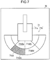
- the icon display part 70 displays an icon 71 indicative of the position of the object A (see FIG. 1 ) with respect to the working machine 1 (see FIG. 1 ).
- the icon display part 70 is disposed, for example, in the cab 13a (see FIG. 1 ). In a case that the working machine 1 is remotely controlled, the icon display part 70 may be disposed outside the working machine 1 (see FIG. 1 ).
- the icon display part 70 is a part or the whole of a display.
- the icon 71 includes a working machine icon 71a and an area icon 71b.
- the working machine icon 71a is, for example, a graphic representing the working machine 1 (see FIG. 1 ) in a plan view.
- the area icon 71b has graphics representing a plurality of areas (71bDa, 71bDb, 71bDc, and 71bDd) around the working machine 1 (see FIG. 1 ) in a plan view.
- the plurality of areas (71bDa, 71bDb, 71bDc, and 71bDd) of the area icon 71b corresponds to the plurality of divisions Da, Db, Dc, and Dd shown in FIG. 4 , respectively.
- the boundaries of the area icon 71b (see FIG. 7 ) shown in FIG. 7 correspond to the boundaries B in the captured image Im shown in FIG. 4 .
- the area (entered area icon 71b1, see FIG. 7 ) of the area icon 71b (see FIG.
- the color of the entered area icon 71b1 shown in FIG. 7 is changed, or alternatively the brightness thereof may be changed in comparison with the rest of the area icon 71b.
- the entered area icon 71b1 may blink. The highlighting of the entered area icon 71b1 enables the operator to easily recognize where the object A is with respect to the working machine 1 shown in FIG. 1 .
- the captured image display part 80 displays the captured image Im (see FIG. 4 ).
- the captured image display part 80 is disposed, for example, in the cab 13a shown in FIG. 1 . In a case that the working machine 1 is remotely controlled, the captured image display part 80 (see FIG. 2 ) may be disposed outside the working machine 1.
- the captured image display part 80 is a part or the whole of a display.
- the captured image display part 80 displays the captured image Im (see FIG. 4 ) taken by the image capturing device 23, with the captured image Im being horizontally inverted like an image reflected in a rearview mirror seen from the cab 13a.
- the captured image display part 80 may display the captured image Im shown in FIG.
- the captured image display part 80 switches and displays respective captured images Im of the image capturing devices 23, or alternatively may display a captured image Im obtained by merging captured images Im taken by the plurality of image capturing devices 23.
- the captured image display part 80 displays a captured image Im of the image capturing device 23 (see FIG. 1 ) that captures the object A within the detection region D shown in FIG. 4 , allowing the operator to recognize the position where the object A is detected and what the object A is, without manually switching the captured images Im.
- the responsive action part 90 executes a predetermined responsive action in a case that the object is in the detection region D.
- the responsive action executed by the responsive action part 90 shown in FIG. 2 is a warning, or may be a restriction to an operation of the working machine 1 or another action.
- the warning is given, for example, to the operator of the working machine 1 or to the worker around the working machine 1.
- the warning is by sound, or may be by light or by an image (including a text, a graphic) on a display, or a combination thereof.
- the responsive action executed by the responsive action part 90 is a restriction to an operation of the working machine 1
- the restriction is, for example, slowing down or stopping the operation of the working machine 1.
- the operation of the working machine 1 restricted by the responsive action part 90 is traveling of the lower traveling body 11 shown in FIG. 1 , or may be slewing of the upper slewing body 13 with respect to the lower traveling body 11, or an operation of the attachment 15.
- the responsive action part 90 may change the responsive action according to the region boundary Bx that is crossed by the object A.
- the responsive action part 90 may make higher the degree of a warning or a restriction as the object A crosses a closer region boundary Bx to the working machine 1 (to the captured image lower side Y2).
- the responsive action part 90 changes the pattern of the warning (e.g., the contents, the number of times, the duration of the warning) or the degree of the restriction to an operation of the working machine 1 according to the region boundary Bx that is crossed by the object A.
- the coordinate calculation part 41a calculates the position (coordinate) of the object A in the captured image Im shown in FIG. 4 as follows. As shown in FIG. 6 , the coordinate calculation part 41a encloses the object A with a polygonal frame K.
- the frame K is, for example, quadrangular, e.g., rhombic or rectangular.
- the coordinate calculation part 41a sets a straight line L which passes the lowermost point Kb that is on the frame K and extends in the captured image left-right direction X.
- a point which is on the straight line L and attributes in the captured image vertical direction Y to a lower left point Kl (a first apex that is at the captured image lower side Y2 and the captured image left side Xl) of the plurality of apexes of the frame K is defined as a left end point Ll (first end point).
- a point which is on the straight line L and attributes in the captured image vertical direction Y to a lower right point Kr (a second apex that is at the captured image lower side Y2 and the captured image right side Xr) of the plurality of apexes of the frame K is defined as a right end point Lr (second end point).
- the point (middle point) in the middle of the left end point Ll and the right end point Lr is defined as a midpoint Lc.
- the coordinate calculation part 41a shown in FIG. 2 determines one of the left end point Ll, the right end point Lr, and the midpoint Lc shown in FIG. 6 as a coordinate indicative of the position of the object A according to an operation pattern of the operating part 21. In this determination, the coordinate calculation part 41a (see FIG. 2 ) determines the one at the closest position to the working machine 1 (see FIG. 1 ) as the coordinate of the object A. The coordinate calculation part 41a is not required to determine the precisely closest one (the closest point) to the working machine 1 as the coordinate of the object A. The coordinate calculation part 41a may determine a position in the vicinity of the closest point of the object A to the working machine 1 as the coordinate of the object A. The coordinate calculation part 41a preferably determines the closest point of the object A to the working machine 1 as the coordinate of the object A.
- the position of the object A in the captured image Im shifts to the captured image right side Xr and the captured image lower side Y2 as shown in FIG. 5 .
- the captured image Im shown in FIG. 5 which is taken by the image capturing device 23 (see FIG. 1 ), is not horizontally inverted.
- the lower right point Kr on the frame K is a position closest to the captured image lower side Y2 (to the side of the working machine 1).
- the coordinate calculation part 41a shown in FIG. 2 determines the right end point Lr shown in FIG.
- the coordinate calculation part 41a shown in FIG. 2 determines the left end point Ll shown in FIG. 6 as the coordinate of the object A when the upper slewing body 13 is slewed to the right with respect to the lower traveling body 11 shown in FIG. 1 by the slewing operating part 21b.
- the "slewed to the right" above means the slewing of the upper slewing body 13 with respect to the lower traveling body 11 such that the background taken in the captured image Im shifts to the captured image left side Xl.
- the closest position to the working machine 1 can be set as the coordinate of the object A shown in FIG. 6 in the case that the upper slewing body 13 shown in FIG. 1 is slewed.
- the coordinate calculation part 41a shown in FIG. 2 determines the midpoint Lc shown in FIG. 6 as the coordinate of the object A when the lower traveling body 11 (see FIG. 1 ) is traveled by the travel operating part 21a.
- the coordinate calculation part 41a shown in FIG. 2 determines the midpoint Lc shown in FIG. 6 as the coordinate of the object A when the lower traveling body 11 is traveled toward the object A shown in FIG. 6 by the travel operating part 21a.
- the area icon 71b (see FIG. 7 ) that corresponds to the division Dc where most of the object A shown in FIG. 4 is present, is highlighted as an entered area icon 71b1 (see FIG. 7 ). Therefore, the operator can recognize the position of the object A more accurately.
- the coordinate calculation part 41a shown in FIG. 2 may determine the midpoint Lc shown in FIG. 6 as the coordinate of the object A in the case that no operation is performed by the operating part 21.
- the right end point Lr or the left end point L1 shown in FIG. 6 may be determined as the coordinate of the object A on the basis of the operation of the slewing operating part 21b.
- the lowermost point Kb shown in FIG. 4 is set as the coordinate of the object A at all times.
- the lowermost point Kb is in the division Dd.
- most of the object A is present in the division Dc.
- the icon display part 70 shown in FIG. 7 highlights the area icon 71b (71bDd) corresponding to the division Dd.
- the captured image display part 80 shown in FIG. 4 displays a captured image Im indicating that most of the object A is in the division Dc. Therefore, the operator may think that the area highlighted as the entered area icon 71b1 on the icon display part 70 shown in FIG.
- the detection region D for the object A displayed on the captured image display part 80 shown in FIG. 4 do not coincide with each other.
- the detection region D and the boundary B are not required to be displayed on the captured image display part 80 shown in FIG. 4 .
- the operator is more likely to think that the display contents on the icon display part 70 (see FIG. 7 ) and on the captured image display part 80 do not agree with each other.
- the midpoint Lc shown in FIG. 4 is determined as the coordinate of the object A for an operation of the operating part 21 shown in FIG. 2 .
- the area icon 71b (71bDc) shown in FIG. 7 which corresponds to the division Dc where most of the object A is present, is highlighted as the entered area icon 71b1, thereby preventing the above-mentioned problem.
- the specifying part 41 shown in FIG. 2 specifies the object A in the captured image Im (Step S11), and calculates the coordinate of the object A (e.g., the coordinate under the feet) (Step S12).
- the coordinate of the object A in the captured image vertical direction Y falls below the coordinate (a predetermined value) of the region boundary Bx in the captured image vertical direction Y (Step S13)
- the responsive action control part 63 outputs an order to the responsive action part 90 (Step S14).
- Step 1 The position of the object A in the captured image Im is calculated.
- Step 2 A coordinate in the captured image Im is converted into a coordinate on a virtual plane based on the working machine 1 shown in FIG. 1 (A region on the virtual plane is created).
- Step 3 The coordinate of the object A on the virtual plane is calculated.
- Step 4 The distance from the working machine 1 to the object A on the virtual plane is calculated.
- Step 5 A responsive action (e.g., a warning, an operational restriction) is executed when the distance from the working machine 1 to the object A falls below a predetermined value.
- a responsive action e.g., a warning, an operational restriction
- Steps 2, 3, and 4 above require complicated processes, resulting in a high processing load and a long processing time.
- a calculation of a coordinate of the object A on the virtual plane requires information on an attachment position and an attachment angle of the image capturing device 23 (see FIG. 1 ), and the logic of the calculation is complicated.
- a long processing time prolongs the time between an entry by the object A into the detection region D (crossing of the object A over the region boundary Bx) and the starting of the responsive action (or delaying the responsive action).
- the attachment position and the attachment angle of the image capturing device 23 vary according to the kind and the specifics of the working machine 1. Thus, it is required to set parameters according to the kind and the specifics of the working machine 1, which is laborious (complicated).
- a coordinate in the captured image Im is not converted into a coordinate on a virtual plane (see FIG. 3 ), enabling omission of the processes in Steps 2, 3, and 4 above.
- the processing load on the control part 30 can be reduced; the processing speed can be increased; and the processing time can be shortened. Accordingly, the time between the entry by the object A into the detection region D and the starting of a responsive action (a warning, an operational restriction) can be shortened (i.e., the responsive action can be quickly executed).
- a coordinate in the captured image Im is not converted into a coordinate on the virtual plane, information on the attachment position and the attachment angle of the image capturing device 23 (see FIG. 1 ) is not required.
- the surroundings observation device 20 is applicable to various kinds of the working machines 1 (i.e., has high versatility).
- the object A is specified with a sensor (e.g., Time Of Flight (TOF) sensor, ultrasonic sensor, infrared sensor, or radio wave (such as millimeter waves) sensor) which acquires dimensional information
- TOF Time Of Flight
- the object A is specified only in a part of the captured image Im as described above, thereby reducing the processing load and shortening the processing time.
- omission of the processes other than that of specifying the object A results in reducing the processing load on the control part 30 and shortening the processing time.
- the surroundings observation device 20 can detect the person only as a detection target; however, a sensor which acquires dimensional information cannot detect the person only as the detection target.
- calculation of a coordinate of the closest point of the object A from dimensional information acquired by a sensor which can acquire dimensional information allows an output of a more accurate coordinate of the closest point.
- the coordinate of the object A is determined on the basis of an operation of the operating part 21 (see FIG. 2 ), resulting in obtaining an accurate coordinate of the closest point.
- the effects exerted by a surroundings observation device 20 for use in a working machine 1 shown in FIG. 2 are as follows.
- the surroundings observation device 20 includes an image capturing device 23, an operating part 21, a specifying part 41, a first setting part 51, and a responsive action part 90.
- the image capturing device 23 is provided on the working machine 1 and takes a captured image Im of surroundings including an object A (see FIG. 4 ) around the working machine 1.
- the operating part 21 is for operating the working machine 1.
- the specifying part 41 specifies a position of the object A (see FIG. 4 ) in the captured image Im.
- the first setting part 51 sets, in the captured image Im shown in FIG. 4 , a detection region D where the object A is to be detected.
- the responsive action part 90 executes a predetermined responsive action in a case that the object A is in the detection region D in the captured image Im.
- a side closer to the working machine 1 is defined as a captured image lower side Y2 (to-machine side); a side farther away from the working machine 1 is defined as a captured image upper side Y1 (fro-machine side); and a direction in which the object A approaches or moves away from the working machine 1 by the shortest distance is defined as a forward direction (in FIG. 4 , corresponding to the captured image vertical direction Y).
- a direction orthogonal to the captured image vertical direction Y is defined as a captured image left-right direction X (front orthogonal direction); one side in the captured image left-right direction X is defined as a captured image right side Xr (first side); and the opposite side to the captured image right side Xr in the captured image left-right direction X is defined as a captured image left side Xl (second side).
- the specifying part 41 (see FIG. 2 ) encloses the object A with a polygonal frame K in the captured image Im and sets a straight line L which passes the lowermost point Kb that is on the frame K and extends in the captured image left-right direction X.
- a point which is on the straight line L and attributes in the captured image vertical direction Y to a lower left point Kl on the frame K is defined as a left end point Ll (second end point);
- a point which is on the straight line L and attributes in the captured image vertical direction Y to a lower right point Kr on the frame K is defined as a right end point Lr (first end point);
- a point in the middle of the left end point Ll and the right end point Lr is defined as a midpoint Lc.
- Configuration 1-2 The specifying part 41 shown in FIG. 2 determines one of the left end point Ll, the right end point Lr, and the midpoint Lc shown in FIG. 6 as a coordinate indicative of the position of the object A according to an operation pattern of the operating part 21.
- Configuration 1-1 a responsive action is executed in a case that the object A is in the detection region D set in the captured image Im.
- the surroundings observation device 20 does not require a complicated process such as a calculation of a distance on a virtual plane from the working machine 1 to the object A after a conversion of a coordinate of the object A in the captured image Im to a coordinate on the virtual plane, thereby reducing a processing load required for the detection of the object A and shortening processing time.
- a delay of the responsive action by the responsive action part 90 in the case that the object A is in the detection region D can be reduced.
- the closest point of the object A to the working machine 1 varies according to an operation of the working machine 1 shown in FIG. 4 . How the working machine 1 is operated depends on the operation pattern of the operating part 21 shown in FIG. 2 .
- the surroundings observation device 20 includes Configuration 1-2 and thereby can determine the closest position to the working machine 1 as the coordinate of the object A shown in FIG. 4 according to the operation pattern of the operating part 21.
- the closest position to the working machine 1 can be determined as the coordinate of the object A, resulting in an early detection of the object A.
- the working machine 1 includes a lower traveling body 11 and an upper slewing body 13 capable of slewing with respect to the lower traveling body 11.
- the specifying part 41 determines the left end point Ll shown in FIG. 6 as the coordinate of the object A when the upper slewing body 13 is slewed (e.g., to the right) with respect to the lower traveling body 11 shown in FIG. 1 by the operating part 21 (slewing operating part 21b) shown in FIG. 2 so that a background taken in the captured image Im shown in FIG. 4 shifts to the captured image left side Xl.
- the specifying part 41 determines the right end point Lr shown in FIG. 6 as the coordinate of the object A when the upper slewing body 13 is slewed (e.g., to the left) with respect to the lower traveling body 11 shown in FIG. 1 by the slewing operating part 21b (see FIG. 2 ) so that the background taken in the captured image Im shown in FIG. 4 shifts to the captured image right side Xr.
- Configuration 2 allows setting the closest position to the working machine 1 shown in FIG. 4 as the coordinate of the object A for a direction of the slewing (to the right or left) of the upper slewing body 13 shown in FIG. 1 , resulting in an early detection of the object A.
- Configuration 3 The specifying part 41 shown in FIG. 2 determines the midpoint Lc shown in FIG. 6 as the coordinate of the object A when the lower traveling body 11 (see FIG. 1 ) of the working machine 1 is traveled by the operating part 21 (travel operating part 21a).
- Configuration 3 allows determining the closest position to the working machine 1 as the coordinate of the object A when the lower traveling body 11 (see FIG. 1 ) is traveled, resulting in an early detection of the object A.
- the surroundings observation device 20 includes an icon display part 70 as shown in FIG. 2 .
- the first setting part 51 sets a plurality of divisions Da to Dd in the captured image Im as shown in FIG. 4 .
- the icon display part 70 displays an area icon 71b indicative of a plurality of areas around the working machine 1 (see FIG. 1 ) corresponding to the divisions Da to Dd (see FIG. 4 ).
- the icon display part 70 highlights the area icon 71b (entered area icon 71b1) that corresponds to the division where the object A is in the captured image Im shown in FIG. 4 .
- Configuration 4 enables the operator looking at the icon display part 70 shown in FIG. 7 to recognize which area around the working machine 1 (see FIG. 1 ) the division (the region in the captured image Im) where the object A is corresponds to, thereby encouraging the operator to perform an appropriate avoiding operation (operation of avoiding a contact of the working machine 1 with the object A).
- the surroundings observation device 20 shown in FIG. 2 includes a captured image display part 80 for displaying the captured image Im and a plurality of image capturing devices 23 shown in FIG. 1 .
- the captured image display part 80 shown in FIG. 2 displays a captured image Im (see FIG. 4 ) of the image capturing device 23 (see FIG. 1 ) that captures the division (see FIG. 4 ) corresponding to the highlighted area icon 71b (entered area icon 71b 1, see FIG. 7 ).
- Configuration 5 allows for confirming a background that is in the division where the object A is and the object A on the captured image display part 80 as shown in FIG. 4 , thereby enabling the operator to recognize the position of the object A and what the object A is.
- the first setting part 51 sets a division boundary By which divides a plurality of divisions in a juxtaposition of the captured image left-right direction X.
- the division boundary By extends linearly in the captured image vertical direction Y.
- Configuration 6 results in: reducing a processing load caused by the determination as to which of the divisions juxtaposed in the captured image left-right direction X the object A is in; and shortening processing time, in comparison with a case that the division boundary By is not linear (is curved).
- the first setting part 51 sets a region boundary Bx that is a limit of the detection region D in the captured image Im.
- the region boundary Bx extends in the captured image left-right direction X and has a certain shape.
- Configuration 8 results in reducing the processing load caused by a determination as to whether or not the object A is in the detection region D (see Configuration 1-1 above) in comparison with a case that the shape of the region boundary Bx is changeable.
- the processing load required for the detection of the object A can be reduced and the processing time can be shortened, thereby reducing a delay of the responsive action by the responsive action part 90 (see FIG. 2 ) in the case that the object A is in the detection region D.
- Configuration 9 The region boundary Bx is linear in the captured image Im.
- Configuration 8 results in further reducing the processing load caused by the determination as to whether or not the object A is in the detection region D (see Configuration 1-1 above).
- the surroundings observation device 20 includes a second setting part 45 as shown in FIG. 2 .
- the second setting part 45 sets, in the captured image Im, a high distortion region Fb (first distortion region) and a low distortion region Fa (second distortion region) which is less distorted than the high distortion region Fb.
- the region boundary Bx is set in the low distortion region Fa.
- the region boundary Bx is set in the low distortion region Fa, which allows the responsive action start distance to be uniform or substantially uniform regardless of the position of the object A in the captured image left-right direction X of the captured image Im, enabling the operator to easily grasp the responsive action start distance (i.e., the operator easily grasps the sense of distance), thereby encouraging the operator to perform the appropriate avoiding operation.
- the surroundings observation device 20 includes a third setting part 53 as shown in FIG. 2 .
- the third setting part 53 sets, in the captured image Im, a boundary upper limit position Ga (first utmost position) and a boundary lower limit position Gb (second utmost position) closer to the captured image lower side Y2 than the boundary upper limit position Ga as shown in FIG. 4 .
- the region boundary Bx is set within a region between the boundary upper limit position Ga and the boundary lower limit position Gb.
- Configuration 11 A part of the captured image upper side Y1 and a part of the captured image lower side Y2 in the captured image Im are presumed to be an inappropriate position for the region boundary Bx (e.g., because of having the sky or the lower traveling body 11).
- the region boundary Bx is set within a region between the boundary upper limit position Ga and the boundary lower limit position Gb, enabling an appropriate detection of the object A. For example, a misdetection of detecting an object other than the object A as the object A can be prevented.
- the surroundings observation device 20 includes an adjusting part 52 (see FIG. 2 ) for adjusting the position of the region boundary Bx in the captured image vertical direction Y.
- the view angle and the attachment angle of the image capturing device 23 are liable to vary within a range of tolerance.
- a fixed position of the region boundary Bx in the captured image vertical direction Y causes the responsive action start distance to vary.
- an adjustment of the position of the region boundary Bx by the adjusting part 52 serves as an adjustment of the responsive action start distance.
- the responsive action start distances can be adjusted to be a predetermined distance regardless of the variation in the view angle and the attachment angle of the image capturing devices 23 (i.e., the variation in the view angle and the attachment angle of the image capturing devices 23 can be offset).
- the responsive action start distance is required to be changed according to the situation of the working place where the working machine 1 is.
- the responsive action start distance can be changed by adjusting the position of the region boundary Bx with the adjusting part 52, resulting in improvement of usability.
- the surroundings observation device 20 (see FIG. 2 ) that includes Configurations 11 and 12 above adjusts the position of the region boundary Bx within a region between the boundary upper limit position Ga and the boundary lower limit position Gb.
- the region boundary Bx is set so that the object A can be appropriately detected, thereby eliminating a wrong adjustment of, for example, adjusting the position of the region boundary Bx to an inappropriate position (e.g., because of having the sky or the lower traveling body 11), resulting in an improvement in the adjustability of the position of the region boundary Bx.
- Configuration 13 The position of the region boundary Bx in the captured image Im when a travel speed of the working machine 1 to the object A is a first speed is defined as a first position Bx1.
- the position of the region boundary Bx in the captured image Im when the travel speed of the working machine 1 to the object A is a second speed higher than the first speed is defined as a second position Bx2.
- the adjusting part 52 sets the second position Bx2 to be above the first position Bx1 (closer to the captured image upper side Y1) in the captured image Im.
- Configuration 13 can make the object A enter the detection region D at a position farther away from the working machine 1 (i.e., make the responsive action start distance longer) in the case that the travel speed of the working machine 1 is the second (higher) speed, in comparison with the case of the first (lower) speed.
- the responsive action can be started earlier in the case of the second (higher) speed than in the case of the first (lower) speed.
- the first setting part 51 (see FIG. 2 ) further sets a standard line Bx in a portion closer to the working machine 1 than the region boundary Bx that is the limit between the detection region D and the non-detection region C.
- the responsive action part 90 (see FIG. 2 ) changes the responsive action according to whether the position of the object A is closer to or farther away from the working machine 1 than the standard line Bx.
- Configuration 14 above allows a change of the responsive action (e.g., a warning, an operational restriction) according to the distance from the working machine 1 to the object A, enabling an appropriate notification to the operator of, for example, the position of the object A.
- a responsive action e.g., a warning, an operational restriction
- Configuration 15 A plurality of image capturing devices 23 (see FIG. 1 ) are provided.
- the first setting part 51 sets a region boundary Bx on each captured image Im taken by the plurality of image capturing devices 23 (see FIG. 1 ).
- Configuration 15 above allows setting the responsive action start distance for each image capturing device 23, thereby providing an improved usability. Specifically, each view angle, attachment angle, and attachment position of the plurality of image capturing devices 23 shown in FIG. 1 vary. Thus, if a region boundary Bx is set at a common position for the captured image Im of each image capturing device 23, the responsive action start distance for each image capturing device 23 varies. In this regard, in Configuration 15, a region boundary Bx is set for each image capturing device 23, allowing each responsive action start distance of the plurality of image capturing devices 23 to be uniform or substantially uniform.
- the surroundings observation device 20 includes a delimiting part 43 as shown in FIG. 2 .
- the delimiting part 43 sets a specific upper limit position Ea (first limit position) in the captured image Im as shown in FIG. 4 .
- the specifying area in which the specifying part 41 specifies the object A is within a region closer to the captured image lower side Y2 than the specific upper limit position Ea.
- Configuration 16 A part of the captured image upper side Y1 in the captured image Im is presumed to be an inappropriate position (e.g., because of having the sky) for specifying the object A.
- the specifying area in which the specifying part 41 specifies the object A is within a region closer to the captured image lower side Y2 than the specific upper limit position Ea.
- the object A can be specified appropriately.
- the specifying area of the specifying part 41 (see FIG. 2 ) can be limited in comparison with the case that the specifying part 41 specifies the object A in the whole of the captured image Im, thereby reducing the processing load on the specifying part 41 (see FIG. 2 ) and shortening the processing time.
- the surroundings observation device 20 includes a delimiting part 43 as shown in FIG. 2 .
- the delimiting part 43 sets a specific lower limit position Eb (second limit position) in the captured image Im as shown in FIG. 4 .
- the specifying area in which the specifying part 41 specifies the object A is within a region closer to the captured image upper side Y1 than the specific lower limit position Eb.
- Configuration 17 A part of the captured image lower side Y2 in the captured image Im is presumed to be an inappropriate position (e.g., because of having only the upper slewing body 13 (see FIG. 1 )) for specifying the object A.
- the specifying area in which the specifying part 41 specifies the object A is within a region closer to the captured image upper side Y1 than the specific lower limit position Eb.
- the object A can be specified appropriately.
- the specifying area can be limited, thereby reducing the processing load on the specifying part 41 (see FIG. 2 ) and shortening the processing time.
- the surroundings observation device 20 includes a second setting part 45 as shown in FIG. 2 .
- the second setting part 45 sets respective high distortion regions Fb (fourth distortion region and third distortion region) in the captured image upper side Y1 and the captured image lower side Y2.
- the second setting part 45 sets a low distortion region Fa (second distortion region) having less image distortion than the high distortion region Fb.
- the specifying area in which the specifying part 41 specifies the object A is within the low distortion region Fa and the high distortion region Fb in the captured image lower side Y2.
- the region where there is more distortion, which is a part of the captured image upper side Y1 is presumed to be an inappropriate position (e.g., because of having the sky) for specifying the object A.
- the specifying area in which the specifying part 41 specifies the object A is within the low distortion region Fa and the high distortion region Fb in the captured image lower side Y2.
- the object A can be specified appropriately.
- the specifying area of the specifying part 41 (see FIG. 2 ) can be limited in comparison with the case that the specifying part 41 specifies the object A in the whole of the captured image Im, thereby reducing the processing load on the specifying part 41 (see FIG. 2 ) and shortening the processing time.
- the divisions of the detection region D (see FIG. 8 ) and the area icon 71b (see FIG. 9 ) may be subdivided in comparison with the case shown in FIGS. 4 and 7 .
- the subdivision of the divisions of the detection region D and the area icon 71b allows the operator looking at the icon display part 70 (see FIG. 9 ) to be informed of a more specific position of the object A shown in FIG. 1 and to grasp a more specific position of the object A with respect to the working machine 1.
- the captured image Im depicts an object A closer to the working machine 1 in a larger size and an object A farther away from the working machine 1 in a smaller size. Therefore, it is preferable to set a division farther away from the working machine 1 (in the captured image upper side Y1) to be smaller than a division closer to the working machine 1 (in the captured image lower side Y2) in the captured image Im.
- the first setting part 51 sets a plurality of division boundaries By, which are limits of the divisions in the detection region D, apart from each other as shown in FIG. 8 .
- the embodiment described above may include various modifications.
- the connections between the respective constituents in the embodiment shown in FIG. 2 may be changed.
- Each region (e.g., low distortion region Fa) shown in FIG. 4 and each position (e.g., specific upper limit position Ea) for defining a region may be fixed, but these regions or positions may be changed manually, or changed automatically according to a condition.
- the number of constituents may be changed, or alternatively some constituents may be omitted.
- Constituents described as members or parts different from each other may be combined into one member or one part.
- a constituent described as a member or a part may be separately provided as members or parts different from each other.
Landscapes
- Engineering & Computer Science (AREA)
- General Physics & Mathematics (AREA)
- Physics & Mathematics (AREA)
- Theoretical Computer Science (AREA)
- Civil Engineering (AREA)
- General Engineering & Computer Science (AREA)
- Structural Engineering (AREA)
- Mining & Mineral Resources (AREA)
- Computer Vision & Pattern Recognition (AREA)
- Multimedia (AREA)
- Signal Processing (AREA)
- Remote Sensing (AREA)
- Radar, Positioning & Navigation (AREA)
- Mechanical Engineering (AREA)
- Aviation & Aerospace Engineering (AREA)
- Automation & Control Theory (AREA)
- Component Parts Of Construction Machinery (AREA)
- Closed-Circuit Television Systems (AREA)
- Image Analysis (AREA)
- Image Processing (AREA)
Abstract
Description
- The present invention relates to a surroundings observation device for use in a working machine which detects an object around the working machine.
- For example,
Patent Literature 1 discloses a conventional surroundings observation device. In the technique disclosed inPatent Literature 1, a image capturing device takes a captured image of an object (an obstacle in Patent Literature 1). On the basis of the lowermost position of the object in the captured image, a distance from the working machine to the object is calculated (see Paragraph [0027] andFIG. 8 of Patent Literature 1). - However, the lowermost position of the object cannot be always the position closest to the working machine (the closest position) in the captured image. The closest position varies according to operations of the working machine.
- Patent Literature 1:
Japanese Patent No. 6232497 - The object of the present invention is to provide a surroundings observation device for use in a working machine which can determine a closest position of an object to the working machine as a coordinate of the object for an operation of the working machine.
- A surroundings observation device for use in a working machine according to an aspect of the present invention includes: at least one image capturing device which is provided on the working machine to capture an image of an object around the working machine and thereby obtain a captured image; an operating part for operating the working machine; a specifying part for specifying a position of the object in the captured image; a first setting part for setting a detection region where the object is to be detected in the captured image; a responsive action part for executing a predetermined responsive action in a case that the object is in the detection region in the captured image, wherein the specifying part encloses the object with a polygonal frame in the captured image; sets a straight line which passes a point that is on the polygonal frame and is closest to a to-machine side, and extends in a front orthogonal direction, the front orthogonal direction being orthogonal to a forward direction of the working machine in the captured image, and the to-machine side being a side closer to the working machine in the forward direction; sets a first end point which is on the straight line and attributes to a first apex of a plurality of apexes of the polygonal frame that is at a first side on one side in the front orthogonal direction and closer to the to-machine side; sets a second end point which is on the straight line and attributes to a second apex of the plurality of apexes that is at a second side on the other side in the front orthogonal direction and closer to the to-machine side; sets a midpoint between the first end point and the second end point; and determines one of the first end point, the second end point, and the midpoint as a coordinate indicative of the position of the object according to an operation pattern of the operating part.
-
-
FIG. 1 is a plan view of a working machine. -
FIG. 2 is a diagram of a surroundings observation device for use in the working machine shown inFIG. 1 . -
FIG. 3 is a flowchart showing a procedure of a control part shown inFIG. 2 . -
FIG. 4 illustrates a captured image taken by a image capturing device shown inFIG. 2 . -
FIG. 5 is similar toFIG. 4 and illustrates a captured image indicative of a case where an upper slewing body shown inFIG. 1 is slewed. -
FIG. 6 is an illustration showing an object in the captured image shown inFIG. 4 . -
FIG. 7 is an illustration showing an icon displayed on an icon display part shown inFIG. 2 . -
FIG. 8 is similar toFIG. 4 and illustrates a captured image in a modification. -
FIG. 9 is similar toFIG. 7 and illustrates an icon in the modification. - With reference to
FIGS. 1 to 7 , a surroundings observation device 20 (seeFIG. 2 ) for use in a working machine 1 (seeFIG. 1 ) will be described. - As shown in
FIG. 1 , theworking machine 1 is a machine for performing a work, e.g., a construction machine for performing a construction work. The construction machine is, for example, an excavator (e.g., hydraulic excavator) or a crane. The following description will be made about the case where the workingmachine 1 serves as an excavator. The workingmachine 1 includes alower traveling body 11, anupper slewing body 13, and anattachment 15. - The lower traveling
body 11 causes the workingmachine 1 to travel. The lower travelingbody 11 includes, for example, a crawler, or may include a blade. - The
upper slewing body 13 is slewably mounted on the lower travelingbody 11. Theupper slewing body 13 includes acab 13a and acounterweight 13b. Thecab 13a is a section allowing an operator to operate the workingmachine 1 aboard. Thecounterweight 13b is a weight for balancing theworking machine 1 in the longitudinal direction thereof. - The
attachment 15 is a portion for performing a work and includes, for example, aboom 15a, anarm 15b, and a leadingend attachment 15c. Theboom 15a is raisably and lowerably attached to theupper slewing body 13. Thearm 15b is rotatably attached to theboom 15a. The leadingend attachment 15c is provided on a leading end portion of theattachment 15, and is rotatably attached to thearm 15b. The leadingend attachment 15c may be a bucket for shoveling up earth and sand, a device (such as a grapple) for nipping an article, or a device (such as a breaker) for crush and excavation. - The
surroundings observation device 20 detects an article (object A) around theworking machine 1. Thesurroundings observation device 20 detects the object A on the basis of a captured image Im (seeFIG. 4 ). The object A is a person (worker) around theworking machine 1, or may be an obstacle other than the person around theworking machine 1. As shown inFIG. 2 , thesurroundings observation device 20 includes anoperating part 21, an image capturingdevice 23, acontrol part 30, anicon display part 70, a capturedimage display part 80, and aresponsive action part 90. - The
operating part 21 is a section for allowing the operator to operate the working machine 1 (seeFIG. 1 ). Theoperating part 21 is disposed in thecab 13a (seeFIG. 1 ). In the case that theworking machine 1 is remotely controlled, theoperating part 21 may be disposed at a position away from the working machine 1 (seeFIG. 1 ). Theoperating part 21 includes atravel operating part 21a, a slewing operatingpart 21b, and aninput device 21c for adjusting a boundary. Thetravel operating part 21a is a section for causing the lower traveling body 11 (seeFIG. 1 ) to travel (specifically, forward and backward). Thetravel operating part 21a is a lever (control lever) (the same is applied to theslewing operating part 21b). The slewing operatingpart 21b is a section for slewing (to the right and to the left) the upper slewing body 13 (seeFIG. 1 ) with respect to the lower traveling body 11 (seeFIG. 1 ). Theinput device 21c is adapted for adjusting a position of a boundary B (seeFIG. 4 ), which will be described later. Theinput device 21c includes, for example, a jog dial 21cl and a switch 21c2 (e.g., a push switch). The jog dial 21cl and the switch 21c2 are integrated, or may be separated. - The image capturing
device 23 takes a captured image Im (seeFIG. 4 ) of surroundings including the object A as shown inFIG. 1 . The image capturingdevice 23 monitors the surroundings of theworking machine 1. The image capturingdevice 23 is fixedly attached to theupper slewing body 13. The captured imaging range of theimage capturing device 23 preferably covers the blind spots from the operator in thecab 13a. The number of theimage capturing device 23 is one, or may be more. The image capturingdevice 23 is disposed, for example, on a rear portion (e.g., on thecounterweight 13b or in the vicinity thereof), a right portion, and a left portion of theupper slewing body 13. In a case that theworking machine 1 is remotely controlled, theimage capturing device 23 may be disposed on a front portion (e.g., in thecab 13a) of theupper slewing body 13. The image capturingdevice 23 can captured image over a wide range, for example, with a fisheye lens. - The captured image Im (see
FIG. 4 ) taken by theimage capturing device 23 is a twodimensional image (specifically, video frame), or may be a three-dimensional image (e.g., a captured image taken by a stereo camera). In the captured image Im shown inFIG. 4 , a side closer to theworking machine 1 is defined as a captured image lower side Y2 (to-machine side) and a side farther away from theworking machine 1 is defined as a captured image upper side Y1 (fro-machine side). In the captured image Im, a direction in which the captured image upper side Y1 and the captured image lower side Y2 are connected is defined as a captured image vertical direction Y (forward direction). In the captured image Im, a direction in which the object A approaches or moves away from the workingmachine 1 by the shortest distance is defined as a forward direction (inFIG. 4 , corresponding to the captured image vertical direction Y). In the captured image Im, a direction orthogonal to the forward direction is defined as a front orthogonal direction (inFIG. 4 , corresponding to a captured image left-right direction X). One side in the captured image left-right direction X is defined as a captured image right side Xr (a first side). The opposite side to the captured image right side Xr in the captured image left-right direction X is defined as a captured image left side Xl (a second side). Since the terms "upper", "lower", "left", "right" are merely used for convenience of explanation, theimage capturing device 23 may be turned or inversed. - The control part 30 (see
FIG. 2 ) performs inputting and outputting of information, computations (determination and settings), and storing of information. Thecontrol part 30 shown inFIG. 2 is disposed on the upper slewing body 13 (seeFIG. 1 ), or may be disposed outside the upper slewing body 13 (e.g., in a server). For example, some constituents of thecontrol part 30 are disposed on theupper slewing body 13 and the other constituents thereof are disposed outside theupper slewing body 13. Thecontrol part 30 includes animage correction part 31, a specifyingpart 41, a delimitingpart 43, afirst setting part 51, asecond setting part 45, athird setting part 53, an adjustingpart 52, adetermination part 61, a responsiveaction control part 63, and adisplay control part 65. - The
image correction part 31 corrects the captured image Im taken by theimage capturing device 23. Theimage correction part 31 corrects distortion (image distortion) in the captured image Im. Any method is applicable to the correction of the distortion by theimage correction part 31. For example, theimage correction part 31 may reduce the distortion by expanding or contracting the captured image Im. For example, in the captured image Im, theimage correction part 31 may remove a part where there is more distortion while maintaining a part where there is less distortion. A captured image Im resulting from the correction by theimage correction part 31 is also referred to as "captured image Im". - The specifying
part 41 specifies a position of the object A in the captured image Im shown inFIG. 4 . Specifically, the specifying part 41 (seeFIG. 2 ) automatically determines (recognizes, discriminates) by executing image processing whether or not an object in the captured image Im agrees with the object A. The specifyingpart 41 performs the determination on the basis of the features (e.g., shape, color) of the object in the captured image Im. The specifyingpart 41 includes a coordinatecalculation part 41a. The coordinatecalculation part 41a calculates a closest position (coordinate) of the object A to the workingmachine 1 in the captured image Im. For example, the coordinatecalculation part 41a calculates, as the closest position, the coordinate of a part of the object A in the captured image lower side Y2 (e.g., a part under the feet of the worker). The details of the calculation of the coordinate by the coordinatecalculation part 41a will be described later. - The delimiting part 43 (see
FIG. 2 ) can set a specific upper limit position Ea (first limit position) and a specific lower limit position Eb (second limit position) in the captured image Im. The specific upper limit position Ea is preset by the delimitingpart 43, or may be set manually or automatically (the same is applied to the specific lower limit position Eb). In the case that both of the specific upper limit position Ea and the specific lower limit position Eb are set, the specific lower limit position Eb is set to be closer to the captured image lower side Y2 than the specific upper limit position Ea. - Case 1: In the case that the delimiting
part 43 sets the specific upper limit position Ea, a specifying area in which the specifying part 41 (seeFIG. 2 ) specifies the object A is within a region closer to the captured image lower side Y2 than the specific upper limit position Ea. The "within a region" above need not cover the whole of the region, and may be at least a part of the region (hereinafter, the same). The specifyingpart 41 does not specify the object A in a region closer to the captured image upper side Y1 than the specific upper limit position Ea. Case 2: In the case that the delimitingpart 43 sets the specific lower limit position Eb, the specifying area in which the specifying part 41 (seeFIG. 2 ) specifies the object A is within a region closer to the captured image upper side Y1 than the specific lower limit position Eb. The specifyingpart 41 does not specify the object A in a region closer to the captured image lower side Y2 than the specific lower limit position Eb. Case 3: In the case that the delimitingpart 43 sets both of the specific upper limit position Ea and the specific lower limit position Eb, the specifying area in which the specifying part 41 (seeFIG. 2 ) specifies the object A is within a region between the specific upper limit position Ea and the specific lower limit position Eb. The specifyingpart 41 does not specify the object A in a region closer to the captured image upper side Y1 than the specific upper limit position Ea. InCases part 41 does not specify the object A in a part of the captured image Im. Thus, the specifying area of the specifyingpart 41 is limited in comparison with the case that the specifyingpart 41 specifies it in the whole of the captured image Im, thereby reducing the processing load and shortening the processing time. The specific upper limit position Ea and the specific lower limit position Eb are set on the basis of, for example, the necessity of specifying the object A. - The specific upper limit position Ea is set as follows. There is a case that a part of the captured image upper side Y1 in the captured image Im has the sky. Specifying the object A in a part having the sky is likely to cause excessive detection or misdetection. Therefore, the specific upper limit position Ea is set on the basis of a part which is presumed to have the sky. For example, the specific upper limit position Ea is set such that a part which is presumed to have the sky is closer to the captured image upper side Y1 than the specific upper limit position Ea.
- The specific lower limit position Eb is set as follows. There is a case that a part of the captured image lower side Y2 in the captured image Im has a part of the upper slewing body 13 (see
FIG. 1 ). In this case, the part that has theupper slewing body 13 does not bear the object A. Therefore, the delimitingpart 43 sets the specific lower limit position Eb on the basis of a part which is presumed to have theupper slewing body 13. For example, the delimitingpart 43 sets the specific lower limit position Eb such that a part which is presumed to have theupper slewing body 13 is closer to the captured image lower side Y2 than the specific lower limit position Eb. - The second setting part 45 (see
FIG. 2 ) sets, in the captured image Im, a high distortion region Fb (first distortion region) and a low distortion region Fa (second distortion region). The high distortion region Fb is preset by thesecond setting part 45, or may be manually or automatically set (the same is applied to the low distortion region Fa). The low distortion region Fa has less image distortion than the high distortion region Fb. - The
second setting part 45 sets the high distortion region Fb and the low distortion region Fa as follows. There is a case that a part of the captured image upper side Y1 and a part of the captured image lower side Y2 are more distorted than a middle part in the captured image vertical direction Y. Therefore, the part of the captured image upper side Y1 and the part of the captured image lower side Y2 in the captured image Im are set as high distortion regions Fb, and the part other than the high distortion regions Fb in the captured image Im is set as a low distortion region Fa. As described above, the part of the captured image upper side Y1 in the captured image Im is presumed to have the sky; thus, omission of specifying the object A therein will not cause the problem. In other words, the specifying area in which the specifying part 41 (seeFIG. 2 ) specifies the object A is within the low distortion region Fa and the high distortion region Fb in the part of the captured image lower side Y2 (i.e., third distortion region). The specifyingpart 41 does not specify the object A in the high distortion region Fb in the part of the captured image upper side Y1 (i.e., fourth distortion region). Thus, in comparison with the case that the specifyingpart 41 specifies it in the whole of the captured image Im, the specifying area of the specifyingpart 41 is limited, thereby reducing the processing load and shortening the processing time. On the other hand, the specifyingpart 41 specifies the object A in the high distortion region Fb in the part of the captured image lower side Y2, enabling an appropriate detection of the object A approaching the workingmachine 1. - There may be a case that all of the specific upper limit position Ea, the specific lower limit position Eb, the high distortion region Fb, and the low distortion region Fa are set. In this case, the specifying part 41 (see
FIG. 2 ) specifies the object A in a region that is between the specific upper limit position Ea and the specific lower limit position Eb and is in the low distortion region Fa, but not in the other region. The case described above, where a part of the captured image upper side Y1 and a part of the captured image lower side Y2 in the captured image Im are set as high distortion regions Fb and a middle part in the captured image vertical direction Y is set as a low distortion region Fa, is merely an example. Which part of the captured image Im becomes the high distortion region Fb and the low distortion region Fa depends on a view angle and a disposition of theimage capturing device 23, and a correction by theimage correction part 31. - The first setting part 51 (see
FIG. 2 ) sets a detection region D. The detection region D is a region in the captured image Im where the object A is detected, on the basis of which the responsive action part 90 (seeFIG. 2 ) determines whether or not to execute a predetermined responsive action. In the captured image Im, the region other than the detection region D is defined as a non-detection region C. Thefirst setting part 51 sets a plurality of divisions in the captured image Im. InFIG. 4 , thefirst setting part 51 sets four divisions: a lower left division Da, a lower right division Db, an upper left division Dc, and an upper right division Dd. - The
first setting part 51 sets a boundary B that is a limit of the detection region D in the captured image Im. The boundary B includes a region boundary Bx extending in the captured image left-right direction X and a division boundary By extending in the captured image vertical direction Y. It may be appreciated to set one region boundary Bx , or alternatively a plurality of region boundaries Bx. The region boundaries Bx include at least a limit between the detection region D and the non-detection region C. In the case of a plurality of region boundaries Bx, the region boundary Bx farthest away from the working machine 1 (in the image upper side Y1) is the limit (an extremity of the detection region D) between the detection region D and the non-detection region C. The region boundaries Bx may include a line which separates a plurality of detection regions D from one another. Specifically, the region boundaries Bx may include a line (standard line) that separates the division Da from the division Dc and a line (standard line) that separates the division Db from the division Dd. Preferably, the region boundary Bx is set such that the processing load on the control part 30 (seeFIG. 2 ) is minimized. Specifically, the region boundary Bx is a line that extends in the captured image left-right direction X and has a certain (unchangeable) shape. Preferably, the region boundary Bx is substantially linear, more preferably, linear in the captured image Im. The "substantially linear" above covers a curved line along a part (e.g., a rear end of thecounterweight 13b (seeFIG. 1 )) of the upper slewing body 13 (seeFIG. 1 ) in the captured image Im. - Preferably, the region boundary Bx is set in a captured image Im resulting from the correction by the image correction part 31 (see
FIG. 2 ) for the following reason. In a part of the captured image Im where there is more distortion, the actual distance from the workingmachine 1 to the object A considerably varies due to a position of the object A in the captured image left-right direction X even if the position of the object A in the captured image vertical direction Y is fixed. Thus, in the case that a region boundary Bx which is linear or substantially linear is set in a part of the captured image Im where there is more distortion, whether or not the object A is in the detection region D changes according to the position of the object A in the captured image left-right direction X even if the actual distance from the workingmachine 1 to the object A is uniform. Thus, the actual distance (responsive action start distance) between the object A and the workingmachine 1 when the responsive action part 90 (seeFIG. 2 ) starts to execute a responsive action varies according to the position of the object A in the captured image left-right direction X in the captured image Im, which makes it difficult for the operator of the workingmachine 1 to understand by what distance the approach of the object A to the workingmachine 1 causes the responsive action to be started (the operator has difficulty in grasping the sense of distance). On the other hand, in this embodiment, a region boundary Bx that is substantially linear or linear is set in the captured image Im resulting from the correction of distortion by the image correction part 31 (seeFIG. 2 ). Thus, the responsive action start distance is uniform or substantially uniform regardless of the position of the object A in the captured image left-right direction X. Therefore, the operator easily grasps the sense of distance. Additionally, since the responsive action start distance is uniform or substantially uniform, the responsive action is properly executed. - The first setting part 51 (see
FIG. 2 ) sets the region boundary Bx in the low distortion region Fa for the same reason as described above. Thus, the responsive action start distance is substantially uniform regardless of the position of the object A in the captured image left-right direction X, allowing the operator to easily grasp the sense of distance. Additionally, since the responsive action start distance is uniform or substantially uniform, the responsive action is properly executed. Further, as described above, there may be a case that a part of the captured image upper side Y1 in the captured image Im has the sky and a part of the captured image lower side Y2 in the captured image Im has the lower travelingbody 11. Therefore, setting the region boundary Bx in the low distortion region Fa, which is a middle part of the captured image Im in the captured image vertical direction Y, enables an appropriate detection of the object A. Further, since the region boundary Bx is set in the low distortion region Fa, the object A can be detected earlier in comparison with a case that the region boundary Bx is set in the high distortion region Fb closer to the working machine 1 (in the captured image lower side Y2). - The
second setting part 45 sets the low distortion region Fa (second distortion region) where the region boundary Bx may be set, and the high distortion region Fb (first distortion region) where the region boundary Bx may not be set. Thesecond setting part 45 sets the low distortion region Fa (second distortion region) and the high distortion region Fb (third distortion region) in the captured image lower side Y2, where the specifyingpart 41 may perform the specification. Thesecond setting part 45 sets the high distortion region Fb (fourth distortion region) in the captured image upper side Y1, where the specifyingpart 41 does not perform the specification. A low distortion region Fa (first low distortion region), where the region boundary Bx is set, may be identical to or different from a low distortion region Fa (second low distortion region), where the specifyingpart 41 specifies the object A. The range suitable for the first low distortion region does not always coincide with the range suitable for the second low distortion region. Thus, the first low distortion region and the second low distortion region are preferably positioned differently. Only one of the first low distortion region and the second low distortion region may be set. - The first setting part 51 (see
FIG. 2 ) may set a plurality of region boundaries Bx. In this case, thefirst setting part 51 sets the plurality of region boundaries Bx apart from each other in the captured image vertical direction Y. As described later, theresponsive action part 90 changes the responsive action according to the region boundary Bx that is crossed by the object A. - In the case that a plurality of image capturing devices 23 (see
FIG. 1 ) is provided, the first setting part 51 (seeFIG. 2 ) sets a region boundary Bx (for each image capturing device 23) in each of a plurality of captured images Im taken by the plurality ofimage capturing devices 23. Thefirst setting part 51 sets the region boundary Bx such that the responsive action start distance for eachimage capturing device 23 is uniform or substantially uniform. - The
first setting part 51 sets a division boundary By which divides a plurality of divisions in a juxtaposition of the captured image left-right direction X. The division boundary By extends in the captured image vertical direction Y. The division boundary By is a line having a certain (unchangeable) shape. Preferably, the division boundary By is substantially linear, more preferably, linear in the captured image Im. As shown inFIG. 8 , a plurality of division boundaries By may be set. Thefirst setting part 51 may set a plurality of division boundaries By apart from each other in the captured image left-right direction X. Thefirst setting part 51 shown inFIG. 2 includes an adjustingpart 52. - The adjusting
part 52 adjusts the position of the region boundary Bx shown inFIG. 4 in the captured image vertical direction Y. The shape of the region boundary Bx in the captured image Im is fixed regardless of the adjustment of the position of the region boundary Bx by the adjustingpart 52. A change of the position of the region boundary Bx in a part of the captured image Im where there is more distortion requires a change of the curvature of the region boundary Bx in accordance with the distortion of the captured image Im, involving preparation of parameters. However, in this embodiment, the shape of the region boundary Bx is fixed. The adjustment of the position of the region boundary Bx by the adjustingpart 52 is manual, or may be automatic. - For example, the position of the region boundary Bx is manually adjusted as follows. The control part 30 (see
FIG. 2 ) is set in "adjustment mode". The captured image display part 80 (seeFIG. 2 ), which will be described later, then superimposes and displays the region boundary Bx on the captured image Im, at which the operator looks, and performs an operation of determining the position of the region boundary Bx by shifting the region boundary Bx in the captured image vertical direction Y. The operation is performed with theinput device 21c (seeFIG. 2 ). Specifically, the operator determines the position of the region boundary Bx by turning the jog dial 21c1 (seeFIG. 2 ) to shift the region boundary Bx in the captured image vertical direction Y and using (pushing) the switch 21c2 (seeFIG. 2 ). - For example, the position of the region boundary Bx is automatically adjusted as follows. The position of the region boundary Bx is adjusted on the basis of, for example, the travel speed of the working
machine 1. Specifically, the adjusting part 52 (seeFIG. 2 ) determines the position of the region boundary Bx in the captured image Im when the travel speed of the workingmachine 1 to the object A is a first speed as a first position Bx1. A travel speed of the workingmachine 1 to the object A higher than the first speed is defined as a second speed. The position of the region boundary Bx in the captured image Im at the second speed is determined as a second position Bx2. The adjustingpart 52 sets the second position Bx2 to be closer to the captured image upper side Y1 than the first position Bx1. The adjustingpart 52 may set the position of the region boundary Bx in a portion closer to the captured image upper side Y1 step-by-step or consecutively as the travel speed of the workingmachine 1 becomes higher. Whether or not the workingmachine 1 travels toward the object A can be determined on the basis of the direction of the travel (forward, backward) of the lower travelingbody 11, the slewing angle of theupper slewing body 13 with respect to the lower travelingbody 11, and the direction in which theimage capturing device 23 captured images. The position of the region boundary Bx may not be adjusted (i.e., the adjustingpart 52 may not be provided). There may be a case that thefirst setting part 51 presets a region boundary Bx and the position of the region boundary Bx is unchanged. - In the case that the adjusting
part 52 adjusts the position of the region boundary Bx, the adjustingpart 52 acquires directly or indirectly the travel speed of the workingmachine 1. For example, the adjustingpart 52 shown inFIG. 2 acquires the travel speed on the basis of the operation amount of thetravel operating part 21a. The adjustingpart 52 may acquire the travel speed on the basis of information (number of rotations, flow amount of hydraulic oil) on a motor for causing the lower traveling body 11 (seeFIG. 1 ) to travel. The adjustingpart 52 may acquire the travel speed with a sensor for detecting the position of the workingmachine 1. - The
third setting part 53 sets a boundary upper limit position Ga (first utmost position) and a boundary lower limit position Gb (second utmost position) in the captured image Im as shown inFIG. 4 . The boundary lower limit position Gb is set to be closer to the captured image lower side Y2 than the boundary upper limit position Ga. The region boundary Bx is set within a region between the boundary upper limit position Ga and the boundary lower limit position Gb. As in the case of the specific upper limit position Ea and the specific lower limit position Eb, the boundary upper limit position Ga and the boundary lower limit position Gb are set on the basis of, for example, the necessity of specifying the object A. In the case that all of the boundary upper limit position Ga, the boundary lower limit position Gb, the high distortion region Fb, and the low distortion region Fa are set, thefirst setting part 51 sets the region boundary Bx in a region that is between the boundary upper limit position Ga and the boundary lower limit position Gb and is in the low distortion region Fa. InFIG. 4 , the boundary upper limit position Ga coincides with the specific upper limit position Ea; however, the boundary upper limit position Ga is not required to coincide with the specific upper limit position Ea (the same is applied to the boundary lower limit position Gb and the specific lower limit position Eb). - The determination part 61 (see
FIG. 2 ) determines whether or not a part or the whole of the object A is within the detection region D. Specifically, thedetermination part 61 determines, for example, whether or not the coordinate of an end portion of the frame K in the captured image lower side Y2 (i.e., the lowermost point Kb, which is the closest to the captured image lower side Y2) is within the detection region D. In the case that the region boundary Bx is linear, a simple determination as to whether or not the coordinate of the lowermost point Kb in the captured image vertical direction Y is closer to the working machine 1 (to the captured image lower side Y2) than the coordinate of the region boundary Bx in the captured image vertical direction Y, serves as the determination as to whether or not the object A is within the detection region D. - The responsive action control part 63 (see
FIG. 2 ) causes the responsive action part 90 (seeFIG. 2 ) to execute a predetermined responsive action when an entry by the object A into the detection region D is detected (details will be described later). The responsiveaction control part 63 does not cause theresponsive action part 90 to execute the predetermined responsive action in the case that the entry by the object A into the detection region D is not detected. - The display control part 65 (see
FIG. 2 ) controls display contents of theicon display part 70 and display contents of the capturedimage display part 80. - As shown in
FIG. 7 , theicon display part 70 displays anicon 71 indicative of the position of the object A (seeFIG. 1 ) with respect to the working machine 1 (seeFIG. 1 ). Theicon display part 70 is disposed, for example, in thecab 13a (seeFIG. 1 ). In a case that the workingmachine 1 is remotely controlled, theicon display part 70 may be disposed outside the working machine 1 (seeFIG. 1 ). Theicon display part 70 is a part or the whole of a display. Theicon 71 includes a workingmachine icon 71a and anarea icon 71b. The workingmachine icon 71a is, for example, a graphic representing the working machine 1 (seeFIG. 1 ) in a plan view. - The
area icon 71b has graphics representing a plurality of areas (71bDa, 71bDb, 71bDc, and 71bDd) around the working machine 1 (seeFIG. 1 ) in a plan view. The plurality of areas (71bDa, 71bDb, 71bDc, and 71bDd) of thearea icon 71b corresponds to the plurality of divisions Da, Db, Dc, and Dd shown inFIG. 4 , respectively. The boundaries of thearea icon 71b (seeFIG. 7 ) shown inFIG. 7 correspond to the boundaries B in the captured image Im shown inFIG. 4 . The area (entered area icon 71b1, seeFIG. 7 ) of thearea icon 71b (seeFIG. 7 ) that corresponds to the division in the captured image Im where the object A is, is highlighted. Specifically, the color of the entered area icon 71b1 shown inFIG. 7 is changed, or alternatively the brightness thereof may be changed in comparison with the rest of thearea icon 71b. The entered area icon 71b1 may blink. The highlighting of the entered area icon 71b1 enables the operator to easily recognize where the object A is with respect to the workingmachine 1 shown inFIG. 1 . - The captured image display part 80 (see
FIG. 2 ) displays the captured image Im (seeFIG. 4 ). The capturedimage display part 80 is disposed, for example, in thecab 13a shown inFIG. 1 . In a case that the workingmachine 1 is remotely controlled, the captured image display part 80 (seeFIG. 2 ) may be disposed outside the workingmachine 1. The capturedimage display part 80 is a part or the whole of a display. The capturedimage display part 80 displays the captured image Im (seeFIG. 4 ) taken by theimage capturing device 23, with the captured image Im being horizontally inverted like an image reflected in a rearview mirror seen from thecab 13a. The capturedimage display part 80 may display the captured image Im shown inFIG. 4 with at least one of the region boundary Bx, the division boundary By, and the detection region D being superimposed thereon. There may be a case that the region boundary Bx is not displayed on the capturedimage display part 80 and only used for internal processing such as determination in the determination part 61 (seeFIG. 2 ) (the same is applied to the division boundary By and the detection region D). In the case that a plurality ofimage capturing devices 23 is provided, the capturedimage display part 80 switches and displays respective captured images Im of theimage capturing devices 23, or alternatively may display a captured image Im obtained by merging captured images Im taken by the plurality ofimage capturing devices 23. - The captured image display part 80 (see
FIG. 2 ) displays a captured image Im of the image capturing device 23 (seeFIG. 1 ) that captures the object A within the detection region D shown inFIG. 4 , allowing the operator to recognize the position where the object A is detected and what the object A is, without manually switching the captured images Im. - The responsive action part 90 (see
FIG. 2 ) executes a predetermined responsive action in a case that the object is in the detection region D. The responsive action executed by theresponsive action part 90 shown inFIG. 2 is a warning, or may be a restriction to an operation of the workingmachine 1 or another action. In the case that the responsive action executed by theresponsive action part 90 is a warning, the warning is given, for example, to the operator of the workingmachine 1 or to the worker around the workingmachine 1. The warning is by sound, or may be by light or by an image (including a text, a graphic) on a display, or a combination thereof. In the case that the responsive action executed by theresponsive action part 90 is a restriction to an operation of the workingmachine 1, the restriction is, for example, slowing down or stopping the operation of the workingmachine 1. The operation of the workingmachine 1 restricted by theresponsive action part 90 is traveling of the lower travelingbody 11 shown inFIG. 1 , or may be slewing of theupper slewing body 13 with respect to the lower travelingbody 11, or an operation of theattachment 15. In the case that a plurality of region boundaries Bx is set as shown inFIG. 5 , theresponsive action part 90 may change the responsive action according to the region boundary Bx that is crossed by the object A. In this case, theresponsive action part 90 may make higher the degree of a warning or a restriction as the object A crosses a closer region boundary Bx to the working machine 1 (to the captured image lower side Y2). For example, theresponsive action part 90 changes the pattern of the warning (e.g., the contents, the number of times, the duration of the warning) or the degree of the restriction to an operation of the workingmachine 1 according to the region boundary Bx that is crossed by the object A. - Operation of Coordinate
Calculation Part 41a The coordinatecalculation part 41a (seeFIG. 2 ) calculates the position (coordinate) of the object A in the captured image Im shown inFIG. 4 as follows. As shown inFIG. 6 , the coordinatecalculation part 41a encloses the object A with a polygonal frame K. The frame K is, for example, quadrangular, e.g., rhombic or rectangular. The coordinatecalculation part 41a (seeFIG. 2 ) then sets a straight line L which passes the lowermost point Kb that is on the frame K and extends in the captured image left-right direction X. A point which is on the straight line L and attributes in the captured image vertical direction Y to a lower left point Kl (a first apex that is at the captured image lower side Y2 and the captured image left side Xl) of the plurality of apexes of the frame K is defined as a left end point Ll (first end point). A point which is on the straight line L and attributes in the captured image vertical direction Y to a lower right point Kr (a second apex that is at the captured image lower side Y2 and the captured image right side Xr) of the plurality of apexes of the frame K is defined as a right end point Lr (second end point). The point (middle point) in the middle of the left end point Ll and the right end point Lr is defined as a midpoint Lc. - The coordinate
calculation part 41a shown inFIG. 2 determines one of the left end point Ll, the right end point Lr, and the midpoint Lc shown inFIG. 6 as a coordinate indicative of the position of the object A according to an operation pattern of the operatingpart 21. In this determination, the coordinatecalculation part 41a (seeFIG. 2 ) determines the one at the closest position to the working machine 1 (seeFIG. 1 ) as the coordinate of the object A. The coordinatecalculation part 41a is not required to determine the precisely closest one (the closest point) to the workingmachine 1 as the coordinate of the object A. The coordinatecalculation part 41a may determine a position in the vicinity of the closest point of the object A to the workingmachine 1 as the coordinate of the object A. The coordinatecalculation part 41a preferably determines the closest point of the object A to the workingmachine 1 as the coordinate of the object A. - When the
upper slewing body 13 shown inFIG. 1 is slewed to the left, the position of the object A in the captured image Im shifts to the captured image right side Xr and the captured image lower side Y2 as shown inFIG. 5 . The captured image Im shown inFIG. 5 , which is taken by the image capturing device 23 (seeFIG. 1 ), is not horizontally inverted. In this case, the lower right point Kr on the frame K is a position closest to the captured image lower side Y2 (to the side of the working machine 1). Thus, the coordinatecalculation part 41a shown inFIG. 2 determines the right end point Lr shown inFIG. 6 as the coordinate of the object A when theupper slewing body 13 is slewed to the left with respect to the lower travelingbody 11 shown inFIG. 1 by the slewingoperating part 21b. The "slewed to the left" above means the slewing of theupper slewing body 13 with respect to the lower travelingbody 11 such that a background taken in the captured image Im shifts to the captured image right side Xr. Similarly, the coordinatecalculation part 41a shown inFIG. 2 determines the left end point Ll shown inFIG. 6 as the coordinate of the object A when theupper slewing body 13 is slewed to the right with respect to the lower travelingbody 11 shown inFIG. 1 by the slewingoperating part 21b. The "slewed to the right" above means the slewing of theupper slewing body 13 with respect to the lower travelingbody 11 such that the background taken in the captured image Im shifts to the captured image left side Xl. As described above, the closest position to the workingmachine 1 can be set as the coordinate of the object A shown inFIG. 6 in the case that theupper slewing body 13 shown inFIG. 1 is slewed. - The coordinate
calculation part 41a shown inFIG. 2 determines the midpoint Lc shown inFIG. 6 as the coordinate of the object A when the lower traveling body 11 (seeFIG. 1 ) is traveled by thetravel operating part 21a. For example, the coordinatecalculation part 41a shown inFIG. 2 determines the midpoint Lc shown inFIG. 6 as the coordinate of the object A when the lower travelingbody 11 is traveled toward the object A shown inFIG. 6 by thetravel operating part 21a. In this case, thearea icon 71b (seeFIG. 7 ) that corresponds to the division Dc where most of the object A shown inFIG. 4 is present, is highlighted as an entered area icon 71b1 (seeFIG. 7 ). Therefore, the operator can recognize the position of the object A more accurately. The captured image Im shown inFIG. 4 , which is displayed on the capturedimage display part 80 and taken by the image capturing device 23 (seeFIG. 1 ), is horizontally inverted. The coordinatecalculation part 41a shown inFIG. 2 may determine the midpoint Lc shown inFIG. 6 as the coordinate of the object A in the case that no operation is performed by the operatingpart 21. In the case that thetravel operating part 21a and theslewing operating part 21b are simultaneously operated, the right end point Lr or the left end point L1 shown inFIG. 6 may be determined as the coordinate of the object A on the basis of the operation of theslewing operating part 21b. - A case that the lowermost point Kb shown in
FIG. 4 is set as the coordinate of the object A at all times will be discussed. InFIG. 4 , the lowermost point Kb is in the division Dd. On the other hand, most of the object A is present in the division Dc. In the case that the lowermost point Kb is determined as the coordinate of the object A, theicon display part 70 shown inFIG. 7 highlights thearea icon 71b (71bDd) corresponding to the division Dd. On the other hand, the capturedimage display part 80 shown inFIG. 4 displays a captured image Im indicating that most of the object A is in the division Dc. Therefore, the operator may think that the area highlighted as the entered area icon 71b1 on theicon display part 70 shown inFIG. 7 and the detection region D for the object A displayed on the capturedimage display part 80 shown inFIG. 4 do not coincide with each other. The detection region D and the boundary B are not required to be displayed on the capturedimage display part 80 shown inFIG. 4 . In the case that the detection region D and the boundary B are not displayed, the operator is more likely to think that the display contents on the icon display part 70 (seeFIG. 7 ) and on the capturedimage display part 80 do not agree with each other. - On the other hand, in this embodiment, there is a case that the midpoint Lc shown in
FIG. 4 is determined as the coordinate of the object A for an operation of the operatingpart 21 shown inFIG. 2 . In this case, thearea icon 71b (71bDc) shown inFIG. 7 , which corresponds to the division Dc where most of the object A is present, is highlighted as the entered area icon 71b1, thereby preventing the above-mentioned problem. - An operation of the
control part 30 shown inFIG. 2 will be described with reference toFIG. 3 . The specifyingpart 41 shown inFIG. 2 specifies the object A in the captured image Im (Step S11), and calculates the coordinate of the object A (e.g., the coordinate under the feet) (Step S12). When the coordinate of the object A in the captured image vertical direction Y falls below the coordinate (a predetermined value) of the region boundary Bx in the captured image vertical direction Y (Step S13), the responsiveaction control part 63 outputs an order to the responsive action part 90 (Step S14). - A case in which a coordinate in the captured image Im shown in
FIG. 4 is converted into a coordinate on a virtual plane will be discussed. In this case, the following processes are executed. Step 1: The position of the object A in the captured image Im is calculated. Step 2: A coordinate in the captured image Im is converted into a coordinate on a virtual plane based on the workingmachine 1 shown inFIG. 1 (A region on the virtual plane is created). Step 3: The coordinate of the object A on the virtual plane is calculated. Step 4: The distance from the workingmachine 1 to the object A on the virtual plane is calculated. Step 5: A responsive action (e.g., a warning, an operational restriction) is executed when the distance from the workingmachine 1 to the object A falls below a predetermined value. - As described above, in the case that a coordinate in the captured image Im shown in
FIG. 4 is converted into a coordinate on the virtual plane, Steps 2, 3, and 4 above require complicated processes, resulting in a high processing load and a long processing time. For example, a calculation of a coordinate of the object A on the virtual plane requires information on an attachment position and an attachment angle of the image capturing device 23 (seeFIG. 1 ), and the logic of the calculation is complicated. A long processing time prolongs the time between an entry by the object A into the detection region D (crossing of the object A over the region boundary Bx) and the starting of the responsive action (or delaying the responsive action). Typically, the attachment position and the attachment angle of theimage capturing device 23 vary according to the kind and the specifics of the workingmachine 1. Thus, it is required to set parameters according to the kind and the specifics of the workingmachine 1, which is laborious (complicated). - On the other hand, in this embodiment, a coordinate in the captured image Im is not converted into a coordinate on a virtual plane (see
FIG. 3 ), enabling omission of the processes inSteps 2, 3, and 4 above. Thus, the processing load on the control part 30 (seeFIG. 2 ) can be reduced; the processing speed can be increased; and the processing time can be shortened. Accordingly, the time between the entry by the object A into the detection region D and the starting of a responsive action (a warning, an operational restriction) can be shortened (i.e., the responsive action can be quickly executed). Further, since a coordinate in the captured image Im is not converted into a coordinate on the virtual plane, information on the attachment position and the attachment angle of the image capturing device 23 (seeFIG. 1 ) is not required. Thus, even without a complicated setting of parameters, the surroundings observation device 20 (seeFIG. 2 ) is applicable to various kinds of the working machines 1 (i.e., has high versatility). - Typically, in comparison with a case that the object A is specified with a sensor (e.g., Time Of Flight (TOF) sensor, ultrasonic sensor, infrared sensor, or radio wave (such as millimeter waves) sensor) which acquires dimensional information, specifying the object A by executing image processing on the captured image Im requires a higher processing load and a longer processing time. On the other hand, in this embodiment, the object A is specified only in a part of the captured image Im as described above, thereby reducing the processing load and shortening the processing time. Further, in this embodiment, omission of the processes other than that of specifying the object A (e.g., processes in
Steps 2, 3, and 4) results in reducing the processing load on thecontrol part 30 and shortening the processing time. Additionally, in a case that the object A is a person, thesurroundings observation device 20 can detect the person only as a detection target; however, a sensor which acquires dimensional information cannot detect the person only as the detection target. - Typically, in comparison with the calculation of a coordinate of the closest point of the object A only by image processing on the captured image Im, calculation of a coordinate of the closest point of the object A from dimensional information acquired by a sensor which can acquire dimensional information, allows an output of a more accurate coordinate of the closest point. On the other hand, in this embodiment, the coordinate of the object A is determined on the basis of an operation of the operating part 21 (see
FIG. 2 ), resulting in obtaining an accurate coordinate of the closest point. - The effects exerted by a
surroundings observation device 20 for use in a workingmachine 1 shown inFIG. 2 are as follows. - The
surroundings observation device 20 includes animage capturing device 23, an operatingpart 21, a specifyingpart 41, afirst setting part 51, and aresponsive action part 90. Theimage capturing device 23 is provided on the workingmachine 1 and takes a captured image Im of surroundings including an object A (seeFIG. 4 ) around the workingmachine 1. The operatingpart 21 is for operating the workingmachine 1. The specifyingpart 41 specifies a position of the object A (seeFIG. 4 ) in the captured image Im. - Configuration 1-1: The
first setting part 51 sets, in the captured image Im shown inFIG. 4 , a detection region D where the object A is to be detected. The responsive action part 90 (seeFIG. 2 ) executes a predetermined responsive action in a case that the object A is in the detection region D in the captured image Im. - In the captured image Im, a side closer to the working
machine 1 is defined as a captured image lower side Y2 (to-machine side); a side farther away from the workingmachine 1 is defined as a captured image upper side Y1 (fro-machine side); and a direction in which the object A approaches or moves away from the workingmachine 1 by the shortest distance is defined as a forward direction (inFIG. 4 , corresponding to the captured image vertical direction Y). In the captured image Im, a direction orthogonal to the captured image vertical direction Y is defined as a captured image left-right direction X (front orthogonal direction); one side in the captured image left-right direction X is defined as a captured image right side Xr (first side); and the opposite side to the captured image right side Xr in the captured image left-right direction X is defined as a captured image left side Xl (second side). As shown inFIG. 6 , the specifying part 41 (seeFIG. 2 ) encloses the object A with a polygonal frame K in the captured image Im and sets a straight line L which passes the lowermost point Kb that is on the frame K and extends in the captured image left-right direction X. In the captured image Im, a point which is on the straight line L and attributes in the captured image vertical direction Y to a lower left point Kl on the frame K (a point that is at the to-machine side and the second side) is defined as a left end point Ll (second end point); a point which is on the straight line L and attributes in the captured image vertical direction Y to a lower right point Kr on the frame K (a point that is at the to-machine side and the first side) is defined as a right end point Lr (first end point); and a point in the middle of the left end point Ll and the right end point Lr is defined as a midpoint Lc. - Configuration 1-2: The specifying
part 41 shown inFIG. 2 determines one of the left end point Ll, the right end point Lr, and the midpoint Lc shown inFIG. 6 as a coordinate indicative of the position of the object A according to an operation pattern of the operatingpart 21. - The following effects can be obtained from Configuration 1-1 above. In Configuration 1-1, a responsive action is executed in a case that the object A is in the detection region D set in the captured image Im. The surroundings observation device 20 (see
FIG. 2 ) does not require a complicated process such as a calculation of a distance on a virtual plane from the workingmachine 1 to the object A after a conversion of a coordinate of the object A in the captured image Im to a coordinate on the virtual plane, thereby reducing a processing load required for the detection of the object A and shortening processing time. Thus, a delay of the responsive action by the responsive action part 90 (seeFIG. 2 ) in the case that the object A is in the detection region D can be reduced. - The following effects can be obtained from Configuration 1-2 above. The closest point of the object A to the working
machine 1 varies according to an operation of the workingmachine 1 shown inFIG. 4 . How the workingmachine 1 is operated depends on the operation pattern of the operatingpart 21 shown inFIG. 2 . In this regard, thesurroundings observation device 20 includes Configuration 1-2 and thereby can determine the closest position to the workingmachine 1 as the coordinate of the object A shown inFIG. 4 according to the operation pattern of the operatingpart 21. Thus, for an operation of the workingmachine 1, the closest position to the workingmachine 1 can be determined as the coordinate of the object A, resulting in an early detection of the object A. - As shown in
FIG. 1 , the workingmachine 1 includes alower traveling body 11 and anupper slewing body 13 capable of slewing with respect to the lower travelingbody 11. - Configuration 2: The specifying part 41 (see
FIG. 2 ) determines the left end point Ll shown inFIG. 6 as the coordinate of the object A when theupper slewing body 13 is slewed (e.g., to the right) with respect to the lower travelingbody 11 shown inFIG. 1 by the operating part 21 (slewing operatingpart 21b) shown inFIG. 2 so that a background taken in the captured image Im shown inFIG. 4 shifts to the captured image left side Xl. The specifying part 41 (seeFIG. 2 ) determines the right end point Lr shown inFIG. 6 as the coordinate of the object A when theupper slewing body 13 is slewed (e.g., to the left) with respect to the lower travelingbody 11 shown inFIG. 1 by the slewingoperating part 21b (seeFIG. 2 ) so that the background taken in the captured image Im shown inFIG. 4 shifts to the captured image right side Xr. - Configuration 2 allows setting the closest position to the working
machine 1 shown inFIG. 4 as the coordinate of the object A for a direction of the slewing (to the right or left) of theupper slewing body 13 shown inFIG. 1 , resulting in an early detection of the object A. - Configuration 3: The specifying
part 41 shown inFIG. 2 determines the midpoint Lc shown inFIG. 6 as the coordinate of the object A when the lower traveling body 11 (seeFIG. 1 ) of the workingmachine 1 is traveled by the operating part 21 (travel operating part 21a). -
Configuration 3 allows determining the closest position to the workingmachine 1 as the coordinate of the object A when the lower traveling body 11 (seeFIG. 1 ) is traveled, resulting in an early detection of the object A. - Configuration 4: The
surroundings observation device 20 includes anicon display part 70 as shown inFIG. 2 . Thefirst setting part 51 sets a plurality of divisions Da to Dd in the captured image Im as shown inFIG. 4 . As shown inFIG. 7 , theicon display part 70 displays anarea icon 71b indicative of a plurality of areas around the working machine 1 (seeFIG. 1 ) corresponding to the divisions Da to Dd (seeFIG. 4 ). Theicon display part 70 highlights thearea icon 71b (entered area icon 71b1) that corresponds to the division where the object A is in the captured image Im shown inFIG. 4 . - Configuration 4 enables the operator looking at the
icon display part 70 shown inFIG. 7 to recognize which area around the working machine 1 (seeFIG. 1 ) the division (the region in the captured image Im) where the object A is corresponds to, thereby encouraging the operator to perform an appropriate avoiding operation (operation of avoiding a contact of the workingmachine 1 with the object A). - Configuration 5: The
surroundings observation device 20 shown inFIG. 2 includes a capturedimage display part 80 for displaying the captured image Im and a plurality ofimage capturing devices 23 shown inFIG. 1 . The capturedimage display part 80 shown inFIG. 2 displays a captured image Im (seeFIG. 4 ) of the image capturing device 23 (seeFIG. 1 ) that captures the division (seeFIG. 4 ) corresponding to the highlightedarea icon 71b (enteredarea icon 71bFIG. 7 ). - Configuration 5 allows for confirming a background that is in the division where the object A is and the object A on the captured
image display part 80 as shown inFIG. 4 , thereby enabling the operator to recognize the position of the object A and what the object A is. - Configuration 6: The first setting part 51 (see
FIG. 2 ) sets a division boundary By which divides a plurality of divisions in a juxtaposition of the captured image left-right direction X. The division boundary By extends linearly in the captured image vertical direction Y. - Configuration 6 results in: reducing a processing load caused by the determination as to which of the divisions juxtaposed in the captured image left-right direction X the object A is in; and shortening processing time, in comparison with a case that the division boundary By is not linear (is curved).
- Configuration 8: The first setting part 51 (see
FIG. 2 ) sets a region boundary Bx that is a limit of the detection region D in the captured image Im. The region boundary Bx extends in the captured image left-right direction X and has a certain shape. - Configuration 8 results in reducing the processing load caused by a determination as to whether or not the object A is in the detection region D (see Configuration 1-1 above) in comparison with a case that the shape of the region boundary Bx is changeable. Thus, the processing load required for the detection of the object A can be reduced and the processing time can be shortened, thereby reducing a delay of the responsive action by the responsive action part 90 (see
FIG. 2 ) in the case that the object A is in the detection region D. - Configuration 9: The region boundary Bx is linear in the captured image Im.
- Configuration 8 results in further reducing the processing load caused by the determination as to whether or not the object A is in the detection region D (see Configuration 1-1 above).
- Configuration 10: The
surroundings observation device 20 includes asecond setting part 45 as shown inFIG. 2 . As shown inFIG. 4 , thesecond setting part 45 sets, in the captured image Im, a high distortion region Fb (first distortion region) and a low distortion region Fa (second distortion region) which is less distorted than the high distortion region Fb. The region boundary Bx is set in the low distortion region Fa. - The following effects can be obtained from Configuration 10 above. In the case that a region boundary Bx which extends in the captured image left-right direction X (i.e., is linear or substantially linear) is set in a region of the captured image Im where there is more distortion, the responsive action start distance varies greatly according to the position of the object A in the captured image left-right direction X of the captured image Im. In this case, the operator of the working
machine 1 has difficulty in grasping the responsive action start distance (the sense of distance). Therefore, in Configuration 10, the region boundary Bx is set in the low distortion region Fa, which allows the responsive action start distance to be uniform or substantially uniform regardless of the position of the object A in the captured image left-right direction X of the captured image Im, enabling the operator to easily grasp the responsive action start distance (i.e., the operator easily grasps the sense of distance), thereby encouraging the operator to perform the appropriate avoiding operation. - Configuration 11: The
surroundings observation device 20 includes athird setting part 53 as shown inFIG. 2 . Thethird setting part 53 sets, in the captured image Im, a boundary upper limit position Ga (first utmost position) and a boundary lower limit position Gb (second utmost position) closer to the captured image lower side Y2 than the boundary upper limit position Ga as shown inFIG. 4 . The region boundary Bx is set within a region between the boundary upper limit position Ga and the boundary lower limit position Gb. - The following effects can be obtained from
Configuration 11 above. A part of the captured image upper side Y1 and a part of the captured image lower side Y2 in the captured image Im are presumed to be an inappropriate position for the region boundary Bx (e.g., because of having the sky or the lower traveling body 11). In this regard, inConfiguration 11, the region boundary Bx is set within a region between the boundary upper limit position Ga and the boundary lower limit position Gb, enabling an appropriate detection of the object A. For example, a misdetection of detecting an object other than the object A as the object A can be prevented. - Configuration 12: The surroundings observation device 20 (see
FIG. 2 ) includes an adjusting part 52 (seeFIG. 2 ) for adjusting the position of the region boundary Bx in the captured image vertical direction Y. - The view angle and the attachment angle of the image capturing device 23 (see
FIG. 1 ) are liable to vary within a range of tolerance. Thus, a fixed position of the region boundary Bx in the captured image vertical direction Y causes the responsive action start distance to vary. Inconfiguration 12 above, an adjustment of the position of the region boundary Bx by the adjusting part 52 (seeFIG. 2 ) serves as an adjustment of the responsive action start distance. Thus, the responsive action start distances can be adjusted to be a predetermined distance regardless of the variation in the view angle and the attachment angle of the image capturing devices 23 (i.e., the variation in the view angle and the attachment angle of theimage capturing devices 23 can be offset). - There may be a case that the responsive action start distance is required to be changed according to the situation of the working place where the working
machine 1 is. InConfiguration 12, the responsive action start distance can be changed by adjusting the position of the region boundary Bx with the adjustingpart 52, resulting in improvement of usability. - The surroundings observation device 20 (see
FIG. 2 ) that includesConfigurations - Configuration 13: The position of the region boundary Bx in the captured image Im when a travel speed of the working
machine 1 to the object A is a first speed is defined as a first position Bx1. The position of the region boundary Bx in the captured image Im when the travel speed of the workingmachine 1 to the object A is a second speed higher than the first speed is defined as a second position Bx2. The adjustingpart 52 sets the second position Bx2 to be above the first position Bx1 (closer to the captured image upper side Y1) in the captured image Im. - The following effects can be obtained from
Configuration 13 above. There may be a case that a higher travel speed of the workingmachine 1 toward the object A leads to a shorter time before the workingmachine 1 reaches the object A, resulting in a delay of the responsive action.Configuration 13 can make the object A enter the detection region D at a position farther away from the working machine 1 (i.e., make the responsive action start distance longer) in the case that the travel speed of the workingmachine 1 is the second (higher) speed, in comparison with the case of the first (lower) speed. Thus, the responsive action can be started earlier in the case of the second (higher) speed than in the case of the first (lower) speed. - Configuration 14: As shown in
FIG. 5 , the first setting part 51 (seeFIG. 2 ) further sets a standard line Bx in a portion closer to the workingmachine 1 than the region boundary Bx that is the limit between the detection region D and the non-detection region C. The responsive action part 90 (seeFIG. 2 ) changes the responsive action according to whether the position of the object A is closer to or farther away from the workingmachine 1 than the standard line Bx. -
Configuration 14 above allows a change of the responsive action (e.g., a warning, an operational restriction) according to the distance from the workingmachine 1 to the object A, enabling an appropriate notification to the operator of, for example, the position of the object A. - Configuration 15: A plurality of image capturing devices 23 (see
FIG. 1 ) are provided. The first setting part 51 (seeFIG. 2 ) sets a region boundary Bx on each captured image Im taken by the plurality of image capturing devices 23 (seeFIG. 1 ). -
Configuration 15 above allows setting the responsive action start distance for eachimage capturing device 23, thereby providing an improved usability. Specifically, each view angle, attachment angle, and attachment position of the plurality ofimage capturing devices 23 shown inFIG. 1 vary. Thus, if a region boundary Bx is set at a common position for the captured image Im of eachimage capturing device 23, the responsive action start distance for eachimage capturing device 23 varies. In this regard, inConfiguration 15, a region boundary Bx is set for eachimage capturing device 23, allowing each responsive action start distance of the plurality ofimage capturing devices 23 to be uniform or substantially uniform. - Configuration 16: The
surroundings observation device 20 includes a delimitingpart 43 as shown inFIG. 2 . The delimitingpart 43 sets a specific upper limit position Ea (first limit position) in the captured image Im as shown inFIG. 4 . The specifying area in which the specifyingpart 41 specifies the object A is within a region closer to the captured image lower side Y2 than the specific upper limit position Ea. - The following effects can be obtained from Configuration 16 above. A part of the captured image upper side Y1 in the captured image Im is presumed to be an inappropriate position (e.g., because of having the sky) for specifying the object A. In this regard, in Configuration 16, the specifying area in which the specifying
part 41 specifies the object A is within a region closer to the captured image lower side Y2 than the specific upper limit position Ea. Thus, the object A can be specified appropriately. Further, the specifying area of the specifying part 41 (seeFIG. 2 ) can be limited in comparison with the case that the specifyingpart 41 specifies the object A in the whole of the captured image Im, thereby reducing the processing load on the specifying part 41 (seeFIG. 2 ) and shortening the processing time. - Configuration 17: The
surroundings observation device 20 includes a delimitingpart 43 as shown inFIG. 2 . The delimitingpart 43 sets a specific lower limit position Eb (second limit position) in the captured image Im as shown inFIG. 4 . The specifying area in which the specifyingpart 41 specifies the object A is within a region closer to the captured image upper side Y1 than the specific lower limit position Eb. - The following effects can be obtained from Configuration 17 above. A part of the captured image lower side Y2 in the captured image Im is presumed to be an inappropriate position (e.g., because of having only the upper slewing body 13 (see
FIG. 1 )) for specifying the object A. In this regard, in Configuration 17, the specifying area in which the specifyingpart 41 specifies the object A is within a region closer to the captured image upper side Y1 than the specific lower limit position Eb. Thus, the object A can be specified appropriately. Further, in comparison with the case that the specifying part 41 (seeFIG. 2 ) specifies the object A in the whole of the captured image Im, the specifying area can be limited, thereby reducing the processing load on the specifying part 41 (seeFIG. 2 ) and shortening the processing time. - Configuration 18: The
surroundings observation device 20 includes asecond setting part 45 as shown inFIG. 2 . As shown inFIG. 4 , thesecond setting part 45 sets respective high distortion regions Fb (fourth distortion region and third distortion region) in the captured image upper side Y1 and the captured image lower side Y2. Thesecond setting part 45 sets a low distortion region Fa (second distortion region) having less image distortion than the high distortion region Fb. The specifying area in which the specifyingpart 41 specifies the object A is within the low distortion region Fa and the high distortion region Fb in the captured image lower side Y2. - The following effects can be obtained from Configuration 18 above. In the captured image Im, the region where there is more distortion, which is a part of the captured image upper side Y1, is presumed to be an inappropriate position (e.g., because of having the sky) for specifying the object A. In this regard, in Configuration 18, the specifying area in which the specifying
part 41 specifies the object A is within the low distortion region Fa and the high distortion region Fb in the captured image lower side Y2. Thus, the object A can be specified appropriately. Further, the specifying area of the specifying part 41 (seeFIG. 2 ) can be limited in comparison with the case that the specifyingpart 41 specifies the object A in the whole of the captured image Im, thereby reducing the processing load on the specifying part 41 (seeFIG. 2 ) and shortening the processing time. - As shown in
FIGS. 8 and9 , the divisions of the detection region D (seeFIG. 8 ) and thearea icon 71b (seeFIG. 9 ) may be subdivided in comparison with the case shown inFIGS. 4 and7 . The subdivision of the divisions of the detection region D and thearea icon 71b allows the operator looking at the icon display part 70 (seeFIG. 9 ) to be informed of a more specific position of the object A shown inFIG. 1 and to grasp a more specific position of the object A with respect to the workingmachine 1. As shown inFIG. 8 , the captured image Im depicts an object A closer to the workingmachine 1 in a larger size and an object A farther away from the workingmachine 1 in a smaller size. Therefore, it is preferable to set a division farther away from the working machine 1 (in the captured image upper side Y1) to be smaller than a division closer to the working machine 1 (in the captured image lower side Y2) in the captured image Im. - Configuration 7: The first setting part 51 (see
FIG. 2 ) sets a plurality of division boundaries By, which are limits of the divisions in the detection region D, apart from each other as shown inFIG. 8 . - In Configuration 7 above, a plurality of divisions of the detection region D is juxtaposed in the captured image Im. Additionally, in Configuration 4, the
icon display part 70 displays thearea icon 71b corresponding to the divisions in the detection region D as shown inFIG. 9 . Thus, in comparison with the case that a plurality of division boundaries is not set, the operator looking at the icon display part 70 (seeFIG. 9 ) can more correctly recognize which area around the workingmachine 1 shown inFIG. 1 the object A is in. - The embodiment described above may include various modifications. For example, the connections between the respective constituents in the embodiment shown in
FIG. 2 may be changed. Each region (e.g., low distortion region Fa) shown inFIG. 4 and each position (e.g., specific upper limit position Ea) for defining a region may be fixed, but these regions or positions may be changed manually, or changed automatically according to a condition. The number of constituents may be changed, or alternatively some constituents may be omitted. Constituents described as members or parts different from each other may be combined into one member or one part. A constituent described as a member or a part may be separately provided as members or parts different from each other.
Claims (18)
- A surroundings observation device for use in a working machine, comprising:at least one image capturing device which is provided on the working machine to capture an image of an object around the working machine and thereby obtain a captured image;an operating part for operating the working machine;a specifying part for specifying a position of the object in the captured image;a first setting part for setting a detection region where the object is to be detected in the captured image;a responsive action part for executing a predetermined responsive action in a case that the object is in the detection region in the captured image, whereinthe specifying partencloses the object with a polygonal frame in the captured image;sets a straight line which passes a point that is on the polygonal frame and is closest to a to-machine side, and extends in a front orthogonal direction, the front orthogonal direction being orthogonal to a forward direction of the working machine in the captured image, and the to-machine side being a side closer to the working machine in the forward direction;sets a first end point which is on the straight line and attributes to a first apex of a plurality of apexes of the polygonal frame that is at a first side on one side in the front orthogonal direction and closer to the to-machine side;sets a second end point which is on the straight line and attributes to a second apex of the plurality of apexes that is at a second side on the other side in the front orthogonal direction and closer to the to-machine side;sets a midpoint between the first end point and the second end point; and determines one of the first end point, the second end point, and the midpoint as a coordinate indicative of the position of the object according to an operation pattern of the operating part.
- The surroundings observation device for use in a working machine according to claim 1, wherein
the working machine includes:a lower traveling body; andan upper slewing body capable of slewing with respect to the lower traveling body,the specifying partdetermines the first end point as the coordinate of the object when the upper slewing body is slewed with respect to the lower traveling body by the operating part so that a background shifts to the first side of the captured image, anddetermines the second end point as the coordinate of the object when the upper slewing body is slewed with respect to the lower traveling body by the operating part so that the background shifts to the second side of the captured image. - The surroundings observation device for use in a working machine according to claim 1 or 2, wherein
the specifying part determines the midpoint as the coordinate of the object when a lower traveling body of the working machine is traveled by the operating part. - The surroundings observation device for use in a working machine according to any one of claims 1 to 3, further comprising:an icon display part, whereinthe detection region is divided into a plurality of divisions, andthe icon display partdisplays an area icon including a plurality of areas corresponding to the plurality of divisions, andhighlights, among the plurality of areas, an area corresponding to a division where the object is in the captured image.
- The surroundings observation device for use in a working machine according to claim 4, further comprising:a captured image display part for displaying the captured image, whereinthe at least one image capturing device includes a plurality of image capturing devices, andthe captured image display part displays a captured image of the image capturing device among the plurality of image capturing devices that captures the division corresponding to the highlighted area.
- The surroundings observation device for use in a working machine according to claim 4 or 5, whereinthe first setting part sets at least one division boundary which divides a plurality of divisions in a juxtaposition of the front orthogonal direction, andthe at least one division boundary extends linearly in the forward direction.
- The surroundings observation device for use in a working machine according to any one of claims 4 to 6, wherein
the at least one division boundary includes a plurality of division boundaries set apart from each other. - The surroundings observation device for use in a working machine according to any one of claims 1 to 7, whereinthe first setting part sets a region boundary that is a limit of the detection region in the captured image, andthe region boundary extends in the front orthogonal direction and has a certain shape.
- The surroundings observation device for use in a working machine according to claim 8, wherein
the region boundary is linear in the captured image. - The surroundings observation device for use in a working machine according to claim 8 or 9, further comprising:a second setting part for setting, in the captured image, a first distortion region and a second distortion region which is less distorted than the first distortion region, whereinthe region boundary is set in the second distortion region.
- The surroundings observation device for use in a working machine according to any one of claims 8 to 10, further comprising:a third setting part for setting, in the captured image, a first utmost position that allows setting the region boundary farthest away from the working machine and a second utmost position that allows setting the region boundary closest to the working machine, whereinthe region boundary is set between the first utmost position and the second utmost position.
- The surroundings observation device for use in a working machine according to any one of claims 8 to 11, further comprising:
an adjusting part for adjusting a position of the region boundary in the forward direction. - The surroundings observation device for use in a working machine according to claim 12, whereinthe adjusting partadjusts the position of the region boundary to a first position in the captured image when a travel speed of the working machine toward the object is a first speed, andadjusts the position of the region boundary to a second position farther away from the working machine than the first position in the captured image when the travel speed of the working machine toward the object is a second speed higher than the first speed.
- The surroundings observation device for use in a working machine according to any one of claims 8 to 13, whereinthe first setting part further sets a standard line in a portion closer to the working machine than the region boundary,the responsive action part changes the responsive action according to whether the position of the object is closer to or farther away from the working machine than the standard line.
- The surroundings observation device for use in a working machine according to any one of claims 8 to 14, further comprising:the at least one image capturing device includes a plurality of image capturing devices, whereinthe first setting part sets the region boundary in each of a plurality of captured images taken by the plurality of image capturing devices.
- The surroundings observation device for use in a working machine according to any one of claims 1 to 15, further comprising:a delimiting part for setting a first limit position in the captured image, whereina specifying area in which the specifying part specifies the object is within a region closer to the working machine than the first limit position.
- The surroundings observation device for use in a working machine according to any one of claims 1 to 16, further comprising:a delimiting part for setting a second limit position in the captured image, whereina specifying area in which the specifying part specifies the object is within a region farther away from the working machine than the second limit position.
- The surroundings observation device for use in a working machine according to claim 10, whereinthe first distortion region includes a third distortion region and a fourth distortion region, the third distortion region being closer to the working machine than the second distortion region and the fourth distortion region being farther away from the working machine than the second distortion region, anda specifying area in which the specifying part specifies the object is within the second distortion region and the third distortion region.
Applications Claiming Priority (2)
| Application Number | Priority Date | Filing Date | Title |
|---|---|---|---|
| JP2020063883A JP7322791B2 (en) | 2020-03-31 | 2020-03-31 | Surrounding detection device for working machine |
| PCT/JP2021/012204 WO2021200458A1 (en) | 2020-03-31 | 2021-03-24 | Surroundings sensing device for work machine |
Publications (3)
| Publication Number | Publication Date |
|---|---|
| EP4105391A1 true EP4105391A1 (en) | 2022-12-21 |
| EP4105391A4 EP4105391A4 (en) | 2023-07-12 |
| EP4105391B1 EP4105391B1 (en) | 2024-06-12 |
Family
ID=77928785
Family Applications (1)
| Application Number | Title | Priority Date | Filing Date |
|---|---|---|---|
| EP21781724.6A Active EP4105391B1 (en) | 2020-03-31 | 2021-03-24 | Surroundings sensing device for work machine |
Country Status (5)
| Country | Link |
|---|---|
| US (1) | US12249095B2 (en) |
| EP (1) | EP4105391B1 (en) |
| JP (1) | JP7322791B2 (en) |
| CN (1) | CN115362297B (en) |
| WO (1) | WO2021200458A1 (en) |
Families Citing this family (2)
| Publication number | Priority date | Publication date | Assignee | Title |
|---|---|---|---|---|
| US20230272599A1 (en) * | 2022-02-28 | 2023-08-31 | Caterpillar Inc. | Work machine safety zone control |
| JP7500895B1 (en) * | 2023-09-21 | 2024-06-17 | 株式会社 日立産業制御ソリューションズ | Work management device, work management system, and work management method |
Family Cites Families (11)
| Publication number | Priority date | Publication date | Assignee | Title |
|---|---|---|---|---|
| JP6165085B2 (en) * | 2014-03-07 | 2017-07-19 | 日立建機株式会社 | Work machine periphery monitoring device |
| JP6232497B2 (en) | 2014-06-25 | 2017-11-15 | 株式会社日立製作所 | External recognition device |
| JP6662622B2 (en) * | 2015-11-30 | 2020-03-11 | 住友重機械工業株式会社 | Perimeter monitoring system for work machine and construction machine equipped with perimeter monitoring system for work machine |
| EP3385457A4 (en) * | 2015-11-30 | 2019-03-13 | Sumitomo Heavy Industries, Ltd. | PERIPHERAL SURVEILLANCE SYSTEM FOR CONSTRUCTION MACHINE |
| US10344450B2 (en) | 2015-12-01 | 2019-07-09 | The Charles Machine Works, Inc. | Object detection system and method |
| JP6755672B2 (en) * | 2016-02-25 | 2020-09-16 | 住友重機械工業株式会社 | Peripheral monitoring system for work machines |
| JP6878025B2 (en) * | 2017-02-03 | 2021-05-26 | 住友重機械工業株式会社 | Peripheral monitoring system for work machines |
| CN110114244B (en) * | 2017-02-17 | 2023-07-04 | 住友重机械工业株式会社 | Peripheral monitoring system for machine tools |
| US10325373B2 (en) * | 2017-09-07 | 2019-06-18 | Here Global B.V. | Method, apparatus, and system for constructing a polygon from edges for object detection |
| US10803350B2 (en) * | 2017-11-30 | 2020-10-13 | Kofax, Inc. | Object detection and image cropping using a multi-detector approach |
| CN109993046B (en) * | 2018-06-29 | 2021-04-09 | 长城汽车股份有限公司 | Self-shadow object edge identification method and device based on visual camera and vehicle |
-
2020
- 2020-03-31 JP JP2020063883A patent/JP7322791B2/en active Active
-
2021
- 2021-03-24 EP EP21781724.6A patent/EP4105391B1/en active Active
- 2021-03-24 WO PCT/JP2021/012204 patent/WO2021200458A1/en not_active Ceased
- 2021-03-24 US US17/907,438 patent/US12249095B2/en active Active
- 2021-03-24 CN CN202180023849.9A patent/CN115362297B/en active Active
Also Published As
| Publication number | Publication date |
|---|---|
| CN115362297B (en) | 2024-07-12 |
| JP2021163188A (en) | 2021-10-11 |
| US20230105895A1 (en) | 2023-04-06 |
| EP4105391A4 (en) | 2023-07-12 |
| JP7322791B2 (en) | 2023-08-08 |
| WO2021200458A1 (en) | 2021-10-07 |
| EP4105391B1 (en) | 2024-06-12 |
| US12249095B2 (en) | 2025-03-11 |
| CN115362297A (en) | 2022-11-18 |
Similar Documents
| Publication | Publication Date | Title |
|---|---|---|
| US11047113B2 (en) | Surroundings monitoring system for work machine | |
| EP3477006B1 (en) | Obstacle detection device for a construction machine | |
| US10106951B2 (en) | System and method for automatic dump control | |
| US9871968B2 (en) | Imaging system for generating a surround-view image | |
| EP3751845B1 (en) | Working machine control device | |
| EP3512194B1 (en) | Bird's-eye view image system, bird's-eye view image display method and program | |
| WO2017150135A1 (en) | Interference prevention device for construction machinery | |
| KR102088787B1 (en) | Work vehicle and control method of work vehicle | |
| KR20170038911A (en) | Work-machine periphery monitoring device | |
| EP4105391B1 (en) | Surroundings sensing device for work machine | |
| WO2017038123A1 (en) | Device for monitoring area around vehicle | |
| US10942351B2 (en) | Work vehicle and display control method | |
| US12315208B2 (en) | Periphery detection device for work machine | |
| EP4486954A1 (en) | Work machine safety zone control | |
| JP6927594B2 (en) | Crane operation support system and operation support method | |
| US20230383500A1 (en) | Working area setting system and operation target detection system | |
| CN107938746B (en) | System and method for acquiring available productivity of work vehicle |
Legal Events
| Date | Code | Title | Description |
|---|---|---|---|
| STAA | Information on the status of an ep patent application or granted ep patent |
Free format text: STATUS: THE INTERNATIONAL PUBLICATION HAS BEEN MADE |
|
| PUAI | Public reference made under article 153(3) epc to a published international application that has entered the european phase |
Free format text: ORIGINAL CODE: 0009012 |
|
| STAA | Information on the status of an ep patent application or granted ep patent |
Free format text: STATUS: REQUEST FOR EXAMINATION WAS MADE |
|
| 17P | Request for examination filed |
Effective date: 20220914 |
|
| AK | Designated contracting states |
Kind code of ref document: A1 Designated state(s): AL AT BE BG CH CY CZ DE DK EE ES FI FR GB GR HR HU IE IS IT LI LT LU LV MC MK MT NL NO PL PT RO RS SE SI SK SM TR |
|
| DAV | Request for validation of the european patent (deleted) | ||
| DAX | Request for extension of the european patent (deleted) | ||
| A4 | Supplementary search report drawn up and despatched |
Effective date: 20230614 |
|
| RIC1 | Information provided on ipc code assigned before grant |
Ipc: G05D 1/00 20060101ALI20230607BHEP Ipc: G06V 20/56 20220101ALI20230607BHEP Ipc: G06T 7/73 20170101ALI20230607BHEP Ipc: G01D 1/00 20060101ALI20230607BHEP Ipc: E02F 9/20 20060101ALI20230607BHEP Ipc: E02F 3/32 20060101ALI20230607BHEP Ipc: H04N 7/18 20060101ALI20230607BHEP Ipc: G06T 7/00 20170101ALI20230607BHEP Ipc: E02F 9/26 20060101AFI20230607BHEP |
|
| GRAP | Despatch of communication of intention to grant a patent |
Free format text: ORIGINAL CODE: EPIDOSNIGR1 |
|
| STAA | Information on the status of an ep patent application or granted ep patent |
Free format text: STATUS: GRANT OF PATENT IS INTENDED |
|
| INTG | Intention to grant announced |
Effective date: 20240123 |
|
| GRAS | Grant fee paid |
Free format text: ORIGINAL CODE: EPIDOSNIGR3 |
|
| GRAA | (expected) grant |
Free format text: ORIGINAL CODE: 0009210 |
|
| STAA | Information on the status of an ep patent application or granted ep patent |
Free format text: STATUS: THE PATENT HAS BEEN GRANTED |
|
| AK | Designated contracting states |
Kind code of ref document: B1 Designated state(s): AL AT BE BG CH CY CZ DE DK EE ES FI FR GB GR HR HU IE IS IT LI LT LU LV MC MK MT NL NO PL PT RO RS SE SI SK SM TR |
|
| REG | Reference to a national code |
Ref country code: GB Ref legal event code: FG4D |
|
| REG | Reference to a national code |
Ref country code: CH Ref legal event code: EP |
|
| REG | Reference to a national code |
Ref country code: IE Ref legal event code: FG4D |
|
| REG | Reference to a national code |
Ref country code: DE Ref legal event code: R096 Ref document number: 602021014445 Country of ref document: DE |
|
| PG25 | Lapsed in a contracting state [announced via postgrant information from national office to epo] |
Ref country code: BG Free format text: LAPSE BECAUSE OF FAILURE TO SUBMIT A TRANSLATION OF THE DESCRIPTION OR TO PAY THE FEE WITHIN THE PRESCRIBED TIME-LIMIT Effective date: 20240612 |
|
| PG25 | Lapsed in a contracting state [announced via postgrant information from national office to epo] |
Ref country code: HR Free format text: LAPSE BECAUSE OF FAILURE TO SUBMIT A TRANSLATION OF THE DESCRIPTION OR TO PAY THE FEE WITHIN THE PRESCRIBED TIME-LIMIT Effective date: 20240612 Ref country code: FI Free format text: LAPSE BECAUSE OF FAILURE TO SUBMIT A TRANSLATION OF THE DESCRIPTION OR TO PAY THE FEE WITHIN THE PRESCRIBED TIME-LIMIT Effective date: 20240612 |
|
| REG | Reference to a national code |
Ref country code: LT Ref legal event code: MG9D |
|
| PG25 | Lapsed in a contracting state [announced via postgrant information from national office to epo] |
Ref country code: GR Free format text: LAPSE BECAUSE OF FAILURE TO SUBMIT A TRANSLATION OF THE DESCRIPTION OR TO PAY THE FEE WITHIN THE PRESCRIBED TIME-LIMIT Effective date: 20240913 |
|
| REG | Reference to a national code |
Ref country code: NL Ref legal event code: MP Effective date: 20240612 |
|
| PG25 | Lapsed in a contracting state [announced via postgrant information from national office to epo] |
Ref country code: ES Free format text: LAPSE BECAUSE OF FAILURE TO SUBMIT A TRANSLATION OF THE DESCRIPTION OR TO PAY THE FEE WITHIN THE PRESCRIBED TIME-LIMIT Effective date: 20240612 |
|
| PG25 | Lapsed in a contracting state [announced via postgrant information from national office to epo] |
Ref country code: LV Free format text: LAPSE BECAUSE OF FAILURE TO SUBMIT A TRANSLATION OF THE DESCRIPTION OR TO PAY THE FEE WITHIN THE PRESCRIBED TIME-LIMIT Effective date: 20240612 |
|
| PG25 | Lapsed in a contracting state [announced via postgrant information from national office to epo] |
Ref country code: NO Free format text: LAPSE BECAUSE OF FAILURE TO SUBMIT A TRANSLATION OF THE DESCRIPTION OR TO PAY THE FEE WITHIN THE PRESCRIBED TIME-LIMIT Effective date: 20240912 Ref country code: LV Free format text: LAPSE BECAUSE OF FAILURE TO SUBMIT A TRANSLATION OF THE DESCRIPTION OR TO PAY THE FEE WITHIN THE PRESCRIBED TIME-LIMIT Effective date: 20240612 Ref country code: HR Free format text: LAPSE BECAUSE OF FAILURE TO SUBMIT A TRANSLATION OF THE DESCRIPTION OR TO PAY THE FEE WITHIN THE PRESCRIBED TIME-LIMIT Effective date: 20240612 Ref country code: GR Free format text: LAPSE BECAUSE OF FAILURE TO SUBMIT A TRANSLATION OF THE DESCRIPTION OR TO PAY THE FEE WITHIN THE PRESCRIBED TIME-LIMIT Effective date: 20240913 Ref country code: FI Free format text: LAPSE BECAUSE OF FAILURE TO SUBMIT A TRANSLATION OF THE DESCRIPTION OR TO PAY THE FEE WITHIN THE PRESCRIBED TIME-LIMIT Effective date: 20240612 Ref country code: ES Free format text: LAPSE BECAUSE OF FAILURE TO SUBMIT A TRANSLATION OF THE DESCRIPTION OR TO PAY THE FEE WITHIN THE PRESCRIBED TIME-LIMIT Effective date: 20240612 Ref country code: BG Free format text: LAPSE BECAUSE OF FAILURE TO SUBMIT A TRANSLATION OF THE DESCRIPTION OR TO PAY THE FEE WITHIN THE PRESCRIBED TIME-LIMIT Effective date: 20240612 Ref country code: RS Free format text: LAPSE BECAUSE OF FAILURE TO SUBMIT A TRANSLATION OF THE DESCRIPTION OR TO PAY THE FEE WITHIN THE PRESCRIBED TIME-LIMIT Effective date: 20240912 |
|
| PG25 | Lapsed in a contracting state [announced via postgrant information from national office to epo] |
Ref country code: NL Free format text: LAPSE BECAUSE OF FAILURE TO SUBMIT A TRANSLATION OF THE DESCRIPTION OR TO PAY THE FEE WITHIN THE PRESCRIBED TIME-LIMIT Effective date: 20240612 |
|
| REG | Reference to a national code |
Ref country code: AT Ref legal event code: MK05 Ref document number: 1694349 Country of ref document: AT Kind code of ref document: T Effective date: 20240612 |
|
| PG25 | Lapsed in a contracting state [announced via postgrant information from national office to epo] |
Ref country code: NL Free format text: LAPSE BECAUSE OF FAILURE TO SUBMIT A TRANSLATION OF THE DESCRIPTION OR TO PAY THE FEE WITHIN THE PRESCRIBED TIME-LIMIT Effective date: 20240612 |
|
| PG25 | Lapsed in a contracting state [announced via postgrant information from national office to epo] |
Ref country code: PT Free format text: LAPSE BECAUSE OF FAILURE TO SUBMIT A TRANSLATION OF THE DESCRIPTION OR TO PAY THE FEE WITHIN THE PRESCRIBED TIME-LIMIT Effective date: 20241014 |
|
| PG25 | Lapsed in a contracting state [announced via postgrant information from national office to epo] |
Ref country code: PT Free format text: LAPSE BECAUSE OF FAILURE TO SUBMIT A TRANSLATION OF THE DESCRIPTION OR TO PAY THE FEE WITHIN THE PRESCRIBED TIME-LIMIT Effective date: 20241014 |
|
| PG25 | Lapsed in a contracting state [announced via postgrant information from national office to epo] |
Ref country code: PL Free format text: LAPSE BECAUSE OF FAILURE TO SUBMIT A TRANSLATION OF THE DESCRIPTION OR TO PAY THE FEE WITHIN THE PRESCRIBED TIME-LIMIT Effective date: 20240612 |
|
| PG25 | Lapsed in a contracting state [announced via postgrant information from national office to epo] |
Ref country code: EE Free format text: LAPSE BECAUSE OF FAILURE TO SUBMIT A TRANSLATION OF THE DESCRIPTION OR TO PAY THE FEE WITHIN THE PRESCRIBED TIME-LIMIT Effective date: 20240612 |
|
| PG25 | Lapsed in a contracting state [announced via postgrant information from national office to epo] |
Ref country code: IS Free format text: LAPSE BECAUSE OF FAILURE TO SUBMIT A TRANSLATION OF THE DESCRIPTION OR TO PAY THE FEE WITHIN THE PRESCRIBED TIME-LIMIT Effective date: 20241012 Ref country code: AT Free format text: LAPSE BECAUSE OF FAILURE TO SUBMIT A TRANSLATION OF THE DESCRIPTION OR TO PAY THE FEE WITHIN THE PRESCRIBED TIME-LIMIT Effective date: 20240612 |
|
| PG25 | Lapsed in a contracting state [announced via postgrant information from national office to epo] |
Ref country code: CZ Free format text: LAPSE BECAUSE OF FAILURE TO SUBMIT A TRANSLATION OF THE DESCRIPTION OR TO PAY THE FEE WITHIN THE PRESCRIBED TIME-LIMIT Effective date: 20240612 |
|
| PG25 | Lapsed in a contracting state [announced via postgrant information from national office to epo] |
Ref country code: RO Free format text: LAPSE BECAUSE OF FAILURE TO SUBMIT A TRANSLATION OF THE DESCRIPTION OR TO PAY THE FEE WITHIN THE PRESCRIBED TIME-LIMIT Effective date: 20240612 Ref country code: SK Free format text: LAPSE BECAUSE OF FAILURE TO SUBMIT A TRANSLATION OF THE DESCRIPTION OR TO PAY THE FEE WITHIN THE PRESCRIBED TIME-LIMIT Effective date: 20240612 |
|
| PG25 | Lapsed in a contracting state [announced via postgrant information from national office to epo] |
Ref country code: SM Free format text: LAPSE BECAUSE OF FAILURE TO SUBMIT A TRANSLATION OF THE DESCRIPTION OR TO PAY THE FEE WITHIN THE PRESCRIBED TIME-LIMIT Effective date: 20240612 |
|
| PG25 | Lapsed in a contracting state [announced via postgrant information from national office to epo] |
Ref country code: SM Free format text: LAPSE BECAUSE OF FAILURE TO SUBMIT A TRANSLATION OF THE DESCRIPTION OR TO PAY THE FEE WITHIN THE PRESCRIBED TIME-LIMIT Effective date: 20240612 Ref country code: SK Free format text: LAPSE BECAUSE OF FAILURE TO SUBMIT A TRANSLATION OF THE DESCRIPTION OR TO PAY THE FEE WITHIN THE PRESCRIBED TIME-LIMIT Effective date: 20240612 Ref country code: RO Free format text: LAPSE BECAUSE OF FAILURE TO SUBMIT A TRANSLATION OF THE DESCRIPTION OR TO PAY THE FEE WITHIN THE PRESCRIBED TIME-LIMIT Effective date: 20240612 Ref country code: PL Free format text: LAPSE BECAUSE OF FAILURE TO SUBMIT A TRANSLATION OF THE DESCRIPTION OR TO PAY THE FEE WITHIN THE PRESCRIBED TIME-LIMIT Effective date: 20240612 Ref country code: IS Free format text: LAPSE BECAUSE OF FAILURE TO SUBMIT A TRANSLATION OF THE DESCRIPTION OR TO PAY THE FEE WITHIN THE PRESCRIBED TIME-LIMIT Effective date: 20241012 Ref country code: EE Free format text: LAPSE BECAUSE OF FAILURE TO SUBMIT A TRANSLATION OF THE DESCRIPTION OR TO PAY THE FEE WITHIN THE PRESCRIBED TIME-LIMIT Effective date: 20240612 Ref country code: CZ Free format text: LAPSE BECAUSE OF FAILURE TO SUBMIT A TRANSLATION OF THE DESCRIPTION OR TO PAY THE FEE WITHIN THE PRESCRIBED TIME-LIMIT Effective date: 20240612 Ref country code: AT Free format text: LAPSE BECAUSE OF FAILURE TO SUBMIT A TRANSLATION OF THE DESCRIPTION OR TO PAY THE FEE WITHIN THE PRESCRIBED TIME-LIMIT Effective date: 20240612 |
|
| PG25 | Lapsed in a contracting state [announced via postgrant information from national office to epo] |
Ref country code: IT Free format text: LAPSE BECAUSE OF FAILURE TO SUBMIT A TRANSLATION OF THE DESCRIPTION OR TO PAY THE FEE WITHIN THE PRESCRIBED TIME-LIMIT Effective date: 20240612 |
|
| REG | Reference to a national code |
Ref country code: DE Ref legal event code: R097 Ref document number: 602021014445 Country of ref document: DE |
|
| PGFP | Annual fee paid to national office [announced via postgrant information from national office to epo] |
Ref country code: DE Payment date: 20250128 Year of fee payment: 5 |
|
| PG25 | Lapsed in a contracting state [announced via postgrant information from national office to epo] |
Ref country code: DK Free format text: LAPSE BECAUSE OF FAILURE TO SUBMIT A TRANSLATION OF THE DESCRIPTION OR TO PAY THE FEE WITHIN THE PRESCRIBED TIME-LIMIT Effective date: 20240612 |
|
| PLBE | No opposition filed within time limit |
Free format text: ORIGINAL CODE: 0009261 |
|
| STAA | Information on the status of an ep patent application or granted ep patent |
Free format text: STATUS: NO OPPOSITION FILED WITHIN TIME LIMIT |
|
| PGFP | Annual fee paid to national office [announced via postgrant information from national office to epo] |
Ref country code: FR Payment date: 20250210 Year of fee payment: 5 |
|
| PGFP | Annual fee paid to national office [announced via postgrant information from national office to epo] |
Ref country code: GB Payment date: 20250130 Year of fee payment: 5 |
|
| 26N | No opposition filed |
Effective date: 20250313 |
|
| PG25 | Lapsed in a contracting state [announced via postgrant information from national office to epo] |
Ref country code: SE Free format text: LAPSE BECAUSE OF FAILURE TO SUBMIT A TRANSLATION OF THE DESCRIPTION OR TO PAY THE FEE WITHIN THE PRESCRIBED TIME-LIMIT Effective date: 20240612 |
|
| PG25 | Lapsed in a contracting state [announced via postgrant information from national office to epo] |
Ref country code: MC Free format text: LAPSE BECAUSE OF FAILURE TO SUBMIT A TRANSLATION OF THE DESCRIPTION OR TO PAY THE FEE WITHIN THE PRESCRIBED TIME-LIMIT Effective date: 20240612 |
|
| REG | Reference to a national code |
Ref country code: CH Ref legal event code: H13 Free format text: ST27 STATUS EVENT CODE: U-0-0-H10-H13 (AS PROVIDED BY THE NATIONAL OFFICE) Effective date: 20251024 |
|
| PG25 | Lapsed in a contracting state [announced via postgrant information from national office to epo] |
Ref country code: LU Free format text: LAPSE BECAUSE OF NON-PAYMENT OF DUE FEES Effective date: 20250324 |
|
| REG | Reference to a national code |
Ref country code: BE Ref legal event code: MM Effective date: 20250331 |
|
| PG25 | Lapsed in a contracting state [announced via postgrant information from national office to epo] |
Ref country code: BE Free format text: LAPSE BECAUSE OF NON-PAYMENT OF DUE FEES Effective date: 20250331 |
|
| PG25 | Lapsed in a contracting state [announced via postgrant information from national office to epo] |
Ref country code: CH Free format text: LAPSE BECAUSE OF NON-PAYMENT OF DUE FEES Effective date: 20250331 |
|
| PG25 | Lapsed in a contracting state [announced via postgrant information from national office to epo] |
Ref country code: IE Free format text: LAPSE BECAUSE OF NON-PAYMENT OF DUE FEES Effective date: 20250324 |