EP4105390A1 - Hydraulic system for work machine, work machine, and method for controlling hydraulic system - Google Patents
Hydraulic system for work machine, work machine, and method for controlling hydraulic system Download PDFInfo
- Publication number
- EP4105390A1 EP4105390A1 EP21771049.0A EP21771049A EP4105390A1 EP 4105390 A1 EP4105390 A1 EP 4105390A1 EP 21771049 A EP21771049 A EP 21771049A EP 4105390 A1 EP4105390 A1 EP 4105390A1
- Authority
- EP
- European Patent Office
- Prior art keywords
- pressure
- oil
- coupler cylinder
- coupler
- cylinder
- Prior art date
- Legal status (The legal status is an assumption and is not a legal conclusion. Google has not performed a legal analysis and makes no representation as to the accuracy of the status listed.)
- Granted
Links
Images


Classifications
-
- E—FIXED CONSTRUCTIONS
- E02—HYDRAULIC ENGINEERING; FOUNDATIONS; SOIL SHIFTING
- E02F—DREDGING; SOIL-SHIFTING
- E02F3/00—Dredgers; Soil-shifting machines
- E02F3/04—Dredgers; Soil-shifting machines mechanically-driven
- E02F3/28—Dredgers; Soil-shifting machines mechanically-driven with digging tools mounted on a dipper- or bucket-arm, i.e. there is either one arm or a pair of arms, e.g. dippers, buckets
- E02F3/36—Component parts
- E02F3/3604—Devices to connect tools to arms, booms or the like
- E02F3/3609—Devices to connect tools to arms, booms or the like of the quick acting type, e.g. controlled from the operator seat
- E02F3/3663—Devices to connect tools to arms, booms or the like of the quick acting type, e.g. controlled from the operator seat hydraulically-operated
-
- E—FIXED CONSTRUCTIONS
- E02—HYDRAULIC ENGINEERING; FOUNDATIONS; SOIL SHIFTING
- E02F—DREDGING; SOIL-SHIFTING
- E02F3/00—Dredgers; Soil-shifting machines
- E02F3/04—Dredgers; Soil-shifting machines mechanically-driven
- E02F3/28—Dredgers; Soil-shifting machines mechanically-driven with digging tools mounted on a dipper- or bucket-arm, i.e. there is either one arm or a pair of arms, e.g. dippers, buckets
- E02F3/36—Component parts
- E02F3/3604—Devices to connect tools to arms, booms or the like
- E02F3/3609—Devices to connect tools to arms, booms or the like of the quick acting type, e.g. controlled from the operator seat
- E02F3/3631—Devices to connect tools to arms, booms or the like of the quick acting type, e.g. controlled from the operator seat with a hook and a transversal locking element
-
- E—FIXED CONSTRUCTIONS
- E02—HYDRAULIC ENGINEERING; FOUNDATIONS; SOIL SHIFTING
- E02F—DREDGING; SOIL-SHIFTING
- E02F9/00—Component parts of dredgers or soil-shifting machines, not restricted to one of the kinds covered by groups E02F3/00 - E02F7/00
- E02F9/20—Drives; Control devices
- E02F9/2004—Control mechanisms, e.g. control levers
-
- E—FIXED CONSTRUCTIONS
- E02—HYDRAULIC ENGINEERING; FOUNDATIONS; SOIL SHIFTING
- E02F—DREDGING; SOIL-SHIFTING
- E02F9/00—Component parts of dredgers or soil-shifting machines, not restricted to one of the kinds covered by groups E02F3/00 - E02F7/00
- E02F9/20—Drives; Control devices
- E02F9/22—Hydraulic or pneumatic drives
- E02F9/2221—Control of flow rate; Load sensing arrangements
- E02F9/2225—Control of flow rate; Load sensing arrangements using pressure-compensating valves
- E02F9/2228—Control of flow rate; Load sensing arrangements using pressure-compensating valves including an electronic controller
-
- E—FIXED CONSTRUCTIONS
- E02—HYDRAULIC ENGINEERING; FOUNDATIONS; SOIL SHIFTING
- E02F—DREDGING; SOIL-SHIFTING
- E02F9/00—Component parts of dredgers or soil-shifting machines, not restricted to one of the kinds covered by groups E02F3/00 - E02F7/00
- E02F9/20—Drives; Control devices
- E02F9/22—Hydraulic or pneumatic drives
- E02F9/226—Safety arrangements, e.g. hydraulic driven fans, preventing cavitation, leakage, overheating
-
- E—FIXED CONSTRUCTIONS
- E02—HYDRAULIC ENGINEERING; FOUNDATIONS; SOIL SHIFTING
- E02F—DREDGING; SOIL-SHIFTING
- E02F9/00—Component parts of dredgers or soil-shifting machines, not restricted to one of the kinds covered by groups E02F3/00 - E02F7/00
- E02F9/26—Indicating devices
- E02F9/267—Diagnosing or detecting failure of vehicles
- E02F9/268—Diagnosing or detecting failure of vehicles with failure correction follow-up actions
-
- F—MECHANICAL ENGINEERING; LIGHTING; HEATING; WEAPONS; BLASTING
- F15—FLUID-PRESSURE ACTUATORS; HYDRAULICS OR PNEUMATICS IN GENERAL
- F15B—SYSTEMS ACTING BY MEANS OF FLUIDS IN GENERAL; FLUID-PRESSURE ACTUATORS, e.g. SERVOMOTORS; DETAILS OF FLUID-PRESSURE SYSTEMS, NOT OTHERWISE PROVIDED FOR
- F15B11/00—Servomotor systems without provision for follow-up action ; Circuits therefor
- F15B11/02—Systems essentially incorporating special features for controlling the speed or the actuating force of an output member
- F15B11/028—Systems essentially incorporating special features for controlling the speed or the actuating force of an output member for controlling the actuating force
-
- F—MECHANICAL ENGINEERING; LIGHTING; HEATING; WEAPONS; BLASTING
- F15—FLUID-PRESSURE ACTUATORS; HYDRAULICS OR PNEUMATICS IN GENERAL
- F15B—SYSTEMS ACTING BY MEANS OF FLUIDS IN GENERAL; FLUID-PRESSURE ACTUATORS, e.g. SERVOMOTORS; DETAILS OF FLUID-PRESSURE SYSTEMS, NOT OTHERWISE PROVIDED FOR
- F15B11/00—Servomotor systems without provision for follow-up action ; Circuits therefor
- F15B11/08—Servomotor systems without provision for follow-up action ; Circuits therefor with only one servomotor
- F15B11/10—Servomotor systems without provision for follow-up action ; Circuits therefor with only one servomotor in which the servomotor position is a function of the pressure ; Pressure regulators as operating means therefor
-
- F—MECHANICAL ENGINEERING; LIGHTING; HEATING; WEAPONS; BLASTING
- F15—FLUID-PRESSURE ACTUATORS; HYDRAULICS OR PNEUMATICS IN GENERAL
- F15B—SYSTEMS ACTING BY MEANS OF FLUIDS IN GENERAL; FLUID-PRESSURE ACTUATORS, e.g. SERVOMOTORS; DETAILS OF FLUID-PRESSURE SYSTEMS, NOT OTHERWISE PROVIDED FOR
- F15B13/00—Details of servomotor systems ; Valves for servomotor systems
- F15B13/02—Fluid distribution or supply devices characterised by their adaptation to the control of servomotors
-
- F—MECHANICAL ENGINEERING; LIGHTING; HEATING; WEAPONS; BLASTING
- F15—FLUID-PRESSURE ACTUATORS; HYDRAULICS OR PNEUMATICS IN GENERAL
- F15B—SYSTEMS ACTING BY MEANS OF FLUIDS IN GENERAL; FLUID-PRESSURE ACTUATORS, e.g. SERVOMOTORS; DETAILS OF FLUID-PRESSURE SYSTEMS, NOT OTHERWISE PROVIDED FOR
- F15B13/00—Details of servomotor systems ; Valves for servomotor systems
- F15B13/02—Fluid distribution or supply devices characterised by their adaptation to the control of servomotors
- F15B13/04—Fluid distribution or supply devices characterised by their adaptation to the control of servomotors for use with a single servomotor
- F15B13/042—Fluid distribution or supply devices characterised by their adaptation to the control of servomotors for use with a single servomotor operated by fluid pressure
- F15B13/043—Fluid distribution or supply devices characterised by their adaptation to the control of servomotors for use with a single servomotor operated by fluid pressure with electrically-controlled pilot valves
-
- F—MECHANICAL ENGINEERING; LIGHTING; HEATING; WEAPONS; BLASTING
- F15—FLUID-PRESSURE ACTUATORS; HYDRAULICS OR PNEUMATICS IN GENERAL
- F15B—SYSTEMS ACTING BY MEANS OF FLUIDS IN GENERAL; FLUID-PRESSURE ACTUATORS, e.g. SERVOMOTORS; DETAILS OF FLUID-PRESSURE SYSTEMS, NOT OTHERWISE PROVIDED FOR
- F15B2211/00—Circuits for servomotor systems
- F15B2211/20—Fluid pressure source, e.g. accumulator or variable axial piston pump
- F15B2211/205—Systems with pumps
- F15B2211/2053—Type of pump
- F15B2211/20538—Type of pump constant capacity
-
- F—MECHANICAL ENGINEERING; LIGHTING; HEATING; WEAPONS; BLASTING
- F15—FLUID-PRESSURE ACTUATORS; HYDRAULICS OR PNEUMATICS IN GENERAL
- F15B—SYSTEMS ACTING BY MEANS OF FLUIDS IN GENERAL; FLUID-PRESSURE ACTUATORS, e.g. SERVOMOTORS; DETAILS OF FLUID-PRESSURE SYSTEMS, NOT OTHERWISE PROVIDED FOR
- F15B2211/00—Circuits for servomotor systems
- F15B2211/20—Fluid pressure source, e.g. accumulator or variable axial piston pump
- F15B2211/205—Systems with pumps
- F15B2211/2053—Type of pump
- F15B2211/20546—Type of pump variable capacity
-
- F—MECHANICAL ENGINEERING; LIGHTING; HEATING; WEAPONS; BLASTING
- F15—FLUID-PRESSURE ACTUATORS; HYDRAULICS OR PNEUMATICS IN GENERAL
- F15B—SYSTEMS ACTING BY MEANS OF FLUIDS IN GENERAL; FLUID-PRESSURE ACTUATORS, e.g. SERVOMOTORS; DETAILS OF FLUID-PRESSURE SYSTEMS, NOT OTHERWISE PROVIDED FOR
- F15B2211/00—Circuits for servomotor systems
- F15B2211/20—Fluid pressure source, e.g. accumulator or variable axial piston pump
- F15B2211/205—Systems with pumps
- F15B2211/20576—Systems with pumps with multiple pumps
-
- F—MECHANICAL ENGINEERING; LIGHTING; HEATING; WEAPONS; BLASTING
- F15—FLUID-PRESSURE ACTUATORS; HYDRAULICS OR PNEUMATICS IN GENERAL
- F15B—SYSTEMS ACTING BY MEANS OF FLUIDS IN GENERAL; FLUID-PRESSURE ACTUATORS, e.g. SERVOMOTORS; DETAILS OF FLUID-PRESSURE SYSTEMS, NOT OTHERWISE PROVIDED FOR
- F15B2211/00—Circuits for servomotor systems
- F15B2211/30—Directional control
- F15B2211/305—Directional control characterised by the type of valves
- F15B2211/3052—Shuttle valves
-
- F—MECHANICAL ENGINEERING; LIGHTING; HEATING; WEAPONS; BLASTING
- F15—FLUID-PRESSURE ACTUATORS; HYDRAULICS OR PNEUMATICS IN GENERAL
- F15B—SYSTEMS ACTING BY MEANS OF FLUIDS IN GENERAL; FLUID-PRESSURE ACTUATORS, e.g. SERVOMOTORS; DETAILS OF FLUID-PRESSURE SYSTEMS, NOT OTHERWISE PROVIDED FOR
- F15B2211/00—Circuits for servomotor systems
- F15B2211/30—Directional control
- F15B2211/315—Directional control characterised by the connections of the valve or valves in the circuit
- F15B2211/3157—Directional control characterised by the connections of the valve or valves in the circuit being connected to a pressure source, an output member and a return line
- F15B2211/31576—Directional control characterised by the connections of the valve or valves in the circuit being connected to a pressure source, an output member and a return line having a single pressure source and a single output member
-
- F—MECHANICAL ENGINEERING; LIGHTING; HEATING; WEAPONS; BLASTING
- F15—FLUID-PRESSURE ACTUATORS; HYDRAULICS OR PNEUMATICS IN GENERAL
- F15B—SYSTEMS ACTING BY MEANS OF FLUIDS IN GENERAL; FLUID-PRESSURE ACTUATORS, e.g. SERVOMOTORS; DETAILS OF FLUID-PRESSURE SYSTEMS, NOT OTHERWISE PROVIDED FOR
- F15B2211/00—Circuits for servomotor systems
- F15B2211/30—Directional control
- F15B2211/315—Directional control characterised by the connections of the valve or valves in the circuit
- F15B2211/3157—Directional control characterised by the connections of the valve or valves in the circuit being connected to a pressure source, an output member and a return line
- F15B2211/31582—Directional control characterised by the connections of the valve or valves in the circuit being connected to a pressure source, an output member and a return line having multiple pressure sources and a single output member
-
- F—MECHANICAL ENGINEERING; LIGHTING; HEATING; WEAPONS; BLASTING
- F15—FLUID-PRESSURE ACTUATORS; HYDRAULICS OR PNEUMATICS IN GENERAL
- F15B—SYSTEMS ACTING BY MEANS OF FLUIDS IN GENERAL; FLUID-PRESSURE ACTUATORS, e.g. SERVOMOTORS; DETAILS OF FLUID-PRESSURE SYSTEMS, NOT OTHERWISE PROVIDED FOR
- F15B2211/00—Circuits for servomotor systems
- F15B2211/50—Pressure control
- F15B2211/505—Pressure control characterised by the type of pressure control means
- F15B2211/50554—Pressure control characterised by the type of pressure control means the pressure control means controlling a pressure downstream of the pressure control means, e.g. pressure reducing valve
-
- F—MECHANICAL ENGINEERING; LIGHTING; HEATING; WEAPONS; BLASTING
- F15—FLUID-PRESSURE ACTUATORS; HYDRAULICS OR PNEUMATICS IN GENERAL
- F15B—SYSTEMS ACTING BY MEANS OF FLUIDS IN GENERAL; FLUID-PRESSURE ACTUATORS, e.g. SERVOMOTORS; DETAILS OF FLUID-PRESSURE SYSTEMS, NOT OTHERWISE PROVIDED FOR
- F15B2211/00—Circuits for servomotor systems
- F15B2211/50—Pressure control
- F15B2211/515—Pressure control characterised by the connections of the pressure control means in the circuit
- F15B2211/5151—Pressure control characterised by the connections of the pressure control means in the circuit being connected to a pressure source and a directional control valve
-
- F—MECHANICAL ENGINEERING; LIGHTING; HEATING; WEAPONS; BLASTING
- F15—FLUID-PRESSURE ACTUATORS; HYDRAULICS OR PNEUMATICS IN GENERAL
- F15B—SYSTEMS ACTING BY MEANS OF FLUIDS IN GENERAL; FLUID-PRESSURE ACTUATORS, e.g. SERVOMOTORS; DETAILS OF FLUID-PRESSURE SYSTEMS, NOT OTHERWISE PROVIDED FOR
- F15B2211/00—Circuits for servomotor systems
- F15B2211/50—Pressure control
- F15B2211/52—Pressure control characterised by the type of actuation
- F15B2211/526—Pressure control characterised by the type of actuation electrically or electronically
-
- F—MECHANICAL ENGINEERING; LIGHTING; HEATING; WEAPONS; BLASTING
- F15—FLUID-PRESSURE ACTUATORS; HYDRAULICS OR PNEUMATICS IN GENERAL
- F15B—SYSTEMS ACTING BY MEANS OF FLUIDS IN GENERAL; FLUID-PRESSURE ACTUATORS, e.g. SERVOMOTORS; DETAILS OF FLUID-PRESSURE SYSTEMS, NOT OTHERWISE PROVIDED FOR
- F15B2211/00—Circuits for servomotor systems
- F15B2211/60—Circuit components or control therefor
- F15B2211/63—Electronic controllers
- F15B2211/6303—Electronic controllers using input signals
- F15B2211/6306—Electronic controllers using input signals representing a pressure
- F15B2211/6309—Electronic controllers using input signals representing a pressure the pressure being a pressure source supply pressure
-
- F—MECHANICAL ENGINEERING; LIGHTING; HEATING; WEAPONS; BLASTING
- F15—FLUID-PRESSURE ACTUATORS; HYDRAULICS OR PNEUMATICS IN GENERAL
- F15B—SYSTEMS ACTING BY MEANS OF FLUIDS IN GENERAL; FLUID-PRESSURE ACTUATORS, e.g. SERVOMOTORS; DETAILS OF FLUID-PRESSURE SYSTEMS, NOT OTHERWISE PROVIDED FOR
- F15B2211/00—Circuits for servomotor systems
- F15B2211/60—Circuit components or control therefor
- F15B2211/63—Electronic controllers
- F15B2211/6303—Electronic controllers using input signals
- F15B2211/6306—Electronic controllers using input signals representing a pressure
- F15B2211/6313—Electronic controllers using input signals representing a pressure the pressure being a load pressure
-
- F—MECHANICAL ENGINEERING; LIGHTING; HEATING; WEAPONS; BLASTING
- F15—FLUID-PRESSURE ACTUATORS; HYDRAULICS OR PNEUMATICS IN GENERAL
- F15B—SYSTEMS ACTING BY MEANS OF FLUIDS IN GENERAL; FLUID-PRESSURE ACTUATORS, e.g. SERVOMOTORS; DETAILS OF FLUID-PRESSURE SYSTEMS, NOT OTHERWISE PROVIDED FOR
- F15B2211/00—Circuits for servomotor systems
- F15B2211/60—Circuit components or control therefor
- F15B2211/63—Electronic controllers
- F15B2211/6303—Electronic controllers using input signals
- F15B2211/6346—Electronic controllers using input signals representing a state of input means, e.g. joystick position
-
- F—MECHANICAL ENGINEERING; LIGHTING; HEATING; WEAPONS; BLASTING
- F15—FLUID-PRESSURE ACTUATORS; HYDRAULICS OR PNEUMATICS IN GENERAL
- F15B—SYSTEMS ACTING BY MEANS OF FLUIDS IN GENERAL; FLUID-PRESSURE ACTUATORS, e.g. SERVOMOTORS; DETAILS OF FLUID-PRESSURE SYSTEMS, NOT OTHERWISE PROVIDED FOR
- F15B2211/00—Circuits for servomotor systems
- F15B2211/60—Circuit components or control therefor
- F15B2211/635—Circuits providing pilot pressure to pilot pressure-controlled fluid circuit elements
- F15B2211/6355—Circuits providing pilot pressure to pilot pressure-controlled fluid circuit elements having valve means
-
- F—MECHANICAL ENGINEERING; LIGHTING; HEATING; WEAPONS; BLASTING
- F15—FLUID-PRESSURE ACTUATORS; HYDRAULICS OR PNEUMATICS IN GENERAL
- F15B—SYSTEMS ACTING BY MEANS OF FLUIDS IN GENERAL; FLUID-PRESSURE ACTUATORS, e.g. SERVOMOTORS; DETAILS OF FLUID-PRESSURE SYSTEMS, NOT OTHERWISE PROVIDED FOR
- F15B2211/00—Circuits for servomotor systems
- F15B2211/60—Circuit components or control therefor
- F15B2211/665—Methods of control using electronic components
- F15B2211/6652—Control of the pressure source, e.g. control of the swash plate angle
-
- F—MECHANICAL ENGINEERING; LIGHTING; HEATING; WEAPONS; BLASTING
- F15—FLUID-PRESSURE ACTUATORS; HYDRAULICS OR PNEUMATICS IN GENERAL
- F15B—SYSTEMS ACTING BY MEANS OF FLUIDS IN GENERAL; FLUID-PRESSURE ACTUATORS, e.g. SERVOMOTORS; DETAILS OF FLUID-PRESSURE SYSTEMS, NOT OTHERWISE PROVIDED FOR
- F15B2211/00—Circuits for servomotor systems
- F15B2211/80—Other types of control related to particular problems or conditions
- F15B2211/865—Prevention of failures
Definitions
- the present disclosure relates to a hydraulic system for a work machine, the work machine, and a method for controlling the hydraulic system.
- a quick coupler capable of attaching and detaching various attachments is provided at a distal end of a work implement.
- the quick coupler includes a quick coupler cylinder.
- the quick coupler cylinder locks or unlocks the attachment by expanding and contracting with supply of hydraulic oil.
- Japanese Patent Laying-Open No. 2012-2034 discloses a technique for terminating the supply of the hydraulic oil to the quick coupler cylinder after a predetermined time elapses from a switch operation when an operator performs the switch operation to lock the attachment. According to this technique, fuel efficiency can be improved by efficiently driving a hydraulic pump.
- An object of the present disclosure is to provide a hydraulic system for a work machine, the work machine, and a method for controlling the hydraulic system, which have good fuel efficiency and can prevent erroneous recognition of a locked state.
- a hydraulic system for a work machine of the present disclosure includes a coupler cylinder, a hydraulic pump, a valve, and a controller.
- the coupler cylinder is driven between an extended position and a retracted position by being supplied with oil.
- the hydraulic pump supplies the oil to the coupler cylinder in order to drive the coupler cylinder between the extended position and the retracted position.
- the valve controls the supply of the oil to the coupler cylinder.
- the controller controls drive of the valve.
- the controller instructs the valve to stop the supply of the oil to the coupler cylinder based on pressure in an oil passage between the hydraulic pump and the coupler cylinder.
- a work machine of the present disclosure includes a machine body, an attachment, a coupler cylinder, a hydraulic pump, a valve, and a controller.
- the attachment can be switched between a locked state and an unlocked state with respect to the machine body.
- the coupler cylinder is driven between the locked state and the unlocked state of the attachment by being supplied with oil.
- the hydraulic pump supplies the oil to the coupler cylinder.
- the valve controls the supply of the oil to the coupler cylinder.
- the controller controls drive of the valve.
- the controller instructs the valve to stop the supply of the oil to the coupler cylinder based on pressure in an oil passage between the hydraulic pump and the coupler cylinder.
- a method for controlling a hydraulic system of the present disclosure is a method for controlling a hydraulic system in a work machine including a coupler cylinder, a hydraulic pump, and a valve.
- the coupler cylinder is driven between an extended position and a retracted position by being supplied with oil.
- the hydraulic pump supplies the oil to the coupler cylinder in order to drive the coupler cylinder between the extended position and the retracted position.
- the valve controls the supply of the oil to the coupler cylinder.
- a method for controlling a hydraulic system includes the following steps.
- Pressure in an oil passage between the hydraulic pump and the coupler cylinder is detected.
- a supply stop signal of the oil to the coupler cylinder to the valve is outputted based on the detected pressure.
- the hydraulic system for the work machine, the work machine, and the method for controlling the hydraulic system which have good fuel efficiency and can suppress erroneous recognition of a locked state, can be implemented according to the present disclosure.
- the work machine of the embodiment is not limited to the wheel loader.
- the work machine of the embodiment may be a work machine on which a quick coupler is mounted, and may be a hydraulic excavator, a bulldozer, a motor grader, or the like.
- FIG. 1 is a side view illustrating a configuration of the work machine (wheel loader) according to the embodiment of the present disclosure.
- a wheel loader 1 includes a vehicle body frame 2, a work implement 3, a traveling device 4, and a cab 5.
- Vehicle body frame 2 includes a front frame 11 and a rear frame 12. Front frame 11 is attached to work implement 3. An engine (not illustrated) or the like is mounted on rear frame 12.
- a steering cylinder 13 is attached to front frame 11 and rear frame 12.
- Steering cylinder 13 is a hydraulic cylinder that expands and contracts by supply of hydraulic oil.
- Front frame 11 and rear frame 12 are swingable in a right-left direction by the extension and the contraction of steering cylinder 13.
- Traveling device 4 includes a front traveling wheel 4a and a rear traveling wheel 4b. When each of front traveling wheel 4a and rear traveling wheel 4b is rotationally driven, wheel loader 1 self-travels.
- Cab 5 is placed on vehicle body frame 2. Cab 5 is disposed behind work implement 3. A seat on which an operator sits, an operating device, and the like are disposed in cab 5.
- Work implement 3 is attached to a front of front frame 11.
- Work implement 3 includes a bucket 6, a quick coupler 7, a boom 14, a bell crank 16, a tilt rod 17, a boom cylinder 18, and a bucket cylinder 19.
- Bucket 6 is one aspect of the attachment.
- the attachment is not limited to bucket 6, but may be another aspect such as a fork or a breaker.
- a base end of boom 14 is rotatably attached to front frame 11.
- Bucket 6 is rotatably attached to the distal end of boom 14 with quick coupler 7 interposed therebetween.
- Boom cylinder 18 drives boom 14. One end of boom cylinder 18 is rotatably attached to front frame 11. The other end of boom cylinder 18 is rotatably attached to boom 14.
- boom cylinder 18 is a hydraulic cylinder.
- Boom cylinder 18 is expanded and contracted by the hydraulic oil from a main pump 23 ( Figs. 3 and 4 ).
- boom 14 is driven, and bucket 6 attached to the distal end of boom 14 moves up and down.
- bell crank 16 One end of bell crank 16 is connected to front frame 11 with bucket cylinder 19 interposed therebetween.
- the other end of bell crank 16 is connected to quick coupler 7 with tilt rod 17 interposed therebetween.
- Quick coupler 7 is rotatable with respect to boom 14 together with bucket 6.
- bucket cylinder 19 is rotatably attached to front frame 11.
- the other end of bucket cylinder 19 is rotatably attached to bell crank 16.
- bucket cylinder 19 is a hydraulic cylinder.
- Bucket cylinder 19 is expanded and contracted by the hydraulic oil from main pump 23 ( Figs. 3 and 4 ). Thus, bucket 6 is driven, and bucket 6 rotates up and down with respect to boom 14.
- Quick coupler 7 includes a frame 7a and a connecting pin 7c.
- Frame 7a includes a through-hole 7b.
- Through-hole 7b penetrates frame 7a in the right-left direction.
- Connecting pin 7c is fixed to frame 7a and extends in the right-left direction.
- Quick coupler 7 includes a coupler cylinder (not illustrated).
- the coupler cylinder is a hydraulic cylinder that expands and contracts by supply of oil.
- a fixing pin 22 is attached to a distal end of a piston rod of the coupler cylinder.
- Bucket 6 includes a bracket 6a at the rear end. Bracket 6a includes a through-hole 6b. Through-hole 6b penetrates bracket 6a in the right-left direction. A hook 6c is provided at an upper end of bracket 6a.
- Fig. 2 is a sectional view taken along a line II-II in Fig. 1 , and illustrates a state in which a coupler cylinder is driven between an unlocked state (A) and a locked state (B) in the work machine.
- quick coupler 7 includes coupler cylinder 21.
- Coupler cylinder 21 includes a cylinder tube 21a, a piston 21b, and a piston rod 21c.
- Cylinder tube 21a has a cylindrical shape.
- Piston 21b is slidably disposed inside cylinder tube 21a.
- Piston rod 21c is connected to piston 21b at one end, and protrudes to an outside of cylinder tube 21a at the other end.
- Fixing pin 22 is connected to the other end of piston rod 21c protruding to the outside of cylinder tube 21a.
- Oil can be supplied to and discharged from a head side 21H and a bottom side 21B of piston 21b inside cylinder tube 21a.
- Head side 21H of piston 21b means a side of piston rod 21c with respect to piston 21b.
- Bottom side 21B of piston 21b means a side opposite to head side 21H with respect to piston 21b.
- Through-hole 7b made in frame 7a of quick coupler 7 is located on an extension line in an extending and contracting direction of coupler cylinder 21.
- Through-hole 7b has a size into which fixing pin 22 can be inserted.
- Through-hole 6b provided in bracket 6a of bucket 6 also has a size into which fixing pin 22 can be inserted.
- fixing pin 22 is inserted into both through-hole 6b and through-hole 7b by the movement of fixing pin 22.
- bucket 6 is locked to quick coupler 7 and becomes the locked state.
- the locked state refers to a state in which coupler cylinder 21 is fixed at the extended position and the cylinder pressure (pressure on bottom side 21B) is a pressure greater than or equal to a predetermined value (for example, pressure greater than or equal to pilot pressure).
- the unlocked state refers to a state in which coupler cylinder 21 is retracted, and refers to a state in which cylinder pressure (pressure on head side 21H) is a pressure greater than or equal to a predetermined value (for example, pressure greater than or equal to the pilot pressure).
- the pilot pressure will be described later.
- the state in which coupler cylinder 21 is fixed at the retracted position and the cylinder pressure (the pressure on head side 21H) is a pressure greater than or equal to a predetermined value (for example, the pressure greater than or equal to the pilot pressure) may be set to the locked state.
- the state in which coupler cylinder 21 is fixed at the extended position and the cylinder pressure (the pressure on bottom side 21B) is a pressure greater than or equal to a predetermined value (for example, the pressure greater than or equal to the pilot pressure) may be set to the unlocked state.
- fixing pin 22 is pulled out from both through-hole 6b and through-hole 7b by the movement of fixing pin 22.
- the locked state of bucket 6 with respect to quick coupler 7 is released, and bucket 6 becomes the unlocked state.
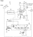
- Figs. 3 and 4 are views illustrating the locked state and the unlocked state of the coupler cylinder in the hydraulic system used in the work machine in Fig. 1 .
- hydraulic system 20 includes a coupler cylinder 21, a main pump 23, a pressure increasing valve 25, a pressure reducing valve 26, a coupler switching valve 27, a changeover switch 28, a pump 29a, a shuttle valve 29b, a controller 30, and a pressure sensor 41.
- Coupler cylinder 21 is driven in either a lock direction P1 or an unlock direction P2.
- Lock direction P1 is a drive direction locking bucket 6 to quick coupler 7.
- Unlock direction P2 is a drive direction unlocking bucket 6 from quick coupler 7.
- bucket 6 is locked when coupler cylinder 21 expands, and bucket 6 is unlocked when coupler cylinder 21 contracts.
- bucket 6 may be locked when coupler cylinder 21 contracts, and bucket 6 may be unlocked when coupler cylinder 21 expands.
- Main pump 23 supplies the hydraulic oil to each of coupler cylinder 21 and a work-implement cylinder (boom cylinder 18, bucket cylinder 19 in Fig. 1 ). Coupler cylinder 21 and work-implement cylinders 18, 19 are connected in parallel to main pump 23.
- main pump 23 is a variable discharge pressure oil pump.
- a capacity of the hydraulic oil supplied from main pump 23 can be adjusted by changing an inclination angle of swash plate 23a.
- the inclination angle of swash plate 23a is changed by a capacity control valve (not illustrated).
- Pump 29a supplies pilot oil to each of coupler cylinder 21 and main valve 24a.
- the oil supplied to cylinders 21, 18, 19 in order to operate coupler cylinder 21 and work-implement cylinders 18, 19 is referred to as the hydraulic oil.
- the oil supplied to hold the locked state or the unlocked state of coupler cylinder 21 or to drive the spool of main valve 24a is referred to as the pilot oil.
- the pressure of the pilot oil is referred to as pilot pressure (PPC pressure).
- the hydraulic oil is oil having pressure of 30 MPa
- the pilot oil is oil having pressure (pilot oil pressure) of 3 MPa.
- the pressure of the hydraulic oil is different from the pilot oil pressure and is higher than the pilot oil pressure.
- Pressure increasing valve 25 increases (pressure-increases) or decreases (pressure-reduces) the pressure of the hydraulic oil supplied to coupler cylinder 21.
- Pressure increasing valve 25 includes main valve 24a and an electromagnetic switching valve (solenoid valve) 24b.
- Main valve 24a is connected to main pump 23 through hydraulic piping. Main valve 24a sends the hydraulic oil supplied from main pump 23 to coupler cylinder 21.
- the pilot oil is supplied from pump 29a to electromagnetic switching valve 24b.
- Electromagnetic switching valve 24b is electrically connected to controller 30.
- electromagnetic switching valve 24b receives a current instruction from controller 30.
- Electromagnetic switching valve 24b generates pilot pressure according to the current value of the current instruction. Electromagnetic switching valve 24b drives the spool of main valve 24a by the pilot pressure. An amount of hydraulic oil sent from main valve 24a to coupler cylinder 21 changes when the spool of main valve 24a is driven.
- a supply start and a supply stop of the hydraulic oil to coupler cylinder 21 can be controlled.
- the increase (pressure increase) and the decrease (pressure reduction) of the hydraulic pressure of the hydraulic oil supplied to coupler cylinder 21 can be controlled.
- Pressure reducing valve 26 is connected to main valve 24a and coupler switching valve 27 through hydraulic piping.
- pressure reducing valve 26 reduces the hydraulic pressure to a predetermined value.
- pressure reducing valve 26 does not adjust the hydraulic pressure when the hydraulic pressure of the hydraulic oil supplied from main pump 23 is less than or equal to a predetermined value.
- Coupler switching valve 27 is connected to pressure reducing valve 26 and coupler cylinder 21 through hydraulic piping. Coupler switching valve 27 is electrically connected to controller 30. Coupler switching valve 27 can switch between a lock-side position R1 and an unlock-side position R2 in response to an electric instruction from controller 30.
- Lock-side position R1 is a position where the hydraulic oil from main pump 23 is supplied to coupler cylinder 21 such that coupler cylinder 21 is driven in lock direction P1. Specifically, when coupler switching valve 27 is at lock-side position R1, the hydraulic oil from main pump 23 is supplied to bottom side 21B of coupler cylinder 21.
- Unlock-side position R2 is a position where the hydraulic oil from main pump 23 is supplied to coupler cylinder 21 such that coupler cylinder 21 is driven in unlock direction P2. Specifically, when coupler switching valve 27 is at unlock-side position R2, the hydraulic oil from main pump 23 is supplied to head side 21H of coupler cylinder 21.
- changeover switch 28 The position of coupler switching valve 27 is switched by changeover switch 28.
- Changeover switch 28 is electrically connected to controller 30.
- Changeover switch 28 includes a lever, a dial, and the like that can be switched between at least two positions of a lock position and an unlock position.
- changeover switch 28 is a seesaw switch, but is not limited thereto.
- Controller 30 receives an electric signal representing either the locked position or the unlocked position of changeover switch 28 from changeover switch 28. Controller 30 issues the electric instruction for switching between lock-side position R1 and unlock-side position R2 to coupler switching valve 27 based on the electric signal indicating the position.
- Shuttle valve 29b has two inlets and a common outlet, and the outlet is automatically connected to either one of the inlets by action of inlet pressure.
- shuttle valve 29b selectively supplies only one of the hydraulic oil supplied from main pump 23 and the pilot oil supplied from pump 29a to coupler cylinder 21.
- Pressure sensor 41 is provided in an oil passage between main pump 23 and coupler cylinder 21.
- the hydraulic pressure (pressure) in the oil passage between main pump 23 and coupler cylinder 21 is detected by pressure sensor 41.
- pressure sensor 41 is provided in the oil passage between main pump 23 and main valve 24a.
- Pressure sensor 41 is electrically connected to controller 30. Thus, the pressure detected by pressure sensor 41 is input to controller 30 as the electric signal. Controller 30 instructs electromagnetic switching valve 24b of pressure increasing valve 25 to stop the supply of the oil (for example, the hydraulic oil) to coupler cylinder 21 based on the electric signal indicating pressure.
- the oil for example, the hydraulic oil
- coupler switching valve 27 is switched to lock-side position R1 in response to the electric instruction from controller 30 as illustrated in Fig. 3 .
- the hydraulic oil or the pilot oil is supplied to bottom side 21B of coupler cylinder 21.
- coupler switching valve 27 is switched to unlock-side position R2 in response to the electric instruction from controller 30 as illustrated in Fig. 4 .
- the hydraulic oil or the pilot oil is supplied to head side 21H of coupler cylinder 21.
- the hydraulic system in the embodiment is an alternate system.
- the alternate system is a system that increases the pressure of coupler cylinder 21 by inputting a signal of changeover switch 28 to pressure increasing valve 25 through controller 30.
- changeover switch 28 when once changeover switch 28 is switched to the lock position or the unlock position, changeover switch 28 maintains the state even when the operator releases a hand from changeover switch 28.
- Changeover switch 28 that maintains the state even when the operator releases the hand in this manner is referred to as an "alternate switch" in the present specification.
- controller 30 determines whether coupler cylinder 21 reaches the stroke end. Specifically, controller 30 considers that coupler cylinder 21 reaches the stroke end when the pressure detected by pressure sensor 41 becomes higher than a predetermined pressure, and instructs pressure increasing valve 25 to stop the supply of the oil (for example, hydraulic oil) to coupler cylinder 21.
- oil for example, hydraulic oil
- controller 30 With reference to Fig. 5 , a functional block of controller 30 will be described below.
- Fig. 5 is a view illustrating a functional block of the controller used in the work machine of Fig. 1 .
- controller 30 includes a switch signal acquisition unit 31, a switch signal determination unit 32, a pressure signal acquisition unit 33, a pressure signal determination unit 34, and a valve controller 35.
- Switch signal acquisition unit 31 acquires an electric signal indicating either the lock position or the unlock position of changeover switch 28.
- Switch signal determination unit 32 determines whether changeover switch 28 is at the lock position or the unlock position based on the signal acquired by switch signal acquisition unit 31.
- Switch signal determination unit 32 outputs a position signal of the lock position or the unlock position to valve controller 35.
- Valve controller 35 drives and controls coupler switching valve 27 based on the received position signal.
- valve controller 35 controls coupler switching valve 27 such that coupler switching valve 27 is switched to lock-side position R1.
- valve controller 35 instructs pressure increasing valve 25 to start the supply of the hydraulic oil to coupler cylinder 21. By this instruction, the hydraulic oil is supplied to bottom side 21B of coupler cylinder 21. Thus, coupler cylinder 21 is driven in lock direction P1 and enters the locked state.
- valve controller 35 When valve controller 35 receives the signal of the unlock position, valve controller 35 controls coupler switching valve 27 such that coupler switching valve 27 is switched to unlock-side position R2. When valve controller 35 receives the signal of the unlock position, valve controller 35 instructs pressure increasing valve 25 to start the supply of the hydraulic oil to coupler cylinder 21. By this instruction, the hydraulic oil is supplied to head side 21H of coupler cylinder 21. Thus, coupler cylinder 21 is driven in unlock direction P2, and coupler cylinder 21 becomes the unlocked state.
- Pressure signal acquisition unit 33 acquires the electric signal indicating the pressure detected by pressure sensor 41.
- Pressure signal determination unit 34 determines the pressure value based on the signal acquired by pressure signal acquisition unit 33. Specifically, pressure signal determination unit 34 determines whether the hydraulic pressure acquired by pressure signal acquisition unit 33 is greater than a predetermined pressure. The predetermined pressure is stored in a storage 40.
- the predetermined pressure is set to be larger than the pilot pressure.
- the predetermined pressure may be changed by a temperature.
- the predetermined pressure may be set to be less than relief pressure in the relief valve of coupler cylinder 21.
- pressure sensor 41 is disposed near main pump 23, sometimes the predetermined pressure is higher than the relief pressure.
- Pressure signal determination unit 34 outputs the signal indicating the determination result as to whether the hydraulic pressure acquired by pressure signal acquisition unit 33 is higher than the predetermined pressure to the valve controller 35.
- Valve controller 35 drives and controls pressure increasing valve 25 based on the received signal of the determination result.
- valve controller 35 receives the determination result that the pressure detected by pressure sensor 41 is higher than the predetermined pressure
- valve controller 35 controls pressure increasing valve 25 such that the supply of the hydraulic oil to coupler cylinder 21 is stopped.
- electromagnetic switching valve 24b receiving the instruction from valve controller 35 drives and controls the spool of main valve 24a, thereby stopping the supply of the hydraulic oil to coupler cylinder 21.
- valve controller 35 When valve controller 35 receives the determination result that the pressure detected by pressure sensor 41 is less than or equal to the predetermined pressure, valve controller 35 controls pressure increasing valve 25 to continue the supply of the hydraulic oil to coupler cylinder 21.
- Controller 30 and storage 40 may be mounted on work machine 1 ( Fig. 1 ) or may be disposed outside work machine 1. When being separately disposed outside work machine 1, controller 30 and storage 40 may be wirelessly connected to work machine 1 (pressure sensor 41, changeover switch 28, coupler switching valve 27, pressure increasing valve 25) or the like.
- controller 30 is a processor, and may be a central processing unit (CPU).
- Storage 40 may be connected to controller 30 in a wired (electric wiring or the like) manner or in a wireless manner. Storage 40 may be included in controller 30.
- a method for controlling the hydraulic system 20 of the embodiment in Figs. 3 and 4 will be described below.
- a control method in the case where bucket 6 is switched from the unlocked state ( Fig. 4 ) to the locked state ( Fig. 3 ) will be described as an example.
- Fig. 6 is a flowchart illustrating an example of the method for controlling the hydraulic system used in the work machine of Fig. 1 .
- Fig. 7 is a view illustrating a control chart of a changeover switch (A), a coupler switching electromagnetic switching valve (B), a pressure increasing electromagnetic switching valve (C), and a pressure sensor (D) when the unlocked state is switched to the locked state.
- A changeover switch
- B coupler switching electromagnetic switching valve
- C pressure increasing electromagnetic switching valve
- D pressure sensor
- hydraulic system 20 is in the unlocked state illustrated in Fig. 4 .
- changeover switch 28 is at the unlock position as illustrated in Fig. 7(A) .
- coupler switching valve 27 is located at unlock-side position R2 ( Fig. 4 ) when an on-signal is input.
- electromagnetic switching valve 24b does not supply the hydraulic oil from main pump 23 to coupler cylinder 21 when an off-signal is input as illustrated in Fig. 7(C) .
- the pressure detected by pressure sensor 41 becomes zero as illustrated in Fig. 7(D) .
- the pilot oil is supplied from pump 29a to coupler cylinder 21. For this reason, head side 21H of coupler cylinder 21 becomes the pilot pressure. The unlocked state of coupler cylinder 21 is held (held) by the pilot pressure.
- changeover switch 28 is switched from the unlock position to the lock position.
- the electric signal indicating the switching to the lock position in changeover switch 28 is input to switch signal determination unit 32 of controller 30 (step S1).
- controller 30 receives a supply instruction of hydraulic oil to coupler cylinder 21 from changeover switch 28.
- switch signal determination unit 32 determines that changeover switch 28 is in the lock position, and outputs the position signal of the lock position to valve controller 35.
- Valve controller 35 drives and controls coupler switching valve 27 and pressure increasing valve 25 based on the received position signal (step S2). Specifically, as illustrated in Fig. 7(B) , valve controller 35 outputs the off-signal (a switching signal to lock-side position R1) to coupler switching valve 27. That is, valve controller 35 instructs coupler switching valve 27 to switch from unlock-side position R2 to lock-side position R1. Thus, coupler switching valve 27 is switched from unlock-side position R2 ( Fig. 4 ) to lock-side position R1 ( Fig. 3 ).
- valve controller 35 outputs the on-signal (a supply start signal of the hydraulic oil to coupler cylinder 21) to electromagnetic switching valve 24b of pressure increasing valve 25. That is, valve controller 35 instructs pressure increasing valve 25 to start the pressure increase of coupler cylinder 21.
- the spool of main valve 24a is driven by this instruction to start the supply of the hydraulic oil from main pump 23 to coupler cylinder 21 through pressure increasing valve 25.
- the bottom side of coupler cylinder 21 is changed from the non-pressure increasing state to the pressure increasing state, and piston 21b of coupler cylinder 21 is driven in lock direction P1 to start the transition from the unlocked state to the locked state (step S3).
- Pressure sensor 41 detects the pressure in the oil passage from main pump 23 to coupler cylinder 21 (step S4). When the pressure increase of coupler cylinder 21 is started, the pressure detected by pressure sensor 41 gradually increases as illustrated in Fig. 7(D) . Pressure signal determination unit 34 of controller 30 determines whether the increased pressure exceeds the predetermined pressure (step S5).
- valve controller 35 drives and controls pressure increasing valve 25 based on the received signal of the determination result as illustrated in Fig. 5 (step S6).
- valve controller 35 outputs the off-signal (a supply stop signal of the hydraulic oil to coupler cylinder 21) to electromagnetic switching valve 24b of pressure increasing valve 25. That is, valve controller 35 instructs pressure increasing valve 25 to stop the pressure increase of coupler cylinder 21 and to become the non-pressure increase.
- the spool of main valve 24a is driven by this instruction, and the supply of the hydraulic oil from main pump 23 to coupler cylinder 21 is stopped by main valve 24a.
- the pressure detected by pressure sensor 41 becomes zero.
- step S6 the off-signal is output to electromagnetic switching valve 24b after a predetermined time elapses from when it is determined that the pressure detected by pressure sensor 41 exceeds the predetermined pressure. Further, when the off-signal is output to electromagnetic switching valve 24b after a sufficient time elapses after the pressure detected by pressure sensor 41 exceeds the predetermined pressure, coupler cylinder 21 can be reliably caused to reach the stroke end.
- hydraulic system 20 is similarly controlled even when coupler cylinder 21 transfers from the locked state to the unlocked state.
- controller 30 instructs pressure increasing valve 25 to stop the supply of the oil (for example, hydraulic oil) to coupler cylinder 21 based on the pressure in the oil passage between main pump 23 and coupler cylinder 21.
- the oil for example, hydraulic oil
- controller 30 instructs pressure increasing valve 25 to stop the supply of the oil (for example, hydraulic oil) to coupler cylinder 21 based on the pressure in the oil passage between main pump 23 and coupler cylinder 21.
- controller 30 instructs pressure increasing valve 25 to stop the supply of the oil (for example, hydraulic oil) to coupler cylinder 21 based on the pressure in the oil passage between main pump 23 and coupler cylinder 21.
- the locked state of coupler cylinder 21 can be reliably detected. Consequently, a lock failure due to an abnormality of main pump 23, an operation failure of valves 25, 27, or the like can be prevented.
- the hydraulic system for the work machine, the work machine, and the method of controlling the hydraulic system which have good fuel efficiency and can prevent erroneous recognition of the locked state, can be implemented according to the embodiment.
- controller 30 instructs pressure increasing valve 25 to start the supply of the oil (for example, hydraulic oil) to coupler cylinder 21 based on the supply instruction of the oil (for example, hydraulic oil) to coupler cylinder 21.
- oil for example, hydraulic oil
- controller 30 This allows controller 30 to control the supply of oil.
- the oil supply instruction is based on the operation of the alternate switch.
- changeover switch 28 maintains the state even when the operator releases the hand from changeover switch 28.
- controller 30 stops the supply of the oil (for example, hydraulic oil) to coupler cylinder 21 at a time point when the pressure detected by pressure sensor 41 reaches a predetermined pressure.
- the predetermined pressure is set to be larger than the pilot pressure.
- pilot pressure is used to hold the locked state or the unlocked state of coupler cylinder 21.
- the predetermined pressure is set to be larger than the pilot pressure, the non-pressure increasing state holding the locked state or the unlocked state can be clearly distinguished from the pressure increasing state.
- hydraulic system 20 includes coupler switching valve 27 that switches between the locked state and the unlocked state of coupler cylinder 21.
- coupler cylinder 21 can be switched between the locked state and the unlocked state.
- hydraulic system 20 includes pressure sensor 41 that detects the pressure in the oil passage between main pump 23 and coupler cylinder 21.
- the locked state of coupler cylinder 21 can be reliably detected by detecting the pressure by pressure sensor 41. Consequently, a lock failure due to the abnormality of main pump 23, an operation failure of valves 25, 27, or the like can be prevented.
- pressure sensor 41 is provided so as to be able to detect the pressure between main pump 23 and pressure increasing valve 25 .
- the pressure sensor 41 may be disposed so as to be able to detect the hydraulic pressure (pressure) between coupler switching valve 27 and coupler cylinder 21 as illustrated in Fig. 8 .
- Pressure sensor 41 may be disposed so as to be able to measure the pressure in main pump 23, and measure the pressure in coupler cylinder 21.
Landscapes
- Engineering & Computer Science (AREA)
- General Engineering & Computer Science (AREA)
- Mechanical Engineering (AREA)
- Mining & Mineral Resources (AREA)
- Civil Engineering (AREA)
- Structural Engineering (AREA)
- Physics & Mathematics (AREA)
- Fluid Mechanics (AREA)
- Operation Control Of Excavators (AREA)
- Fluid-Pressure Circuits (AREA)
Abstract
Description
- The present disclosure relates to a hydraulic system for a work machine, the work machine, and a method for controlling the hydraulic system.
- Conventionally, there is known a work machine in which a quick coupler capable of attaching and detaching various attachments is provided at a distal end of a work implement. The quick coupler includes a quick coupler cylinder. The quick coupler cylinder locks or unlocks the attachment by expanding and contracting with supply of hydraulic oil.
- At this point,
Japanese Patent Laying-Open No. 2012-2034 - PTL 1:
Japanese Patent Laying-Open No. 2012-2034 - However, in the technique described in
PTL 1, the supply of the hydraulic oil is terminated by time management. For this reason, when an abnormality exists in a quick coupler switching circuit, there is a risk that it is erroneously recognized that the attachment is locked because a predetermined time elapses even though the attachment is not locked. In this case, dropout of the attachment or the like is generated. - An object of the present disclosure is to provide a hydraulic system for a work machine, the work machine, and a method for controlling the hydraulic system, which have good fuel efficiency and can prevent erroneous recognition of a locked state.
- A hydraulic system for a work machine of the present disclosure includes a coupler cylinder, a hydraulic pump, a valve, and a controller. The coupler cylinder is driven between an extended position and a retracted position by being supplied with oil. The hydraulic pump supplies the oil to the coupler cylinder in order to drive the coupler cylinder between the extended position and the retracted position. The valve controls the supply of the oil to the coupler cylinder. The controller controls drive of the valve. The controller instructs the valve to stop the supply of the oil to the coupler cylinder based on pressure in an oil passage between the hydraulic pump and the coupler cylinder.
- A work machine of the present disclosure includes a machine body, an attachment, a coupler cylinder, a hydraulic pump, a valve, and a controller. The attachment can be switched between a locked state and an unlocked state with respect to the machine body. The coupler cylinder is driven between the locked state and the unlocked state of the attachment by being supplied with oil. The hydraulic pump supplies the oil to the coupler cylinder. The valve controls the supply of the oil to the coupler cylinder. The controller controls drive of the valve. The controller instructs the valve to stop the supply of the oil to the coupler cylinder based on pressure in an oil passage between the hydraulic pump and the coupler cylinder.
- A method for controlling a hydraulic system of the present disclosure is a method for controlling a hydraulic system in a work machine including a coupler cylinder, a hydraulic pump, and a valve. The coupler cylinder is driven between an extended position and a retracted position by being supplied with oil. The hydraulic pump supplies the oil to the coupler cylinder in order to drive the coupler cylinder between the extended position and the retracted position. The valve controls the supply of the oil to the coupler cylinder. A method for controlling a hydraulic system includes the following steps.
- Pressure in an oil passage between the hydraulic pump and the coupler cylinder is detected. A supply stop signal of the oil to the coupler cylinder to the valve is outputted based on the detected pressure.
- The hydraulic system for the work machine, the work machine, and the method for controlling the hydraulic system, which have good fuel efficiency and can suppress erroneous recognition of a locked state, can be implemented according to the present disclosure.
-
-
Fig. 1 is a side view illustrating a configuration of a wheel loader as an example of a work machine according to an embodiment of the present disclosure. -
Fig. 2 is a sectional view taken along a line II-II inFig. 1 , and illustrates a state in which a coupler cylinder is driven between an unlocked state (A) and a locked state (B) in the work machine. -
Fig. 3 is a view illustrating the locked state of the coupler cylinder in a hydraulic system used in the work machine ofFig. 1 . -
Fig. 4 is a view illustrating the unlocked state of the coupler cylinder in the hydraulic system used in the work machine ofFig. 1 . -
Fig. 5 is a view illustrating a functional block of a controller used in the work machine ofFig. 1 . -
Fig. 6 is a flowchart illustrating an example of a method for controlling the hydraulic system used in the work machine ofFig. 1 . -
Fig. 7 is a view illustrating a control chart of a changeover switch (A), a coupler switching valve (B), an electromagnetic switching valve (C), and a pressure sensor (D) when the unlocked state is switched to the locked state. -
Fig. 8 is a view illustrating the locked state of the coupler cylinder in a modification of the hydraulic system. - With reference to the drawings, an embodiment of the present disclosure will be described in detail below. In the specification and the drawings, the same components or corresponding components are denoted by the same reference numerals, and redundant description will not be repeated. In the drawings, the configuration may be omitted or simplified for convenience of description. In addition, at least a part of the embodiment and a modification may be arbitrarily combined with each other.
- With reference to
Fig. 1 , a configuration of a wheel loader as an example of a work machine according to an embodiment will be described. The work machine of the embodiment is not limited to the wheel loader. The work machine of the embodiment may be a work machine on which a quick coupler is mounted, and may be a hydraulic excavator, a bulldozer, a motor grader, or the like. -
Fig. 1 is a side view illustrating a configuration of the work machine (wheel loader) according to the embodiment of the present disclosure. Awheel loader 1 includes avehicle body frame 2, a work implement 3, atraveling device 4, and acab 5. -
Vehicle body frame 2 includes afront frame 11 and arear frame 12.Front frame 11 is attached towork implement 3. An engine (not illustrated) or the like is mounted onrear frame 12. - A
steering cylinder 13 is attached tofront frame 11 andrear frame 12. -
Steering cylinder 13 is a hydraulic cylinder that expands and contracts by supply of hydraulic oil.Front frame 11 andrear frame 12 are swingable in a right-left direction by the extension and the contraction ofsteering cylinder 13. - Traveling
device 4 includes afront traveling wheel 4a and arear traveling wheel 4b. When each offront traveling wheel 4a andrear traveling wheel 4b is rotationally driven,wheel loader 1 self-travels.Cab 5 is placed onvehicle body frame 2.Cab 5 is disposed behind work implement 3. A seat on which an operator sits, an operating device, and the like are disposed incab 5. - Work implement 3 is attached to a front of
front frame 11. Work implement 3 includes abucket 6, aquick coupler 7, aboom 14, abell crank 16, atilt rod 17, aboom cylinder 18, and abucket cylinder 19. -
Bucket 6 is one aspect of the attachment. The attachment is not limited tobucket 6, but may be another aspect such as a fork or a breaker. - A base end of
boom 14 is rotatably attached tofront frame 11.Bucket 6 is rotatably attached to the distal end ofboom 14 withquick coupler 7 interposed therebetween. -
Boom cylinder 18drives boom 14. One end ofboom cylinder 18 is rotatably attached tofront frame 11. The other end ofboom cylinder 18 is rotatably attached toboom 14. - For example,
boom cylinder 18 is a hydraulic cylinder.Boom cylinder 18 is expanded and contracted by the hydraulic oil from a main pump 23 (Figs. 3 and4 ). Thus,boom 14 is driven, andbucket 6 attached to the distal end ofboom 14 moves up and down. - One end of
bell crank 16 is connected tofront frame 11 withbucket cylinder 19 interposed therebetween. The other end ofbell crank 16 is connected toquick coupler 7 withtilt rod 17 interposed therebetween.Quick coupler 7 is rotatable with respect to boom 14 together withbucket 6. - One end of
bucket cylinder 19 is rotatably attached tofront frame 11. The other end ofbucket cylinder 19 is rotatably attached to bell crank 16. For example,bucket cylinder 19 is a hydraulic cylinder.Bucket cylinder 19 is expanded and contracted by the hydraulic oil from main pump 23 (Figs. 3 and4 ). Thus,bucket 6 is driven, andbucket 6 rotates up and down with respect toboom 14. -
Quick coupler 7 includes aframe 7a and a connectingpin 7c.Frame 7a includes a through-hole 7b. Through-hole 7b penetratesframe 7a in the right-left direction. Connectingpin 7c is fixed to frame 7a and extends in the right-left direction. -
Quick coupler 7 includes a coupler cylinder (not illustrated). The coupler cylinder is a hydraulic cylinder that expands and contracts by supply of oil. A fixingpin 22 is attached to a distal end of a piston rod of the coupler cylinder. -
Bucket 6 includes abracket 6a at the rear end.Bracket 6a includes a through-hole 6b. Through-hole 6b penetratesbracket 6a in the right-left direction. Ahook 6c is provided at an upper end ofbracket 6a. - When
bucket 6 is attached toquick coupler 7, first, hook 6c ofbucket 6 is hooked on connectingpin 7c ofquick coupler 7. Thereafter, fixingpin 22 attached to the coupler cylinder is inserted into both through-hole 6b ofbucket 6 and through-hole 7b ofquick coupler 7. - <Unlocked state and locked state of
coupler cylinder 21> - With reference to
Fig. 2 , an unlocked state and a locked state of acoupler cylinder 21 will be described below. -
Fig. 2 is a sectional view taken along a line II-II inFig. 1 , and illustrates a state in which a coupler cylinder is driven between an unlocked state (A) and a locked state (B) in the work machine. - As illustrated in
Fig. 2(A) ,quick coupler 7 includescoupler cylinder 21.Coupler cylinder 21 includes acylinder tube 21a, apiston 21b, and apiston rod 21c. -
Cylinder tube 21a has a cylindrical shape.Piston 21b is slidably disposed insidecylinder tube 21a.Piston rod 21c is connected topiston 21b at one end, and protrudes to an outside ofcylinder tube 21a at the other end. Fixingpin 22 is connected to the other end ofpiston rod 21c protruding to the outside ofcylinder tube 21a. - Oil can be supplied to and discharged from a
head side 21H and abottom side 21B ofpiston 21b insidecylinder tube 21a.Head side 21H ofpiston 21b means a side ofpiston rod 21c with respect topiston 21b.Bottom side 21B ofpiston 21b means a side opposite tohead side 21H with respect topiston 21b. - Through-
hole 7b made inframe 7a ofquick coupler 7 is located on an extension line in an extending and contracting direction ofcoupler cylinder 21. Through-hole 7b has a size into which fixingpin 22 can be inserted. Through-hole 6b provided inbracket 6a ofbucket 6 also has a size into which fixingpin 22 can be inserted. - When
bucket 6 is attached toquick coupler 7, first, hook 6c ofbucket 6 is hooked on connectingpin 7c ofquick coupler 7. Thereafter, through-hole 6b ofbucket 6 is located on the extension line of the extending and contracting direction ofcoupler cylinder 21. In this state,bucket 6 is not yet locked toquick coupler 7, but is in the unlocked state. - From this unlocked state, the hydraulic oil is supplied to
bottom side 21B ofcoupler cylinder 21. Thus,piston 21b moves to headside 21H. Fixingpin 22 also moves along with the movement ofpiston 21b. - As illustrated in
Fig. 2(B) , fixingpin 22 is inserted into both through-hole 6b and through-hole 7b by the movement of fixingpin 22. Thus,bucket 6 is locked toquick coupler 7 and becomes the locked state. - In the embodiment, the locked state refers to a state in which
coupler cylinder 21 is fixed at the extended position and the cylinder pressure (pressure onbottom side 21B) is a pressure greater than or equal to a predetermined value (for example, pressure greater than or equal to pilot pressure). Furthermore, in the embodiment, the unlocked state refers to a state in whichcoupler cylinder 21 is retracted, and refers to a state in which cylinder pressure (pressure onhead side 21H) is a pressure greater than or equal to a predetermined value (for example, pressure greater than or equal to the pilot pressure). The pilot pressure will be described later. - The state in which
coupler cylinder 21 is fixed at the retracted position and the cylinder pressure (the pressure onhead side 21H) is a pressure greater than or equal to a predetermined value (for example, the pressure greater than or equal to the pilot pressure) may be set to the locked state. In addition, the state in whichcoupler cylinder 21 is fixed at the extended position and the cylinder pressure (the pressure onbottom side 21B) is a pressure greater than or equal to a predetermined value (for example, the pressure greater than or equal to the pilot pressure) may be set to the unlocked state. - When
bucket 6 is transferred from the locked state to the unlocked state, the hydraulic oil is supplied to headside 21H ofcoupler cylinder 21. Thus,piston 21b moves tobottom side 21B. Fixingpin 22 also moves along with the movement ofpiston 21b. - As illustrated in
Fig. 2(A) , fixingpin 22 is pulled out from both through-hole 6b and through-hole 7b by the movement of fixingpin 22. Thus, the locked state ofbucket 6 with respect toquick coupler 7 is released, andbucket 6 becomes the unlocked state. - With reference to
Figs. 3 and4 ,hydraulic system 20 that drives and controlscoupler cylinder 21 will be described below. -
Figs. 3 and4 are views illustrating the locked state and the unlocked state of the coupler cylinder in the hydraulic system used in the work machine inFig. 1 . - As illustrated in
Fig. 3 ,hydraulic system 20 includes acoupler cylinder 21, amain pump 23, apressure increasing valve 25, apressure reducing valve 26, acoupler switching valve 27, achangeover switch 28, apump 29a, ashuttle valve 29b, acontroller 30, and apressure sensor 41. -
Coupler cylinder 21 is driven in either a lock direction P1 or an unlock direction P2. Lock direction P1 is a drivedirection locking bucket 6 toquick coupler 7. Unlock direction P2 is a drivedirection unlocking bucket 6 fromquick coupler 7. - In the embodiment,
bucket 6 is locked whencoupler cylinder 21 expands, andbucket 6 is unlocked whencoupler cylinder 21 contracts. However,bucket 6 may be locked whencoupler cylinder 21 contracts, andbucket 6 may be unlocked whencoupler cylinder 21 expands. - Each of
main pump 23 andpump 29a is driven by an engine (not illustrated).Main pump 23 supplies the hydraulic oil to each ofcoupler cylinder 21 and a work-implement cylinder (boom cylinder 18,bucket cylinder 19 inFig. 1 ).Coupler cylinder 21 and work-implementcylinders main pump 23. - For example,
main pump 23 is a variable discharge pressure oil pump. A capacity of the hydraulic oil supplied frommain pump 23 can be adjusted by changing an inclination angle ofswash plate 23a. The inclination angle ofswash plate 23a is changed by a capacity control valve (not illustrated). -
Pump 29a supplies pilot oil to each ofcoupler cylinder 21 andmain valve 24a. - In the present specification, the oil supplied to
cylinders coupler cylinder 21 and work-implementcylinders coupler cylinder 21 or to drive the spool ofmain valve 24a is referred to as the pilot oil. The pressure of the pilot oil is referred to as pilot pressure (PPC pressure). For example, the hydraulic oil is oil having pressure of 30 MPa, and the pilot oil is oil having pressure (pilot oil pressure) of 3 MPa. The pressure of the hydraulic oil is different from the pilot oil pressure and is higher than the pilot oil pressure. -
Pressure increasing valve 25 increases (pressure-increases) or decreases (pressure-reduces) the pressure of the hydraulic oil supplied tocoupler cylinder 21.Pressure increasing valve 25 includesmain valve 24a and an electromagnetic switching valve (solenoid valve) 24b. -
Main valve 24a is connected tomain pump 23 through hydraulic piping.Main valve 24a sends the hydraulic oil supplied frommain pump 23 tocoupler cylinder 21. - The pilot oil is supplied from
pump 29a toelectromagnetic switching valve 24b.Electromagnetic switching valve 24b is electrically connected tocontroller 30. Thus,electromagnetic switching valve 24b receives a current instruction fromcontroller 30. -
Electromagnetic switching valve 24b generates pilot pressure according to the current value of the current instruction.Electromagnetic switching valve 24b drives the spool ofmain valve 24a by the pilot pressure. An amount of hydraulic oil sent frommain valve 24a tocoupler cylinder 21 changes when the spool ofmain valve 24a is driven. - Thus, a supply start and a supply stop of the hydraulic oil to
coupler cylinder 21 can be controlled. In addition, the increase (pressure increase) and the decrease (pressure reduction) of the hydraulic pressure of the hydraulic oil supplied tocoupler cylinder 21 can be controlled. -
Pressure reducing valve 26 is connected tomain valve 24a andcoupler switching valve 27 through hydraulic piping. When the hydraulic pressure of the hydraulic oil supplied frommain pump 23 is greater than a predetermined value,pressure reducing valve 26 reduces the hydraulic pressure to a predetermined value. Thus, application of the excessive hydraulic pressure tocoupler cylinder 21 is prevented.Pressure reducing valve 26 does not adjust the hydraulic pressure when the hydraulic pressure of the hydraulic oil supplied frommain pump 23 is less than or equal to a predetermined value. -
Coupler switching valve 27 is connected to pressure reducingvalve 26 andcoupler cylinder 21 through hydraulic piping.Coupler switching valve 27 is electrically connected tocontroller 30.Coupler switching valve 27 can switch between a lock-side position R1 and an unlock-side position R2 in response to an electric instruction fromcontroller 30. - Lock-side position R1 is a position where the hydraulic oil from
main pump 23 is supplied tocoupler cylinder 21 such thatcoupler cylinder 21 is driven in lock direction P1. Specifically, whencoupler switching valve 27 is at lock-side position R1, the hydraulic oil frommain pump 23 is supplied tobottom side 21B ofcoupler cylinder 21. - Unlock-side position R2 is a position where the hydraulic oil from
main pump 23 is supplied tocoupler cylinder 21 such thatcoupler cylinder 21 is driven in unlock direction P2. Specifically, whencoupler switching valve 27 is at unlock-side position R2, the hydraulic oil frommain pump 23 is supplied to headside 21H ofcoupler cylinder 21. - The position of
coupler switching valve 27 is switched bychangeover switch 28.Changeover switch 28 is electrically connected tocontroller 30.Changeover switch 28 includes a lever, a dial, and the like that can be switched between at least two positions of a lock position and an unlock position. For example,changeover switch 28 is a seesaw switch, but is not limited thereto. -
Controller 30 receives an electric signal representing either the locked position or the unlocked position of changeover switch 28 fromchangeover switch 28.Controller 30 issues the electric instruction for switching between lock-side position R1 and unlock-side position R2 to coupler switchingvalve 27 based on the electric signal indicating the position. -
Shuttle valve 29b has two inlets and a common outlet, and the outlet is automatically connected to either one of the inlets by action of inlet pressure. Thus,shuttle valve 29b selectively supplies only one of the hydraulic oil supplied frommain pump 23 and the pilot oil supplied frompump 29a tocoupler cylinder 21. - Specifically, when the pressure of the hydraulic oil acting on
shuttle valve 29b is greater than the pressure of the pilot oil acting onshuttle valve 29b, the hydraulic oil is supplied tocoupler cylinder 21. When the pressure of the hydraulic oil acting onshuttle valve 29b is less than the pressure of the pilot oil acting onshuttle valve 29b, the pilot oil is supplied tocoupler cylinder 21. -
Pressure sensor 41 is provided in an oil passage betweenmain pump 23 andcoupler cylinder 21. Thus, the hydraulic pressure (pressure) in the oil passage betweenmain pump 23 andcoupler cylinder 21 is detected bypressure sensor 41. For example,pressure sensor 41 is provided in the oil passage betweenmain pump 23 andmain valve 24a. -
Pressure sensor 41 is electrically connected tocontroller 30. Thus, the pressure detected bypressure sensor 41 is input tocontroller 30 as the electric signal.Controller 30 instructselectromagnetic switching valve 24b ofpressure increasing valve 25 to stop the supply of the oil (for example, the hydraulic oil) tocoupler cylinder 21 based on the electric signal indicating pressure. - When
bucket 6 is in the locked state inhydraulic system 20,coupler switching valve 27 is switched to lock-side position R1 in response to the electric instruction fromcontroller 30 as illustrated inFig. 3 . Thus, the hydraulic oil or the pilot oil is supplied tobottom side 21B ofcoupler cylinder 21. - On the other hand, when
bucket 6 is in the unlocked state inhydraulic system 20,coupler switching valve 27 is switched to unlock-side position R2 in response to the electric instruction fromcontroller 30 as illustrated inFig. 4 . Thus, the hydraulic oil or the pilot oil is supplied to headside 21H ofcoupler cylinder 21. - The hydraulic system in the embodiment is an alternate system. The alternate system is a system that increases the pressure of
coupler cylinder 21 by inputting a signal ofchangeover switch 28 topressure increasing valve 25 throughcontroller 30. - In the case of the alternate system, when once changeover switch 28 is switched to the lock position or the unlock position,
changeover switch 28 maintains the state even when the operator releases a hand fromchangeover switch 28.Changeover switch 28 that maintains the state even when the operator releases the hand in this manner is referred to as an "alternate switch" in the present specification. - When the pressure of
coupler cylinder 21 is increased based on the operation ofalternate switch 28, the pressure-increased hydraulic oil is continuously supplied tocoupler cylinder 21. In this case, when the pressure increase of the hydraulic oil is not stopped, the hydraulic pressure continues to be relieved in the state wherecoupler cylinder 21 is at a stroke end, and the fuel continues to be wastefully consumed. - Accordingly, in the embodiment, whether
coupler cylinder 21 reaches the stroke end is monitored bypressure sensor 41 andcontroller 30. Specifically,controller 30 considers thatcoupler cylinder 21 reaches the stroke end when the pressure detected bypressure sensor 41 becomes higher than a predetermined pressure, and instructspressure increasing valve 25 to stop the supply of the oil (for example, hydraulic oil) tocoupler cylinder 21. - With reference to
Fig. 5 , a functional block ofcontroller 30 will be described below. -
Fig. 5 is a view illustrating a functional block of the controller used in the work machine ofFig. 1 . As illustrated inFig. 5 ,controller 30 includes a switchsignal acquisition unit 31, a switchsignal determination unit 32, a pressuresignal acquisition unit 33, a pressuresignal determination unit 34, and avalve controller 35. - Switch
signal acquisition unit 31 acquires an electric signal indicating either the lock position or the unlock position ofchangeover switch 28. Switchsignal determination unit 32 determines whether changeover switch 28 is at the lock position or the unlock position based on the signal acquired by switchsignal acquisition unit 31. Switchsignal determination unit 32 outputs a position signal of the lock position or the unlock position tovalve controller 35. -
Valve controller 35 drives and controls coupler switchingvalve 27 based on the received position signal. Whenvalve controller 35 receives the signal of the lock position,valve controller 35 controls coupler switchingvalve 27 such thatcoupler switching valve 27 is switched to lock-side position R1. Whenvalve controller 35 receives the signal of the lock position,valve controller 35 instructspressure increasing valve 25 to start the supply of the hydraulic oil tocoupler cylinder 21. By this instruction, the hydraulic oil is supplied tobottom side 21B ofcoupler cylinder 21. Thus,coupler cylinder 21 is driven in lock direction P1 and enters the locked state. - When
valve controller 35 receives the signal of the unlock position,valve controller 35 controls coupler switchingvalve 27 such thatcoupler switching valve 27 is switched to unlock-side position R2. Whenvalve controller 35 receives the signal of the unlock position,valve controller 35 instructspressure increasing valve 25 to start the supply of the hydraulic oil tocoupler cylinder 21. By this instruction, the hydraulic oil is supplied to headside 21H ofcoupler cylinder 21. Thus,coupler cylinder 21 is driven in unlock direction P2, andcoupler cylinder 21 becomes the unlocked state. - Pressure
signal acquisition unit 33 acquires the electric signal indicating the pressure detected bypressure sensor 41. Pressuresignal determination unit 34 determines the pressure value based on the signal acquired by pressuresignal acquisition unit 33. Specifically, pressuresignal determination unit 34 determines whether the hydraulic pressure acquired by pressuresignal acquisition unit 33 is greater than a predetermined pressure. The predetermined pressure is stored in astorage 40. - For example, the predetermined pressure is set to be larger than the pilot pressure. The predetermined pressure may be changed by a temperature. For example, the predetermined pressure may be set to be less than relief pressure in the relief valve of
coupler cylinder 21. However, whenpressure sensor 41 is disposed nearmain pump 23, sometimes the predetermined pressure is higher than the relief pressure. - Pressure
signal determination unit 34 outputs the signal indicating the determination result as to whether the hydraulic pressure acquired by pressuresignal acquisition unit 33 is higher than the predetermined pressure to thevalve controller 35. -
Valve controller 35 drives and controlspressure increasing valve 25 based on the received signal of the determination result. Whenvalve controller 35 receives the determination result that the pressure detected bypressure sensor 41 is higher than the predetermined pressure,valve controller 35 controlspressure increasing valve 25 such that the supply of the hydraulic oil tocoupler cylinder 21 is stopped. Specifically,electromagnetic switching valve 24b receiving the instruction fromvalve controller 35 drives and controls the spool ofmain valve 24a, thereby stopping the supply of the hydraulic oil tocoupler cylinder 21. - When
valve controller 35 receives the determination result that the pressure detected bypressure sensor 41 is less than or equal to the predetermined pressure,valve controller 35 controlspressure increasing valve 25 to continue the supply of the hydraulic oil tocoupler cylinder 21. -
Controller 30 andstorage 40 may be mounted on work machine 1 (Fig. 1 ) or may be disposed outsidework machine 1. When being separately disposed outsidework machine 1,controller 30 andstorage 40 may be wirelessly connected to work machine 1 (pressure sensor 41,changeover switch 28,coupler switching valve 27, pressure increasing valve 25) or the like. For example,controller 30 is a processor, and may be a central processing unit (CPU). -
Storage 40 may be connected tocontroller 30 in a wired (electric wiring or the like) manner or in a wireless manner.Storage 40 may be included incontroller 30. - With reference to
Figs. 6 and7 , a method for controlling thehydraulic system 20 of the embodiment inFigs. 3 and4 will be described below. Here, a control method in the case wherebucket 6 is switched from the unlocked state (Fig. 4 ) to the locked state (Fig. 3 ) will be described as an example. -
Fig. 6 is a flowchart illustrating an example of the method for controlling the hydraulic system used in the work machine ofFig. 1 .Fig. 7 is a view illustrating a control chart of a changeover switch (A), a coupler switching electromagnetic switching valve (B), a pressure increasing electromagnetic switching valve (C), and a pressure sensor (D) when the unlocked state is switched to the locked state. - First,
hydraulic system 20 is in the unlocked state illustrated inFig. 4 . In the unlocked state after the stop of the pressure increase,changeover switch 28 is at the unlock position as illustrated inFig. 7(A) . As illustrated inFig. 7(B) ,coupler switching valve 27 is located at unlock-side position R2 (Fig. 4 ) when an on-signal is input. In addition,electromagnetic switching valve 24b does not supply the hydraulic oil frommain pump 23 tocoupler cylinder 21 when an off-signal is input as illustrated inFig. 7(C) . Thus, the pressure detected bypressure sensor 41 becomes zero as illustrated inFig. 7(D) . - The pilot oil is supplied from
pump 29a tocoupler cylinder 21. For this reason,head side 21H ofcoupler cylinder 21 becomes the pilot pressure. The unlocked state ofcoupler cylinder 21 is held (held) by the pilot pressure. - As illustrated in
Fig. 7(A) ,changeover switch 28 is switched from the unlock position to the lock position. Thus, as illustrated inFig. 5 , the electric signal indicating the switching to the lock position inchangeover switch 28 is input to switchsignal determination unit 32 of controller 30 (step S1). Specifically,controller 30 receives a supply instruction of hydraulic oil tocoupler cylinder 21 fromchangeover switch 28. Thereafter, switchsignal determination unit 32 determines thatchangeover switch 28 is in the lock position, and outputs the position signal of the lock position tovalve controller 35. -
Valve controller 35 drives and controls coupler switchingvalve 27 andpressure increasing valve 25 based on the received position signal (step S2). Specifically, as illustrated inFig. 7(B) ,valve controller 35 outputs the off-signal (a switching signal to lock-side position R1) tocoupler switching valve 27. That is,valve controller 35 instructscoupler switching valve 27 to switch from unlock-side position R2 to lock-side position R1. Thus,coupler switching valve 27 is switched from unlock-side position R2 (Fig. 4 ) to lock-side position R1 (Fig. 3 ). - In addition, as illustrated in
Fig. 7(C) ,valve controller 35 outputs the on-signal (a supply start signal of the hydraulic oil to coupler cylinder 21) toelectromagnetic switching valve 24b ofpressure increasing valve 25. That is,valve controller 35 instructspressure increasing valve 25 to start the pressure increase ofcoupler cylinder 21. The spool ofmain valve 24a is driven by this instruction to start the supply of the hydraulic oil frommain pump 23 tocoupler cylinder 21 throughpressure increasing valve 25. Thus, the bottom side ofcoupler cylinder 21 is changed from the non-pressure increasing state to the pressure increasing state, andpiston 21b ofcoupler cylinder 21 is driven in lock direction P1 to start the transition from the unlocked state to the locked state (step S3). -
Pressure sensor 41 detects the pressure in the oil passage frommain pump 23 to coupler cylinder 21 (step S4). When the pressure increase ofcoupler cylinder 21 is started, the pressure detected bypressure sensor 41 gradually increases as illustrated inFig. 7(D) . Pressuresignal determination unit 34 ofcontroller 30 determines whether the increased pressure exceeds the predetermined pressure (step S5). - As a result of the above determination, when it is determined that the pressure detected by
pressure sensor 41 does not exceed the predetermined pressure, the determination whether the pressure exceeds the predetermined pressure by pressuresignal determination unit 34 is repeated. - On the other hand, as a result of the determination, when it is determined that the pressure detected by
pressure sensor 41 exceeds the predetermined pressure,valve controller 35 drives and controlspressure increasing valve 25 based on the received signal of the determination result as illustrated inFig. 5 (step S6). - Specifically, as illustrated in
Fig. 7(C) ,valve controller 35 outputs the off-signal (a supply stop signal of the hydraulic oil to coupler cylinder 21) toelectromagnetic switching valve 24b ofpressure increasing valve 25. That is,valve controller 35 instructspressure increasing valve 25 to stop the pressure increase ofcoupler cylinder 21 and to become the non-pressure increase. The spool ofmain valve 24a is driven by this instruction, and the supply of the hydraulic oil frommain pump 23 tocoupler cylinder 21 is stopped bymain valve 24a. Thus, as illustrated inFig. 7(D) , the pressure detected bypressure sensor 41 becomes zero. - In the non-pressure increasing state, the pilot oil is supplied from
pump 29a tocoupler cylinder 21. For this reason,bottom side 21B ofcoupler cylinder 21 becomes the pilot pressure. The locked state ofcoupler cylinder 21 is held (held) by the pilot pressure. - In step S6, as illustrated in
Figs. 7(C) and 7(D) , the off-signal is output toelectromagnetic switching valve 24b after a predetermined time elapses from when it is determined that the pressure detected bypressure sensor 41 exceeds the predetermined pressure. Further, when the off-signal is output toelectromagnetic switching valve 24b after a sufficient time elapses after the pressure detected bypressure sensor 41 exceeds the predetermined pressure,coupler cylinder 21 can be reliably caused to reach the stroke end. - Although the case where
coupler cylinder 21 transfers from the unlocked state to the locked state has been described above,hydraulic system 20 is similarly controlled even whencoupler cylinder 21 transfers from the locked state to the unlocked state. - An advantageous effect of the embodiment will be described below.
- According to the embodiment, as illustrated in
Fig. 3 ,controller 30 instructspressure increasing valve 25 to stop the supply of the oil (for example, hydraulic oil) tocoupler cylinder 21 based on the pressure in the oil passage betweenmain pump 23 andcoupler cylinder 21. Thus, thatcoupler cylinder 21 reaches the stroke end from the pressure of the pressure sensor can be detected to stop the pressure increase of the oil (for example, hydraulic oil). Consequently, fuel can be prevented from being continuously consumed wastefully, and fuel efficiency is improved. - In addition,
controller 30 instructspressure increasing valve 25 to stop the supply of the oil (for example, hydraulic oil) tocoupler cylinder 21 based on the pressure in the oil passage betweenmain pump 23 andcoupler cylinder 21. Thus, the locked state ofcoupler cylinder 21 can be reliably detected. Consequently, a lock failure due to an abnormality ofmain pump 23, an operation failure ofvalves - As described above, the hydraulic system for the work machine, the work machine, and the method of controlling the hydraulic system, which have good fuel efficiency and can prevent erroneous recognition of the locked state, can be implemented according to the embodiment.
- In the embodiment, as illustrated in
Figs. 3 and4 ,controller 30 instructspressure increasing valve 25 to start the supply of the oil (for example, hydraulic oil) tocoupler cylinder 21 based on the supply instruction of the oil (for example, hydraulic oil) tocoupler cylinder 21. - This allows
controller 30 to control the supply of oil. - In the embodiment, as illustrated in
Figs. 3 and4 , the oil supply instruction is based on the operation of the alternate switch. - Thus, when once being switched to the lock position or the unlock position,
changeover switch 28 maintains the state even when the operator releases the hand fromchangeover switch 28. - In the embodiment, as illustrated in
Figs. 7(C) and 7(D) ,controller 30 stops the supply of the oil (for example, hydraulic oil) tocoupler cylinder 21 at a time point when the pressure detected bypressure sensor 41 reaches a predetermined pressure. The predetermined pressure is set to be larger than the pilot pressure. - Sometimes the pilot pressure is used to hold the locked state or the unlocked state of
coupler cylinder 21. In this case, when the predetermined pressure is set to be larger than the pilot pressure, the non-pressure increasing state holding the locked state or the unlocked state can be clearly distinguished from the pressure increasing state. - In the embodiment, as illustrated in
Figs. 3 and4 ,hydraulic system 20 includescoupler switching valve 27 that switches between the locked state and the unlocked state ofcoupler cylinder 21. Thus,coupler cylinder 21 can be switched between the locked state and the unlocked state. - In the embodiment, as illustrated in
Figs. 3 and4 ,hydraulic system 20 includespressure sensor 41 that detects the pressure in the oil passage betweenmain pump 23 andcoupler cylinder 21. - The locked state of
coupler cylinder 21 can be reliably detected by detecting the pressure bypressure sensor 41. Consequently, a lock failure due to the abnormality ofmain pump 23, an operation failure ofvalves - In the embodiment, as illustrated in
Figs. 3 and4 , the configuration in whichpressure sensor 41 is provided so as to be able to detect the pressure betweenmain pump 23 andpressure increasing valve 25 has been described. However, as long aspressure sensor 41 is provided in the oil passage betweenmain pump 23 andcoupler cylinder 21, for example, thepressure sensor 41 may be disposed so as to be able to detect the hydraulic pressure (pressure) betweencoupler switching valve 27 andcoupler cylinder 21 as illustrated inFig. 8 . -
Pressure sensor 41 may be disposed so as to be able to measure the pressure inmain pump 23, and measure the pressure incoupler cylinder 21. - It should be considered that the disclosed embodiment is an example in all respects and not restrictive. The scope of the present invention is defined by not the description above, but the claims, and it is intended that all modifications within the meaning and scope of the claims and their equivalents are included in the present invention.
- 1: work machine (wheel loader), 2: body frame, 3: work implement, 4: traveling device, 4a: front traveling wheel, 4b: rear traveling wheel, 5: cab, 6: bucket, 6a: bracket, 6b, 7b: through-hole, 6c: hook, 7: quick coupler, 7a: frame, 7c: connecting pin, 11: front frame, 12: rear frame, 13: steering cylinder, 14: boom, 16: bell crank, 17: tilt rod, 18: boom cylinder, 19: bucket cylinder, 20: hydraulic system, 21: coupler cylinder, 21B: bottom side, 21H: head side, 21a: cylinder tube, 21b: piston, 21c: piston rod, 22: fixing pin, 23: main pump, 23a: swash plate, 24a: main valve, 24b: electromagnetic switching valve, 25: pressure increasing valve, 26: pressure reducing valve, 27: coupler switching valve, 28: changeover switch, 29a: pump, 29b: shuttle valve, 30: controller, 31: switch signal acquisition unit, 32: switch signal determination unit, 33: pressure signal acquisition unit, 34: pressure signal determination unit, 35: valve controller, 40: storage, 41: pressure sensor
Claims (9)
- A hydraulic system for a work machine comprising:a coupler cylinder that is driven between an extended position and a retracted position by being supplied with oil;a hydraulic pump that supplies the oil to the coupler cylinder in order to drive the coupler cylinder between the extended position and the retracted position;a valve that controls the supply of the oil to the coupler cylinder; anda controller that controls drive of the valve,wherein the controller instructs the valve to stop the supply of the oil to the coupler cylinder based on pressure in an oil passage between the hydraulic pump and the coupler cylinder.
- The hydraulic system for a work machine according to claim 1, wherein oil having a pressure greater than or equal to a predetermined value is supplied to the coupler cylinder while the coupler cylinder is fixed at each of the extended position and the retracted position.
- The hydraulic system for a work machine according to claim 1 or 2, wherein the controller instructs the valve to start the supply of the oil to the coupler cylinder based on an oil supply instruction to the coupler cylinder.
- The hydraulic system for a work machine according to claim 3, wherein the oil supply instruction is based on an operation of an alternate switch.
- The hydraulic system for a work machine according to any one of claims 1 to 4, whereinthe controller stops the supply of the oil to the coupler cylinder at a time point when the pressure in the oil passage between the hydraulic pump and the coupler cylinder reaches a predetermined pressure, andthe predetermined pressure is set to be larger than a pilot pressure.
- The hydraulic system for a work machine according to any one of claims 1 to 5, further comprising a switching valve that switches between the extended position and the retracted position of the coupler cylinder.
- The hydraulic system for a work machine according to any one of claims 1 to 6, further comprising a pressure sensor that detects the pressure in the oil passage between the hydraulic pump and the coupler cylinder.
- A work machine comprising:a machine body;an attachment that is capable of switching between a locked state and an unlocked state with respect to the machine body;a coupler cylinder that is driven between the locked state and the unlocked state of the attachment by being supplied with oil;a hydraulic pump that supplies the oil to the coupler cylinder;a valve that controls the supply of the oil to the coupler cylinder; anda controller that controls drive of the valve,wherein the controller instructs the valve to stop the supply of the oil to the coupler cylinder based on pressure in an oil passage between the hydraulic pump and the coupler cylinder.
- A method for controlling a hydraulic system in a work machine including a coupler cylinder that is driven between an extended position and a retracted position by being supplied with oil, a hydraulic pump that supplies the oil to the coupler cylinder in order to drive the coupler cylinder between the extended position and the retracted position, and a valve that controls the supply of the oil to the coupler cylinder, the method comprising:detecting pressure in an oil passage between the hydraulic pump and the coupler cylinder; andoutputting a supply stop signal of the oil to the coupler cylinder to the valve based on the detected pressure.
Applications Claiming Priority (2)
| Application Number | Priority Date | Filing Date | Title |
|---|---|---|---|
| JP2020044981A JP7402085B2 (en) | 2020-03-16 | 2020-03-16 | Hydraulic system of working machine, control method of working machine and hydraulic system |
| PCT/JP2021/008855 WO2021187181A1 (en) | 2020-03-16 | 2021-03-08 | Hydraulic system for work machine, work machine, and method for controlling hydraulic system |
Publications (3)
| Publication Number | Publication Date |
|---|---|
| EP4105390A1 true EP4105390A1 (en) | 2022-12-21 |
| EP4105390A4 EP4105390A4 (en) | 2024-02-21 |
| EP4105390B1 EP4105390B1 (en) | 2025-11-05 |
Family
ID=77768217
Family Applications (1)
| Application Number | Title | Priority Date | Filing Date |
|---|---|---|---|
| EP21771049.0A Active EP4105390B1 (en) | 2020-03-16 | 2021-03-08 | Hydraulic system for work machine, work machine, and method for controlling hydraulic system |
Country Status (5)
| Country | Link |
|---|---|
| US (1) | US12612757B2 (en) |
| EP (1) | EP4105390B1 (en) |
| JP (1) | JP7402085B2 (en) |
| CN (1) | CN115279977B (en) |
| WO (1) | WO2021187181A1 (en) |
Family Cites Families (17)
| Publication number | Priority date | Publication date | Assignee | Title |
|---|---|---|---|---|
| JP3590318B2 (en) * | 2000-03-09 | 2004-11-17 | 住友建機製造株式会社 | Hydraulic circuit of construction machinery |
| JP3816771B2 (en) * | 2001-09-06 | 2006-08-30 | 日立建機株式会社 | Hydraulic control device for earth pressure pump for pipe propulsion machine |
| US7007466B2 (en) * | 2001-12-21 | 2006-03-07 | Caterpillar Inc. | System and method for controlling hydraulic flow |
| JP2008014468A (en) | 2006-07-10 | 2008-01-24 | Shin Caterpillar Mitsubishi Ltd | Hydraulic control system in working machine |
| JP2009150462A (en) | 2007-12-20 | 2009-07-09 | Caterpillar Japan Ltd | Hydraulic control system for working machine |
| JP5462724B2 (en) | 2010-06-21 | 2014-04-02 | キャタピラー エス エー アール エル | Construction machine quick coupler circuit |
| US9127695B2 (en) * | 2011-08-24 | 2015-09-08 | Clark Equipment Company | Selectable hydraulic flow control circuit |
| US9228314B2 (en) * | 2013-05-08 | 2016-01-05 | Caterpillar Inc. | Quick coupler hydraulic control system |
| WO2015102120A1 (en) * | 2013-12-30 | 2015-07-09 | 볼보 컨스트럭션 이큅먼트 에이비 | Hydraulic control device and construction equipment having same |
| JP6176666B2 (en) * | 2014-04-08 | 2017-08-09 | キャタピラー エス エー アール エル | Control device for quick coupler in work machine |
| DE102015015809A1 (en) * | 2015-12-07 | 2017-06-08 | Liebherr-Hydraulikbagger Gmbh | Valve unit for quick coupler and quick-change system |
| JP6656913B2 (en) * | 2015-12-24 | 2020-03-04 | 株式会社クボタ | Working machine hydraulic system |
| EP3546655B1 (en) * | 2017-02-28 | 2022-07-13 | Komatsu Ltd. | Quick coupler circuit and quick coupler attachment/detachment method |
| EP3604826B1 (en) * | 2017-03-27 | 2023-06-21 | Hitachi Construction Machinery Co., Ltd. | Hydraulic control system for working machine |
| JP6956643B2 (en) * | 2018-01-11 | 2021-11-02 | 日立建機株式会社 | Construction machinery |
| JP6938442B2 (en) * | 2018-06-29 | 2021-09-22 | 株式会社クボタ | Work machine |
| JP7102262B2 (en) * | 2018-06-29 | 2022-07-19 | 株式会社クボタ | Work machine |
-
2020
- 2020-03-16 JP JP2020044981A patent/JP7402085B2/en active Active
-
2021
- 2021-03-08 US US17/911,495 patent/US12612757B2/en active Active
- 2021-03-08 WO PCT/JP2021/008855 patent/WO2021187181A1/en not_active Ceased
- 2021-03-08 CN CN202180021322.2A patent/CN115279977B/en active Active
- 2021-03-08 EP EP21771049.0A patent/EP4105390B1/en active Active
Also Published As
| Publication number | Publication date |
|---|---|
| US12612757B2 (en) | 2026-04-28 |
| EP4105390A4 (en) | 2024-02-21 |
| CN115279977A (en) | 2022-11-01 |
| JP2021147756A (en) | 2021-09-27 |
| CN115279977B (en) | 2024-06-25 |
| EP4105390B1 (en) | 2025-11-05 |
| WO2021187181A1 (en) | 2021-09-23 |
| JP7402085B2 (en) | 2023-12-20 |
| US20230098551A1 (en) | 2023-03-30 |
Similar Documents
| Publication | Publication Date | Title |
|---|---|---|
| CN110073059B (en) | Quick connector circuit and quick connector disassembly method | |
| US10995475B2 (en) | Construction machine | |
| JP5467176B1 (en) | Work vehicle and control method of work vehicle | |
| JP5690410B1 (en) | Work vehicle and control method of work vehicle | |
| US9334623B2 (en) | Implement coupling system for a power machine | |
| KR101832508B1 (en) | Method of operating a control valve assembly for a hydraulic system | |
| EP3129559A1 (en) | Quick coupler control device for working machine | |
| US20200173145A1 (en) | Work Machine Hydraulic Control System | |
| US9903393B2 (en) | Construction machine | |
| JP7297596B2 (en) | Hydraulic system for construction machinery | |
| CN107201757B (en) | Excavator | |
| JP6982561B2 (en) | Construction machinery | |
| EP4105390B1 (en) | Hydraulic system for work machine, work machine, and method for controlling hydraulic system | |
| JP7489794B2 (en) | Notification system for working machine, and control method for working machine and notification system | |
| US20250369205A1 (en) | Work machine and control method for work machine | |
| JP5518040B2 (en) | Idling stop device | |
| JP6936690B2 (en) | Hydraulic excavator drive system | |
| US11408145B2 (en) | Work vehicle and hydraulic control method | |
| EP4345316B1 (en) | Construction machine | |
| KR20260041101A (en) | Working machine | |
| KR20090099653A (en) | Quick Fit of Construction Equipment |
Legal Events
| Date | Code | Title | Description |
|---|---|---|---|
| STAA | Information on the status of an ep patent application or granted ep patent |
Free format text: STATUS: THE INTERNATIONAL PUBLICATION HAS BEEN MADE |
|
| PUAI | Public reference made under article 153(3) epc to a published international application that has entered the european phase |
Free format text: ORIGINAL CODE: 0009012 |
|
| STAA | Information on the status of an ep patent application or granted ep patent |
Free format text: STATUS: REQUEST FOR EXAMINATION WAS MADE |
|
| 17P | Request for examination filed |
Effective date: 20220915 |
|
| AK | Designated contracting states |
Kind code of ref document: A1 Designated state(s): AL AT BE BG CH CY CZ DE DK EE ES FI FR GB GR HR HU IE IS IT LI LT LU LV MC MK MT NL NO PL PT RO RS SE SI SK SM TR |
|
| DAV | Request for validation of the european patent (deleted) | ||
| DAX | Request for extension of the european patent (deleted) | ||
| A4 | Supplementary search report drawn up and despatched |
Effective date: 20240118 |
|
| RIC1 | Information provided on ipc code assigned before grant |
Ipc: F15B 11/08 20060101ALI20240112BHEP Ipc: F15B 11/028 20060101ALI20240112BHEP Ipc: E02F 9/22 20060101AFI20240112BHEP |
|
| GRAP | Despatch of communication of intention to grant a patent |
Free format text: ORIGINAL CODE: EPIDOSNIGR1 |
|
| STAA | Information on the status of an ep patent application or granted ep patent |
Free format text: STATUS: GRANT OF PATENT IS INTENDED |
|
| INTG | Intention to grant announced |
Effective date: 20250627 |
|
| GRAS | Grant fee paid |
Free format text: ORIGINAL CODE: EPIDOSNIGR3 |
|
| GRAA | (expected) grant |
Free format text: ORIGINAL CODE: 0009210 |
|
| STAA | Information on the status of an ep patent application or granted ep patent |
Free format text: STATUS: THE PATENT HAS BEEN GRANTED |
|
| AK | Designated contracting states |
Kind code of ref document: B1 Designated state(s): AL AT BE BG CH CY CZ DE DK EE ES FI FR GB GR HR HU IE IS IT LI LT LU LV MC MK MT NL NO PL PT RO RS SE SI SK SM TR |
|
| REG | Reference to a national code |
Ref country code: CH Ref legal event code: F10 Free format text: ST27 STATUS EVENT CODE: U-0-0-F10-F00 (AS PROVIDED BY THE NATIONAL OFFICE) Effective date: 20251105 Ref country code: GB Ref legal event code: FG4D |
|
| REG | Reference to a national code |
Ref country code: DE Ref legal event code: R096 Ref document number: 602021041829 Country of ref document: DE |
|
| REG | Reference to a national code |
Ref country code: IE Ref legal event code: FG4D |
|
| REG | Reference to a national code |
Ref country code: SE Ref legal event code: TRGR |
|
| REG | Reference to a national code |
Ref country code: NL Ref legal event code: MP Effective date: 20251105 |
|
| PGFP | Annual fee paid to national office [announced via postgrant information from national office to epo] |
Ref country code: SE Payment date: 20260330 Year of fee payment: 6 |
|
| PG25 | Lapsed in a contracting state [announced via postgrant information from national office to epo] |
Ref country code: ES Free format text: LAPSE BECAUSE OF FAILURE TO SUBMIT A TRANSLATION OF THE DESCRIPTION OR TO PAY THE FEE WITHIN THE PRESCRIBED TIME-LIMIT Effective date: 20251105 |
|
| REG | Reference to a national code |
Ref country code: LT Ref legal event code: MG9D |
|
| PG25 | Lapsed in a contracting state [announced via postgrant information from national office to epo] |
Ref country code: NO Free format text: LAPSE BECAUSE OF FAILURE TO SUBMIT A TRANSLATION OF THE DESCRIPTION OR TO PAY THE FEE WITHIN THE PRESCRIBED TIME-LIMIT Effective date: 20260205 |
|
| PGFP | Annual fee paid to national office [announced via postgrant information from national office to epo] |
Ref country code: DE Payment date: 20260326 Year of fee payment: 6 |
|
| PG25 | Lapsed in a contracting state [announced via postgrant information from national office to epo] |
Ref country code: FI Free format text: LAPSE BECAUSE OF FAILURE TO SUBMIT A TRANSLATION OF THE DESCRIPTION OR TO PAY THE FEE WITHIN THE PRESCRIBED TIME-LIMIT Effective date: 20251105 Ref country code: HR Free format text: LAPSE BECAUSE OF FAILURE TO SUBMIT A TRANSLATION OF THE DESCRIPTION OR TO PAY THE FEE WITHIN THE PRESCRIBED TIME-LIMIT Effective date: 20251105 Ref country code: AT Free format text: LAPSE BECAUSE OF FAILURE TO SUBMIT A TRANSLATION OF THE DESCRIPTION OR TO PAY THE FEE WITHIN THE PRESCRIBED TIME-LIMIT Effective date: 20251105 |
|
| REG | Reference to a national code |
Ref country code: AT Ref legal event code: MK05 Ref document number: 1854471 Country of ref document: AT Kind code of ref document: T Effective date: 20251105 |
|
| PG25 | Lapsed in a contracting state [announced via postgrant information from national office to epo] |
Ref country code: NL Free format text: LAPSE BECAUSE OF FAILURE TO SUBMIT A TRANSLATION OF THE DESCRIPTION OR TO PAY THE FEE WITHIN THE PRESCRIBED TIME-LIMIT Effective date: 20251105 |
|
| PG25 | Lapsed in a contracting state [announced via postgrant information from national office to epo] |
Ref country code: RS Free format text: LAPSE BECAUSE OF FAILURE TO SUBMIT A TRANSLATION OF THE DESCRIPTION OR TO PAY THE FEE WITHIN THE PRESCRIBED TIME-LIMIT Effective date: 20260205 |
|
| PG25 | Lapsed in a contracting state [announced via postgrant information from national office to epo] |
Ref country code: IS Free format text: LAPSE BECAUSE OF FAILURE TO SUBMIT A TRANSLATION OF THE DESCRIPTION OR TO PAY THE FEE WITHIN THE PRESCRIBED TIME-LIMIT Effective date: 20260305 |
|
| PG25 | Lapsed in a contracting state [announced via postgrant information from national office to epo] |
Ref country code: PT Free format text: LAPSE BECAUSE OF FAILURE TO SUBMIT A TRANSLATION OF THE DESCRIPTION OR TO PAY THE FEE WITHIN THE PRESCRIBED TIME-LIMIT Effective date: 20260305 |
|
| PG25 | Lapsed in a contracting state [announced via postgrant information from national office to epo] |
Ref country code: PL Free format text: LAPSE BECAUSE OF FAILURE TO SUBMIT A TRANSLATION OF THE DESCRIPTION OR TO PAY THE FEE WITHIN THE PRESCRIBED TIME-LIMIT Effective date: 20251105 |
|
| PG25 | Lapsed in a contracting state [announced via postgrant information from national office to epo] |
Ref country code: LV Free format text: LAPSE BECAUSE OF FAILURE TO SUBMIT A TRANSLATION OF THE DESCRIPTION OR TO PAY THE FEE WITHIN THE PRESCRIBED TIME-LIMIT Effective date: 20251105 |
|
| PG25 | Lapsed in a contracting state [announced via postgrant information from national office to epo] |
Ref country code: BG Free format text: LAPSE BECAUSE OF FAILURE TO SUBMIT A TRANSLATION OF THE DESCRIPTION OR TO PAY THE FEE WITHIN THE PRESCRIBED TIME-LIMIT Effective date: 20251105 |
|
| PG25 | Lapsed in a contracting state [announced via postgrant information from national office to epo] |
Ref country code: LT Free format text: LAPSE BECAUSE OF FAILURE TO SUBMIT A TRANSLATION OF THE DESCRIPTION OR TO PAY THE FEE WITHIN THE PRESCRIBED TIME-LIMIT Effective date: 20251105 |
|
| PG25 | Lapsed in a contracting state [announced via postgrant information from national office to epo] |
Ref country code: SM Free format text: LAPSE BECAUSE OF FAILURE TO SUBMIT A TRANSLATION OF THE DESCRIPTION OR TO PAY THE FEE WITHIN THE PRESCRIBED TIME-LIMIT Effective date: 20251105 |
|
| PG25 | Lapsed in a contracting state [announced via postgrant information from national office to epo] |
Ref country code: DK Free format text: LAPSE BECAUSE OF FAILURE TO SUBMIT A TRANSLATION OF THE DESCRIPTION OR TO PAY THE FEE WITHIN THE PRESCRIBED TIME-LIMIT Effective date: 20251105 |
|
| PG25 | Lapsed in a contracting state [announced via postgrant information from national office to epo] |
Ref country code: IT Free format text: LAPSE BECAUSE OF FAILURE TO SUBMIT A TRANSLATION OF THE DESCRIPTION OR TO PAY THE FEE WITHIN THE PRESCRIBED TIME-LIMIT Effective date: 20251105 |
|
| PG25 | Lapsed in a contracting state [announced via postgrant information from national office to epo] |
Ref country code: EE Free format text: LAPSE BECAUSE OF FAILURE TO SUBMIT A TRANSLATION OF THE DESCRIPTION OR TO PAY THE FEE WITHIN THE PRESCRIBED TIME-LIMIT Effective date: 20251105 |
|
| PG25 | Lapsed in a contracting state [announced via postgrant information from national office to epo] |
Ref country code: CZ Free format text: LAPSE BECAUSE OF FAILURE TO SUBMIT A TRANSLATION OF THE DESCRIPTION OR TO PAY THE FEE WITHIN THE PRESCRIBED TIME-LIMIT Effective date: 20251105 |
|
| PG25 | Lapsed in a contracting state [announced via postgrant information from national office to epo] |
Ref country code: SK Free format text: LAPSE BECAUSE OF FAILURE TO SUBMIT A TRANSLATION OF THE DESCRIPTION OR TO PAY THE FEE WITHIN THE PRESCRIBED TIME-LIMIT Effective date: 20251105 |