EP4105193A1 - Coke regulation and control reactor, device and method for preparing light olefin from oxygen-containing compound - Google Patents
Coke regulation and control reactor, device and method for preparing light olefin from oxygen-containing compound Download PDFInfo
- Publication number
- EP4105193A1 EP4105193A1 EP20957235.3A EP20957235A EP4105193A1 EP 4105193 A1 EP4105193 A1 EP 4105193A1 EP 20957235 A EP20957235 A EP 20957235A EP 4105193 A1 EP4105193 A1 EP 4105193A1
- Authority
- EP
- European Patent Office
- Prior art keywords
- coke
- catalyst
- gas
- zone
- reaction zone
- Prior art date
- Legal status (The legal status is an assumption and is not a legal conclusion. Google has not performed a legal analysis and makes no representation as to the accuracy of the status listed.)
- Granted
Links
Images
Classifications
-
- B—PERFORMING OPERATIONS; TRANSPORTING
- B01—PHYSICAL OR CHEMICAL PROCESSES OR APPARATUS IN GENERAL
- B01J—CHEMICAL OR PHYSICAL PROCESSES, e.g. CATALYSIS OR COLLOID CHEMISTRY; THEIR RELEVANT APPARATUS
- B01J8/00—Chemical or physical processes in general, conducted in the presence of fluids and solid particles; Apparatus for such processes
- B01J8/18—Chemical or physical processes in general, conducted in the presence of fluids and solid particles; Apparatus for such processes with fluidised particles
- B01J8/1809—Controlling processes
-
- C—CHEMISTRY; METALLURGY
- C07—ORGANIC CHEMISTRY
- C07C—ACYCLIC OR CARBOCYCLIC COMPOUNDS
- C07C1/00—Preparation of hydrocarbons from one or more compounds, none of them being a hydrocarbon
- C07C1/20—Preparation of hydrocarbons from one or more compounds, none of them being a hydrocarbon starting from organic compounds containing only oxygen atoms as heteroatoms
-
- B—PERFORMING OPERATIONS; TRANSPORTING
- B01—PHYSICAL OR CHEMICAL PROCESSES OR APPARATUS IN GENERAL
- B01J—CHEMICAL OR PHYSICAL PROCESSES, e.g. CATALYSIS OR COLLOID CHEMISTRY; THEIR RELEVANT APPARATUS
- B01J29/00—Catalysts comprising molecular sieves
- B01J29/82—Phosphates
- B01J29/83—Aluminophosphates [APO compounds]
-
- B—PERFORMING OPERATIONS; TRANSPORTING
- B01—PHYSICAL OR CHEMICAL PROCESSES OR APPARATUS IN GENERAL
- B01J—CHEMICAL OR PHYSICAL PROCESSES, e.g. CATALYSIS OR COLLOID CHEMISTRY; THEIR RELEVANT APPARATUS
- B01J29/00—Catalysts comprising molecular sieves
- B01J29/90—Regeneration or reactivation
-
- B—PERFORMING OPERATIONS; TRANSPORTING
- B01—PHYSICAL OR CHEMICAL PROCESSES OR APPARATUS IN GENERAL
- B01J—CHEMICAL OR PHYSICAL PROCESSES, e.g. CATALYSIS OR COLLOID CHEMISTRY; THEIR RELEVANT APPARATUS
- B01J38/00—Regeneration or reactivation of catalysts, in general
- B01J38/02—Heat treatment
-
- B—PERFORMING OPERATIONS; TRANSPORTING
- B01—PHYSICAL OR CHEMICAL PROCESSES OR APPARATUS IN GENERAL
- B01J—CHEMICAL OR PHYSICAL PROCESSES, e.g. CATALYSIS OR COLLOID CHEMISTRY; THEIR RELEVANT APPARATUS
- B01J38/00—Regeneration or reactivation of catalysts, in general
- B01J38/04—Gas or vapour treating; Treating by using liquids vaporisable upon contacting spent catalyst
- B01J38/12—Treating with free oxygen-containing gas
- B01J38/22—Moving bed, e.g. vertically or horizontally moving bulk
- B01J38/26—Moving bed, e.g. vertically or horizontally moving bulk having mainly counter-current flow of oxygen-containing gas and material
-
- B—PERFORMING OPERATIONS; TRANSPORTING
- B01—PHYSICAL OR CHEMICAL PROCESSES OR APPARATUS IN GENERAL
- B01J—CHEMICAL OR PHYSICAL PROCESSES, e.g. CATALYSIS OR COLLOID CHEMISTRY; THEIR RELEVANT APPARATUS
- B01J38/00—Regeneration or reactivation of catalysts, in general
- B01J38/04—Gas or vapour treating; Treating by using liquids vaporisable upon contacting spent catalyst
- B01J38/12—Treating with free oxygen-containing gas
- B01J38/30—Treating with free oxygen-containing gas in gaseous suspension, e.g. fluidised bed
-
- B—PERFORMING OPERATIONS; TRANSPORTING
- B01—PHYSICAL OR CHEMICAL PROCESSES OR APPARATUS IN GENERAL
- B01J—CHEMICAL OR PHYSICAL PROCESSES, e.g. CATALYSIS OR COLLOID CHEMISTRY; THEIR RELEVANT APPARATUS
- B01J8/00—Chemical or physical processes in general, conducted in the presence of fluids and solid particles; Apparatus for such processes
- B01J8/005—Separating solid material from the gas/liquid stream
-
- B—PERFORMING OPERATIONS; TRANSPORTING
- B01—PHYSICAL OR CHEMICAL PROCESSES OR APPARATUS IN GENERAL
- B01J—CHEMICAL OR PHYSICAL PROCESSES, e.g. CATALYSIS OR COLLOID CHEMISTRY; THEIR RELEVANT APPARATUS
- B01J8/00—Chemical or physical processes in general, conducted in the presence of fluids and solid particles; Apparatus for such processes
- B01J8/18—Chemical or physical processes in general, conducted in the presence of fluids and solid particles; Apparatus for such processes with fluidised particles
- B01J8/1845—Chemical or physical processes in general, conducted in the presence of fluids and solid particles; Apparatus for such processes with fluidised particles with particles moving upwards while fluidised
- B01J8/1863—Chemical or physical processes in general, conducted in the presence of fluids and solid particles; Apparatus for such processes with fluidised particles with particles moving upwards while fluidised followed by a downward movement outside the reactor and subsequently re-entering it
-
- B—PERFORMING OPERATIONS; TRANSPORTING
- B01—PHYSICAL OR CHEMICAL PROCESSES OR APPARATUS IN GENERAL
- B01J—CHEMICAL OR PHYSICAL PROCESSES, e.g. CATALYSIS OR COLLOID CHEMISTRY; THEIR RELEVANT APPARATUS
- B01J8/00—Chemical or physical processes in general, conducted in the presence of fluids and solid particles; Apparatus for such processes
- B01J8/18—Chemical or physical processes in general, conducted in the presence of fluids and solid particles; Apparatus for such processes with fluidised particles
- B01J8/20—Chemical or physical processes in general, conducted in the presence of fluids and solid particles; Apparatus for such processes with fluidised particles with liquid as a fluidising medium
- B01J8/22—Chemical or physical processes in general, conducted in the presence of fluids and solid particles; Apparatus for such processes with fluidised particles with liquid as a fluidising medium gas being introduced into the liquid
- B01J8/224—Chemical or physical processes in general, conducted in the presence of fluids and solid particles; Apparatus for such processes with fluidised particles with liquid as a fluidising medium gas being introduced into the liquid the particles being subject to a circulatory movement
- B01J8/228—Chemical or physical processes in general, conducted in the presence of fluids and solid particles; Apparatus for such processes with fluidised particles with liquid as a fluidising medium gas being introduced into the liquid the particles being subject to a circulatory movement externally, i.e. the particles leaving the vessel and subsequently re-entering it
-
- B—PERFORMING OPERATIONS; TRANSPORTING
- B01—PHYSICAL OR CHEMICAL PROCESSES OR APPARATUS IN GENERAL
- B01J—CHEMICAL OR PHYSICAL PROCESSES, e.g. CATALYSIS OR COLLOID CHEMISTRY; THEIR RELEVANT APPARATUS
- B01J8/00—Chemical or physical processes in general, conducted in the presence of fluids and solid particles; Apparatus for such processes
- B01J8/18—Chemical or physical processes in general, conducted in the presence of fluids and solid particles; Apparatus for such processes with fluidised particles
- B01J8/24—Chemical or physical processes in general, conducted in the presence of fluids and solid particles; Apparatus for such processes with fluidised particles according to "fluidised-bed" technique
-
- B—PERFORMING OPERATIONS; TRANSPORTING
- B01—PHYSICAL OR CHEMICAL PROCESSES OR APPARATUS IN GENERAL
- B01J—CHEMICAL OR PHYSICAL PROCESSES, e.g. CATALYSIS OR COLLOID CHEMISTRY; THEIR RELEVANT APPARATUS
- B01J8/00—Chemical or physical processes in general, conducted in the presence of fluids and solid particles; Apparatus for such processes
- B01J8/18—Chemical or physical processes in general, conducted in the presence of fluids and solid particles; Apparatus for such processes with fluidised particles
- B01J8/24—Chemical or physical processes in general, conducted in the presence of fluids and solid particles; Apparatus for such processes with fluidised particles according to "fluidised-bed" technique
- B01J8/26—Chemical or physical processes in general, conducted in the presence of fluids and solid particles; Apparatus for such processes with fluidised particles according to "fluidised-bed" technique with two or more fluidised beds, e.g. reactor and regeneration installations
-
- C—CHEMISTRY; METALLURGY
- C07—ORGANIC CHEMISTRY
- C07C—ACYCLIC OR CARBOCYCLIC COMPOUNDS
- C07C1/00—Preparation of hydrocarbons from one or more compounds, none of them being a hydrocarbon
- C07C1/20—Preparation of hydrocarbons from one or more compounds, none of them being a hydrocarbon starting from organic compounds containing only oxygen atoms as heteroatoms
- C07C1/22—Preparation of hydrocarbons from one or more compounds, none of them being a hydrocarbon starting from organic compounds containing only oxygen atoms as heteroatoms by reduction
-
- C—CHEMISTRY; METALLURGY
- C07—ORGANIC CHEMISTRY
- C07C—ACYCLIC OR CARBOCYCLIC COMPOUNDS
- C07C11/00—Aliphatic unsaturated hydrocarbons
- C07C11/02—Alkenes
-
- C—CHEMISTRY; METALLURGY
- C10—PETROLEUM, GAS OR COKE INDUSTRIES; TECHNICAL GASES CONTAINING CARBON MONOXIDE; FUELS; LUBRICANTS; PEAT
- C10G—CRACKING HYDROCARBON OILS; PRODUCTION OF LIQUID HYDROCARBON MIXTURES, e.g. BY DESTRUCTIVE HYDROGENATION, OLIGOMERISATION, POLYMERISATION; RECOVERY OF HYDROCARBON OILS FROM OIL-SHALE, OIL-SAND, OR GASES; REFINING MIXTURES MAINLY CONSISTING OF HYDROCARBONS; REFORMING OF NAPHTHA; MINERAL WAXES
- C10G3/00—Production of liquid hydrocarbon mixtures from oxygen-containing organic materials, e.g. fatty oils, fatty acids
- C10G3/60—Controlling or regulating the processes
-
- B—PERFORMING OPERATIONS; TRANSPORTING
- B01—PHYSICAL OR CHEMICAL PROCESSES OR APPARATUS IN GENERAL
- B01J—CHEMICAL OR PHYSICAL PROCESSES, e.g. CATALYSIS OR COLLOID CHEMISTRY; THEIR RELEVANT APPARATUS
- B01J2208/00—Processes carried out in the presence of solid particles; Reactors therefor
- B01J2208/00008—Controlling the process
- B01J2208/00017—Controlling the temperature
- B01J2208/00106—Controlling the temperature by indirect heat exchange
- B01J2208/00115—Controlling the temperature by indirect heat exchange with heat exchange elements inside the bed of solid particles
- B01J2208/00141—Coils
-
- B—PERFORMING OPERATIONS; TRANSPORTING
- B01—PHYSICAL OR CHEMICAL PROCESSES OR APPARATUS IN GENERAL
- B01J—CHEMICAL OR PHYSICAL PROCESSES, e.g. CATALYSIS OR COLLOID CHEMISTRY; THEIR RELEVANT APPARATUS
- B01J2208/00—Processes carried out in the presence of solid particles; Reactors therefor
- B01J2208/00008—Controlling the process
- B01J2208/00017—Controlling the temperature
- B01J2208/00106—Controlling the temperature by indirect heat exchange
- B01J2208/00168—Controlling the temperature by indirect heat exchange with heat exchange elements outside the bed of solid particles
- B01J2208/00203—Coils
-
- B—PERFORMING OPERATIONS; TRANSPORTING
- B01—PHYSICAL OR CHEMICAL PROCESSES OR APPARATUS IN GENERAL
- B01J—CHEMICAL OR PHYSICAL PROCESSES, e.g. CATALYSIS OR COLLOID CHEMISTRY; THEIR RELEVANT APPARATUS
- B01J2208/00—Processes carried out in the presence of solid particles; Reactors therefor
- B01J2208/00008—Controlling the process
- B01J2208/00654—Controlling the process by measures relating to the particulate material
- B01J2208/00707—Fouling
-
- B—PERFORMING OPERATIONS; TRANSPORTING
- B01—PHYSICAL OR CHEMICAL PROCESSES OR APPARATUS IN GENERAL
- B01J—CHEMICAL OR PHYSICAL PROCESSES, e.g. CATALYSIS OR COLLOID CHEMISTRY; THEIR RELEVANT APPARATUS
- B01J2208/00—Processes carried out in the presence of solid particles; Reactors therefor
- B01J2208/00743—Feeding or discharging of solids
- B01J2208/00761—Discharging
-
- B—PERFORMING OPERATIONS; TRANSPORTING
- B01—PHYSICAL OR CHEMICAL PROCESSES OR APPARATUS IN GENERAL
- B01J—CHEMICAL OR PHYSICAL PROCESSES, e.g. CATALYSIS OR COLLOID CHEMISTRY; THEIR RELEVANT APPARATUS
- B01J2208/00—Processes carried out in the presence of solid particles; Reactors therefor
- B01J2208/00796—Details of the reactor or of the particulate material
- B01J2208/00823—Mixing elements
- B01J2208/00831—Stationary elements
- B01J2208/0084—Stationary elements inside the bed, e.g. baffles
-
- B—PERFORMING OPERATIONS; TRANSPORTING
- B01—PHYSICAL OR CHEMICAL PROCESSES OR APPARATUS IN GENERAL
- B01J—CHEMICAL OR PHYSICAL PROCESSES, e.g. CATALYSIS OR COLLOID CHEMISTRY; THEIR RELEVANT APPARATUS
- B01J2208/00—Processes carried out in the presence of solid particles; Reactors therefor
- B01J2208/00796—Details of the reactor or of the particulate material
- B01J2208/00938—Flow distribution elements
-
- B—PERFORMING OPERATIONS; TRANSPORTING
- B01—PHYSICAL OR CHEMICAL PROCESSES OR APPARATUS IN GENERAL
- B01J—CHEMICAL OR PHYSICAL PROCESSES, e.g. CATALYSIS OR COLLOID CHEMISTRY; THEIR RELEVANT APPARATUS
- B01J2208/00—Processes carried out in the presence of solid particles; Reactors therefor
- B01J2208/00796—Details of the reactor or of the particulate material
- B01J2208/00991—Disengagement zone in fluidised-bed reactors
-
- C—CHEMISTRY; METALLURGY
- C07—ORGANIC CHEMISTRY
- C07C—ACYCLIC OR CARBOCYCLIC COMPOUNDS
- C07C2529/00—Catalysts comprising molecular sieves
- C07C2529/82—Phosphates
- C07C2529/84—Aluminophosphates containing other elements, e.g. metals, boron
- C07C2529/85—Silicoaluminophosphates (SAPO compounds)
-
- C—CHEMISTRY; METALLURGY
- C10—PETROLEUM, GAS OR COKE INDUSTRIES; TECHNICAL GASES CONTAINING CARBON MONOXIDE; FUELS; LUBRICANTS; PEAT
- C10G—CRACKING HYDROCARBON OILS; PRODUCTION OF LIQUID HYDROCARBON MIXTURES, e.g. BY DESTRUCTIVE HYDROGENATION, OLIGOMERISATION, POLYMERISATION; RECOVERY OF HYDROCARBON OILS FROM OIL-SHALE, OIL-SAND, OR GASES; REFINING MIXTURES MAINLY CONSISTING OF HYDROCARBONS; REFORMING OF NAPHTHA; MINERAL WAXES
- C10G2300/00—Aspects relating to hydrocarbon processing covered by groups C10G1/00 - C10G99/00
- C10G2300/40—Characteristics of the process deviating from typical ways of processing
- C10G2300/4075—Limiting deterioration of equipment
-
- Y—GENERAL TAGGING OF NEW TECHNOLOGICAL DEVELOPMENTS; GENERAL TAGGING OF CROSS-SECTIONAL TECHNOLOGIES SPANNING OVER SEVERAL SECTIONS OF THE IPC; TECHNICAL SUBJECTS COVERED BY FORMER USPC CROSS-REFERENCE ART COLLECTIONS [XRACs] AND DIGESTS
- Y02—TECHNOLOGIES OR APPLICATIONS FOR MITIGATION OR ADAPTATION AGAINST CLIMATE CHANGE
- Y02P—CLIMATE CHANGE MITIGATION TECHNOLOGIES IN THE PRODUCTION OR PROCESSING OF GOODS
- Y02P20/00—Technologies relating to chemical industry
- Y02P20/50—Improvements relating to the production of bulk chemicals
- Y02P20/52—Improvements relating to the production of bulk chemicals using catalysts, e.g. selective catalysts
-
- Y—GENERAL TAGGING OF NEW TECHNOLOGICAL DEVELOPMENTS; GENERAL TAGGING OF CROSS-SECTIONAL TECHNOLOGIES SPANNING OVER SEVERAL SECTIONS OF THE IPC; TECHNICAL SUBJECTS COVERED BY FORMER USPC CROSS-REFERENCE ART COLLECTIONS [XRACs] AND DIGESTS
- Y02—TECHNOLOGIES OR APPLICATIONS FOR MITIGATION OR ADAPTATION AGAINST CLIMATE CHANGE
- Y02P—CLIMATE CHANGE MITIGATION TECHNOLOGIES IN THE PRODUCTION OR PROCESSING OF GOODS
- Y02P20/00—Technologies relating to chemical industry
- Y02P20/50—Improvements relating to the production of bulk chemicals
- Y02P20/584—Recycling of catalysts
-
- Y—GENERAL TAGGING OF NEW TECHNOLOGICAL DEVELOPMENTS; GENERAL TAGGING OF CROSS-SECTIONAL TECHNOLOGIES SPANNING OVER SEVERAL SECTIONS OF THE IPC; TECHNICAL SUBJECTS COVERED BY FORMER USPC CROSS-REFERENCE ART COLLECTIONS [XRACs] AND DIGESTS
- Y02—TECHNOLOGIES OR APPLICATIONS FOR MITIGATION OR ADAPTATION AGAINST CLIMATE CHANGE
- Y02P—CLIMATE CHANGE MITIGATION TECHNOLOGIES IN THE PRODUCTION OR PROCESSING OF GOODS
- Y02P30/00—Technologies relating to oil refining and petrochemical industry
- Y02P30/20—Technologies relating to oil refining and petrochemical industry using bio-feedstock
-
- Y—GENERAL TAGGING OF NEW TECHNOLOGICAL DEVELOPMENTS; GENERAL TAGGING OF CROSS-SECTIONAL TECHNOLOGIES SPANNING OVER SEVERAL SECTIONS OF THE IPC; TECHNICAL SUBJECTS COVERED BY FORMER USPC CROSS-REFERENCE ART COLLECTIONS [XRACs] AND DIGESTS
- Y02—TECHNOLOGIES OR APPLICATIONS FOR MITIGATION OR ADAPTATION AGAINST CLIMATE CHANGE
- Y02P—CLIMATE CHANGE MITIGATION TECHNOLOGIES IN THE PRODUCTION OR PROCESSING OF GOODS
- Y02P30/00—Technologies relating to oil refining and petrochemical industry
- Y02P30/40—Ethylene production
Definitions
- the present application relates to a coke control reactor, and a device and method for preparing low-carbon olefins from an oxygen-containing compound, and belongs to the field of chemical catalysis.
- MTO Methanol-to-olefin technology
- DMTO methanol-to-olefin
- UOP UOP Company of the United States.
- DMTO methanol-to-olefin
- DMTO technology has been further developed, and a new generation of DMTO catalyst with better performance have gradually begun industrial applications, creating higher benefits for DMTO plants.
- the new generation of DMTO catalyst has higher methanol processing capacity and low-carbon olefin selectivity. It is difficult for the existing DMTO industrial devices to take full advantage of the advantages of the new generation of DMTO catalyst. Therefore, it is necessary to develop a DMTO device and production method that can meet the needs of a new generation of DMTO catalyst with high methanol processing capacity and high selectivity of low-carbon olefins.
- a coke control reactor which can achieve the on-line modification of a DMTO catalyst; and the modification in the present application refers to controlling the coke content, coke content distribution, and coke species in the DMTO catalyst to improve the activity of the DMTO catalyst and the selectivity for low-carbon olefins.
- a major characteristic of a DMTO catalyst is that the low-carbon olefin selectivity in a methanol conversion process increases with the increase of a coke content in the catalyst.
- the low-carbon olefins mentioned in the present application refer to ethylene and propylene.
- Coke species in a catalyst may include polymethyl aromatic hydrocarbon compounds, polymethyl cycloalkanes, and the like, where polymethylbenzene and polymethylnaphthalene can promote the formation of ethylene. Therefore, the control of the coke content, coke content distribution, and coke species in a catalyst is the key to control the activity of the DMTO catalyst and improve the selectivity of low-carbon olefins.
- a coke control reactor includes a coke control reactor shell, a reaction zone I, and a coke controlled catalyst settling zone;
- cross sections of the reaction zone I and the reaction zone I subzones may be all rectangular; a catalyst circulation hole may be formed in each of the n baffles; and catalyst circulation holes on adjacent baffles may be staggered up and down, such that a catalyst flows in the reaction zone I in a polyline manner.
- a cross section of the reaction zone I may be circular; a cross section of each of the reaction zone I subzones may be fan-shaped; and at least one catalyst circulation hole may be formed in each of n-1 of the baffles, such that a catalyst flows in the reaction zone I in an annular manner.
- a cross section of the reaction zone I may be annular; a cross section of each of the reaction zone I subzones may be fan-shaped; and at least one catalyst circulation hole may be formed in each of n-1 of the baffles, such that a catalyst flows in the reaction zone I in an annular manner.
- a cross-sectional area of the coke controlled catalyst settling zone may be 1.5 to 3 times a cross-sectional area of the reaction zone I.
- one or more catalyst circulation holes can be formed in each of the baffles, which is not strictly limited in the present application.
- a plurality of catalyst circulation holes are formed, relative positions of the catalyst circulation holes are not strictly limited in the present application.
- the plurality of catalyst circulation holes may be arranged in parallel, or may be arranged randomly.
- the coke control reactor may further include a transition zone
- transition zone in the present application may be configured to connect the reaction zone I and the coke controlled catalyst settling zone.
- upper ends of the baffles in the present application may be located in the transition zone, and lower ends of the baffles may be connected to a bottom of the reaction zone I.
- the coke control reactor may be a bubbling fluidized bed reactor.
- reaction zone I may include a catalyst inlet, a coke controlled catalyst outlet, and a coke control raw material inlet;
- a coke control reactor distributor may be provided at the coke control raw material inlet for feeding a coke control raw material.
- a coke control product gas delivery pipe may be provided at the coke control gas outlet.
- a coke control reactor distributor may be provided at a bottom of each of the reaction zone I subzones.
- the coke control raw material can enter the reaction zone I uniformly as a whole, such that the phenomenon of non-uniform distribution of the coke control raw material among the subzones can be avoided, and the narrow coke content distribution in a catalyst can be well achieved.
- a coke controlled catalyst delivery pipe may be provided at the coke controlled catalyst outlet for delivering a coke controlled catalyst to the reaction zone II.
- a shape of the coke controlled catalyst delivery pipe is not strictly limited, as long as it is ensured that the coke controlled catalyst delivery pipe can deliver a coke controlled catalyst to the reaction zone.
- the coke controlled catalyst delivery pipe can be a long pipe with a bent structure, and can also be in other suitable shapes.
- a coke controlled catalyst slide valve may be further provided on the coke controlled catalyst delivery pipe for controlling the circulation of a catalyst.
- baffles with circulation holes are arranged in the reaction zone I to divide the coke control zone into a plurality of reaction zone I subzones, such that a catalyst can flow regularly in the reaction zone I, which controls a residence time of a catalyst entering the reaction zone I and a coke control mode to enable a narrow coke content distribution in the catalyst and control the coke species and coke content in the catalyst.
- the low uniformity of coke content on catalyst granules is avoided, that is, some catalyst granules have a low coke content, and some catalyst granules have a high coke content, resulting in a wide coke content distribution in the catalyst.
- the catalyst entering the coke control zone may be a fresh catalyst or a regenerated catalyst.
- the catalyst may be a regenerated catalyst, such that both the regeneration and the coke control can be achieved on-line.
- a method for on-line modification of a DMTO catalyst is provided, which is implemented using the above-mentioned coke control reactor.
- the method may at least include feeding a catalyst and a coke control raw material into the reaction zone I to allow a reaction to generate a product with a coke controlled catalyst, where the catalyst flows in a preset manner through the catalyst circulation holes on the baffles.
- the coke control raw material may include C 1 -C 6 hydrocarbon compounds.
- the hydrocarbon compounds may be at least one from the group consisting of C 1 -C 6 alkanes and C 1 -C 6 olefins.
- a reaction temperature of the coke control reaction may be 300°C to 700°C.
- the coke control reactor in the present application may be a bubbling fluidized bed reactor.
- the coke control raw material may further include at least one from the group consisting of hydrogen, alcohol compound, and water; and
- the coke control raw material may include 0 wt% to 20 wt% of hydrogen, 0 wt% to 50 wt% of methane, 0 wt% to 50 wt% of ethane, 0 wt% to 20 wt% of ethylene, 0 wt% to 50 wt% of propane, 0 wt% to 20 wt% of propylene, 0 wt% to 90 wt% of butane, 0 wt% to 90 wt% of butene, 0 wt% to 90 wt% of pentane, 0 wt% to 90 wt% of pentene, 0 wt% to 90 wt% of hexane, 0 wt% to 90 wt% of hexene, 0 wt% to 50 wt% of methanol, 0 wt% to 50 wt% of ethanol, and 0 wt% to
- the catalyst may include an SAPO-34 molecular sieve; a coke content in the catalyst may be less than or equal to 3 wt%;
- the coke content in the coke controlled catalyst is controlled at 4 wt% to 9 wt% through the arrangement of the reaction zone I and the selection of the coke control process.
- the coke content in the catalyst refers to an average coke content in catalyst granules, but coke contents in different catalyst granules may actually be different.
- the quartile deviation of the coke content distribution in the coke controlled catalyst granules can be controlled to be less than 1 wt%, such that the overall coke content distribution of the catalyst is narrow, thereby improving the activity of the catalyst and the selectivity for low-carbon olefins.
- a total mass of the polymethylbenzene and the polymethylnaphthalene is controlled to be greater than or equal to 70 wt% of the total mass of coke through the arrangement of coke control and the selection of coke control process parameters to improve the activity of the catalyst and the selectivity for low-carbon olefins.
- process operating conditions of the reaction zone I of the coke control reactor may be as follows: apparent gas linear velocity: 0.1 m/s to 0.5 m/s; reaction temperature: 300°C to 700°C; reaction pressure: 100 kPa to 500 kPa; and bed density: 400 kg/m 3 to 800 kg/m 3 .
- the method may include: feeding a coke control raw material and a catalyst into the reaction zone I to allow a reaction to generate a coke controlled catalyst and a coke control product gas; allowing the coke controlled catalyst to pass through the m reaction zone I subzones in sequence through the catalyst circulation holes on the baffles and then flow out through the coke controlled catalyst outlet; and allowing the coke control product gas to flow out through the coke control gas outlet.
- a device for preparing low-carbon olefins from an oxygen-containing compound including a methanol conversion reactor and the coke control reactor described above.
- the methanol conversion reactor may include a methanol conversion reactor shell and a delivery pipe;
- a bottom of the reaction zone II may be provided with a methanol conversion reactor distributor
- the spent catalyst zone may be further provided with a methanol conversion reactor cooler, and the methanol conversion reactor cooler may be located above the spent catalyst zone gas distributor and below the gas-solid separation zone.
- the coke control product gas delivery pipe may communicate with the gas-solid separation zone, and may be configured to deliver a coke control product gas to the gas-solid separation zone.
- the gas-solid separation zone may be provided with a first gas-solid separation unit of the methanol conversion reactor;
- the gas-solid separation zone may be further provided with a second gas-solid separation unit of the methanol conversion reactor;
- the first gas-solid separation unit of the methanol conversion reactor may adopt one or more sets of gas-solid cyclone separators, and each set of gas-solid cyclone separators may include a first-stage gas-solid cyclone separator and a second-stage gas-solid cyclone separator.
- the second gas-solid separation unit of the methanol conversion reactor may adopt one or more sets of gas-solid cyclone separators, and each set of gas-solid cyclone separators may include a first-stage gas-solid cyclone separator and a second-stage gas-solid cyclone separator.
- the spent catalyst zone gas distributor may be located below the first gas-solid separation unit of the methanol conversion reactor and the second gas-solid separation unit of the methanol conversion reactor.
- a spent catalyst circulation pipe and a spent catalyst inclined pipe may be further arranged outside the spent catalyst zone;
- the spent catalyst circulation pipe may be further provided with a spent catalyst circulation slide valve configured to control the circulation of a catalyst.
- one end of the spent catalyst circulation pipe may be connected to the reaction zone II, and may be located above the methanol conversion reactor distributor; and the other end may be connected to the spent catalyst zone.
- reaction zone II may communicate with the reaction zone I through a coke controlled catalyst delivery pipe.
- the device may further include a regenerator
- a bottom of the regenerator may be further provided with a regenerator stripper; an upper section of the regenerator stripper may be arranged inside the regenerator, and an inlet of the upper section of the regenerator stripper may be formed above the regenerator distributor; and a lower section of the regenerator stripper may be arranged outside the regenerator, and an outlet of the lower section of the regenerator stripper may be connected to the regenerated catalyst delivery pipe.
- the regenerator may include a regenerator shell and a regenerator stripper; a lower section of the regenerator stripper may be arranged outside the regenerator shell, and an outlet of the lower section of the regenerator stripper may be connected to the regenerated catalyst delivery pipe.
- An upper section of the regenerator stripper may be arranged inside the regenerator shell, and an inlet of the upper section of the regenerator stripper may be formed above the regenerator distributor.
- the regenerator may be connected to the spent catalyst inclined pipe through a spent catalyst delivery pipe and a methanol conversion reactor stripper; and the regenerator may be connected to the regenerated catalyst delivery pipe through the regenerator stripper.
- a spent catalyst slide valve may be further arranged between the methanol conversion reactor stripper and the spent catalyst delivery pipe.
- the regenerator may be further provided with a regenerator gas-solid separation unit and a regenerator gas collection chamber;
- the regenerator stripper may be further provided with a regenerator cooler.
- the regenerator gas-solid separation unit may adopt one or more sets of gas-solid cyclone separators, and each set of gas-solid cyclone separators may include a first-stage gas-solid cyclone separator and a second-stage gas-solid cyclone separator.
- a regenerated catalyst slide valve may be further arranged between the regenerator stripper and the regenerated catalyst delivery pipe.
- a method for preparing low-carbon olefins from an oxygen-containing compound including the method for on-line modification of a DMTO catalyst described above.
- the method may further include: feeding a coke control product gas into a gas-solid separation zone of a methanol conversion reactor; and feeding a coke controlled catalyst into a reaction zone II of the methanol conversion reactor.
- a raw material with an oxygen-containing compound may contact and react with the coke controlled catalyst to generate a stream A with low-carbon olefins and a spent catalyst.
- the stream A may be separated into a gas-phase stream B and a solid-phase stream C after being subjected to gas-solid separation in the gas-solid separation zone of the methanol conversion reactor;
- a spent catalyst zone fluidizing gas may be fed into the spent catalyst zone
- the gas-phase stream B and the gas-phase stream E may be mixed in the methanol conversion reactor gas collection chamber to produce a product gas, and the product gas may enter a downstream working section through a product gas delivery pipe.
- a part of the spent catalyst in the spent catalyst zone may be returned to a bottom of the reaction zone II through a spent catalyst circulation pipe; and the remaining part of the spent catalyst may be discharged through a spent catalyst inclined pipe.
- the spent catalyst discharged through the spent catalyst inclined pipe may be fed into a regenerator; and a regeneration gas may be fed into the regenerator to contact and react with the spent catalyst to obtain a stream G with a flue gas and a regenerated catalyst.
- the stream G may be subjected to gas-solid separation
- the oxygen-containing compound may include methanol and/or dimethyl ether (DME).
- DME dimethyl ether
- a coke content in the spent catalyst may be 9 wt% to 13 wt%.
- the spent catalyst zone fluidizing gas may include nitrogen and/or water vapor.
- the regeneration gas may include 0 wt% to 100 wt% of air, 0 wt% to 50 wt% of oxygen, 0 wt% to 50 wt% of nitrogen, and 0 wt% to 50 wt% of water vapor.
- process operating conditions of the reaction zone II of the methanol conversion reactor may be as follows: apparent gas linear velocity: 0.5 m/s to 7.0 m/s; reaction temperature: 350°C to 550°C; reaction pressure: 100 kPa to 500 kPa; and bed density: 100 kg/m 3 to 500 kg/m 3 .
- process operating conditions of the spent catalyst zone of the methanol conversion reactor may be as follows: apparent gas linear velocity: 0.1 m/s to 1.0 m/s; reaction temperature: 350°C to 550°C; reaction pressure: 100 kPa to 500 kPa; and bed density: 200 kg/m 3 to 800 kg/m 3 .
- process operating conditions of the regenerator may be as follows: apparent gas linear velocity: 0.5 m/s to 2.0 m/s; regeneration temperature: 600°C to 750°C; regeneration pressure: 100 kPa to 500 kPa; and bed density: 150 kg/m 3 to 700 kg/m 3 .
- the C 1 -C 6 hydrocarbon compounds in the present application refer to hydrocarbon compounds with 1 to 6 carbon atoms.
- the DMTO catalyst used in the examples of the present application is from Zhongke Catalysis (Dalian) Co., Ltd.
- the present application provides a method for on-line modification of a DMTO catalyst through a coke control reaction, including the following steps:
- a reaction temperature of the coke control reaction may be 300°C to 700°C.
- the present application also provides a method for preparing low-carbon olefins from an oxygen-containing compound that includes the method for on-line modification of a DMTO catalyst through a coke control reaction described above, and a device used thereby.
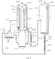
- the device includes a coke control reactor 1, a methanol conversion reactor 2, and a regenerator 3.
- the coke control reactor 1 can realize the on-line modification of a DMTO catalyst through a coke control reaction, including: a coke control reactor shell 1-1, a coke control reactor distributor 1-2, a baffle 1-3, a coke controlled catalyst delivery pipe 1-4, a coke controlled catalyst slide valve 1-5, and a coke control product gas delivery pipe 1-6; the coke control reactor 1 is divided into a reaction zone I, a transition zone, and a coke controlled catalyst settling zone from bottom to top, respectively; n baffles 1-3 are arranged in the reaction zone I, bottoms of the baffles 1-3 are connected to a bottom of the coke controlled reactor shell 1-1, and tops of the baffles 1-3 are located in the transition zone, where n is an integer and 1 ⁇ n ⁇ 9; the baffles 1-3 divide the reaction zone I into m reaction zone I subzones, where m is an integer and 2 ⁇ m ⁇ 10; a bottom of each of the reaction zone I subzones is
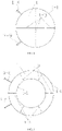
- a cross section of the reaction zone I of the coke control reactor 1 may be rectangular, a cross section of the reaction zone I subzone may be rectangular, and the 1 st to m th reaction zone I subzones may be arranged from left to right in sequence.
- a cross section of the reaction zone I of the coke control reactor 1 may be circular, and a cross section of a reaction zone I subzone may be fan-shaped; and the 1 st to m th reaction zone I subzones may be arranged concentrically in a clockwise or counterclockwise direction, and a baffle 1-3 shared by the 1 st reaction zone I subzone and the m th reaction zone I subzone of the coke control reactor 1 may not have catalyst circulation holes.
- a cross section of the reaction zone I of the coke control reactor 1 may be annular, and a cross section of a reaction zone I subzone may be sector-annular; and the 1 st to m th reaction zone I subzones may be arranged concentrically in a clockwise or counterclockwise direction, and a baffle 1-3 shared by the 1 st reaction zone I subzone and the m th reaction zone I subzone of the coke control reactor 1 may not have catalyst circulation holes.
- the coke control reactor 1 may be a bubbling fluidized bed reactor.
- the methanol conversion reactor 2 includes a methanol conversion reactor shell 2-1, a methanol conversion reactor distributor 2-2, a delivery pipe 2-3, a first gas-solid separation unit 2-4 of the methanol conversion reactor, a methanol conversion reactor gas collection chamber 2-5, a spent catalyst zone gas distributor 2-6, a methanol conversion reactor cooler 2-7, a second gas-solid separation unit 2-8 of the methanol conversion reactor, a product gas delivery pipe 2-9, a spent catalyst circulation pipe 2-10, a spent catalyst circulation slide valve 2-11, a spent catalyst inclined pipe 2-12, a methanol conversion reactor stripper 2-13, a spent catalyst slide valve 2-14, and a spent catalyst delivery pipe 2-15.
- a lower part of the methanol conversion reactor 2 is a reaction zone II, a middle part thereof is a spent catalyst zone, and an upper part thereof is a gas-solid separation zone.
- the methanol conversion reactor distributor 2-2 is located at a bottom of the reaction zone II of the methanol conversion reactor 2; the delivery pipe 2-3 is located in central zones of the middle and upper parts of the methanol conversion reactor 2; and a bottom end of the delivery pipe 2-3 is connected to a top end of the reaction zone II, and an upper part of the delivery pipe 2-3 is connected to an inlet of the first gas-solid separation unit 2-4 of the methanol conversion reactor.
- the first gas-solid separation unit 2-4 of the methanol conversion reactor is located in the gas-solid separation zone of the methanol conversion reactor; and a gas outlet of the first gas-solid separation unit 2-4 of the methanol conversion reactor is connected to the methanol conversion reactor gas collection chamber 2-5, and a catalyst outlet of the first gas-solid separation unit 2-4 of the methanol conversion reactor is formed in the spent catalyst zone.
- the spent catalyst zone gas distributor 2-6 is located at a bottom of the spent catalyst zone, and the methanol conversion reactor cooler 2-7 is located in the spent catalyst zone.
- the second gas-solid separation unit 2-8 of the methanol conversion reactor is located in the gas-solid separation zone of the methanol conversion reactor; an inlet of the second gas-solid separation unit 2-8 of the methanol conversion reactor is formed in the gas-solid separation zone of the methanol conversion reactor, a gas outlet of the second gas-solid separation unit 2-8 of the methanol conversion reactor is connected to the methanol conversion reactor gas collection chamber 2-5, and a catalyst outlet of the second gas-solid separation unit 2-8 of the methanol conversion reactor is formed in the spent catalyst zone;
- the methanol conversion reactor gas collection chamber 2-5 is located at a top of the methanol conversion reactor 2, and the product gas delivery pipe 2-9 is connected to a top of the methanol conversion reactor gas collection chamber 2-5; an inlet of the spent catalyst circulation pipe 2-10 is connected to the spent catalyst zone, and an outlet of the spent catalyst circulation pipe 2-10 is connected to the bottom of the reaction zone II of the methanol conversion reactor;
- the spent catalyst circulation slide valve 2-11 is arranged in the spent
- the first gas-solid separation unit 2-4 of the methanol conversion reactor may adopt one or more sets of gas-solid cyclone separators, and each set of gas-solid cyclone separators may include a first-stage gas-solid cyclone separator and a second-stage gas-solid cyclone separator.
- the second gas-solid separation unit 2-8 of the methanol conversion reactor may adopt one or more sets of gas-solid cyclone separators, and each set of gas-solid cyclone separators may include a first-stage gas-solid cyclone separator and a second-stage gas-solid cyclone separator.
- the methanol conversion reactor 2 may be a fluidized bed reactor.
- the regenerator 3 includes a regenerator shell 3-1, a regenerator distributor 3-2, a regenerator gas-solid separation unit 3-3, a regenerator gas collection chamber 3-4, a flue gas delivery pipe 3-5, a regenerator stripper 3-6, a regenerator cooler 3-7, a regenerated catalyst slide valve 3-8, and a regenerated catalyst delivery pipe 3-9.
- the regenerator distributor 3-2 is located at a bottom of the regenerator 3, and the regenerator gas-solid separation unit 3-3 is located at an upper part of the regenerator 3; an inlet of the regenerator gas-solid separation unit 3-3 is formed at an upper part of the regenerator 3, a gas outlet of the regenerator gas-solid separation unit 3-3 is connected to the regenerator gas collection chamber 3-4, and a catalyst outlet of the regenerator gas-solid separation unit 3-3 is formed at a lower part of the regenerator 3; the regenerator gas collection chamber 3-4 is located at a top of the regenerator 3, and the flue gas delivery pipe 3-5 is connected to a top of the regenerator gas collection chamber 3-4; the regenerator stripper 3-6 is located outside the regenerator shell 3-1, and an inlet pipe of the regenerator stripper 3-6 penetrates through the regenerator shell 3-1 and is opened above the regenerator distributor 3-2; the regenerator cooler 3-7 is located in the regenerator stripper 3-6; and an inlet of the regenerated catalyst slide valve 3-8 is connected to a bottom of the
- the regenerator gas-solid separation unit 3-3 may adopt one or more sets of gas-solid cyclone separators, and each set of gas-solid cyclone separators may include a first-stage gas-solid cyclone separator and a second-stage gas-solid cyclone separator.
- the regenerator 3 may be a fluidized bed reactor.
- the present application also provides an MTO method including the method for on-line modification of a DMTO catalyst through a coke control reaction, including the following steps:
- the product gas may be composed of 37 wt% to 60 wt% of ethylene, 33 wt% to 57 wt% of propylene, less than or equal to 5 wt% of C 4 -C 6 hydrocarbon compounds, and less than or equal to 4 wt% of other components; and the other components may be methane, ethane, propane, hydrogen, CO, CO 2 , and the like, and the total selectivity of ethylene and propylene in the product gas may be 93 wt% to 96 wt%.
- a mass of DME in the oxygen-containing compound is equivalently converted into a mass of methanol based on a mass of the element C, and a unit of the unit consumption of production is ton of methanol/ton of low-carbon olefins.
- the unit consumption of production may be 2.50 to 2.58 tons of methanol/ton of low-carbon olefins.
- the coke control raw material is a mixture of 6 wt% of butane, 81 wt% of butene, 2 wt% of methanol, and 11 wt% of water;
- the oxygen-containing compound is methanol;
- the spent catalyst zone fluidizing gas is nitrogen;
- the regeneration gas is air;
- an active component in the catalyst is an SAPO-34 molecular sieve;
- a coke content in the regenerated catalyst is about 1 wt%;
- a coke content in the coke controlled catalyst is about 4 wt%, where a total mass of polymethylbenzene and polymethylnaphthalene accounts for about 86 wt% of a total mass of coke, a mass of coke species with a molecular weight greater than184 accounts for about 11 wt% of a total mass of coke, and a quartile deviation of coke content distribution in the coke controlled catalyst is about 0.9 wt%; a coke content in the spent catalyst is about
- a WHSV of the oxygen-containing compound in the methanol conversion reactor is about 20 h -1 ;
- the product gas is composed of 60 wt% of ethylene, 33 wt% of propylene, 3 wt% of C 4 -C 6 hydrocarbon compounds, and 4 wt% of other components, where the other components include methane, ethane, propane, hydrogen, CO, CO 2 , and the like; and the unit consumption of production is 2.58 tons of methanol/ton of low-carbon olefins.
- the coke control raw material is a mixture of 22 wt% of methane, 24 wt% of ethane, 3 wt% of ethylene, 28 wt% of propane, 4 wt% of propylene, 7 wt% of hydrogen, and 12 wt% of water;
- the oxygen-containing compound is a mixture of 82 wt% of methanol and 18 wt% of DME;
- the spent catalyst zone fluidizing gas is water vapor;
- the regeneration gas is air;
- an active component in the catalyst is an SAPO-34 molecular sieve;
- a coke content in the regenerated catalyst is about 3 wt%;
- a coke content in the coke controlled catalyst is about 9 wt%, where a total mass of polymethylbenzene and polymethylnaphthalene accounts for about 70 wt% of a total mass of coke, a mass of coke species with a molecular weight greater than184 accounts for about 25 wt% of
- a WHSV of the oxygen-containing compound in the methanol conversion reactor is about 5 h -1 ;
- the product gas is composed of 37 wt% of ethylene, 57 wt% of propylene, 5 wt% of C 4 -C 6 hydrocarbon compounds, and 1 wt% of other components, where the other components include methane, ethane, propane, hydrogen, CO, CO 2 , and the like; and the unit consumption of production is 2.55 tons of methanol/ton of low-carbon olefins.
- the coke control raw material is a mixture of 1 wt% of propane, 1 wt% of propylene, 3 wt% of butane, 51 wt% of butene, 3 wt% of pentane, 22 wt% of pentene, 1 wt% of hexane, 7 wt% of hexene, 2 wt% of methanol, and 9 wt% of water;
- the oxygen-containing compound is DME;
- the spent catalyst zone fluidizing gas is nitrogen;
- the regeneration gas is a mixture of 50 wt% of air and 50 wt% of oxygen;
- an active component in the catalyst is an SAPO-34 molecular sieve;
- a coke content in the regenerated catalyst is about 1 wt%;
- a coke content in the coke controlled catalyst is about 6 wt%, where a total mass of polymethylbenzene and polymethylnaphthalene accounts for about 80 wt% of a
- a WHSV of the oxygen-containing compound in the methanol conversion reactor is about 9 h -1 ;
- the product gas is composed of 51 wt% of ethylene, 43 wt% of propylene, 2 wt% of C 4 -C 6 hydrocarbon compounds, and 4 wt% of other components, where the other components include methane, ethane, propane, hydrogen, CO, CO 2 , and the like; and the unit consumption of production is 2.55 tons of methanol/ton of low-carbon olefins.
- the coke control raw material is a mixture of 5 wt% of butane, 72 wt% of butene, 8 wt% of methanol, and 15 wt% of water;
- the oxygen-containing compound is methanol;
- the spent catalyst zone fluidizing gas is water vapor;
- the regeneration gas is a mixture of 50 wt% of air and 50 wt% of nitrogen;
- an active component in the catalyst is an SAPO-34 molecular sieve;
- a coke content in the regenerated catalyst is about 2 wt%;
- a coke content in the coke controlled catalyst is about 6 wt%, where a total mass of polymethylbenzene and polymethylnaphthalene accounts for about 82 wt% of a total mass of coke, a mass of coke species with a molecular weight greater than 184 accounts for about 13 wt% of a total mass of coke, and a quartile deviation of coke content distribution in the coke controlled catalyst
- a WHSV of the oxygen-containing compound in the methanol conversion reactor is about 13 h -1 ;
- the product gas is composed of 53 wt% of ethylene, 42 wt% of propylene, 4 wt% of C 4 -C 6 hydrocarbon compounds, and 1 wt% of other components, where the other components include methane, ethane, propane, hydrogen, CO, CO 2 , and the like; and the unit consumption of production is 2.52 tons of methanol/ton of low-carbon olefins.
- the coke control raw material is a mixture of 34 wt% of pentane, 46 wt% of pentene, 3 wt% of ethanol, and 17 wt% of water;
- the oxygen-containing compound is methanol;
- the spent catalyst zone fluidizing gas is a mixture of 5 wt% of nitrogen and 95 wt% of water vapor;
- the regeneration gas is a mixture of 50 wt% of air and 50 wt% of water vapor;
- an active component in the catalyst is an SAPO-34 molecular sieve;
- a coke content in the regenerated catalyst is about 2 wt%;
- a coke content in the coke controlled catalyst is about 7 wt%, where a total mass of polymethylbenzene and polymethylnaphthalene accounts for about 74 wt% of a total mass of coke, a mass of coke species with a molecular weight greater than 184 accounts for about 10 wt% of a total mass of co
- a WHSV of the oxygen-containing compound in the methanol conversion reactor is about 9 h -1 ;
- the product gas is composed of 41 wt% of ethylene, 55 wt% of propylene, 2 wt% of C 4 -C 6 hydrocarbon compounds, and 2 wt% of other components, where the other components include methane, ethane, propane, hydrogen, CO, CO 2 , and the like; and the unit consumption of production is 2.50 tons of methanol/ton of low-carbon olefins.
- the coke control raw material is a mixture of 26 wt% of hexane, 23 wt% of hexene, 2 wt% of methanol, 1 wt% of ethanol, and 48 wt% of water;
- the oxygen-containing compound is methanol;
- the spent catalyst zone fluidizing gas is a mixture of 73 wt% of nitrogen and 27 wt% of water vapor;
- the regeneration gas is a mixture of 85 wt% of air, 12 wt% of water vapor, and 3 wt% of nitrogen;
- an active component in the catalyst is an SAPO-34 molecular sieve;
- a coke content in the regenerated catalyst is about 3 wt%;
- a coke content in the coke controlled catalyst is about 8 wt%, where a total mass of polymethylbenzene and polymethylnaphthalene accounts for about 79 wt% of a total mass of coke, a mass of coke species with a
- a WHSV of the oxygen-containing compound in the methanol conversion reactor is about 7 h -1 ;
- the product gas is composed of 50 wt% of ethylene, 43 wt% of propylene, 4 wt% of C 4 -C 6 hydrocarbon compounds, and 3 wt% of other components, where the other components include methane, ethane, propane, hydrogen, CO, CO 2 , and the like; and the unit consumption of production is 2.58 tons of methanol/ton of low-carbon olefins.
- This example is a comparative example and is different from Example 5 in that, the coke control reaction is not used for on-line modification of the DMTO catalyst; and the raw material fed into the coke control reactor is nitrogen, which is an inert gas and does not change the properties of the regenerated catalyst in the coke control reactor, that is, a catalyst entering the reaction zone II of the methanol conversion reactor is the regenerated catalyst.
- the product gas is composed of 36 wt% of ethylene, 44 wt% of propylene, 13 wt% of C 4 -C 6 hydrocarbon compounds, and 7 wt% of other components, where the other components include methane, ethane, propane, hydrogen, CO, CO 2 , and the like; and the unit consumption of production is 2.99 tons of methanol/ton of low-carbon olefins.
- This comparative example shows that the on-line modification of a DMTO catalyst through a coke control reaction can greatly improve the performance of the catalyst and reduce the unit consumption of production.
Landscapes
- Chemical & Material Sciences (AREA)
- Organic Chemistry (AREA)
- Chemical Kinetics & Catalysis (AREA)
- Engineering & Computer Science (AREA)
- Combustion & Propulsion (AREA)
- Materials Engineering (AREA)
- Oil, Petroleum & Natural Gas (AREA)
- General Chemical & Material Sciences (AREA)
- Thermal Sciences (AREA)
- Physics & Mathematics (AREA)
- Organic Low-Molecular-Weight Compounds And Preparation Thereof (AREA)
- Devices And Processes Conducted In The Presence Of Fluids And Solid Particles (AREA)
- Low-Molecular Organic Synthesis Reactions Using Catalysts (AREA)
- Catalysts (AREA)
Abstract
Description
- The present application relates to a coke control reactor, and a device and method for preparing low-carbon olefins from an oxygen-containing compound, and belongs to the field of chemical catalysis.
- Methanol-to-olefin technology (MTO) mainly includes DMTO (methanol-to-olefin) technology of Dalian Institute of Chemical Physics, Chinese Academy of Sciences and MTO technology of UOP Company of the United States. In 2010, the Shenhua Baotou methanol-to-olefin plant using DMTO technology was completed and put into operation. This is the world's first industrial application of MTO technology. As of the end of 2019, 14 DMTO industrial plants have been put into production, with a total production capacity of about 8 million tons of low-carbon olefins per year.
- In recent years, DMTO technology has been further developed, and a new generation of DMTO catalyst with better performance have gradually begun industrial applications, creating higher benefits for DMTO plants. The new generation of DMTO catalyst has higher methanol processing capacity and low-carbon olefin selectivity. It is difficult for the existing DMTO industrial devices to take full advantage of the advantages of the new generation of DMTO catalyst. Therefore, it is necessary to develop a DMTO device and production method that can meet the needs of a new generation of DMTO catalyst with high methanol processing capacity and high selectivity of low-carbon olefins.
- According to an aspect of the present application, a coke control reactor is provided, which can achieve the on-line modification of a DMTO catalyst; and the modification in the present application refers to controlling the coke content, coke content distribution, and coke species in the DMTO catalyst to improve the activity of the DMTO catalyst and the selectivity for low-carbon olefins.
- A major characteristic of a DMTO catalyst is that the low-carbon olefin selectivity in a methanol conversion process increases with the increase of a coke content in the catalyst. The low-carbon olefins mentioned in the present application refer to ethylene and propylene.
- The applicants have found through research that main factors affecting the activity of a DMTO catalyst and the selectivity for low-carbon olefins include coke content, coke content distribution, and coke species in the catalyst. Under the same average coke content in catalysts, the narrower the coke content distribution, the higher the selectivity and activity of low-carbon olefins. Coke species in a catalyst may include polymethyl aromatic hydrocarbon compounds, polymethyl cycloalkanes, and the like, where polymethylbenzene and polymethylnaphthalene can promote the formation of ethylene. Therefore, the control of the coke content, coke content distribution, and coke species in a catalyst is the key to control the activity of the DMTO catalyst and improve the selectivity of low-carbon olefins.
- According to a first aspect of the present application, a coke control reactor is provided, where the coke control reactor includes a coke control reactor shell, a reaction zone I, and a coke controlled catalyst settling zone;
- the coke control reactor shell includes an upper coke control reactor shell and a lower coke control reactor shell; the upper coke control reactor shell encloses the coke controlled catalyst settling zone;
- the lower coke control reactor shell encloses the reaction zone I;
- the reaction zone I communicates with the coke controlled catalyst settling zone;
- a cross-sectional area at any position of the reaction zone I is less than a cross-sectional area at any position of the coke controlled catalyst settling zone;
- n baffles are arranged in a vertical direction in the reaction zone I, bottoms of the n baffles are connected to a bottom of the coke control reactor, tops of the n baffles are located in the coke controlled catalyst settling zone, and the n baffles divide the reaction zone I into m reaction zone I subzones, where m and n are both integers; and
- a catalyst circulation hole is formed in each of the baffles, such that a catalyst flows in the reaction zone I in a preset manner.
- Optionally, 1 ≤ n ≤ 9; and 2 ≤ m ≤ 10.
- Optionally, cross sections of the reaction zone I and the reaction zone I subzones may be all rectangular; a catalyst circulation hole may be formed in each of the n baffles; and catalyst circulation holes on adjacent baffles may be staggered up and down, such that a catalyst flows in the reaction zone I in a polyline manner.
- Optionally, a cross section of the reaction zone I may be circular; a cross section of each of the reaction zone I subzones may be fan-shaped; and at least one catalyst circulation hole may be formed in each of n-1 of the baffles, such that a catalyst flows in the reaction zone I in an annular manner.
- Optionally, a cross section of the reaction zone I may be annular; a cross section of each of the reaction zone I subzones may be fan-shaped; and at least one catalyst circulation hole may be formed in each of n-1 of the baffles, such that a catalyst flows in the reaction zone I in an annular manner.
- Optionally, when cross sections of the reaction zone I and the reaction zone I subzones in the present application are all rectangular, n baffles may be arranged in the reaction zone I, and the n baffles may divide the reaction zone I into n + 1 reaction zone I subzones, that is, m = n + 1.
- Optionally, when a cross section of the reaction zone I in the present application is circular, n baffles may be arranged in the reaction zone I, and the n baffles may divide the reaction zone I into n reaction zone I subzones, that is, m = n; and a diameter of the coke controlled catalyst settling zone may be larger than a diameter of the reaction zone I.
- Optionally, when a cross section of the reaction zone I in the present application is annular, n baffles may be arranged in the reaction zone I, and the n baffles may divide the reaction zone I into n reaction zone I subzones, that is, m = n; a cylinder may be arranged in a center of the reaction zone I, and the baffles may be connected to a side wall of the cylinder, such that the cross section of each of the reaction zone I subzones is sector-annular; and a diameter of the coke controlled catalyst settling zone may be larger than a diameter of the reaction zone I.
- Optionally, a cross-sectional area of the coke controlled catalyst settling zone may be 1.5 to 3 times a cross-sectional area of the reaction zone I.
- Specifically, one or more catalyst circulation holes can be formed in each of the baffles, which is not strictly limited in the present application. When a plurality of catalyst circulation holes are formed, relative positions of the catalyst circulation holes are not strictly limited in the present application. For example, the plurality of catalyst circulation holes may be arranged in parallel, or may be arranged randomly.
- Optionally, the coke control reactor may further include a transition zone;
- the transition zone may be located between the reaction zone I and the coke controlled catalyst settling zone;
- a cross-sectional area at any position of the transition zone may be between the cross-sectional area at any position of the reaction zone I and the cross-sectional area at any position of the coke controlled catalyst settling zone; and
- the transition zone, the reaction zone I, and the coke controlled catalyst settling zone may communicate with each other coaxially.
- Specifically, the transition zone in the present application may be configured to connect the reaction zone I and the coke controlled catalyst settling zone.
- Optionally, upper ends of the baffles in the present application may be located in the transition zone, and lower ends of the baffles may be connected to a bottom of the reaction zone I.
- Optionally, the coke control reactor may be a bubbling fluidized bed reactor.
- Optionally, the reaction zone I may include a catalyst inlet, a coke controlled catalyst outlet, and a coke control raw material inlet;
- the m reaction zone I subzones may include a 1st reaction zone I subzone, and a 2nd reaction zone I subzone to an mth reaction zone I subzone; the catalyst inlet may be formed in the 1st reaction zone I subzone; the coke controlled catalyst outlet may be formed in the mth reaction zone I subzone;
- the coke control raw material inlet may be formed at a bottom of each of the reaction zone I subzones;
- the coke controlled catalyst settling zone may include a coke control gas outlet; and the coke control gas outlet may be formed at a top of the coke controlled catalyst settling zone.
- Preferably, a coke control reactor distributor may be provided at the coke control raw material inlet for feeding a coke control raw material.
- Optionally, a coke control product gas delivery pipe may be provided at the coke control gas outlet.
- Optionally, a coke control reactor distributor may be provided at a bottom of each of the reaction zone I subzones. In this way, the coke control raw material can enter the reaction zone I uniformly as a whole, such that the phenomenon of non-uniform distribution of the coke control raw material among the subzones can be avoided, and the narrow coke content distribution in a catalyst can be well achieved.
- Optionally, a coke controlled catalyst delivery pipe may be provided at the coke controlled catalyst outlet for delivering a coke controlled catalyst to the reaction zone II.
- In the present application, a shape of the coke controlled catalyst delivery pipe is not strictly limited, as long as it is ensured that the coke controlled catalyst delivery pipe can deliver a coke controlled catalyst to the reaction zone. For example, the coke controlled catalyst delivery pipe can be a long pipe with a bent structure, and can also be in other suitable shapes.
- Optionally, a coke controlled catalyst slide valve may be further provided on the coke controlled catalyst delivery pipe for controlling the circulation of a catalyst.
- In the present application, baffles with circulation holes are arranged in the reaction zone I to divide the coke control zone into a plurality of reaction zone I subzones, such that a catalyst can flow regularly in the reaction zone I, which controls a residence time of a catalyst entering the reaction zone I and a coke control mode to enable a narrow coke content distribution in the catalyst and control the coke species and coke content in the catalyst. The low uniformity of coke content on catalyst granules is avoided, that is, some catalyst granules have a low coke content, and some catalyst granules have a high coke content, resulting in a wide coke content distribution in the catalyst.
- In the present application, the catalyst entering the coke control zone may be a fresh catalyst or a regenerated catalyst. Preferably, the catalyst may be a regenerated catalyst, such that both the regeneration and the coke control can be achieved on-line.
- According to a second aspect of the present application, a method for on-line modification of a DMTO catalyst is provided, which is implemented using the above-mentioned coke control reactor.
- Optionally, the method may at least include feeding a catalyst and a coke control raw material into the reaction zone I to allow a reaction to generate a product with a coke controlled catalyst,
where the catalyst flows in a preset manner through the catalyst circulation holes on the baffles. - Optionally, the coke control raw material may include C1-C6 hydrocarbon compounds.
- Preferably, the hydrocarbon compounds may be at least one from the group consisting of C1-C6 alkanes and C1-C6 olefins.
- Optionally, a reaction temperature of the coke control reaction may be 300°C to 700°C.
- Optionally, the coke control reactor in the present application may be a bubbling fluidized bed reactor.
- Optionally, the coke control raw material may further include at least one from the group consisting of hydrogen, alcohol compound, and water; and
- a proportion of a total mass of the alcohol compound and the water in a mass of the coke control raw material may be greater than or equal to 10% and less than or equal to 50%; and
- preferably, the alcohol compound may be at least one from the group consisting of methanol and ethanol.
- Optionally, the coke control raw material may include 0 wt% to 20 wt% of hydrogen, 0 wt% to 50 wt% of methane, 0 wt% to 50 wt% of ethane, 0 wt% to 20 wt% of ethylene, 0 wt% to 50 wt% of propane, 0 wt% to 20 wt% of propylene, 0 wt% to 90 wt% of butane, 0 wt% to 90 wt% of butene, 0 wt% to 90 wt% of pentane, 0 wt% to 90 wt% of pentene, 0 wt% to 90 wt% of hexane, 0 wt% to 90 wt% of hexene, 0 wt% to 50 wt% of methanol, 0 wt% to 50 wt% of ethanol, and 0 wt% to 50 wt% of water; and
a content of the hydrocarbon compounds may be greater than 0%. - Optionally, the catalyst may include an SAPO-34 molecular sieve; a coke content in the catalyst may be less than or equal to 3 wt%;
- a coke content in the coke controlled catalyst may be 4 wt% to 9 wt%;
- a quartile deviation of a coke content distribution in the coke controlled catalyst may be less than 1 wt%;
- preferably, coke species in the coke controlled catalyst may include polymethylbenzene and polymethylnaphthalene;
- a total mass of the polymethylbenzene and the polymethylnaphthalene may account for greater than or equal to 70 wt% of a total mass of coke;
- a mass of coke species with a molecular weight greater than 184 may account for less than or equal to 25 wt% of the total mass of coke; and
- the total mass of coke may refer to a total mass of coke species.
- Specifically, in the present application, the coke content in the coke controlled catalyst is controlled at 4 wt% to 9 wt% through the arrangement of the reaction zone I and the selection of the coke control process. Since the catalyst is powdery, the coke content in the catalyst refers to an average coke content in catalyst granules, but coke contents in different catalyst granules may actually be different. In the present application, the quartile deviation of the coke content distribution in the coke controlled catalyst granules can be controlled to be less than 1 wt%, such that the overall coke content distribution of the catalyst is narrow, thereby improving the activity of the catalyst and the selectivity for low-carbon olefins.
- In the present application, types and contents of coke species are also very important, which is also one of the objectives of control in the present application. In the present application, a total mass of the polymethylbenzene and the polymethylnaphthalene is controlled to be greater than or equal to 70 wt% of the total mass of coke through the arrangement of coke control and the selection of coke control process parameters to improve the activity of the catalyst and the selectivity for low-carbon olefins.
- Optionally, process operating conditions of the reaction zone I of the coke control reactor may be as follows: apparent gas linear velocity: 0.1 m/s to 0.5 m/s; reaction temperature: 300°C to 700°C; reaction pressure: 100 kPa to 500 kPa; and bed density: 400 kg/m3 to 800 kg/m3.
- Optionally, the method may include: feeding a coke control raw material and a catalyst into the reaction zone I to allow a reaction to generate a coke controlled catalyst and a coke control product gas; allowing the coke controlled catalyst to pass through the m reaction zone I subzones in sequence through the catalyst circulation holes on the baffles and then flow out through the coke controlled catalyst outlet; and allowing the coke control product gas to flow out through the coke control gas outlet.
- According to a third aspect of the present application, a device for preparing low-carbon olefins from an oxygen-containing compound is provided, including a methanol conversion reactor and the coke control reactor described above.
- Optionally, the methanol conversion reactor may include a methanol conversion reactor shell and a delivery pipe;
- the methanol conversion reactor shell may include a lower methanol conversion reactor shell and an upper methanol conversion reactor shell;
- the lower methanol conversion reactor shell may enclose a reaction zone II;
- the delivery pipe may be located above the reaction zone II; the delivery pipe may have one end closed and the other end communicating with the reaction zone II;
- the upper methanol conversion reactor shell may be arranged on a periphery of the delivery pipe;
- the upper methanol conversion reactor shell and a pipe wall of the delivery pipe may enclose a cavity;
- the cavity may be divided into a spent catalyst zone and a gas-solid separation zone from bottom to top, respectively; and
- the spent catalyst zone may be provided with a spent catalyst zone gas distributor.
- Optionally, a bottom of the reaction zone II may be provided with a methanol conversion reactor distributor,
- Optionally, the spent catalyst zone may be further provided with a methanol conversion reactor cooler, and the methanol conversion reactor cooler may be located above the spent catalyst zone gas distributor and below the gas-solid separation zone.
- Optionally, the coke control product gas delivery pipe may communicate with the gas-solid separation zone, and may be configured to deliver a coke control product gas to the gas-solid separation zone.
- Optionally, the gas-solid separation zone may be provided with a first gas-solid separation unit of the methanol conversion reactor;
- an upper part of the delivery pipe may be connected to an inlet of the first gas-solid separation unit of the methanol conversion reactor;
- a spent catalyst outlet of the first gas-solid separation unit of the methanol conversion reactor may be formed in the spent catalyst zone;
- a gas outlet of the first gas-solid separation unit of the methanol conversion reactor may communicate with a methanol conversion reactor gas collection chamber; and
- the methanol conversion reactor gas collection chamber may communicate with a product gas delivery pipe.
- Optionally, the gas-solid separation zone may be further provided with a second gas-solid separation unit of the methanol conversion reactor;
- a gas inlet of the second gas-solid separation unit of the methanol conversion reactor may be formed in the gas-solid separation zone;
- a spent catalyst outlet of the second gas-solid separation unit of the methanol conversion reactor may be formed in the spent catalyst zone; and
- a gas outlet of the second gas-solid separation unit of the methanol conversion reactor may communicate with the methanol conversion reactor gas collection chamber.
- Optionally, the first gas-solid separation unit of the methanol conversion reactor may adopt one or more sets of gas-solid cyclone separators, and each set of gas-solid cyclone separators may include a first-stage gas-solid cyclone separator and a second-stage gas-solid cyclone separator.
- Optionally, the second gas-solid separation unit of the methanol conversion reactor may adopt one or more sets of gas-solid cyclone separators, and each set of gas-solid cyclone separators may include a first-stage gas-solid cyclone separator and a second-stage gas-solid cyclone separator.
- Optionally, the spent catalyst zone gas distributor may be located below the first gas-solid separation unit of the methanol conversion reactor and the second gas-solid separation unit of the methanol conversion reactor.
- Optionally, a spent catalyst circulation pipe and a spent catalyst inclined pipe may be further arranged outside the spent catalyst zone;
- the spent catalyst circulation pipe may be configured to connect the spent catalyst zone and the reaction zone II; and
- the spent catalyst inclined pipe may be configured to output a spent catalyst.
- Optionally, the spent catalyst circulation pipe may be further provided with a spent catalyst circulation slide valve configured to control the circulation of a catalyst.
- Optionally, one end of the spent catalyst circulation pipe may be connected to the reaction zone II, and may be located above the methanol conversion reactor distributor; and the other end may be connected to the spent catalyst zone.
- Optionally, the reaction zone II may communicate with the reaction zone I through a coke controlled catalyst delivery pipe.
- Optionally, the device may further include a regenerator;
- the regenerator may be connected to the spent catalyst inclined pipe, such that a spent catalyst is able to be delivered to the regenerator;
- the regenerator may be connected to a regenerated catalyst delivery pipe, such that a regenerated catalyst is able to be delivered to the coke control reactor; and
- an inner bottom of the regenerator may be provided with a regenerator distributor.
- Optionally, a bottom of the regenerator may be further provided with a regenerator stripper; an upper section of the regenerator stripper may be arranged inside the regenerator, and an inlet of the upper section of the regenerator stripper may be formed above the regenerator distributor; and
a lower section of the regenerator stripper may be arranged outside the regenerator, and an outlet of the lower section of the regenerator stripper may be connected to the regenerated catalyst delivery pipe. - Optionally, the regenerator may include a regenerator shell and a regenerator stripper; a lower section of the regenerator stripper may be arranged outside the regenerator shell, and an outlet of the lower section of the regenerator stripper may be connected to the regenerated catalyst delivery pipe. An upper section of the regenerator stripper may be arranged inside the regenerator shell, and an inlet of the upper section of the regenerator stripper may be formed above the regenerator distributor.
- Optionally, the regenerator may be connected to the spent catalyst inclined pipe through a spent catalyst delivery pipe and a methanol conversion reactor stripper; and
the regenerator may be connected to the regenerated catalyst delivery pipe through the regenerator stripper. - Optionally, a spent catalyst slide valve may be further arranged between the methanol conversion reactor stripper and the spent catalyst delivery pipe.
- Optionally, the regenerator may be further provided with a regenerator gas-solid separation unit and a regenerator gas collection chamber;
- a regenerated catalyst outlet of the regenerator gas-solid separation unit may be formed above the regenerator distributor;
- a gas outlet of the regenerator gas-solid separation unit may be connected to the regenerator gas collection chamber; and
- the regenerator gas collection chamber may be connected to a flue gas delivery pipe located outside the regenerator.
- Optionally, the regenerator stripper may be further provided with a regenerator cooler.
- Optionally, the regenerator gas-solid separation unit may adopt one or more sets of gas-solid cyclone separators, and each set of gas-solid cyclone separators may include a first-stage gas-solid cyclone separator and a second-stage gas-solid cyclone separator.
- Optionally, a regenerated catalyst slide valve may be further arranged between the regenerator stripper and the regenerated catalyst delivery pipe.
- According to a fourth aspect of the present application, a method for preparing low-carbon olefins from an oxygen-containing compound is provided, including the method for on-line modification of a DMTO catalyst described above.
- Optionally, the method may further include: feeding a coke control product gas into a gas-solid separation zone of a methanol conversion reactor; and
feeding a coke controlled catalyst into a reaction zone II of the methanol conversion reactor. - Optionally, in the reaction zone II, a raw material with an oxygen-containing compound may contact and react with the coke controlled catalyst to generate a stream A with low-carbon olefins and a spent catalyst.
- Optionally, the stream A may be separated into a gas-phase stream B and a solid-phase stream C after being subjected to gas-solid separation in the gas-solid separation zone of the methanol conversion reactor;
- the gas-phase stream B may enter a methanol conversion reactor gas collection chamber;
- the solid-phase stream C may enter a spent catalyst zone; and
- the gas-phase stream B may include the low-carbon olefins, and the solid-phase stream C may include the spent catalyst.
- Optionally, a spent catalyst zone fluidizing gas may be fed into the spent catalyst zone;
- the spent catalyst zone fluidizing gas and a coke control product gas may be mixed and carry a part of the spent catalyst to produce a stream D;
- the stream D may be separated into a gas-phase stream E and a solid-phase stream F after being subjected to gas-solid separation;
- the gas-phase stream E may enter the methanol conversion reactor gas collection chamber;
- the solid-phase stream F may enter the spent catalyst zone;
- the gas-phase stream E may be a mixed gas of the spent catalyst zone fluidizing gas and the coke control product gas; and
- the solid-phase stream F may be the spent catalyst.
- Optionally, the gas-phase stream B and the gas-phase stream E may be mixed in the methanol conversion reactor gas collection chamber to produce a product gas, and the product gas may enter a downstream working section through a product gas delivery pipe.
- Optionally, a part of the spent catalyst in the spent catalyst zone may be returned to a bottom of the reaction zone II through a spent catalyst circulation pipe; and
the remaining part of the spent catalyst may be discharged through a spent catalyst inclined pipe. - Optionally, the spent catalyst discharged through the spent catalyst inclined pipe may be fed into a regenerator; and
a regeneration gas may be fed into the regenerator to contact and react with the spent catalyst to obtain a stream G with a flue gas and a regenerated catalyst. - Optionally, the stream G may be subjected to gas-solid separation;
- a separated flue gas may enter a regenerator gas collection chamber, and then enter a downstream flue gas treatment system through a flue gas delivery pipe; and
- a separated regenerated catalyst may be stripped and cooled, and then enter a coke control reactor.
- Optionally, the oxygen-containing compound may include methanol and/or dimethyl ether (DME).
- Optionally, a coke content in the spent catalyst may be 9 wt% to 13 wt%.
- Optionally, the spent catalyst zone fluidizing gas may include nitrogen and/or water vapor.
- Optionally, the regeneration gas may include 0 wt% to 100 wt% of air, 0 wt% to 50 wt% of oxygen, 0 wt% to 50 wt% of nitrogen, and 0 wt% to 50 wt% of water vapor.
- Optionally, process operating conditions of the reaction zone II of the methanol conversion reactor may be as follows: apparent gas linear velocity: 0.5 m/s to 7.0 m/s; reaction temperature: 350°C to 550°C; reaction pressure: 100 kPa to 500 kPa; and bed density: 100 kg/m3 to 500 kg/m3.
- Optionally, process operating conditions of the spent catalyst zone of the methanol conversion reactor may be as follows: apparent gas linear velocity: 0.1 m/s to 1.0 m/s; reaction temperature: 350°C to 550°C; reaction pressure: 100 kPa to 500 kPa; and bed density: 200 kg/m3 to 800 kg/m3.
- Optionally, process operating conditions of the regenerator may be as follows: apparent gas linear velocity: 0.5 m/s to 2.0 m/s; regeneration temperature: 600°C to 750°C; regeneration pressure: 100 kPa to 500 kPa; and bed density: 150 kg/m3 to 700 kg/m3.
- The C1-C6 hydrocarbon compounds in the present application refer to hydrocarbon compounds with 1 to 6 carbon atoms.
- Possible beneficial effects of the present application:
- (1) The coke control reactor in the present application is a bubbling fluidized bed reactor with m reaction zone subzones, where a height of a baffle between adjacent reaction zone subzones is higher than a height of a catalyst dense bed, and a catalyst can flow from an upstream subzone to a downstream subzone only through catalyst circulation holes in the baffles, such that, 1. a catalyst charge in the coke control reactor can be automatically adjusted (that is, an average residence time of a catalyst in the coke control reactor can be controlled by changing process operating conditions to control a coke content in the catalyst); and 2. a residence time distribution of a catalyst is controlled with the structure of m reaction zone subzones (the residence time distribution is similar to m serially-connected completely-mixed tank reactors), and thus a catalyst with a narrow coke content distribution can be obtained.
- (2) The present application can control the conversion and generation of coke species in a catalyst. On the one hand, inactive large-molecule coke species remaining in a regenerated catalyst are converted into small-molecule coke species; and on the other hand, a coke control raw material can also enter the catalyst to generate highly-active small-molecule coke species, and the small-molecule coke species are mainly polymethylbenzene and polymethylnaphthalene, which can improve the selectivity for ethylene.
- (3) With the method for on-line modification of a DMTO catalyst through a coke control reaction in the present application, a coke controlled catalyst with high coke content, narrow coke content distribution, and polymethylbenzene and polymethylnaphthalene as main coke species components can be obtained, that is, the regenerated catalyst with low selectivity for low-carbon olefins is converted into a coke controlled catalyst with high selectivity for low-carbon olefins.
- (4) The regenerated catalyst in the present application can be directly used in the process of preparing low-carbon olefins from an oxygen-containing compound without a coke control treatment, and in this case, the selectivity for low-carbon olefins in an obtained product gas is 80 wt% to 83 wt%. When the regenerated catalyst in the present application is subjected to a coke control treatment and then used in the process of preparing low-carbon olefins from an oxygen-containing compound, the selectivity for low-carbon olefins in an obtained product gas is 93 wt% to 96 wt%.
- (5) The methanol conversion reactor in the present application is a composite fluidized bed reactor including a fast fluidized bed zone and a bubbling fluidized bed zone. The fast fluidized bed zone is a reaction zone, which can obtain a high methanol flux, increase a methanol treatment capacity per unit volume of the device, and make a methanol weight hourly space velocity (WHSV) reach 5 h-1 to 20 h-1. The bubbling fluidized bed zone is a spent catalyst zone, which is configured to reduce a temperature of a spent catalyst, deliver a low-temperature spent catalyst to the reaction zone, increase a bed density of the reaction zone, and control a bed temperature of the reaction zone. When the apparent gas linear velocity is 0.5 m/s to 7.0 m/s, a corresponding bed density is 500 kg/m3 to 100 kg/m3.
- (6) The methanol conversion reactor in the present application adopts a structure in which the first gas-solid separation unit of the methanol conversion reactor is directly connected to the delivery pipe, which realizes the rapid separation of a low-carbon olefin-containing gas and a spent catalyst in the stream A, and avoids that low-carbon olefins further react under the action of the spent catalyst to generate hydrocarbon by-products with a large molecular weight.
-
-
FIG. 1 is a schematic diagram of a DMTO device for preparing low-carbon olefins from an oxygen-containing compound according to an embodiment of the present application.
Reference numerals inFIG. 1 :
1 represents a coke control reactor; 1-1 represents a coke control reactor shell; 1-2 represents a coke control reactor distributor; 1-3 represents a baffle; 1-4 represents a coke controlled catalyst delivery pipe; 1-5 represents a coke controlled catalyst slide valve; 1-6 represents a coke control product gas delivery pipe; 2 represents a methanol conversion reactor; 2-1 represents a methanol conversion reactor shell; 2-2 represents a methanol conversion reactor distributor; 2-3 represents a delivery pipe; 2-4 represents a first gas-solid separation unit of the methanol conversion reactor; 2-5 represents a methanol conversion reactor gas collection chamber; 2-6 represents a spent catalyst zone gas distributor; 2-7 represents a methanol conversion reactor cooler; 2-8 represents a second gas-solid separation unit of the methanol conversion reactor; 2-9 represents a product gas delivery pipe; 2-10 represents a spent catalyst circulation pipe; 2-11 represents a spent catalyst circulation slide valve; 2-12 represents a spent catalyst inclined pipe; 2-13 represents a methanol conversion reactor stripper; 2-14 represents a spent catalyst slide valve; 2-15 represents a spent catalyst delivery pipe; 3 represents a regenerator; 3-1 represents a regenerator shell; 3-2 represents a regenerator distributor; 3-3 represents a regenerator gas-solid separation unit; 3-4 represents a regenerator gas collection chamber; 3-5 represents a flue gas delivery pipe; 3-6 represents a regenerator stripper; 3-7 represents a regenerator cooler; 3-8 represents a regenerated catalyst slide valve; and 3-9 represents a regenerated catalyst delivery pipe. -
FIG. 2 is a schematic diagram of cross sections of a structure of the reaction zone of the coke control reactor of an embodiment of the present application, where a cross section of the reaction zone I of the coke control reactor of the embodiment is circular, and a cross section of a reaction zone subzone is fan-shaped; and the 1st to 4th reaction zone subzones are arranged concentrically in a counterclockwise direction, and a baffle shared by the 1st reaction zone subzone and the 4th reaction zone subzone of the coke control reactor does not have catalyst circulation holes.
Reference numerals inFIG. 2 :
1 represents a coke control reactor; 1-1 represents a coke control reactor shell; 1-3 represents a baffle; 1-4 represents a coke controlled catalyst delivery pipe; and 3-9 represents a regenerated catalyst delivery pipe. -
FIG. 3 is a schematic diagram of cross sections of a structure of the reaction zone of the coke control reactor of an embodiment of the present application, where a cross section of the reaction zone I of the coke control reactor of the embodiment is annular, and a cross section of a reaction zone subzone is sector-annular; and the 1st to 6th reaction zone subzones are arranged concentrically in a clockwise direction, and a baffle shared by the 1st reaction zone subzone and the 6th reaction zone subzone of the coke control reactor does not have catalyst circulation holes.
Reference numerals inFIG. 3 :
1 represents a coke control reactor; 1-1 represents a coke control reactor shell; 1-3 represents a baffle; 1-4 represents a coke controlled catalyst delivery pipe; and 3-9 represents a regenerated catalyst delivery pipe. - The present application will be described in detail below with reference to examples, but the present application is not limited to these examples.
- Unless otherwise specified, the raw materials and catalysts in the examples of the present application are all purchased from commercial sources.
- The DMTO catalyst used in the examples of the present application is from Zhongke Catalysis (Dalian) Co., Ltd.
- In order to improve the performance of a DMTO catalyst, the present application provides a method for on-line modification of a DMTO catalyst through a coke control reaction, including the following steps:
- (a) a regenerated catalyst is delivered to a
coke control reactor 1; - (b) a coke control raw material is delivered to a
coke control reactor 1; - (c) the coke control raw material contacts and reacts with the regenerated catalyst in the
coke control reactor 1, such that the coke control raw material is coked on the regenerated catalyst, where a coked catalyst is called a coke controlled catalyst; a coke content in the coke controlled catalyst is 4 wt% to 9 wt%; coke species include polymethylbenzene and polymethylnaphthalene, and a total mass of the polymethylbenzene and the polymethylnaphthalene accounts for greater than or equal to 70 wt% of a total mass of coke; and a mass of coke species with a molecular weight greater than 184 accounts for less than or equal to 25 wt% of the total mass of coke; and - (d) the coke controlled catalyst is delivered to a
methanol conversion reactor 2. - A reaction temperature of the coke control reaction may be 300°C to 700°C.
- The present application also provides a method for preparing low-carbon olefins from an oxygen-containing compound that includes the method for on-line modification of a DMTO catalyst through a coke control reaction described above, and a device used thereby. The device includes a
coke control reactor 1, amethanol conversion reactor 2, and aregenerator 3. - The coke control reactor 1 can realize the on-line modification of a DMTO catalyst through a coke control reaction, including: a coke control reactor shell 1-1, a coke control reactor distributor 1-2, a baffle 1-3, a coke controlled catalyst delivery pipe 1-4, a coke controlled catalyst slide valve 1-5, and a coke control product gas delivery pipe 1-6; the coke control reactor 1 is divided into a reaction zone I, a transition zone, and a coke controlled catalyst settling zone from bottom to top, respectively; n baffles 1-3 are arranged in the reaction zone I, bottoms of the baffles 1-3 are connected to a bottom of the coke controlled reactor shell 1-1, and tops of the baffles 1-3 are located in the transition zone, where n is an integer and 1 ≤ n ≤ 9; the baffles 1-3 divide the reaction zone I into m reaction zone I subzones, where m is an integer and 2 ≤ m ≤ 10; a bottom of each of the reaction zone I subzones is independently provided with a coke control reactor distributor 1-2, and m coke control reactor distributors 1-2 are arranged in the reaction zone I; an outlet of the regenerated catalyst delivery pipe 3-9 is connected to the 1st reaction zone I subzone of the coke controlled reactor 1, and an inlet of the coke controlled catalyst delivery pipe 1-4 is connected to the mth reaction zone I subzone of the coke control reactor 1; a catalyst circulation hole is formed in each of the baffles 1-3, and catalyst circulation holes on adjacent upper and lower baffles 1-3 are staggered; a coke controlled catalyst slide valve 1-5 is arranged in the coke controlled catalyst delivery pipe 1-4, and an outlet of the coke controlled catalyst delivery pipe 1-4 is connected to a lower part of the methanol conversion reactor 2; and an inlet of the coke control product gas delivery pipe 1-6 is connected to a top of the coke control reactor 1, and an outlet of the coke control product gas delivery pipe 1-6 is connected to an upper part of the methanol conversion reactor 2.
- In a preferred embodiment, a cross section of the reaction zone I of the
coke control reactor 1 may be rectangular, a cross section of the reaction zone I subzone may be rectangular, and the 1st to mth reaction zone I subzones may be arranged from left to right in sequence. - In a preferred embodiment, a cross section of the reaction zone I of the
coke control reactor 1 may be circular, and a cross section of a reaction zone I subzone may be fan-shaped; and the 1st to mth reaction zone I subzones may be arranged concentrically in a clockwise or counterclockwise direction, and a baffle 1-3 shared by the 1st reaction zone I subzone and the mth reaction zone I subzone of thecoke control reactor 1 may not have catalyst circulation holes. - In a preferred embodiment, a cross section of the reaction zone I of the
coke control reactor 1 may be annular, and a cross section of a reaction zone I subzone may be sector-annular; and the 1st to mth reaction zone I subzones may be arranged concentrically in a clockwise or counterclockwise direction, and a baffle 1-3 shared by the 1st reaction zone I subzone and the mth reaction zone I subzone of thecoke control reactor 1 may not have catalyst circulation holes. - The
coke control reactor 1 may be a bubbling fluidized bed reactor. - The
methanol conversion reactor 2 includes a methanol conversion reactor shell 2-1, a methanol conversion reactor distributor 2-2, a delivery pipe 2-3, a first gas-solid separation unit 2-4 of the methanol conversion reactor, a methanol conversion reactor gas collection chamber 2-5, a spent catalyst zone gas distributor 2-6, a methanol conversion reactor cooler 2-7, a second gas-solid separation unit 2-8 of the methanol conversion reactor, a product gas delivery pipe 2-9, a spent catalyst circulation pipe 2-10, a spent catalyst circulation slide valve 2-11, a spent catalyst inclined pipe 2-12, a methanol conversion reactor stripper 2-13, a spent catalyst slide valve 2-14, and a spent catalyst delivery pipe 2-15. - A lower part of the
methanol conversion reactor 2 is a reaction zone II, a middle part thereof is a spent catalyst zone, and an upper part thereof is a gas-solid separation zone. - The methanol conversion reactor distributor 2-2 is located at a bottom of the reaction zone II of the
methanol conversion reactor 2; the delivery pipe 2-3 is located in central zones of the middle and upper parts of themethanol conversion reactor 2; and a bottom end of the delivery pipe 2-3 is connected to a top end of the reaction zone II, and an upper part of the delivery pipe 2-3 is connected to an inlet of the first gas-solid separation unit 2-4 of the methanol conversion reactor. - The first gas-solid separation unit 2-4 of the methanol conversion reactor is located in the gas-solid separation zone of the methanol conversion reactor; and a gas outlet of the first gas-solid separation unit 2-4 of the methanol conversion reactor is connected to the methanol conversion reactor gas collection chamber 2-5, and a catalyst outlet of the first gas-solid separation unit 2-4 of the methanol conversion reactor is formed in the spent catalyst zone.
- The spent catalyst zone gas distributor 2-6 is located at a bottom of the spent catalyst zone, and the methanol conversion reactor cooler 2-7 is located in the spent catalyst zone.
- The second gas-solid separation unit 2-8 of the methanol conversion reactor is located in the gas-solid separation zone of the methanol conversion reactor; an inlet of the second gas-solid separation unit 2-8 of the methanol conversion reactor is formed in the gas-solid separation zone of the methanol conversion reactor, a gas outlet of the second gas-solid separation unit 2-8 of the methanol conversion reactor is connected to the methanol conversion reactor gas collection chamber 2-5, and a catalyst outlet of the second gas-solid separation unit 2-8 of the methanol conversion reactor is formed in the spent catalyst zone; the methanol conversion reactor gas collection chamber 2-5 is located at a top of the methanol conversion reactor 2, and the product gas delivery pipe 2-9 is connected to a top of the methanol conversion reactor gas collection chamber 2-5; an inlet of the spent catalyst circulation pipe 2-10 is connected to the spent catalyst zone, and an outlet of the spent catalyst circulation pipe 2-10 is connected to the bottom of the reaction zone II of the methanol conversion reactor; the spent catalyst circulation slide valve 2-11 is arranged in the spent catalyst circulation pipe 2-10; an outlet of the coke controlled catalyst delivery pipe 1-4 is connected to the bottom of the reaction zone II of the methanol conversion reactor 2, an inlet of the spent catalyst inclined pipe 2-12 is connected to the spent catalyst zone, and an outlet of the spent catalyst inclined pipe 2-12 is connected to an upper part of the methanol conversion reactor stripper 2-13; the methanol conversion reactor stripper 2-13 is arranged outside the methanol conversion reactor shell 2-1; and an inlet of the spent catalyst slide valve 2-14 is connected to a bottom of the methanol conversion reactor stripper 2-13 through a pipeline, an outlet of the spent catalyst slide valve 2-14 is connected to an inlet of the spent catalyst delivery pipe 2-15 through a pipeline, and an outlet of the spent catalyst delivery pipe 2-15 is connected to a middle part of the regenerator 3.
- In a preferred embodiment, the first gas-solid separation unit 2-4 of the methanol conversion reactor may adopt one or more sets of gas-solid cyclone separators, and each set of gas-solid cyclone separators may include a first-stage gas-solid cyclone separator and a second-stage gas-solid cyclone separator.
- In a preferred embodiment, the second gas-solid separation unit 2-8 of the methanol conversion reactor may adopt one or more sets of gas-solid cyclone separators, and each set of gas-solid cyclone separators may include a first-stage gas-solid cyclone separator and a second-stage gas-solid cyclone separator.
- The
methanol conversion reactor 2 may be a fluidized bed reactor. - The
regenerator 3 includes a regenerator shell 3-1, a regenerator distributor 3-2, a regenerator gas-solid separation unit 3-3, a regenerator gas collection chamber 3-4, a flue gas delivery pipe 3-5, a regenerator stripper 3-6, a regenerator cooler 3-7, a regenerated catalyst slide valve 3-8, and a regenerated catalyst delivery pipe 3-9. The regenerator distributor 3-2 is located at a bottom of the regenerator 3, and the regenerator gas-solid separation unit 3-3 is located at an upper part of the regenerator 3; an inlet of the regenerator gas-solid separation unit 3-3 is formed at an upper part of the regenerator 3, a gas outlet of the regenerator gas-solid separation unit 3-3 is connected to the regenerator gas collection chamber 3-4, and a catalyst outlet of the regenerator gas-solid separation unit 3-3 is formed at a lower part of the regenerator 3; the regenerator gas collection chamber 3-4 is located at a top of the regenerator 3, and the flue gas delivery pipe 3-5 is connected to a top of the regenerator gas collection chamber 3-4; the regenerator stripper 3-6 is located outside the regenerator shell 3-1, and an inlet pipe of the regenerator stripper 3-6 penetrates through the regenerator shell 3-1 and is opened above the regenerator distributor 3-2; the regenerator cooler 3-7 is located in the regenerator stripper 3-6; and an inlet of the regenerated catalyst slide valve 3-8 is connected to a bottom of the regenerator stripper 3-6 through a pipeline, an outlet of the regenerated catalyst slide valve 3-8 is connected to an inlet of the regenerated catalyst delivery pipe 3-9 through a pipeline, and an outlet of the regenerated catalyst delivery pipe 3-9 is connected to the coke control reactor 1. - In a preferred embodiment, the regenerator gas-solid separation unit 3-3 may adopt one or more sets of gas-solid cyclone separators, and each set of gas-solid cyclone separators may include a first-stage gas-solid cyclone separator and a second-stage gas-solid cyclone separator.
- The
regenerator 3 may be a fluidized bed reactor. - The present application also provides an MTO method including the method for on-line modification of a DMTO catalyst through a coke control reaction, including the following steps:
- a. a coke control raw material is fed into the reaction zone I of the
coke control reactor 1 from the coke control reactor distributor 1-2, and a regenerated catalyst is fed into the reaction zone I of thecoke control reactor 1 from the regenerated catalyst delivery pipe 3-9, where in the reaction zone I of thecoke control reactor 1, the coke control raw material contacts the regenerated catalyst to allow a chemical reaction to generate a coke controlled catalyst and a coke control product gas; the coke controlled catalyst passes through the m reaction zone I subzones in sequence through the catalyst circulation holes on the baffles 1-3, and then enters the reaction zone II of themethanol conversion reactor 2 through the coke controlled catalyst delivery pipe 1-4 and the coke controlled catalyst slide valve 1-5; and the coke control product gas enters the gas-solid separation zone of themethanol conversion reactor 2 through the coke control product gas delivery pipe 1-6; - b. a raw material with an oxygen-containing compound is fed into the reaction zone II of the methanol conversion reactor from the methanol conversion reactor distributor 2-2, and contacts the coke controlled catalyst to generate a stream A with low-carbon olefins and a spent catalyst; the stream A enters the first gas-solid separation unit 2-4 of the methanol conversion reactor through the delivery pipe 2-3 to undergo gas-solid separation to obtain a gas-phase stream B and a solid-phase stream C, where the gas-phase stream B is a gas with low-carbon olefins and the solid-phase stream C is a spent catalyst; the gas-phase stream B enters the methanol conversion reactor gas collection chamber 2-5, and the solid-phase stream C enters the spent catalyst zone; a spent catalyst zone fluidizing gas is fed into the spent catalyst zone from the spent catalyst zone gas distributor 2-6 and contacts the spent catalyst, and the spent catalyst zone fluidizing gas and the coke control product gas are mixed and carry a part of the spent catalyst to produce a stream D; the stream D enters the second gas-solid separation unit 2-8 of the methanol conversion reactor to undergo gas-solid separation to obtain a gas-phase stream E and a solid-phase stream F, where the gas-phase stream E is a mixed gas of the spent catalyst zone fluidizing gas and the coke control product gas and the solid-phase stream F is the spent catalyst; the gas-phase stream E enters the methanol conversion reactor gas collection chamber (2-5), and the solid-phase stream F enters the spent catalyst zone; the gas-phase stream B and the gas-phase stream E are mixed in the methanol conversion reactor gas collection chamber (2-5) to produce a product gas, and the product gas enters a downstream working section through the product gas delivery pipe 2-9; a part of the spent catalyst in the spent catalyst zone is returned to a bottom of the reaction zone II of the methanol conversion reactor 2 through the spent catalyst circulation pipe 2-10 and the spent catalyst circulation slide valve 2-11, and the remaining part of the spent catalyst enters the methanol conversion reactor stripper 2-13 through the spent catalyst inclined pipe 2-12 to undergo stripping, and then enters a middle part of the regenerator 3 through the spent catalyst slide valve 2-14 and the spent catalyst delivery pipe 2-15; and
- c. a regeneration gas is fed from the regenerator distributor 3-2 to the bottom of the regenerator, and in the regenerator, the regeneration gas contacts the spent catalyst to allow a chemical reaction, such that a part of coke in the spent catalyst is burned and eliminated to generate a stream G with a flue gas and a regenerated catalyst; the stream G enters the regenerator gas-solid separation unit 3-3 to undergo gas-solid separation to obtain a flue gas and a regenerated catalyst; the flue gas enters the regenerator gas collection chamber 3-4, and then enters a downstream flue gas treatment system through the flue gas delivery pipe 3-5; the regenerated catalyst is returned to the bottom of the
regenerator 3; and the regenerated catalyst in theregenerator 3 enters the regenerator stripper 3-6 to be stripped and cooled, and then enters thecoke control reactor 1 through the regenerated catalyst slide valve 3-8 and the regenerated catalyst delivery pipe 3-9. - In the method of the present application, the product gas may be composed of 37 wt% to 60 wt% of ethylene, 33 wt% to 57 wt% of propylene, less than or equal to 5 wt% of C4-C6 hydrocarbon compounds, and less than or equal to 4 wt% of other components; and the other components may be methane, ethane, propane, hydrogen, CO, CO2, and the like, and the total selectivity of ethylene and propylene in the product gas may be 93 wt% to 96 wt%.
- In the present application, when the unit consumption of production is expressed, a mass of DME in the oxygen-containing compound is equivalently converted into a mass of methanol based on a mass of the element C, and a unit of the unit consumption of production is ton of methanol/ton of low-carbon olefins.
- In the method of the present application, the unit consumption of production may be 2.50 to 2.58 tons of methanol/ton of low-carbon olefins.
- In order to well illustrate the present application and facilitate the understanding of the technical solutions of the present application, typical but non-limiting examples of the present application are as follows:
- In this example, the device shown in
FIG. 1 is adopted, where a cross section of the reaction zone I of thecoke control reactor 1 is rectangular; a cross section of the reaction zone I subzone is rectangular; n = 1 and m = 2; and the 1st and 2nd reaction zone I subzones are arranged from left to right in sequence. - In this example, the coke control raw material is a mixture of 6 wt% of butane, 81 wt% of butene, 2 wt% of methanol, and 11 wt% of water; the oxygen-containing compound is methanol; the spent catalyst zone fluidizing gas is nitrogen; the regeneration gas is air; an active component in the catalyst is an SAPO-34 molecular sieve; a coke content in the regenerated catalyst is about 1 wt%; a coke content in the coke controlled catalyst is about 4 wt%, where a total mass of polymethylbenzene and polymethylnaphthalene accounts for about 86 wt% of a total mass of coke, a mass of coke species with a molecular weight greater than184 accounts for about 11 wt% of a total mass of coke, and a quartile deviation of coke content distribution in the coke controlled catalyst is about 0.9 wt%; a coke content in the spent catalyst is about 9 wt%; process operating conditions of the reaction zone I of the coke control reactor 1 are as follows: apparent gas linear velocity: about 0.3 m/s, reaction temperature: about 500°C, reaction pressure: about 100 kPa, and bed density: about 600 kg/m3; process operating conditions of the reaction zone II of the methanol conversion reactor 2 are as follows: apparent gas linear velocity: about 7.0 m/s, reaction temperature: about 550°C, reaction pressure: about 100 kPa, and bed density: about 100 kg/m3; process operating conditions of the spent catalyst zone of the methanol conversion reactor 2 are as follows: apparent gas linear velocity: about 1.0 m/s, reaction temperature: about 550°C, reaction pressure: about 100 kPa, and bed density: about 200 kg/m3; and process operating conditions of the regenerator 3 are as follows: apparent gas linear velocity: about 0.5 m/s, regeneration temperature: about 750°C, regeneration pressure: about 100 kPa, and bed density: about 700 kg/m3.
- In this example, a WHSV of the oxygen-containing compound in the methanol conversion reactor is about 20 h-1; the product gas is composed of 60 wt% of ethylene, 33 wt% of propylene, 3 wt% of C4-C6 hydrocarbon compounds, and 4 wt% of other components, where the other components include methane, ethane, propane, hydrogen, CO, CO2, and the like; and the unit consumption of production is 2.58 tons of methanol/ton of low-carbon olefins.
- In this example, the device shown in
FIG. 1 is adopted, where a cross section of the reaction zone I of thecoke control reactor 1 is rectangular; a cross section of the reaction zone I subzone is rectangular; n = 9 and m = 10; and the 1st to 10th reaction zone I subzones are arranged from left to right in sequence. - In this example, the coke control raw material is a mixture of 22 wt% of methane, 24 wt% of ethane, 3 wt% of ethylene, 28 wt% of propane, 4 wt% of propylene, 7 wt% of hydrogen, and 12 wt% of water; the oxygen-containing compound is a mixture of 82 wt% of methanol and 18 wt% of DME; the spent catalyst zone fluidizing gas is water vapor; the regeneration gas is air; an active component in the catalyst is an SAPO-34 molecular sieve; a coke content in the regenerated catalyst is about 3 wt%; a coke content in the coke controlled catalyst is about 9 wt%, where a total mass of polymethylbenzene and polymethylnaphthalene accounts for about 70 wt% of a total mass of coke, a mass of coke species with a molecular weight greater than184 accounts for about 25 wt% of a total mass of coke, and a quartile deviation of coke content distribution in the coke controlled catalyst is about 0.2 wt%; a coke content in the spent catalyst is about 13 wt%; process operating conditions of the reaction zone I of the coke control reactor 1 are as follows: apparent gas linear velocity: about 0.2 m/s, reaction temperature: about 300°C, reaction pressure: about 500 kPa, and bed density: about 700 kg/m3; process operating conditions of the reaction zone II of the methanol conversion reactor 2 are as follows: apparent gas linear velocity: about 0.5 m/s, reaction temperature: about 350°C, reaction pressure: about 500 kPa, and bed density: about 500 kg/m3; process operating conditions of the spent catalyst zone of the methanol conversion reactor 2 are as follows: apparent gas linear velocity: about 0.1 m/s, reaction temperature: about 350°C, reaction pressure: about 500 kPa, and bed density: about 800 kg/m3; and process operating conditions of the regenerator 3 are as follows: apparent gas linear velocity: about 2.0 m/s, regeneration temperature: about 600°C, regeneration pressure: about 500 kPa, and bed density: about 150 kg/m3.
- In this example, a WHSV of the oxygen-containing compound in the methanol conversion reactor is about 5 h-1; the product gas is composed of 37 wt% of ethylene, 57 wt% of propylene, 5 wt% of C4-C6 hydrocarbon compounds, and 1 wt% of other components, where the other components include methane, ethane, propane, hydrogen, CO, CO2, and the like; and the unit consumption of production is 2.55 tons of methanol/ton of low-carbon olefins.
- In this example, the device shown in
FIG. 1 is adopted, where a structure of thecoke control reactor 1 is shown inFIG. 2 ; a cross section of the reaction zone I of the coke control reactor of this example is circular, and a cross section of a reaction zone I subzone is fan-shaped; n = 4 and m = 4; and the 1st to 4th reaction zone I subzones are arranged concentrically in a counterclockwise direction, and a baffle 1-3 shared by the 1st reaction zone I subzone and the 4th reaction zone I subzone of the coke control reactor does not have catalyst circulation holes. - In this example, the coke control raw material is a mixture of 1 wt% of propane, 1 wt% of propylene, 3 wt% of butane, 51 wt% of butene, 3 wt% of pentane, 22 wt% of pentene, 1 wt% of hexane, 7 wt% of hexene, 2 wt% of methanol, and 9 wt% of water; the oxygen-containing compound is DME; the spent catalyst zone fluidizing gas is nitrogen; the regeneration gas is a mixture of 50 wt% of air and 50 wt% of oxygen; an active component in the catalyst is an SAPO-34 molecular sieve; a coke content in the regenerated catalyst is about 1 wt%; a coke content in the coke controlled catalyst is about 6 wt%, where a total mass of polymethylbenzene and polymethylnaphthalene accounts for about 80 wt% of a total mass of coke, a mass of coke species with a molecular weight greater than 184 accounts for about 14 wt% of a total mass of coke, and a quartile deviation of coke content distribution in the coke controlled catalyst is about 0.5 wt%; a coke content in the spent catalyst is about 11 wt%; process operating conditions of the reaction zone I of the coke control reactor 1 are as follows: apparent gas linear velocity: about 0.4 m/s, reaction temperature: about 700°C, reaction pressure: about 300 kPa, and bed density: about 500 kg/m3; process operating conditions of the reaction zone II of the methanol conversion reactor 2 are as follows: apparent gas linear velocity: about 3.0 m/s, reaction temperature: about 450°C, reaction pressure: about 300 kPa, and bed density: about 230 kg/m3; process operating conditions of the spent catalyst zone of the methanol conversion reactor 2 are as follows: apparent gas linear velocity: about 0.2 m/s, reaction temperature: about 450°C, reaction pressure: about 300 kPa, and bed density: about 600 kg/m3; and process operating conditions of the regenerator 3 are as follows: apparent gas linear velocity: about 1.0 m/s, regeneration temperature: about 750°C, regeneration pressure: about 300 kPa, and bed density: about 360 kg/m3.
- In this example, a WHSV of the oxygen-containing compound in the methanol conversion reactor is about 9 h-1; the product gas is composed of 51 wt% of ethylene, 43 wt% of propylene, 2 wt% of C4-C6 hydrocarbon compounds, and 4 wt% of other components, where the other components include methane, ethane, propane, hydrogen, CO, CO2, and the like; and the unit consumption of production is 2.55 tons of methanol/ton of low-carbon olefins.
- In this example, the device shown in
FIG. 1 is adopted, where a structure of thecoke control reactor 1 is shown inFIG. 2 ; a cross section of the reaction zone I of the coke control reactor of this example is circular, and a cross section of a reaction zone I subzone is fan-shaped; n = 6 and m = 6; and the 1st to 6th reaction zone I subzones are arranged concentrically in a counterclockwise direction, and a baffle 1-3 shared by the 1st reaction zone I subzone and the 6th reaction zone I subzone of the coke control reactor does not have catalyst circulation holes. - In this example, the coke control raw material is a mixture of 5 wt% of butane, 72 wt% of butene, 8 wt% of methanol, and 15 wt% of water; the oxygen-containing compound is methanol; the spent catalyst zone fluidizing gas is water vapor; the regeneration gas is a mixture of 50 wt% of air and 50 wt% of nitrogen; an active component in the catalyst is an SAPO-34 molecular sieve; a coke content in the regenerated catalyst is about 2 wt%; a coke content in the coke controlled catalyst is about 6 wt%, where a total mass of polymethylbenzene and polymethylnaphthalene accounts for about 82 wt% of a total mass of coke, a mass of coke species with a molecular weight greater than 184 accounts for about 13 wt% of a total mass of coke, and a quartile deviation of coke content distribution in the coke controlled catalyst is about 0.3 wt%; a coke content in the spent catalyst is about 12 wt%; process operating conditions of the reaction zone I of the coke control reactor 1 are as follows: apparent gas linear velocity: about 0.5 m/s, reaction temperature: about 600°C, reaction pressure: about 200 kPa, and bed density: about 400 kg/m3; process operating conditions of the reaction zone II of the methanol conversion reactor 2 are as follows: apparent gas linear velocity: about 4.0 m/s, reaction temperature: about 500°C, reaction pressure: about 200 kPa, and bed density: about 160 kg/m3; process operating conditions of the spent catalyst zone of the methanol conversion reactor 2 are as follows: apparent gas linear velocity: about 0.5 m/s, reaction temperature: about 500°C, reaction pressure: about 200 kPa, and bed density: about 300 kg/m3; and process operating conditions of the regenerator 3 are as follows: apparent gas linear velocity: about 1.5 m/s, regeneration temperature: about 650°C, regeneration pressure: about 200 kPa, and bed density: about 280 kg/m3.
- In this example, a WHSV of the oxygen-containing compound in the methanol conversion reactor is about 13 h-1; the product gas is composed of 53 wt% of ethylene, 42 wt% of propylene, 4 wt% of C4-C6 hydrocarbon compounds, and 1 wt% of other components, where the other components include methane, ethane, propane, hydrogen, CO, CO2, and the like; and the unit consumption of production is 2.52 tons of methanol/ton of low-carbon olefins.
- In this example, the device shown in
FIG. 1 is adopted, where a structure of thecoke control reactor 1 is shown inFIG. 3 ; a cross section of the reaction zone I of the coke control reactor of this example is annular, and a cross section of a reaction zone I subzone is sector-annular; n = 6 and m = 6; and the 1st to 6th reaction zone I subzones are arranged concentrically in a clockwise direction, and a baffle 1-3 shared by the 1st reaction zone I subzone and the 6th reaction zone I subzone of the coke control reactor does not have catalyst circulation holes. - In this example, the coke control raw material is a mixture of 34 wt% of pentane, 46 wt% of pentene, 3 wt% of ethanol, and 17 wt% of water; the oxygen-containing compound is methanol; the spent catalyst zone fluidizing gas is a mixture of 5 wt% of nitrogen and 95 wt% of water vapor; the regeneration gas is a mixture of 50 wt% of air and 50 wt% of water vapor; an active component in the catalyst is an SAPO-34 molecular sieve; a coke content in the regenerated catalyst is about 2 wt%; a coke content in the coke controlled catalyst is about 7 wt%, where a total mass of polymethylbenzene and polymethylnaphthalene accounts for about 74 wt% of a total mass of coke, a mass of coke species with a molecular weight greater than 184 accounts for about 10 wt% of a total mass of coke, and a quartile deviation of coke content distribution in the coke controlled catalyst is about 0.3 wt%; a coke content in the spent catalyst is about 12 wt%; process operating conditions of the reaction zone I of the coke control reactor 1 are as follows: apparent gas linear velocity: about 0.4 m/s, reaction temperature: about 400°C, reaction pressure: about 300 kPa, and bed density: about 500 kg/m3; process operating conditions of the reaction zone II of the methanol conversion reactor 2 are as follows: apparent gas linear velocity: about 3.0 m/s, reaction temperature: about 400°C, reaction pressure: about 300 kPa, and bed density: about 230 kg/m3; process operating conditions of the spent catalyst zone of the methanol conversion reactor 2 are as follows: apparent gas linear velocity: about 0.3 m/s, reaction temperature: about 400°C, reaction pressure: about 300 kPa, and bed density: about 450 kg/m3; and process operating conditions of the regenerator 3 are as follows: apparent gas linear velocity: about 0.8 m/s, regeneration temperature: about 680°C, regeneration pressure: about 300 kPa, and bed density: about 500 kg/m3.
- In this example, a WHSV of the oxygen-containing compound in the methanol conversion reactor is about 9 h-1; the product gas is composed of 41 wt% of ethylene, 55 wt% of propylene, 2 wt% of C4-C6 hydrocarbon compounds, and 2 wt% of other components, where the other components include methane, ethane, propane, hydrogen, CO, CO2, and the like; and the unit consumption of production is 2.50 tons of methanol/ton of low-carbon olefins.
- In this example, the device shown in
FIG. 1 is adopted, where a structure of thecoke control reactor 1 is shown inFIG. 3 ; a cross section of the reaction zone I of the coke control reactor of this example is annular, and a cross section of a reaction zone I subzone is sector-annular; n = 9 and m = 9; and the 1st to 9th reaction zone I subzones are arranged concentrically in a clockwise direction, and a baffle 1-3 shared by the 1st reaction zone I subzone and the 9th reaction zone I subzone of the coke control reactor does not have catalyst circulation holes. - In this example, the coke control raw material is a mixture of 26 wt% of hexane, 23 wt% of hexene, 2 wt% of methanol, 1 wt% of ethanol, and 48 wt% of water; the oxygen-containing compound is methanol; the spent catalyst zone fluidizing gas is a mixture of 73 wt% of nitrogen and 27 wt% of water vapor; the regeneration gas is a mixture of 85 wt% of air, 12 wt% of water vapor, and 3 wt% of nitrogen; an active component in the catalyst is an SAPO-34 molecular sieve; a coke content in the regenerated catalyst is about 3 wt%; a coke content in the coke controlled catalyst is about 8 wt%, where a total mass of polymethylbenzene and polymethylnaphthalene accounts for about 79 wt% of a total mass of coke, a mass of coke species with a molecular weight greater than 184 accounts for about 17 wt% of a total mass of coke, and a quartile deviation of coke content distribution in the coke controlled catalyst is about 0.1 wt%; a coke content in the spent catalyst is about 12 wt%; process operating conditions of the reaction zone I of the coke control reactor 1 are as follows: apparent gas linear velocity: about 0.1 m/s, reaction temperature: about 650°C, reaction pressure: about 400 kPa, and bed density: about 800 kg/m3; process operating conditions of the reaction zone II of the methanol conversion reactor 2 are as follows: apparent gas linear velocity: about 2.0 m/s, reaction temperature: about 500°C, reaction pressure: about 400 kPa, and bed density: about 350 kg/m3; process operating conditions of the spent catalyst zone of the methanol conversion reactor 2 are as follows: apparent gas linear velocity: about 0.3 m/s, reaction temperature: about 500°C, reaction pressure: about 400 kPa, and bed density: about 450 kg/m3; and process operating conditions of the regenerator 3 are as follows: apparent gas linear velocity: about 0.8 m/s, regeneration temperature: about 700°C, regeneration pressure: about 400 kPa, and bed density: about 500 kg/m3.
- In this example, a WHSV of the oxygen-containing compound in the methanol conversion reactor is about 7 h-1; the product gas is composed of 50 wt% of ethylene, 43 wt% of propylene, 4 wt% of C4-C6 hydrocarbon compounds, and 3 wt% of other components, where the other components include methane, ethane, propane, hydrogen, CO, CO2, and the like; and the unit consumption of production is 2.58 tons of methanol/ton of low-carbon olefins.
- This example is a comparative example and is different from Example 5 in that, the coke control reaction is not used for on-line modification of the DMTO catalyst; and the raw material fed into the coke control reactor is nitrogen, which is an inert gas and does not change the properties of the regenerated catalyst in the coke control reactor, that is, a catalyst entering the reaction zone II of the methanol conversion reactor is the regenerated catalyst.
- In this example, the product gas is composed of 36 wt% of ethylene, 44 wt% of propylene, 13 wt% of C4-C6 hydrocarbon compounds, and 7 wt% of other components, where the other components include methane, ethane, propane, hydrogen, CO, CO2, and the like; and the unit consumption of production is 2.99 tons of methanol/ton of low-carbon olefins.
- This comparative example shows that the on-line modification of a DMTO catalyst through a coke control reaction can greatly improve the performance of the catalyst and reduce the unit consumption of production.
- The above examples are merely few examples of the present application, and do not limit the present application in any form. Although the present application is disclosed as above with preferred examples, the present application is not limited thereto. Some changes or modifications made by any technical personnel familiar with the profession using the technical content disclosed above without departing from the scope of the technical solutions of the present application are equivalent to equivalent implementation cases and fall within the scope of the technical solutions.
Claims (47)
- A coke control reactor, wherein the coke control reactor comprises a coke control reactor shell, a reaction zone I, and a coke controlled catalyst settling zone;the coke control reactor shell comprises an upper coke control reactor shell and a lower coke control reactor shell; the upper coke control reactor shell encloses the coke controlled catalyst settling zone;the lower coke control reactor shell encloses the reaction zone I;the reaction zone I communicates with the coke controlled catalyst settling zone;a cross-sectional area at any position of the reaction zone I is less than a cross-sectional area at any position of the coke controlled catalyst settling zone;n baffles are arranged in a vertical direction in the reaction zone I, bottoms of the n baffles are connected to a bottom of the coke control reactor, tops of the n baffles are located in the coke controlled catalyst settling zone, and the n baffles divide the reaction zone I into m reaction zone I subzones, wherein m and n are both integers; anda catalyst circulation hole is formed in each of the baffles, such that a catalyst flows in the reaction zone I in a preset manner.
- The coke control reactor according to claim 1, wherein 1 ≤ n ≤ 9; and 2 ≤ m ≤ 10.
- The coke control reactor according to claim 1, wherein cross sections of the reaction zone I and the reaction zone I subzones are all rectangular; the catalyst circulation hole is formed in each of the n baffles; and the catalyst circulation holes on two adjacent baffles are staggered up and down, such that the catalyst flows in the reaction zone I in a polyline manner.
- The coke control reactor according to claim 1, wherein a cross section of the reaction zone I is circular; a cross section of each of the reaction zone I subzones is fan-shaped; and at least one catalyst circulation hole is formed in each of n-1 of the baffles, such that the catalyst flows in the reaction zone I in an annular manner.
- The coke control reactor according to claim 1, wherein a cross section of the reaction zone I is annular; a cross section of each of the reaction zone I subzones is fan-shaped; and at least one catalyst circulation hole is formed in each of n-1 of the baffles, such that the catalyst flows in the reaction zone I in an annular manner.
- The coke control reactor according to claim 1, wherein a cross-sectional area of the coke controlled catalyst settling zone is 1.5 to 3 times a cross-sectional area of the reaction zone I.
- The coke control reactor according to claim 1, wherein the coke control reactor further comprises a transition zone;the transition zone is located between the reaction zone I and the coke controlled catalyst settling zone;a cross-sectional area at any position of the transition zone is between the cross-sectional area at any position of the reaction zone I and the cross-sectional area at any position of the coke controlled catalyst settling zone; andthe transition zone, the reaction zone I, and the coke controlled catalyst settling zone communicate with each other coaxially.
- The coke control reactor according to claim 1, wherein the coke control reactor is a bubbling fluidized bed reactor.
- The coke control reactor according to claim 1, wherein the reaction zone I comprises a catalyst inlet, a coke controlled catalyst outlet, and a coke control raw material inlet;the m reaction zone I subzones comprise a 1st reaction zone I subzone, and a 2nd reaction zone I subzone to an mth reaction zone I subzone; the catalyst inlet is formed in the 1st reaction zone I subzone; the coke controlled catalyst outlet is formed in the mth reaction zone I subzone;the coke control raw material inlet is formed at a bottom of each of the reaction zone I subzones;the coke controlled catalyst settling zone comprises a coke control gas outlet; and the coke control gas outlet is formed at a top of the coke controlled catalyst settling zone.
- The coke control reactor according to claim 9, wherein a coke control reactor distributor is provided at the coke control raw material inlet.
- A method for on-line modification of a dimethyl ether/methanol to olefins (DMTO) catalyst using the coke control reactor according to any one of claims 1 to 10.
- The method according to claim 11, wherein the method at least comprises feeding a catalyst and a coke control raw material into the reaction zone I to allow a reaction to generate a product with a coke controlled catalyst,
wherein the catalyst flows in a preset manner through the catalyst circulation holes on the baffles. - The method according to claim 12, wherein the coke control raw material comprises C1-C6 hydrocarbon compounds.
- The method according to claim 13, wherein the hydrocarbon compounds are at least one selected from the group consisting of C1-C6 alkanes and C1-C6 olefins.
- The method according to claim 13, wherein the coke control raw material further comprises at least one from the group consisting of hydrogen, alcohol compound, and water; and
a proportion of a total mass of the alcohol compound and the water in a mass of the coke control raw material is greater than or equal to 10% and less than or equal to 50%. - The method according to claim 15, wherein the alcohol compound is at least one selected from the group consisting of methanol and ethanol.
- The method according to claim 12, wherein the coke control raw material comprises 0 wt% to 20 wt% of hydrogen, 0 wt% to 50 wt% of methane, 0 wt% to 50 wt% of ethane, 0 wt% to 20 wt% of ethylene, 0 wt% to 50 wt% of propane, 0 wt% to 20 wt% of propylene, 0 wt% to 90 wt% of butane, 0 wt% to 90 wt% of butene, 0 wt% to 90 wt% of pentane, 0 wt% to 90 wt% of pentene, 0 wt% to 90 wt% of hexane, 0 wt% to 90 wt% of hexene, 0 wt% to 50 wt% of methanol, 0 wt% to 50 wt% of ethanol, and 0 wt% to 50 wt% of water; and
a content of the hydrocarbon compounds is greater than 0%. - The method according to claim 12, wherein the catalyst comprises an SAPO-34 molecular sieve; a coke content in the catalyst is less than or equal to 3 wt%;a coke content in the coke controlled catalyst is 4 wt% to 9 wt%;a quartile deviation of a coke content distribution in the coke controlled catalyst is less than 1 wt%;preferably, coke species in the coke controlled catalyst comprise polymethylbenzene and polymethylnaphthalene;a total mass of the polymethylbenzene and the polymethylnaphthalene accounts for greater than or equal to 70 wt% of a total mass of coke;a mass of coke species with a molecular weight greater than 184 accounts for less than or equal to 25 wt% of the total mass of coke; andthe total mass of coke refers to a total mass of coke species.
- The method according to claim 12, wherein process operating conditions of the reaction zone I of the coke control reactor are as follows: apparent gas linear velocity: 0.1 m/s to 0.5 m/s; reaction temperature: 300°C to 700°C; reaction pressure: 100 kPa to 500 kPa; and bed density: 400 kg/m3 to 800 kg/m3.
- The method according to claim 12, wherein the method comprises:
feeding a coke control raw material and a catalyst into the reaction zone I to allow a reaction to generate a coke controlled catalyst and a coke control product gas; allowing the coke controlled catalyst to pass through the m reaction zone I subzones in sequence through the catalyst circulation holes on the baffles and then flow out through the coke controlled catalyst outlet; and allowing the coke control product gas to flow out through the coke control gas outlet. - A device for preparing low-carbon olefins from an oxygen-containing compound, wherein the device comprises a methanol conversion reactor and the coke control reactor according to any one of claims 1 to 10.
- The device according to claim 21, wherein the methanol conversion reactor comprises a methanol conversion reactor shell and a delivery pipe;the methanol conversion reactor shell comprises a lower methanol conversion reactor shell and an upper methanol conversion reactor shell;the lower methanol conversion reactor shell encloses a reaction zone II;the delivery pipe is located above the reaction zone II; the delivery pipe has one end closed and the other end communicating with the reaction zone II;the upper methanol conversion reactor shell is arranged on a periphery of the delivery pipe;the upper methanol conversion reactor shell and a pipe wall of the delivery pipe enclose a cavity;the cavity is divided into a spent catalyst zone and a gas-solid separation zone from bottom to top, respectively; andthe spent catalyst zone is provided with a spent catalyst zone gas distributor.
- The device according to claim 22, wherein the gas-solid separation zone is provided with a first gas-solid separation unit of the methanol conversion reactor;an upper part of the delivery pipe is connected to an inlet of the first gas-solid separation unit of the methanol conversion reactor;a spent catalyst outlet of the first gas-solid separation unit of the methanol conversion reactor is formed in the spent catalyst zone; a gas outlet of the first gas-solid separation unit of the methanol conversion reactor communicates with a methanol conversion reactor gas collection chamber; andthe methanol conversion reactor gas collection chamber communicates with a product gas delivery pipe.
- The device according to claim 23, wherein the gas-solid separation zone is further provided with a second gas-solid separation unit of the methanol conversion reactor;a gas inlet of the second gas-solid separation unit of the methanol conversion reactor is formed in the gas-solid separation zone;a spent catalyst outlet of the second gas-solid separation unit of the methanol conversion reactor is formed in the spent catalyst zone; anda gas outlet of the second gas-solid separation unit of the methanol conversion reactor communicates with the methanol conversion reactor gas collection chamber.
- The device according to claim 22, wherein the spent catalyst zone gas distributor is located below the first gas-solid separation unit of the methanol conversion reactor and the second gas-solid separation unit of the methanol conversion reactor.
- The device according to claim 22, wherein a spent catalyst circulation pipe and a spent catalyst inclined pipe are further arranged outside the spent catalyst zone;the spent catalyst circulation pipe is configured to connect the spent catalyst zone and the reaction zone II; andthe spent catalyst inclined pipe is configured to output a spent catalyst.
- The device according to claim 22, wherein the reaction zone II communicates with the reaction zone I through a coke controlled catalyst delivery pipe.
- The device according to claim 21, wherein the device further comprises a regenerator;the regenerator is connected to the spent catalyst inclined pipe, such that a spent catalyst is able to be delivered to the regenerator;the regenerator is connected to a regenerated catalyst delivery pipe, such that a regenerated catalyst is able to be delivered to the coke control reactor; andan inner bottom of the regenerator is provided with a regenerator distributor.
- The device according to claim 28, wherein a bottom of the regenerator is further provided with a regenerator stripper;an upper section of the regenerator stripper is arranged inside the regenerator, and an inlet of the upper section of the regenerator stripper is formed above the regenerator distributor; anda lower section of the regenerator stripper is arranged outside the regenerator, and an outlet of the lower section of the regenerator stripper is connected to the regenerated catalyst delivery pipe.
- The device according to claim 28, wherein the regenerator is connected to the spent catalyst inclined pipe through a spent catalyst delivery pipe and a methanol conversion reactor stripper; and
the regenerator is connected to the regenerated catalyst delivery pipe through the regenerator stripper. - The device according to claim 28, wherein the regenerator is further provided with a regenerator gas-solid separation unit and a regenerator gas collection chamber;a regenerated catalyst outlet of the regenerator gas-solid separation unit is formed above the regenerator distributor;a gas outlet of the regenerator gas-solid separation unit is connected to the regenerator gas collection chamber; andthe regenerator gas collection chamber is connected to a flue gas delivery pipe located outside the regenerator.
- A method for preparing low-carbon olefins from an oxygen-containing compound, comprising the method for on-line modification of a DMTO catalyst according to any one of claims 11 to 20.
- The method according to claim 32, wherein the method further comprises:feeding a coke control product gas into a gas-solid separation zone of a methanol conversion reactor; andfeeding a coke controlled catalyst into a reaction zone II of the methanol conversion reactor.
- The method according to claim 33, wherein in the reaction zone II, a raw material with the oxygen-containing compound contacts and reacts with the coke controlled catalyst to generate a stream A with low-carbon olefins and a spent catalyst.
- The method according to claim 34, wherein the stream A is separated into a gas-phase stream B and a solid-phase stream C after being subjected to gas-solid separation in the gas-solid separation zone of the methanol conversion reactor;the gas-phase stream B enters a methanol conversion reactor gas collection chamber;the solid-phase stream C enters a spent catalyst zone; andthe gas-phase stream B comprises the low-carbon olefins, and the solid-phase stream C comprises the spent catalyst.
- The method according to claim 35, wherein a spent catalyst zone fluidizing gas is fed into the spent catalyst zone;the spent catalyst zone fluidizing gas and a coke control product gas are mixed and carry a part of the spent catalyst to produce a stream D;the stream D is separated into a gas-phase stream E and a solid-phase stream F after being subjected to gas-solid separation;the gas-phase stream E enters the methanol conversion reactor gas collection chamber;the solid-phase stream F enters the spent catalyst zone;the gas-phase stream E is a mixed gas of the spent catalyst zone fluidizing gas and the coke control product gas; andthe solid-phase stream F is the spent catalyst.
- The method according to claim 35, wherein the gas-phase stream B and the gas-phase stream E are mixed in the methanol conversion reactor gas collection chamber to produce a product gas, and the product gas enters a downstream working section through a product gas delivery pipe.
- The method according to claim 36, wherein a part of the spent catalyst in the spent catalyst zone is returned to a bottom of the reaction zone II through a spent catalyst circulation pipe; and
the remaining part of the spent catalyst is discharged through a spent catalyst inclined pipe. - The method according to claim 38, wherein the spent catalyst discharged through the spent catalyst inclined pipe is fed into a regenerator; and
a regeneration gas is fed into the regenerator to contact and react with the spent catalyst to obtain a stream G with a flue gas and a regenerated catalyst. - The method according to claim 39, wherein the stream G is subjected to gas-solid separation;a separated flue gas enters a regenerator gas collection chamber, and then enters a downstream flue gas treatment system through a flue gas delivery pipe; anda separated regenerated catalyst is stripped and cooled, and then enters a coke control reactor.
- The method according to claim 34, wherein the oxygen-containing compound comprises methanol and/or dimethyl ether (DME).
- The method according to claim 34, wherein a coke content in the spent catalyst is 9 wt% to 13 wt%.
- The method according to claim 36, wherein the spent catalyst zone fluidizing gas comprises nitrogen and/or water vapor.
- The method according to claim 39, wherein the regeneration gas comprises 0 wt% to 100 wt% of air, 0 wt% to 50 wt% of oxygen, 0 wt% to 50 wt% of nitrogen, and 0 wt% to 50 wt% of water vapor.
- The method according to claim 33, wherein process operating conditions of the reaction zone II of the methanol conversion reactor are as follows: apparent gas linear velocity: 0.5 m/s to 7.0 m/s; reaction temperature: 350°C to 550°C; reaction pressure: 100 kPa to 500 kPa; and bed density: 100 kg/m3 to 500 kg/m3.
- The method according to claim 35, wherein process operating conditions of the spent catalyst zone of the methanol conversion reactor are as follows: apparent gas linear velocity: 0.1 m/s to 1.0 m/s; reaction temperature: 350°C to 550°C; reaction pressure: 100 kPa to 500 kPa; and bed density: 200 kg/m3 to 800 kg/m3.
- The method according to claim 39, wherein process operating conditions of the regenerator are as follows: apparent gas linear velocity: 0.5 m/s to 2.0 m/s; regeneration temperature: 600°C to 750°C; regeneration pressure: 100 kPa to 500 kPa; and bed density: 150 kg/m3 to 700 kg/m3.
Applications Claiming Priority (1)
| Application Number | Priority Date | Filing Date | Title |
|---|---|---|---|
| PCT/CN2020/121560 WO2022077457A1 (en) | 2020-10-16 | 2020-10-16 | Coke regulation and control reactor, device and method for preparing light olefin from oxygen-containing compound |
Publications (3)
| Publication Number | Publication Date |
|---|---|
| EP4105193A1 true EP4105193A1 (en) | 2022-12-21 |
| EP4105193A4 EP4105193A4 (en) | 2023-10-11 |
| EP4105193B1 EP4105193B1 (en) | 2025-05-28 |
Family
ID=81208860
Family Applications (1)
| Application Number | Title | Priority Date | Filing Date |
|---|---|---|---|
| EP20957235.3A Active EP4105193B1 (en) | 2020-10-16 | 2020-10-16 | Coke regulation and control method for preparing light olefin from oxygen-containing compound |
Country Status (5)
| Country | Link |
|---|---|
| US (1) | US11833502B2 (en) |
| EP (1) | EP4105193B1 (en) |
| JP (1) | JP7393113B2 (en) |
| KR (1) | KR102803647B1 (en) |
| WO (1) | WO2022077457A1 (en) |
Family Cites Families (14)
| Publication number | Priority date | Publication date | Assignee | Title |
|---|---|---|---|---|
| US7763765B2 (en) | 2006-03-31 | 2010-07-27 | Exxonmobil Chemical Patents Inc. | Method of high pressure and high capacity oxygenate conversion with catalyst exposure cycle |
| CN101279873B (en) | 2007-04-04 | 2011-03-23 | 中国石油化工股份有限公司上海石油化工研究院 | Method for preparing low-carbon olefin hydrocarbon with methanol or dimethyl ether |
| CN102171312B (en) * | 2008-09-30 | 2014-01-08 | 环球油品公司 | Apparatus and method for mixing regenerated and carbonized catalysts |
| US8841495B2 (en) * | 2011-04-18 | 2014-09-23 | Gas Technology Institute | Bubbling bed catalytic hydropyrolysis process utilizing larger catalyst particles and smaller biomass particles featuring an anti-slugging reactor |
| CN202478902U (en) | 2011-11-10 | 2012-10-10 | 渭南高新区爱心有限责任公司 | Reaction unit for converting dimethyl ether or mixture of dimethyl ether and methyl alcohol into low carbon olefin |
| US9452404B2 (en) * | 2012-07-12 | 2016-09-27 | Lummus Technology Inc. | Fluid cracking process and apparatus for maximizing light olefins or middle distillates and light olefins |
| US9399603B2 (en) | 2013-11-25 | 2016-07-26 | Uop Llc | Increased conversion of recycled oxygenates in MTO |
| WO2015081494A1 (en) * | 2013-12-03 | 2015-06-11 | 中国科学院大连化学物理研究所 | Reaction device for preparing light olefins from methanol and/or dimethyl ether |
| JP6199493B2 (en) | 2013-12-03 | 2017-09-20 | 中国科学院大▲連▼化学物理研究所Dalian Institute Of Chemical Physics,Chinese Academy Of Sciences | Method for producing lower olefin from oxygen-containing compound and apparatus used therefor |
| BR112016012633B1 (en) * | 2013-12-03 | 2021-07-20 | Dalian Institute Of Chemical Physics, Chinese Academy Of Sciences | METHOD FOR PREPARING A LIGHT OLEFIN WITH AN OXYGEN CONTAINING COMPOUND |
| CN108786670B (en) | 2017-04-27 | 2021-01-26 | 中国科学院大连化学物理研究所 | Method for preparing p-xylene and co-producing low-carbon olefin by methanol and/or dimethyl ether and toluene |
| CN110818521B (en) | 2018-08-07 | 2022-06-07 | 中石化广州工程有限公司 | Device and method for preparing aromatic hydrocarbon and low-carbon olefin by using oxygen-containing compound |
| CN110818522B (en) | 2018-08-07 | 2022-09-09 | 中石化广州工程有限公司 | Device and method for preparing aromatic hydrocarbon and low-carbon olefin from oxygen-containing compound |
| CN111099945A (en) * | 2019-11-09 | 2020-05-05 | 洛阳维达石化工程有限公司 | A method and device for improving the selectivity of methanol conversion to light olefins |
-
2020
- 2020-10-16 WO PCT/CN2020/121560 patent/WO2022077457A1/en not_active Ceased
- 2020-10-16 JP JP2022573389A patent/JP7393113B2/en active Active
- 2020-10-16 KR KR1020227043985A patent/KR102803647B1/en active Active
- 2020-10-16 EP EP20957235.3A patent/EP4105193B1/en active Active
- 2020-10-16 US US17/784,649 patent/US11833502B2/en active Active
Also Published As
| Publication number | Publication date |
|---|---|
| US11833502B2 (en) | 2023-12-05 |
| EP4105193A4 (en) | 2023-10-11 |
| WO2022077457A1 (en) | 2022-04-21 |
| KR102803647B1 (en) | 2025-05-07 |
| JP7393113B2 (en) | 2023-12-06 |
| KR20230011379A (en) | 2023-01-20 |
| JP2023528818A (en) | 2023-07-06 |
| EP4105193B1 (en) | 2025-05-28 |
| US20230001370A1 (en) | 2023-01-05 |
Similar Documents
| Publication | Publication Date | Title |
|---|---|---|
| KR101847474B1 (en) | Method for preparing a light olefin using an oxygen-containing compound | |
| KR20190140467A (en) | Fluidized bed apparatus and method for the preparation of paraxylene with methanol and / or dimethylether and toluene and the simultaneous production of low carbon olefins | |
| US12296329B2 (en) | Fluidized bed regenerator, device for preparing low-carbon olefins, and use thereof | |
| CN114377620A (en) | Fluidized bed reactor, device and method for preparing low-carbon olefin by using oxygen-containing compound | |
| EP4082658B1 (en) | Coke control reactor, device for preparing low-carbon olefins from oxygen-containing compound, and use thereof | |
| US12296324B2 (en) | Regeneration device, device for preparing low-carbon olefins, and use thereof | |
| US11833502B2 (en) | Coke control reactor, and device and method for preparing low-carbon olefins from oxygen-containing compound | |
| US12286594B2 (en) | Fluidized bed reactor, device and method for preparing low-carbon olefins from oxygen-containing compound | |
| US11872549B2 (en) | Fluidized bed reactor, device, and use thereof | |
| RU2798851C1 (en) | Reactor for control of coke content, as well as device and method for obtaining low-carbon olefins from oxygen-containing compound | |
| RU2810794C1 (en) | Fluidized bed reactor, device and their application | |
| CN114377625B (en) | Coke control reactor, device and method for preparing low-carbon olefins from oxygen-containing compounds | |
| RU2807509C1 (en) | Fluidized bed regenerator, device for producing low-carbon olefins and their application | |
| RU2806760C1 (en) | Fluidized bed reactor, device and method for producing low-carbon olefins from oxygen-containing compound | |
| WO2025129711A1 (en) | High-density fast fluidized bed reactor and use method therefor | |
| CN114377624A (en) | Coke regulation reactor, device for preparing low-carbon olefin from oxygen-containing compound and application |
Legal Events
| Date | Code | Title | Description |
|---|---|---|---|
| STAA | Information on the status of an ep patent application or granted ep patent |
Free format text: STATUS: THE INTERNATIONAL PUBLICATION HAS BEEN MADE |
|
| PUAI | Public reference made under article 153(3) epc to a published international application that has entered the european phase |
Free format text: ORIGINAL CODE: 0009012 |
|
| STAA | Information on the status of an ep patent application or granted ep patent |
Free format text: STATUS: REQUEST FOR EXAMINATION WAS MADE |
|
| 17P | Request for examination filed |
Effective date: 20220727 |
|
| AK | Designated contracting states |
Kind code of ref document: A1 Designated state(s): AL AT BE BG CH CY CZ DE DK EE ES FI FR GB GR HR HU IE IS IT LI LT LU LV MC MK MT NL NO PL PT RO RS SE SI SK SM TR |
|
| A4 | Supplementary search report drawn up and despatched |
Effective date: 20230912 |
|
| RIC1 | Information provided on ipc code assigned before grant |
Ipc: B01J 38/30 20060101ALI20230906BHEP Ipc: B01J 38/26 20060101ALI20230906BHEP Ipc: B01J 38/02 20060101ALI20230906BHEP Ipc: B01J 29/83 20060101ALI20230906BHEP Ipc: B01J 8/26 20060101ALI20230906BHEP Ipc: B01J 8/22 20060101ALI20230906BHEP Ipc: B01J 8/18 20060101ALI20230906BHEP Ipc: B01J 8/00 20060101ALI20230906BHEP Ipc: B01J 8/24 20060101ALI20230906BHEP Ipc: B01J 29/90 20060101ALI20230906BHEP Ipc: C07C 1/20 20060101ALI20230906BHEP Ipc: C07C 11/06 20060101ALI20230906BHEP Ipc: C07C 11/04 20060101AFI20230906BHEP |
|
| DAV | Request for validation of the european patent (deleted) | ||
| DAX | Request for extension of the european patent (deleted) | ||
| STAA | Information on the status of an ep patent application or granted ep patent |
Free format text: STATUS: EXAMINATION IS IN PROGRESS |
|
| 17Q | First examination report despatched |
Effective date: 20240613 |
|
| 17Q | First examination report despatched |
Effective date: 20240626 |
|
| GRAP | Despatch of communication of intention to grant a patent |
Free format text: ORIGINAL CODE: EPIDOSNIGR1 |
|
| STAA | Information on the status of an ep patent application or granted ep patent |
Free format text: STATUS: GRANT OF PATENT IS INTENDED |
|
| INTG | Intention to grant announced |
Effective date: 20241220 |
|
| GRAS | Grant fee paid |
Free format text: ORIGINAL CODE: EPIDOSNIGR3 |
|
| GRAA | (expected) grant |
Free format text: ORIGINAL CODE: 0009210 |
|
| STAA | Information on the status of an ep patent application or granted ep patent |
Free format text: STATUS: THE PATENT HAS BEEN GRANTED |
|
| AK | Designated contracting states |
Kind code of ref document: B1 Designated state(s): AL AT BE BG CH CY CZ DE DK EE ES FI FR GB GR HR HU IE IS IT LI LT LU LV MC MK MT NL NO PL PT RO RS SE SI SK SM TR |
|
| REG | Reference to a national code |
Ref country code: GB Ref legal event code: FG4D |
|
| REG | Reference to a national code |
Ref country code: CH Ref legal event code: EP |
|
| REG | Reference to a national code |
Ref country code: IE Ref legal event code: FG4D Ref country code: DE Ref legal event code: R096 Ref document number: 602020052141 Country of ref document: DE |
|
| P01 | Opt-out of the competence of the unified patent court (upc) registered |
Free format text: CASE NUMBER: UPC_APP_4104_4105193/2025 Effective date: 20250822 |
|
| REG | Reference to a national code |
Ref country code: NL Ref legal event code: MP Effective date: 20250528 |
|
| PG25 | Lapsed in a contracting state [announced via postgrant information from national office to epo] |
Ref country code: FI Free format text: LAPSE BECAUSE OF FAILURE TO SUBMIT A TRANSLATION OF THE DESCRIPTION OR TO PAY THE FEE WITHIN THE PRESCRIBED TIME-LIMIT Effective date: 20250528 Ref country code: ES Free format text: LAPSE BECAUSE OF FAILURE TO SUBMIT A TRANSLATION OF THE DESCRIPTION OR TO PAY THE FEE WITHIN THE PRESCRIBED TIME-LIMIT Effective date: 20250528 |
|
| REG | Reference to a national code |
Ref country code: LT Ref legal event code: MG9D |
|
| PG25 | Lapsed in a contracting state [announced via postgrant information from national office to epo] |
Ref country code: NO Free format text: LAPSE BECAUSE OF FAILURE TO SUBMIT A TRANSLATION OF THE DESCRIPTION OR TO PAY THE FEE WITHIN THE PRESCRIBED TIME-LIMIT Effective date: 20250828 Ref country code: GR Free format text: LAPSE BECAUSE OF FAILURE TO SUBMIT A TRANSLATION OF THE DESCRIPTION OR TO PAY THE FEE WITHIN THE PRESCRIBED TIME-LIMIT Effective date: 20250829 |
|
| PG25 | Lapsed in a contracting state [announced via postgrant information from national office to epo] |
Ref country code: NL Free format text: LAPSE BECAUSE OF FAILURE TO SUBMIT A TRANSLATION OF THE DESCRIPTION OR TO PAY THE FEE WITHIN THE PRESCRIBED TIME-LIMIT Effective date: 20250528 Ref country code: PL Free format text: LAPSE BECAUSE OF FAILURE TO SUBMIT A TRANSLATION OF THE DESCRIPTION OR TO PAY THE FEE WITHIN THE PRESCRIBED TIME-LIMIT Effective date: 20250528 |
|
| PG25 | Lapsed in a contracting state [announced via postgrant information from national office to epo] |
Ref country code: BG Free format text: LAPSE BECAUSE OF FAILURE TO SUBMIT A TRANSLATION OF THE DESCRIPTION OR TO PAY THE FEE WITHIN THE PRESCRIBED TIME-LIMIT Effective date: 20250528 |
|
| PG25 | Lapsed in a contracting state [announced via postgrant information from national office to epo] |
Ref country code: HR Free format text: LAPSE BECAUSE OF FAILURE TO SUBMIT A TRANSLATION OF THE DESCRIPTION OR TO PAY THE FEE WITHIN THE PRESCRIBED TIME-LIMIT Effective date: 20250528 |
|
| PG25 | Lapsed in a contracting state [announced via postgrant information from national office to epo] |
Ref country code: RS Free format text: LAPSE BECAUSE OF FAILURE TO SUBMIT A TRANSLATION OF THE DESCRIPTION OR TO PAY THE FEE WITHIN THE PRESCRIBED TIME-LIMIT Effective date: 20250828 |
|
| PG25 | Lapsed in a contracting state [announced via postgrant information from national office to epo] |
Ref country code: IS Free format text: LAPSE BECAUSE OF FAILURE TO SUBMIT A TRANSLATION OF THE DESCRIPTION OR TO PAY THE FEE WITHIN THE PRESCRIBED TIME-LIMIT Effective date: 20250928 |
|
| PG25 | Lapsed in a contracting state [announced via postgrant information from national office to epo] |
Ref country code: LV Free format text: LAPSE BECAUSE OF FAILURE TO SUBMIT A TRANSLATION OF THE DESCRIPTION OR TO PAY THE FEE WITHIN THE PRESCRIBED TIME-LIMIT Effective date: 20250528 |
|
| REG | Reference to a national code |
Ref country code: AT Ref legal event code: MK05 Ref document number: 1798571 Country of ref document: AT Kind code of ref document: T Effective date: 20250528 |
|
| PG25 | Lapsed in a contracting state [announced via postgrant information from national office to epo] |
Ref country code: AT Free format text: LAPSE BECAUSE OF FAILURE TO SUBMIT A TRANSLATION OF THE DESCRIPTION OR TO PAY THE FEE WITHIN THE PRESCRIBED TIME-LIMIT Effective date: 20250528 Ref country code: SM Free format text: LAPSE BECAUSE OF FAILURE TO SUBMIT A TRANSLATION OF THE DESCRIPTION OR TO PAY THE FEE WITHIN THE PRESCRIBED TIME-LIMIT Effective date: 20250528 Ref country code: DK Free format text: LAPSE BECAUSE OF FAILURE TO SUBMIT A TRANSLATION OF THE DESCRIPTION OR TO PAY THE FEE WITHIN THE PRESCRIBED TIME-LIMIT Effective date: 20250528 |
|
| PG25 | Lapsed in a contracting state [announced via postgrant information from national office to epo] |
Ref country code: CZ Free format text: LAPSE BECAUSE OF FAILURE TO SUBMIT A TRANSLATION OF THE DESCRIPTION OR TO PAY THE FEE WITHIN THE PRESCRIBED TIME-LIMIT Effective date: 20250528 |
|
| PG25 | Lapsed in a contracting state [announced via postgrant information from national office to epo] |
Ref country code: EE Free format text: LAPSE BECAUSE OF FAILURE TO SUBMIT A TRANSLATION OF THE DESCRIPTION OR TO PAY THE FEE WITHIN THE PRESCRIBED TIME-LIMIT Effective date: 20250528 |
|
| PG25 | Lapsed in a contracting state [announced via postgrant information from national office to epo] |
Ref country code: SK Free format text: LAPSE BECAUSE OF FAILURE TO SUBMIT A TRANSLATION OF THE DESCRIPTION OR TO PAY THE FEE WITHIN THE PRESCRIBED TIME-LIMIT Effective date: 20250528 |
|
| PG25 | Lapsed in a contracting state [announced via postgrant information from national office to epo] |
Ref country code: IT Free format text: LAPSE BECAUSE OF FAILURE TO SUBMIT A TRANSLATION OF THE DESCRIPTION OR TO PAY THE FEE WITHIN THE PRESCRIBED TIME-LIMIT Effective date: 20250528 |
|
| REG | Reference to a national code |
Ref country code: DE Ref legal event code: R097 Ref document number: 602020052141 Country of ref document: DE |
|
| PG25 | Lapsed in a contracting state [announced via postgrant information from national office to epo] |
Ref country code: RO Free format text: LAPSE BECAUSE OF FAILURE TO SUBMIT A TRANSLATION OF THE DESCRIPTION OR TO PAY THE FEE WITHIN THE PRESCRIBED TIME-LIMIT Effective date: 20250528 |
|
| PLBE | No opposition filed within time limit |
Free format text: ORIGINAL CODE: 0009261 |
|
| STAA | Information on the status of an ep patent application or granted ep patent |
Free format text: STATUS: NO OPPOSITION FILED WITHIN TIME LIMIT |
|
| REG | Reference to a national code |
Ref country code: CH Ref legal event code: L10 Free format text: ST27 STATUS EVENT CODE: U-0-0-L10-L00 (AS PROVIDED BY THE NATIONAL OFFICE) Effective date: 20260409 |
|
| 26N | No opposition filed |
Effective date: 20260303 |