EP4105148A1 - Receiving plate, transfer chute, conveying apparatus, and conveying method - Google Patents
Receiving plate, transfer chute, conveying apparatus, and conveying method Download PDFInfo
- Publication number
- EP4105148A1 EP4105148A1 EP21753494.0A EP21753494A EP4105148A1 EP 4105148 A1 EP4105148 A1 EP 4105148A1 EP 21753494 A EP21753494 A EP 21753494A EP 4105148 A1 EP4105148 A1 EP 4105148A1
- Authority
- EP
- European Patent Office
- Prior art keywords
- plate
- curved
- conveyed material
- receiving
- receiving plate
- Prior art date
- Legal status (The legal status is an assumption and is not a legal conclusion. Google has not performed a legal analysis and makes no representation as to the accuracy of the status listed.)
- Pending
Links
- 238000000034 method Methods 0.000 title claims description 8
- 239000000463 material Substances 0.000 claims abstract description 75
- 238000011144 upstream manufacturing Methods 0.000 claims abstract description 57
- XLYOFNOQVPJJNP-UHFFFAOYSA-N water Substances O XLYOFNOQVPJJNP-UHFFFAOYSA-N 0.000 description 13
- XEEYBQQBJWHFJM-UHFFFAOYSA-N Iron Chemical compound [Fe] XEEYBQQBJWHFJM-UHFFFAOYSA-N 0.000 description 4
- 229910000831 Steel Inorganic materials 0.000 description 3
- 230000000694 effects Effects 0.000 description 3
- 239000010959 steel Substances 0.000 description 3
- 229920003051 synthetic elastomer Polymers 0.000 description 3
- 229920003002 synthetic resin Polymers 0.000 description 3
- 239000000057 synthetic resin Substances 0.000 description 3
- 239000005061 synthetic rubber Substances 0.000 description 3
- 230000001070 adhesive effect Effects 0.000 description 2
- 239000003245 coal Substances 0.000 description 2
- 239000004744 fabric Substances 0.000 description 2
- 238000003780 insertion Methods 0.000 description 2
- 230000037431 insertion Effects 0.000 description 2
- 229910052742 iron Inorganic materials 0.000 description 2
- 239000002994 raw material Substances 0.000 description 2
- 238000009628 steelmaking Methods 0.000 description 2
- 230000001464 adherent effect Effects 0.000 description 1
- 238000005054 agglomeration Methods 0.000 description 1
- 230000002776 aggregation Effects 0.000 description 1
- 238000004364 calculation method Methods 0.000 description 1
- 238000005094 computer simulation Methods 0.000 description 1
- 238000011156 evaluation Methods 0.000 description 1
- 239000007788 liquid Substances 0.000 description 1
- 238000003754 machining Methods 0.000 description 1
- 230000007257 malfunction Effects 0.000 description 1
Images




Classifications
-
- B—PERFORMING OPERATIONS; TRANSPORTING
- B65—CONVEYING; PACKING; STORING; HANDLING THIN OR FILAMENTARY MATERIAL
- B65G—TRANSPORT OR STORAGE DEVICES, e.g. CONVEYORS FOR LOADING OR TIPPING, SHOP CONVEYOR SYSTEMS OR PNEUMATIC TUBE CONVEYORS
- B65G11/00—Chutes
- B65G11/20—Auxiliary devices, e.g. for deflecting, controlling speed of, or agitating articles or solids
- B65G11/206—Auxiliary devices, e.g. for deflecting, controlling speed of, or agitating articles or solids for bulk
-
- B—PERFORMING OPERATIONS; TRANSPORTING
- B65—CONVEYING; PACKING; STORING; HANDLING THIN OR FILAMENTARY MATERIAL
- B65G—TRANSPORT OR STORAGE DEVICES, e.g. CONVEYORS FOR LOADING OR TIPPING, SHOP CONVEYOR SYSTEMS OR PNEUMATIC TUBE CONVEYORS
- B65G47/00—Article or material-handling devices associated with conveyors; Methods employing such devices
- B65G47/34—Devices for discharging articles or materials from conveyor
- B65G47/44—Arrangements or applications of hoppers or chutes
-
- B—PERFORMING OPERATIONS; TRANSPORTING
- B65—CONVEYING; PACKING; STORING; HANDLING THIN OR FILAMENTARY MATERIAL
- B65G—TRANSPORT OR STORAGE DEVICES, e.g. CONVEYORS FOR LOADING OR TIPPING, SHOP CONVEYOR SYSTEMS OR PNEUMATIC TUBE CONVEYORS
- B65G47/00—Article or material-handling devices associated with conveyors; Methods employing such devices
- B65G47/02—Devices for feeding articles or materials to conveyors
- B65G47/16—Devices for feeding articles or materials to conveyors for feeding materials in bulk
- B65G47/18—Arrangements or applications of hoppers or chutes
- B65G47/19—Arrangements or applications of hoppers or chutes having means for controlling material flow, e.g. to prevent overloading
-
- B—PERFORMING OPERATIONS; TRANSPORTING
- B65—CONVEYING; PACKING; STORING; HANDLING THIN OR FILAMENTARY MATERIAL
- B65G—TRANSPORT OR STORAGE DEVICES, e.g. CONVEYORS FOR LOADING OR TIPPING, SHOP CONVEYOR SYSTEMS OR PNEUMATIC TUBE CONVEYORS
- B65G2201/00—Indexing codes relating to handling devices, e.g. conveyors, characterised by the type of product or load being conveyed or handled
- B65G2201/04—Bulk
- B65G2201/045—Sand, soil and mineral ore
Definitions
- This disclosure relates to a receiving plate, a transfer section chute, a conveying apparatus, and a conveying method.
- a receiving plate is provided in a transfer section of a belt conveyor where a conveyed material is dropped from an upstream conveyor and transferred to a downstream conveyor, and configured to change a direction in which the conveyed material fall by receiving the conveyed material dropped from the upstream conveyor.
- the receiving plate allows the conveyed material to be properly transferred from the upstream conveyor to the downstream conveyor.
- Such a receiving plate is usually arranged in the housing of a transfer section chute that covers the transfer section.
- a receiving plate 1 is configured to change, in a transfer section 6 of a belt conveyor 5 where a conveyed material 2 is dropped from an upstream conveyor 3 and transferred to a downstream conveyor 4, a direction in which the conveyed material fall by receiving the conveyed material 2 dropped from the upstream conveyor 3.
- a transfer section chute 7 comprises: a housing 8 configured to cover the transfer section 6; and the receiving plate 1 arranged in the housing 8.
- the belt conveyor 5 includes the upstream conveyor 3 and the downstream conveyor 4.
- the belt conveyor 5 and the transfer section chute 7 constitute a conveying apparatus 9.
- a conveying method comprises changing, by the receiving plate 1 provided in the transfer section 6, a direction in which the conveyed material 2 fall by receiving the conveyed material 2 dropped from the upstream conveyor 3 by the receiving plate 1.
- the conveyed material 2 is a water-containing material that has adhesive properties due to the presence of water.
- the conveyed material 2 is iron ore, coal, or other steelmaking raw material that contains water due to exposure to rain during field loading, and so on.
- the conveyed material 2 is not limited to a water-containing material as long as it has adhesive properties.
- the upstream conveyor 3 includes a belt 10 made of cloth, synthetic resin, rubber, or the like, a driver 1 such as a pulley configured to drive the belt 10, and a guide 12 such as a roller configured to guide the belt 10.
- the downstream conveyor 4 includes a belt 13 made of cloth, synthetic resin, rubber, or the like, a driver such as a pulley (not illustrated) configured to drive the belt 13, and a guide 14 such as a roller configured to guide the belt 13.
- the guide 12 of the upstream conveyor 3 and the guide of the downstream conveyor 4 are not illustrated.
- the upstream conveyor 3 has an unloading end 15 that is positioned above the downstream conveyor 4 in the transfer section 6. In FIGS.
- a conveying direction D1 of the upstream conveyor 3 and a conveying direction D2 of the downstream conveyor 4 are indicated by white arrows.
- Either or both of the conveying direction D1 of the upstream conveyor 3 and the conveying direction D2 of the downstream conveyor 4 may be horizontal or inclined vertically upward or downward from the horizontal.
- the conveying direction D2 of the downstream conveyor 4 is rotated 90° counterclockwise relative to the conveying direction D1 of the upstream conveyor 3 in top view. However, it may be rotated at any other angle such as 270°, 0°, or 180°.
- the shape of the housing 8 of the transfer section chute 7 may be changed according to this angle.
- the up and down directions mean the directions along the vertical direction.
- the X-axis positive direction is the direction that coincides with the conveying direction D1 of the upstream conveyor 3 in a horizontal plane
- the Y-axis positive direction is the direction rotated 90° counterclockwise relative to the X-axis positive direction in top view
- the Z-axis positive direction is the vertical-up direction.
- the housing 8 includes a housing body 8a made of for example steel material, and two skirts 8b made of for example synthetic resin or rubber, provided at a lower end of the housing body 8a, and facing each other in the width direction of the downstream conveyor 4 (i.e., in the X-axis direction).
- the components of the housing 8 are not so limited.
- the housing 8 may not have both skirts 8b.
- the housing 8 has an insertion port 16 into which the unloading end 15 of the upstream conveyor 3 is inserted, and a discharge port 17 configured to discharge the conveyed material 2 toward the upper surface of the downstream conveyor 4.
- the components of the housing 8 are not so limited.
- the housing 8 is configured to cover the transfer section 6 of the belt conveyor 5, making it possible to prevent the conveyed material 2 from spilling off the belt conveyor 5 in the transfer section 6.
- the receiving plate 1 is arranged in the housing 8.
- the housing 8 has a through-hole 18 through which the receiving plate 1 passes, and the receiving plate 1 is arranged partially within the housing 8.
- the arrangement of the receiving plate 1 is not so limited.
- the receiving plate 1 may be arranged entirely within the housing 8.
- the receiving plate 1 comprises a curved-plate-like portion 19 having a receiving surface 19a configured to receive the conveyed material 2.
- the curved-plate-like portion 19 is curved to form a single convex portion facing in an opposite direction from the conveying direction D1 of the upstream conveyor 3 (i.e., facing in the X-axis negative direction) in a horizontal cross section (see FIG. 4 ).
- the receiving surface 19a receives the conveyed material 2 that is unloaded in the conveying direction D1 while falling from the unloading end 15 of the upstream conveyor 3, the repulsive force F2 against the impact force F1 from the conveyed material 2 can be reduced.
- the receiving surface 19a is inclined at an angle relative to the conveying direction D1 in the horizontal cross section, the repulsive force F2 can be reduced compared to the conventional case where the receiving surface 19a is perpendicular to the conveying direction D1.
- the direction of inclination is not in the direction of agglomeration of the conveyed material 2 that hit the receiving surface 19a, but in the direction of divergence thereof (i.e., one part on the Y-axis positive direction side is inclined in the X-axis positive direction toward the Y-axis positive direction, and the other part on the Y-axis negative direction side is inclined in the X-axis positive direction toward the Y-axis negative direction).
- the receiving surface 19a of the curved-plate-like portion 19 has higher water repellency, i.e., has a larger contact angle to water due to its curved shape, when compared to the surface 20a of the flat plate 20 (see FIG. 7 ).
- the contact angle of water at the receiving surface 19a of the curved-plate-like portion 19, ⁇ 1 is larger than the contact angle of water at the surface 20a of the flat plate 20, ⁇ 2. Accordingly, the receiving surface 19a of the curved-plate-like portion 19 is more difficult for the conveyed material 2 containing water or liquids other than water to adhere to its surface than the surface 20a of the flat plate 20.
- the curved-plate-like portion 19 thus configured can suppress adhesion of the conveyed material 2 to the receiving plate 1.
- the materials and methods for forming the receiving plate 1 are not limited. However, for example, the receiving plate 1 is made of steel and is formed by roller machining of a single sheet of steel.
- the receiving plate 1 is configured to receive the conveyed material 2 only by the curved-plate-like portion 19. Accordingly, this configuration may efficiently suppress adhesion of the conveyed material 2 to the receiving plate 1.
- the configuration of the receiving plate 1 is not so limited.
- the receiving plate 1 may be configured to receive the conveyed material 2 by the curved-plate-like portion 19 and two flat-plate-like portions 21, as in a variation illustrated in FIG. 8 .
- the flat-plate-like portions 21 are continuously connected to the respective ends of the curved-plate-like portion 19 in the width direction (i.e., Y-axis direction) of the upstream conveyor 3 in top view.
- the receiving plate 1 is configured to form, as a whole, a single convex portion facing in an opposite direction from the conveying direction D1 of the upstream conveyor 3 in a horizontal cross section.
- the receiving plate 1 is configured to form, as a whole, a single convex portion facing in an opposite direction from the conveying direction D1 of the upstream conveyor 3 in a horizontal cross section. Accordingly, this configuration may suppress adhesion of the conveyed material 2 to the receiving plate 1 in a more efficient way.
- the configuration of the receiving plate 1 is not so limited.
- the curved-plate-like portion 19 is positioned at least within the width of the upstream conveyor 3 in top view (see FIG. 3 ). In other words, the curved-plate-like portion 19 is positioned at least between a vertical plane on one widthwise end S1 and a vertical plane on the other widthwise end S2.
- the vertical plane on one widthwise end S1 is a vertical plane passing through one widthwise end of the upper surface of the belt 10 on which the conveyed material 2 is placed at the unloading end 15 of the upstream conveyor 3 (i.e., an end on the Y-axis negative direction side) and extending along the conveying direction D1.
- the vertical plane on the other widthwise end S2 is a vertical plane passing through the other widthwise end of the upper surface (i.e., an end on the Y-axis positive direction side) and extending along the conveying direction D1. Accordingly, this configuration allows the curved-plate-like portion 19 to receive the conveyed material 2 dropped from the upstream conveyor 3 in a more efficient way.
- the configuration of the receiving plate 1 is not so limited.
- the receiving surface 19a of the curved-plate-like portion 19 is a cylindrical surface centered on a predetermined axis, for example, a central axis O (see FIG. 5 ).
- the receiving surface 19a has an arc shape in a cross section perpendicular to the central axis O. Accordingly, this configuration may suppress adhesion of the conveyed material 2 to the receiving plate 1 in a more efficient way.
- the configuration of the receiving surface 19a of the curved-plate-like portion 19 is not so limited.
- the receiving surface 19a may be an elliptic cylindrical surface centered on the central axis O (i.e., it may have an elliptical arc shape in a cross section perpendicular to the central axis O).
- the central axis O is positioned in a vertical plane on a widthwise center S3 (see FIG. 3 ), which is a vertical plane passing through the widthwise center of the upstream conveyor 3 (i.e., the center in the Y-axis direction). Accordingly, this configuration allows the curved-plate-like portion 19 to receive the conveyed material 2 dropped from the upstream conveyor 3 in a more efficient way.
- the configuration of the receiving plate 1 is not so limited.
- the receiving plate 1 is symmetrical about the vertical plane passing through the widthwise center of the upstream conveyor 3, i.e., the vertical plane on the widthwise center S3. Accordingly, the conveyed material 2 dropped from the upstream conveyor 3 can be repelled equally on both sides in the width direction by the receiving surface 19a of the curved-plate-like portion 19 to be transferred to the downstream conveyor 4. Consequently, the balance of loading onto the downstream conveyor 4, which is orthogonal to the upstream conveyor 3, can be improved (i.e., the unevenness of the conveyed material 2 in the width direction of the downstream conveyor 4 can be reduced). Therefore, the life of the downstream conveyor 4 can be extended and spillage of the conveyed material 2 from the downstream conveyor 4 can be reduced.
- the configuration of the receiving plate 1 is not so limited.
- the aspect ratio d/w (see FIG. 5 ) of the receiving surface 19a of the curved-plate-like portion 19 in a cross section along a plane perpendicular to the central axis O of the curved-plate-like portion 19 can be set appropriately, taking into account the balance of the load on the downstream conveyor 4 and other factors.
- d is the length of the receiving surface 19a in the radial direction from the central axis O
- w is the length of the receiving surface 19a in a direction perpendicular to the radial direction from the central axis O.
- the size of an inclination angle ⁇ (see FIG. 2 ) of the receiving plate 1 relative to the vertical direction (i.e., the Z-axis direction), i.e., an angle formed by the central axis O (see FIG. 5 ) relative to the vertical direction, can be set appropriately, taking into account the balance of the load on the downstream conveyor 4 and other factors.
- the receiving plate 1 may be provided with an adjustable inclination angle ⁇ .
- FIG. 9 illustrates the effect of the present disclosure when the aspect ratio d/w was gradually increased from 0.05 to 0.4 as a ratio relative to a conventional flat receiving plate. Calculation was made with an inclination angle ⁇ of 15°. The moisture content of the conveyed material 2 was set to 10 %. It was confirmed that a 10 % improvement was obtained by increasing the aspect ratio d/w to 0.2.
Landscapes
- Engineering & Computer Science (AREA)
- Mechanical Engineering (AREA)
- Chutes (AREA)
- Discharge Of Articles From Conveyors (AREA)
- Framework For Endless Conveyors (AREA)
Abstract
Description
- This disclosure relates to a receiving plate, a transfer section chute, a conveying apparatus, and a conveying method.
- For example, as described in JPH11-189328A (PTL 1), it is known that a receiving plate is provided in a transfer section of a belt conveyor where a conveyed material is dropped from an upstream conveyor and transferred to a downstream conveyor, and configured to change a direction in which the conveyed material fall by receiving the conveyed material dropped from the upstream conveyor. The receiving plate allows the conveyed material to be properly transferred from the upstream conveyor to the downstream conveyor. Such a receiving plate is usually arranged in the housing of a transfer section chute that covers the transfer section.
- Conventionally, a problem has been pointed out that when an adherent conveyed material is received by a receiving plate, the conveyed material adhere to the receiving plate and accumulate on it. When the conveyed material is iron ore, coal, or other steelmaking raw material that contains water due to exposure to rain during field loading, and so on, the above problem is particularly noticeable due to their high adhesiveness. If a conveyed material accumulate on a receiving plate, for example, the position of the conveyed material falling on the downstream conveyor is shifted, and the conveyed material is conveyed unevenly, or unbalanced to one side in the width direction, on the downstream conveyor. This increases the load on the belt of the downstream conveyor, causing malfunctions such as reduced belt life and spillage of the conveyed material from the downstream conveyor.
- It would thus be helpful to provide a receiving plate, a transfer section chute, a conveying apparatus, and a conveying method that can suppress adhesion of conveyed materials.
- We thus provide the following.
- 1. A receiving plate provided in a transfer section of a belt conveyor where a conveyed material is dropped from an upstream conveyor and transferred to a downstream conveyor, and configured to change a direction in which the conveyed material fall by receiving the conveyed material dropped from the upstream conveyor, the receiving plate comprising: a curved-plate-like portion having a receiving surface to configured to receive the conveyed material, wherein the curved-plate-like portion is curved to form a single convex portion facing in an opposite direction from a conveying direction of the upstream conveyor in a horizontal cross section.
- 2. The receiving plate according to
aspect 1, wherein the receiving surface of the curved-plate-like portion is a cylindrical or elliptic cylindrical surface centered on a predetermined axis. - 3. The receiving plate according to
aspect 2, wherein the predetermined axis is positioned in a vertical plane passing through a widthwise center of the upstream conveyor. - 4. The receiving plate according to any one of
aspects 1 to 3, wherein the conveyed material is received only by the curved-plate-like portion. - 5. The receiving plate according to any one of
aspects 1 to 4, wherein the curved-plate-like portion is positioned at least within a width of the upstream conveyor in top view. - 6. The receiving plate according to any one of
aspects 1 to 5, being symmetrical about a vertical plane passing through a widthwise center of the upstream conveyor. - 7. The receiving plate according to any one of
aspects 1 to 6, configured to form, as a whole, a single convex portion facing in an opposite direction from a conveying direction of the upstream conveyor in a horizontal cross section. - 8. A transfer section chute comprising: a housing configured to cover a transfer section of a belt conveyor where a conveyed material is dropped from an upstream conveyor and transferred to a downstream conveyor; and a receiving plate arranged in the housing and configured to change a direction in which the conveyed material fall by receiving the conveyed material dropped from the upstream conveyor, wherein the receiving plate comprises a curved-plate-like portion having a receiving surface configured to receive the conveyed material, and wherein the the curved-plate-like portion is curved to form a single convex portion facing in an opposite direction from a conveying direction of the upstream conveyor in a horizontal cross section.
- 9. A conveying apparatus comprising the transfer section chute as recited in
aspect 8. - 10. A conveying method comprising changing, by a receiving plate provided in a transfer section of a belt conveyor where a conveyed material is dropped from an upstream conveyor and transferred to a downstream conveyor, a direction in which the conveyed material fall by receiving the conveyed material dropped from the upstream conveyor by the receiving plate, wherein the receiving plate comprises a curved-plate-like portion having a receiving surface configured to receive the conveyed material, and wherein the curved-plate-like section is curved to form a single convex portion facing in an opposite direction from a conveying direction of the upstream conveyor in a horizontal cross section.
- According to the present disclosure, it is possible to provide a receiving plate, a transfer section chute, a conveying apparatus, and a conveying method that can suppress adhesion of conveyed materials.
- In the accompanying drawings:
-
FIG. 1 is a perspective view illustrating a conveying apparatus comprising a transfer section chute according to an embodiment of the present disclosure; -
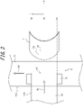
FIG. 2 is a cross-sectional view of the conveying apparatus illustrated inFIG. 1 , taken along a vertical plane passing through a widthwise center of the upstream conveyor; -
FIG. 3 is a top view of the conveying apparatus illustrated inFIG. 1 , without the housing; -
FIG. 4 is a horizontal cross-sectional view of the receiving plate illustrated inFIG. 1 ; -
FIG. 5 is a cross-sectional view along a plane perpendicular to a central axis of the curved-plate-like portion of the receiving plate illustrated inFIG. 1 ; -
FIG. 6 is a top view of a variation of the conveying apparatus illustrated in -
FIG. 1 , without the housing; -
FIG. 7 illustrates a contact angle of water on the curved-plate-like portion; -
FIG. 8 illustrates a contact angle of water on a flat plate; and -
FIG. 9 illustrates the evaluation results of the amount of adhesion on the receiving plate illustrated inFIG. 1 . - Embodiments of the present disclosure will be described below with reference to the accompanying drawings.
- As illustrated in
FIGS. 1 to 5 , in one embodiment of the present disclosure, a receivingplate 1 is configured to change, in atransfer section 6 of abelt conveyor 5 where a conveyedmaterial 2 is dropped from anupstream conveyor 3 and transferred to adownstream conveyor 4, a direction in which the conveyed material fall by receiving the conveyedmaterial 2 dropped from theupstream conveyor 3. In this embodiment, atransfer section chute 7 comprises: ahousing 8 configured to cover thetransfer section 6; and the receivingplate 1 arranged in thehousing 8. Thebelt conveyor 5 includes theupstream conveyor 3 and thedownstream conveyor 4. In this embodiment, thebelt conveyor 5 and thetransfer section chute 7 constitute a conveyingapparatus 9. A conveying method according to this embodiment comprises changing, by the receivingplate 1 provided in thetransfer section 6, a direction in which the conveyedmaterial 2 fall by receiving the conveyedmaterial 2 dropped from theupstream conveyor 3 by the receivingplate 1. In this embodiment, the conveyedmaterial 2 is a water-containing material that has adhesive properties due to the presence of water. For example, the conveyedmaterial 2 is iron ore, coal, or other steelmaking raw material that contains water due to exposure to rain during field loading, and so on. However, the conveyedmaterial 2 is not limited to a water-containing material as long as it has adhesive properties. - The
upstream conveyor 3 includes abelt 10 made of cloth, synthetic resin, rubber, or the like, adriver 1 such as a pulley configured to drive thebelt 10, and aguide 12 such as a roller configured to guide thebelt 10. Thedownstream conveyor 4 includes abelt 13 made of cloth, synthetic resin, rubber, or the like, a driver such as a pulley (not illustrated) configured to drive thebelt 13, and aguide 14 such as a roller configured to guide thebelt 13. InFIG. 1 , theguide 12 of theupstream conveyor 3 and the guide of thedownstream conveyor 4 are not illustrated. Theupstream conveyor 3 has anunloading end 15 that is positioned above thedownstream conveyor 4 in thetransfer section 6. InFIGS. 1 and3 , a conveying direction D1 of theupstream conveyor 3 and a conveying direction D2 of thedownstream conveyor 4 are indicated by white arrows. Either or both of the conveying direction D1 of theupstream conveyor 3 and the conveying direction D2 of thedownstream conveyor 4 may be horizontal or inclined vertically upward or downward from the horizontal. As illustrated inFIG. 3 , the conveying direction D2 of thedownstream conveyor 4 is rotated 90° counterclockwise relative to the conveying direction D1 of theupstream conveyor 3 in top view. However, it may be rotated at any other angle such as 270°, 0°, or 180°. The shape of thehousing 8 of thetransfer section chute 7 may be changed according to this angle. In this embodiment, the up and down directions mean the directions along the vertical direction. - In this embodiment, the X-axis positive direction is the direction that coincides with the conveying direction D1 of the
upstream conveyor 3 in a horizontal plane, the Y-axis positive direction is the direction rotated 90° counterclockwise relative to the X-axis positive direction in top view, and the Z-axis positive direction is the vertical-up direction. - The
housing 8 includes ahousing body 8a made of for example steel material, and twoskirts 8b made of for example synthetic resin or rubber, provided at a lower end of thehousing body 8a, and facing each other in the width direction of the downstream conveyor 4 (i.e., in the X-axis direction). However, the components of thehousing 8 are not so limited. For example, thehousing 8 may not have bothskirts 8b. Thehousing 8 has aninsertion port 16 into which the unloadingend 15 of theupstream conveyor 3 is inserted, and adischarge port 17 configured to discharge the conveyedmaterial 2 toward the upper surface of thedownstream conveyor 4. However, the components of thehousing 8 are not so limited. Thehousing 8 is configured to cover thetransfer section 6 of thebelt conveyor 5, making it possible to prevent the conveyedmaterial 2 from spilling off thebelt conveyor 5 in thetransfer section 6. - The receiving
plate 1 is arranged in thehousing 8. Thehousing 8 has a through-hole 18 through which the receivingplate 1 passes, and the receivingplate 1 is arranged partially within thehousing 8. However, the arrangement of the receivingplate 1 is not so limited. For example, the receivingplate 1 may be arranged entirely within thehousing 8. - The receiving
plate 1 comprises a curved-plate-like portion 19 having a receivingsurface 19a configured to receive the conveyedmaterial 2. The curved-plate-like portion 19 is curved to form a single convex portion facing in an opposite direction from the conveying direction D1 of the upstream conveyor 3 (i.e., facing in the X-axis negative direction) in a horizontal cross section (seeFIG. 4 ). - Accordingly, when the receiving
surface 19a receives the conveyedmaterial 2 that is unloaded in the conveying direction D1 while falling from the unloadingend 15 of theupstream conveyor 3, the repulsive force F2 against the impact force F1 from the conveyedmaterial 2 can be reduced. In other words, since the receivingsurface 19a is inclined at an angle relative to the conveying direction D1 in the horizontal cross section, the repulsive force F2 can be reduced compared to the conventional case where the receivingsurface 19a is perpendicular to the conveying direction D1. The direction of inclination is not in the direction of agglomeration of the conveyedmaterial 2 that hit the receivingsurface 19a, but in the direction of divergence thereof (i.e., one part on the Y-axis positive direction side is inclined in the X-axis positive direction toward the Y-axis positive direction, and the other part on the Y-axis negative direction side is inclined in the X-axis positive direction toward the Y-axis negative direction). - The receiving
surface 19a of the curved-plate-like portion 19 has higher water repellency, i.e., has a larger contact angle to water due to its curved shape, when compared to thesurface 20a of the flat plate 20 (seeFIG. 7 ). In other words, as illustrated inFIGS. 6 to 7 , the contact angle of water at the receivingsurface 19a of the curved-plate-like portion 19, θ1, is larger than the contact angle of water at thesurface 20a of theflat plate 20, θ2. Accordingly, the receivingsurface 19a of the curved-plate-like portion 19 is more difficult for the conveyedmaterial 2 containing water or liquids other than water to adhere to its surface than thesurface 20a of theflat plate 20. - Consequently, the curved-plate-
like portion 19 thus configured can suppress adhesion of the conveyedmaterial 2 to the receivingplate 1. - The materials and methods for forming the receiving
plate 1 are not limited. However, for example, the receivingplate 1 is made of steel and is formed by roller machining of a single sheet of steel. - In this embodiment, the receiving
plate 1 is configured to receive the conveyedmaterial 2 only by the curved-plate-like portion 19. Accordingly, this configuration may efficiently suppress adhesion of the conveyedmaterial 2 to the receivingplate 1. However, the configuration of the receivingplate 1 is not so limited. For example, the receivingplate 1 may be configured to receive the conveyedmaterial 2 by the curved-plate-like portion 19 and two flat-plate-like portions 21, as in a variation illustrated inFIG. 8 . In this variation, the flat-plate-like portions 21 are continuously connected to the respective ends of the curved-plate-like portion 19 in the width direction (i.e., Y-axis direction) of theupstream conveyor 3 in top view. In this variation, the receivingplate 1 is configured to form, as a whole, a single convex portion facing in an opposite direction from the conveying direction D1 of theupstream conveyor 3 in a horizontal cross section. - As illustrated in
FIG. 4 , in this embodiment, the receivingplate 1 is configured to form, as a whole, a single convex portion facing in an opposite direction from the conveying direction D1 of theupstream conveyor 3 in a horizontal cross section. Accordingly, this configuration may suppress adhesion of the conveyedmaterial 2 to the receivingplate 1 in a more efficient way. However, the configuration of the receivingplate 1 is not so limited. - In this embodiment, the curved-plate-
like portion 19 is positioned at least within the width of theupstream conveyor 3 in top view (seeFIG. 3 ). In other words, the curved-plate-like portion 19 is positioned at least between a vertical plane on one widthwise end S1 and a vertical plane on the other widthwise end S2. The vertical plane on one widthwise end S1 is a vertical plane passing through one widthwise end of the upper surface of thebelt 10 on which the conveyedmaterial 2 is placed at the unloadingend 15 of the upstream conveyor 3 (i.e., an end on the Y-axis negative direction side) and extending along the conveying direction D1. The vertical plane on the other widthwise end S2 is a vertical plane passing through the other widthwise end of the upper surface (i.e., an end on the Y-axis positive direction side) and extending along the conveying direction D1. Accordingly, this configuration allows the curved-plate-like portion 19 to receive the conveyedmaterial 2 dropped from theupstream conveyor 3 in a more efficient way. However, the configuration of the receivingplate 1 is not so limited. - In this embodiment, the receiving
surface 19a of the curved-plate-like portion 19 is a cylindrical surface centered on a predetermined axis, for example, a central axis O (seeFIG. 5 ). In other words, the receivingsurface 19a has an arc shape in a cross section perpendicular to the central axis O. Accordingly, this configuration may suppress adhesion of the conveyedmaterial 2 to the receivingplate 1 in a more efficient way. The configuration of the receivingsurface 19a of the curved-plate-like portion 19 is not so limited. For example, the receivingsurface 19a may be an elliptic cylindrical surface centered on the central axis O (i.e., it may have an elliptical arc shape in a cross section perpendicular to the central axis O). - In this embodiment, the central axis O is positioned in a vertical plane on a widthwise center S3 (see
FIG. 3 ), which is a vertical plane passing through the widthwise center of the upstream conveyor 3 (i.e., the center in the Y-axis direction). Accordingly, this configuration allows the curved-plate-like portion 19 to receive the conveyedmaterial 2 dropped from theupstream conveyor 3 in a more efficient way. However, the configuration of the receivingplate 1 is not so limited. - In this embodiment, the receiving
plate 1 is symmetrical about the vertical plane passing through the widthwise center of theupstream conveyor 3, i.e., the vertical plane on the widthwise center S3. Accordingly, the conveyedmaterial 2 dropped from theupstream conveyor 3 can be repelled equally on both sides in the width direction by the receivingsurface 19a of the curved-plate-like portion 19 to be transferred to thedownstream conveyor 4. Consequently, the balance of loading onto thedownstream conveyor 4, which is orthogonal to theupstream conveyor 3, can be improved (i.e., the unevenness of the conveyedmaterial 2 in the width direction of thedownstream conveyor 4 can be reduced). Therefore, the life of thedownstream conveyor 4 can be extended and spillage of the conveyedmaterial 2 from thedownstream conveyor 4 can be reduced. However, the configuration of the receivingplate 1 is not so limited. - The aspect ratio d/w (see
FIG. 5 ) of the receivingsurface 19a of the curved-plate-like portion 19 in a cross section along a plane perpendicular to the central axis O of the curved-plate-like portion 19 can be set appropriately, taking into account the balance of the load on thedownstream conveyor 4 and other factors. Where d is the length of the receivingsurface 19a in the radial direction from the central axis O, and w is the length of the receivingsurface 19a in a direction perpendicular to the radial direction from the central axis O. - The size of an inclination angle β (see
FIG. 2 ) of the receivingplate 1 relative to the vertical direction (i.e., the Z-axis direction), i.e., an angle formed by the central axis O (seeFIG. 5 ) relative to the vertical direction, can be set appropriately, taking into account the balance of the load on thedownstream conveyor 4 and other factors. The receivingplate 1 may be provided with an adjustable inclination angle β. - The above-described embodiments and variations thereof can be modified as needed within the scope of claims.
- As an example of the present disclosure, the effect of the receiving
plates 1 illustrated inFIGS. 1 to 5 on the reduction of the amount of adhesion of the conveyedmaterial 2 was verified by computer simulation. The results are presented inFIG. 9. FIG. 9 illustrates the effect of the present disclosure when the aspect ratio d/w was gradually increased from 0.05 to 0.4 as a ratio relative to a conventional flat receiving plate. Calculation was made with an inclination angle β of 15°. The moisture content of the conveyedmaterial 2 was set to 10 %. It was confirmed that a 10 % improvement was obtained by increasing the aspect ratio d/w to 0.2. -
- 1
- Receiving plate
- 2
- Conveyed material
- 3
- Upstream conveyor
- 4
- Downstream conveyor
- 5
- Belt conveyor
- 6
- Transfer section
- 7
- Transfer section chute
- 8
- Housing
- 8a
- Housing body
- 8b
- Skirt
- 9
- Conveying apparatus
- 10
- Belt
- 11
- Driver
- 12
- Guide
- 13
- Belt
- 14
- Guide
- 15
- Unloading end
- 16
- Insertion port
- 17
- Discharge port
- 18
- Through-hole
- 19
- Curved-plate-like portion
- 19a
- Receiving surface
- 20
- Flat plate
- 20a
- Surface
- 21
- Flat-plate-like portion
- D1, D2
- Conveying direction
- F1
- Collision force
- F2
- Repulsive force
- θ1, θ2
- Contact angle
- S1
- Vertical plane on one widthwise end
- S2
- Vertical plane on other widthwise end
- S3
- Vertical plane on widthwise center
- O
- Central axis
- d
- Length of receiving surface in radial direction from central axis
- w
- Length of receiving surface in direction perpendicular to radial direction from central axis
- β
- Inclination angle
Claims (10)
- A receiving plate provided in a transfer section of a belt conveyor where a conveyed material is dropped from an upstream conveyor and transferred to a downstream conveyor, and configured to change a direction in which the conveyed material fall by receiving the conveyed material dropped from the upstream conveyor, the receiving plate comprising:a curved-plate-like portion having a receiving surface to configured to receive the conveyed material,wherein the curved-plate-like portion is curved to form a single convex portion facing in an opposite direction from a conveying direction of the upstream conveyor in a horizontal cross section.
- The receiving plate according to claim 1, wherein the receiving surface of the curved-plate-like portion is a cylindrical or elliptic cylindrical surface centered on a predetermined axis.
- The receiving plate according to claim 2, wherein the predetermined axis is positioned in a vertical plane passing through a widthwise center of the upstream conveyor.
- The receiving plate according to any one of claims 1 to 3, wherein the conveyed material is received only by the curved-plate-like portion.
- The receiving plate according to any one of claims 1 to 4, wherein the curved-plate-like portion is positioned at least within a width of the upstream conveyor in top view.
- The receiving plate according to any one of claims 1 to 5, being symmetrical about a vertical plane passing through a widthwise center of the upstream conveyor.
- The receiving plate according to any one of claims 1 to 6, configured to form, as a whole, a single convex portion facing in an opposite direction from a conveying direction of the upstream conveyor in a horizontal cross section.
- A transfer section chute comprising:a housing configured to cover a transfer section of a belt conveyor where a conveyed material is dropped from an upstream conveyor and transferred to a downstream conveyor; anda receiving plate arranged in the housing and configured to change a direction in which the conveyed material fall by receiving the conveyed material dropped from the upstream conveyor,wherein the receiving plate comprises a curved-plate-like portion having a receiving surface configured to receive the conveyed material, andwherein the the curved-plate-like portion is curved to form a single convex portion facing in an opposite direction from a conveying direction of the upstream conveyor in a horizontal cross section.
- A conveying apparatus comprising the transfer section chute as recited in claim 8.
- A conveying method comprising changing, by a receiving plate provided in a transfer section of a belt conveyor where a conveyed material is dropped from an upstream conveyor and transferred to a downstream conveyor, a direction in which the conveyed material fall by receiving the conveyed material dropped from the upstream conveyor by the receiving plate,wherein the receiving plate comprises a curved-plate-like portion having a receiving surface configured to receive the conveyed material, andwherein the curved-plate-like section is curved to form a single convex portion facing in an opposite direction from a conveying direction of the upstream conveyor in a horizontal cross section.
Applications Claiming Priority (2)
| Application Number | Priority Date | Filing Date | Title |
|---|---|---|---|
| JP2020020847 | 2020-02-10 | ||
| PCT/JP2021/003417 WO2021161820A1 (en) | 2020-02-10 | 2021-01-29 | Receiving plate, transfer chute, conveying apparatus, and conveying method |
Publications (2)
| Publication Number | Publication Date |
|---|---|
| EP4105148A1 true EP4105148A1 (en) | 2022-12-21 |
| EP4105148A4 EP4105148A4 (en) | 2023-08-02 |
Family
ID=77293002
Family Applications (1)
| Application Number | Title | Priority Date | Filing Date |
|---|---|---|---|
| EP21753494.0A Pending EP4105148A4 (en) | 2020-02-10 | 2021-01-29 | Receiving plate, transfer chute, conveying apparatus, and conveying method |
Country Status (7)
| Country | Link |
|---|---|
| EP (1) | EP4105148A4 (en) |
| JP (1) | JP7248111B2 (en) |
| KR (1) | KR102776335B1 (en) |
| CN (1) | CN114945526A (en) |
| BR (1) | BR112022013907A2 (en) |
| TW (1) | TWI829997B (en) |
| WO (1) | WO2021161820A1 (en) |
Families Citing this family (1)
| Publication number | Priority date | Publication date | Assignee | Title |
|---|---|---|---|---|
| CN120774095A (en) * | 2025-06-23 | 2025-10-14 | 苏州侨芯智能技术发展有限公司 | Uniform material tiling equipment, uniform material feeding system and method |
Family Cites Families (9)
| Publication number | Priority date | Publication date | Assignee | Title |
|---|---|---|---|---|
| JPS531539B2 (en) * | 1972-08-31 | 1978-01-19 | ||
| JPS5517043U (en) * | 1978-07-17 | 1980-02-02 | ||
| JP3171359B2 (en) * | 1993-10-07 | 2001-05-28 | 株式会社ダイフク | Transfer device |
| JPH11189328A (en) | 1997-12-25 | 1999-07-13 | Kawasaki Steel Corp | Conveyance adhesion prevention device at transfer section of belt conveyor |
| JP5452094B2 (en) * | 2009-06-25 | 2014-03-26 | 株式会社三井三池製作所 | Dispenser chute damper device |
| KR101572361B1 (en) * | 2014-02-27 | 2015-11-26 | 현대제철 주식회사 | Damper for raw material chute and raw material having the same |
| CN104860039B (en) * | 2015-04-20 | 2016-05-25 | 四川东林矿山运输机械有限公司 | Controlled bulk material environmental protection transfer system |
| CN105236111A (en) * | 2015-11-05 | 2016-01-13 | 鞍钢集团矿业公司 | Material-receiving plate with adjustable angle for transloading funnel |
| CN209973431U (en) * | 2019-03-29 | 2020-01-21 | 浙江巨化热电有限公司 | Coal breakage pipe anti-blocking device |
-
2021
- 2021-01-29 JP JP2021523770A patent/JP7248111B2/en active Active
- 2021-01-29 KR KR1020227022172A patent/KR102776335B1/en active Active
- 2021-01-29 WO PCT/JP2021/003417 patent/WO2021161820A1/en not_active Ceased
- 2021-01-29 CN CN202180008056.XA patent/CN114945526A/en active Pending
- 2021-01-29 BR BR112022013907A patent/BR112022013907A2/en unknown
- 2021-01-29 EP EP21753494.0A patent/EP4105148A4/en active Pending
- 2021-02-05 TW TW110104359A patent/TWI829997B/en active
Also Published As
| Publication number | Publication date |
|---|---|
| BR112022013907A2 (en) | 2022-09-13 |
| EP4105148A4 (en) | 2023-08-02 |
| CN114945526A (en) | 2022-08-26 |
| TW202134153A (en) | 2021-09-16 |
| TWI829997B (en) | 2024-01-21 |
| JP7248111B2 (en) | 2023-03-29 |
| WO2021161820A1 (en) | 2021-08-19 |
| KR102776335B1 (en) | 2025-03-04 |
| KR20220104249A (en) | 2022-07-26 |
| JPWO2021161820A1 (en) | 2021-08-19 |
Similar Documents
| Publication | Publication Date | Title |
|---|---|---|
| US3910405A (en) | Conveyor apparatus | |
| EP4105148A1 (en) | Receiving plate, transfer chute, conveying apparatus, and conveying method | |
| EP4105149A1 (en) | Receiving plate, transfer chute, conveying apparatus, and conveying method | |
| US5526922A (en) | High lift bucket | |
| US12139341B2 (en) | Trough belt conveyor | |
| CN106743100A (en) | A kind of rib transmission belt | |
| JPS62244809A (en) | belt type bucket elevator | |
| JPH0417853B2 (en) | ||
| CN218138481U (en) | Anti-friction plate of inner layer punching machine and inner layer punching machine | |
| CN219859275U (en) | Belt feed opening anti-blocking device | |
| JP2021155218A (en) | Skirt structure of belt conveyor | |
| CN209939764U (en) | Prevent to dash inclined to one side band conveyer connect material structure | |
| GB2287446A (en) | Conveying means with material transfer between two conveyors | |
| CN202054376U (en) | Steel wire rope core flange conveyer belt | |
| JP2753859B2 (en) | Belt conveyor device | |
| CN212333667U (en) | Chute device | |
| CN208948231U (en) | A kind of idler for belt conveyer group | |
| CN211003177U (en) | Novel antiskid super-lifting conveying device | |
| JP2018135209A (en) | Carrier apparatus | |
| JP2001199519A (en) | Belt conveyer device | |
| CN121158551A (en) | Stock guide with refining function and look selection machine of using thereof | |
| JP2018054219A (en) | Rotary dryer conveyor and conveyor cover | |
| CN206172470U (en) | Dam device and be equipped with this dam device's belt conveyor | |
| CN117772607A (en) | An air separator | |
| JPH08198453A (en) | Vertical belt conveyor feeder |
Legal Events
| Date | Code | Title | Description |
|---|---|---|---|
| STAA | Information on the status of an ep patent application or granted ep patent |
Free format text: STATUS: THE INTERNATIONAL PUBLICATION HAS BEEN MADE |
|
| PUAI | Public reference made under article 153(3) epc to a published international application that has entered the european phase |
Free format text: ORIGINAL CODE: 0009012 |
|
| STAA | Information on the status of an ep patent application or granted ep patent |
Free format text: STATUS: REQUEST FOR EXAMINATION WAS MADE |
|
| 17P | Request for examination filed |
Effective date: 20220708 |
|
| AK | Designated contracting states |
Kind code of ref document: A1 Designated state(s): AL AT BE BG CH CY CZ DE DK EE ES FI FR GB GR HR HU IE IS IT LI LT LU LV MC MK MT NL NO PL PT RO RS SE SI SK SM TR |
|
| DAV | Request for validation of the european patent (deleted) | ||
| DAX | Request for extension of the european patent (deleted) | ||
| A4 | Supplementary search report drawn up and despatched |
Effective date: 20230629 |
|
| RIC1 | Information provided on ipc code assigned before grant |
Ipc: B65G 47/53 20060101ALI20230623BHEP Ipc: B65G 47/44 20060101ALI20230623BHEP Ipc: B65G 11/00 20060101AFI20230623BHEP |
|
| STAA | Information on the status of an ep patent application or granted ep patent |
Free format text: STATUS: EXAMINATION IS IN PROGRESS |
|
| 17Q | First examination report despatched |
Effective date: 20250319 |