EP4105005A1 - Three-dimensional textile preforms and method for their manufacture - Google Patents
Three-dimensional textile preforms and method for their manufacture Download PDFInfo
- Publication number
- EP4105005A1 EP4105005A1 EP22179462.1A EP22179462A EP4105005A1 EP 4105005 A1 EP4105005 A1 EP 4105005A1 EP 22179462 A EP22179462 A EP 22179462A EP 4105005 A1 EP4105005 A1 EP 4105005A1
- Authority
- EP
- European Patent Office
- Prior art keywords
- textile preform
- wall portion
- preform
- textile
- flange portion
- Prior art date
- Legal status (The legal status is an assumption and is not a legal conclusion. Google has not performed a legal analysis and makes no representation as to the accuracy of the status listed.)
- Granted
Links
Images



Classifications
-
- B—PERFORMING OPERATIONS; TRANSPORTING
- B29—WORKING OF PLASTICS; WORKING OF SUBSTANCES IN A PLASTIC STATE IN GENERAL
- B29C—SHAPING OR JOINING OF PLASTICS; SHAPING OF MATERIAL IN A PLASTIC STATE, NOT OTHERWISE PROVIDED FOR; AFTER-TREATMENT OF THE SHAPED PRODUCTS, e.g. REPAIRING
- B29C70/00—Shaping composites, i.e. plastics material comprising reinforcements, fillers or preformed parts, e.g. inserts
- B29C70/04—Shaping composites, i.e. plastics material comprising reinforcements, fillers or preformed parts, e.g. inserts comprising reinforcements only, e.g. self-reinforcing plastics
- B29C70/06—Fibrous reinforcements only
- B29C70/10—Fibrous reinforcements only characterised by the structure of fibrous reinforcements, e.g. hollow fibres
- B29C70/16—Fibrous reinforcements only characterised by the structure of fibrous reinforcements, e.g. hollow fibres using fibres of substantial or continuous length
- B29C70/22—Fibrous reinforcements only characterised by the structure of fibrous reinforcements, e.g. hollow fibres using fibres of substantial or continuous length oriented in at least two directions forming a two-dimensional [2D] structure
- B29C70/222—Fibrous reinforcements only characterised by the structure of fibrous reinforcements, e.g. hollow fibres using fibres of substantial or continuous length oriented in at least two directions forming a two-dimensional [2D] structure the structure being shaped to form a three dimensional configuration
-
- B—PERFORMING OPERATIONS; TRANSPORTING
- B64—AIRCRAFT; AVIATION; COSMONAUTICS
- B64C—AEROPLANES; HELICOPTERS
- B64C3/00—Wings
- B64C3/18—Spars; Ribs; Stringers
- B64C3/182—Stringers, longerons
-
- B—PERFORMING OPERATIONS; TRANSPORTING
- B29—WORKING OF PLASTICS; WORKING OF SUBSTANCES IN A PLASTIC STATE IN GENERAL
- B29B—PREPARATION OR PRETREATMENT OF THE MATERIAL TO BE SHAPED; MAKING GRANULES OR PREFORMS; RECOVERY OF PLASTICS OR OTHER CONSTITUENTS OF WASTE MATERIAL CONTAINING PLASTICS
- B29B11/00—Making preforms
- B29B11/14—Making preforms characterised by structure or composition
- B29B11/16—Making preforms characterised by structure or composition comprising fillers or reinforcement
-
- B—PERFORMING OPERATIONS; TRANSPORTING
- B29—WORKING OF PLASTICS; WORKING OF SUBSTANCES IN A PLASTIC STATE IN GENERAL
- B29C—SHAPING OR JOINING OF PLASTICS; SHAPING OF MATERIAL IN A PLASTIC STATE, NOT OTHERWISE PROVIDED FOR; AFTER-TREATMENT OF THE SHAPED PRODUCTS, e.g. REPAIRING
- B29C70/00—Shaping composites, i.e. plastics material comprising reinforcements, fillers or preformed parts, e.g. inserts
- B29C70/04—Shaping composites, i.e. plastics material comprising reinforcements, fillers or preformed parts, e.g. inserts comprising reinforcements only, e.g. self-reinforcing plastics
- B29C70/06—Fibrous reinforcements only
- B29C70/10—Fibrous reinforcements only characterised by the structure of fibrous reinforcements, e.g. hollow fibres
- B29C70/16—Fibrous reinforcements only characterised by the structure of fibrous reinforcements, e.g. hollow fibres using fibres of substantial or continuous length
- B29C70/24—Fibrous reinforcements only characterised by the structure of fibrous reinforcements, e.g. hollow fibres using fibres of substantial or continuous length oriented in at least three directions forming a three-dimensional [3D] structure
-
- B—PERFORMING OPERATIONS; TRANSPORTING
- B29—WORKING OF PLASTICS; WORKING OF SUBSTANCES IN A PLASTIC STATE IN GENERAL
- B29C—SHAPING OR JOINING OF PLASTICS; SHAPING OF MATERIAL IN A PLASTIC STATE, NOT OTHERWISE PROVIDED FOR; AFTER-TREATMENT OF THE SHAPED PRODUCTS, e.g. REPAIRING
- B29C70/00—Shaping composites, i.e. plastics material comprising reinforcements, fillers or preformed parts, e.g. inserts
- B29C70/68—Shaping composites, i.e. plastics material comprising reinforcements, fillers or preformed parts, e.g. inserts by incorporating or moulding on preformed parts, e.g. inserts or layers, e.g. foam blocks
- B29C70/681—Component parts, details or accessories; Auxiliary operations
- B29C70/682—Preformed parts characterised by their structure, e.g. form
-
- B—PERFORMING OPERATIONS; TRANSPORTING
- B29—WORKING OF PLASTICS; WORKING OF SUBSTANCES IN A PLASTIC STATE IN GENERAL
- B29D—PRODUCING PARTICULAR ARTICLES FROM PLASTICS OR FROM SUBSTANCES IN A PLASTIC STATE
- B29D99/00—Subject matter not provided for in other groups of this subclass
- B29D99/0003—Producing profiled members, e.g. beams
-
- B—PERFORMING OPERATIONS; TRANSPORTING
- B29—WORKING OF PLASTICS; WORKING OF SUBSTANCES IN A PLASTIC STATE IN GENERAL
- B29D—PRODUCING PARTICULAR ARTICLES FROM PLASTICS OR FROM SUBSTANCES IN A PLASTIC STATE
- B29D99/00—Subject matter not provided for in other groups of this subclass
- B29D99/001—Producing wall or panel-like structures, e.g. for hulls, fuselages, or buildings
- B29D99/0014—Producing wall or panel-like structures, e.g. for hulls, fuselages, or buildings provided with ridges or ribs, e.g. joined ribs
-
- B—PERFORMING OPERATIONS; TRANSPORTING
- B29—WORKING OF PLASTICS; WORKING OF SUBSTANCES IN A PLASTIC STATE IN GENERAL
- B29K—INDEXING SCHEME ASSOCIATED WITH SUBCLASSES B29B, B29C OR B29D, RELATING TO MOULDING MATERIALS OR TO MATERIALS FOR MOULDS, REINFORCEMENTS, FILLERS OR PREFORMED PARTS, e.g. INSERTS
- B29K2105/00—Condition, form or state of moulded material or of the material to be shaped
- B29K2105/06—Condition, form or state of moulded material or of the material to be shaped containing reinforcements, fillers or inserts
- B29K2105/08—Condition, form or state of moulded material or of the material to be shaped containing reinforcements, fillers or inserts of continuous length, e.g. cords, rovings, mats, fabrics, strands or yarns
- B29K2105/0809—Fabrics
- B29K2105/0845—Woven fabrics
-
- B—PERFORMING OPERATIONS; TRANSPORTING
- B29—WORKING OF PLASTICS; WORKING OF SUBSTANCES IN A PLASTIC STATE IN GENERAL
- B29K—INDEXING SCHEME ASSOCIATED WITH SUBCLASSES B29B, B29C OR B29D, RELATING TO MOULDING MATERIALS OR TO MATERIALS FOR MOULDS, REINFORCEMENTS, FILLERS OR PREFORMED PARTS, e.g. INSERTS
- B29K2105/00—Condition, form or state of moulded material or of the material to be shaped
- B29K2105/25—Solid
- B29K2105/253—Preform
-
- B—PERFORMING OPERATIONS; TRANSPORTING
- B29—WORKING OF PLASTICS; WORKING OF SUBSTANCES IN A PLASTIC STATE IN GENERAL
- B29L—INDEXING SCHEME ASSOCIATED WITH SUBCLASS B29C, RELATING TO PARTICULAR ARTICLES
- B29L2031/00—Other particular articles
- B29L2031/30—Vehicles, e.g. ships or aircraft, or body parts thereof
- B29L2031/3076—Aircrafts
- B29L2031/3085—Wings
-
- Y—GENERAL TAGGING OF NEW TECHNOLOGICAL DEVELOPMENTS; GENERAL TAGGING OF CROSS-SECTIONAL TECHNOLOGIES SPANNING OVER SEVERAL SECTIONS OF THE IPC; TECHNICAL SUBJECTS COVERED BY FORMER USPC CROSS-REFERENCE ART COLLECTIONS [XRACs] AND DIGESTS
- Y02—TECHNOLOGIES OR APPLICATIONS FOR MITIGATION OR ADAPTATION AGAINST CLIMATE CHANGE
- Y02T—CLIMATE CHANGE MITIGATION TECHNOLOGIES RELATED TO TRANSPORTATION
- Y02T50/00—Aeronautics or air transport
- Y02T50/40—Weight reduction
Definitions
- Vehicles include many different structural components that are under force during use.
- skin panels of an aircraft form a surface that is acted upon by aerodynamic forces during flight.
- the aircraft includes structures configured to reinforce the skin panels and impart aerodynamic forces acting upon the skin panels to load-bearing support structures.
- structures referred to as "stringers” are used to stiffen skin panels and transmit aerodynamic forces acting upon the skin panels to load-bearing structures such as spars and/or ribs.
- These stiffeners can take various forms. As examples, some stiffeners have a blade-shaped cross section with a flange and a web, while others have a hollow interior and a cross-sectional shape akin to a top hat.
- one or more structural components are made from composite materials, such as a carbon fiber/epoxy system.
- skin and stiffeners are formed as a unitary structure by bonding, co-curing or infusing the skin and stiffeners together.
- a fiber layer used in a composite part can have limits on formability, such as a minimum radius of curvature to which it can be bent without damaging the fiber, introducing defects into the composite part, creating a void (e.g., a deltoid) at the radius, or distorting surrounding material.
- Radius fillers can be employed at intersections between surfaces where the fiber layer is bent, thereby preventing distortion in the surrounding material as it transitions from one surface to another.
- a three-dimensional (3D) textile preform for a composite part comprises a flange portion and a stiffener portion extending upwardly from the flange portion.
- the stiffener portion comprises a first wall portion that extends from the flange portion and a second wall portion that extends from the flange portion at a location spaced from the first wall portion.
- a connecting portion connects the first wall portion and the second wall portion at a location spaced from the flange portion.
- a composite part for a vehicle comprises a composite skin comprising one or more material layers.
- a composite load-bearing structure is coupled to the composite skin.
- the composite load-bearing structure comprises a 3D textile preform.
- the 3D textile preform comprises a flange portion adjacent to the one or more material layers of the composite skin.
- a stiffener portion extends upwardly from the flange portion.
- the stiffener portion comprises a first wall portion that extends from the flange portion and a second wall portion that extends from the flange portion at a location spaced from the first wall portion.
- a connecting portion connects the first wall portion and the second wall portion at a location spaced from the flange portion.
- the composite part further comprises a cured polymer matrix at least partially surrounding the one or more material layers of the composite skin and the 3D textile preform.
- a vehicle comprises a composite part.
- the composite part comprises a composite skin comprising one or more material layers and a composite load-bearing structure coupled to the composite skin.
- the composite load-bearing structure comprises a 3D textile preform.
- the 3D textile preform comprises a flange portion adjacent to the one or more material layers of the composite skin.
- a stiffener portion extends upwardly from the flange portion.
- the stiffener portion comprises a first wall portion that extends from the flange portion and a second wall portion that extends from the flange portion at a location spaced from the first wall portion.
- a connecting portion connects the first wall portion and the second wall portion at a location spaced from the flange portion.
- the composite part further comprises a cured polymer matrix at least partially surrounding the one or more material layers of the composite skin and the 3D textile preform.
- a method of forming a 3D textile preform for a composite part comprises weaving or braiding a 3D textile.
- the 3D textile comprises a flange portion and a stiffener portion extending upwardly from the flange portion.
- the stiffener portion comprises a first wall portion that extends from the flange portion.
- a second wall portion extends from the flange portion at a location spaced from the first wall portion.
- a connecting portion connects the first wall portion and the second wall portion at a location spaced from the flange portion.
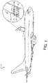
- FIG. 1 shows one example of a vehicle in the form of an aircraft 100 comprising composite parts.
- the vehicle can take the form of a ground-based vehicle (e.g., a car or truck), a drone, a surface watercraft, a submarine, a spacecraft, or any other suitable vehicle.
- a ground-based vehicle e.g., a car or truck
- drone e.g., a drone
- surface watercraft e.g., a surface watercraft
- submarine e.g., a spacecraft
- spacecraft e.g., a spacecraft
- the aircraft 100 includes a wing 102.
- the wing 102 comprises a framework of load-bearing components, including a plurality of frame components 104 and stiffeners in the form of stringers 106.
- the stringers 106 stiffen a lower skin 108 of the aircraft and transfer loads from the skin 108 to the frame components 104 to distribute loads throughout the aircraft 100.
- the skin 108, the stringers 106, and/or any other suitable components of the aircraft 100 are formed from composite materials.
- the skin 108 and one or more stiffeners e.g., stringers 106 are formed as a unitary composite structure by constructing a preform that includes the skin and the one or more stiffeners, infusing the preform with liquid resin, and curing the parts together.
- a composite skin and composite stiffener can be formed and cured separately, and then joined after both parts are cured.
- a potentially complex composite part can pose various challenges. For example, as mentioned above, some fiber layers for use in composites have limits regarding how tight of an angle can be formed by the fiber layer, requiring a radiused bend to be used where the fiber layer changes direction. Introducing a radius between two or more components of a stiffener can result in an open or enclosed void, also referred to a deltoid, in the resulting composite part.
- the deltoid can be strengthened by packing the void with a filler material, such as a "noodle" (an elongated filler shaped to fit the void).
- a technical effect of embodiments herein includes reduced costs and manufacturing steps compared to traditional forming techniques by avoiding the use of a noodle or other filler that can comprise a different material than the rest of the composite part.
- a filler can add weight, and require modifications to cure cycles, processing temperatures and/or pressures
- other technical effects of embodiments herein include reduced weight and manufacturing times.
- Yet other technical effects include avoiding the matching of coefficients of thermal expansion, stiffnesses, and/or other properties compared to the use of fillers.
- a 3D textile preform according to the present disclosure comprises a flange portion and a stiffener portion extending upwardly from the flange portion.
- the stiffener portion comprises a first wall portion that extends from the flange portion and a second wall portion that extends from the flange portion at a location spaced from the first wall portion.
- a connecting portion connects the first wall portion and the second wall portion at a location spaced from the flange portion.
- the stiffener portion further comprises a web portion extending from the connecting portion, with a bulb portion located at a distal end of the web.
- 3D textile preforms allows for the convenient fabrication of complex composite parts in a time and cost-saving manner compared to the use of individual fiber layers.
- a 3D textile preform having a complex shape can be formed as a unitary structure using a single pass on a weaving or braiding apparatus.
- the 3D textile preform can be formed in curved shapes without wrinkling.
- the 3D textile preform can be formed without introducing voids (e.g., a deltoid) in the structure, obviating the use of a noodle or other filler materials.
- a 3D textile preform can be woven, e.g., using orthogonal 3D weaving techniques, or braided.
- a 3D woven structure a set of warp fibers, weft fibers, and binder fibers are interlaced in three dimensions.
- the warp fibers and weft fibers form each of a plurality of two-dimensional layers (e.g., in the XY plane), while the binder fibers interlace the structure in a through-thickness (e.g., Z-axis) direction.
- three or more sets of yarn are inter-plaited.
- stitching in which two-dimensional textile layers are joined together by a sewing process utilizing a needle weaving or braiding can allow all parts of a complex 3D textile preform to be made integral to a single structure without stitching layers together with a needle. Nevertheless, stitching also can be used to form a 3D textile preform in some examples by stitching together multiple two-dimensional (2D) fiber layers.
- a preform for a stringer is formed by 3D textile manufacturing processes.
- fabricating a 3D textile preform does not introduce voids (e.g., a deltoid) in the structure, thereby allowing the omission of a noodle or other filler.
- voids e.g., a deltoid
- the absence of voids can increase resistance to delamination and interlaminar fracturing, and increase tolerance to tensile strain.
- the 3D textile preform renders the composite part more resistant to ballistic and impact damage than a similarly shaped laminar composite.
- FIG. 2 shows a perspective view of an example of a composite part 200 according to the present disclosure.
- the composite part 200 in the illustrated example is a stringer, but as mentioned above, the composite part 200 can be any other suitable part of a vehicle.
- the composite part 200 comprises a composite skin 202 and a composite load-bearing structure 204.
- the composite skin 202 comprises one or more fiber layers contained within a hardened resin matrix and can be formed from any suitable materials. Examples of suitable fiber materials include carbon fiber, fiberglass, polyimide fibers, aramid fibers, basalt, and polypropylene fibers.
- the composite skin 202 comprises two or more different fiber materials.
- suitable resin materials include epoxies, bis-maleimides (BMI), benzoxazines, phenolics, polyimides, phthalonitrile, other thermoplastic or thermosetting resins or adhesives, and combinations thereof.
- the composite load-bearing structure 204 comprises a 3D textile preform (schematically depicted at 300) contained within a hardened resin matrix, instead of individual layers of fiber material.
- the 3D textile preform 300 is described in more detail below with reference to FIG. 3 .
- the depicted example composite load-bearing structure comprises a flange 205 and a stiffener 209 extending upwardly from the flange 205.
- the flange 205 is secured to the composite skin 202.
- the flange 205 is secured to the composite skin by co-infusion of the 3D preform 300 of the composite load-bearing structure 204 and a preform for the skin 202.
- the flange 205 is secured to the skin after forming the composite load-bearing structure 204 and the skin 202 separately.
- the composite load-bearing structure further comprises a first wall 210, a second wall 212, and a connector 214 extending between the first wall 210 and the second wall 212.
- the first wall 210, the second wall 212, and the connector 214 define a channel 220 above the flange 205.
- the channel extends through the composite structure along a long dimension of the structure (e.g., the y-axis direction, which corresponds to a length of a stringer).
- other structures e.g., vehicle components or systems, for example wires
- can be routed inside the channel e.g., to and through), which can help free space outside of the composite part and potentially reduce weight and other stresses applied to the composite part.
- the composite load-bearing structure further comprises a web 216 extending from the connector 214.
- the web 216 comprises a bulb 218 at a distal end, which can help strengthen the stiffener by increasing a mass of the web.
- FIG. 3 shows an end view of the 3D textile preform 300 of FIG. 2 .
- the 3D textile preform 300 is infused with a resin matrix and joined with a composite skin (either by co-infusion or joined after resin infusion) to form a composite load-bearing structure.
- the 3D textile preform 300 comprises a flange portion 302 and a stiffener portion 304.
- the flange portion 302 when infused with a resin matrix that is cured or otherwise hardened, forms a flange within a composite load-bearing structure.
- the stiffener portion 304 forms a stiffener within the composite load-bearing structure.
- the stiffener portion 304 comprises a first wall portion 306 and a second wall portion 308 that extend from the flange portion 302.
- the flange portion 302 and the stiffener portion 304 are integrally formed.
- the illustrated example is devoid of deltoids where the first wall portion 306 and the second wall portion 308 meet the flange portion 302.
- the 3D textile preform 300 comprises a plurality of warp fibers 322, a plurality of weft fibers 324, and a plurality of binder fibers 326.
- each of the warp fibers 322, the weft fibers 324, and the binder fibers 326 comprises a carbon fiber yarn.
- the fibers comprise any other suitable material, examples of which include yarns formed from glass fibers, polyimide fibers, aramid fibers, basalt, and polypropylene fibers.
- the warp fibers 322, the weft fibers 324, or the binder fibers 326 comprise two or more different materials.
- the term "fiber" as used herein represents any fibrous material used in a 3D textile.
- the 3D textile preform 300 can be braided or sewn, rather than woven.
- the warp fibers 322 and the weft fibers 324 are orthogonal to each other but can have any other suitable relative orientation in other examples.
- the binder fibers 326 interlace with the warp fibers 322 and the weft fibers 324 in a through-thickness direction.
- mode I interlaminar fracture toughness and crack propagation values were increased up to 20 times over two-dimensional reinforced epoxy laminates as measured using ASTM standard test method D5528-13.
- the interlaced binder fibers 326 also help to increase strength between layers of the warp fibers 322 and the weft fibers 324, which can increase impact resistance relative to laminar composites (e.g., as determined by compression after impact (CAI); ASTM standard test method D7137).
- the warp fibers 322, weft fibers 324, and binder fibers 326 can form a mesh structure that can be bent or stretched to an extent after the 3D textile preform is fabricated without damaging the preform or introducing wrinkles. Further, as mentioned above, a 3D textile preform can be formed in shapes that can pose difficulties for conventional 2D fiber sheets.
- FIG. 4 shows a 3D textile preform 400 formed to have curvature along its length.
- curvature also can be imparted to a straight preform in some examples.
- forming such a structure with conventional 2D fiber sheets can cause the sheets to wrinkle.
- the 3D textile preform 300 comprises radii where the first wall portion 306 meets the flange portion 302 and where the second wall portion 308 meets the flange portion 302. More specifically, the 3D textile preform 300 comprises a first internal radius 328 between the first wall portion 306 and the flange portion 302, located on an internal side of the stiffener portion that faces the second wall portion 308. The 3D textile preform 300 further comprises a first external radius 330 between the first wall portion 306 and the flange portion 302. The first external radius 330 is located on an external side of the stiffener portion that faces away from the second wall portion 308. The first internal radius 328 and the first external radius 330 help to distribute force where the first wall portion 306 meets the flange portion 302.
- the 3D textile preform 300 comprises a second internal radius 332 between the second wall portion 308 and the flange portion 302.
- the second internal radius 332 is located on an internal side of the stiffener portion that faces the first wall portion 306.
- a second external radius 334 is located between the second wall portion 308 and the flange portion 302 on an external side of the stiffener portion that faces away from the first wall portion 306.
- the second internal radius 332 and the second external radius 334 help to distribute force where the second wall portion 308 meets the flange portion 302. With both the external and internal radii where wall portions meet the flange portion, no deltoids exist where the flange portions and web portion meet.
- the second wall portion 308 is spaced from the first wall portion 306 at distal ends of the wall portions.
- a connecting portion 336 connects the first wall portion 306 and the second wall portion 308 at the distal ends of the wall portions.
- the first wall portion 306, the second wall portion 308, and the connecting portion 336 define a channel 338 above the flange portion 302.
- the channel 338 extends through the 3D textile preform 300 along a long dimension of the preform (e.g., the y-axis direction, which corresponds to a length of a stringer).
- the channel 338 is enclosed by the flange portion 302, the first wall portion 306, the second wall portion 308, and the connecting portion 336 along the length of the 3D textile preform but is open at both ends of the 3D textile preform.
- the channel can be enclosed at the ends of the 3D textile preform and/or include one or more openings along the length of the preform.
- one or more vehicle systems can be installed within the channel 338.
- one or more electrical cables, fuel and/or other fluid lines, pneumatic tubing, and/or mechanical parts (e.g., manual control cables) of an aircraft can be routed through the channel.
- the composite part formed from the preform 300 can help to protect any components that are routed through the channel.
- components can be routed through the channel that would otherwise be attached to an exterior portion of the composite part (e.g., via clips or brackets), reducing weight and other stresses applied to the composite part and freeing space outside of the composite part.
- the channel can be hermetically sealed and/or vaporproof, allowing fluids and/or gasses (e.g., jet fuel or nitrogen gas) to be directly transferred through the channel.
- the first wall portion 306, the second wall portion 308, and the connecting portion 336 together comprise a top-hat cross-section.
- the 3D textile preform can have any other suitable cross-sectional shape.
- FIG. 5 shows another example of a 3D textile preform 500 comprising an elliptical channel.
- the 3D textile preform 500 comprises a flange portion 502 and a stiffener portion 504 extending upwardly from the flange portion 502.
- the stiffener portion 504 comprises a first wall portion 506 and a second wall portion 508 that extend from the flange portion 502.
- the first wall portion 506 and the second wall portion 508 are joined at a connecting portion 510 of the 3D textile preform 500.
- the first wall portion 506, the second wall portion 508, and the connecting portion 510 form an elliptical channel 512 above the flange portion 502.
- the 3D textile preform 300 further comprises a web portion 340 extending from the connecting portion 336.
- the web portion 340 extends from the top of the connecting portion 336 in the positive Z-axis direction.
- FIG. 3 shows a height 342 of the web portion 340 above the connecting portion 336 of the 3D textile preform.
- the height 342 is in a range of 0.01 to 6.0 inches. In other examples, the height 342 is in a range of 0.03 to 4.8 inches. In yet other examples, the height 342 is in a range of 2.0 to 3.0 inches. It will also be appreciated that the height 342 can have any other suitable value.
- the web portion 340 comprises a consistent thickness 344 (e.g., 0.3 inches) along at least a portion of its height.
- the height 342 and the thickness 344 of the web portion 340 both contribute to a stiffness (e.g., as defined by the product EI of Young's modulus (E) and the second moment of area (I)) of the composite part formed from the preform 300.
- the thickness 344 is in a range of 0.01 to 6.0 inches. In other examples, the thickness 344 is in a range of 0.03 to 1.0 inches. In yet other examples, the thickness 344 is in a range of 0.1 to 0.5 inches. In other examples, the thickness 344 can have any other suitable value.
- the web portion comprises a thickness that varies along its height.
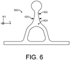
- FIG. 6 shows another example of a 3D textile preform 600 comprising a tapered web portion 602. Like the web portion 340 of FIG. 3 , the tapered web portion 602 extends from a connecting portion 604 of the 3D textile preform 600. However, the tapered web portion 602 comprises a thickness 606 that decreases as a function of distance from the connecting portion 604.
- the 3D textile preform 300 further comprises a bulb portion 346 located at a distal end of the web portion 340, opposite to the connecting portion 336.
- the bulb portion 346 increases a mass of the stiffener portion 304 of the 3D textile preform, and thereby increases stiffness of the resulting composite part.
- the stiffness of the composite part is increased without increasing the height 342 of the web portion 340. In this manner, the composite part formed from the preform 300 can be able to fit within confined spaces, such as inside of a small aircraft.
- the bulb portion 346 further increases damage tolerance of the composite part formed from the preform 300. For example, impact forces can be dissipated by the bulb portion 346, which can help to prevent delamination and other damage that could potentially occur in a laminar composite structure. In addition, an impact can leave a visible mark on a surface of the bulb portion 346, thereby making it easy to identify and assess the effects of any damage sustained.
- the bulb portion 346 comprises an elliptical shape.
- the elliptical bulb portion can dissipate impact forces received from any angle around the bulb.
- the bulb portion 346 comprises a radius of 0.01 to 3.0 inches.
- the radius is in a range of 0.03 to 0.6 inches.
- the radius is in a range of 0.3 to 0.5 inches.
- the bulb portion 346 comprises any other suitable radius.
- a bulb portion can have any other suitable shape.
- the web thickness 344, the web height 342, the bulb radius, and/or any other suitable dimension of the 3D textile preform 300 can be tailored to meet one or more mechanical, thermal, or design specifications for a vehicle.
- the dimensions of the 3D textile preform 300 can be determined based on a size of an aircraft, the aircraft's wing length, fuselage curvature, etc. In some examples, these dimensions are determined using a computational algorithm.
- FIG. 7 illustrates a flow diagram depicting an example method 700 of forming a 3D textile preform for a composite part. It will be appreciated that the following description of method 700 is provided by way of example and is not meant to be limiting. It will be understood that various steps of method 700 can be omitted or performed in a different order than described, and that the method 700 can include additional and/or alternative steps relative to those illustrated in FIG. 7 without departing from the scope of this disclosure.
- the method 700 includes forming a 3D textile preform.
- the 3D textile preform comprises a flange portion and a stiffener portion extending upwardly from the flange portion.
- the stiffener portion comprises a first wall portion that extends from the flange portion.
- a second wall portion extends from the flange portion at a location spaced from the first wall portion.
- a connecting portion connects the first wall portion and the second wall portion at a location spaced from the flange portion.
- forming the 3D textile preform can comprise weaving or braiding the 3D textile preform.
- forming the 3D textile preform can include sewing the 3D textile preform or forming the 3D textile preform using any other suitable technique.
- the method 700 optionally includes forming a web portion extending from the connecting portion. In some such examples, as indicated at 708, the method 700 includes forming a bulb portion located at a distal end of the web portion.
- the method 700 includes, at 710, at least partially surrounding the 3D textile with a liquid resin.
- the method 700 includes curing or otherwise hardening the liquid resin to form a polymer matrix, thereby forming a composite part from the 3D textile preform.
- the composite part can comprise at least a portion of a stringer or any other suitable part.
- 3D textile preforms can allow for the convenient fabrication of complex composite parts in a time and cost-saving manner compared to the use of individual fiber layers, which can require more complex and time-consuming lay-up.
- a composite part can be formed without introducing voids, thereby increasing resistance to delamination and interlaminar fracturing relative to a similarly shaped laminar composite without having to use a void filler, such as a noodle.
Landscapes
- Engineering & Computer Science (AREA)
- Mechanical Engineering (AREA)
- Chemical & Material Sciences (AREA)
- Composite Materials (AREA)
- Textile Engineering (AREA)
- Aviation & Aerospace Engineering (AREA)
- Architecture (AREA)
- Civil Engineering (AREA)
- Structural Engineering (AREA)
- Moulding By Coating Moulds (AREA)
Abstract
Description
- Vehicles include many different structural components that are under force during use. For example, skin panels of an aircraft form a surface that is acted upon by aerodynamic forces during flight. As such, the aircraft includes structures configured to reinforce the skin panels and impart aerodynamic forces acting upon the skin panels to load-bearing support structures. For example, structures referred to as "stringers" are used to stiffen skin panels and transmit aerodynamic forces acting upon the skin panels to load-bearing structures such as spars and/or ribs. These stiffeners can take various forms. As examples, some stiffeners have a blade-shaped cross section with a flange and a web, while others have a hollow interior and a cross-sectional shape akin to a top hat.
- In some vehicles, one or more structural components are made from composite materials, such as a carbon fiber/epoxy system. In such vehicles, skin and stiffeners are formed as a unitary structure by bonding, co-curing or infusing the skin and stiffeners together. However, forming such unitary composite parts can pose various challenges. For example, a fiber layer used in a composite part can have limits on formability, such as a minimum radius of curvature to which it can be bent without damaging the fiber, introducing defects into the composite part, creating a void (e.g., a deltoid) at the radius, or distorting surrounding material. Radius fillers can be employed at intersections between surfaces where the fiber layer is bent, thereby preventing distortion in the surrounding material as it transitions from one surface to another.
- To address the above issues, according to one aspect of the present disclosure, a three-dimensional (3D) textile preform for a composite part comprises a flange portion and a stiffener portion extending upwardly from the flange portion. The stiffener portion comprises a first wall portion that extends from the flange portion and a second wall portion that extends from the flange portion at a location spaced from the first wall portion. A connecting portion connects the first wall portion and the second wall portion at a location spaced from the flange portion.
- According to another aspect of the present disclosure, a composite part for a vehicle comprises a composite skin comprising one or more material layers. A composite load-bearing structure is coupled to the composite skin. The composite load-bearing structure comprises a 3D textile preform. The 3D textile preform comprises a flange portion adjacent to the one or more material layers of the composite skin. A stiffener portion extends upwardly from the flange portion. The stiffener portion comprises a first wall portion that extends from the flange portion and a second wall portion that extends from the flange portion at a location spaced from the first wall portion. A connecting portion connects the first wall portion and the second wall portion at a location spaced from the flange portion. The composite part further comprises a cured polymer matrix at least partially surrounding the one or more material layers of the composite skin and the 3D textile preform.
- According to another aspect of the present disclosure, a vehicle comprises a composite part. The composite part comprises a composite skin comprising one or more material layers and a composite load-bearing structure coupled to the composite skin. The composite load-bearing structure comprises a 3D textile preform. The 3D textile preform comprises a flange portion adjacent to the one or more material layers of the composite skin. A stiffener portion extends upwardly from the flange portion. The stiffener portion comprises a first wall portion that extends from the flange portion and a second wall portion that extends from the flange portion at a location spaced from the first wall portion. A connecting portion connects the first wall portion and the second wall portion at a location spaced from the flange portion. The composite part further comprises a cured polymer matrix at least partially surrounding the one or more material layers of the composite skin and the 3D textile preform.
- According to another aspect of the present disclosure, a method of forming a 3D textile preform for a composite part comprises weaving or braiding a 3D textile. The 3D textile comprises a flange portion and a stiffener portion extending upwardly from the flange portion. The stiffener portion comprises a first wall portion that extends from the flange portion. A second wall portion extends from the flange portion at a location spaced from the first wall portion. A connecting portion connects the first wall portion and the second wall portion at a location spaced from the flange portion.
- The features, functions, and advantages that have been discussed can be achieved independently in various embodiments or can be combined in yet other embodiments, further details of which can be seen with reference to the following description and drawings.
-
-
FIG. 1 shows an example of a vehicle according to the present disclosure. -
FIG. 2 shows an example of a composite part comprising a 3D textile preform according to the present disclosure. -
FIG. 3 shows an end view of a preform suitable for use in the composite part ofFIG. 2 . -
FIG. 4 shows a perspective view of an example 3D textile preform including curvature along a stringer length. -
FIG. 5 shows an end view of another example 3D textile preform. -
FIG. 6 shows an end view of an example 3D textile preform comprising a tapered web portion. -
FIG. 7 illustrates a flow diagram depicting an example method of forming a 3D textile preform for a composite part according to the present disclosure. - As introduced above, various components of a vehicle can be made from composite materials.
FIG. 1 shows one example of a vehicle in the form of anaircraft 100 comprising composite parts. In other examples, the vehicle can take the form of a ground-based vehicle (e.g., a car or truck), a drone, a surface watercraft, a submarine, a spacecraft, or any other suitable vehicle. Although, an aircraft and stringers are used as an example, it is contemplated that the approach here could apply to other vehicles and structures. - The
aircraft 100 includes awing 102. Thewing 102 comprises a framework of load-bearing components, including a plurality offrame components 104 and stiffeners in the form ofstringers 106. Thestringers 106 stiffen alower skin 108 of the aircraft and transfer loads from theskin 108 to theframe components 104 to distribute loads throughout theaircraft 100. - In some examples, the
skin 108, thestringers 106, and/or any other suitable components of theaircraft 100 are formed from composite materials. For example, and as introduced above, theskin 108 and one or more stiffeners (e.g., stringers 106) are formed as a unitary composite structure by constructing a preform that includes the skin and the one or more stiffeners, infusing the preform with liquid resin, and curing the parts together. In other examples, a composite skin and composite stiffener can be formed and cured separately, and then joined after both parts are cured. - Forming such a potentially complex composite part can pose various challenges. For example, as mentioned above, some fiber layers for use in composites have limits regarding how tight of an angle can be formed by the fiber layer, requiring a radiused bend to be used where the fiber layer changes direction. Introducing a radius between two or more components of a stiffener can result in an open or enclosed void, also referred to a deltoid, in the resulting composite part. The deltoid can be strengthened by packing the void with a filler material, such as a "noodle" (an elongated filler shaped to fit the void).
- In contrast with such approaches, a technical effect of embodiments herein includes reduced costs and manufacturing steps compared to traditional forming techniques by avoiding the use of a noodle or other filler that can comprise a different material than the rest of the composite part. As such a filler can add weight, and require modifications to cure cycles, processing temperatures and/or pressures, other technical effects of embodiments herein include reduced weight and manufacturing times. Yet other technical effects include avoiding the matching of coefficients of thermal expansion, stiffnesses, and/or other properties compared to the use of fillers.
- Accordingly, examples are disclosed that relate to the use of 3D textile preforms in composite parts for vehicles. Briefly, a 3D textile preform according to the present disclosure comprises a flange portion and a stiffener portion extending upwardly from the flange portion. The stiffener portion comprises a first wall portion that extends from the flange portion and a second wall portion that extends from the flange portion at a location spaced from the first wall portion. A connecting portion connects the first wall portion and the second wall portion at a location spaced from the flange portion. In some examples, the stiffener portion further comprises a web portion extending from the connecting portion, with a bulb portion located at a distal end of the web.
- The use of 3D textile preforms allows for the convenient fabrication of complex composite parts in a time and cost-saving manner compared to the use of individual fiber layers. For example, a 3D textile preform having a complex shape can be formed as a unitary structure using a single pass on a weaving or braiding apparatus. Further, the 3D textile preform can be formed in curved shapes without wrinkling. In addition, the 3D textile preform can be formed without introducing voids (e.g., a deltoid) in the structure, obviating the use of a noodle or other filler materials.
- As mentioned above, a 3D textile preform can be woven, e.g., using orthogonal 3D weaving techniques, or braided. In a 3D woven structure, a set of warp fibers, weft fibers, and binder fibers are interlaced in three dimensions. The warp fibers and weft fibers form each of a plurality of two-dimensional layers (e.g., in the XY plane), while the binder fibers interlace the structure in a through-thickness (e.g., Z-axis) direction. In such a braided structure, three or more sets of yarn are inter-plaited.
- In contrast to other techniques, such as a stitching process in which two-dimensional textile layers are joined together by a sewing process utilizing a needle weaving or braiding can allow all parts of a complex 3D textile preform to be made integral to a single structure without stitching layers together with a needle. Nevertheless, stitching also can be used to form a 3D textile preform in some examples by stitching together multiple two-dimensional (2D) fiber layers.
- As one example of a 3D preform, a preform for a stringer is formed by 3D textile manufacturing processes. In contrast with the use of 2D fiber layers to form such structures, fabricating a 3D textile preform does not introduce voids (e.g., a deltoid) in the structure, thereby allowing the omission of a noodle or other filler. When incorporated in a composite part, the absence of voids can increase resistance to delamination and interlaminar fracturing, and increase tolerance to tensile strain. In addition, the 3D textile preform renders the composite part more resistant to ballistic and impact damage than a similarly shaped laminar composite.
-
FIG. 2 shows a perspective view of an example of acomposite part 200 according to the present disclosure. Thecomposite part 200 in the illustrated example is a stringer, but as mentioned above, thecomposite part 200 can be any other suitable part of a vehicle. Thecomposite part 200 comprises acomposite skin 202 and a composite load-bearing structure 204. Thecomposite skin 202 comprises one or more fiber layers contained within a hardened resin matrix and can be formed from any suitable materials. Examples of suitable fiber materials include carbon fiber, fiberglass, polyimide fibers, aramid fibers, basalt, and polypropylene fibers. - In some examples, the
composite skin 202 comprises two or more different fiber materials. Examples of suitable resin materials include epoxies, bis-maleimides (BMI), benzoxazines, phenolics, polyimides, phthalonitrile, other thermoplastic or thermosetting resins or adhesives, and combinations thereof. - The composite load-
bearing structure 204 comprises a 3D textile preform (schematically depicted at 300) contained within a hardened resin matrix, instead of individual layers of fiber material. The3D textile preform 300 is described in more detail below with reference toFIG. 3 . The depicted example composite load-bearing structure comprises aflange 205 and astiffener 209 extending upwardly from theflange 205. Theflange 205 is secured to thecomposite skin 202. In some examples, theflange 205 is secured to the composite skin by co-infusion of the3D preform 300 of the composite load-bearing structure 204 and a preform for theskin 202. In other examples theflange 205 is secured to the skin after forming the composite load-bearing structure 204 and theskin 202 separately. - The composite load-bearing structure further comprises a
first wall 210, asecond wall 212, and aconnector 214 extending between thefirst wall 210 and thesecond wall 212. Thefirst wall 210, thesecond wall 212, and theconnector 214 define achannel 220 above theflange 205. The channel extends through the composite structure along a long dimension of the structure (e.g., the y-axis direction, which corresponds to a length of a stringer). In some examples, other structures (e.g., vehicle components or systems, for example wires) can be routed inside the channel (e.g., to and through), which can help free space outside of the composite part and potentially reduce weight and other stresses applied to the composite part. - The composite load-bearing structure further comprises a
web 216 extending from theconnector 214. Theweb 216 comprises abulb 218 at a distal end, which can help strengthen the stiffener by increasing a mass of the web. -
FIG. 3 shows an end view of the3D textile preform 300 ofFIG. 2 . The3D textile preform 300 is infused with a resin matrix and joined with a composite skin (either by co-infusion or joined after resin infusion) to form a composite load-bearing structure. - The
3D textile preform 300 comprises aflange portion 302 and astiffener portion 304. Theflange portion 302, when infused with a resin matrix that is cured or otherwise hardened, forms a flange within a composite load-bearing structure. Likewise, thestiffener portion 304 forms a stiffener within the composite load-bearing structure. - The
stiffener portion 304 comprises afirst wall portion 306 and asecond wall portion 308 that extend from theflange portion 302. As introduced above, by using 3D textile fabrication techniques such as 3D weaving or 3D braiding, theflange portion 302 and thestiffener portion 304 are integrally formed. The illustrated example is devoid of deltoids where thefirst wall portion 306 and thesecond wall portion 308 meet theflange portion 302. - As shown in
cutout 320, the3D textile preform 300 comprises a plurality ofwarp fibers 322, a plurality ofweft fibers 324, and a plurality ofbinder fibers 326. In some examples, each of thewarp fibers 322, theweft fibers 324, and thebinder fibers 326 comprises a carbon fiber yarn. In other examples, the fibers comprise any other suitable material, examples of which include yarns formed from glass fibers, polyimide fibers, aramid fibers, basalt, and polypropylene fibers. In yet other examples, thewarp fibers 322, theweft fibers 324, or thebinder fibers 326 comprise two or more different materials. The term "fiber" as used herein represents any fibrous material used in a 3D textile. In other examples, the3D textile preform 300 can be braided or sewn, rather than woven. - In the example of
FIG. 3 , thewarp fibers 322 and theweft fibers 324 are orthogonal to each other but can have any other suitable relative orientation in other examples. Thebinder fibers 326 interlace with thewarp fibers 322 and theweft fibers 324 in a through-thickness direction. By weaving the 3D textile preform in this way, all components of the 3D textile preform are integral to a common textile structure. With this configuration, stresses on thestiffener portion 304 can be distributed along theflange portion 302, thereby increasing resilience in a composite formed from the3D textile preform 300 over laminar composites. - In some examples, mode I interlaminar fracture toughness and crack propagation values (G1C) were increased up to 20 times over two-dimensional reinforced epoxy laminates as measured using ASTM standard test method D5528-13. The interlaced
binder fibers 326 also help to increase strength between layers of thewarp fibers 322 and theweft fibers 324, which can increase impact resistance relative to laminar composites (e.g., as determined by compression after impact (CAI); ASTM standard test method D7137). - In some examples, the
warp fibers 322,weft fibers 324, andbinder fibers 326 can form a mesh structure that can be bent or stretched to an extent after the 3D textile preform is fabricated without damaging the preform or introducing wrinkles. Further, as mentioned above, a 3D textile preform can be formed in shapes that can pose difficulties for conventional 2D fiber sheets. - For example,
FIG. 4 shows a3D textile preform 400 formed to have curvature along its length. Depending upon the amount of curvature and the 3D textile process used to form a preform, such curvature also can be imparted to a straight preform in some examples. In contrast, forming such a structure with conventional 2D fiber sheets can cause the sheets to wrinkle. - With reference again to
FIG. 3 , the3D textile preform 300 comprises radii where thefirst wall portion 306 meets theflange portion 302 and where thesecond wall portion 308 meets theflange portion 302. More specifically, the3D textile preform 300 comprises a firstinternal radius 328 between thefirst wall portion 306 and theflange portion 302, located on an internal side of the stiffener portion that faces thesecond wall portion 308. The3D textile preform 300 further comprises a firstexternal radius 330 between thefirst wall portion 306 and theflange portion 302. The firstexternal radius 330 is located on an external side of the stiffener portion that faces away from thesecond wall portion 308. The firstinternal radius 328 and the firstexternal radius 330 help to distribute force where thefirst wall portion 306 meets theflange portion 302. - Likewise, the
3D textile preform 300 comprises a secondinternal radius 332 between thesecond wall portion 308 and theflange portion 302. The secondinternal radius 332 is located on an internal side of the stiffener portion that faces thefirst wall portion 306. A secondexternal radius 334 is located between thesecond wall portion 308 and theflange portion 302 on an external side of the stiffener portion that faces away from thefirst wall portion 306. The secondinternal radius 332 and the secondexternal radius 334 help to distribute force where thesecond wall portion 308 meets theflange portion 302. With both the external and internal radii where wall portions meet the flange portion, no deltoids exist where the flange portions and web portion meet. - The
second wall portion 308 is spaced from thefirst wall portion 306 at distal ends of the wall portions. As such, a connectingportion 336 connects thefirst wall portion 306 and thesecond wall portion 308 at the distal ends of the wall portions. In this manner, thefirst wall portion 306, thesecond wall portion 308, and the connectingportion 336 define achannel 338 above theflange portion 302. - The
channel 338 extends through the3D textile preform 300 along a long dimension of the preform (e.g., the y-axis direction, which corresponds to a length of a stringer). In the illustrated example, thechannel 338 is enclosed by theflange portion 302, thefirst wall portion 306, thesecond wall portion 308, and the connectingportion 336 along the length of the 3D textile preform but is open at both ends of the 3D textile preform. In other examples, the channel can be enclosed at the ends of the 3D textile preform and/or include one or more openings along the length of the preform. - In some examples, one or more vehicle systems can be installed within the
channel 338. For example, one or more electrical cables, fuel and/or other fluid lines, pneumatic tubing, and/or mechanical parts (e.g., manual control cables) of an aircraft can be routed through the channel. In this manner the composite part formed from thepreform 300 can help to protect any components that are routed through the channel. Further, components can be routed through the channel that would otherwise be attached to an exterior portion of the composite part (e.g., via clips or brackets), reducing weight and other stresses applied to the composite part and freeing space outside of the composite part. In some examples, the channel can be hermetically sealed and/or vaporproof, allowing fluids and/or gasses (e.g., jet fuel or nitrogen gas) to be directly transferred through the channel. - In the
3D textile preform 300 ofFIG. 3 , thefirst wall portion 306, thesecond wall portion 308, and the connectingportion 336 together comprise a top-hat cross-section. In other examples, the 3D textile preform can have any other suitable cross-sectional shape. - For example,
FIG. 5 shows another example of a3D textile preform 500 comprising an elliptical channel. Like the3D textile preform 300 ofFIG. 3 , the3D textile preform 500 comprises aflange portion 502 and astiffener portion 504 extending upwardly from theflange portion 502. Thestiffener portion 504 comprises afirst wall portion 506 and asecond wall portion 508 that extend from theflange portion 502. Thefirst wall portion 506 and thesecond wall portion 508 are joined at a connectingportion 510 of the3D textile preform 500. As shown inFIG. 5 , thefirst wall portion 506, thesecond wall portion 508, and the connectingportion 510 form anelliptical channel 512 above theflange portion 502. - Returning to the example of
FIG. 3 , the3D textile preform 300 further comprises aweb portion 340 extending from the connectingportion 336. Theweb portion 340 extends from the top of the connectingportion 336 in the positive Z-axis direction.FIG. 3 shows aheight 342 of theweb portion 340 above the connectingportion 336 of the 3D textile preform. In some examples, theheight 342 is in a range of 0.01 to 6.0 inches. In other examples, theheight 342 is in a range of 0.03 to 4.8 inches. In yet other examples, theheight 342 is in a range of 2.0 to 3.0 inches. It will also be appreciated that theheight 342 can have any other suitable value. - In some examples, the
web portion 340 comprises a consistent thickness 344 (e.g., 0.3 inches) along at least a portion of its height. Theheight 342 and thethickness 344 of theweb portion 340 both contribute to a stiffness (e.g., as defined by the product EI of Young's modulus (E) and the second moment of area (I)) of the composite part formed from thepreform 300. In some examples, thethickness 344 is in a range of 0.01 to 6.0 inches. In other examples, thethickness 344 is in a range of 0.03 to 1.0 inches. In yet other examples, thethickness 344 is in a range of 0.1 to 0.5 inches. In other examples, thethickness 344 can have any other suitable value. - Further, in yet other examples, the web portion comprises a thickness that varies along its height.
FIG. 6 shows another example of a3D textile preform 600 comprising a taperedweb portion 602. Like theweb portion 340 ofFIG. 3 , the taperedweb portion 602 extends from a connectingportion 604 of the3D textile preform 600. However, the taperedweb portion 602 comprises athickness 606 that decreases as a function of distance from the connectingportion 604. - With reference again to
FIG. 3 , the3D textile preform 300 further comprises abulb portion 346 located at a distal end of theweb portion 340, opposite to the connectingportion 336. Thebulb portion 346 increases a mass of thestiffener portion 304 of the 3D textile preform, and thereby increases stiffness of the resulting composite part. In some examples, by increasing a mass of thebulb portion 346, the stiffness of the composite part is increased without increasing theheight 342 of theweb portion 340. In this manner, the composite part formed from thepreform 300 can be able to fit within confined spaces, such as inside of a small aircraft. - In some examples, the
bulb portion 346 further increases damage tolerance of the composite part formed from thepreform 300. For example, impact forces can be dissipated by thebulb portion 346, which can help to prevent delamination and other damage that could potentially occur in a laminar composite structure. In addition, an impact can leave a visible mark on a surface of thebulb portion 346, thereby making it easy to identify and assess the effects of any damage sustained. - In the example of
FIG. 3 , thebulb portion 346 comprises an elliptical shape. The elliptical bulb portion can dissipate impact forces received from any angle around the bulb. In some examples, thebulb portion 346 comprises a radius of 0.01 to 3.0 inches. In other examples, the radius is in a range of 0.03 to 0.6 inches. In yet other examples, the radius is in a range of 0.3 to 0.5 inches. In other examples, thebulb portion 346 comprises any other suitable radius. Further, in other examples a bulb portion can have any other suitable shape. - The
web thickness 344, theweb height 342, the bulb radius, and/or any other suitable dimension of the3D textile preform 300 can be tailored to meet one or more mechanical, thermal, or design specifications for a vehicle. For example, the dimensions of the3D textile preform 300 can be determined based on a size of an aircraft, the aircraft's wing length, fuselage curvature, etc. In some examples, these dimensions are determined using a computational algorithm. -
FIG. 7 illustrates a flow diagram depicting anexample method 700 of forming a 3D textile preform for a composite part. It will be appreciated that the following description ofmethod 700 is provided by way of example and is not meant to be limiting. It will be understood that various steps ofmethod 700 can be omitted or performed in a different order than described, and that themethod 700 can include additional and/or alternative steps relative to those illustrated inFIG. 7 without departing from the scope of this disclosure. - At 702, the
method 700 includes forming a 3D textile preform. As described above, the 3D textile preform comprises a flange portion and a stiffener portion extending upwardly from the flange portion. The stiffener portion comprises a first wall portion that extends from the flange portion. A second wall portion extends from the flange portion at a location spaced from the first wall portion. A connecting portion connects the first wall portion and the second wall portion at a location spaced from the flange portion. As indicated at 704, forming the 3D textile preform can comprise weaving or braiding the 3D textile preform. As described above, in other examples, forming the 3D textile preform can include sewing the 3D textile preform or forming the 3D textile preform using any other suitable technique. - At 706, the
method 700 optionally includes forming a web portion extending from the connecting portion. In some such examples, as indicated at 708, themethod 700 includes forming a bulb portion located at a distal end of the web portion. - The
method 700 includes, at 710, at least partially surrounding the 3D textile with a liquid resin. At 712, themethod 700 includes curing or otherwise hardening the liquid resin to form a polymer matrix, thereby forming a composite part from the 3D textile preform. As described above and as indicated at 714, the composite part can comprise at least a portion of a stringer or any other suitable part. - The use of 3D textile preforms according of the present disclosure can allow for the convenient fabrication of complex composite parts in a time and cost-saving manner compared to the use of individual fiber layers, which can require more complex and time-consuming lay-up. In addition, by weaving or braiding the 3D textile preform, a composite part can be formed without introducing voids, thereby increasing resistance to delamination and interlaminar fracturing relative to a similarly shaped laminar composite without having to use a void filler, such as a noodle.
- Further, the disclosure comprises configurations according to the following clauses.
-
Clause 1. A 3D textile preform for a composite part, the 3D textile preform comprising:- a flange portion; and
- a stiffener portion extending upwardly from the flange portion, the stiffener portion comprising:
- a first wall portion that extends from the flange portion,
- a second wall portion that extends from the flange portion at a location spaced from the first wall portion, and
- a connecting portion that connects the first wall portion and the second wall portion at a location spaced from the flange portion.
- Clause 2. The 3D textile preform of
clause 1, wherein the 3D textile preform is woven or braided. - Clause 3. The 3D textile preform of clause 2, wherein the 3D textile preform is woven and comprises weft fibers, warp fibers, and binder fibers.
- Clause 4. The 3D textile preform of
clause 1, wherein the 3D textile preform comprises one or more of carbon fibers, aramid fibers, or glass fibers. - Clause 5. The 3D textile preform of
clause 1, wherein the 3D textile preform forms at least a portion of a stringer. - Clause 6. The 3D textile preform of
clause 1, wherein the stiffener portion further comprises a web portion extending from the connecting portion. - Clause 7. The 3D textile preform of clause 6, wherein the stiffener portion further comprises a bulb portion located at a distal end of the web portion.
- Clause 8. The 3D textile preform of clause 7, wherein the web portion comprises a thickness that tapers between the connecting portion and the bulb portion.
- Clause 9. The 3D textile preform of
clause 1, further comprising:- a first radius where the first wall portion and the flange portion meet; and
- a second radius where the second wall portion and the flange portion meet.
- Clause 10. The 3D textile preform of
clause 1, wherein the first wall portion, the second wall portion, the flange portion, and the connecting portion define a channel. -
Clause 11. A composite part for a vehicle, the composite part comprising:- a composite skin comprising one or more material layers;
- a composite load-bearing structure coupled to the composite skin, the composite load-bearing structure comprising a three-dimensional (3D) textile preform, the 3D textile preform comprising:
- a flange portion adjacent to the one or more material layers of the composite skin, and
- a stiffener portion extending upwardly from the flange portion, the stiffener portion comprising
- a first wall portion that extends from the flange portion,
- a second wall portion that extends from the flange portion at a location spaced from the first wall portion, and
- a connecting portion that connects the first wall portion and the second wall portion at a location spaced from the flange portion; and
- a cured polymer matrix at least partially surrounding the one or more material layers of the composite skin and the 3D textile preform.
- Clause 12. The composite part of
clause 11, wherein the 3D textile preform is woven or braided. - Clause 13. The composite part of clause 12, wherein the 3D textile preform is woven and comprises weft fibers, warp fibers, and binder fibers.
- Clause 14. The composite part of
clause 11, wherein the composite load-bearing structure forms at least a portion of a stringer. - Clause 15. The composite part of
clause 11, wherein the stiffener portion further comprises a web portion extending from the connecting portion. - Clause 16. The composite part of clause 15, wherein the stiffener portion further comprises a bulb portion located at a distal end of the web portion.
- Clause 17. The composite part of
clause 11, wherein the first wall portion, the second wall portion, the flange portion, and the connecting portion define a channel. - Clause 18. A vehicle, comprising:
- a composite part, the composite part comprising,
- a composite skin comprising one or more material layers; and
- a composite load-bearing structure coupled to the composite skin, the composite load-bearing structure comprising a three-dimensional (3D) textile preform, the 3D textile preform comprising
- a flange portion adjacent to the one or more material layers of the composite skin, and
- a stiffener portion extending upwardly from the flange portion, the stiffener portion comprising
- a first wall portion that extends from the flange portion,
- a second wall portion that extends from the flange portion at a location spaced from the first wall portion, and
- a connecting portion that connects the first wall portion and the second wall portion at a location spaced from the flange portion; and
- a cured polymer matrix at least partially surrounding the one or more material layers of the composite skin and the 3D textile preform.
- a composite part, the composite part comprising,
- Clause 19. The vehicle of clause 18, wherein the 3D textile preform is woven or braided.
- Clause 20. The vehicle of clause 19, wherein the 3D textile preform is woven and comprises weft fibers, warp fibers, and binder fibers.
- Clause 21. A method of forming a three-dimensional (3D) textile preform for a composite part, the method comprising:
- forming the 3D textile preform, the 3D textile preform comprising:
- a flange portion; and
- a stiffener portion extending upwardly from the flange portion, the stiffener portion comprising,
- a first wall portion that extends from the flange portion,
- a second wall portion that extends from the flange portion at a location spaced from the first wall portion, and
- a connecting portion that connects the first wall portion and the second wall portion at a location spaced from the flange portion.
- forming the 3D textile preform, the 3D textile preform comprising:
- Clause 22. The method of clause 21, wherein forming the 3D textile preform comprises weaving or braiding the 3D textile preform.
- Clause 23. The method of clause 21, further comprising forming a web portion extending from the connecting portion.
- Clause 24. The method of clause 23, further comprising forming a bulb portion located at a distal end of the web portion.
- Clause 25. The method of clause 21, further comprising:
- at least partially surrounding the 3D textile preform with a liquid resin; and
- curing the liquid resin to form a polymer matrix, thereby forming a composite part from the 3D textile preform.
- Clause 26. The method of clause 25, wherein forming the composite part comprises forming at least a portion of a stringer.
- It will be understood that the configurations and/or approaches described herein are exemplary in nature, and that these specific embodiments or examples are not to be considered in a limiting sense, because numerous variations are possible. The specific routines or methods described herein can represent one or more of any number of strategies. As such, various acts illustrated and/or described can be performed in the sequence illustrated and/or described, in other sequences, in parallel, or omitted. Likewise, the order of the above-described processes can be changed.
- The subject matter of the present disclosure includes all novel and non-obvious combinations and sub-combinations of the various processes, systems, and configurations, and other features, functions, acts, and/or properties disclosed herein, as well as any and all equivalents thereof.
Claims (15)
- A three-dimensional (3D) textile preform (300) for a composite part, the 3D textile preform (300) comprising:a flange portion (302); anda stiffener portion (304) extending upwardly from the flange portion (302), the stiffener portion (304) comprising:a first wall portion (306) that extends from the flange portion (302),a second wall portion (308) that extends from the flange portion (302) at a location spaced from the first wall portion (306), anda connecting portion (336) that connects the first wall portion (306) and the second wall portion (308) at a location spaced from the flange portion (302).
- The 3D textile preform (300) of claim 1, wherein the 3D textile preform (300) is woven or braided.
- The 3D textile preform (300) of claim 2, wherein the 3D textile preform (300) is woven and comprises weft fibers (324), warp fibers (322), and binder fibers (326).
- The 3D textile preform (300) of any one of claims 1-3, wherein the 3D textile preform (300) comprises one or more of carbon fibers, aramid fibers, or glass fibers.
- The 3D textile preform (300) of any one of claims 1-4, wherein the 3D textile preform (300) forms at least a portion of a stringer.
- The 3D textile preform (300) of any one of claims 1-5, wherein the stiffener portion (304) further comprises a web portion (340) extending from the connecting portion (336).
- The 3D textile preform (300) of claim 6, wherein the stiffener portion (304) further comprises a bulb portion (346) located at a distal end of the web portion (340).
- The 3D textile preform (300) of claim 7, wherein the web portion (340) comprises a thickness that tapers between the connecting portion (336) and the bulb portion (346).
- The 3D textile preform (300) of any one of claims 1-8, further comprising:a first radius where the first wall portion (306) and the flange portion (302) meet; anda second radius where the second wall portion (308) and the flange portion (302) meet.
- The 3D textile preform (300) of any one of claims 1-9, wherein the first wall portion (306), the second wall portion (308), the flange portion (302), and the connecting portion (336) define a channel.
- A method of forming a three-dimensional (3D) textile preform (300) for a composite part, the method comprising:
forming the 3D textile preform (300), the 3D textile preform (300) comprising:a flange portion (302); anda stiffener portion (304) extending upwardly from the flange portion (302), the stiffener portion (304) comprising,a first wall portion (306) that extends from the flange portion (302),a second wall portion (308) that extends from the flange portion (302) at a location spaced from the first wall portion (306), anda connecting portion (336) that connects the first wall portion (306) and the second wall portion (308) at a location spaced from the flange portion (302). - The method of claim 11, wherein forming the 3D textile preform (300) comprises weaving or braiding the 3D textile preform (300).
- The method of claims 11 or 12, further comprising forming a web portion (340) extending from the connecting portion (336).
- The method of any one of claims 11-13, further comprising forming a bulb portion (346) located at a distal end of the web portion (340).
- The method of any one of claims 11-14, further comprising:at least partially surrounding the 3D textile preform (300)with a liquid resin; andcuring the liquid resin to form a polymer matrix, thereby forming a composite part from the 3D textile preform (300).
Applications Claiming Priority (1)
| Application Number | Priority Date | Filing Date | Title |
|---|---|---|---|
| US202163202593P | 2021-06-17 | 2021-06-17 |
Publications (2)
| Publication Number | Publication Date |
|---|---|
| EP4105005A1 true EP4105005A1 (en) | 2022-12-21 |
| EP4105005B1 EP4105005B1 (en) | 2025-05-07 |
Family
ID=82117705
Family Applications (1)
| Application Number | Title | Priority Date | Filing Date |
|---|---|---|---|
| EP22179462.1A Active EP4105005B1 (en) | 2021-06-17 | 2022-06-16 | Three-dimensional textile preforms and method for their manufacture |
Country Status (2)
| Country | Link |
|---|---|
| US (1) | US12091169B2 (en) |
| EP (1) | EP4105005B1 (en) |
Citations (1)
| Publication number | Priority date | Publication date | Assignee | Title |
|---|---|---|---|---|
| EP1342556A1 (en) * | 2002-03-09 | 2003-09-10 | Airbus Deutschland GmbH | Process for producing a fiber reinforced composite component |
-
2022
- 2022-06-07 US US17/805,795 patent/US12091169B2/en active Active
- 2022-06-16 EP EP22179462.1A patent/EP4105005B1/en active Active
Patent Citations (1)
| Publication number | Priority date | Publication date | Assignee | Title |
|---|---|---|---|---|
| EP1342556A1 (en) * | 2002-03-09 | 2003-09-10 | Airbus Deutschland GmbH | Process for producing a fiber reinforced composite component |
Non-Patent Citations (1)
| Title |
|---|
| FAZELI MONIREH ET AL: "Development of three-dimensional profiled woven fabrics on narrow fabric looms", TEXTILE RESEARCH JOURNAL, vol. 86, no. 12, 5 October 2015 (2015-10-05), GB, pages 1328 - 1340, XP055855785, ISSN: 0040-5175, Retrieved from the Internet <URL:http://journals.sagepub.com/doi/full-xml/10.1177/0040517515606361> DOI: 10.1177/0040517515606361 * |
Also Published As
| Publication number | Publication date |
|---|---|
| US20220402590A1 (en) | 2022-12-22 |
| EP4105005B1 (en) | 2025-05-07 |
| US12091169B2 (en) | 2024-09-17 |
Similar Documents
| Publication | Publication Date | Title |
|---|---|---|
| US9359060B2 (en) | Laminated composite radius filler with geometric shaped filler element and method of forming the same | |
| US10265923B2 (en) | Thermoplastic composite structures embedded with at least one load fitting and methods of manufacturing same | |
| US9114588B2 (en) | Skin-stiffener transition assembly, method of manufacture and application of said skin-stiffener transition assembly | |
| TWI531695B (en) | Weaving preform, composite material, and the like | |
| US20100038030A1 (en) | Advanced composite aerostructure article having a braided co-cured fly away hollow mandrel and method for fabrication | |
| US20080305340A1 (en) | Multi-resin composite articles and system and method of manufacture | |
| EP2737995A1 (en) | Fiber-reinforced composite material | |
| US10232926B2 (en) | Integrated lamination process for manufacturing a shell element | |
| Hasanzadeh et al. | Advanced fibrous composites for aircraft application | |
| US10603869B2 (en) | Laminated structure and method for manufacturing the same | |
| EP2983899B1 (en) | Multi-component composite structures | |
| US12091169B2 (en) | Three-dimensional textile preforms and composite parts comprising textile preforms | |
| CN107780055A (en) | Uniaxially fabric and its manufacture method containing drawing and extruding bar | |
| Boransan et al. | EXPERIMENTAL MANUFACTURING METHODS OF GLASS FIBER COMPOSITES CONSIDERING FLEXURAL BEHAVIOUR. | |
| CN106142594A (en) | For producing the equipment and method strengthening structure | |
| US9902126B2 (en) | Composite preforms with supplemental load bearing plies | |
| JP5055728B2 (en) | Rod-shaped preshaped object and method for producing the same | |
| CN116424563A (en) | Lightning strike protection layer | |
| CN108394154A (en) | Rod-shaped composite component | |
| Salazar | Evaluation of Forged composite on 3D Carbon Fiber composites for exoskeletons | |
| CN113905876A (en) | Component made of fiber-reinforced plastic with reduced pull-apart stress, and method for the production thereof | |
| US20210339843A1 (en) | Stringer assemblies and methods of forming thereof | |
| EP4670961A1 (en) | FRP | |
| KR20130133562A (en) | Method of manufacturing window frame, and window frame manufactured thereby |
Legal Events
| Date | Code | Title | Description |
|---|---|---|---|
| PUAI | Public reference made under article 153(3) epc to a published international application that has entered the european phase |
Free format text: ORIGINAL CODE: 0009012 |
|
| STAA | Information on the status of an ep patent application or granted ep patent |
Free format text: STATUS: THE APPLICATION HAS BEEN PUBLISHED |
|
| AK | Designated contracting states |
Kind code of ref document: A1 Designated state(s): AL AT BE BG CH CY CZ DE DK EE ES FI FR GB GR HR HU IE IS IT LI LT LU LV MC MK MT NL NO PL PT RO RS SE SI SK SM TR |
|
| RAP3 | Party data changed (applicant data changed or rights of an application transferred) |
Owner name: THE BOEING COMPANY |
|
| STAA | Information on the status of an ep patent application or granted ep patent |
Free format text: STATUS: REQUEST FOR EXAMINATION WAS MADE |
|
| 17P | Request for examination filed |
Effective date: 20230612 |
|
| RBV | Designated contracting states (corrected) |
Designated state(s): AL AT BE BG CH CY CZ DE DK EE ES FI FR GB GR HR HU IE IS IT LI LT LU LV MC MK MT NL NO PL PT RO RS SE SI SK SM TR |
|
| STAA | Information on the status of an ep patent application or granted ep patent |
Free format text: STATUS: EXAMINATION IS IN PROGRESS |
|
| 17Q | First examination report despatched |
Effective date: 20240528 |
|
| GRAP | Despatch of communication of intention to grant a patent |
Free format text: ORIGINAL CODE: EPIDOSNIGR1 |
|
| STAA | Information on the status of an ep patent application or granted ep patent |
Free format text: STATUS: GRANT OF PATENT IS INTENDED |
|
| INTG | Intention to grant announced |
Effective date: 20250219 |
|
| GRAS | Grant fee paid |
Free format text: ORIGINAL CODE: EPIDOSNIGR3 |
|
| GRAA | (expected) grant |
Free format text: ORIGINAL CODE: 0009210 |
|
| STAA | Information on the status of an ep patent application or granted ep patent |
Free format text: STATUS: THE PATENT HAS BEEN GRANTED |
|
| AK | Designated contracting states |
Kind code of ref document: B1 Designated state(s): AL AT BE BG CH CY CZ DE DK EE ES FI FR GB GR HR HU IE IS IT LI LT LU LV MC MK MT NL NO PL PT RO RS SE SI SK SM TR |
|
| P01 | Opt-out of the competence of the unified patent court (upc) registered |
Free format text: CASE NUMBER: APP_16091/2025 Effective date: 20250402 |
|
| REG | Reference to a national code |
Ref country code: GB Ref legal event code: FG4D |
|
| REG | Reference to a national code |
Ref country code: CH Ref legal event code: EP |
|
| REG | Reference to a national code |
Ref country code: DE Ref legal event code: R096 Ref document number: 602022014128 Country of ref document: DE |
|
| REG | Reference to a national code |
Ref country code: IE Ref legal event code: FG4D |
|
| PGFP | Annual fee paid to national office [announced via postgrant information from national office to epo] |
Ref country code: DE Payment date: 20250627 Year of fee payment: 4 |
|
| PGFP | Annual fee paid to national office [announced via postgrant information from national office to epo] |
Ref country code: FR Payment date: 20250625 Year of fee payment: 4 |
|
| PGFP | Annual fee paid to national office [announced via postgrant information from national office to epo] |
Ref country code: AT Payment date: 20250721 Year of fee payment: 4 |
|
| REG | Reference to a national code |
Ref country code: NL Ref legal event code: MP Effective date: 20250507 |
|
| PG25 | Lapsed in a contracting state [announced via postgrant information from national office to epo] |
Ref country code: FI Free format text: LAPSE BECAUSE OF FAILURE TO SUBMIT A TRANSLATION OF THE DESCRIPTION OR TO PAY THE FEE WITHIN THE PRESCRIBED TIME-LIMIT Effective date: 20250507 Ref country code: ES Free format text: LAPSE BECAUSE OF FAILURE TO SUBMIT A TRANSLATION OF THE DESCRIPTION OR TO PAY THE FEE WITHIN THE PRESCRIBED TIME-LIMIT Effective date: 20250507 Ref country code: PT Free format text: LAPSE BECAUSE OF FAILURE TO SUBMIT A TRANSLATION OF THE DESCRIPTION OR TO PAY THE FEE WITHIN THE PRESCRIBED TIME-LIMIT Effective date: 20250908 |
|
| REG | Reference to a national code |
Ref country code: LT Ref legal event code: MG9D |
|
| PG25 | Lapsed in a contracting state [announced via postgrant information from national office to epo] |
Ref country code: NO Free format text: LAPSE BECAUSE OF FAILURE TO SUBMIT A TRANSLATION OF THE DESCRIPTION OR TO PAY THE FEE WITHIN THE PRESCRIBED TIME-LIMIT Effective date: 20250807 Ref country code: GR Free format text: LAPSE BECAUSE OF FAILURE TO SUBMIT A TRANSLATION OF THE DESCRIPTION OR TO PAY THE FEE WITHIN THE PRESCRIBED TIME-LIMIT Effective date: 20250808 |
|
| PG25 | Lapsed in a contracting state [announced via postgrant information from national office to epo] |
Ref country code: NL Free format text: LAPSE BECAUSE OF FAILURE TO SUBMIT A TRANSLATION OF THE DESCRIPTION OR TO PAY THE FEE WITHIN THE PRESCRIBED TIME-LIMIT Effective date: 20250507 Ref country code: PL Free format text: LAPSE BECAUSE OF FAILURE TO SUBMIT A TRANSLATION OF THE DESCRIPTION OR TO PAY THE FEE WITHIN THE PRESCRIBED TIME-LIMIT Effective date: 20250507 |
|
| REG | Reference to a national code |
Ref country code: AT Ref legal event code: MK05 Ref document number: 1792026 Country of ref document: AT Kind code of ref document: T Effective date: 20250507 |
|
| PG25 | Lapsed in a contracting state [announced via postgrant information from national office to epo] |
Ref country code: BG Free format text: LAPSE BECAUSE OF FAILURE TO SUBMIT A TRANSLATION OF THE DESCRIPTION OR TO PAY THE FEE WITHIN THE PRESCRIBED TIME-LIMIT Effective date: 20250507 |
|
| PG25 | Lapsed in a contracting state [announced via postgrant information from national office to epo] |
Ref country code: AT Free format text: LAPSE BECAUSE OF FAILURE TO SUBMIT A TRANSLATION OF THE DESCRIPTION OR TO PAY THE FEE WITHIN THE PRESCRIBED TIME-LIMIT Effective date: 20250507 Ref country code: HR Free format text: LAPSE BECAUSE OF FAILURE TO SUBMIT A TRANSLATION OF THE DESCRIPTION OR TO PAY THE FEE WITHIN THE PRESCRIBED TIME-LIMIT Effective date: 20250507 |
|
| PG25 | Lapsed in a contracting state [announced via postgrant information from national office to epo] |
Ref country code: RS Free format text: LAPSE BECAUSE OF FAILURE TO SUBMIT A TRANSLATION OF THE DESCRIPTION OR TO PAY THE FEE WITHIN THE PRESCRIBED TIME-LIMIT Effective date: 20250807 |
|
| PG25 | Lapsed in a contracting state [announced via postgrant information from national office to epo] |
Ref country code: IS Free format text: LAPSE BECAUSE OF FAILURE TO SUBMIT A TRANSLATION OF THE DESCRIPTION OR TO PAY THE FEE WITHIN THE PRESCRIBED TIME-LIMIT Effective date: 20250907 |
|
| PG25 | Lapsed in a contracting state [announced via postgrant information from national office to epo] |
Ref country code: LV Free format text: LAPSE BECAUSE OF FAILURE TO SUBMIT A TRANSLATION OF THE DESCRIPTION OR TO PAY THE FEE WITHIN THE PRESCRIBED TIME-LIMIT Effective date: 20250507 |
|
| PG25 | Lapsed in a contracting state [announced via postgrant information from national office to epo] |
Ref country code: DK Free format text: LAPSE BECAUSE OF FAILURE TO SUBMIT A TRANSLATION OF THE DESCRIPTION OR TO PAY THE FEE WITHIN THE PRESCRIBED TIME-LIMIT Effective date: 20250507 Ref country code: SM Free format text: LAPSE BECAUSE OF FAILURE TO SUBMIT A TRANSLATION OF THE DESCRIPTION OR TO PAY THE FEE WITHIN THE PRESCRIBED TIME-LIMIT Effective date: 20250507 |
|
| PG25 | Lapsed in a contracting state [announced via postgrant information from national office to epo] |
Ref country code: CZ Free format text: LAPSE BECAUSE OF FAILURE TO SUBMIT A TRANSLATION OF THE DESCRIPTION OR TO PAY THE FEE WITHIN THE PRESCRIBED TIME-LIMIT Effective date: 20250507 |
|
| PG25 | Lapsed in a contracting state [announced via postgrant information from national office to epo] |
Ref country code: EE Free format text: LAPSE BECAUSE OF FAILURE TO SUBMIT A TRANSLATION OF THE DESCRIPTION OR TO PAY THE FEE WITHIN THE PRESCRIBED TIME-LIMIT Effective date: 20250507 |
|
| PG25 | Lapsed in a contracting state [announced via postgrant information from national office to epo] |
Ref country code: SK Free format text: LAPSE BECAUSE OF FAILURE TO SUBMIT A TRANSLATION OF THE DESCRIPTION OR TO PAY THE FEE WITHIN THE PRESCRIBED TIME-LIMIT Effective date: 20250507 |
|
| REG | Reference to a national code |
Ref country code: CH Ref legal event code: H13 Free format text: ST27 STATUS EVENT CODE: U-0-0-H10-H13 (AS PROVIDED BY THE NATIONAL OFFICE) Effective date: 20260127 |
|
| PG25 | Lapsed in a contracting state [announced via postgrant information from national office to epo] |
Ref country code: IT Free format text: LAPSE BECAUSE OF FAILURE TO SUBMIT A TRANSLATION OF THE DESCRIPTION OR TO PAY THE FEE WITHIN THE PRESCRIBED TIME-LIMIT Effective date: 20250507 |
|
| PG25 | Lapsed in a contracting state [announced via postgrant information from national office to epo] |
Ref country code: RO Free format text: LAPSE BECAUSE OF FAILURE TO SUBMIT A TRANSLATION OF THE DESCRIPTION OR TO PAY THE FEE WITHIN THE PRESCRIBED TIME-LIMIT Effective date: 20250507 |
|
| REG | Reference to a national code |
Ref country code: DE Ref legal event code: R097 Ref document number: 602022014128 Country of ref document: DE |
|
| PG25 | Lapsed in a contracting state [announced via postgrant information from national office to epo] |
Ref country code: LU Free format text: LAPSE BECAUSE OF NON-PAYMENT OF DUE FEES Effective date: 20250616 |
|
| PG25 | Lapsed in a contracting state [announced via postgrant information from national office to epo] |
Ref country code: MC Free format text: LAPSE BECAUSE OF FAILURE TO SUBMIT A TRANSLATION OF THE DESCRIPTION OR TO PAY THE FEE WITHIN THE PRESCRIBED TIME-LIMIT Effective date: 20250507 |
|
| REG | Reference to a national code |
Ref country code: BE Ref legal event code: MM Effective date: 20250630 |
|
| PLBE | No opposition filed within time limit |
Free format text: ORIGINAL CODE: 0009261 |
|
| STAA | Information on the status of an ep patent application or granted ep patent |
Free format text: STATUS: NO OPPOSITION FILED WITHIN TIME LIMIT |
|
| REG | Reference to a national code |
Ref country code: CH Ref legal event code: L10 Free format text: ST27 STATUS EVENT CODE: U-0-0-L10-L00 (AS PROVIDED BY THE NATIONAL OFFICE) Effective date: 20260318 |
|
| PG25 | Lapsed in a contracting state [announced via postgrant information from national office to epo] |
Ref country code: IE Free format text: LAPSE BECAUSE OF NON-PAYMENT OF DUE FEES Effective date: 20250616 |
|
| 26N | No opposition filed |
Effective date: 20260210 |
|
| PG25 | Lapsed in a contracting state [announced via postgrant information from national office to epo] |
Ref country code: BE Free format text: LAPSE BECAUSE OF NON-PAYMENT OF DUE FEES Effective date: 20250630 |
|
| PG25 | Lapsed in a contracting state [announced via postgrant information from national office to epo] |
Ref country code: CH Free format text: LAPSE BECAUSE OF NON-PAYMENT OF DUE FEES Effective date: 20250630 |