EP4104761A1 - High design assurance low cost multi-modal pilot safety systems - Google Patents
High design assurance low cost multi-modal pilot safety systems Download PDFInfo
- Publication number
- EP4104761A1 EP4104761A1 EP22177647.9A EP22177647A EP4104761A1 EP 4104761 A1 EP4104761 A1 EP 4104761A1 EP 22177647 A EP22177647 A EP 22177647A EP 4104761 A1 EP4104761 A1 EP 4104761A1
- Authority
- EP
- European Patent Office
- Prior art keywords
- user
- measurements
- heart rate
- sensors
- worn display
- Prior art date
- Legal status (The legal status is an assumption and is not a legal conclusion. Google has not performed a legal analysis and makes no representation as to the accuracy of the status listed.)
- Granted
Links
Images


Classifications
-
- A—HUMAN NECESSITIES
- A61—MEDICAL OR VETERINARY SCIENCE; HYGIENE
- A61B—DIAGNOSIS; SURGERY; IDENTIFICATION
- A61B5/00—Measuring for diagnostic purposes; Identification of persons
- A61B5/16—Devices for psychotechnics; Testing reaction times ; Devices for evaluating the psychological state
- A61B5/18—Devices for psychotechnics; Testing reaction times ; Devices for evaluating the psychological state for vehicle drivers or machine operators
-
- B—PERFORMING OPERATIONS; TRANSPORTING
- B64—AIRCRAFT; AVIATION; COSMONAUTICS
- B64D—EQUIPMENT FOR FITTING IN OR TO AIRCRAFT; FLIGHT SUITS; PARACHUTES; ARRANGEMENT OR MOUNTING OF POWER PLANTS OR PROPULSION TRANSMISSIONS IN AIRCRAFT
- B64D45/00—Aircraft indicators or protectors not otherwise provided for
- B64D45/04—Landing aids; Safety measures to prevent collision with earth's surface
-
- A—HUMAN NECESSITIES
- A61—MEDICAL OR VETERINARY SCIENCE; HYGIENE
- A61B—DIAGNOSIS; SURGERY; IDENTIFICATION
- A61B5/00—Measuring for diagnostic purposes; Identification of persons
- A61B5/02—Detecting, measuring or recording for evaluating the cardiovascular system, e.g. pulse, heart rate, blood pressure or blood flow
- A61B5/0205—Simultaneously evaluating both cardiovascular conditions and different types of body conditions, e.g. heart and respiratory condition
-
- A—HUMAN NECESSITIES
- A61—MEDICAL OR VETERINARY SCIENCE; HYGIENE
- A61B—DIAGNOSIS; SURGERY; IDENTIFICATION
- A61B5/00—Measuring for diagnostic purposes; Identification of persons
- A61B5/68—Arrangements of detecting, measuring or recording means, e.g. sensors, in relation to patient
- A61B5/6801—Arrangements of detecting, measuring or recording means, e.g. sensors, in relation to patient specially adapted to be attached to or worn on the body surface
- A61B5/6802—Sensor mounted on worn items
- A61B5/6803—Head-worn items, e.g. helmets, masks, headphones or goggles
-
- A—HUMAN NECESSITIES
- A61—MEDICAL OR VETERINARY SCIENCE; HYGIENE
- A61B—DIAGNOSIS; SURGERY; IDENTIFICATION
- A61B2503/00—Evaluating a particular growth phase or type of persons or animals
- A61B2503/20—Workers
- A61B2503/22—Motor vehicles operators, e.g. drivers, pilots, captains
-
- A—HUMAN NECESSITIES
- A61—MEDICAL OR VETERINARY SCIENCE; HYGIENE
- A61B—DIAGNOSIS; SURGERY; IDENTIFICATION
- A61B3/00—Apparatus for testing the eyes; Instruments for examining the eyes
- A61B3/10—Objective types, i.e. instruments for examining the eyes independent of the patients' perceptions or reactions
- A61B3/113—Objective types, i.e. instruments for examining the eyes independent of the patients' perceptions or reactions for determining or recording eye movement
-
- A—HUMAN NECESSITIES
- A61—MEDICAL OR VETERINARY SCIENCE; HYGIENE
- A61B—DIAGNOSIS; SURGERY; IDENTIFICATION
- A61B5/00—Measuring for diagnostic purposes; Identification of persons
- A61B5/02—Detecting, measuring or recording for evaluating the cardiovascular system, e.g. pulse, heart rate, blood pressure or blood flow
- A61B5/024—Measuring pulse rate or heart rate
- A61B5/02438—Measuring pulse rate or heart rate with portable devices, e.g. worn by the patient
-
- A—HUMAN NECESSITIES
- A61—MEDICAL OR VETERINARY SCIENCE; HYGIENE
- A61B—DIAGNOSIS; SURGERY; IDENTIFICATION
- A61B5/00—Measuring for diagnostic purposes; Identification of persons
- A61B5/103—Measuring devices for testing the shape, pattern, colour, size or movement of the body or parts thereof, for diagnostic purposes
- A61B5/11—Measuring movement of the entire body or parts thereof, e.g. head or hand tremor or mobility of a limb
- A61B5/1126—Measuring movement of the entire body or parts thereof, e.g. head or hand tremor or mobility of a limb using a particular sensing technique
- A61B5/1128—Measuring movement of the entire body or parts thereof, e.g. head or hand tremor or mobility of a limb using a particular sensing technique using image analysis
-
- A—HUMAN NECESSITIES
- A61—MEDICAL OR VETERINARY SCIENCE; HYGIENE
- A61B—DIAGNOSIS; SURGERY; IDENTIFICATION
- A61B5/00—Measuring for diagnostic purposes; Identification of persons
- A61B5/145—Measuring characteristics of blood in vivo, e.g. gas concentration or pH-value ; Measuring characteristics of body fluids or tissues, e.g. interstitial fluid or cerebral tissue
- A61B5/14542—Measuring characteristics of blood in vivo, e.g. gas concentration or pH-value ; Measuring characteristics of body fluids or tissues, e.g. interstitial fluid or cerebral tissue for measuring blood gases
Definitions
- the system comprises a head worn display including: one or more heart rate sensors configured to generate heart rate measurements of a user of the head worn display, wherein the one or more heart rate sensors are attached, secured, or affixed to the head worn display; and one or more eye trackers configured to generate eye-gaze measurements of the user of the head worn display, wherein the one or more eye trackers are attached, secured, or affixed to the head worn display.
- the system comprises a pilot-monitoring computing device configured to determine a health state of the user based on at least the heart rate measurements and the eye-gaze measurements; and responsive to the health state indicating a dangerous condition of the user, present a visual, aural or haptic alert to the user using the head worn display.
- the system comprises an autopilot computing device configured to: responsive to a predetermined time period elapsing without a response to the visual alert from the user, automatically control an aircraft.
- inventive concepts are not limited in their application to the details of construction and the arrangement of the components or steps or methodologies set forth in the following description or illustrated in the drawings.
- inventive concepts disclosed herein may be practiced without these specific details.
- well-known features may not be described in detail to avoid unnecessarily complicating the present disclosure.
- inventive concepts disclosed herein are capable of other embodiments or of being practiced or carried out in various ways. Also, it is to be understood that the phraseology and terminology employed herein is for the purpose of description and should not be regarded as limiting.
- a letter following a reference numeral is intended to reference an embodiment of the feature or element that may be similar, but not necessarily identical, to a previously described element or feature bearing the same reference numeral (e.g., 1, 1a, 1b).
- Such shorthand notations are used for purposes of convenience only, and should not be construed to limit the inventive concepts disclosed herein in any way unless expressly stated to the contrary.
- "or" refers to an inclusive or and not to an exclusive or. For example, a condition A or B is satisfied by any one of the following: A is true (or present) and B is false (or not present), A is false (or not present) and B is true (or present), and both A and B are true (or present).
- any reference to “one embodiment” or “some embodiments” means that a particular element, feature, structure, or characteristic described in connection with the embodiment is included in at least one embodiment of the inventive concepts disclosed herein.
- the appearances of the phrase “in some embodiments” in various places in the specification are not necessarily all referring to the same embodiment, and embodiments of the inventive concepts disclosed may include one or more of the features expressly described or inherently present herein, or any combination or sub-combination of two or more such features, along with any other features which may not necessarily be expressly described or inherently present in the present disclosure.
- Embodiments of the present disclosure advantageously combine simple, low-cost biometric sensors with a supervisory logic system that compares and combines the output of each sensor to determine a health state of the pilot (e.g., to detect whether the pilot is alert and capable of piloting the aircraft).
- the redundant and independent configuration of the sensors may aid in the certification of a high-criticality autopilot system that assumes control of the aircraft in response to a determination that the pilot is unresponsive.
- the present disclosure differs from other solutions due to low cost, simplicity, and reliability, which are key aspects in manufacturing avionics systems at a high volume.
- the pilot-monitoring safety system 100 may include at least a pilot-monitoring computing device 102 and an autopilot computing device 140.
- the computing devices 102 and 140 may be part of an avionics computing system on-board an aircraft (not shown).
- the computing devices 102 and 140 may each be a controller (e.g., computer) respectively including one or more processors 104, 142 and a memory 106, 144.
- processors may be broadly defined to encompass any device having one or more processing or logic elements, for example, one or more central processing units (CPUs), one or more graphics processing units (GPUs), one or more micro-processor devices, one or more application specific integrated circuit (ASIC) devices, one or more field programmable gate arrays (FPGAs), or one or more digital signal processors (DSPs).
- CPUs central processing units
- GPUs graphics processing units
- ASIC application specific integrated circuit
- FPGAs field programmable gate arrays
- DSPs digital signal processors
- the one or more processors may include any device configured to execute algorithms and/or instructions (e.g., program instructions stored in memory), and may be configured to perform the method steps described in the present disclosure.
- the memory medium may include any storage medium known in the art suitable for storing program instructions executable by the associated one or more processors.
- the memory medium may include, but is not limited to, a read-only memory (ROM), a random-access memory (RAM), a magnetic or optical memory device (e.g., hard disk), a magnetic tape, a solid-state drive and the like.
- ROM read-only memory
- RAM random-access memory
- magnetic or optical memory device e.g., hard disk
- magnetic tape e.g., a magnetic tape
- solid-state drive e.g., solid-state drive and the like.
- the pilot-monitoring safety system 100 may include a head worn display 210.
- the head worn display 210 may be, for example, a visor, however the present disclosure is not limited thereto.
- the head worn display 210 may comprise goggles, glasses, a helmet, etc.
- the head worn display 210 is a virtual reality (VR), augmented reality (AR), or mixed reality (MR) system.
- the head worn display 210 may include an opaque, transparent, or semitransparent display.
- the pilot-monitoring computing device 102 may be on-board or embodied in the head worn display 210 (e.g., part of the same mainboard or motherboard, and/or part of the same housing).
- the pilot-monitoring safety system 100 may include one or more heart rate sensors (e.g., heart rate monitors).
- the system 100 may include a heart rate sensor 110, a heart rate sensor 114, and a heart rate sensor 118.
- the heart rate sensors 110, 114, and 118 may employ an optical method to measure heart rate such as photoplethysmography (PPG), or alternatively, an electrical method such as electrocardiography (ECG). Either method may generate similar basic heart rate measurements (e.g., using fully automated algorithms to measure heart rate, such as the Pan-Tompkins algorithm).
- PPG photoplethysmography
- ECG electrocardiography
- ECG sensors measure the bio-potential generated by electrical signals that control the expansion and contraction of heart chambers
- PPG sensors use a light-based technology to measure the blood volume controlled by the heart's pumping action.
- PPG sensors may measure heart rate by shining light from an LED through the skin (e.g., of the pilot 200) and measuring the scattering of the light from blood vessels.
- the heart rate sensors may measure blood oxygen saturation (SpO2).
- the heart rate sensors may be, for example, the POLAR H10, EMPATICA E4, WELLUE O2RING, or any sensor including similar fundamental components.
- the heart rate sensors 110, 114, and 118 may be configured to generate separate heart rate measurements of the user 200 of the head worn display 210.
- the heart rate sensor 110 may be configured to generate primary heart rate measurements
- the heart rate sensor 114 may be configured to generate secondary heart rate measurements
- the heart rate sensor 118 may be configured to generate tertiary heart rate measurements.
- each of the heart rate sensors 110, 114, and 118 generate separate measurements, which increases the resiliency and DAL of the system 100.
- the others of the heart rate sensors may still generate accurate measurements.
- the one or more heart rate sensors 110, 114, and 118 are attached, secured, or affixed to the head worn display 210.
- the heart rate sensors 110, 114, and 118 may be attached, secured, or affixed to a temple portion 215 of the head worn display 210 (e.g., attached at an inner side of the head worn display 210 such that the heart rate sensors are adjacent to the skin of the pilot 200).
- situating the heart rate sensors 110, 114, and 118 close to the skin of the pilot 200 may increase the accuracy of the heart rate measurements.
- heart rate sensors 110, 114, and 118 in the head worn display 210 as a cohesive package reduces complexity by avoiding the use of chest straps or wrist straps, which are cumbersome and unrealistic for the pilot 200 to wear during flight.
- Additional heart rate or other biometric sensors may be attached to one or more surfaces of the aircraft cockpit. The additional sensors may operate symbiotically with sensors attached to the head worn display 210 for increased reliability.
- the pilot-monitoring safety system 100 may include one or more blood oxygen saturation sensors 120 and 122 (e.g., pulse oximeters).
- the oxygen saturation sensors 120 and 122 may employ transmissive pulse oximetry and may be placed on a thin part of the skin of the user 200 (e.g., fingertip, earlobe, foot, etc.).
- the oxygen saturation sensors 120 and 122 may be configured to transmit two wavelengths of light through the skin to a photodetector. By measuring the changing absorbance at each of the wavelengths, the absorbances due to the pulsing arterial blood are determined.
- the sensors 120 and 122 may employ reflectance pulse oximetry which does not require a thin section of the skin of the user 200.
- the blood oxygen saturation sensors may be, for example, the WELLUE O2RING, or any sensor including similar fundamental components.
- the blood oxygen saturation sensors 120 and 122 may be configured to generate separate blood oxygen saturation measurements of the user 200 of the head worn display 210.
- the sensor 120 may be configured to generate primary blood oxygen saturation measurements
- the sensor 122 may be configured to generate secondary blood oxygen saturation measurements.
- each of the sensors 120 and 122 generate separate measurements, and, in the case of a failure of one of the blood oxygen saturation sensors, the others of the sensors may still generate accurate measurements.
- the blood oxygen saturation sensors 120 and 122 may be attached, secured, or affixed to the head worn display 210 (e.g., at the temple portion 215 of the head worn display 210).
- the pilot-monitoring safety system 100 may include one or more body-pose cameras configured to generate body-pose measurements of the pilot 200.
- the body-pose cameras may include a laser imaging, detection, and ranging (LIDAR) sensor 124 and a near infrared (NIR) or long-wave infrared (LWIR) sensor 128.
- LIDAR sensor 124 may determine ranges (variable distances) by targeting the pilot 200 with a laser and measuring the time for the reflected light to return to the receiver, and construct a depth map of the pilot 200 (e.g., 3D image).
- the NIR or LWIR sensors 128 may detect infrared wavelengths (i.e., the heat radiating from the body of the user 200).
- the LIDAR sensor 124 and IR sensor 128 may each measure the body-pose of the pilot 200 from the front or side of the pilot 200, and may detect a static pose from the pilot 200 (i.e., lack of movement), or a slumped body pose, or a tilted neck, of the pilot 200.
- the LIDAR sensor 124 may be, for example, an INTEL REALSENSE depth camera, or any sensor including similar fundamental components.
- the LIDAR sensor 124 and IR sensor 128 may each be secured, attached, or affixed to one or more surfaces of the cockpit of the aircraft (external to the pilot 200 and the head worn display 210).
- the LIDAR sensor 124 and IR sensor 128 may be independently mounted on the surfaces of the cockpit, or may be part of a sensor package that includes other biometric sensors disclosed herein.
- the pilot-monitoring safety system 100 may include one or more temperature sensors 127 configured to generate temperature measurements of the user 200 of the head worn display 210.
- the temperature sensor 127 may comprise a skin temperature thermometer, for example, the TEMPTRAQ wireless temperature monitor, MAXIM INTEGRATED digital thermometer, or any sensor including similar fundamental components.
- the pilot-monitoring safety system 100 may include one or more eye trackers 126, 132, and 134 configured to generate eye-gaze measurements of the user of the head worn display 210.
- the one or more eye trackers 126, 132 and 134 may comprise one or more image sensors 213 (i.e., cameras) configured to capture images of the eyes of the pilot 200, and thus track movement of the eyes over time.
- the eye trackers 126, 132, and 134 may comprise a complementary metal oxide semiconductor (CMOS) sensor, a charge-coupled device (CCD) sensor, etc.
- CMOS complementary metal oxide semiconductor
- CCD charge-coupled device
- the eye trackers 126, 132, and 134 may be configured to detect visible light, infrared, ultraviolet, or a combination (e.g., multispectral fusion sensors).
- the eye trackers 132 and 134 may be, for example, a TOBII PRO 2 eye tracker, or any eye tracker including similar fundamental components or including similar functionality.
- the eye tracker 126 may be placed externally from the pilot 200 and the head worn display 210 (e.g., attached, affixed, or secured, to one or more surfaces of the cockpit of the aircraft).
- the eye trackers 132 and 134 may be attached, secured, or affixed to the head worn display 210.
- the eye trackers 132 and 134 may be attached, secured, or affixed to a rim portion 220 of the head worn display 210 (e.g., attached at an inner side of the head worn display 210 so that the eye trackers are adjacent and in front of the eyes of the pilot 200).
- the physical separation of the eye tracker 126 (attached to a surface of the cockpit) from the eye trackers 132 and 134 (attached to the head worn display 210) may provide redundant eye-gaze measurements, and thus may increase the resilience and DAL of the system 100.
- the pilot-monitoring safety system 100 may include one or more head position trackers 130 configured to generate head positions measurements of the user 200 of the head worn display 210.
- the head position tracker 130 may measure the user's head motion using a combination of accelerometer(s), gyroscope(s), magnetometer(s), global positioning system (GPS) sensors, altimeters, etc.
- the head position tracker 130 may generate measurements based on the translation and rotation of the user (e.g., in six degrees of freedom).
- the head position tracker 130 may be one or more inertial measurement units (IMUs).
- the head position tracker 130 may comprise one or more IR trackers or cameras near the user.
- the head position tracker 130 may be any device that measures the orientation and position of the head of the user of the HWD 210 over time.
- the sensors 110, 114, 118, 120, 122, 124, 126, 127, 128, 130, 132, and 134 may be communicatively coupled to the pilot monitoring computing device 102 using a wired or wireless connection.
- the sensors are wirelessly connected using a WiFi or Bluetooth connection.
- the sensors are connected by wire to the pilot monitoring computing device 102 to reduce latency (for example, if the computing device 102 is part of the head worn display 210).
- the measurements generated by the sensors 110, 114, 118, 120, 122, 124, 126, 127, 128, 130, 132, and 134 may be recorded and stored in a historical or statistical database 136.
- the database 136 may collect data from a plurality of users of the system 100 (e.g., a population of hundreds or thousands of pilots over a long period of time).
- the data stored in the database 136 may be used to determine a correlation of each separate measurement (heart rate, eye gaze, body pose, temperature, head position) with others of the measurements with respect to a health state of the pilot 200.
- the health state may be quantitative (e.g., a numerical value) and/or qualitative (e.g., "pilot under stressful conditions," "pilot partially incapacitated,” “pilot fully incapacitated”).
- FIG. 3 is a graph 300 showing heart rate measurement data collected from a pilot under increasingly challenging conditions of a flight simulation, in accordance with one or more embodiments of the present disclosure.
- the horizontal axis represents time (seconds) and the vertical axis represents heart rate (beats per minute).
- the line 310 represents data collected under the advanced difficulty setting
- the line 320 represents data collected under the intermediate difficulty setting
- the line 330 represents data collected under the easy difficulty setting.
- the advanced difficulty setting resulted in the highest average heart rate of the user over the simulation (line 310), while the easy difficulty setting resulted in the lowest average heart rate of the user (line 330).
- FIG. 4 shows plots 400 of eye-gaze measurement data collected under the increasingly challenging flight conditions of the simulation described with respect to FIG. 3 , and heat maps 500 associated with the plots 400.
- the plots 400 represent the movement of the user's eyes to different instruments, gauges, and displays of an aircraft cockpit.
- the plot 410 and associated heat map 510 represent data collected under the easy difficulty setting
- the plot 420 and associated heat map 520 represent data collected under the intermediate difficulty setting
- the plot 430 and associated heat map 530 represent data collected under the advanced difficulty setting.
- the advanced difficulty setting resulted in the greatest dispersion of the eye gaze (plot 430 and heat map 530), while the easy difficulty setting resulted in the least dispersion of the eye gaze (plot 410 and heat map 530).
- FIGS. 3 and 4 illustrate the concept of correlating different biometric sensor traces to construct a health state of a pilot of an aircraft.
- Low stress flight simulator conditions e.g., the easy difficulty setting with a reduced workload
- relatively high stress flight simulator conditions result in higher heart rates and more dispersion of eye gaze.
- Collecting data from hundreds or thousands of users of the system 100 may produce a robust model to determine the health state of the user. Data collected from pilot populations over time (such as the data presented in FIGS.
- pilot performance may be classified against pilot performance in general, or against specific pilot tasks (takeoff, hazard avoidance, landing, for example), and stored in the database 136.
- the data collected from pilot populations over time may then be compared to the metrics collected in real-time by the sensors and head and eye trackers described herein.
- the measurements may be evaluated 108, and the health state of the user 200 may be determined.
- the health state of the user 200 may be quantitative (e.g., a numerical value calculated based on numerical measurement values such as beats per minute, blood oxygen saturation, etc.), and/or qualitative (e.g., "pilot under stressful conditions,” “pilot partially incapacitated,” “pilot fully incapacitated”).
- each of the measurements may be normalized (such that each measurement value ranges from 0 to 1, e.g., 0.0, 0.3, 0.7, 1.0, etc.).
- each type of measurement may be averaged (for example, the heart rate measurements collected by the sensors 110, 114, and 118 may be averaged into an average heart rate).
- the normalized and/or averaged values may then be used to determine an overall or net health state value (for example, by adding or multiplying the values).
- qualitative labels may be assigned to each measurement value based on passed thresholds. For example, if the user exceeds an average measured heart rate of 150 bpm (e.g., normalized to 0.75), the contribution of the heart rate measurements to the health state may be labeled as "user under stressful conditions.” Alternatively, if the user has an averaged measured heart rate below 15 bpm, or even 0 bpm (e.g., no heart beat or flatline), the contribution of the heart rate measurements to the health state may be labeled "user partially incapacitated” or "user fully incapacitated.”
- the qualitative labels may indicate a dangerous condition of the user 200 (which may require the engagement of the autopilot computing device 140 to land the aircraft to avoid catastrophe). If all of the different measurements indicate a particular dangerous condition, then the health state of the user 200 may be associated with the particular dangerous condition.
- the contribution of the measurements (heart rate, eye gaze, body pose, temperature, and/or head position) to the determination of the health state of the user 200 may be weighted based on a-priori knowledge.
- the measurements from the different sensors may be assigned a weight (relative value) based on data stored in the historical or statistical database 136, and the system 100 may employ weighted voting. For example, if the measurements from heart rate sensor 110 agree (i.e., correlate closely) with the measurements from heart rate sensor 114, but not with the measurements from the heart rate sensor 118, the measurements from heart rate sensor 118 may be excluded from contributing to the determination of the health state of the user. Alternatively, the measurements from the heart rate sensor 118 may be given a lower weight (lower reliability) and thus lower contribution to the determination of the health state of the user.
- a visual alert may be presented to the user 200 using the head worn display 210.
- a user may then respond to the alert, for example, using a user input device (mouse, keyboard, touchscreen, etc.).
- the alert may be audial and output from a headset or speakers to the user 200, and the user 200 may respond to the alert using a microphone.
- the alert may be haptic and generated by a vibrating mechanical device (e.g., an eccentric rotating mass [ERM] actuator, a linear resonant actuator [LRA], or a piezoelectric actuator) incorporated into the head mounted display 210, or other surfaces in contact with the pilot's body, such as the seat or the yoke.
- a vibrating mechanical device e.g., an eccentric rotating mass [ERM] actuator, a linear resonant actuator [LRA], or a piezoelectric actuator
- the user 200 may dismiss the alert in the case of a false positive (i.e., the user 200 being safe and alert), or based on the judgment of the user 200.
- the pilot monitoring computing device 102 may transmit a signal to the autopilot computing device 140 to automatically control the aircraft.
- the autopilot computing device 140 may be communicatively coupled to a flight management system (FMS) and one or more flight control surfaces (ailerons, rudders, elevators, spoilers, flaps, etc.).
- FMS flight management system
- the autopilot computing device 140 may guide the aircraft to land at a nearby runway (or on a flat plain, or open ocean), thus avoiding catastrophic consequences in the event that the user 200 is impaired.
Landscapes
- Health & Medical Sciences (AREA)
- Life Sciences & Earth Sciences (AREA)
- Engineering & Computer Science (AREA)
- Molecular Biology (AREA)
- Animal Behavior & Ethology (AREA)
- Veterinary Medicine (AREA)
- Biophysics (AREA)
- Pathology (AREA)
- Public Health (AREA)
- Biomedical Technology (AREA)
- Heart & Thoracic Surgery (AREA)
- Medical Informatics (AREA)
- General Health & Medical Sciences (AREA)
- Surgery (AREA)
- Physics & Mathematics (AREA)
- Cardiology (AREA)
- Physiology (AREA)
- Pulmonology (AREA)
- Aviation & Aerospace Engineering (AREA)
- Child & Adolescent Psychology (AREA)
- Developmental Disabilities (AREA)
- Educational Technology (AREA)
- Hospice & Palliative Care (AREA)
- Psychiatry (AREA)
- Psychology (AREA)
- Social Psychology (AREA)
- Measuring Pulse, Heart Rate, Blood Pressure Or Blood Flow (AREA)
Abstract
Description
- A pilot-monitoring safety system is disclosed in accordance with one or more illustrative embodiments of the present disclosure. In one illustrative embodiment, the system comprises a head worn display including: one or more heart rate sensors configured to generate heart rate measurements of a user of the head worn display, wherein the one or more heart rate sensors are attached, secured, or affixed to the head worn display; and one or more eye trackers configured to generate eye-gaze measurements of the user of the head worn display, wherein the one or more eye trackers are attached, secured, or affixed to the head worn display. In another illustrative embodiment, the system comprises a pilot-monitoring computing device configured to determine a health state of the user based on at least the heart rate measurements and the eye-gaze measurements; and responsive to the health state indicating a dangerous condition of the user, present a visual, aural or haptic alert to the user using the head worn display. In another illustrative embodiment, the system comprises an autopilot computing device configured to: responsive to a predetermined time period elapsing without a response to the visual alert from the user, automatically control an aircraft.
- It is to be understood that both the foregoing general description and the following detailed description are exemplary and explanatory only and are not necessarily restrictive of the invention as claimed. The accompanying drawings, which are incorporated in and constitute a part of the specification, illustrate embodiments of the invention and together with the general description, serve to explain the principles of the invention.
- The numerous advantages of the disclosure may be better understood by those skilled in the art by reference to the accompanying figures in which:
-
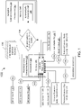
FIG. 1 is a flow diagram of a pilot-monitoring safety system, in accordance with one or more embodiments of the present invention. -
FIG. 2 is a conceptual image of a head worn display, in accordance with one or more embodiments of the present invention. -
FIG. 3 is a graph showing heart rate data collected under increasingly challenging flight conditions, in accordance with one or more embodiments of the present invention. -
FIG. 4 is a plot showing eye gaze data and associated heat maps collected under increasingly challenging flight conditions, in accordance with one or more embodiments of the present invention. - Before explaining at least one embodiment of the inventive concepts disclosed herein in detail, it is to be understood that the inventive concepts are not limited in their application to the details of construction and the arrangement of the components or steps or methodologies set forth in the following description or illustrated in the drawings. In the following detailed description of embodiments of the present disclosure, numerous specific details are set forth in order to provide a more thorough understanding of the inventive concepts. However, it will be apparent to one of ordinary skill in the art having the benefit of the present disclosure that the inventive concepts disclosed herein may be practiced without these specific details. In other instances, well-known features may not be described in detail to avoid unnecessarily complicating the present disclosure. The inventive concepts disclosed herein are capable of other embodiments or of being practiced or carried out in various ways. Also, it is to be understood that the phraseology and terminology employed herein is for the purpose of description and should not be regarded as limiting.
- As used herein a letter following a reference numeral is intended to reference an embodiment of the feature or element that may be similar, but not necessarily identical, to a previously described element or feature bearing the same reference numeral (e.g., 1, 1a, 1b). Such shorthand notations are used for purposes of convenience only, and should not be construed to limit the inventive concepts disclosed herein in any way unless expressly stated to the contrary. Further, unless expressly stated to the contrary, "or" refers to an inclusive or and not to an exclusive or. For example, a condition A or B is satisfied by any one of the following: A is true (or present) and B is false (or not present), A is false (or not present) and B is true (or present), and both A and B are true (or present). In addition, use of the "a" or "an" are employed to describe elements and components of embodiments of the present inventive concepts. This is done merely for convenience and to give a general sense of the inventive concepts, and "a" and "an" are intended to include one or at least one and the singular also includes the plural unless it is obvious that it is meant otherwise.
- Finally, as used herein any reference to "one embodiment" or "some embodiments" means that a particular element, feature, structure, or characteristic described in connection with the embodiment is included in at least one embodiment of the inventive concepts disclosed herein. The appearances of the phrase "in some embodiments" in various places in the specification are not necessarily all referring to the same embodiment, and embodiments of the inventive concepts disclosed may include one or more of the features expressly described or inherently present herein, or any combination or sub-combination of two or more such features, along with any other features which may not necessarily be expressly described or inherently present in the present disclosure.
- As head worn displays proliferate in the aviation industry (e.g., for pilots), features aimed at supporting semi-autonomous single pilot operations are increasingly desirable. When an Air-Transport Category Aircraft (e.g., carrying passengers or cargo) operates with a single crew, it is of critical importance to determine the health, awareness and mental state of the crew for a continuous and safe flight. Many possible solutions exist to monitor pilot health and engagement in the cockpit. However, most solutions are bulky, expensive, complex, or subject to insurmountable certification hurdles. Yet, a high design assurance level (DAL) is critical for pilot-monitoring, since without a high DAL, safety is compromised with potentially catastrophic consequences.
- Embodiments of the present disclosure advantageously combine simple, low-cost biometric sensors with a supervisory logic system that compares and combines the output of each sensor to determine a health state of the pilot (e.g., to detect whether the pilot is alert and capable of piloting the aircraft). The redundant and independent configuration of the sensors may aid in the certification of a high-criticality autopilot system that assumes control of the aircraft in response to a determination that the pilot is unresponsive. The present disclosure differs from other solutions due to low cost, simplicity, and reliability, which are key aspects in manufacturing avionics systems at a high volume.
- Referring now to
FIG. 1 , a flow diagram of a pilot-monitoring safety system 100 is shown in accordance with one or more embodiments of the present disclosure. The pilot-monitoring safety system 100 may include at least a pilot-monitoring computing device 102 and anautopilot computing device 140. In some embodiments, thecomputing devices computing devices more processors memory - Referring now to
FIG. 2 , a conceptual image of a user 200 (e.g., pilot) of the pilot-monitoring safety system 100 is shown. The pilot-monitoring safety system 100 may include a headworn display 210. The headworn display 210 may be, for example, a visor, however the present disclosure is not limited thereto. For example, the headworn display 210 may comprise goggles, glasses, a helmet, etc. In some embodiments, the headworn display 210 is a virtual reality (VR), augmented reality (AR), or mixed reality (MR) system. The headworn display 210 may include an opaque, transparent, or semitransparent display. In some embodiments, the pilot-monitoring computing device 102 may be on-board or embodied in the head worn display 210 (e.g., part of the same mainboard or motherboard, and/or part of the same housing). - Referring back to
FIG. 1 , the pilot-monitoring safety system 100 may include one or more heart rate sensors (e.g., heart rate monitors). For example, thesystem 100 may include aheart rate sensor 110, aheart rate sensor 114, and aheart rate sensor 118. Theheart rate sensors - The
heart rate sensors user 200 of the headworn display 210. For example, theheart rate sensor 110 may be configured to generate primary heart rate measurements, theheart rate sensor 114 may be configured to generate secondary heart rate measurements, and theheart rate sensor 118 may be configured to generate tertiary heart rate measurements. In this way, each of theheart rate sensors system 100. In the case of a failure of one of the heart rate sensors (for example, by generating inaccurate measurements, or no measurements at all), the others of the heart rate sensors may still generate accurate measurements. - In some embodiments, the one or more
heart rate sensors worn display 210. For example, referring again toFIG. 2 , theheart rate sensors temple portion 215 of the head worn display 210 (e.g., attached at an inner side of the headworn display 210 such that the heart rate sensors are adjacent to the skin of the pilot 200). Situating theheart rate sensors pilot 200 may increase the accuracy of the heart rate measurements. Additionally, incorporating theheart rate sensors display 210 as a cohesive package reduces complexity by avoiding the use of chest straps or wrist straps, which are cumbersome and unrealistic for thepilot 200 to wear during flight. Additional heart rate or other biometric sensors may be attached to one or more surfaces of the aircraft cockpit. The additional sensors may operate symbiotically with sensors attached to the head worndisplay 210 for increased reliability. - The pilot-
monitoring safety system 100 may include one or more bloodoxygen saturation sensors 120 and 122 (e.g., pulse oximeters). Theoxygen saturation sensors oxygen saturation sensors sensors user 200. The blood oxygen saturation sensors may be, for example, the WELLUE O2RING, or any sensor including similar fundamental components. - Like the other biometric sensors, the blood
oxygen saturation sensors user 200 of the head worndisplay 210. For example, thesensor 120 may be configured to generate primary blood oxygen saturation measurements, and thesensor 122 may be configured to generate secondary blood oxygen saturation measurements. In this way, each of thesensors heart rate sensors oxygen saturation sensors temple portion 215 of the head worn display 210). - The pilot-
monitoring safety system 100 may include one or more body-pose cameras configured to generate body-pose measurements of thepilot 200. For example, the body-pose cameras may include a laser imaging, detection, and ranging (LIDAR)sensor 124 and a near infrared (NIR) or long-wave infrared (LWIR)sensor 128. TheLIDAR sensor 124 may determine ranges (variable distances) by targeting thepilot 200 with a laser and measuring the time for the reflected light to return to the receiver, and construct a depth map of the pilot 200 (e.g., 3D image). The NIR orLWIR sensors 128 may detect infrared wavelengths (i.e., the heat radiating from the body of the user 200). - The
LIDAR sensor 124 andIR sensor 128 may each measure the body-pose of thepilot 200 from the front or side of thepilot 200, and may detect a static pose from the pilot 200 (i.e., lack of movement), or a slumped body pose, or a tilted neck, of thepilot 200. TheLIDAR sensor 124 may be, for example, an INTEL REALSENSE depth camera, or any sensor including similar fundamental components. TheLIDAR sensor 124 andIR sensor 128 may each be secured, attached, or affixed to one or more surfaces of the cockpit of the aircraft (external to thepilot 200 and the head worn display 210). TheLIDAR sensor 124 andIR sensor 128 may be independently mounted on the surfaces of the cockpit, or may be part of a sensor package that includes other biometric sensors disclosed herein. - The pilot-
monitoring safety system 100 may include one ormore temperature sensors 127 configured to generate temperature measurements of theuser 200 of the head worndisplay 210. Thetemperature sensor 127 may comprise a skin temperature thermometer, for example, the TEMPTRAQ wireless temperature monitor, MAXIM INTEGRATED digital thermometer, or any sensor including similar fundamental components. - The pilot-
monitoring safety system 100 may include one ormore eye trackers display 210. The one ormore eye trackers pilot 200, and thus track movement of the eyes over time. The eye trackers 126, 132, and 134 may comprise a complementary metal oxide semiconductor (CMOS) sensor, a charge-coupled device (CCD) sensor, etc. The eye trackers 126, 132, and 134 may be configured to detect visible light, infrared, ultraviolet, or a combination (e.g., multispectral fusion sensors). The eye trackers 132 and 134 may be, for example, aTOBII PRO 2 eye tracker, or any eye tracker including similar fundamental components or including similar functionality. - The
eye tracker 126 may be placed externally from thepilot 200 and the head worn display 210 (e.g., attached, affixed, or secured, to one or more surfaces of the cockpit of the aircraft). On the other hand, theeye trackers display 210. For example, referring again toFIG. 2 , theeye trackers rim portion 220 of the head worn display 210 (e.g., attached at an inner side of the head worndisplay 210 so that the eye trackers are adjacent and in front of the eyes of the pilot 200). The physical separation of the eye tracker 126 (attached to a surface of the cockpit) from theeye trackers 132 and 134 (attached to the head worn display 210) may provide redundant eye-gaze measurements, and thus may increase the resilience and DAL of thesystem 100. - The pilot-
monitoring safety system 100 may include one or morehead position trackers 130 configured to generate head positions measurements of theuser 200 of the head worndisplay 210. Thehead position tracker 130 may measure the user's head motion using a combination of accelerometer(s), gyroscope(s), magnetometer(s), global positioning system (GPS) sensors, altimeters, etc. Thehead position tracker 130 may generate measurements based on the translation and rotation of the user (e.g., in six degrees of freedom). In some embodiments, thehead position tracker 130 may be one or more inertial measurement units (IMUs). In other embodiments, thehead position tracker 130 may comprise one or more IR trackers or cameras near the user. In general, thehead position tracker 130 may be any device that measures the orientation and position of the head of the user of theHWD 210 over time. - It is noted that the
sensors monitoring computing device 102 using a wired or wireless connection. In some embodiments, the sensors are wirelessly connected using a WiFi or Bluetooth connection. In some embodiments, the sensors are connected by wire to the pilotmonitoring computing device 102 to reduce latency (for example, if thecomputing device 102 is part of the head worn display 210). - The measurements generated by the
sensors statistical database 136. Thedatabase 136 may collect data from a plurality of users of the system 100 (e.g., a population of hundreds or thousands of pilots over a long period of time). The data stored in thedatabase 136 may be used to determine a correlation of each separate measurement (heart rate, eye gaze, body pose, temperature, head position) with others of the measurements with respect to a health state of thepilot 200. The health state may be quantitative (e.g., a numerical value) and/or qualitative (e.g., "pilot under stressful conditions," "pilot partially incapacitated," "pilot fully incapacitated"). -
FIG. 3 is agraph 300 showing heart rate measurement data collected from a pilot under increasingly challenging conditions of a flight simulation, in accordance with one or more embodiments of the present disclosure. The horizontal axis represents time (seconds) and the vertical axis represents heart rate (beats per minute). Theline 310 represents data collected under the advanced difficulty setting, theline 320 represents data collected under the intermediate difficulty setting, and theline 330 represents data collected under the easy difficulty setting. Predictably, the advanced difficulty setting resulted in the highest average heart rate of the user over the simulation (line 310), while the easy difficulty setting resulted in the lowest average heart rate of the user (line 330). -
FIG. 4 showsplots 400 of eye-gaze measurement data collected under the increasingly challenging flight conditions of the simulation described with respect toFIG. 3 , andheat maps 500 associated with theplots 400. Theplots 400 represent the movement of the user's eyes to different instruments, gauges, and displays of an aircraft cockpit. Theplot 410 and associatedheat map 510 represent data collected under the easy difficulty setting, theplot 420 and associatedheat map 520 represent data collected under the intermediate difficulty setting, and theplot 430 and associatedheat map 530 represent data collected under the advanced difficulty setting. Predictably, the advanced difficulty setting resulted in the greatest dispersion of the eye gaze (plot 430 and heat map 530), while the easy difficulty setting resulted in the least dispersion of the eye gaze (plot 410 and heat map 530). -
FIGS. 3 and 4 illustrate the concept of correlating different biometric sensor traces to construct a health state of a pilot of an aircraft. Low stress flight simulator conditions (e.g., the easy difficulty setting with a reduced workload) result in lower heart rates and less dispersion of eye gaze, while relatively high stress flight simulator conditions result in higher heart rates and more dispersion of eye gaze. Collecting data from hundreds or thousands of users of the system 100 (where each user's state is measured by a variety of biometric sensors) may produce a robust model to determine the health state of the user. Data collected from pilot populations over time (such as the data presented inFIGS. 3-4 ) may be classified against pilot performance in general, or against specific pilot tasks (takeoff, hazard avoidance, landing, for example), and stored in thedatabase 136. The data collected from pilot populations over time may then be compared to the metrics collected in real-time by the sensors and head and eye trackers described herein. - Referring back to
FIG. 1 , after generating measurements (heart rate, eye gaze, body pose, temperature, and/or head position) using thesensors user 200 may be determined. The health state of theuser 200 may be quantitative (e.g., a numerical value calculated based on numerical measurement values such as beats per minute, blood oxygen saturation, etc.), and/or qualitative (e.g., "pilot under stressful conditions," "pilot partially incapacitated," "pilot fully incapacitated"). - For example, each of the measurements (heart rate, eye gaze, body pose, temperature, and/or head position) may be normalized (such that each measurement value ranges from 0 to 1, e.g., 0.0, 0.3, 0.7, 1.0, etc.). In some embodiments, each type of measurement may be averaged (for example, the heart rate measurements collected by the
sensors - Additionally or alternatively, qualitative labels may be assigned to each measurement value based on passed thresholds. For example, if the user exceeds an average measured heart rate of 150 bpm (e.g., normalized to 0.75), the contribution of the heart rate measurements to the health state may be labeled as "user under stressful conditions." Alternatively, if the user has an averaged measured heart rate below 15 bpm, or even 0 bpm (e.g., no heart beat or flatline), the contribution of the heart rate measurements to the health state may be labeled "user partially incapacitated" or "user fully incapacitated." The qualitative labels may indicate a dangerous condition of the user 200 (which may require the engagement of the
autopilot computing device 140 to land the aircraft to avoid catastrophe). If all of the different measurements indicate a particular dangerous condition, then the health state of theuser 200 may be associated with the particular dangerous condition. - In some embodiments, the contribution of the measurements (heart rate, eye gaze, body pose, temperature, and/or head position) to the determination of the health state of the
user 200 may be weighted based on a-priori knowledge. In some embodiments, the measurements from the different sensors may be assigned a weight (relative value) based on data stored in the historical orstatistical database 136, and thesystem 100 may employ weighted voting. For example, if the measurements fromheart rate sensor 110 agree (i.e., correlate closely) with the measurements fromheart rate sensor 114, but not with the measurements from theheart rate sensor 118, the measurements fromheart rate sensor 118 may be excluded from contributing to the determination of the health state of the user. Alternatively, the measurements from theheart rate sensor 118 may be given a lower weight (lower reliability) and thus lower contribution to the determination of the health state of the user. - If the health state of the
user 200 indicates a dangerous condition, then a visual alert may be presented to theuser 200 using the head worndisplay 210. A user may then respond to the alert, for example, using a user input device (mouse, keyboard, touchscreen, etc.). Alternatively and/or additionally, the alert may be audial and output from a headset or speakers to theuser 200, and theuser 200 may respond to the alert using a microphone. Alternatively and/or additionally, the alert may be haptic and generated by a vibrating mechanical device (e.g., an eccentric rotating mass [ERM] actuator, a linear resonant actuator [LRA], or a piezoelectric actuator) incorporated into the head mounteddisplay 210, or other surfaces in contact with the pilot's body, such as the seat or the yoke. Theuser 200 may dismiss the alert in the case of a false positive (i.e., theuser 200 being safe and alert), or based on the judgment of theuser 200. However, if theuser 200 does not respond 138 to the alert after a set amount of time has elapsed (e.g., 30 seconds), the pilotmonitoring computing device 102 may transmit a signal to theautopilot computing device 140 to automatically control the aircraft. For example, theautopilot computing device 140 may be communicatively coupled to a flight management system (FMS) and one or more flight control surfaces (ailerons, rudders, elevators, spoilers, flaps, etc.). Theautopilot computing device 140 may guide the aircraft to land at a nearby runway (or on a flat plain, or open ocean), thus avoiding catastrophic consequences in the event that theuser 200 is impaired. - It is believed that the present disclosure and many of its attendant advantages will be understood by the foregoing description, and it will be apparent that various changes may be made in the form, construction, and arrangement of the components without departing from the disclosed subject matter or without sacrificing all of its material advantages. The form described is merely explanatory, and it is the intention of the following claims to encompass and include such changes. Furthermore, it is to be understood that the invention is defined by the appended claims.
Claims (11)
- A pilot-monitoring safety system (100), comprising:a head worn display (210), including:one or more heart rate sensors (110, 114, 118) configured to generate heart rate measurements of a user of the head worn display, wherein the one or more heart rate sensors are attached, secured, or affixed to the head worn display (210); andone or more eye trackers (126, 132, 134) configured to generate eye-gaze measurements of the user of the head worn display, wherein the one or more eye trackers are attached, secured, or affixed to the head worn display;a pilot-monitoring computing device (102) configured to:determine a health state of the user based on at least the heart rate measurements and the eye-gaze measurements; andresponsive to the health state indicating a dangerous condition of the user, present an alert to the user using the head worn display; andan autopilot computing device configured to:
responsive to a predetermined time period elapsing without a response to the alert from the user, automatically control an aircraft. - The system of claim 1, wherein the alert is a visual alert presented on at least one of a display of the head worn display, or a display of a cockpit of the aircraft.
- The system of claim 1 or 2, wherein the alert is an audial alert output by at least one of speakers or headphones.
- The system of any preceding claim, wherein the alert is a haptic alert generated by a vibrating mechanical device secured, attached, or affixed to the head worn display.
- The system of any preceding claim, wherein the heart rate measurements being greater than a heart rate threshold indicates the dangerous condition of the user.
- The system of any preceding claim, wherein the heart rate measurements being less than a heart rate threshold indicates the dangerous condition of the user.
- The system of any preceding claim, further comprising:one or more blood oxygen saturation sensors (120, 122) configured to generate blood oxygen saturation measurements of the user;wherein the determination of the health state of the user is further based on the blood oxygen saturation measurements.
- The system of any preceding claim, further comprising:one or more laser imaging, detection, and ranging, LIDAR, sensors (124) configured to generate body-pose measurements of the user;wherein the one or more LIDAR sensors are secured, attached, or affixed to one or more surfaces of a cockpit of the aircraft;wherein the determination of the health state of the user is further based on the body-pose measurements.
- The system of any preceding claim, further comprising:one or more secondary eye trackers configured to generate secondary eye-gaze measurements of the user;wherein the one or more secondary eye trackers are secured, attached, or affixed to one or more surfaces of a cockpit of the aircraft;wherein the determination of the health state of the user is further based on the secondary eye-gaze measurements of the user.
- The system of any preceding claim, further comprising:one or more head position sensors (130) configured to generate head position measurements of the user;wherein the one or more head position sensors are secured, attached, or affixed to one or more surfaces of a cockpit of the aircraft;wherein the determination of the health state of the user is further based on the head position measurements.
- The system of any preceding claim, wherein automatically controlling the aircraft comprises directing the aircraft to land using one or more flight control surfaces of the aircraft.
Applications Claiming Priority (1)
| Application Number | Priority Date | Filing Date | Title |
|---|---|---|---|
| US17/347,067 US20220396370A1 (en) | 2021-06-14 | 2021-06-14 | High design assurance low cost multi-modal pilot safety systems |
Publications (2)
| Publication Number | Publication Date |
|---|---|
| EP4104761A1 true EP4104761A1 (en) | 2022-12-21 |
| EP4104761B1 EP4104761B1 (en) | 2025-01-01 |
Family
ID=82458623
Family Applications (1)
| Application Number | Title | Priority Date | Filing Date |
|---|---|---|---|
| EP22177647.9A Active EP4104761B1 (en) | 2021-06-14 | 2022-06-07 | High design assurance low cost multi-modal pilot safety systems |
Country Status (2)
| Country | Link |
|---|---|
| US (1) | US20220396370A1 (en) |
| EP (1) | EP4104761B1 (en) |
Families Citing this family (1)
| Publication number | Priority date | Publication date | Assignee | Title |
|---|---|---|---|---|
| CN119366885B (en) * | 2024-12-26 | 2025-04-15 | 中国人民解放军空军特色医学中心 | A method for monitoring pilot's physiological state in the air and evaluating flight state |
Citations (3)
| Publication number | Priority date | Publication date | Assignee | Title |
|---|---|---|---|---|
| WO2015052711A1 (en) * | 2013-10-08 | 2015-04-16 | Elbit Systems Ltd. | Method and system for detecting pilot incompetence based on vital signs and head mounted sensors |
| US20160167672A1 (en) * | 2010-05-14 | 2016-06-16 | Wesley W. O. Krueger | Systems and methods for controlling a vehicle or device in response to a measured human response to a provocative environment |
| EP3459857A1 (en) * | 2017-09-22 | 2019-03-27 | Aurora Flight Sciences Corporation | Systems and methods for monitoring pilot health |
Family Cites Families (2)
| Publication number | Priority date | Publication date | Assignee | Title |
|---|---|---|---|---|
| US9102417B1 (en) * | 2010-12-10 | 2015-08-11 | The Boeing Company | Health monitoring system for a vehicle |
| US20210034053A1 (en) * | 2019-07-30 | 2021-02-04 | The Boeing Company | Pilot Health and Alertness Monitoring, Communication and Safeguarding |
-
2021
- 2021-06-14 US US17/347,067 patent/US20220396370A1/en not_active Abandoned
-
2022
- 2022-06-07 EP EP22177647.9A patent/EP4104761B1/en active Active
Patent Citations (3)
| Publication number | Priority date | Publication date | Assignee | Title |
|---|---|---|---|---|
| US20160167672A1 (en) * | 2010-05-14 | 2016-06-16 | Wesley W. O. Krueger | Systems and methods for controlling a vehicle or device in response to a measured human response to a provocative environment |
| WO2015052711A1 (en) * | 2013-10-08 | 2015-04-16 | Elbit Systems Ltd. | Method and system for detecting pilot incompetence based on vital signs and head mounted sensors |
| EP3459857A1 (en) * | 2017-09-22 | 2019-03-27 | Aurora Flight Sciences Corporation | Systems and methods for monitoring pilot health |
Also Published As
| Publication number | Publication date |
|---|---|
| EP4104761B1 (en) | 2025-01-01 |
| US20220396370A1 (en) | 2022-12-15 |
Similar Documents
| Publication | Publication Date | Title |
|---|---|---|
| US12094316B2 (en) | Flight crew fatigue and controlled rest management system | |
| US11341352B2 (en) | Method of assessing a pilot emotional state | |
| EP3055849B1 (en) | Method and system for detecting pilot incompetence based on vital signs and head mounted sensors | |
| CN109528157A (en) | System and method for monitoring pilot's health | |
| JP6247619B2 (en) | Biological information measuring device | |
| US10328852B2 (en) | Systems and methods to provide feedback to pilot/operator by utilizing integration of navigation and physiological monitoring | |
| EP4104761B1 (en) | High design assurance low cost multi-modal pilot safety systems | |
| US11191467B2 (en) | Method and a device for monitoring the capacity of a crew member of an aircraft | |
| US20230309854A1 (en) | Oxygen saturation monitoring system | |
| CA3008331A1 (en) | Aerial vehicle medical management system | |
| US12148230B2 (en) | System and method for non-invasive operator health monitoring | |
| US10772562B2 (en) | Method for monitoring non-invasive arterial oxygen saturation, pulse rate and detection of carboxyhemoglobin | |
| EP4328871A1 (en) | System and method for non-invasive operator health monitoring | |
| US20240407689A1 (en) | Device for Collecting Biometric and Posture Information for Tracking Consciousness of Rotorcraft Pilot | |
| US20240212365A1 (en) | Method and system for pilot support | |
| Lee et al. | Research on HRI Evaluation System and Diver Safety Equipment | |
| Brokaw et al. | Pilot Medical Monitoring: State of the Science Review on Identification of Pilot Incapacitation | |
| Zhao et al. | Real-time fatigue monitoring and early warning system during extended flights: development and validation | |
| WO2026017589A1 (en) | Portable sensor control system for monitoring haemodynamic parameters of a human organ |
Legal Events
| Date | Code | Title | Description |
|---|---|---|---|
| PUAI | Public reference made under article 153(3) epc to a published international application that has entered the european phase |
Free format text: ORIGINAL CODE: 0009012 |
|
| STAA | Information on the status of an ep patent application or granted ep patent |
Free format text: STATUS: THE APPLICATION HAS BEEN PUBLISHED |
|
| AK | Designated contracting states |
Kind code of ref document: A1 Designated state(s): AL AT BE BG CH CY CZ DE DK EE ES FI FR GB GR HR HU IE IS IT LI LT LU LV MC MK MT NL NO PL PT RO RS SE SI SK SM TR |
|
| STAA | Information on the status of an ep patent application or granted ep patent |
Free format text: STATUS: REQUEST FOR EXAMINATION WAS MADE |
|
| 17P | Request for examination filed |
Effective date: 20230616 |
|
| RBV | Designated contracting states (corrected) |
Designated state(s): AL AT BE BG CH CY CZ DE DK EE ES FI FR GB GR HR HU IE IS IT LI LT LU LV MC MK MT NL NO PL PT RO RS SE SI SK SM TR |
|
| GRAP | Despatch of communication of intention to grant a patent |
Free format text: ORIGINAL CODE: EPIDOSNIGR1 |
|
| STAA | Information on the status of an ep patent application or granted ep patent |
Free format text: STATUS: GRANT OF PATENT IS INTENDED |
|
| INTG | Intention to grant announced |
Effective date: 20240919 |
|
| GRAS | Grant fee paid |
Free format text: ORIGINAL CODE: EPIDOSNIGR3 |
|
| GRAA | (expected) grant |
Free format text: ORIGINAL CODE: 0009210 |
|
| STAA | Information on the status of an ep patent application or granted ep patent |
Free format text: STATUS: THE PATENT HAS BEEN GRANTED |
|
| AK | Designated contracting states |
Kind code of ref document: B1 Designated state(s): AL AT BE BG CH CY CZ DE DK EE ES FI FR GB GR HR HU IE IS IT LI LT LU LV MC MK MT NL NO PL PT RO RS SE SI SK SM TR |
|
| REG | Reference to a national code |
Ref country code: GB Ref legal event code: FG4D |
|
| REG | Reference to a national code |
Ref country code: CH Ref legal event code: EP |
|
| REG | Reference to a national code |
Ref country code: DE Ref legal event code: R096 Ref document number: 602022009249 Country of ref document: DE |
|
| REG | Reference to a national code |
Ref country code: IE Ref legal event code: FG4D |
|
| REG | Reference to a national code |
Ref country code: LT Ref legal event code: MG9D |
|
| REG | Reference to a national code |
Ref country code: NL Ref legal event code: MP Effective date: 20250101 |
|
| REG | Reference to a national code |
Ref country code: AT Ref legal event code: MK05 Ref document number: 1755411 Country of ref document: AT Kind code of ref document: T Effective date: 20250101 |
|
| PG25 | Lapsed in a contracting state [announced via postgrant information from national office to epo] |
Ref country code: NL Free format text: LAPSE BECAUSE OF FAILURE TO SUBMIT A TRANSLATION OF THE DESCRIPTION OR TO PAY THE FEE WITHIN THE PRESCRIBED TIME-LIMIT Effective date: 20250101 |
|
| PG25 | Lapsed in a contracting state [announced via postgrant information from national office to epo] |
Ref country code: FI Free format text: LAPSE BECAUSE OF FAILURE TO SUBMIT A TRANSLATION OF THE DESCRIPTION OR TO PAY THE FEE WITHIN THE PRESCRIBED TIME-LIMIT Effective date: 20250101 |
|
| PG25 | Lapsed in a contracting state [announced via postgrant information from national office to epo] |
Ref country code: PL Free format text: LAPSE BECAUSE OF FAILURE TO SUBMIT A TRANSLATION OF THE DESCRIPTION OR TO PAY THE FEE WITHIN THE PRESCRIBED TIME-LIMIT Effective date: 20250101 |
|
| PGFP | Annual fee paid to national office [announced via postgrant information from national office to epo] |
Ref country code: DE Payment date: 20250520 Year of fee payment: 4 |
|
| PG25 | Lapsed in a contracting state [announced via postgrant information from national office to epo] |
Ref country code: ES Free format text: LAPSE BECAUSE OF FAILURE TO SUBMIT A TRANSLATION OF THE DESCRIPTION OR TO PAY THE FEE WITHIN THE PRESCRIBED TIME-LIMIT Effective date: 20250101 |
|
| PG25 | Lapsed in a contracting state [announced via postgrant information from national office to epo] |
Ref country code: NO Free format text: LAPSE BECAUSE OF FAILURE TO SUBMIT A TRANSLATION OF THE DESCRIPTION OR TO PAY THE FEE WITHIN THE PRESCRIBED TIME-LIMIT Effective date: 20250401 Ref country code: IS Free format text: LAPSE BECAUSE OF FAILURE TO SUBMIT A TRANSLATION OF THE DESCRIPTION OR TO PAY THE FEE WITHIN THE PRESCRIBED TIME-LIMIT Effective date: 20250501 |
|
| PG25 | Lapsed in a contracting state [announced via postgrant information from national office to epo] |
Ref country code: HR Free format text: LAPSE BECAUSE OF FAILURE TO SUBMIT A TRANSLATION OF THE DESCRIPTION OR TO PAY THE FEE WITHIN THE PRESCRIBED TIME-LIMIT Effective date: 20250101 |
|
| PG25 | Lapsed in a contracting state [announced via postgrant information from national office to epo] |
Ref country code: LV Free format text: LAPSE BECAUSE OF FAILURE TO SUBMIT A TRANSLATION OF THE DESCRIPTION OR TO PAY THE FEE WITHIN THE PRESCRIBED TIME-LIMIT Effective date: 20250101 Ref country code: PT Free format text: LAPSE BECAUSE OF FAILURE TO SUBMIT A TRANSLATION OF THE DESCRIPTION OR TO PAY THE FEE WITHIN THE PRESCRIBED TIME-LIMIT Effective date: 20250502 |
|
| PGFP | Annual fee paid to national office [announced via postgrant information from national office to epo] |
Ref country code: FR Payment date: 20250520 Year of fee payment: 4 |
|
| PG25 | Lapsed in a contracting state [announced via postgrant information from national office to epo] |
Ref country code: GR Free format text: LAPSE BECAUSE OF FAILURE TO SUBMIT A TRANSLATION OF THE DESCRIPTION OR TO PAY THE FEE WITHIN THE PRESCRIBED TIME-LIMIT Effective date: 20250402 Ref country code: BG Free format text: LAPSE BECAUSE OF FAILURE TO SUBMIT A TRANSLATION OF THE DESCRIPTION OR TO PAY THE FEE WITHIN THE PRESCRIBED TIME-LIMIT Effective date: 20250101 |
|
| PG25 | Lapsed in a contracting state [announced via postgrant information from national office to epo] |
Ref country code: AT Free format text: LAPSE BECAUSE OF FAILURE TO SUBMIT A TRANSLATION OF THE DESCRIPTION OR TO PAY THE FEE WITHIN THE PRESCRIBED TIME-LIMIT Effective date: 20250101 |
|
| PG25 | Lapsed in a contracting state [announced via postgrant information from national office to epo] |
Ref country code: CZ Free format text: LAPSE BECAUSE OF FAILURE TO SUBMIT A TRANSLATION OF THE DESCRIPTION OR TO PAY THE FEE WITHIN THE PRESCRIBED TIME-LIMIT Effective date: 20250101 |
|
| PG25 | Lapsed in a contracting state [announced via postgrant information from national office to epo] |
Ref country code: SE Free format text: LAPSE BECAUSE OF FAILURE TO SUBMIT A TRANSLATION OF THE DESCRIPTION OR TO PAY THE FEE WITHIN THE PRESCRIBED TIME-LIMIT Effective date: 20250101 |
|
| REG | Reference to a national code |
Ref country code: DE Ref legal event code: R097 Ref document number: 602022009249 Country of ref document: DE |
|
| PG25 | Lapsed in a contracting state [announced via postgrant information from national office to epo] |
Ref country code: SM Free format text: LAPSE BECAUSE OF FAILURE TO SUBMIT A TRANSLATION OF THE DESCRIPTION OR TO PAY THE FEE WITHIN THE PRESCRIBED TIME-LIMIT Effective date: 20250101 |
|
| PG25 | Lapsed in a contracting state [announced via postgrant information from national office to epo] |
Ref country code: DK Free format text: LAPSE BECAUSE OF FAILURE TO SUBMIT A TRANSLATION OF THE DESCRIPTION OR TO PAY THE FEE WITHIN THE PRESCRIBED TIME-LIMIT Effective date: 20250101 |
|
| PG25 | Lapsed in a contracting state [announced via postgrant information from national office to epo] |
Ref country code: IT Free format text: LAPSE BECAUSE OF FAILURE TO SUBMIT A TRANSLATION OF THE DESCRIPTION OR TO PAY THE FEE WITHIN THE PRESCRIBED TIME-LIMIT Effective date: 20250101 |
|
| PG25 | Lapsed in a contracting state [announced via postgrant information from national office to epo] |
Ref country code: EE Free format text: LAPSE BECAUSE OF FAILURE TO SUBMIT A TRANSLATION OF THE DESCRIPTION OR TO PAY THE FEE WITHIN THE PRESCRIBED TIME-LIMIT Effective date: 20250101 |
|
| PG25 | Lapsed in a contracting state [announced via postgrant information from national office to epo] |
Ref country code: RO Free format text: LAPSE BECAUSE OF FAILURE TO SUBMIT A TRANSLATION OF THE DESCRIPTION OR TO PAY THE FEE WITHIN THE PRESCRIBED TIME-LIMIT Effective date: 20250101 |
|
| PG25 | Lapsed in a contracting state [announced via postgrant information from national office to epo] |
Ref country code: SK Free format text: LAPSE BECAUSE OF FAILURE TO SUBMIT A TRANSLATION OF THE DESCRIPTION OR TO PAY THE FEE WITHIN THE PRESCRIBED TIME-LIMIT Effective date: 20250101 |
|
| PLBE | No opposition filed within time limit |
Free format text: ORIGINAL CODE: 0009261 |
|
| STAA | Information on the status of an ep patent application or granted ep patent |
Free format text: STATUS: NO OPPOSITION FILED WITHIN TIME LIMIT |
|
| REG | Reference to a national code |
Ref country code: CH Ref legal event code: L10 Free format text: ST27 STATUS EVENT CODE: U-0-0-L10-L00 (AS PROVIDED BY THE NATIONAL OFFICE) Effective date: 20251112 |
|
| 26N | No opposition filed |
Effective date: 20251002 |
|
| REG | Reference to a national code |
Ref country code: CH Ref legal event code: H13 Free format text: ST27 STATUS EVENT CODE: U-0-0-H10-H13 (AS PROVIDED BY THE NATIONAL OFFICE) Effective date: 20260127 |
|
| PG25 | Lapsed in a contracting state [announced via postgrant information from national office to epo] |
Ref country code: MC Free format text: LAPSE BECAUSE OF FAILURE TO SUBMIT A TRANSLATION OF THE DESCRIPTION OR TO PAY THE FEE WITHIN THE PRESCRIBED TIME-LIMIT Effective date: 20250101 |
|
| PG25 | Lapsed in a contracting state [announced via postgrant information from national office to epo] |
Ref country code: LU Free format text: LAPSE BECAUSE OF NON-PAYMENT OF DUE FEES Effective date: 20250607 |
|
| REG | Reference to a national code |
Ref country code: BE Ref legal event code: MM Effective date: 20250630 |
|
| PG25 | Lapsed in a contracting state [announced via postgrant information from national office to epo] |
Ref country code: IE Free format text: LAPSE BECAUSE OF NON-PAYMENT OF DUE FEES Effective date: 20250607 |
|
| PG25 | Lapsed in a contracting state [announced via postgrant information from national office to epo] |
Ref country code: BE Free format text: LAPSE BECAUSE OF NON-PAYMENT OF DUE FEES Effective date: 20250630 |
|
| PG25 | Lapsed in a contracting state [announced via postgrant information from national office to epo] |
Ref country code: CH Free format text: LAPSE BECAUSE OF NON-PAYMENT OF DUE FEES Effective date: 20250630 |