EP4104747A1 - Grasping mechanism for side-loading optical endoscopes and endoscope camera head with endoscope eyepiece grasping mechanism - Google Patents
Grasping mechanism for side-loading optical endoscopes and endoscope camera head with endoscope eyepiece grasping mechanism Download PDFInfo
- Publication number
- EP4104747A1 EP4104747A1 EP22178997.7A EP22178997A EP4104747A1 EP 4104747 A1 EP4104747 A1 EP 4104747A1 EP 22178997 A EP22178997 A EP 22178997A EP 4104747 A1 EP4104747 A1 EP 4104747A1
- Authority
- EP
- European Patent Office
- Prior art keywords
- rotatable
- eyepiece
- endoscope
- arcuate wall
- base part
- Prior art date
- Legal status (The legal status is an assumption and is not a legal conclusion. Google has not performed a legal analysis and makes no representation as to the accuracy of the status listed.)
- Granted
Links
Images





Classifications
-
- A—HUMAN NECESSITIES
- A61—MEDICAL OR VETERINARY SCIENCE; HYGIENE
- A61B—DIAGNOSIS; SURGERY; IDENTIFICATION
- A61B1/00—Instruments for performing medical examinations of the interior of cavities or tubes of the body by visual or photographical inspection, e.g. endoscopes; Illuminating arrangements therefor
- A61B1/00112—Connection or coupling means
- A61B1/00121—Connectors, fasteners and adapters, e.g. on the endoscope handle
- A61B1/00128—Connectors, fasteners and adapters, e.g. on the endoscope handle mechanical, e.g. for tubes or pipes
-
- A—HUMAN NECESSITIES
- A61—MEDICAL OR VETERINARY SCIENCE; HYGIENE
- A61B—DIAGNOSIS; SURGERY; IDENTIFICATION
- A61B1/00—Instruments for performing medical examinations of the interior of cavities or tubes of the body by visual or photographical inspection, e.g. endoscopes; Illuminating arrangements therefor
- A61B1/00064—Constructional details of the endoscope body
- A61B1/00105—Constructional details of the endoscope body characterised by modular construction
-
- A—HUMAN NECESSITIES
- A61—MEDICAL OR VETERINARY SCIENCE; HYGIENE
- A61B—DIAGNOSIS; SURGERY; IDENTIFICATION
- A61B1/00—Instruments for performing medical examinations of the interior of cavities or tubes of the body by visual or photographical inspection, e.g. endoscopes; Illuminating arrangements therefor
- A61B1/00163—Optical arrangements
- A61B1/00195—Optical arrangements with eyepieces
-
- A—HUMAN NECESSITIES
- A61—MEDICAL OR VETERINARY SCIENCE; HYGIENE
- A61B—DIAGNOSIS; SURGERY; IDENTIFICATION
- A61B1/00—Instruments for performing medical examinations of the interior of cavities or tubes of the body by visual or photographical inspection, e.g. endoscopes; Illuminating arrangements therefor
- A61B1/04—Instruments for performing medical examinations of the interior of cavities or tubes of the body by visual or photographical inspection, e.g. endoscopes; Illuminating arrangements therefor combined with photographic or television appliances
- A61B1/042—Instruments for performing medical examinations of the interior of cavities or tubes of the body by visual or photographical inspection, e.g. endoscopes; Illuminating arrangements therefor combined with photographic or television appliances characterised by a proximal camera, e.g. a CCD camera
-
- A—HUMAN NECESSITIES
- A61—MEDICAL OR VETERINARY SCIENCE; HYGIENE
- A61B—DIAGNOSIS; SURGERY; IDENTIFICATION
- A61B1/00—Instruments for performing medical examinations of the interior of cavities or tubes of the body by visual or photographical inspection, e.g. endoscopes; Illuminating arrangements therefor
- A61B1/04—Instruments for performing medical examinations of the interior of cavities or tubes of the body by visual or photographical inspection, e.g. endoscopes; Illuminating arrangements therefor combined with photographic or television appliances
- A61B1/044—Instruments for performing medical examinations of the interior of cavities or tubes of the body by visual or photographical inspection, e.g. endoscopes; Illuminating arrangements therefor combined with photographic or television appliances for absorption imaging
Definitions
- the present invention relates generally to endoscopic camera devices and more particularly relates to a grasping mechanism or coupler to be fixed on a camera head device or similar optical device to couple the device with an optical endoscope such as a side-loading optical endoscope.
- Endoscopic devices are used in the medical field for observing inside of a patient's body cavity.
- Such endoscopic devices include an insertion unit to be inserted into a patient's body cavity, a light source device that supplies light to the insertion unit that shines onto a target of observation and a removable camera head which is coupled to an eyepiece at the base of the endoscope.
- the camera head may be associated with a control device that controls the camera head as well as a display device that displays images produced by the camera head imaging device such as a CCD, CMOS or similar imaging device.
- Camera heads may be provided with a grasping mechanism or coupler to grasp the eyepiece of an endoscope to effectively couple the endoscope to the camera head.
- the grasping mechanisms typically use multiple parts that require precise machining to provide a twist open and close grasping of the eyepiece. Providing a precision mechanism has entailed high cost with regard to the machining of the multiple parts. Ease-of-use of the grasping mechanism is affected by the structure and the precision of the rotatable parts.
- an endoscope eyepiece grasping mechanism comprising a base part and a rotatable part.
- the base part comprises a base portion with a radially inward light passage and an outer surface and a base part arcuate wall portion disposed radially outward of the light passage.
- the base part arcuate wall portion extends axially from the base portion and extends a circumferential distance between base part arcuate wall portion circumferential ends and defines a base part arcuate wall portion wall opening between the base part arcuate wall portion circumferential ends.
- the rotatable part comprises an annular portion with a radially inward surface, and a rotatable arcuate wall portion including an axial surface extending axially from the annular portion and including a coupling edge with a radial surface extending radially inwardly from the axial surface.
- the rotatable arcuate wall portion extends a circumferential distance between rotatable part arcuate wall portion circumferential ends and defines a rotatable part arcuate wall opening between the rotatable arcuate wall portion circumferential ends.
- a path guide provides guided movement of the rotatable part relative to the base part for moving the rotatable arcuate wall portion relative to the base part between an open state and a closed state.
- the rotatable part arcuate wall opening and the base part arcuate wall portion wall opening at least partially overlap to define a eyepiece receiving spacing and with the radial surface spaced from the base portion by a first axial distance to define an endoscope eyepiece side opening.
- the rotatable part arcuate wall opening and the base part arcuate wall portion wall opening do not overlap or overlap to an extent to provide a gap that is smaller than the endoscope receiving spacing and with the radial surface spaced from the base portion by a second axial distance, which second axial distance is smaller than said first axial distance.
- a biasing device acts to bias the rotatable part toward the closed state.
- An endoscope eyepiece may be pushed through the endoscope eyepiece side opening to a coupled position in the open state.
- the rotatable part rotates to the closed state and the radial surface moves axially toward the base position to retain the eyepiece in the coupled position.
- the path guide may advantageously comprise a helical groove in the outer surface of the base portion, the helical groove extending circumferentially about at least a portion of a base part outer periphery.
- a helical race groove may be provided in the radially inward surface of the rotatable part.
- a ball arrangement may be provided comprising a ball partially disposed in the race groove and partially disposed in the helical groove. The ball, the race groove and the helical groove guide the rotatable part relative to the base part between the open state and the closed state.
- the base part may be an injection molded part with the helical groove formed in the outer surface.
- the rotatable part may be an injection molded part with the race groove formed in the radially inward surface.
- a limit configuration may be provided to limit rotation of the rotatable part relative to the base part in each of two rotational directions.
- the limit configuration advantageously comprises a limit helical groove extending essentially parallel to the helical groove of the rotational part.
- the limit helical groove may have a limited circumferential extent between a first limit end and a second limit end.
- a limit ball is provided in the limit helical groove.
- a limit ball support may support the limit ball relative to the limit helical groove, whereby the movement of rotational part relative to the base part is limited by the travel of the limit ball between the first limit end and the second limit end.
- the helical groove may be in the outer surface of the base portion and extend less than 360 ° about a circumference of the base portion.
- the ball configuration or ball arrangement may comprise a plurality of balls partially disposed in the race groove and partially disposed in the helical groove.
- the grasping mechanism may further comprise a limit configuration limiting rotation of the rotatable part relative to the base part.
- the bias device may comprise one or more compression springs.
- the rotatable part has an eyepiece contact surface at one of the arcuate wall portion circumferential ends.
- the rotatable part arcuate wall opening and the base part arcuate wall portion wall opening overlap to form the gap in the closed state.
- the endoscope eyepiece presses the eyepiece contact surface to rotate the rotatable part towards the open state to allow the endoscope eyepiece to be pushed through the endoscope eyepiece side opening to the coupled position.
- the base part may be connected to a camera head chassis.
- a camera head comprises a camera head chassis and an endoscope eyepiece grasping mechanism having some or all of the features as discussed above.
- the base part is connected to a camera head chassis.
- an endoscope system comprising: an endoscope with an endoscope eyepiece and a camera head having some or all of the features as discussed above.
- the disclosed devices advantageously are formed of molded parts allowing precision helical grooves to be provided that receive stainless steel balls or other similar relatively low-cost friction reducing features to guide the relatively moving parts. Such molded parts can be effectively made to provide a high quality and precision endoscope eyepiece grasping mechanism.
- the endoscope eyepiece grasping mechanism is particularly robust and advantageous as to construction with the two-piece top (rotatable part) and bottom (base part) grasping mechanism.
- the grasping mechanism may be made with low costs, relative to the precision attained, based on injection molded top / bottom with any colors required.
- a single heat staked pin may engage a single limit ball to capture all components. No lubrication is required based on self-lubricating injection molded plastic for both the top and bottom.
- the configuration particularly provides the advantage of a single hand top side snap-in insertion endoscope engagement - no second hand is required for insertion of the endoscope.
- the endoscope may be pressed into the gap in the closed state to rotate the rotatable part (top) at a set spring force using finger / s only.
- the configuration provides a smooth rotation through low friction compression spring coil line contact plus a near frictionless point contact only of stainless steel balls.
- Figure 1A shows a grasping mechanism generally designated 10, which is attached to a mounting portion 12 of a camera head chassis 2.
- the grasping mechanism 10 comprises a base part 20 and a rotatable part 40.
- the rotatable part 40 rotates about the base part 20.
- the base part 20 attaches to the camera chassis 2 in a central region at the mounting portion 12, via a threaded retaining nut or other known fastening mechanism.
- FIG 1A shows the grasping mechanism 10 in a closed state or grasping position.
- an endoscope eyepiece 6 ( Figures 7 - 9 ), disposed in an interior region 14 of the grasping mechanism 10, is in a coupled position and is grasped by the grasping mechanism 10, to couple the endoscope eyepiece 6 to the camera head 2.
- the grasping mechanism 10 partially surrounds a periphery of the endoscope eyepiece 6 that is disposed in the central interior region 14, to prevent radial displacement from the coupled position and also clamps the endoscope eyepiece 6 in an axial direction to prevent axial displacement of the endoscope eyepiece 6 out of the coupled position.
- Figure 1B shows the grasping mechanism 10 in an open state or loading position.
- the endoscope eyepiece 6 may be inserted into the interior region 14 of the grasping mechanism 10 by passing the eyepiece 6 through a base part arcuate wall portion wall opening 30 and through a rotatable part arcuate wall opening 50, which openings overlap, at least to some degree, in this open state.
- the endoscope eyepiece 6 is moved laterally into the interior region 14 of the grasping mechanism 10 to the coupled position ( Figure 7 ).
- the grasping mechanism 10 is then actuated, namely allowed to transition from the open state shown in Figure 1B to the closed state shown in Figure 1A under the action of a biasing force.
- the insertion is accomplished with a snap in action with no need to rotate the rotatable part 40 by hand.
- Figures 3A and 3B show the base part 20 detached from the rest of the grasping mechanism 10.
- the base part 20 defines a lower portion of the interior region 14 which forms the space for the endoscope eyepiece 6, when the endoscope eyepiece 6 is in the coupled (closed) position.
- the interior region 14 is delimited by a contoured surface 16, that surrounds and defines a radially inward light passage opening 18, and by an inner surface 28 of a base part arcuate wall 24.
- the arcuate wall 24 is radially outward of the light passage 18 and extends upwardly from a base portion 22 of the base part 20.
- the base part arcuate wall 24 extends a circumferential distance between a base part arcuate wall portion first circumferential end 25 and a second circumferential end 26.
- the arcuate wall circumferential ends 25 and 26 define the base part arcuate wall portion wall opening 30.
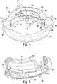
- Figure 4 shows the rotatable part 40 including a lower annular portion 42 that has a radially inward surface 43.
- the rotatable part 40 further has a rotatable arcuate wall portion 44 that is a continuation of the radially inward surface 43 and that extends axially from the annular portion 42, in an upward direction, as shown in Figure 4 .
- a radial surface 47 extends radially inwardly from the radially inward surface 43 to an edge 46.
- the rotatable arcuate wall portion 44 has a circumferential extent between a rotatable part arcuate wall portion first end 48 and a rotatable part arcuate wall portion second end 49.
- a first grasping flange 54 is provided at the arcuate wall portion first end 48 and a second grasping flange 55 is provided at the arcuate wall portion second end 48.
- the grasping mechanism 10 includes a path guide comprising a helical race groove 64 that is provided by the rotatable part 40 ( Figure 4 ).
- the path guide also includes a helical groove 62 provided by the base part 20 ( Figures 3A and 3B ) and a ball arrangement or ball configuration 60 with balls 66 and biasing device 70.
- the helical groove 62 and the helical race groove 64 together form a split helical groove space or cavity that receives the ball arrangement 60.
- the path guide acts between the base part 20, and the rotatable part 40 for guided movement of the rotatable part 40 relative to the base part 20 for moving the rotatable arcuate wall portion 44 of the rotatable part 40 relative to the base part 20 between the closed state and the open state.
- FIG. 1B in the open state, the rotatable part arcuate wall opening 50 and the base part arcuate wall portion wall opening 30 extensively overlap.
- the path guide acts to change an axial spacing between portions of the rotatable part 40 and the base part 20.
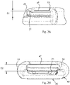
- a first axial distance D1 and a second axial distance D2 are shown measured from a surface 21 of the base part 20 to the radial surface 47.
- the first axial distance D1 ( Figures 1A , 2A ) is smaller than the second axial distance D2 ( Figures 2A and 2B ).
- the radial surface 47 of the rotatable part 40 is spaced from the surface 21 of the base portion 22 by the first axial distance D1 ( Figure 2A ).
- the radial surface 47 of the rotatable part 40 is spaced from a surface 21 of the base portion 22 by the second axial distance D2 ( Figure 2B ).
- the first axial distance D1 such as 4.84 mm, is coordinated with the dimensions and shape of the endoscope eyepiece 6 so as to clamp and hold the endoscope eyepiece 6 in the inner space 18, between the radial surface 47 of the rotatable part 40 and the contoured surface 16 of the base part 20, with the grasping mechanism 10 in the closed state.
- the second axial distance D2 is sufficient to allow the endoscope eyepiece 6 to be inserted into and removed from the inner space 18, based on sufficient space being provided between the surface 21 and the radial surface 47 to accommodate the passage of the endoscope eyepiece 6 through the overlapping wall openings 30 and 50.
- This second axial distance D2 is coordinated with the shape of the endoscope eyepiece 6.
- the grasping mechanism 10 grasps the endoscope eyepiece 6 to fully retain and hold the endoscope eyepiece 6 from movement relative to the grasping mechanism 10 and the camera head chassis 2.
- the grasping mechanism 10 includes the biasing device 70 that biases the rotatable part for relative movement toward the closed state.
- biasing device 70 is integrated into the ball arrangement 60.
- the biasing device 70 advantageously comprises one or more compression springs 75.
- the compression spring 75 are mounted in the helical groove 62 and race groove 64, and act between balls 66.
- a trailing ball 65 of the ball arrangement 60 interacts with a race groove end 69, as an engagement point with the rotatable part 40, and a leading ball 67 of the ball arrangement 60 interacts with a helical groove end 27, as an engagement point with the base part 20.
- the compression springs 75 of the biasing device 70 With the grasping mechanism 10 in the closed state, the compression springs 75 of the biasing device 70, between a leading ball 67 and a trailing ball 65 of the ball arrangement 60, are in a non-compressed or less compressed state.
- the leading ball 67 ( Figure 6A ) of the ball arrangement 60 With the grasping mechanism 10 in the open state the leading ball 67 ( Figure 6A ) of the ball arrangement 60 is positioned at the helical groove end 27 ( Figure 3A ) of the base part 20 and the trailing ball 65 is positioned at race groove end 69 of the rotatable part 40 ( Figure 5 ).
- these ends 27 and 69 are circumferentially closer to each other than in the closed state, such that the compression springs 75 of the biasing device 70 are more compressed.
- the compressed springs 75 apply a rotational force to rotate the rotatable part 40 clockwise from the open state shown in Figure 1B to the closed state shown in Figure 1A .
- the helical groove 62 is formed in the outer surface 23 of the base portion 22 of the base part 20.
- the helical groove 62 extends circumferentially about at least a portion of the base part outer periphery. Although the groove 62 is described as helical or spiral, the groove 62 need not extend fully around the outer periphery of the base portion 22. In the disclosed embodiments the helical groove 62 extends approximately 270 ° about the circumference of the peripheral surface 23.
- the race groove 64 is formed in the radially inward surface 43 of the rotatable part 40, particularly at an inner surface of the arcuate wall portion 44.
- the ball configuration 66 comprises two or more balls 66, preferably a plurality of steel balls 66 in addition to the trailing ball 65 and the leading ball 67.
- the balls 66 are partially disposed in the race groove 64 and are partially disposed in the helical groove 62.
- the biasing device 70 advantageously comprises stainless steel compression springs 75 of approximately 38 mm length and 3 mm outer diameter.
- the balls 65, 66, 67 advantageously comprise approximately thirteen 3 mm stainless steel balls with a configuration as shown in Figure 6A .
- the base member 20 is placed within the rotatable member 40 and rotated to a position in which a limit ball access passage 90, formed in the base member 20, is aligned with a loading position marker 96 ( Figures 6A and 6B ).
- the base member 20 is next rotated to a position in which a limit ball access passage 90 is aligned with a use position marker 94 ( Figure 6B ).
- the limit ball 86 is next put into the limit ball access passage 90 and a limit ball access closure 92 is pushed into the limit ball access passage 90.
- This has a limit ball support 93 that supports the limit ball 86 such that the limit ball 86 is partially in a limit ball space 88 ( Figure 3A ) of the base part 20 and extends out of the space 88 into a limit helical groove 82 of the rotatable part 40 ( Figure 4 ).
- the limit ball access closure 92 is fixed in place by a heat staking to capture the non-removable pin or limit ball support 93, that positions and retains single limiter ball, in the groove 82 and capture all components.
- a limit configuration that limits the rotation of the rotatable part 40 relative to the base part 20, is formed by the limit helical groove 82 which extends essentially parallel to the helical groove 62 along a limited extent of the inner surface 43 of the rotatable part 40.
- the limited extent of the limit helical groove 82 is defined by a first limit end 81 and a second limit end 83 ( Figure 4 ).
- the limit ball 86, disposed partially in the limit ball space 88 and partially in the helical groove 82 is limited to move along the helical groove 82 between the first limit end 81 and the second limit end 83.
- the limit configuration further includes the limit ball support 93 and the base part that defines the space 88 so as to support the limit ball 86 and hold the limit ball 86 in the location relative to the base part 20.
- Figure 7 shows the camera head 2 with the endoscope eyepiece grasping mechanism 10 along with a positioned endoscope 4.
- the endoscope 4 has the endoscope eyepiece 6.
- Figure 7 also shows a light source connection 7 as well as a signal connection line 8 that is connected to the camera head 2.
- the rotatable part 40 advantageously includes the first grasping flange 54 coordinated with the rotatable part arcuate wall portion end 48 and the second grasping flange 55 coordinated with the rotatable part arcuate wall portion end 49.
- This facilitates the ability to actuate the grasping device 10.
- the user can engage either flange, such as the flange 55, to rotate the rotatable part 40 in the counterclockwise direction to open the grasping mechanism 10 so the endoscope eyepiece 6 may slide in from the side, through the openings 30 and 50 to the interior region 14 of the grasping member 10.
- a side loading direction SL of the endoscope eyepiece 6 is shown in Figure 7 .
- the biasing device 70 acts on the rotatable part 40 relative to the base part 20, to rotate the rotatable part 40 back to the closed state as shown in Figure 1A so as to capture the endoscope eyepiece 6 and retain the endoscope eyepiece 6 under compression spring force with the radial inner surface 47 acting axially towards the base part 20 to retain the endoscope eyepiece 6 in the coupled position.
- An aspect of the disclosed embodiment is the configuration which presents a gap G between portions of the axial walls 24 and 44 in the closed state ( Figure 1A ), namely the gap G is between the axial wall end 25 of axial wall 24 and the end 49 of rotatable wall portion 44 in the closed state.
- This gap G and the eyepiece contact surface of the flange 55, at the end 49, are such that the user may simply press the endoscope eyepiece 6 in the region the gap G, particularly pressing the endoscope eyepiece 6 against the flange 55 and wall end 25.
- Each of the base part 20 and the rotatable part 40 is preferably formed as a molded part such as an injection molded part made of plastic material such as PEEK + 20% PTFE. After injection molding, further machining can be provided. However, advantageously the molded parts are fully formed by the injection molding process and are formed so as to be ready to be assembled.
- balls 65, 66, 67 steel balls
- these may be replaced with another friction reducing material or a member with added seals or other related features.
- biasing devices may be provided instead of the compression spring arrangement with compression springs 75.
- a coil spring may act between the base part 20 and the rotatable part 40.
- other limiter configurations may be provided.
- An endoscope eyepiece grasping mechanism includes a base part with an arcuate wall portion defining a base part wall opening between the base part arcuate wall portion circumferential ends and a rotatable part with a rotatable arcuate wall portion defining a rotatable part arcuate wall opening between the rotatable arcuate wall portion circumferential ends.
- a path guide rotates and axially moves the rotatable part relative to the base part between an open and closes state.
- a biasing device acts to bias the rotatable part toward the closed state, whereby an endoscope eyepiece may be pushed through an endoscope eyepiece side opening to a coupled position in the open state and the rotatable part rotates to the closed state and moves axially toward the base to retain the eyepiece in the coupled position.
Landscapes
- Health & Medical Sciences (AREA)
- Life Sciences & Earth Sciences (AREA)
- Surgery (AREA)
- Engineering & Computer Science (AREA)
- Biomedical Technology (AREA)
- Heart & Thoracic Surgery (AREA)
- Pathology (AREA)
- Radiology & Medical Imaging (AREA)
- Nuclear Medicine, Radiotherapy & Molecular Imaging (AREA)
- Biophysics (AREA)
- Physics & Mathematics (AREA)
- Optics & Photonics (AREA)
- Medical Informatics (AREA)
- Molecular Biology (AREA)
- Animal Behavior & Ethology (AREA)
- General Health & Medical Sciences (AREA)
- Public Health (AREA)
- Veterinary Medicine (AREA)
- Mechanical Engineering (AREA)
- Endoscopes (AREA)
Abstract
Description
- The present invention relates generally to endoscopic camera devices and more particularly relates to a grasping mechanism or coupler to be fixed on a camera head device or similar optical device to couple the device with an optical endoscope such as a side-loading optical endoscope.
- Endoscopic devices are used in the medical field for observing inside of a patient's body cavity. Such endoscopic devices include an insertion unit to be inserted into a patient's body cavity, a light source device that supplies light to the insertion unit that shines onto a target of observation and a removable camera head which is coupled to an eyepiece at the base of the endoscope. The camera head may be associated with a control device that controls the camera head as well as a display device that displays images produced by the camera head imaging device such as a CCD, CMOS or similar imaging device.
- Camera heads may be provided with a grasping mechanism or coupler to grasp the eyepiece of an endoscope to effectively couple the endoscope to the camera head. The grasping mechanisms typically use multiple parts that require precise machining to provide a twist open and close grasping of the eyepiece. Providing a precision mechanism has entailed high cost with regard to the machining of the multiple parts. Ease-of-use of the grasping mechanism is affected by the structure and the precision of the rotatable parts.
- It is an object of the invention to provide an endoscope eyepiece grasping mechanism which can be provided with a camera head and which can grasp an eyepiece of an endoscope to couple the endoscope to the camera head with a reliable configuration that provides a precision grasping of the eyepiece while avoiding the high costs of precision machining.
- It is a further object of the invention to provide a dependable endoscope eyepiece grasping mechanism which is easy to actuate and preferably can be single hand actuated.
- According to the invention, an endoscope eyepiece grasping mechanism is provided comprising a base part and a rotatable part. The base part comprises a base portion with a radially inward light passage and an outer surface and a base part arcuate wall portion disposed radially outward of the light passage. The base part arcuate wall portion extends axially from the base portion and extends a circumferential distance between base part arcuate wall portion circumferential ends and defines a base part arcuate wall portion wall opening between the base part arcuate wall portion circumferential ends. The rotatable part comprises an annular portion with a radially inward surface, and a rotatable arcuate wall portion including an axial surface extending axially from the annular portion and including a coupling edge with a radial surface extending radially inwardly from the axial surface. The rotatable arcuate wall portion extends a circumferential distance between rotatable part arcuate wall portion circumferential ends and defines a rotatable part arcuate wall opening between the rotatable arcuate wall portion circumferential ends. A path guide provides guided movement of the rotatable part relative to the base part for moving the rotatable arcuate wall portion relative to the base part between an open state and a closed state. In the open state the rotatable part arcuate wall opening and the base part arcuate wall portion wall opening at least partially overlap to define a eyepiece receiving spacing and with the radial surface spaced from the base portion by a first axial distance to define an endoscope eyepiece side opening. In the closed state the rotatable part arcuate wall opening and the base part arcuate wall portion wall opening do not overlap or overlap to an extent to provide a gap that is smaller than the endoscope receiving spacing and with the radial surface spaced from the base portion by a second axial distance, which second axial distance is smaller than said first axial distance. A biasing device acts to bias the rotatable part toward the closed state. An endoscope eyepiece may be pushed through the endoscope eyepiece side opening to a coupled position in the open state. The rotatable part rotates to the closed state and the radial surface moves axially toward the base position to retain the eyepiece in the coupled position.
- The path guide may advantageously comprise a helical groove in the outer surface of the base portion, the helical groove extending circumferentially about at least a portion of a base part outer periphery. A helical race groove may be provided in the radially inward surface of the rotatable part. A ball arrangement may be provided comprising a ball partially disposed in the race groove and partially disposed in the helical groove. The ball, the race groove and the helical groove guide the rotatable part relative to the base part between the open state and the closed state.
- The base part may be an injection molded part with the helical groove formed in the outer surface. The rotatable part may be an injection molded part with the race groove formed in the radially inward surface.
- A limit configuration may be provided to limit rotation of the rotatable part relative to the base part in each of two rotational directions. The limit configuration advantageously comprises a limit helical groove extending essentially parallel to the helical groove of the rotational part. The limit helical groove may have a limited circumferential extent between a first limit end and a second limit end. A limit ball is provided in the limit helical groove. A limit ball support may support the limit ball relative to the limit helical groove, whereby the movement of rotational part relative to the base part is limited by the travel of the limit ball between the first limit end and the second limit end.
- The helical groove may be in the outer surface of the base portion and extend less than 360 ° about a circumference of the base portion.
- The ball configuration or ball arrangement may comprise a plurality of balls partially disposed in the race groove and partially disposed in the helical groove.
- The grasping mechanism may further comprise a limit configuration limiting rotation of the rotatable part relative to the base part.
- The bias device may comprise one or more compression springs.
- The rotatable part has an eyepiece contact surface at one of the arcuate wall portion circumferential ends. With this configuration, the rotatable part arcuate wall opening and the base part arcuate wall portion wall opening overlap to form the gap in the closed state. Upon pressing the endoscope eyepiece toward and through the gap the endoscope eyepiece presses the eyepiece contact surface to rotate the rotatable part towards the open state to allow the endoscope eyepiece to be pushed through the endoscope eyepiece side opening to the coupled position.
- The base part may be connected to a camera head chassis.
- According to another aspect of the invention, a camera head comprises a camera head chassis and an endoscope eyepiece grasping mechanism having some or all of the features as discussed above. The base part is connected to a camera head chassis.
- According to another aspect of the invention, an endoscope system is provided comprising: an endoscope with an endoscope eyepiece and a camera head having some or all of the features as discussed above.
- The disclosed devices advantageously are formed of molded parts allowing precision helical grooves to be provided that receive stainless steel balls or other similar relatively low-cost friction reducing features to guide the relatively moving parts. Such molded parts can be effectively made to provide a high quality and precision endoscope eyepiece grasping mechanism.
- The endoscope eyepiece grasping mechanism is particularly robust and advantageous as to construction with the two-piece top (rotatable part) and bottom (base part) grasping mechanism. The grasping mechanism may be made with low costs, relative to the precision attained, based on injection molded top / bottom with any colors required. A single heat staked pin may engage a single limit ball to capture all components. No lubrication is required based on self-lubricating injection molded plastic for both the top and bottom. The configuration particularly provides the advantage of a single hand top side snap-in insertion endoscope engagement - no second hand is required for insertion of the endoscope. In particular the endoscope may be pressed into the gap in the closed state to rotate the rotatable part (top) at a set spring force using finger / s only. The endoscope friction locks with a clockwise finger rotation with a max. open / close rotation of approximately 72 °. The configuration provides a smooth rotation through low friction compression spring coil line contact plus a near frictionless point contact only of stainless steel balls.
- The various features of novelty which characterize the invention are pointed out with particularity in the claims annexed to and forming a part of this disclosure. For a better understanding of the invention, its operating advantages and specific objects attained by its uses, reference is made to the accompanying drawings and descriptive matter in which preferred embodiments of the invention are illustrated. The features of the invention as mentioned above and as described below apply not only in the combinations mentioned but also in other combinations or alone, without leaving the scope of the present invention. Further aspects of the present invention will be apparent from the figures and from the description of particular embodiments that follow. These figures show examples of the invention. The figures, the description and the requirements contain numerous features in combination. One of skill in the art will recognize the features individually and combine them into meaningful further combinations.
- In the drawings:
- Figure 1A
- is a perspective view showing an endoscope eyepiece grasping mechanism in a closed state and with features according to the invention;
- Figure 1B
- is a perspective view showing the endoscope eyepiece grasping mechanism in an open state;
- Figure 2A
- is a side view showing the endoscope eyepiece grasping mechanism of
Figures 1A and1B in the closed state; - Figure 2B
- is a side partially cutaway view showing the endoscope eyepiece grasping mechanism of
Figures 1A and1B in the open state; - Figure 3A
- is a perspective view of a base part of the endoscope eyepiece grasping mechanism of
Figures 1A and1B ; - Figure 3B
- is a perspective view of the base part of
Figure 3A , rotated counterclockwise by about 180 ° relative to the view ofFigure 3A ; - Figure 4
- is a perspective view showing a rotatable part, a ball arrangement (configuration) with balls and a biasing device in a race helical groove, a limit ball, partially in section, in a limit groove, as well as a limit ball support of a limit ball access clo-sure of the endoscope eyepiece grasping mechanism of
Figure 1A and1B ; - Figure 5
- is a perspective partially sectional view showing the rotatable part with some of the ball arrangement (configuration) in the race helical groove;
- Figure 6A
- is a perspective view of a endoscope eyepiece grasping mechanism with the limit ball removed and the base part at a rotational position relative to the rotatable part allowing a loading of the ball arrangement (configuration) and a biasing device into the race groove and showing the ball configuration;
- Figure 6B
- is a perspective view of a endoscope eyepiece grasping mechanism with the base part at a rotational position relative to the rotatable part to allow the shown limit ball to be inserted into the limit ball access passage, which is to be closed by the limit ball access closure shown;
- Figure 7
- is a perspective view showing a snap in action insertion of an endoscope, having an endoscope eyepiece, into the grasping mechanism of a camera head;
- Figure 8
- is a perspective view showing the endoscope having the endoscope eyepiece in-serted in the grasping mechanism of the camera head; and
- Figure 9
- is a perspective view showing an endoscope, having an endoscope eyepiece, being removed from the grasping mechanism of the camera head.
- Referring to the drawings,
Figure 1A shows a grasping mechanism generally designated 10, which is attached to a mountingportion 12 of acamera head chassis 2. The graspingmechanism 10 comprises abase part 20 and arotatable part 40. Therotatable part 40 rotates about thebase part 20. Thebase part 20 attaches to thecamera chassis 2 in a central region at the mountingportion 12, via a threaded retaining nut or other known fastening mechanism. -
Figure 1A shows the graspingmechanism 10 in a closed state or grasping position. In this closed state an endoscope eyepiece 6 (Figures 7 - 9 ), disposed in aninterior region 14 of the graspingmechanism 10, is in a coupled position and is grasped by the graspingmechanism 10, to couple theendoscope eyepiece 6 to thecamera head 2. In this closed state, the graspingmechanism 10 partially surrounds a periphery of theendoscope eyepiece 6 that is disposed in the centralinterior region 14, to prevent radial displacement from the coupled position and also clamps theendoscope eyepiece 6 in an axial direction to prevent axial displacement of theendoscope eyepiece 6 out of the coupled position. -
Figure 1B shows the graspingmechanism 10 in an open state or loading position. In this open state theendoscope eyepiece 6 may be inserted into theinterior region 14 of the graspingmechanism 10 by passing theeyepiece 6 through a base part arcuate wallportion wall opening 30 and through a rotatable part arcuate wall opening 50, which openings overlap, at least to some degree, in this open state. Theendoscope eyepiece 6 is moved laterally into theinterior region 14 of the graspingmechanism 10 to the coupled position (Figure 7 ). The graspingmechanism 10 is then actuated, namely allowed to transition from the open state shown inFigure 1B to the closed state shown inFigure 1A under the action of a biasing force. As shown inFigure 7 , the insertion is accomplished with a snap in action with no need to rotate therotatable part 40 by hand. -
Figures 3A and 3B show thebase part 20 detached from the rest of the graspingmechanism 10. Thebase part 20 defines a lower portion of theinterior region 14 which forms the space for theendoscope eyepiece 6, when theendoscope eyepiece 6 is in the coupled (closed) position. Theinterior region 14 is delimited by a contouredsurface 16, that surrounds and defines a radially inwardlight passage opening 18, and by aninner surface 28 of a base partarcuate wall 24. Thearcuate wall 24 is radially outward of thelight passage 18 and extends upwardly from abase portion 22 of thebase part 20. The base partarcuate wall 24 extends a circumferential distance between a base part arcuate wall portion firstcircumferential end 25 and a secondcircumferential end 26. The arcuate wall circumferential ends 25 and 26 define the base part arcuate wallportion wall opening 30. -
Figure 4 shows therotatable part 40 including a lowerannular portion 42 that has a radiallyinward surface 43. Therotatable part 40 further has a rotatablearcuate wall portion 44 that is a continuation of the radiallyinward surface 43 and that extends axially from theannular portion 42, in an upward direction, as shown inFigure 4 . Aradial surface 47 extends radially inwardly from the radiallyinward surface 43 to anedge 46. The rotatablearcuate wall portion 44 has a circumferential extent between a rotatable part arcuate wall portionfirst end 48 and a rotatable part arcuate wall portionsecond end 49. A first graspingflange 54 is provided at the arcuate wall portionfirst end 48 and a second graspingflange 55 is provided at the arcuate wall portionsecond end 48. - The grasping
mechanism 10 includes a path guide comprising ahelical race groove 64 that is provided by the rotatable part 40 (Figure 4 ). The path guide also includes ahelical groove 62 provided by the base part 20 (Figures 3A and 3B ) and a ball arrangement orball configuration 60 withballs 66 and biasingdevice 70. Thehelical groove 62 and thehelical race groove 64 together form a split helical groove space or cavity that receives theball arrangement 60. The path guide acts between thebase part 20, and therotatable part 40 for guided movement of therotatable part 40 relative to thebase part 20 for moving the rotatablearcuate wall portion 44 of therotatable part 40 relative to thebase part 20 between the closed state and the open state. As can be seen inFigure 1B , in the open state, the rotatable part arcuate wall opening 50 and the base part arcuate wall portion wall opening 30 extensively overlap. In addition the path guide acts to change an axial spacing between portions of therotatable part 40 and thebase part 20. A first axial distance D1 and a second axial distance D2 are shown measured from asurface 21 of thebase part 20 to theradial surface 47. The first axial distance D1 (Figures 1A ,2A ) is smaller than the second axial distance D2 (Figures 2A and 2B ). - In the closed state, the
radial surface 47 of therotatable part 40 is spaced from thesurface 21 of thebase portion 22 by the first axial distance D1 (Figure 2A ). In the open state, theradial surface 47 of therotatable part 40 is spaced from asurface 21 of thebase portion 22 by the second axial distance D2 (Figure 2B ). The first axial distance D1, such as 4.84 mm, is coordinated with the dimensions and shape of theendoscope eyepiece 6 so as to clamp and hold theendoscope eyepiece 6 in theinner space 18, between theradial surface 47 of therotatable part 40 and the contouredsurface 16 of thebase part 20, with the graspingmechanism 10 in the closed state. The second axial distance D2, such as 6.75 mm, is sufficient to allow theendoscope eyepiece 6 to be inserted into and removed from theinner space 18, based on sufficient space being provided between thesurface 21 and theradial surface 47 to accommodate the passage of theendoscope eyepiece 6 through the overlappingwall openings endoscope eyepiece 6. With the graspingmechanism 10 in the closed state, and theendoscope eyepiece 6 in the coupled position, seated in thecontour surface 16 and clamped between the lowerradial surface 47 and the contouredsurface 16, with a peripheral edge of theendoscope eyepiece 6 in contact with theinner surface 28 of theaxial wall 24, the graspingmechanism 10 grasps theendoscope eyepiece 6 to fully retain and hold theendoscope eyepiece 6 from movement relative to the graspingmechanism 10 and thecamera head chassis 2. - The grasping
mechanism 10 includes the biasingdevice 70 that biases the rotatable part for relative movement toward the closed state. In the embodiment shown in the figures, biasingdevice 70 is integrated into theball arrangement 60. According to the embodiment shown, the biasingdevice 70 advantageously comprises one or more compression springs 75. Thecompression spring 75 are mounted in thehelical groove 62 andrace groove 64, and act betweenballs 66. A trailingball 65 of theball arrangement 60 interacts with arace groove end 69, as an engagement point with therotatable part 40, and a leadingball 67 of theball arrangement 60 interacts with ahelical groove end 27, as an engagement point with thebase part 20. With the graspingmechanism 10 in the closed state, the compression springs 75 of the biasingdevice 70, between a leadingball 67 and a trailingball 65 of theball arrangement 60, are in a non-compressed or less compressed state. With the graspingmechanism 10 in the open state the leading ball 67 (Figure 6A ) of theball arrangement 60 is positioned at the helical groove end 27 (Figure 3A ) of thebase part 20 and the trailingball 65 is positioned at race groove end 69 of the rotatable part 40 (Figure 5 ). In the open state, these ends 27 and 69 are circumferentially closer to each other than in the closed state, such that the compression springs 75 of the biasingdevice 70 are more compressed. The compressed springs 75 apply a rotational force to rotate therotatable part 40 clockwise from the open state shown inFigure 1B to the closed state shown inFigure 1A . - As can be seen in
Figures 3A and 3B thehelical groove 62 is formed in theouter surface 23 of thebase portion 22 of thebase part 20. Thehelical groove 62 extends circumferentially about at least a portion of the base part outer periphery. Although thegroove 62 is described as helical or spiral, thegroove 62 need not extend fully around the outer periphery of thebase portion 22. In the disclosed embodiments thehelical groove 62 extends approximately 270 ° about the circumference of theperipheral surface 23. Therace groove 64 is formed in the radiallyinward surface 43 of therotatable part 40, particularly at an inner surface of thearcuate wall portion 44. - The
ball configuration 66 comprises two ormore balls 66, preferably a plurality ofsteel balls 66 in addition to the trailingball 65 and the leadingball 67. Theballs 66 are partially disposed in therace groove 64 and are partially disposed in thehelical groove 62. The biasingdevice 70 advantageously comprises stainless steel compression springs 75 of approximately 38 mm length and 3 mm outer diameter. Theballs Figure 6A . With the graspingmechanism 10 in an assembled state, theballs ball configuration 60 are captured in thehelical groove 62 and in thehelical race groove 64 to facilitate the guided rotational and axial movement as described above. - To assemble the endoscope
eyepiece grasping mechanism 10, thebase member 20 is placed within therotatable member 40 and rotated to a position in which a limitball access passage 90, formed in thebase member 20, is aligned with a loading position marker 96 (Figures 6A and 6B ). This positions a helicalgroove access edge 29 of thebase member 20 relative to thehelical groove 62, allowing theballs helical groove 62 and therace groove 64. Thebase member 20 is next rotated to a position in which a limitball access passage 90 is aligned with a use position marker 94 (Figure 6B ). In this position theball arrangement 60 is retained in space between thehelical groove 62 and therace groove 64. Thelimit ball 86 is next put into the limitball access passage 90 and a limitball access closure 92 is pushed into the limitball access passage 90. This has alimit ball support 93 that supports thelimit ball 86 such that thelimit ball 86 is partially in a limit ball space 88 (Figure 3A ) of thebase part 20 and extends out of thespace 88 into a limithelical groove 82 of the rotatable part 40 (Figure 4 ). The limitball access closure 92 is fixed in place by a heat staking to capture the non-removable pin or limitball support 93, that positions and retains single limiter ball, in thegroove 82 and capture all components. - A limit configuration, that limits the rotation of the
rotatable part 40 relative to thebase part 20, is formed by the limithelical groove 82 which extends essentially parallel to thehelical groove 62 along a limited extent of theinner surface 43 of therotatable part 40. The limited extent of the limithelical groove 82 is defined by afirst limit end 81 and a second limit end 83 (Figure 4 ). Thelimit ball 86, disposed partially in thelimit ball space 88 and partially in thehelical groove 82 is limited to move along thehelical groove 82 between thefirst limit end 81 and thesecond limit end 83. The limit configuration further includes thelimit ball support 93 and the base part that defines thespace 88 so as to support thelimit ball 86 and hold thelimit ball 86 in the location relative to thebase part 20. -
Figure 7 shows thecamera head 2 with the endoscopeeyepiece grasping mechanism 10 along with a positionedendoscope 4. Theendoscope 4 has theendoscope eyepiece 6.Figure 7 also shows alight source connection 7 as well as asignal connection line 8 that is connected to thecamera head 2. - The
rotatable part 40 advantageously includes the first graspingflange 54 coordinated with the rotatable part arcuatewall portion end 48 and the second graspingflange 55 coordinated with the rotatable part arcuatewall portion end 49. This facilitates the ability to actuate the graspingdevice 10. For example, while grasping thecamera head 2, the user can engage either flange, such as theflange 55, to rotate therotatable part 40 in the counterclockwise direction to open the graspingmechanism 10 so theendoscope eyepiece 6 may slide in from the side, through theopenings interior region 14 of the graspingmember 10. A side loading direction SL of theendoscope eyepiece 6 is shown inFigure 7 . Upon releasing theflange 55, the biasingdevice 70 acts on therotatable part 40 relative to thebase part 20, to rotate therotatable part 40 back to the closed state as shown inFigure 1A so as to capture theendoscope eyepiece 6 and retain theendoscope eyepiece 6 under compression spring force with the radialinner surface 47 acting axially towards thebase part 20 to retain theendoscope eyepiece 6 in the coupled position. - An aspect of the disclosed embodiment is the configuration which presents a gap G between portions of the
axial walls Figure 1A ), namely the gap G is between theaxial wall end 25 ofaxial wall 24 and theend 49 ofrotatable wall portion 44 in the closed state. This gap G and the eyepiece contact surface of theflange 55, at theend 49, are such that the user may simply press theendoscope eyepiece 6 in the region the gap G, particularly pressing theendoscope eyepiece 6 against theflange 55 andwall end 25. This pressing of theendoscope eyepiece 6 at the gap G in the direction SL, as shown inFigure 7 , acts to rotate therotatable part 40 toward the open state so theendoscope eyepiece 6 slides or snaps in from the side into the coupled position. With this there is no need to grasp the rotatable part with the hands of the user. With theendoscope eyepiece 6 in the coupled position within theinterior region 14, it is no longer acting on therotatable part 40 such that therotatable part 40 will again rotate clockwise back to the closed state under the force of the biasingdevice 70 to capture theeyepiece 6. This results in an inserted endoscope as shown inFigure 8 . To remove the endoscope therotatable part 40 is rotated in direction RD as shown inFigure 9 and moved in the direction SD. - Each of the
base part 20 and therotatable part 40 is preferably formed as a molded part such as an injection molded part made of plastic material such as PEEK + 20% PTFE. After injection molding, further machining can be provided. However, advantageously the molded parts are fully formed by the injection molding process and are formed so as to be ready to be assembled. - Although the structure which follows the path of the one or more grooves is disclosed as
balls base part 20 and therotatable part 40. Further, other limiter configurations may be provided. - While specific embodiments of the invention have been shown and described in detail to illustrate the application of the principles of the invention, it will be understood that the invention may be embodied otherwise without departing from such principles.
- The features of the invention as mentioned apply not only in the combinations mentioned but also in other combinations or alone, without leaving the scope of the present invention. Further aspects of the present invention will be apparent from the figures. These figures show examples of the invention. The figures, the description and the requirements contain numerous features in combination. One of skill in the art will recognize the features individually and combine them into meaningful further combinations. An endoscope eyepiece grasping mechanism includes a base part with an arcuate wall portion defining a base part wall opening between the base part arcuate wall portion circumferential ends and a rotatable part with a rotatable arcuate wall portion defining a rotatable part arcuate wall opening between the rotatable arcuate wall portion circumferential ends. A path guide rotates and axially moves the rotatable part relative to the base part between an open and closes state. A biasing device acts to bias the rotatable part toward the closed state, whereby an endoscope eyepiece may be pushed through an endoscope eyepiece side opening to a coupled position in the open state and the rotatable part rotates to the closed state and moves axially toward the base to retain the eyepiece in the coupled position.
LIST OF REFERENCE CHARACTERS 2 camera head chassis 49 second rotatable part axial wall por- 4 endoscope tion 2nd 6 endoscope eyepiece 50 rotatable part wall opening 7 light source connection 54 first grasping flange 8 signal connection line 55 second grasping flange 10 grasping mechanism 60 ball arrangement or ball configuration 12 mounting portion 62 helical groove 14 central interior region 64 race groove 16 contoured surface 65 trailing ball 18 light passage opening 66 balls 20 base part 67 leading ball 21 surface 69 race groove end 22 base portion 70 biasing device 23 outer peripheral surface 75 compression spring 24 base part arcuate wall 81 first limit end 25 first circumferential end 82 limit helical groove 26 second circumferential end 83 second limit end 27 helical groove end 86 limit ball 28 inner surface 88 limit ball space 29 helical groove access edge 90 limit ball access passage 30 base part arcuate wall portion wall opening 92 limit ball access closure 93 limit ball support 40 rotatable part 94 use position marker 42 lower annular portion 96 loading position marker 43 radially inward surface D1 first axial distance 44 rotatable arcuate wall portion D2 second axial distance 46 edge G Gap 47 radial surface SL side loading direction 48 first rotatable part axial wall portion end SD side disconnection direction RD removal direction of rotation
Claims (12)
- An endoscope eyepiece grasping mechanism (10) comprising:- a base part (20) comprising a base portion (22) with a radially inward light passage (18) and an outer surface (23) and a base part arcuate wall portion (24) disposed radially outward of the light passage (18), the base part arcuate wall portion (24) extending axially from the base portion (22) and extending a circumferential distance between base part arcuate wall portion circumferential ends and defining a base part arcuate wall portion wall opening (30) between the base part arcuate wall portion circumferential ends;- a rotatable part (40) with a radially inward surface (43), the rotatable part (40) comprising an annular portion (42), and a rotatable arcuate wall portion (44) including an axial surface extending axially from the annular portion and including a coupling edge (46) with a radial surface (47) extending radially inwardly from the axial surface, the rotatable arcuate wall portion (44) extending a circumferential distance between rotatable part arcuate wall portion circumferential ends (48) and defining a rotatable part arcuate wall opening (50) between the rotatable arcuate wall portion circumferential ends (48);- a path guide formed between the base part (20) and the rotatable part (40) for guided movement of the rotatable part (40) relative to the base part (20) for moving the rotatable arcuate wall portion (44) relative to the base part (20) betweenan open state, with the rotatable part arcuate wall opening (50) and the base part arcuate wall portion wall opening (30) at least partially overlapping to define an eyepiece receiving spacing and with the radial surface (47) spaced from the base portion (22) by a first axial distance (D1) to define an endoscope eyepiece side opening and aclosed state with the rotatable part arcuate wall opening (50) and the base part arcuate wall portion wall opening (30) not overlapping or overlapping to an extent to provide a gap that is smaller than the eyepiece receiving spacing and with the radial surface (47) spaced from the base portion (22) by a second axial distance (D2), which second axial distance (D2) is smaller than said first axial distance (Dl); and- a biasing device (70) acting to bias the rotatable part (40) toward the closed state, whereby an endoscope eyepiece (6) may be pushed through the endoscope eyepiece side opening to a coupled position in the open state and the rotatable (40) part rotates to the closed state and the radial surface (47) moves axially toward the base position (20) to retain the eyepiece (6) in the coupled position.
- An endoscope eyepiece grasping mechanism (10) according to claim 1, wherein the path guide comprises:- a helical groove (62) in the outer surface of the base portion (22), the helical groove (62) extending circumferentially about at least a portion of a base part outer periphery;- a helical race groove (64) in the radially inward surface of the rotatable part; and- a ball configuration comprising a ball (66) partially disposed in the race groove (64) and partially disposed in the helical groove (62), wherein the ball, the race groove (64) and the helical groove (62) guide the rotatable part relative to the base part (20) between the open state and the closed state.
- An endoscope eyepiece grasping mechanism (10) according to one or more of the preceding claims, wherein:- the base part (20) is an injection molded part with the helical groove (62) formed in the outer surface (23); and- the rotatable part (40) is an injection molded part with the race groove (64) formed in the radially inward surface (43).
- An endoscope eyepiece grasping mechanism (10) according to one or more of the preceding claims, further comprising a limit configuration limiting rotation of the rotatable part (40) relative to the base part (20) in each of two rotational directions, wherein the limit configuration comprises:- a limit helical groove (82) extending essentially parallel to the helical groove (62) of the rotational part, said limit helical groove having (62) a limited circumferential extent between a first limit end (81) and a second limit end (83);- a limit ball (86); and- a limit ball support (93), supporting the limit ball (86) relative to the limit helical groove (82), whereby the movement of rotational part (40) relative to the base part (20) is limited by the travel of the limit ball (86) between the first limit end (81) and the second limit end (83).
- An endoscope eyepiece grasping mechanism (10) according to one or more of the preceding claims, wherein the helical groove (62) in the outer surface (23) of the base portion (22) extends less than 360 ° about a circumference of the base portion (22).
- An endoscope eyepiece grasping mechanism (10) according to one or more of the preceding claims, wherein the ball configuration comprises a plurality of balls (66) partially disposed in the race groove (64) and partially disposed in the helical groove (62).
- An endoscope eyepiece grasping mechanism (10) according to one or more of the preceding claims, further comprising a limit configuration limiting rotation of the rotatable part (40) relative to the base part (20).
- An endoscope eyepiece grasping mechanism (10) according to one or more of the preceding claims, wherein the bias device comprises a compression spring (75).
- An endoscope eyepiece grasping mechanism (10) according to one or more of the preceding claims, wherein:- the rotatable part has an eyepiece contact surface at one of the arcuate wall portion circumferential ends (48, 49); and- in the closed state the rotatable part arcuate wall opening (30) and the base part arcuate wall portion wall opening (30) overlap to form the gap in the closed state, whereby upon pressing the endoscope eyepiece (6) toward the gap (G) the endoscope eyepiece (6) presses the eyepiece contact surface to rotate the rotatable part (40) towards the open state to allow the endoscope eyepiece (6) to be pushed through the endoscope eyepiece side opening to the coupled position.
- An endoscope eyepiece grasping mechanism (10) according to one or more of the preceding claims, wherein the base part is connected to a camera head chassis (2).
- A camera head comprising:- a camera head chassis (2); and- an endoscope eyepiece grasping mechanism (10) according to one or more of the preceding claims, wherein the base part (20) is connected to a camera head chassis (2).
- An endoscope system comprising:- an endoscope with an endoscope eyepiece (6); and- a camera head comprising a camera head chassis (2) and an endoscope eyepiece grasping mechanism (10) according to one or more of the preceding claims, wherein the base part (20) is connected to a camera head chassis (2).
Applications Claiming Priority (1)
| Application Number | Priority Date | Filing Date | Title |
|---|---|---|---|
| US17/346,494 US11633088B2 (en) | 2021-06-14 | 2021-06-14 | Grasping mechanism for side-loading optical endoscopes and endoscope camera head with endoscope eyepiece grasping mechanism |
Publications (2)
| Publication Number | Publication Date |
|---|---|
| EP4104747A1 true EP4104747A1 (en) | 2022-12-21 |
| EP4104747B1 EP4104747B1 (en) | 2024-02-21 |
Family
ID=82058102
Family Applications (1)
| Application Number | Title | Priority Date | Filing Date |
|---|---|---|---|
| EP22178997.7A Active EP4104747B1 (en) | 2021-06-14 | 2022-06-14 | Grasping mechanism for side-loading optical endoscopes and endoscope camera head with endoscope eyepiece grasping mechanism |
Country Status (2)
| Country | Link |
|---|---|
| US (1) | US11633088B2 (en) |
| EP (1) | EP4104747B1 (en) |
Families Citing this family (1)
| Publication number | Priority date | Publication date | Assignee | Title |
|---|---|---|---|---|
| WO2021141808A1 (en) * | 2020-01-09 | 2021-07-15 | Boston Scientific Scimed, Inc. | Rotatable medical device |
Citations (5)
| Publication number | Priority date | Publication date | Assignee | Title |
|---|---|---|---|---|
| US4740058A (en) * | 1986-08-29 | 1988-04-26 | Technology For Imaging, Inc. | Coupler for optical instruments |
| US5406418A (en) * | 1993-07-15 | 1995-04-11 | Precision Optics Corporation | Mechanical coupler for eyepieces |
| JPH11337846A (en) * | 1998-05-21 | 1999-12-10 | Olympus Optical Co Ltd | Endoscope connector |
| US20060229495A1 (en) * | 2005-04-08 | 2006-10-12 | Frith Martin A | Rotatable coupler for endoscopic camera |
| US20090128934A1 (en) * | 2007-06-11 | 2009-05-21 | Urban Plangger | Adapter for connecting an optical recording device to an observation device |
Family Cites Families (2)
| Publication number | Priority date | Publication date | Assignee | Title |
|---|---|---|---|---|
| US4552131A (en) * | 1983-06-24 | 1985-11-12 | Olympus Optical Co., Ltd. | Co-viewing device for endoscope |
| US6004263A (en) * | 1996-03-13 | 1999-12-21 | Hihon Kohden Corporation | Endoscope with detachable operation unit and insertion unit |
-
2021
- 2021-06-14 US US17/346,494 patent/US11633088B2/en active Active
-
2022
- 2022-06-14 EP EP22178997.7A patent/EP4104747B1/en active Active
Patent Citations (5)
| Publication number | Priority date | Publication date | Assignee | Title |
|---|---|---|---|---|
| US4740058A (en) * | 1986-08-29 | 1988-04-26 | Technology For Imaging, Inc. | Coupler for optical instruments |
| US5406418A (en) * | 1993-07-15 | 1995-04-11 | Precision Optics Corporation | Mechanical coupler for eyepieces |
| JPH11337846A (en) * | 1998-05-21 | 1999-12-10 | Olympus Optical Co Ltd | Endoscope connector |
| US20060229495A1 (en) * | 2005-04-08 | 2006-10-12 | Frith Martin A | Rotatable coupler for endoscopic camera |
| US20090128934A1 (en) * | 2007-06-11 | 2009-05-21 | Urban Plangger | Adapter for connecting an optical recording device to an observation device |
Also Published As
| Publication number | Publication date |
|---|---|
| EP4104747B1 (en) | 2024-02-21 |
| US20220395164A1 (en) | 2022-12-15 |
| US11633088B2 (en) | 2023-04-25 |
Similar Documents
| Publication | Publication Date | Title |
|---|---|---|
| US5464007A (en) | Fluid insensitive braking for an endoscope | |
| US7833153B2 (en) | Endoscope | |
| US5329887A (en) | Endoscope control assembly with removable control knob/brake assembly | |
| US5575755A (en) | Fluid insensitive braking for an endoscope | |
| US10709315B2 (en) | Apparatuses and methods for endoscopic connection | |
| US20040077927A1 (en) | Outer sheathed endoscope | |
| US6053930A (en) | Single use lancet assembly | |
| US11937773B2 (en) | Endoscope with a suction valve having a sealing button | |
| US10085621B2 (en) | Endoscope having a sideways viewing direction | |
| EP4104747B1 (en) | Grasping mechanism for side-loading optical endoscopes and endoscope camera head with endoscope eyepiece grasping mechanism | |
| US20070167685A1 (en) | Endoscope | |
| US10653303B2 (en) | Endoscope and hardness adjustment device | |
| US20250000344A1 (en) | Deflection control mechanism for a steerable flexible endoscope, steerable flexible endoscope, and method for controlling a flexible endoscope | |
| US20230404377A1 (en) | Endoscope with a suction valve having a fixation ring | |
| US10639067B2 (en) | Guiding trocar and system for connecting to a guiding trocar | |
| US20240306887A1 (en) | Rotatable medical device | |
| JPH0340241Y2 (en) | ||
| US6171262B1 (en) | Retractable blood collection device | |
| EP1555929B1 (en) | Control mechanism for an endoscope | |
| US4676230A (en) | Endoscope apparatus with a removable insertion guide | |
| JP3736238B2 (en) | Electric linear actuator | |
| CN119073870A (en) | Endoscope steering operation device and endoscope having the same | |
| CN117398045A (en) | Includes endoscope for dual brakes up and down and left and right | |
| US20230372679A1 (en) | Catheter arrangement for use in peripheral regional anaesthesia | |
| US20230131784A1 (en) | Endoscopic articulation device |
Legal Events
| Date | Code | Title | Description |
|---|---|---|---|
| PUAI | Public reference made under article 153(3) epc to a published international application that has entered the european phase |
Free format text: ORIGINAL CODE: 0009012 |
|
| STAA | Information on the status of an ep patent application or granted ep patent |
Free format text: STATUS: THE APPLICATION HAS BEEN PUBLISHED |
|
| AK | Designated contracting states |
Kind code of ref document: A1 Designated state(s): AL AT BE BG CH CY CZ DE DK EE ES FI FR GB GR HR HU IE IS IT LI LT LU LV MC MK MT NL NO PL PT RO RS SE SI SK SM TR |
|
| STAA | Information on the status of an ep patent application or granted ep patent |
Free format text: STATUS: REQUEST FOR EXAMINATION WAS MADE |
|
| P01 | Opt-out of the competence of the unified patent court (upc) registered |
Effective date: 20230527 |
|
| 17P | Request for examination filed |
Effective date: 20230621 |
|
| RBV | Designated contracting states (corrected) |
Designated state(s): AL AT BE BG CH CY CZ DE DK EE ES FI FR GB GR HR HU IE IS IT LI LT LU LV MC MK MT NL NO PL PT RO RS SE SI SK SM TR |
|
| GRAP | Despatch of communication of intention to grant a patent |
Free format text: ORIGINAL CODE: EPIDOSNIGR1 |
|
| STAA | Information on the status of an ep patent application or granted ep patent |
Free format text: STATUS: GRANT OF PATENT IS INTENDED |
|
| INTG | Intention to grant announced |
Effective date: 20231106 |
|
| GRAS | Grant fee paid |
Free format text: ORIGINAL CODE: EPIDOSNIGR3 |
|
| GRAA | (expected) grant |
Free format text: ORIGINAL CODE: 0009210 |
|
| STAA | Information on the status of an ep patent application or granted ep patent |
Free format text: STATUS: THE PATENT HAS BEEN GRANTED |
|
| AK | Designated contracting states |
Kind code of ref document: B1 Designated state(s): AL AT BE BG CH CY CZ DE DK EE ES FI FR GB GR HR HU IE IS IT LI LT LU LV MC MK MT NL NO PL PT RO RS SE SI SK SM TR |
|
| REG | Reference to a national code |
Ref country code: GB Ref legal event code: FG4D |
|
| REG | Reference to a national code |
Ref country code: CH Ref legal event code: EP |
|
| REG | Reference to a national code |
Ref country code: DE Ref legal event code: R096 Ref document number: 602022002022 Country of ref document: DE |
|
| REG | Reference to a national code |
Ref country code: IE Ref legal event code: FG4D |
|
| REG | Reference to a national code |
Ref country code: LT Ref legal event code: MG9D |
|
| REG | Reference to a national code |
Ref country code: NL Ref legal event code: MP Effective date: 20240221 |
|
| PG25 | Lapsed in a contracting state [announced via postgrant information from national office to epo] |
Ref country code: IS Free format text: LAPSE BECAUSE OF FAILURE TO SUBMIT A TRANSLATION OF THE DESCRIPTION OR TO PAY THE FEE WITHIN THE PRESCRIBED TIME-LIMIT Effective date: 20240621 |
|
| PG25 | Lapsed in a contracting state [announced via postgrant information from national office to epo] |
Ref country code: LT Free format text: LAPSE BECAUSE OF FAILURE TO SUBMIT A TRANSLATION OF THE DESCRIPTION OR TO PAY THE FEE WITHIN THE PRESCRIBED TIME-LIMIT Effective date: 20240221 |
|
| PG25 | Lapsed in a contracting state [announced via postgrant information from national office to epo] |
Ref country code: GR Free format text: LAPSE BECAUSE OF FAILURE TO SUBMIT A TRANSLATION OF THE DESCRIPTION OR TO PAY THE FEE WITHIN THE PRESCRIBED TIME-LIMIT Effective date: 20240522 |
|
| REG | Reference to a national code |
Ref country code: AT Ref legal event code: MK05 Ref document number: 1658330 Country of ref document: AT Kind code of ref document: T Effective date: 20240221 |
|
| PG25 | Lapsed in a contracting state [announced via postgrant information from national office to epo] |
Ref country code: RS Free format text: LAPSE BECAUSE OF FAILURE TO SUBMIT A TRANSLATION OF THE DESCRIPTION OR TO PAY THE FEE WITHIN THE PRESCRIBED TIME-LIMIT Effective date: 20240521 Ref country code: HR Free format text: LAPSE BECAUSE OF FAILURE TO SUBMIT A TRANSLATION OF THE DESCRIPTION OR TO PAY THE FEE WITHIN THE PRESCRIBED TIME-LIMIT Effective date: 20240221 Ref country code: NL Free format text: LAPSE BECAUSE OF FAILURE TO SUBMIT A TRANSLATION OF THE DESCRIPTION OR TO PAY THE FEE WITHIN THE PRESCRIBED TIME-LIMIT Effective date: 20240221 |
|
| PG25 | Lapsed in a contracting state [announced via postgrant information from national office to epo] |
Ref country code: ES Free format text: LAPSE BECAUSE OF FAILURE TO SUBMIT A TRANSLATION OF THE DESCRIPTION OR TO PAY THE FEE WITHIN THE PRESCRIBED TIME-LIMIT Effective date: 20240221 |
|
| PG25 | Lapsed in a contracting state [announced via postgrant information from national office to epo] |
Ref country code: AT Free format text: LAPSE BECAUSE OF FAILURE TO SUBMIT A TRANSLATION OF THE DESCRIPTION OR TO PAY THE FEE WITHIN THE PRESCRIBED TIME-LIMIT Effective date: 20240221 |
|
| PG25 | Lapsed in a contracting state [announced via postgrant information from national office to epo] |
Ref country code: RS Free format text: LAPSE BECAUSE OF FAILURE TO SUBMIT A TRANSLATION OF THE DESCRIPTION OR TO PAY THE FEE WITHIN THE PRESCRIBED TIME-LIMIT Effective date: 20240521 Ref country code: NO Free format text: LAPSE BECAUSE OF FAILURE TO SUBMIT A TRANSLATION OF THE DESCRIPTION OR TO PAY THE FEE WITHIN THE PRESCRIBED TIME-LIMIT Effective date: 20240521 Ref country code: NL Free format text: LAPSE BECAUSE OF FAILURE TO SUBMIT A TRANSLATION OF THE DESCRIPTION OR TO PAY THE FEE WITHIN THE PRESCRIBED TIME-LIMIT Effective date: 20240221 Ref country code: LT Free format text: LAPSE BECAUSE OF FAILURE TO SUBMIT A TRANSLATION OF THE DESCRIPTION OR TO PAY THE FEE WITHIN THE PRESCRIBED TIME-LIMIT Effective date: 20240221 Ref country code: IS Free format text: LAPSE BECAUSE OF FAILURE TO SUBMIT A TRANSLATION OF THE DESCRIPTION OR TO PAY THE FEE WITHIN THE PRESCRIBED TIME-LIMIT Effective date: 20240621 Ref country code: HR Free format text: LAPSE BECAUSE OF FAILURE TO SUBMIT A TRANSLATION OF THE DESCRIPTION OR TO PAY THE FEE WITHIN THE PRESCRIBED TIME-LIMIT Effective date: 20240221 Ref country code: GR Free format text: LAPSE BECAUSE OF FAILURE TO SUBMIT A TRANSLATION OF THE DESCRIPTION OR TO PAY THE FEE WITHIN THE PRESCRIBED TIME-LIMIT Effective date: 20240522 Ref country code: FI Free format text: LAPSE BECAUSE OF FAILURE TO SUBMIT A TRANSLATION OF THE DESCRIPTION OR TO PAY THE FEE WITHIN THE PRESCRIBED TIME-LIMIT Effective date: 20240221 Ref country code: ES Free format text: LAPSE BECAUSE OF FAILURE TO SUBMIT A TRANSLATION OF THE DESCRIPTION OR TO PAY THE FEE WITHIN THE PRESCRIBED TIME-LIMIT Effective date: 20240221 Ref country code: BG Free format text: LAPSE BECAUSE OF FAILURE TO SUBMIT A TRANSLATION OF THE DESCRIPTION OR TO PAY THE FEE WITHIN THE PRESCRIBED TIME-LIMIT Effective date: 20240221 Ref country code: AT Free format text: LAPSE BECAUSE OF FAILURE TO SUBMIT A TRANSLATION OF THE DESCRIPTION OR TO PAY THE FEE WITHIN THE PRESCRIBED TIME-LIMIT Effective date: 20240221 |
|
| PG25 | Lapsed in a contracting state [announced via postgrant information from national office to epo] |
Ref country code: PL Free format text: LAPSE BECAUSE OF FAILURE TO SUBMIT A TRANSLATION OF THE DESCRIPTION OR TO PAY THE FEE WITHIN THE PRESCRIBED TIME-LIMIT Effective date: 20240221 Ref country code: PT Free format text: LAPSE BECAUSE OF FAILURE TO SUBMIT A TRANSLATION OF THE DESCRIPTION OR TO PAY THE FEE WITHIN THE PRESCRIBED TIME-LIMIT Effective date: 20240621 |
|
| PG25 | Lapsed in a contracting state [announced via postgrant information from national office to epo] |
Ref country code: SE Free format text: LAPSE BECAUSE OF FAILURE TO SUBMIT A TRANSLATION OF THE DESCRIPTION OR TO PAY THE FEE WITHIN THE PRESCRIBED TIME-LIMIT Effective date: 20240221 Ref country code: PT Free format text: LAPSE BECAUSE OF FAILURE TO SUBMIT A TRANSLATION OF THE DESCRIPTION OR TO PAY THE FEE WITHIN THE PRESCRIBED TIME-LIMIT Effective date: 20240621 Ref country code: PL Free format text: LAPSE BECAUSE OF FAILURE TO SUBMIT A TRANSLATION OF THE DESCRIPTION OR TO PAY THE FEE WITHIN THE PRESCRIBED TIME-LIMIT Effective date: 20240221 Ref country code: LV Free format text: LAPSE BECAUSE OF FAILURE TO SUBMIT A TRANSLATION OF THE DESCRIPTION OR TO PAY THE FEE WITHIN THE PRESCRIBED TIME-LIMIT Effective date: 20240221 |
|
| PG25 | Lapsed in a contracting state [announced via postgrant information from national office to epo] |
Ref country code: DK Free format text: LAPSE BECAUSE OF FAILURE TO SUBMIT A TRANSLATION OF THE DESCRIPTION OR TO PAY THE FEE WITHIN THE PRESCRIBED TIME-LIMIT Effective date: 20240221 |
|
| PG25 | Lapsed in a contracting state [announced via postgrant information from national office to epo] |
Ref country code: SM Free format text: LAPSE BECAUSE OF FAILURE TO SUBMIT A TRANSLATION OF THE DESCRIPTION OR TO PAY THE FEE WITHIN THE PRESCRIBED TIME-LIMIT Effective date: 20240221 |
|
| PG25 | Lapsed in a contracting state [announced via postgrant information from national office to epo] |
Ref country code: EE Free format text: LAPSE BECAUSE OF FAILURE TO SUBMIT A TRANSLATION OF THE DESCRIPTION OR TO PAY THE FEE WITHIN THE PRESCRIBED TIME-LIMIT Effective date: 20240221 Ref country code: CZ Free format text: LAPSE BECAUSE OF FAILURE TO SUBMIT A TRANSLATION OF THE DESCRIPTION OR TO PAY THE FEE WITHIN THE PRESCRIBED TIME-LIMIT Effective date: 20240221 |
|
| PG25 | Lapsed in a contracting state [announced via postgrant information from national office to epo] |
Ref country code: SK Free format text: LAPSE BECAUSE OF FAILURE TO SUBMIT A TRANSLATION OF THE DESCRIPTION OR TO PAY THE FEE WITHIN THE PRESCRIBED TIME-LIMIT Effective date: 20240221 |
|
| PG25 | Lapsed in a contracting state [announced via postgrant information from national office to epo] |
Ref country code: SM Free format text: LAPSE BECAUSE OF FAILURE TO SUBMIT A TRANSLATION OF THE DESCRIPTION OR TO PAY THE FEE WITHIN THE PRESCRIBED TIME-LIMIT Effective date: 20240221 Ref country code: SK Free format text: LAPSE BECAUSE OF FAILURE TO SUBMIT A TRANSLATION OF THE DESCRIPTION OR TO PAY THE FEE WITHIN THE PRESCRIBED TIME-LIMIT Effective date: 20240221 Ref country code: RO Free format text: LAPSE BECAUSE OF FAILURE TO SUBMIT A TRANSLATION OF THE DESCRIPTION OR TO PAY THE FEE WITHIN THE PRESCRIBED TIME-LIMIT Effective date: 20240221 Ref country code: EE Free format text: LAPSE BECAUSE OF FAILURE TO SUBMIT A TRANSLATION OF THE DESCRIPTION OR TO PAY THE FEE WITHIN THE PRESCRIBED TIME-LIMIT Effective date: 20240221 Ref country code: DK Free format text: LAPSE BECAUSE OF FAILURE TO SUBMIT A TRANSLATION OF THE DESCRIPTION OR TO PAY THE FEE WITHIN THE PRESCRIBED TIME-LIMIT Effective date: 20240221 Ref country code: CZ Free format text: LAPSE BECAUSE OF FAILURE TO SUBMIT A TRANSLATION OF THE DESCRIPTION OR TO PAY THE FEE WITHIN THE PRESCRIBED TIME-LIMIT Effective date: 20240221 |
|
| REG | Reference to a national code |
Ref country code: DE Ref legal event code: R097 Ref document number: 602022002022 Country of ref document: DE |
|
| PG25 | Lapsed in a contracting state [announced via postgrant information from national office to epo] |
Ref country code: IT Free format text: LAPSE BECAUSE OF FAILURE TO SUBMIT A TRANSLATION OF THE DESCRIPTION OR TO PAY THE FEE WITHIN THE PRESCRIBED TIME-LIMIT Effective date: 20240221 |
|
| PLBE | No opposition filed within time limit |
Free format text: ORIGINAL CODE: 0009261 |
|
| STAA | Information on the status of an ep patent application or granted ep patent |
Free format text: STATUS: NO OPPOSITION FILED WITHIN TIME LIMIT |
|
| PG25 | Lapsed in a contracting state [announced via postgrant information from national office to epo] |
Ref country code: IT Free format text: LAPSE BECAUSE OF FAILURE TO SUBMIT A TRANSLATION OF THE DESCRIPTION OR TO PAY THE FEE WITHIN THE PRESCRIBED TIME-LIMIT Effective date: 20240221 |
|
| 26N | No opposition filed |
Effective date: 20241122 |
|
| PG25 | Lapsed in a contracting state [announced via postgrant information from national office to epo] |
Ref country code: MC Free format text: LAPSE BECAUSE OF FAILURE TO SUBMIT A TRANSLATION OF THE DESCRIPTION OR TO PAY THE FEE WITHIN THE PRESCRIBED TIME-LIMIT Effective date: 20240221 |
|
| PG25 | Lapsed in a contracting state [announced via postgrant information from national office to epo] |
Ref country code: LU Free format text: LAPSE BECAUSE OF NON-PAYMENT OF DUE FEES Effective date: 20240614 |
|
| PG25 | Lapsed in a contracting state [announced via postgrant information from national office to epo] |
Ref country code: IE Free format text: LAPSE BECAUSE OF NON-PAYMENT OF DUE FEES Effective date: 20240614 |
|
| PG25 | Lapsed in a contracting state [announced via postgrant information from national office to epo] |
Ref country code: SI Free format text: LAPSE BECAUSE OF FAILURE TO SUBMIT A TRANSLATION OF THE DESCRIPTION OR TO PAY THE FEE WITHIN THE PRESCRIBED TIME-LIMIT Effective date: 20240221 Ref country code: BE Free format text: LAPSE BECAUSE OF NON-PAYMENT OF DUE FEES Effective date: 20240630 |
|
| REG | Reference to a national code |
Ref country code: BE Ref legal event code: MM Effective date: 20240630 |
|
| PGFP | Annual fee paid to national office [announced via postgrant information from national office to epo] |
Ref country code: DE Payment date: 20250626 Year of fee payment: 4 |
|
| PGFP | Annual fee paid to national office [announced via postgrant information from national office to epo] |
Ref country code: FR Payment date: 20250624 Year of fee payment: 4 |
|
| PG25 | Lapsed in a contracting state [announced via postgrant information from national office to epo] |
Ref country code: CY Free format text: LAPSE BECAUSE OF FAILURE TO SUBMIT A TRANSLATION OF THE DESCRIPTION OR TO PAY THE FEE WITHIN THE PRESCRIBED TIME-LIMIT; INVALID AB INITIO Effective date: 20220614 |
|
| REG | Reference to a national code |
Ref country code: CH Ref legal event code: H13 Free format text: ST27 STATUS EVENT CODE: U-0-0-H10-H13 (AS PROVIDED BY THE NATIONAL OFFICE) Effective date: 20260127 |
|
| PG25 | Lapsed in a contracting state [announced via postgrant information from national office to epo] |
Ref country code: HU Free format text: LAPSE BECAUSE OF FAILURE TO SUBMIT A TRANSLATION OF THE DESCRIPTION OR TO PAY THE FEE WITHIN THE PRESCRIBED TIME-LIMIT; INVALID AB INITIO Effective date: 20220614 |
|
| PG25 | Lapsed in a contracting state [announced via postgrant information from national office to epo] |
Ref country code: CH Free format text: LAPSE BECAUSE OF NON-PAYMENT OF DUE FEES Effective date: 20250630 |