EP4104728A1 - Aircraft lavatory hand dryer - Google Patents
Aircraft lavatory hand dryer Download PDFInfo
- Publication number
- EP4104728A1 EP4104728A1 EP22179734.3A EP22179734A EP4104728A1 EP 4104728 A1 EP4104728 A1 EP 4104728A1 EP 22179734 A EP22179734 A EP 22179734A EP 4104728 A1 EP4104728 A1 EP 4104728A1
- Authority
- EP
- European Patent Office
- Prior art keywords
- air
- flow
- hand
- tap
- blower
- Prior art date
- Legal status (The legal status is an assumption and is not a legal conclusion. Google has not performed a legal analysis and makes no representation as to the accuracy of the status listed.)
- Pending
Links
Images

Classifications
-
- A—HUMAN NECESSITIES
- A47—FURNITURE; DOMESTIC ARTICLES OR APPLIANCES; COFFEE MILLS; SPICE MILLS; SUCTION CLEANERS IN GENERAL
- A47K—SANITARY EQUIPMENT; ACCESSORIES THEREFOR, e.g. TOILET ACCESSORIES
- A47K10/00—Body-drying implements; Toilet paper; Holders therefor
- A47K10/48—Drying by means of hot air
-
- B—PERFORMING OPERATIONS; TRANSPORTING
- B64—AIRCRAFT; AVIATION; COSMONAUTICS
- B64D—EQUIPMENT FOR FITTING IN OR TO AIRCRAFT; FLIGHT SUITS; PARACHUTES; ARRANGEMENT OR MOUNTING OF POWER PLANTS OR PROPULSION TRANSMISSIONS IN AIRCRAFT
- B64D11/00—Passenger or crew accommodation; Flight-deck installations not otherwise provided for
- B64D11/02—Toilet fittings
-
- B—PERFORMING OPERATIONS; TRANSPORTING
- B64—AIRCRAFT; AVIATION; COSMONAUTICS
- B64D—EQUIPMENT FOR FITTING IN OR TO AIRCRAFT; FLIGHT SUITS; PARACHUTES; ARRANGEMENT OR MOUNTING OF POWER PLANTS OR PROPULSION TRANSMISSIONS IN AIRCRAFT
- B64D13/00—Arrangements or adaptations of air-treatment apparatus for aircraft crew or passengers, or freight space
- B64D13/06—Arrangements or adaptations of air-treatment apparatus for aircraft crew or passengers, or freight space the air being conditioned
-
- E—FIXED CONSTRUCTIONS
- E03—WATER SUPPLY; SEWERAGE
- E03C—DOMESTIC PLUMBING INSTALLATIONS FOR FRESH WATER OR WASTE WATER; SINKS
- E03C1/00—Domestic plumbing installations for fresh water or waste water; Sinks
- E03C1/01—Domestic plumbing installations for fresh water or waste water; Sinks for combinations of baths, showers, sinks, wash-basins, closets, urinals, or the like
-
- E—FIXED CONSTRUCTIONS
- E03—WATER SUPPLY; SEWERAGE
- E03C—DOMESTIC PLUMBING INSTALLATIONS FOR FRESH WATER OR WASTE WATER; SINKS
- E03C1/00—Domestic plumbing installations for fresh water or waste water; Sinks
- E03C1/12—Plumbing installations for waste water; Basins or fountains connected thereto; Sinks
- E03C1/18—Sinks, whether or not connected to the waste-pipe
-
- B—PERFORMING OPERATIONS; TRANSPORTING
- B64—AIRCRAFT; AVIATION; COSMONAUTICS
- B64D—EQUIPMENT FOR FITTING IN OR TO AIRCRAFT; FLIGHT SUITS; PARACHUTES; ARRANGEMENT OR MOUNTING OF POWER PLANTS OR PROPULSION TRANSMISSIONS IN AIRCRAFT
- B64D13/00—Arrangements or adaptations of air-treatment apparatus for aircraft crew or passengers, or freight space
- B64D13/06—Arrangements or adaptations of air-treatment apparatus for aircraft crew or passengers, or freight space the air being conditioned
- B64D2013/0603—Environmental Control Systems
- B64D2013/0618—Environmental Control Systems with arrangements for reducing or managing bleed air, using another air source, e.g. ram air
-
- B—PERFORMING OPERATIONS; TRANSPORTING
- B64—AIRCRAFT; AVIATION; COSMONAUTICS
- B64D—EQUIPMENT FOR FITTING IN OR TO AIRCRAFT; FLIGHT SUITS; PARACHUTES; ARRANGEMENT OR MOUNTING OF POWER PLANTS OR PROPULSION TRANSMISSIONS IN AIRCRAFT
- B64D13/00—Arrangements or adaptations of air-treatment apparatus for aircraft crew or passengers, or freight space
- B64D13/06—Arrangements or adaptations of air-treatment apparatus for aircraft crew or passengers, or freight space the air being conditioned
- B64D2013/0603—Environmental Control Systems
- B64D2013/0625—Environmental Control Systems comprising means for distribution effusion of conditioned air in the cabin
-
- B—PERFORMING OPERATIONS; TRANSPORTING
- B64—AIRCRAFT; AVIATION; COSMONAUTICS
- B64D—EQUIPMENT FOR FITTING IN OR TO AIRCRAFT; FLIGHT SUITS; PARACHUTES; ARRANGEMENT OR MOUNTING OF POWER PLANTS OR PROPULSION TRANSMISSIONS IN AIRCRAFT
- B64D13/00—Arrangements or adaptations of air-treatment apparatus for aircraft crew or passengers, or freight space
- B64D13/06—Arrangements or adaptations of air-treatment apparatus for aircraft crew or passengers, or freight space the air being conditioned
- B64D2013/0603—Environmental Control Systems
- B64D2013/0629—Environmental Control Systems with subsystems for cooling food, catering or special loads
-
- B—PERFORMING OPERATIONS; TRANSPORTING
- B64—AIRCRAFT; AVIATION; COSMONAUTICS
- B64D—EQUIPMENT FOR FITTING IN OR TO AIRCRAFT; FLIGHT SUITS; PARACHUTES; ARRANGEMENT OR MOUNTING OF POWER PLANTS OR PROPULSION TRANSMISSIONS IN AIRCRAFT
- B64D13/00—Arrangements or adaptations of air-treatment apparatus for aircraft crew or passengers, or freight space
- B64D13/06—Arrangements or adaptations of air-treatment apparatus for aircraft crew or passengers, or freight space the air being conditioned
- B64D2013/0603—Environmental Control Systems
- B64D2013/0651—Environmental Control Systems comprising filters, e.g. dust filters
-
- B—PERFORMING OPERATIONS; TRANSPORTING
- B64—AIRCRAFT; AVIATION; COSMONAUTICS
- B64D—EQUIPMENT FOR FITTING IN OR TO AIRCRAFT; FLIGHT SUITS; PARACHUTES; ARRANGEMENT OR MOUNTING OF POWER PLANTS OR PROPULSION TRANSMISSIONS IN AIRCRAFT
- B64D13/00—Arrangements or adaptations of air-treatment apparatus for aircraft crew or passengers, or freight space
- B64D13/06—Arrangements or adaptations of air-treatment apparatus for aircraft crew or passengers, or freight space the air being conditioned
- B64D2013/0603—Environmental Control Systems
- B64D2013/0662—Environmental Control Systems with humidity control
Definitions
- the present disclosure relates generally to aircraft lavatories, and more particularly to hand dryers for aircraft lavatories.
- Paper towels are the primary hand drying method for typical aircraft lavatories. Paper towels create litter within the lavatory that must be cleared up periodically by flight attendants on long flights. Airlines desire a litter-free hand drying alternative such as air dryers. Typical air dryers have their own limitations. There is a hygiene risk if droplets of water on poorly-washed hands are turned to aerosol. Water can splatter on floor, walls, and other lavatory surfaces. Also, power needs for air fan and/or heater can exceed power available to a typical aircraft lavatory.
- a hand drying system for an aircraft lavatory includes a hand blower tap with an inlet configured to connect to an aircraft environmental control system (ECS) to receive a flow of conditioned air from the ECS.
- ECS aircraft environmental control system
- a valve is operatively connected to the inlet to selectively block flow from the ECS and allow flow from the ECS through the hand blower tap.
- the hand blower tap can include an outlet directed to blow in an air flow direction, wherein the system is devoid of an air intake opposite the hand blower tap relative to the air flow direction.
- inlet can be connected to an ECS supply duct.
- the inlet can be connected to a gasper system of the ECS.
- a source of the flow of conditioned air is engine bleed air.
- the inlet can be connected to a source of air pressurized at 1724 Pa to 3447 Pa (0.25 to 0.5 psi), or the inlet can be connected to a source of air pressurized at 1724 Pa to 6895 Pa (0.25 to 1 psi).
- an amount of water shed can be reduced by about 80 percent.
- a noise level of the hand drying system can be about 65-70 dB.
- a humidity filter disposed in a line upstream of the outlet for lowering a relative humidity of the flow of air.
- the humidity filter is a high-efficiency particulate absorbing (HEPA) filter.
- a hand drying system for an aircraft lavatory can include a hand blower tap with an inlet connected to a source of conditioned air and a valve operatively connected to the inlet to selectively block flow from the source of conditioned air and allow flow from the source of conditioned air through the hand blower tap.
- the conditioned flow through the hand blower tap can be of a relatively humidity of 10 percent or less such that a humidity filter is not required.
- the hand blower tap, valve, and source of conditioned air can be configured to issue a flow of air from the hand blower tap with a flow velocity less than 200 m/s. In embodiments, the flow of air from the hand blower tap can have a velocity between 25 and 50 m/s.
- a heating element can be disposed in the hand blower tap for heating the flow of air through the hand blower tap.
- a power output of the heating element can be less than 100 watts.
- a method includes issuing a flow of air from an aircraft environmental control system (ECS) through a hand blower tap in an aircraft lavatory onto a passenger's wet hands, wherein the flow is maintained below 200 m/s, and completely drying the passenger's hands in 20 seconds or less.
- the method can include heating the flow of air through the hand blower tap.
- the method can further include filtering the flow of air with a humidity filter disposed in the ECS for lowering a relative humidity of the flow of air.
- Fig. 1 a partial view of an embodiment of a system in accordance with the disclosure is shown in Fig. 1 and is designated generally by reference character 100.
- FIG. 2 Other embodiments of systems in accordance with the disclosure, or aspects thereof, are provided in Fig. 2 as will be described.
- the systems and methods described herein can be used to provide for litter-free hand drying that reduces or eliminates splatter, e.g. in aircraft lavatories, relative to traditional blower-type hand drying systems. This can provide for cleaner, more sanitary lavatories, and can help reduce the spread of contagions.
- a hand drying system 100 for an aircraft lavatory 102 includes a hand dryer 104.
- the hand dryer 104 can be fed by a hand blower tap 106 having an inlet 108 configured to connect to an aircraft environmental control system (ECS) 110.
- ECS aircraft environmental control system
- the hand blower tap 106 can be a conduit or any other suitable means for conveying a flow of pressurized air from the ECS 110.
- the inlet 108 receives a flow of conditioned air from the ECS 110, for example from an ECS duct 112.
- the source of pressurized flow for the ECS 110 and hand blower tap 106 can be provided in large part by engine bleed, and can be recirculated throughout an aircraft cabin with blowers.
- the inlet 108 can be connected to a gasper system 114 of the ECS 110.
- Connecting the hand drying system 100 to the ECS 110 and/or the gasper circuit 114 eliminates the need for a separate air supply (e.g. additional fans), which can reduce the weight, size, and noise level (e.g. 65-70 dB or less) of the hand drying system 100.
- a valve 116 is operatively connected to the inlet 108 to selectively block flow from the ECS 110 and allow flow from the ECS 110 through the hand blower tap 106.
- the valve 116 can be controlled manually, for example with a push button, or operated through a motion sensor so that touch free operation of the hand drying system is possible.
- An outlet 118 of the hand blower tap 106 can be directed to blow in an air flow direction 120, e.g. directing air downward onto wet hands of a user in the aircraft lavatory 102.
- the system need not include an air intake opposite the hand blower tap 106 relative to the air flow direction 120.
- the outlet 118 can be connected to a source of air pressurized at 1724 Pa to 3447 Pa (0.25 to 0.5 psi), or the inlet can be connected to a source of air pressurized at 1724 Pa to 6895 Pa (0.25 to 1 psi).
- a humidity filter 122 can be disposed in a hand blower tap 106 upstream of the outlet 118 for lowering a relative humidity of the flow the air flowing through the outlet 118 and the hand blower tap 106.
- the humidity filter 122 can be a high-efficiency particulate absorbing (HEPA) filter, or the filter can be a desiccant dehumidifier to remove excess moisture from the air, decreasing the drying time.
- HEPA high-efficiency particulate absorbing
- a heating element 124 can be in the hand blower tap 106 for heating the flow of air through the hand blower tap 106.
- the heating element 124 can be a low power heating element, for example outputting less than 100 watts. Heating the air can decrease drying time further, as well as make the air more comfortable for a passenger's hands. It is contemplated that other air treatments may be applied in addition to heating and drying the air, for example scenting the air.
- the hand blower tap 106, valve 116, and the flow of conditioned air can be configured to issue the flow of air from the blower 106 with a flow velocity less than 200 m/s to dry the passenger's hands in less than 20 seconds.
- 20 second drying time can be achieved with an air velocity between 100 and 120 m/s.
- 20 second drying time can be achieved with an air velocity between 20-50 m/s.
- a low humidity, low velocity heated air flow can have a drying time of between 10-15 seconds.
- the low velocity air can decrease the amount of water shed from the passengers hands by about 80 percent as compared to a conventional hand dryer (e.g. a dryer on the ground), decreasing the amount of water that may puddle or splatter beneath the dryer 104.
- a hand drying system 200 can have similar elements to that described with respect to system 100. For brevity, the description of common elements that have been described above are not repeated.
- the system 200 can be connected to a source of conditioned air 210 external to the ECS 110, for example by feeding the hand blower tap 106 from a flow of air directly from an ambient environment, e.g. fresh air from outside an aircraft cabin. Because the source of air 210 from the atmosphere is already very low humidity, the system 200 does not require any humidity filter in the hand blower tap 106.
- a method includes issuing a flow of air from an aircraft environmental control system (ECS) 110 (or other source of conditioned air 210) through a hand blower tap 106 in an aircraft lavatory 102 onto a passenger's wet hands, the flow being maintained below 200 m/s, and completely drying the passenger's hands in 20 seconds or less.
- the method can include heating the flow of air through the hand blower tap 106 (e.g. with heating element 124).
- the method can further include filtering the flow of air with a humidity filter (e.g. filter 122) disposed in the ECS 110 for lowering a relative humidity of the flow of air, if needed.
- a humidity filter e.g. filter 122
Landscapes
- Engineering & Computer Science (AREA)
- Health & Medical Sciences (AREA)
- Public Health (AREA)
- Aviation & Aerospace Engineering (AREA)
- Life Sciences & Earth Sciences (AREA)
- Hydrology & Water Resources (AREA)
- Water Supply & Treatment (AREA)
- General Health & Medical Sciences (AREA)
- Pulmonology (AREA)
- Environmental & Geological Engineering (AREA)
- Drying Of Solid Materials (AREA)
Abstract
Description
- The present disclosure relates generally to aircraft lavatories, and more particularly to hand dryers for aircraft lavatories.
- Paper towels are the primary hand drying method for typical aircraft lavatories. Paper towels create litter within the lavatory that must be cleared up periodically by flight attendants on long flights. Airlines desire a litter-free hand drying alternative such as air dryers. Typical air dryers have their own limitations. There is a hygiene risk if droplets of water on poorly-washed hands are turned to aerosol. Water can splatter on floor, walls, and other lavatory surfaces. Also, power needs for air fan and/or heater can exceed power available to a typical aircraft lavatory.
- While considered satisfactory for their intended purposes, typical hand drying methods leave an ongoing need for improved methods. This disclosure provides a solution for this need.
- According to a first aspect, there is provided a hand drying system for an aircraft lavatory includes a hand blower tap with an inlet configured to connect to an aircraft environmental control system (ECS) to receive a flow of conditioned air from the ECS. A valve is operatively connected to the inlet to selectively block flow from the ECS and allow flow from the ECS through the hand blower tap.
- In some embodiments, the hand blower tap can include an outlet directed to blow in an air flow direction, wherein the system is devoid of an air intake opposite the hand blower tap relative to the air flow direction. In some embodiments, inlet can be connected to an ECS supply duct. In certain embodiments, the inlet can be connected to a gasper system of the ECS.
- In some embodiments, a source of the flow of conditioned air is engine bleed air. In some embodiments, the inlet can be connected to a source of air pressurized at 1724 Pa to 3447 Pa (0.25 to 0.5 psi), or the inlet can be connected to a source of air pressurized at 1724 Pa to 6895 Pa (0.25 to 1 psi). In some embodiments, an amount of water shed can be reduced by about 80 percent. In some embodiments, a noise level of the hand drying system can be about 65-70 dB.
- In certain embodiments, a humidity filter disposed in a line upstream of the outlet for lowering a relative humidity of the flow of air. In certain embodiments, the humidity filter is a high-efficiency particulate absorbing (HEPA) filter.
- In certain embodiments, a hand drying system for an aircraft lavatory can include a hand blower tap with an inlet connected to a source of conditioned air and a valve operatively connected to the inlet to selectively block flow from the source of conditioned air and allow flow from the source of conditioned air through the hand blower tap. In certain such embodiments, the conditioned flow through the hand blower tap can be of a relatively humidity of 10 percent or less such that a humidity filter is not required. The hand blower tap, valve, and source of conditioned air can be configured to issue a flow of air from the hand blower tap with a flow velocity less than 200 m/s. In embodiments, the flow of air from the hand blower tap can have a velocity between 25 and 50 m/s.
- In certain embodiments, a heating element can be disposed in the hand blower tap for heating the flow of air through the hand blower tap. A power output of the heating element can be less than 100 watts.
- In accordance with another aspect of this disclosure, a method includes issuing a flow of air from an aircraft environmental control system (ECS) through a hand blower tap in an aircraft lavatory onto a passenger's wet hands, wherein the flow is maintained below 200 m/s, and completely drying the passenger's hands in 20 seconds or less. In some embodiments, the method can include heating the flow of air through the hand blower tap. In certain embodiments, the method can further include filtering the flow of air with a humidity filter disposed in the ECS for lowering a relative humidity of the flow of air.
- These and other features of the systems and methods of the subject disclosure will become more readily apparent to those skilled in the art from the following detailed description taken in conjunction with the drawings.
- So that those skilled in the art to which the subject disclosure appertains will readily understand how to make and use the devices and methods of the subject disclosure without undue experimentation, embodiments thereof will be described in detail herein below with reference to certain figures, wherein:
-
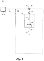
Fig. 1 is a schematic perspective view of a hand drying system constructed in accordance with the present disclosure, showing a connection of the hand drying system to an environmental control system; and -
Fig. 2 shows another hand drying system. - Reference will now be made to the drawings wherein like reference numerals identify similar structural features or aspects of the subject disclosure. For purposes of explanation and illustration, and not limitation, a partial view of an embodiment of a system in accordance with the disclosure is shown in
Fig. 1 and is designated generally byreference character 100. Other embodiments of systems in accordance with the disclosure, or aspects thereof, are provided inFig. 2 as will be described. The systems and methods described herein can be used to provide for litter-free hand drying that reduces or eliminates splatter, e.g. in aircraft lavatories, relative to traditional blower-type hand drying systems. This can provide for cleaner, more sanitary lavatories, and can help reduce the spread of contagions. - In accordance with at least one aspect of this disclosure, a
hand drying system 100 for anaircraft lavatory 102 includes ahand dryer 104. Thehand dryer 104 can be fed by ahand blower tap 106 having aninlet 108 configured to connect to an aircraft environmental control system (ECS) 110. Thehand blower tap 106 can be a conduit or any other suitable means for conveying a flow of pressurized air from the ECS 110. Theinlet 108 receives a flow of conditioned air from the ECS 110, for example from anECS duct 112. For example, the source of pressurized flow for the ECS 110 andhand blower tap 106 can be provided in large part by engine bleed, and can be recirculated throughout an aircraft cabin with blowers. - In certain embodiments, the
inlet 108 can be connected to a gasper system 114 of the ECS 110. Connecting thehand drying system 100 to the ECS 110 and/or the gasper circuit 114 eliminates the need for a separate air supply (e.g. additional fans), which can reduce the weight, size, and noise level (e.g. 65-70 dB or less) of thehand drying system 100. - A
valve 116 is operatively connected to theinlet 108 to selectively block flow from the ECS 110 and allow flow from the ECS 110 through thehand blower tap 106. In embodiments, thevalve 116 can be controlled manually, for example with a push button, or operated through a motion sensor so that touch free operation of the hand drying system is possible. Anoutlet 118 of thehand blower tap 106 can be directed to blow in anair flow direction 120, e.g. directing air downward onto wet hands of a user in theaircraft lavatory 102. The system need not include an air intake opposite thehand blower tap 106 relative to theair flow direction 120. - In embodiments, the
outlet 118 can be connected to a source of air pressurized at 1724 Pa to 3447 Pa (0.25 to 0.5 psi), or the inlet can be connected to a source of air pressurized at 1724 Pa to 6895 Pa (0.25 to 1 psi). Ahumidity filter 122 can be disposed in ahand blower tap 106 upstream of theoutlet 118 for lowering a relative humidity of the flow the air flowing through theoutlet 118 and thehand blower tap 106. In certain embodiments, thehumidity filter 122 can be a high-efficiency particulate absorbing (HEPA) filter, or the filter can be a desiccant dehumidifier to remove excess moisture from the air, decreasing the drying time. In certain embodiments, aheating element 124 can be in thehand blower tap 106 for heating the flow of air through thehand blower tap 106. Theheating element 124 can be a low power heating element, for example outputting less than 100 watts. Heating the air can decrease drying time further, as well as make the air more comfortable for a passenger's hands. It is contemplated that other air treatments may be applied in addition to heating and drying the air, for example scenting the air. - The hand blower tap 106,
valve 116, and the flow of conditioned air can be configured to issue the flow of air from theblower 106 with a flow velocity less than 200 m/s to dry the passenger's hands in less than 20 seconds. For example if theheating element 124 is not activated, 20 second drying time can be achieved with an air velocity between 100 and 120 m/s. When theheating element 124 is active, 20 second drying time can be achieved with an air velocity between 20-50 m/s. However it is possible that a low humidity, low velocity heated air flow can have a drying time of between 10-15 seconds. The low velocity air can decrease the amount of water shed from the passengers hands by about 80 percent as compared to a conventional hand dryer (e.g. a dryer on the ground), decreasing the amount of water that may puddle or splatter beneath thedryer 104. - In certain embodiments, a
hand drying system 200 can have similar elements to that described with respect tosystem 100. For brevity, the description of common elements that have been described above are not repeated. Thesystem 200 can be connected to a source of conditioned air 210 external to the ECS 110, for example by feeding thehand blower tap 106 from a flow of air directly from an ambient environment, e.g. fresh air from outside an aircraft cabin. Because the source of air 210 from the atmosphere is already very low humidity, thesystem 200 does not require any humidity filter in thehand blower tap 106. - In accordance with another aspect of this disclosure, a method includes issuing a flow of air from an aircraft environmental control system (ECS) 110 (or other source of conditioned air 210) through a
hand blower tap 106 in anaircraft lavatory 102 onto a passenger's wet hands, the flow being maintained below 200 m/s, and completely drying the passenger's hands in 20 seconds or less. In embodiments, the method can include heating the flow of air through the hand blower tap 106 (e.g. with heating element 124). In certain embodiments, the method can further include filtering the flow of air with a humidity filter (e.g. filter 122) disposed in the ECS 110 for lowering a relative humidity of the flow of air, if needed. - The methods and systems of the present disclosure, as described above and shown in the drawings, provide for a blower-free hand drying system which is more efficient and more hygienic hand drying. While the apparatus and methods of the subject disclosure have been shown and described, those skilled in the art will readily appreciate that changes and/or modifications may be made thereto without departing from the scope of the claims.
Claims (15)
- A hand drying system (100) for an aircraft lavatory comprising:a hand blower tap (106) with an inlet (108) configured to connect to an aircraft environmental control system, ECS (110) to receive a flow of conditioned air from the ECS (110); anda valve (116) operatively connected to the inlet (108) to selectively block flow from the ECS (110) and allow flow from the ECS (110) through the hand blower tap (106).
- The hand drying system (100) as recited in claim 1, wherein the hand blower tap (106) includes an outlet (118) to direct the flow of conditioned air in an air flow direction, wherein the system is devoid of an air intake opposite the blower tap (106) relative to the air flow direction.
- The hand drying system (100) as recited in claim 1 or 2, wherein the inlet (108) is connected to an ECS supply duct (112) and/or wherein the inlet (108) is connected to a gasper system (114) of the ECS.
- The hand drying system (100) as recited in any preceding claim, wherein a source of the flow of conditioned air is engine bleed air.
- The hand drying system (100) as recited in any preceding claim 1, wherein an amount of water shed is reduced by about 80 percent, and/or wherein a noise level of the hand drying system is about 65-70 dB.
- The hand drying system (100) as recited in any preceding claim, further comprising a humidity filter (122) disposed in a line upstream of the outlet (118) for lowering a relative humidity of the flow of air, optionally wherein the humidity filter (122) is a high-efficiency particulate absorbing (HEPA) filter.
- A hand drying system (100, 200) for an aircraft lavatory comprising:a hand blower tap (106) with an inlet (108) connected to a source of conditioned air (110, 210); anda valve (116) operatively connected to the inlet (108) to selectively block flow from the source of conditioned air (110, 210) and allow flow from the source of conditioned air (110, 210) through the hand blower tap (106),wherein the hand blower tap (106), valve (116), and source of conditioned air (110, 210) are configured to issue a flow of air from the hand blower tap (106) with a flow velocity less than 200 m/s.
- The hand drying system (100, 200) as recited in claim 7, wherein the flow of air from the hand blower tap (106) has a velocity between 25 and 50 m/s.
- The hand drying system (100, 200) as recited in claim 7 or 8, wherein the hand blower tap (106) includes an outlet (118) to direct the flow of conditioned air in an air flow direction, wherein the system (100, 200) is devoid of an air intake opposite the hand blower tap (106) relative to the air flow direction.
- The hand drying system (100, 200) as recited in any of claims 7 to 9, wherein the conditioned flow through the hand blower tap (106) is of a relatively humidity of 10 percent or less such that a humidity filter is not required.
- The hand drying system (200) as recited in any of claims 7 to 10, wherein a source of the flow of conditioned air is engine bleed air.
- The hand drying system as recited in any of claims 7 to 11, further comprising a heating element (124) disposed in the hand blower tap (106) for heating the flow of air through the hand blower tap (106), optionally wherein a power output of the heating element (124) is less than 100 watts.
- A method comprising:issuing a flow of air from an aircraft environmental control system (110), ECS, through a hand blower tap (106) in an aircraft lavatory onto a passenger's wet hands, wherein the flow is maintained below 200 m/s; andcompletely drying the passenger's hands in 20 seconds or less.
- The method as recited in claim 13, further comprising heating the flow of air through the hand blower tap (106).
- The method as recited in claim 13 or 14, further comprising filtering the flow of air with a humidity filter (122) disposed in the ECS (110) for lowering a relative humidity of the flow of air, optionally wherein the hand blower tap (106) includes an outlet (118) directed to blow in an air flow direction, wherein the system is devoid of an air intake opposite the hand blower tap (106) relative to the air flow direction.
Applications Claiming Priority (1)
| Application Number | Priority Date | Filing Date | Title |
|---|---|---|---|
| US17/352,082 US12150601B2 (en) | 2021-06-18 | 2021-06-18 | Lavatory hand dryer |
Publications (1)
| Publication Number | Publication Date |
|---|---|
| EP4104728A1 true EP4104728A1 (en) | 2022-12-21 |
Family
ID=82115967
Family Applications (1)
| Application Number | Title | Priority Date | Filing Date |
|---|---|---|---|
| EP22179734.3A Pending EP4104728A1 (en) | 2021-06-18 | 2022-06-17 | Aircraft lavatory hand dryer |
Country Status (2)
| Country | Link |
|---|---|
| US (2) | US12150601B2 (en) |
| EP (1) | EP4104728A1 (en) |
Cited By (1)
| Publication number | Priority date | Publication date | Assignee | Title |
|---|---|---|---|---|
| US20220400910A1 (en) * | 2021-06-18 | 2022-12-22 | B/E Aerospace, Inc. | Lavatory hand dryer |
Citations (5)
| Publication number | Priority date | Publication date | Assignee | Title |
|---|---|---|---|---|
| US20020109046A1 (en) * | 2001-02-12 | 2002-08-15 | Ooi Kean Khoon | Air heater or dryer apparatus, for use on aircraft |
| EP1909625B1 (en) * | 2005-07-30 | 2009-08-05 | Dyson Technology Limited | Drying apparatus |
| US20120210509A1 (en) * | 2011-02-10 | 2012-08-23 | Airbus Operations Gmbh | Hand drying device and washing stand for an aircraft |
| US20170210473A1 (en) * | 2014-07-29 | 2017-07-27 | Jamco Corporation | Aircraft-installed hand dryer and aircraft lavatory unit |
| US20180251964A1 (en) * | 2017-03-02 | 2018-09-06 | Kohler Co. | Handwashing station |
Family Cites Families (14)
| Publication number | Priority date | Publication date | Assignee | Title |
|---|---|---|---|---|
| US5031337A (en) * | 1988-02-19 | 1991-07-16 | Sloan Valve Company | Automatic hand dryer |
| US5651189A (en) * | 1995-02-10 | 1997-07-29 | Bodi-Blo, Inc. | Portable drying system |
| US6038786A (en) * | 1998-04-16 | 2000-03-21 | Excel Dryer Inc. | Hand dryer |
| ATE357163T1 (en) * | 2001-02-10 | 2007-04-15 | Wella Ag | WARM AIR UNIT |
| KR100668177B1 (en) * | 2004-08-27 | 2007-01-11 | 전남대학교산학협력단 | Hand Dryer Using Photocatalyst Coating Filter |
| GB0515749D0 (en) * | 2005-07-30 | 2005-09-07 | Dyson Technology Ltd | Drying apparatus |
| DE102006042300B4 (en) | 2006-09-08 | 2008-09-04 | Airbus Deutschland Gmbh | Self-contained laundry room for mobile use |
| DE102007046381B4 (en) * | 2007-09-27 | 2011-07-28 | Airbus Operations GmbH, 21129 | Fuel cell system with suction for an aircraft, method for operating the fuel cell system and aircraft with such a fuel cell system |
| EP2403728B1 (en) * | 2009-03-04 | 2021-06-23 | B/E Aerospace, Inc. | Aircraft galley cart compartment with point-of-use air chiller |
| US10455992B2 (en) | 2016-09-20 | 2019-10-29 | The Boeing Company | Hand dryer having managed air flow |
| US10264931B2 (en) | 2016-09-23 | 2019-04-23 | The Boeing Company | Hand drying systems and methods |
| US20210289996A1 (en) * | 2020-03-19 | 2021-09-23 | Lg Electronics Inc. | Drying apparatus and related methods |
| US12150601B2 (en) * | 2021-06-18 | 2024-11-26 | B/E Aerospace, Inc. | Lavatory hand dryer |
| US12258129B2 (en) * | 2022-10-03 | 2025-03-25 | B/E Aerospace, Inc. | Floor dryer in an aircraft lavatory |
-
2021
- 2021-06-18 US US17/352,082 patent/US12150601B2/en active Active
-
2022
- 2022-06-17 EP EP22179734.3A patent/EP4104728A1/en active Pending
-
2024
- 2024-10-23 US US18/924,534 patent/US20250040767A1/en active Pending
Patent Citations (5)
| Publication number | Priority date | Publication date | Assignee | Title |
|---|---|---|---|---|
| US20020109046A1 (en) * | 2001-02-12 | 2002-08-15 | Ooi Kean Khoon | Air heater or dryer apparatus, for use on aircraft |
| EP1909625B1 (en) * | 2005-07-30 | 2009-08-05 | Dyson Technology Limited | Drying apparatus |
| US20120210509A1 (en) * | 2011-02-10 | 2012-08-23 | Airbus Operations Gmbh | Hand drying device and washing stand for an aircraft |
| US20170210473A1 (en) * | 2014-07-29 | 2017-07-27 | Jamco Corporation | Aircraft-installed hand dryer and aircraft lavatory unit |
| US20180251964A1 (en) * | 2017-03-02 | 2018-09-06 | Kohler Co. | Handwashing station |
Cited By (2)
| Publication number | Priority date | Publication date | Assignee | Title |
|---|---|---|---|---|
| US20220400910A1 (en) * | 2021-06-18 | 2022-12-22 | B/E Aerospace, Inc. | Lavatory hand dryer |
| US12150601B2 (en) * | 2021-06-18 | 2024-11-26 | B/E Aerospace, Inc. | Lavatory hand dryer |
Also Published As
| Publication number | Publication date |
|---|---|
| US20220400910A1 (en) | 2022-12-22 |
| US12150601B2 (en) | 2024-11-26 |
| US20250040767A1 (en) | 2025-02-06 |
Similar Documents
| Publication | Publication Date | Title |
|---|---|---|
| US11129505B2 (en) | Hand dryer having managed air flow | |
| US5695396A (en) | Ventilating system for reducing contaminations in the air of an aircraft | |
| US6092794A (en) | Secondary air humidification handler | |
| US20250040767A1 (en) | Lavatory hand dryer | |
| US11447256B2 (en) | Humidifier especially for aircrafts | |
| EP1723876A4 (en) | AIR CONDITIONING SEAT AND AIR CONDITIONING SYSTEM USING THE SAME | |
| CN102369141B (en) | Air conditioner having an air dehumidifying device and method for operating such an air conditioner | |
| JPS60228832A (en) | Air capacity variable type air-conditioning system | |
| CN114426100A (en) | Ventilation system and method for an interior compartment of a vehicle | |
| JP4232003B2 (en) | Grain pneumatic transport method and apparatus | |
| US12435901B2 (en) | Critical area recirculation and exhaust system | |
| CN110542171A (en) | A concealed fresh air system | |
| JP3851609B2 (en) | Control method for multiple air conditioners | |
| CN101365916A (en) | Air conditioning system with low energy consumption | |
| US20190309985A1 (en) | System and Method of Conditioning Recycled Air During Building Construction | |
| JPH03148543A (en) | Ventilation device | |
| CN109747868A (en) | An energy-saving aerospace high-efficiency ventilation device | |
| JPH11173621A (en) | Central ventilator | |
| JP7174901B2 (en) | ventilation air conditioning system | |
| JP2781514B2 (en) | Simultaneous supply and exhaust ventilation | |
| JP6814934B2 (en) | Bathroom air conditioner | |
| US20060130662A1 (en) | Air filter and method of filtering air in central heating and air conditioning system | |
| JPS5929935A (en) | Exhaust apparatus for cookery | |
| JP2003065574A (en) | Air purifying system in smoking booth | |
| EP1360921A3 (en) | Fine filter situated in exhaust air stream of vacuum cleaner, and corresponding vacuum cleaner |
Legal Events
| Date | Code | Title | Description |
|---|---|---|---|
| PUAI | Public reference made under article 153(3) epc to a published international application that has entered the european phase |
Free format text: ORIGINAL CODE: 0009012 |
|
| STAA | Information on the status of an ep patent application or granted ep patent |
Free format text: STATUS: THE APPLICATION HAS BEEN PUBLISHED |
|
| AK | Designated contracting states |
Kind code of ref document: A1 Designated state(s): AL AT BE BG CH CY CZ DE DK EE ES FI FR GB GR HR HU IE IS IT LI LT LU LV MC MK MT NL NO PL PT RO RS SE SI SK SM TR |
|
| STAA | Information on the status of an ep patent application or granted ep patent |
Free format text: STATUS: REQUEST FOR EXAMINATION WAS MADE |
|
| 17P | Request for examination filed |
Effective date: 20230615 |
|
| RBV | Designated contracting states (corrected) |
Designated state(s): AL AT BE BG CH CY CZ DE DK EE ES FI FR GB GR HR HU IE IS IT LI LT LU LV MC MK MT NL NO PL PT RO RS SE SI SK SM TR |
|
| P01 | Opt-out of the competence of the unified patent court (upc) registered |
Effective date: 20230922 |
|
| STAA | Information on the status of an ep patent application or granted ep patent |
Free format text: STATUS: EXAMINATION IS IN PROGRESS |
|
| 17Q | First examination report despatched |
Effective date: 20240611 |