EP4104089B1 - Method for validating radio frequency identification number - Google Patents
Method for validating radio frequency identification number Download PDFInfo
- Publication number
- EP4104089B1 EP4104089B1 EP21753602.8A EP21753602A EP4104089B1 EP 4104089 B1 EP4104089 B1 EP 4104089B1 EP 21753602 A EP21753602 A EP 21753602A EP 4104089 B1 EP4104089 B1 EP 4104089B1
- Authority
- EP
- European Patent Office
- Prior art keywords
- transponder
- memory
- telegram
- signature
- rfid
- Prior art date
- Legal status (The legal status is an assumption and is not a legal conclusion. Google has not performed a legal analysis and makes no representation as to the accuracy of the status listed.)
- Active
Links
Images




Classifications
-
- G—PHYSICS
- G06—COMPUTING OR CALCULATING; COUNTING
- G06K—GRAPHICAL DATA READING; PRESENTATION OF DATA; RECORD CARRIERS; HANDLING RECORD CARRIERS
- G06K19/00—Record carriers for use with machines and with at least a part designed to carry digital markings
- G06K19/06—Record carriers for use with machines and with at least a part designed to carry digital markings characterised by the kind of the digital marking, e.g. shape, nature, code
- G06K19/067—Record carriers with conductive marks, printed circuits or semiconductor circuit elements, e.g. credit or identity cards also with resonating or responding marks without active components
- G06K19/07—Record carriers with conductive marks, printed circuits or semiconductor circuit elements, e.g. credit or identity cards also with resonating or responding marks without active components with integrated circuit chips
- G06K19/073—Special arrangements for circuits, e.g. for protecting identification code in memory
-
- G—PHYSICS
- G06—COMPUTING OR CALCULATING; COUNTING
- G06K—GRAPHICAL DATA READING; PRESENTATION OF DATA; RECORD CARRIERS; HANDLING RECORD CARRIERS
- G06K7/00—Methods or arrangements for sensing record carriers, e.g. for reading patterns
- G06K7/08—Methods or arrangements for sensing record carriers, e.g. for reading patterns by means detecting the change of an electrostatic or magnetic field, e.g. by detecting change of capacitance between electrodes
- G06K7/082—Methods or arrangements for sensing record carriers, e.g. for reading patterns by means detecting the change of an electrostatic or magnetic field, e.g. by detecting change of capacitance between electrodes using inductive or magnetic sensors
- G06K7/083—Methods or arrangements for sensing record carriers, e.g. for reading patterns by means detecting the change of an electrostatic or magnetic field, e.g. by detecting change of capacitance between electrodes using inductive or magnetic sensors inductive
- G06K7/086—Methods or arrangements for sensing record carriers, e.g. for reading patterns by means detecting the change of an electrostatic or magnetic field, e.g. by detecting change of capacitance between electrodes using inductive or magnetic sensors inductive sensing passive circuit, e.g. resonant circuit transponders
-
- G—PHYSICS
- G06—COMPUTING OR CALCULATING; COUNTING
- G06K—GRAPHICAL DATA READING; PRESENTATION OF DATA; RECORD CARRIERS; HANDLING RECORD CARRIERS
- G06K19/00—Record carriers for use with machines and with at least a part designed to carry digital markings
- G06K19/06—Record carriers for use with machines and with at least a part designed to carry digital markings characterised by the kind of the digital marking, e.g. shape, nature, code
- G06K19/08—Record carriers for use with machines and with at least a part designed to carry digital markings characterised by the kind of the digital marking, e.g. shape, nature, code using markings of different kinds or more than one marking of the same kind in the same record carrier, e.g. one marking being sensed by optical and the other by magnetic means
- G06K19/10—Record carriers for use with machines and with at least a part designed to carry digital markings characterised by the kind of the digital marking, e.g. shape, nature, code using markings of different kinds or more than one marking of the same kind in the same record carrier, e.g. one marking being sensed by optical and the other by magnetic means at least one kind of marking being used for authentication, e.g. of credit or identity cards
- G06K19/14—Record carriers for use with machines and with at least a part designed to carry digital markings characterised by the kind of the digital marking, e.g. shape, nature, code using markings of different kinds or more than one marking of the same kind in the same record carrier, e.g. one marking being sensed by optical and the other by magnetic means at least one kind of marking being used for authentication, e.g. of credit or identity cards the marking being sensed by radiation
- G06K19/145—Record carriers for use with machines and with at least a part designed to carry digital markings characterised by the kind of the digital marking, e.g. shape, nature, code using markings of different kinds or more than one marking of the same kind in the same record carrier, e.g. one marking being sensed by optical and the other by magnetic means at least one kind of marking being used for authentication, e.g. of credit or identity cards the marking being sensed by radiation at least one of the further markings being adapted for galvanic or wireless sensing, e.g. an RFID tag with both a wireless and an optical interface or memory, or a contact type smart card with ISO 7816 contacts and an optical interface or memory
-
- G—PHYSICS
- G06—COMPUTING OR CALCULATING; COUNTING
- G06K—GRAPHICAL DATA READING; PRESENTATION OF DATA; RECORD CARRIERS; HANDLING RECORD CARRIERS
- G06K7/00—Methods or arrangements for sensing record carriers, e.g. for reading patterns
- G06K7/10—Methods or arrangements for sensing record carriers, e.g. for reading patterns by electromagnetic radiation, e.g. optical sensing; by corpuscular radiation
- G06K7/10009—Methods or arrangements for sensing record carriers, e.g. for reading patterns by electromagnetic radiation, e.g. optical sensing; by corpuscular radiation sensing by radiation using wavelengths larger than 0.1 mm, e.g. radio-waves or microwaves
- G06K7/10297—Methods or arrangements for sensing record carriers, e.g. for reading patterns by electromagnetic radiation, e.g. optical sensing; by corpuscular radiation sensing by radiation using wavelengths larger than 0.1 mm, e.g. radio-waves or microwaves arrangements for handling protocols designed for non-contact record carriers such as RFIDs NFCs, e.g. ISO/IEC 14443 and 18092
Definitions
- this specification relates to a method for producing an RFID transponder and in particular to an RFID transponder with authentication data. Additionally, the specification relates to a method for authenticating an RFID with a standalone RFID scanner. More specifically, this disclosure presents a method to produce and validate authenticated ISO 11784/11785 transponders, for example.
- the ISO 11784/11785:1996 standards specify the radio frequency identification (RFID) signal and data structure for animal identification.
- RFID radio frequency identification
- the standards lack the specifications for authentication and leave the identification numbers vulnerable to cloning.
- the existing ISO 11784/11785 radio frequency identification technologies rely on the manufacturers to guarantee the uniqueness of each animal identification number.
- European Patent Application EP2677473 A1 discloses a transponder authentication method based on a transponder-specific originality signature. The method involves providing a transponder with a transponder-specific identifier, and providing the transponder with a signature utilized for authentication of the transponder.
- the signature is generated by signing a part of the transponder-specific identifier, where the signature is stored in a hidden memory of the transponder and generated by signing a part of the transponder-specific identifier with a private key of a private-public key pair.
- US Patent US10127413 B2 discloses an RFID tag authentication means that performs authentication of a telegram written in the RFID tag.
- US Patent Application US2008/0303667 A1 discloses a signing method for radio frequency identification application, involving generating signature for tag based on identifier and public key, and storing identifier and signature in tag.
- This specification describes means for manufacturers to produce RFID transponders, e.g., ISO 11784/11785 compliant transponders, with authentication signature using commercially-available transponders and RFID programmers. This specification also describes methods to validate the authentication signature using RFID scanners capable of reading the internal memory of a transponder, thereby authenticating the transponder.
- RFID radio frequency identification
- the default telegram includes an identification code and a signature indicator.
- the subject matter features a passive integrated transponder (PIT) tag including the transponder.
- PIT passive integrated transponder
- the subject matter features a collar tag including the transponder.
- Implementations of the method can include one or more of the following features and/or features of other aspects.
- the memory can include a unique identification (UID) code independently established by a third party and the method can further include retrieving the UID code by transmitting the memory-read signal from the scanner to the transponder.
- the signature can be computationally authenticated based on the default telegram and the UID code.
- the signature can be generated with the UID code and the default telegram.
- the memory-read signal can be transmitted by the scanner after retrieving the default telegram.
- the scanner can transmit the memory-read signal in response to confirming a signature indicator contained in the default telegram.
- the entire signature can be retrieved upon transmitting the memory-read signal from the scanner to the transponder.
- a portion of the signature is retrieved with the default telegram.
- the method can include validating the transponder upon authentication of the signature.
- the transponder can reside within an animal during retrieval of the default telegram and the signature.
- the method can include identifying the animal after authenticating the signature.
- the disclosed method includes several steps and the relation of one or more of such steps with respect to each of the others, and the apparatus embodying features of construction, combinations of elements and arrangement of parts that are adapted to affect such steps, all is exemplified in the following detailed disclosure, and the scope of the invention will be indicated in the claims.
- RFID transponders Many systems are designed around the capabilities of RFID transponders, such as licensing and registration of animals, certification of veterinary health certificates, time and attendance systems, and access control, each of which generally implicitly rely of the integrity of the transponder identification code.
- the secured transponder technologies disclosed herein advance and promote the objects of identification by frustrating illicit duplication or counterfeiting of transponders placed into service and further strengthens such systems by creating accountability and preventing repudiation of a transponder.
- the secured transponder technologies disclosed herein can advance identification, e.g. animal identification, technologies by enabling signature validation for transponder authentication.
- the transponders can be used as certificates of authenticity, e.g. in a similar manner to those used for luxury watches, art, memorabilia, etc.
- the disclosed technologies relate to a method and system to prevent fraudulent production of a radiofrequency identification (RFID) transponder.
- RFID radiofrequency identification
- the technology can include a signature indicator in the default-read telegram and storing a read-only authentication signature in the internal memory of the transponder.
- the RFID transponder is compliant with an ISO standard, such as the ISO 11784/11785 standard.
- the transponders can be used for animal identification.
- the transponders can be embedded or attached to a variety of articles, depending on the end use.
- the transponder can be embedded in a tag, e.g., for attaching to an animal, such as a passive integrated transponder (PIT) tag or a collar tag.
- the transponder can be enclosed in a nail or attached to an adhesive substrate.
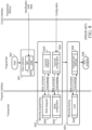
- transponder 120 includes a radio frequency transceiver 121 and a memory 122.
- RF transceiver 121 generally includes control circuitry (e.g., composed of one or more integrated circuits) and an antenna.
- Memory 122 includes internal memory 123 (e.g., read only memory) and field-programmable memory 124.
- Memory 122 is in communication with RF transceiver 121, which receives RF signals 132 (e.g., from an RF scanner 140) and transmits RF signals 130 (e.g., to RF scanner 140).
- the transmitted RF signals 130 includes information stored in memory 122 that uniquely identifies transponder 120.
- the information includes a default telegram stored in field-programmable memory 124 that is transmitted by transponder 120 automatically upon activation by transponder 140.
- Field-programmable memory 124 also includes a signature generated using, at least, a portion of the default telegram (e.g., with just part of the default telegram or with the entire default telegram).
- Internal memory 123 can store information such as a unique identification (ID) code independently established by a third party, such as a manufacturer of the integrated circuit of the memory.
- ID unique identification
- the signature can adopt any public-private key encryption methods, such as AES, ECDSA, and RSA.
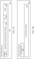
- FIGS. 1B and 1C show a conventional 128-bit ISO FDX telegram 101 defined in ISO 11785:1996 and a conventional 64-bit identification code data content 106 defined in 11784:1996, 11784 Amd. 1:2004, and 11784 Amd. 2:2010, respectively.
- Identification code 106 is part of the data making up telegram 101.
- FIG. 1C An index used in FIG. 1C is provided in Table 1.
- identification memory 205 stores an ISO 11784/11785 telegram and its content is continuously transmitted by the transponder whenever the transponder is activated.
- the authentication memory 206 stores the authentication data and its content is only transmitted by the transponder, in general, once every time a memory read command is received by the transponder. In certain instances, multiple read commands may be needed to retrieve a complete authentication.
- a conventional scanner without authentication capabilities will follow the conventional identification process flow shown in FIG. 6 and only have access to the ISO telegram stored in the identification memory 205.
- the signature 204 is stored in a baseline configuration.
- the complete signature 204 is stored in the internal memory 206 of the transponder with no part of it appearing in the telegram 205 shown in FIG. 2A .
- the RFID scanner has to transmit memory read commands 508 to the transponder, as shown in FIG. 7 .
- a signature indicator 112 can be introduced to the user information field 112 of an identification code 113 specified in the ISO 11784:1996/Amd.1:2004 standard.
- a signature 301 & 303 is stored in a partial signature trailer configuration.
- a portion of the signature is stored in the telegram trailer 301.
- the telegram trailer 301 shown in FIG. 4A , is transmitted as a part of the ISO 11784/11785 telegram 302. All standard conforming scanners can read and collect this part of the signature during the conventional transponder scanning process shown in FIG. 6 .
- the scanner send an activation signal (402) which causes the transponder to transmit the default telegram 442.
- the scanner receives and reads the telegram (403). This completes the scan (405).
- the transponder is switched off when the activation field is no longer present.
- the remaining portion of the signature 303 is stored in the internal memory 206 of the transponder.
- the RFID scanner has to transmit memory read commands 508 to the transponder, as shown in FIG. 7 .
- part of the signature can be stored in the telegram's identification code.
- FIG. 5 shows an implementation of a telegram's identification code 802 in which part of the signature is included in user information field 801.
- an authentication signature generated from the transponder UID 203 and the animal identification number 111 is introduced to every transponder for authentication.
- a scanner can validate the authenticity of the signature by using the animal identification number 111, a known public key, and the transponder UID 203 as the input parameters to the validation function.
- the RF scanner has to perform additional data extraction 505, 506 and transponder interrogation 508.
- the scanner attempts to detect 505 a signature indicator 112 in the telegram 202/302's user information field 107.
- the absence 505N of a signature indicator 112 immediately categorizes 513 the transponder as "not signed". No authentication is possible for such transponders. This is the case for existing conventional ISO transponders in the market.
- the scanner will extract 506 the partial signature from the telegram trailer 301 for signed transponders using the partial signature trailer 301 storage configuration. Afterwards, the scanner reads the transponder UID 203 and the remaining signature data 204, 303 from the transponder by sending multiple memory read commands 508. When both the transponder UID 203 and the complete signature 204, 301 & 303 are collected via UID and signature data transmission 545 from the transponder, the scanner can validate 510, 511 the signature stored in the transponder using the public key, the identification code 111, and the transponder UID 203 as decryption parameters. The validation process described above is shown in FIG. 7 . When validating, the UID and signature read orders can be interchanged.
- FIG. 8 is a flowchart of a programming process of a conventional ISO transponder.
- an ISO 11784/11785 compliant programmer starts 601 with data collection 602 including obtaining an identification code 609 from programmer memory.
- the programmer writes the transponder configuration 604, the telegram 605, and the transponder lock 606 in the sequence to transponder in a telegram write (643), configuration write (642) and lock (644) steps, as shown in FIG. 8 .
- the production of signed transponders requires additional steps to interrogate the transponder 704 and compute the signature 706.
- FIG. 9 is a flowchart of a programming process of a signed transponder, in accordance with the disclosed technologies.
- the programmer needs the additional steps of reading the UID of the transponder 704 and generating the authentication signature 706 before programming both the telegram and the signature 709.
- the programmer uses a private key, the transponder UID 203, the identification code 111, and a random salt as parameters for signature generation 706.
- the programmer can then write the configuration 708, the telegram 709, the signature 709, and the lock configuration 710 to the transponder in the sequence shown in FIG. 9 .
- Steps in the process shown in FIG. 9 that are common to the process shown in FIG. 8 have like labels, advanced by 100. E.g., in FIG. 8 the process starts at 601, in FIG. 9 the process starts at 701.
- the configuration and telegram write orders can be interchanged.
- this specification describes means for manufacturers to produce ISO 11784/11785 compliant transponders with authentication signature using commonly available transponders and RFID programmers. This specification also describes a method to validate the authentication signature using RFID scanners with transponder programming features.
- Embodiments of the subject matter and the functional operations described in this specification can be implemented in digital electronic circuitry, in tangibly-embodied computer software or firmware, in computer hardware, including the structures disclosed in this specification and their structural equivalents, or in combinations of one or more of them.
- Embodiments of the subject matter described in this specification can be implemented as one or more computer programs, i.e., one or more modules of computer program instructions encoded on a tangible non-transitory storage medium for execution by, or to control the operation of, data processing apparatus.
- the computer storage medium can be a machine-readable storage device, a machine-readable storage substrate, a random or serial access memory device, or a combination of one or more of them.
- the program instructions can be encoded on an artificially-generated propagated signal, e.g., a machine-generated electrical, optical, or electromagnetic signal, that is generated to encode information for transmission to suitable receiver apparatus for execution by a data processing apparatus.
- data processing apparatus refers to data processing hardware and encompasses all kinds of apparatus, devices, and machines for processing data, including by way of example a programmable processor, a computer, or multiple processors or computers.
- the apparatus can also be, or further include, special purpose logic circuitry, e.g., an FPGA (field programmable gate array) or an ASIC (application-specific integrated circuit).
- the apparatus can optionally include, in addition to hardware, code that creates an execution environment for computer programs, e.g., code that constitutes processor firmware, a protocol stack, a database management system, an operating system, or a combination of one or more of them.
- a computer program which may also be referred to or described as a program, software, a software application, an app, a module, a software module, a script, or code, can be written in any form of programming language, including compiled or interpreted languages, or declarative or procedural languages; and it can be deployed in any form, including as a stand-alone program or as a module, component, subroutine, or other unit suitable for use in a computing environment.
- a program may, but need not, correspond to a file in a file system.
- a program can be stored in a portion of a file that holds other programs or data, e.g., one or more scripts stored in a markup language document, in a single file dedicated to the program in question, or in multiple coordinated files, e.g., files that store one or more modules, sub-programs, or portions of code.
- a computer program can be deployed to be executed on one computer or on multiple computers that are located at one site or distributed across multiple sites and interconnected by a data communication network.
- the processes and logic flows described in this specification can be performed by one or more programmable computers executing one or more computer programs to perform functions by operating on input data and generating output.
- the processes and logic flows can also be performed by special purpose logic circuitry, e.g., an FPGA or an ASIC, or by a combination of special purpose logic circuitry and one or more programmed computers.
- Computers suitable for the execution of a computer program can be based on general or special purpose microprocessors or both, or any other kind of central processing unit.
- a central processing unit will receive instructions and data from a read-only memory or a random access memory or both.
- the essential elements of a computer are a central processing unit for performing or executing instructions and one or more memory devices for storing instructions and data.
- the central processing unit and the memory can be supplemented by, or incorporated in, special purpose logic circuitry.
- a computer will also include, or be operatively coupled to receive data from or transfer data to, or both, one or more mass storage devices for storing data, e.g., magnetic, magneto-optical disks, or optical disks.
- a computer need not have such devices.
- a computer can be embedded in another device, e.g., a mobile telephone, a personal digital assistant (PDA), a mobile audio or video player, a game console, a Global Positioning System (GPS) receiver, or a portable storage device, e.g., a universal serial bus (USB) flash drive, to name just a few.
- PDA personal digital assistant
- GPS Global Positioning System
- USB universal serial bus
- Computer-readable media suitable for storing computer program instructions and data include all forms of non-volatile memory, media and memory devices, including by way of example semiconductor memory devices, e.g., EPROM, EEPROM, and flash memory devices; magnetic disks, e.g., internal hard disks or removable disks; magneto-optical disks; and CD-ROM and DVD-ROM disks.
- semiconductor memory devices e.g., EPROM, EEPROM, and flash memory devices
- magnetic disks e.g., internal hard disks or removable disks
- magneto-optical disks e.g., CD-ROM and DVD-ROM disks.
- embodiments of the subject matter described in this specification can be implemented on a computer having a display device, e.g., a CRT (cathode ray tube) or LCD (liquid crystal display) monitor, for displaying information to the user and a keyboard and a pointing device, e.g., a mouse or a trackball, by which the user can provide input to the computer.
- a display device e.g., a CRT (cathode ray tube) or LCD (liquid crystal display) monitor
- keyboard and a pointing device e.g., a mouse or a trackball
- Other kinds of devices can be used to provide for interaction with a user as well; for example, feedback provided to the user can be any form of sensory feedback, e.g., visual feedback, auditory feedback, or tactile feedback; and input from the user can be received in any form, including acoustic, speech, or tactile input.
- a computer can interact with a user by sending documents to and receiving documents from a device that is used by the user; for example, by sending web pages to a web browser on a user's device in response to requests received from the web browser.
- a computer can interact with a user by sending text messages or other forms of message to a personal device, e.g., a smartphone that is running a messaging application, and receiving responsive messages from the user in return.
Landscapes
- Engineering & Computer Science (AREA)
- Physics & Mathematics (AREA)
- Theoretical Computer Science (AREA)
- General Physics & Mathematics (AREA)
- Computer Networks & Wireless Communication (AREA)
- Health & Medical Sciences (AREA)
- Toxicology (AREA)
- Artificial Intelligence (AREA)
- Computer Vision & Pattern Recognition (AREA)
- Computer Security & Cryptography (AREA)
- General Health & Medical Sciences (AREA)
- Electromagnetism (AREA)
- Computer Hardware Design (AREA)
- General Engineering & Computer Science (AREA)
- Microelectronics & Electronic Packaging (AREA)
- Storage Device Security (AREA)
- Mobile Radio Communication Systems (AREA)
- Near-Field Transmission Systems (AREA)
- Management, Administration, Business Operations System, And Electronic Commerce (AREA)
Description
- Generally, this specification relates to a method for producing an RFID transponder and in particular to an RFID transponder with authentication data. Additionally, the specification relates to a method for authenticating an RFID with a standalone RFID scanner. More specifically, this disclosure presents a method to produce and validate authenticated ISO 11784/11785 transponders, for example.
- The ISO 11784/11785:1996 standards specify the radio frequency identification (RFID) signal and data structure for animal identification. The standards lack the specifications for authentication and leave the identification numbers vulnerable to cloning. The existing ISO 11784/11785 radio frequency identification technologies rely on the manufacturers to guarantee the uniqueness of each animal identification number.
- However, with the availability of programmable transponders, the animal identification numbers can easily be cloned by a standard RFID programmer. While existing technologies like NXP's Originality Signature store and retrieve encrypted signatures within the transponder, they use manufacturer specific transponder hardware logic and scanner software. European Patent Application
EP2677473 A1 discloses a transponder authentication method based on a transponder-specific originality signature. The method involves providing a transponder with a transponder-specific identifier, and providing the transponder with a signature utilized for authentication of the transponder. The signature is generated by signing a part of the transponder-specific identifier, where the signature is stored in a hidden memory of the transponder and generated by signing a part of the transponder-specific identifier with a private key of a private-public key pair.
US PatentUS10127413 B2
US Patent ApplicationUS2008/0303667 A1 discloses a signing method for radio frequency identification application, involving generating signature for tag based on identifier and public key, and storing identifier and signature in tag. - The invention is defined by the appended claims. This specification describes means for manufacturers to produce RFID transponders, e.g., ISO 11784/11785 compliant transponders, with authentication signature using commercially-available transponders and RFID programmers. This specification also describes methods to validate the authentication signature using RFID scanners capable of reading the internal memory of a transponder, thereby authenticating the transponder.
- In general, one innovative aspect of the subject matter described in this specification can be embodied in a radio frequency identification (RFID) transponder according to claim 1.
- In some implementations, the default telegram includes an identification code and a signature indicator.
- In another aspect, the subject matter features a passive integrated transponder (PIT) tag including the transponder.
- In yet another aspect, the subject matter features a collar tag including the transponder.
- In general, another innovative aspect of the subject matter described in this specification can be embodied in a method according to claim 5.
- Implementations of the method can include one or more of the following features and/or features of other aspects. For example, the memory can include a unique identification (UID) code independently established by a third party and the method can further include retrieving the UID code by transmitting the memory-read signal from the scanner to the transponder. The signature can be computationally authenticated based on the default telegram and the UID code. The signature can be generated with the UID code and the default telegram.
- The memory-read signal can be transmitted by the scanner after retrieving the default telegram. The scanner can transmit the memory-read signal in response to confirming a signature indicator contained in the default telegram.
- The entire signature can be retrieved upon transmitting the memory-read signal from the scanner to the transponder. In certain implementations, a portion of the signature is retrieved with the default telegram.
- The method can include validating the transponder upon authentication of the signature.
- The transponder can reside within an animal during retrieval of the default telegram and the signature. The method can include identifying the animal after authenticating the signature.
- Accordingly, the disclosed method includes several steps and the relation of one or more of such steps with respect to each of the others, and the apparatus embodying features of construction, combinations of elements and arrangement of parts that are adapted to affect such steps, all is exemplified in the following detailed disclosure, and the scope of the invention will be indicated in the claims.
- Many systems are designed around the capabilities of RFID transponders, such as licensing and registration of animals, certification of veterinary health certificates, time and attendance systems, and access control, each of which generally implicitly rely of the integrity of the transponder identification code.
- The secured transponder technologies disclosed herein advance and promote the objects of identification by frustrating illicit duplication or counterfeiting of transponders placed into service and further strengthens such systems by creating accountability and preventing repudiation of a transponder.
- Among other advantages, the secured transponder technologies disclosed herein can advance identification, e.g. animal identification, technologies by enabling signature validation for transponder authentication. In some implementations, the transponders can be used as certificates of authenticity, e.g. in a similar manner to those used for luxury watches, art, memorabilia, etc.
- The details of one or more embodiments of the subject matter of this specification are set forth in the accompanying drawings and the description below. Other features, aspects, and advantages of the subject matter will become apparent from the description, the drawings, and the claims.
-
-
FIG. 1A is a schematic diagram showing aspects of a RFID transponder. -
FIG. 1B shows a conventional 128-bit ISO Full Duplex transmission (FDX) telegram defined in ISO 11785:1996. -
FIG. 1C shows a conventional 64-bit identification code data content defined in ISO 11784:1996, ISO 11784 Amd.1:2004, and ISO 11784 Amd.2:2010. -
FIGS. 2A-2B show aspects of example memory content of the disclosed transponder featuring a signature indicator included with identification data and an authentication signature included entirely with authentication data. -
FIG. 3 shows identification code data compliant with ISO 11784 that includes a signature indicator. -
FIGS. 4A-4B show aspects of example memory content of the disclosed transponder with a partial signature trailer in the identification data and part of the signature is included with authentication data. -
FIG. 5 shows identification code data compliant with ISO 11784 that includes part of a signature. -
FIG. 6 is a flowchart of a scanning process of a conventional ISO transponder. -
FIG. 7 is a flowchart of an example scanning process of the disclosed ISO transponder. -
FIG. 8 is a flowchart of a programming process of a conventional ISO transponder. -
FIG. 9 is a flowchart of an example programming process of the disclosed ISO transponder. - Like reference numbers and designations in the various drawings indicate like elements.
- In general, the disclosed technologies relate to a method and system to prevent fraudulent production of a radiofrequency identification (RFID) transponder. For example, the technology can include a signature indicator in the default-read telegram and storing a read-only authentication signature in the internal memory of the transponder. The RFID transponder is compliant with an ISO standard, such as the ISO 11784/11785 standard. Among other uses, the transponders can be used for animal identification. The transponders can be embedded or attached to a variety of articles, depending on the end use. For example, the transponder can be embedded in a tag, e.g., for attaching to an animal, such as a passive integrated transponder (PIT) tag or a collar tag. In some embodiments, the transponder can be enclosed in a nail or attached to an adhesive substrate.
- An example RFID transponder for implementing the method is shown in
FIG. 1A . Here,transponder 120 includes aradio frequency transceiver 121 and amemory 122.RF transceiver 121 generally includes control circuitry (e.g., composed of one or more integrated circuits) and an antenna.Memory 122 includes internal memory 123 (e.g., read only memory) and field-programmable memory 124.Memory 122 is in communication withRF transceiver 121, which receives RF signals 132 (e.g., from an RF scanner 140) and transmits RF signals 130 (e.g., to RF scanner 140). Generally, the transmitted RF signals 130 includes information stored inmemory 122 that uniquely identifiestransponder 120. The information includes a default telegram stored in field-programmable memory 124 that is transmitted bytransponder 120 automatically upon activation bytransponder 140. Field-programmable memory 124 also includes a signature generated using, at least, a portion of the default telegram (e.g., with just part of the default telegram or with the entire default telegram).Internal memory 123 can store information such as a unique identification (ID) code independently established by a third party, such as a manufacturer of the integrated circuit of the memory. - In general, the signature can adopt any public-private key encryption methods, such as AES, ECDSA, and RSA.
- Examples of specific protocols for partitioning and retrieving information stored, including the signature, in
memory 122 are presented below. While the examples use the ISO 11784/11785 standard, more generally, the innovative concepts disclosed can be applied to other standards too. -
FIGS. 1B and 1C show a conventional 128-bitISO FDX telegram 101 defined in ISO 11785:1996 and a conventional 64-bit identificationcode data content 106 defined in 11784:1996, 11784 Amd. 1:2004, and 11784 Amd. 2:2010, respectively.Identification code 106 is part of the data making uptelegram 101. - An index used in
FIG. 1C is provided in Table 1.Field Field Name Field value Meaning A Non-animal identification 0 Animal 1 Non-animal a Reference to user data inside (RUDI) 0 No user data 1 Advanced transponder D Data in telegram trailer 0 ID-only 1 Data in telegram trailer - Turning now to RFID tags that include a signature for authentication, generally the transponder memory is partitioned into two segments: identification data and authentication data. Referring to an example in
FIGS. 2A and 2B ,identification memory 205 stores an ISO 11784/11785 telegram and its content is continuously transmitted by the transponder whenever the transponder is activated. Theauthentication memory 206 stores the authentication data and its content is only transmitted by the transponder, in general, once every time a memory read command is received by the transponder. In certain instances, multiple read commands may be needed to retrieve a complete authentication. A conventional scanner without authentication capabilities will follow the conventional identification process flow shown inFIG. 6 and only have access to the ISO telegram stored in theidentification memory 205. - In the example implementation shown in
FIGS. 2A-2B , thesignature 204 is stored in a baseline configuration. In the baseline signature storage format shown inFIG. 2B , thecomplete signature 204 is stored in theinternal memory 206 of the transponder with no part of it appearing in thetelegram 205 shown inFIG. 2A . To retrieve thecomplete signature 204, the RFID scanner has to transmit memory read commands 508 to the transponder, as shown inFIG. 7 . - Referring to
FIG. 3 , for the implementation shown inFIGS. 2A-2B , asignature indicator 112 can be introduced to theuser information field 112 of anidentification code 113 specified in the ISO 11784:1996/Amd.1:2004 standard. - In some implementations, at least part of a signature can be stored as part of the identification data. For example, referring to
FIGS. 4A-4B , a signature 301 & 303 is stored in a partial signature trailer configuration. In the partial-signature trailer format shown here, a portion of the signature is stored in the telegram trailer 301. The telegram trailer 301, shown inFIG. 4A , is transmitted as a part of the ISO 11784/11785telegram 302. All standard conforming scanners can read and collect this part of the signature during the conventional transponder scanning process shown inFIG. 6 . In particular, at the start of a scan (401), the scanner send an activation signal (402) which causes the transponder to transmit thedefault telegram 442. The scanner receives and reads the telegram (403). This completes the scan (405). The transponder is switched off when the activation field is no longer present. - The remaining portion of the
signature 303 is stored in theinternal memory 206 of the transponder. To retrieve the complete signature 301 & 303, the RFID scanner has to transmit memory read commands 508 to the transponder, as shown inFIG. 7 . - While the foregoing example features a portion of the signature is stored in the telegram trailer 301, other configurations are possible. For example, in some embodiments, part of the signature can be stored in the telegram's identification code.
FIG. 5 shows an implementation of a telegram'sidentification code 802 in which part of the signature is included in user information field 801.In some embodiments, an authentication signature generated from thetransponder UID 203 and theanimal identification number 111 is introduced to every transponder for authentication. A scanner can validate the authenticity of the signature by using theanimal identification number 111, a known public key, and thetransponder UID 203 as the input parameters to the validation function. - As further shown in
FIG. 7 , to authenticate a signed transponder, the RF scanner has to performadditional data extraction transponder interrogation 508. After completing theoperations FIG. 6 (i.e.,operations signature indicator 112 in thetelegram 202/302'suser information field 107. The absence 505N of asignature indicator 112 immediately categorizes 513 the transponder as "not signed". No authentication is possible for such transponders. This is the case for existing conventional ISO transponders in the market. - If a
signature indicator 112 is detected 505Y, the scanner will extract 506 the partial signature from the telegram trailer 301 for signed transponders using the partial signature trailer 301 storage configuration. Afterwards, the scanner reads thetransponder UID 203 and the remainingsignature data transponder UID 203 and thecomplete signature 204, 301 & 303 are collected via UID andsignature data transmission 545 from the transponder, the scanner can validate 510, 511 the signature stored in the transponder using the public key, theidentification code 111, and thetransponder UID 203 as decryption parameters. The validation process described above is shown inFIG. 7 . When validating, the UID and signature read orders can be interchanged. -
FIG. 8 is a flowchart of a programming process of a conventional ISO transponder. To produce the conventional transponder, an ISO 11784/11785 compliant programmer starts 601 with data collection 602 including obtaining anidentification code 609 from programmer memory. The programmer writes thetransponder configuration 604, thetelegram 605, and thetransponder lock 606 in the sequence to transponder in a telegram write (643), configuration write (642) and lock (644) steps, as shown inFIG. 8 . The production of signed transponders requires additional steps to interrogate thetransponder 704 and compute thesignature 706. -
FIG. 9 is a flowchart of a programming process of a signed transponder, in accordance with the disclosed technologies. For a signed transponder, the programmer needs the additional steps of reading the UID of thetransponder 704 and generating theauthentication signature 706 before programming both the telegram and thesignature 709. For a public-key based authentication signature, the programmer uses a private key, thetransponder UID 203, theidentification code 111, and a random salt as parameters forsignature generation 706. With the signature generated, the programmer can then write theconfiguration 708, thetelegram 709, thesignature 709, and thelock configuration 710 to the transponder in the sequence shown inFIG. 9 . Steps in the process shown inFIG. 9 that are common to the process shown inFIG. 8 have like labels, advanced by 100. E.g., inFIG. 8 the process starts at 601, inFIG. 9 the process starts at 701. When programming, the configuration and telegram write orders can be interchanged. - In summary, this specification describes means for manufacturers to produce ISO 11784/11785 compliant transponders with authentication signature using commonly available transponders and RFID programmers. This specification also describes a method to validate the authentication signature using RFID scanners with transponder programming features.
- Embodiments of the subject matter and the functional operations described in this specification can be implemented in digital electronic circuitry, in tangibly-embodied computer software or firmware, in computer hardware, including the structures disclosed in this specification and their structural equivalents, or in combinations of one or more of them. Embodiments of the subject matter described in this specification can be implemented as one or more computer programs, i.e., one or more modules of computer program instructions encoded on a tangible non-transitory storage medium for execution by, or to control the operation of, data processing apparatus. The computer storage medium can be a machine-readable storage device, a machine-readable storage substrate, a random or serial access memory device, or a combination of one or more of them. Alternatively or in addition, the program instructions can be encoded on an artificially-generated propagated signal, e.g., a machine-generated electrical, optical, or electromagnetic signal, that is generated to encode information for transmission to suitable receiver apparatus for execution by a data processing apparatus.
- The term "data processing apparatus" refers to data processing hardware and encompasses all kinds of apparatus, devices, and machines for processing data, including by way of example a programmable processor, a computer, or multiple processors or computers. The apparatus can also be, or further include, special purpose logic circuitry, e.g., an FPGA (field programmable gate array) or an ASIC (application-specific integrated circuit). The apparatus can optionally include, in addition to hardware, code that creates an execution environment for computer programs, e.g., code that constitutes processor firmware, a protocol stack, a database management system, an operating system, or a combination of one or more of them.
- A computer program, which may also be referred to or described as a program, software, a software application, an app, a module, a software module, a script, or code, can be written in any form of programming language, including compiled or interpreted languages, or declarative or procedural languages; and it can be deployed in any form, including as a stand-alone program or as a module, component, subroutine, or other unit suitable for use in a computing environment. A program may, but need not, correspond to a file in a file system. A program can be stored in a portion of a file that holds other programs or data, e.g., one or more scripts stored in a markup language document, in a single file dedicated to the program in question, or in multiple coordinated files, e.g., files that store one or more modules, sub-programs, or portions of code. A computer program can be deployed to be executed on one computer or on multiple computers that are located at one site or distributed across multiple sites and interconnected by a data communication network.
- The processes and logic flows described in this specification can be performed by one or more programmable computers executing one or more computer programs to perform functions by operating on input data and generating output. The processes and logic flows can also be performed by special purpose logic circuitry, e.g., an FPGA or an ASIC, or by a combination of special purpose logic circuitry and one or more programmed computers.
- Computers suitable for the execution of a computer program can be based on general or special purpose microprocessors or both, or any other kind of central processing unit. Generally, a central processing unit will receive instructions and data from a read-only memory or a random access memory or both. The essential elements of a computer are a central processing unit for performing or executing instructions and one or more memory devices for storing instructions and data. The central processing unit and the memory can be supplemented by, or incorporated in, special purpose logic circuitry. Generally, a computer will also include, or be operatively coupled to receive data from or transfer data to, or both, one or more mass storage devices for storing data, e.g., magnetic, magneto-optical disks, or optical disks. However, a computer need not have such devices. Moreover, a computer can be embedded in another device, e.g., a mobile telephone, a personal digital assistant (PDA), a mobile audio or video player, a game console, a Global Positioning System (GPS) receiver, or a portable storage device, e.g., a universal serial bus (USB) flash drive, to name just a few.
- Computer-readable media suitable for storing computer program instructions and data include all forms of non-volatile memory, media and memory devices, including by way of example semiconductor memory devices, e.g., EPROM, EEPROM, and flash memory devices; magnetic disks, e.g., internal hard disks or removable disks; magneto-optical disks; and CD-ROM and DVD-ROM disks.
- To provide for interaction with a user, embodiments of the subject matter described in this specification can be implemented on a computer having a display device, e.g., a CRT (cathode ray tube) or LCD (liquid crystal display) monitor, for displaying information to the user and a keyboard and a pointing device, e.g., a mouse or a trackball, by which the user can provide input to the computer. Other kinds of devices can be used to provide for interaction with a user as well; for example, feedback provided to the user can be any form of sensory feedback, e.g., visual feedback, auditory feedback, or tactile feedback; and input from the user can be received in any form, including acoustic, speech, or tactile input. In addition, a computer can interact with a user by sending documents to and receiving documents from a device that is used by the user; for example, by sending web pages to a web browser on a user's device in response to requests received from the web browser. Also, a computer can interact with a user by sending text messages or other forms of message to a personal device, e.g., a smartphone that is running a messaging application, and receiving responsive messages from the user in return.
Claims (14)
- A radio frequency identification, RFID, transponder (120), comprising:a radio frequency, RF, transceiver (121); andmemory (122) in communication with the RF transceiver, the memory storing data retrievable by a scanner via the RF transceiver, the memory being programmed according to ISO 11784/11785 code structures and comprising:(i) read-only memory (123) comprising a unique identification, UID, code unique to the transponder, wherein the RFID transponder is programmed to transmit the UID code upon receiving a UID-read signal by the transponder;(ii) field-programmable memory (124) comprising a default RFID telegram comprising a sequence of data continuously transmitted by the transponder automatically upon activation of the transponder by the scanner, the default RFID telegram comprising data identifying an animal associated with the transponder; and(iii) field-programmable memory comprising an encrypted signature generated by encrypting a signature comprising the default RFID telegram and the UID code using a public-private key encryption scheme, the RFID transponder being programmed to transmit the encrypted signature upon receipt of a memory-read signal by the transponder,wherein the RFID transponder is compliant with ISO 11784/11785 code structures.
- The transponder (120) of claim 1, wherein the default telegram comprises an identification code and a signature indicator.
- A passive integrated transponder, PIT, tag comprising the transponder (120) of claim 1.
- A collar tag comprising the transponder (120) of claim 1.
- A method performed by a scanner (140) for validating a radio frequency identification, RFID, transponder (120), the RFID transponder comprising memory (122) storing data retrievable by the scanner, the memory comprising read-only memory (123) comprising a unique identification, UID, code unique to the transponder, the data comprising a default RFID telegram comprising data identifying an animal associated with the RFID transponder and an encrypted signature generated by encrypting a signature comprising the default RFID telegram and the UID code using a public-private key encryption scheme, the method comprising:retrieving the default telegram by activation of the transponder with a radio signal, RF, signal from the scanner;retrieving at least a portion of the encrypted signature by transmitting a memory-read signal from the scanner to the transponder; andcomputationally authenticating the encrypted signature based on the default telegram,wherein computationally authenticating the encrypted signature comprises validating the encrypted signature using a public key, andwherein the RFID transponder is compliant with ISO 11784/11785 code structures.
- The method of claim 5, wherein the UID is code independently established by a third party and the method further comprises retrieving the UID code by transmitting the memory-read signal from the scanner (140) to the transponder (120).
- The method of claim 6, wherein the encrypted signature is computationally authenticated based on the default telegram and the UID code.
- The method of claim 5, wherein the memory-read signal is transmitted by the scanner (140) after retrieving the default telegram.
- The method of claim 8, wherein the scanner (140) transmits the memory-read signal in response to confirming a signature indicator contained in the default telegram.
- The method of claim 5, wherein the entire encrypted signature is retrieved upon transmitting the memory-read signal from the scanner (140) to the transponder (120).
- The method of claim 5, wherein a portion of the encrypted signature is retrieved with the default telegram.
- The method of claim 5, further comprising validating the transponder (120) upon authentication of the encrypted signature.
- The method of claim 5, wherein the transponder (120) resides within an animal during retrieval of the default telegram and the encrypted signature.
- The method of claim 13, further comprising identifying the animal after authenticating the encrypted signature.
Applications Claiming Priority (2)
| Application Number | Priority Date | Filing Date | Title |
|---|---|---|---|
| US16/788,036 US12554948B2 (en) | 2020-02-11 | 2020-02-11 | Method for validating radio frequency identification number |
| PCT/US2021/017278 WO2021163068A1 (en) | 2020-02-11 | 2021-02-09 | Method for validating radio frequency identification number |
Publications (4)
| Publication Number | Publication Date |
|---|---|
| EP4104089A1 EP4104089A1 (en) | 2022-12-21 |
| EP4104089A4 EP4104089A4 (en) | 2023-10-18 |
| EP4104089C0 EP4104089C0 (en) | 2025-02-26 |
| EP4104089B1 true EP4104089B1 (en) | 2025-02-26 |
Family
ID=77178753
Family Applications (1)
| Application Number | Title | Priority Date | Filing Date |
|---|---|---|---|
| EP21753602.8A Active EP4104089B1 (en) | 2020-02-11 | 2021-02-09 | Method for validating radio frequency identification number |
Country Status (6)
| Country | Link |
|---|---|
| US (2) | US12554948B2 (en) |
| EP (1) | EP4104089B1 (en) |
| CN (1) | CN115066684B (en) |
| MX (1) | MX2022009234A (en) |
| TW (1) | TWI894202B (en) |
| WO (1) | WO2021163068A1 (en) |
Families Citing this family (1)
| Publication number | Priority date | Publication date | Assignee | Title |
|---|---|---|---|---|
| US12554948B2 (en) * | 2020-02-11 | 2026-02-17 | Avid Identification Systems, Inc. | Method for validating radio frequency identification number |
Family Cites Families (67)
| Publication number | Priority date | Publication date | Assignee | Title |
|---|---|---|---|---|
| US4980850A (en) * | 1987-05-14 | 1990-12-25 | Digital Equipment Corporation | Automatic sizing memory system with multiplexed configuration signals at memory modules |
| ES2209141T3 (en) * | 1997-05-14 | 2004-06-16 | Avid Identification Systems, Inc. | READER FOR RADIO-FREQUENCY IDENTIFICATION SYSTEM. |
| US20030112972A1 (en) * | 2001-12-18 | 2003-06-19 | Hattick John B. | Data carrier for the secure transmission of information and method thereof |
| US7015826B1 (en) * | 2002-04-02 | 2006-03-21 | Digital Angel Corporation | Method and apparatus for sensing and transmitting a body characteristic of a host |
| DE102004018539A1 (en) * | 2004-04-14 | 2005-11-03 | Atmel Germany Gmbh | Method for data communication between a base station and a transponder |
| US20050289083A1 (en) * | 2004-05-24 | 2005-12-29 | Ngai Francis T | System and method for authenticating and validating products |
| US7467603B2 (en) * | 2004-05-24 | 2008-12-23 | Equusys, Incorporated | Animal instrumentation |
| US20080001752A1 (en) * | 2005-04-21 | 2008-01-03 | Skyetek, Inc. | System and method for securing rfid tags |
| US7664266B2 (en) * | 2005-05-27 | 2010-02-16 | Microsoft Corporation | Compression of fiber-based certificate of authenticity data |
| EP1966768A2 (en) * | 2005-12-22 | 2008-09-10 | Koninklijke Philips Electronics N.V. | Security element and methods for manufacturing and authenticating the same |
| US7570167B2 (en) * | 2006-06-30 | 2009-08-04 | Gene Fein | RFID ionosphere |
| US8659393B2 (en) * | 2006-08-15 | 2014-02-25 | Hewlett-Packard Development Company, L.P. | Methods and systems for positioning data fields of a radio-frequency identification (RFID) tag |
| CA2662675C (en) * | 2006-09-08 | 2016-05-24 | Blackberry Limited | Authenticated radio frequency identification and key distribution system therefor |
| CN101246538A (en) * | 2007-02-14 | 2008-08-20 | 日电(中国)有限公司 | Radio frequency recognition system and method |
| US7800499B2 (en) * | 2007-06-05 | 2010-09-21 | Oracle International Corporation | RFID and sensor signing algorithm |
| US20130227653A1 (en) * | 2008-11-29 | 2013-08-29 | Yu Yung Choi | System and method for streamlined registration of products over a communication network and for verification and management of information related thereto |
| US7965173B2 (en) * | 2008-08-15 | 2011-06-21 | Huether Sven | Method system for simplified identification of an object using a transponder |
| KR20100024116A (en) | 2008-08-25 | 2010-03-05 | 하용진 | System and method for payment using rfid |
| EP2327230B1 (en) * | 2008-09-04 | 2013-03-27 | Allflex Usa, Inc. | Combination full-duplex and half-duplex electronic identification tag |
| CA2760502C (en) * | 2009-04-30 | 2015-10-20 | Blackberry Limited | System and method for authenticating rfid tags |
| JP5337582B2 (en) * | 2009-06-01 | 2013-11-06 | 株式会社日立製作所 | Validity-guaranteed ID generation method and validity-guaranteed RFID tag |
| US20100306112A1 (en) | 2009-06-01 | 2010-12-02 | Userstar Information System Co., Ltd. | Online trading method and system with mechanism for verifying authenticity of a product |
| US8493243B2 (en) * | 2010-06-18 | 2013-07-23 | Intelletto Technologies Inc. | Radio frequency identification interface devices and methods |
| US8490880B2 (en) * | 2010-12-28 | 2013-07-23 | Mastercard International Incorporated | Proximity payment device with active switch |
| US11361174B1 (en) * | 2011-01-17 | 2022-06-14 | Impinj, Inc. | Enhanced RFID tag authentication |
| US9911018B1 (en) * | 2012-01-12 | 2018-03-06 | Impinj, Inc. | RFID tags with digital signature subportions |
| EP2801124A1 (en) * | 2012-01-05 | 2014-11-12 | HID Global GmbH | Calculated compensated magnetic antennas for different frequencies |
| US20130187764A1 (en) * | 2012-01-20 | 2013-07-25 | Alien Technology Corporation | Dynamic analog authentication |
| DE102012005427A1 (en) | 2012-03-16 | 2013-09-19 | Giesecke & Devrient Gmbh | Method and system for secure communication between an RFID tag and a reader |
| EP2677473A1 (en) * | 2012-06-21 | 2013-12-25 | Nxp B.V. | Production method, rfid transponder, authentication method, reader device and computer program product |
| US9298756B1 (en) * | 2013-02-25 | 2016-03-29 | Mark Johnson | Read/write RFID system for animals |
| US9489785B2 (en) | 2013-03-14 | 2016-11-08 | Covidien Lp | RFID secure authentication |
| US9256881B2 (en) * | 2013-11-08 | 2016-02-09 | Vattaca, LLC | Authenticating and managing item ownership and authenticity |
| US20150317899A1 (en) * | 2014-05-01 | 2015-11-05 | Covidien Lp | System and method for using rfid tags to determine sterilization of devices |
| FR3021785B1 (en) * | 2014-06-02 | 2016-06-24 | Inside Secure | METHOD FOR SECURING THE RESALE OF AN OBJECT EQUIPPED WITH AN NFC LABEL |
| FR3032293B1 (en) * | 2015-02-03 | 2018-03-23 | Stmicroelectronics (Rousset) Sas | METHOD FOR AUTHENTICATING AN OBJECT BY A DEVICE CAPABLE OF COMMUNICATING MUTUALLY WITHOUT CONTACT, CORRESPONDING SYSTEM AND OBJECT |
| TWI638316B (en) | 2015-02-16 | 2018-10-11 | 薩摩亞商北極星科技全球有限公司 | Rfid-to-bluetooth selective adapter |
| JP5937726B1 (en) | 2015-05-12 | 2016-06-22 | 善郎 水野 | Sensor management system |
| PH12016000249A1 (en) * | 2015-07-14 | 2018-01-22 | Universal Entertainment Corp | Gaming table system |
| US9519901B1 (en) * | 2015-09-16 | 2016-12-13 | Square, Inc. | Biometric payment technology |
| JP6667624B2 (en) * | 2015-10-05 | 2020-03-18 | アモセンス・カンパニー・リミテッドAmosense Co., Ltd. | Multifunctional composite module and portable device including the same |
| US20170317709A1 (en) * | 2016-05-02 | 2017-11-02 | Dell Products L.P. | Information Handling System Antenna Sharing with Distributed Tuning Control |
| US20170017874A1 (en) * | 2016-05-06 | 2017-01-19 | Qualcomm Incorporated | Radio frequency identification (rfid) reader with frequency adjustment of continuous radio frequency (rf) wave |
| US10229407B2 (en) * | 2016-06-17 | 2019-03-12 | Jason Dean Hart | Method of providing a gateway between mobile devices and radio frequency identification (RFID) enabled readers |
| US20180205714A1 (en) * | 2017-01-16 | 2018-07-19 | Etas Embedded Systems Canada Inc. | System and Method for Authenticating Electronic Tags |
| CN110476301B (en) * | 2017-03-31 | 2023-02-28 | 株式会社友华 | Antenna device |
| US20190026749A1 (en) * | 2017-07-18 | 2019-01-24 | Eaton Corporation | Security tag and electronic system usable with molded case circuit breakers |
| US11196611B1 (en) * | 2017-08-24 | 2021-12-07 | National Technology & Engineering Solutions Of Sandia, Llc | Systems and methods for electronic communication with a device using an unknown communications protocol |
| US11018879B2 (en) * | 2017-09-29 | 2021-05-25 | Nxp B.V. | Method and system for authentication with side-channel attack protection using pre-calculated ciphers |
| US20190122320A1 (en) * | 2017-10-19 | 2019-04-25 | Paul Eugene Mundell | Internet of Dogs' Identifiers System and Method of Operation for Trained Assistance Animal Status and Verification |
| KR102114546B1 (en) * | 2018-04-24 | 2020-05-25 | (주)클로닉스 | Monitoring Apparatus and Method for Casino chip management |
| US10640273B2 (en) * | 2018-05-29 | 2020-05-05 | International Business Machines Corporation | Authentication of packaged products |
| US10911242B2 (en) * | 2018-05-29 | 2021-02-02 | International Business Machines Corporation | Authentication in distribution systems |
| CN113365669B (en) * | 2018-10-17 | 2024-07-30 | 美国专利创新有限公司 | System and method for RFID identification of electrosurgical accessories |
| EP3657405A1 (en) * | 2018-11-23 | 2020-05-27 | Nxp B.V. | Method of operating an nfc device, the nfc device, and a communication system |
| US11797813B1 (en) * | 2019-05-07 | 2023-10-24 | Impinj, Inc. | Controlling RFID tag population backscatter characteristics |
| JP7228466B2 (en) * | 2019-05-24 | 2023-02-24 | 株式会社デンソーテン | antenna device |
| US11790191B2 (en) * | 2019-09-11 | 2023-10-17 | RadicalID, Inc. | Multipurpose RFID transponder and a system for reading it |
| US20210209951A1 (en) * | 2020-01-06 | 2021-07-08 | The Boeing Company | System for detecting airborne objects within a shared field of view between two or more transceivers |
| US12554948B2 (en) * | 2020-02-11 | 2026-02-17 | Avid Identification Systems, Inc. | Method for validating radio frequency identification number |
| US11314955B2 (en) * | 2020-04-14 | 2022-04-26 | Iorush | Optimized RFID system having chip-based novel SRAP and DSRAP processes and chip-less frequency-time coded tags for inventory management |
| US11901983B1 (en) * | 2021-03-17 | 2024-02-13 | T-Mobile Innovations Llc | Selectively assigning uplink transmission layers |
| WO2022209793A1 (en) * | 2021-03-29 | 2022-10-06 | 株式会社ヨコオ | On-board antenna device |
| US20240378683A1 (en) * | 2021-09-10 | 2024-11-14 | Sports Data Labs, Inc. | A system and method for collecting, evaluating, and transforming animal data for use as a digital currency or collateral to acquire consideration |
| WO2025159775A2 (en) * | 2023-03-24 | 2025-07-31 | Srinivas Kumar | System and method to securely distribute authenticated and trusted data streams to ai systems |
| US12567972B2 (en) * | 2024-01-24 | 2026-03-03 | Cisco Technology, Inc. | Messaging layer security (MLS) protocol-based secure channels |
| WO2025177149A1 (en) * | 2024-02-21 | 2025-08-28 | Lenovo (Singapore) Pte. Limited | Method and apparatus for digital identity creation and verification |
-
2020
- 2020-02-11 US US16/788,036 patent/US12554948B2/en active Active
-
2021
- 2021-02-09 WO PCT/US2021/017278 patent/WO2021163068A1/en not_active Ceased
- 2021-02-09 CN CN202180013557.7A patent/CN115066684B/en active Active
- 2021-02-09 EP EP21753602.8A patent/EP4104089B1/en active Active
- 2021-02-09 MX MX2022009234A patent/MX2022009234A/en unknown
- 2021-02-09 TW TW110105006A patent/TWI894202B/en active
-
2026
- 2026-02-04 US US19/530,180 patent/US20260170276A1/en active Pending
Also Published As
| Publication number | Publication date |
|---|---|
| EP4104089C0 (en) | 2025-02-26 |
| MX2022009234A (en) | 2022-09-19 |
| CN115066684A (en) | 2022-09-16 |
| US20210248328A1 (en) | 2021-08-12 |
| TWI894202B (en) | 2025-08-21 |
| WO2021163068A1 (en) | 2021-08-19 |
| US12554948B2 (en) | 2026-02-17 |
| TW202137064A (en) | 2021-10-01 |
| EP4104089A1 (en) | 2022-12-21 |
| US20260170276A1 (en) | 2026-06-18 |
| CN115066684B (en) | 2025-10-17 |
| EP4104089A4 (en) | 2023-10-18 |
| CA3165988A1 (en) | 2021-08-19 |
Similar Documents
| Publication | Publication Date | Title |
|---|---|---|
| US9489789B2 (en) | Electronic key registration method and electronic key registration system | |
| US9038150B2 (en) | Provisioning device for performing provisioning of a field device | |
| US10186127B1 (en) | Exit-code-based RFID loss-prevention system | |
| US20140023195A1 (en) | Radio frequency identification (rfid) tag, interrogator, and method for authentication between the rfid tag and the interrogator | |
| CN101589348B (en) | Methods for receiving reliable time information | |
| CN104281954A (en) | Anti-counterfeiting method for product | |
| CN103218591A (en) | Anti-counterfeiting system based on RFID (radio frequency identification), and working method of same | |
| US11397804B2 (en) | System and methods for authenticating tangible products | |
| KR100512064B1 (en) | contactless type communication tag and portable tag reader for verifying a genuine article | |
| JP6553810B2 (en) | Payment authentication method and apparatus for mobile terminal and mobile terminal | |
| JP2014011762A (en) | Information processing apparatus, terminal device, information processing system, method for information processing, and computer program | |
| CN104809618A (en) | Radio frequency identification tag-based product anti-counterfeiting method | |
| CN115915131B (en) | Vehicle key bidirectional encryption authentication method and system, vehicle binding device and NFC card | |
| EP2030177A1 (en) | Communication system, method of initiating a transaction, base station and transponder | |
| KR102133054B1 (en) | A system for certificating honest goods based on NFC tag and a method thereof | |
| KR100524176B1 (en) | Mobile phone capable of reading genuine article verifying information stored in a RF-tag and method for administrating service management executable in a computer communicating with the same phone | |
| US12554948B2 (en) | Method for validating radio frequency identification number | |
| US20100073140A1 (en) | Authenticating method and identification system | |
| JP2008059013A (en) | IC memory, access device for IC memory, and validity verification method | |
| CA3165988C (en) | Method for validating radio frequency identification number | |
| US20130090059A1 (en) | Identity verification | |
| KR100601854B1 (en) | Exhibit information providing system using RF-ID and mobile communication terminal | |
| HK40072821A (en) | Method for validating radio frequency identification number | |
| KR101580611B1 (en) | Security information method of rfid reader and tag | |
| JP2011060136A (en) | Portable electronic apparatus, and data management method in the same |
Legal Events
| Date | Code | Title | Description |
|---|---|---|---|
| STAA | Information on the status of an ep patent application or granted ep patent |
Free format text: STATUS: THE INTERNATIONAL PUBLICATION HAS BEEN MADE |
|
| PUAI | Public reference made under article 153(3) epc to a published international application that has entered the european phase |
Free format text: ORIGINAL CODE: 0009012 |
|
| STAA | Information on the status of an ep patent application or granted ep patent |
Free format text: STATUS: REQUEST FOR EXAMINATION WAS MADE |
|
| 17P | Request for examination filed |
Effective date: 20220825 |
|
| AK | Designated contracting states |
Kind code of ref document: A1 Designated state(s): AL AT BE BG CH CY CZ DE DK EE ES FI FR GB GR HR HU IE IS IT LI LT LU LV MC MK MT NL NO PL PT RO RS SE SI SK SM TR |
|
| DAV | Request for validation of the european patent (deleted) | ||
| DAX | Request for extension of the european patent (deleted) | ||
| A4 | Supplementary search report drawn up and despatched |
Effective date: 20230918 |
|
| RIC1 | Information provided on ipc code assigned before grant |
Ipc: G06K 19/073 20060101ALI20230912BHEP Ipc: G06K 19/14 20060101ALI20230912BHEP Ipc: G06K 19/07 20060101ALI20230912BHEP Ipc: G06K 7/10 20060101AFI20230912BHEP |
|
| GRAP | Despatch of communication of intention to grant a patent |
Free format text: ORIGINAL CODE: EPIDOSNIGR1 |
|
| STAA | Information on the status of an ep patent application or granted ep patent |
Free format text: STATUS: GRANT OF PATENT IS INTENDED |
|
| RIC1 | Information provided on ipc code assigned before grant |
Ipc: G06K 19/073 20060101ALI20240426BHEP Ipc: G06K 19/14 20060101ALI20240426BHEP Ipc: G06K 19/07 20060101ALI20240426BHEP Ipc: G06K 7/10 20060101AFI20240426BHEP |
|
| INTG | Intention to grant announced |
Effective date: 20240510 |
|
| GRAJ | Information related to disapproval of communication of intention to grant by the applicant or resumption of examination proceedings by the epo deleted |
Free format text: ORIGINAL CODE: EPIDOSDIGR1 |
|
| STAA | Information on the status of an ep patent application or granted ep patent |
Free format text: STATUS: REQUEST FOR EXAMINATION WAS MADE |
|
| INTC | Intention to grant announced (deleted) | ||
| GRAP | Despatch of communication of intention to grant a patent |
Free format text: ORIGINAL CODE: EPIDOSNIGR1 |
|
| STAA | Information on the status of an ep patent application or granted ep patent |
Free format text: STATUS: GRANT OF PATENT IS INTENDED |
|
| INTG | Intention to grant announced |
Effective date: 20241021 |
|
| GRAS | Grant fee paid |
Free format text: ORIGINAL CODE: EPIDOSNIGR3 |
|
| GRAA | (expected) grant |
Free format text: ORIGINAL CODE: 0009210 |
|
| STAA | Information on the status of an ep patent application or granted ep patent |
Free format text: STATUS: THE PATENT HAS BEEN GRANTED |
|
| AK | Designated contracting states |
Kind code of ref document: B1 Designated state(s): AL AT BE BG CH CY CZ DE DK EE ES FI FR GB GR HR HU IE IS IT LI LT LU LV MC MK MT NL NO PL PT RO RS SE SI SK SM TR |
|
| REG | Reference to a national code |
Ref country code: GB Ref legal event code: FG4D |
|
| REG | Reference to a national code |
Ref country code: CH Ref legal event code: EP |
|
| REG | Reference to a national code |
Ref country code: DE Ref legal event code: R096 Ref document number: 602021026812 Country of ref document: DE |
|
| REG | Reference to a national code |
Ref country code: IE Ref legal event code: FG4D |
|
| U01 | Request for unitary effect filed |
Effective date: 20250313 |
|
| U07 | Unitary effect registered |
Designated state(s): AT BE BG DE DK EE FI FR IT LT LU LV MT NL PT RO SE SI Effective date: 20250321 |
|
| PG25 | Lapsed in a contracting state [announced via postgrant information from national office to epo] |
Ref country code: RS Free format text: LAPSE BECAUSE OF FAILURE TO SUBMIT A TRANSLATION OF THE DESCRIPTION OR TO PAY THE FEE WITHIN THE PRESCRIBED TIME-LIMIT Effective date: 20250526 |
|
| PG25 | Lapsed in a contracting state [announced via postgrant information from national office to epo] |
Ref country code: PL Free format text: LAPSE BECAUSE OF FAILURE TO SUBMIT A TRANSLATION OF THE DESCRIPTION OR TO PAY THE FEE WITHIN THE PRESCRIBED TIME-LIMIT Effective date: 20250226 |
|
| PG25 | Lapsed in a contracting state [announced via postgrant information from national office to epo] |
Ref country code: ES Free format text: LAPSE BECAUSE OF FAILURE TO SUBMIT A TRANSLATION OF THE DESCRIPTION OR TO PAY THE FEE WITHIN THE PRESCRIBED TIME-LIMIT Effective date: 20250226 |
|
| PG25 | Lapsed in a contracting state [announced via postgrant information from national office to epo] |
Ref country code: NO Free format text: LAPSE BECAUSE OF FAILURE TO SUBMIT A TRANSLATION OF THE DESCRIPTION OR TO PAY THE FEE WITHIN THE PRESCRIBED TIME-LIMIT Effective date: 20250526 Ref country code: IS Free format text: LAPSE BECAUSE OF FAILURE TO SUBMIT A TRANSLATION OF THE DESCRIPTION OR TO PAY THE FEE WITHIN THE PRESCRIBED TIME-LIMIT Effective date: 20250626 |
|
| PG25 | Lapsed in a contracting state [announced via postgrant information from national office to epo] |
Ref country code: HR Free format text: LAPSE BECAUSE OF FAILURE TO SUBMIT A TRANSLATION OF THE DESCRIPTION OR TO PAY THE FEE WITHIN THE PRESCRIBED TIME-LIMIT Effective date: 20250226 |
|
| PG25 | Lapsed in a contracting state [announced via postgrant information from national office to epo] |
Ref country code: GR Free format text: LAPSE BECAUSE OF FAILURE TO SUBMIT A TRANSLATION OF THE DESCRIPTION OR TO PAY THE FEE WITHIN THE PRESCRIBED TIME-LIMIT Effective date: 20250527 |
|
| PG25 | Lapsed in a contracting state [announced via postgrant information from national office to epo] |
Ref country code: SM Free format text: LAPSE BECAUSE OF FAILURE TO SUBMIT A TRANSLATION OF THE DESCRIPTION OR TO PAY THE FEE WITHIN THE PRESCRIBED TIME-LIMIT Effective date: 20250226 |
|
| PG25 | Lapsed in a contracting state [announced via postgrant information from national office to epo] |
Ref country code: CZ Free format text: LAPSE BECAUSE OF FAILURE TO SUBMIT A TRANSLATION OF THE DESCRIPTION OR TO PAY THE FEE WITHIN THE PRESCRIBED TIME-LIMIT Effective date: 20250226 |
|
| PG25 | Lapsed in a contracting state [announced via postgrant information from national office to epo] |
Ref country code: SK Free format text: LAPSE BECAUSE OF FAILURE TO SUBMIT A TRANSLATION OF THE DESCRIPTION OR TO PAY THE FEE WITHIN THE PRESCRIBED TIME-LIMIT Effective date: 20250226 |
|
| PLBE | No opposition filed within time limit |
Free format text: ORIGINAL CODE: 0009261 |
|
| STAA | Information on the status of an ep patent application or granted ep patent |
Free format text: STATUS: NO OPPOSITION FILED WITHIN TIME LIMIT |
|
| REG | Reference to a national code |
Ref country code: CH Ref legal event code: L10 Free format text: ST27 STATUS EVENT CODE: U-0-0-L10-L00 (AS PROVIDED BY THE NATIONAL OFFICE) Effective date: 20260107 |
|
| 26N | No opposition filed |
Effective date: 20251127 |
|
| REG | Reference to a national code |
Ref country code: CH Ref legal event code: U11 Free format text: ST27 STATUS EVENT CODE: U-0-0-U10-U11 (AS PROVIDED BY THE NATIONAL OFFICE) Effective date: 20260301 |
|
| U20 | Renewal fee for the european patent with unitary effect paid |
Year of fee payment: 6 Effective date: 20260209 |
|
| PGFP | Annual fee paid to national office [announced via postgrant information from national office to epo] |
Ref country code: GB Payment date: 20260202 Year of fee payment: 6 |
|
| PGFP | Annual fee paid to national office [announced via postgrant information from national office to epo] |
Ref country code: CH Payment date: 20260301 Year of fee payment: 6 |