EP4103828B1 - A pulse detonation engine and a biogas energy recovery unit - Google Patents
A pulse detonation engine and a biogas energy recovery unit Download PDFInfo
- Publication number
- EP4103828B1 EP4103828B1 EP21745230.9A EP21745230A EP4103828B1 EP 4103828 B1 EP4103828 B1 EP 4103828B1 EP 21745230 A EP21745230 A EP 21745230A EP 4103828 B1 EP4103828 B1 EP 4103828B1
- Authority
- EP
- European Patent Office
- Prior art keywords
- valve
- flue gas
- pulse detonation
- combustion chamber
- detonation engine
- Prior art date
- Legal status (The legal status is an assumption and is not a legal conclusion. Google has not performed a legal analysis and makes no representation as to the accuracy of the status listed.)
- Active
Links
Images



Classifications
-
- F—MECHANICAL ENGINEERING; LIGHTING; HEATING; WEAPONS; BLASTING
- F02—COMBUSTION ENGINES; HOT-GAS OR COMBUSTION-PRODUCT ENGINE PLANTS
- F02C—GAS-TURBINE PLANTS; AIR INTAKES FOR JET-PROPULSION PLANTS; CONTROLLING FUEL SUPPLY IN AIR-BREATHING JET-PROPULSION PLANTS
- F02C5/00—Gas-turbine plants characterised by the working fluid being generated by intermittent combustion
- F02C5/12—Gas-turbine plants characterised by the working fluid being generated by intermittent combustion the combustion chambers having inlet or outlet valves, e.g. Holzwarth gas-turbine plants
-
- F—MECHANICAL ENGINEERING; LIGHTING; HEATING; WEAPONS; BLASTING
- F02—COMBUSTION ENGINES; HOT-GAS OR COMBUSTION-PRODUCT ENGINE PLANTS
- F02C—GAS-TURBINE PLANTS; AIR INTAKES FOR JET-PROPULSION PLANTS; CONTROLLING FUEL SUPPLY IN AIR-BREATHING JET-PROPULSION PLANTS
- F02C3/00—Gas-turbine plants characterised by the use of combustion products as the working fluid
- F02C3/20—Gas-turbine plants characterised by the use of combustion products as the working fluid using a special fuel, oxidant, or dilution fluid to generate the combustion products
-
- F—MECHANICAL ENGINEERING; LIGHTING; HEATING; WEAPONS; BLASTING
- F02—COMBUSTION ENGINES; HOT-GAS OR COMBUSTION-PRODUCT ENGINE PLANTS
- F02C—GAS-TURBINE PLANTS; AIR INTAKES FOR JET-PROPULSION PLANTS; CONTROLLING FUEL SUPPLY IN AIR-BREATHING JET-PROPULSION PLANTS
- F02C5/00—Gas-turbine plants characterised by the working fluid being generated by intermittent combustion
- F02C5/06—Gas-turbine plants characterised by the working fluid being generated by intermittent combustion the working fluid being generated in an internal-combustion gas generated of the positive-displacement type having essentially no mechanical power output
Definitions
- This invention relates to a pulse detonation engine for the combustion of a mixture of biogas and hydrogen, as well as to a biogas energy recovery unit for transforming the chemical energy of biogas into electrical and thermal energy.
- a pulse detonation engine is one of the promising engines currently used as an aircraft drive, since its design allows intermittent permanent detonation and thus achieves significant flue gas thrust at the outlet.
- a pulse detonation engine the pressure of the emerging flue gas of the detonating fuel and their kinetic energy increases, thus increasing thermodynamical efficiency and thrust while being structurally and design-wise rather undemanding. Examples of known pulse detonation engines can be found in US 2609660 A , US 4222231 A and US 5345758 A .
- biogas for the production of electricity and heat is widely known and mainly used in biogas plants in combustion engines that are part of cogeneration units, as well as the use of waste heat in cooling engines in which this biogas can be combusted.
- Hydrogen is also known to be much more reactive than methane itself, so this gas has been tested to enrich hydrocarbon fuels (propane, methane, LPG) to improve combustion performance.
- hydrocarbon fuels propane, methane, LPG
- the parameters and characteristics of heat release from flue gas during the combustion of a mixture of biogas and hydrogen in diesel engines were also examined.
- the aim of this invention is to provide a pulse detonation engine for combustion of a mixture of biogas and hydrogen with permanent detonation in a combustion chamber and with maximum flue gas rate at the outlet of the engine.
- the pulse detonation engine comprises a valve assembly and a combustion chamber connected to the valve assembly, wherein the combustion chamber comprises a detonation initiation device (e. g. a spark plug) and a first flue gas outlet from the combustion chamber.
- a detonation initiation device e. g. a spark plug
- the valve assembly comprises a suction diffuser for supplying combustion air, a fuel supply tube for supplying fuel, a baffle, an air curtain, a valve and a support plate of the valve.
- the suction diffuser is in the shape of de Laval nozzle with a variable, converging-diverging circular cross-section and extends along the direction of a longitudinal axis.
- the circular cross-section of the suction diffuser is narrower in a central portion thereof than in an end portion thereof facing the combustion chamber.
- the shape derived from de Laval nozzle ensures maximum flow velocity and thus the transport of necessary amount of air to the combustion chamber.
- an expanding end portion is connected thereto, the end diameter of which is essentially the same as the diameter of the air curtain and in which there is a further decrease in pressure and an increase in air velocity.
- the suction diffuser can be of 30-40 mm in diameter at the inlet (e. g. 30, 32, 34, 36, 38 or 40 mm), 50-60 mm in diameter at the outlet (e. g. 50, 52, 54, 56, 58 or 60 mm) and a length of 40-60 mm (e. g. 40, 44, 48,52, 56 or 60 mm).
- the fuel supply tube extends through the centre of the suction diffuser in the direction of the longitudinal axis and leads to the combustion chamber.
- the expansion of flue gas into the fuel supply tube is prevented by the ratio of pressures in the fuel supply tube and at the outlet from the combustion chamber.
- a permanent fuel overpressure of about 0.8-0.9 bar (0.08-0.09 MPa)
- the outlet from the combustion chamber experiences a constant vacuum, i. e. an absolute pressure below 0.8-0.9 bar (0.08-0.09 MPa), due to its shape and flue gas expanding into the surroundings.
- the flue gasses therefore go through the route of the "least resistance" to the outlet tube of the combustion chamber, see below.
- the baffle for directing combustion air flow is arranged outside the fuel supply tube and co-axially relative to the longitudinal axis, wherein the baffle is in the shape of a cone or a truncated cone, the base of which is oriented towards the end portion of the suction diffuser.
- the baffle in the shape of a cone or a truncated cone aims to define an air channel and to ensure air supply towards the air curtain in an annular area defined on the inner side by a circle, which is smaller in diameter than the circle on which inner perforations in the air curtain are located and which corresponds to the diameter of the base of the baffle cone on the side facing the combustion chamber (e. g. 20, 22, 25 or 26 mm).
- the upper (apex) diameter of the baffle cone e. g. 8, 9, 10 or 11 mm
- the length of the baffle e. g. 15, 17 or 18 mm
- the air channel is defined by the interior wall of the suction diffuser.
- the air curtain is arranged outside the fuel supply tube and adjacent to the end portion of the suction diffuser and to the base of the baffle such that it is arranged perpendicular to the longitudinal axis, wherein the air curtain comprises perforations for air supply between the part of the air curtain adjacent to the end portion of the suction diffuser and the part of the air curtain adjacent to the base of the baffle, i. e. in the area where the air curtain is not adjacent to the end portion of the suction diffuser and to the baffle base.
- the support plate is arranged outside the fuel supply tube and at a distance from the air curtain in the direction of the longitudinal axis such that it is arranged perpendicular to the longitudinal axis, wherein the side of the support plate adjacent to the air curtain is of a concave shape or of a shape narrowing towards the circumference of the support plate. There is an opening in the centre of the support plate for the fuel supply tube.
- the valve is arranged outside the fuel supply tube and between the air curtain and the support plate such that it is arranged perpendicular to the longitudinal axis.
- the valve is in the shape of an n-polygon or a circle with an opening for the fuel supply tube in the centre and with a circular base around the perimeter of the opening.
- the valve is divided from a circumferential part towards the circular base into n shutters of an essentially trapezoidal shape.
- the material of the shutters requires a construction made of refractory steel at a minimum thickness, e. g. in the range of 0.10-0.60 mm, e. g. 0.10, 0.15, 0.20, 0.25, 0.30, 0.35, 0.40, 0.45, 0.50, 0.55 or 0.60 mm.
- Each short base of said trapezoids is firmly or integrally connected to the circular base and each long base of said trapezoids forms the circumferential part of the valve.
- the shutters of the valve are bendable such that in a closed position of the valve, the shutters are adjacent to the air curtain, thus overlapping the perforations and blocking air supply into the combustion chamber as well as expansion of flue gas into the suction diffuser, and in an open position of the valve, the shutters are adjacent to the support plate, thereby leaving the perforations open and allowing air to flow into the combustion chamber. Opening and closing of the valve (i. e. deflection of the shutters) is due to a decrease/ increase in relative pressure in the combustion chamber by about 0.1-0.2 bar (0.01-0.02 MPa).
- the combustion chamber is connected to the valve assembly in an axial direction in the direction of the longitudinal axis.
- the combustion chamber is designed for the combustion of an available amount of biogas, i. e. it is size-adapted to the expected flow rate of the fuel mixture (e. g. 0.05-0.15 or 0.09-0.12 m N 3 /min) and the necessary air oxygenation to meet the minimum theoretical amount of combustion air. This also specifies the engine power.
- the volumetric flow rate of fuel, the amount of combustion air required and thus the amount of flue gas produced (e. g. 2.0-3.0 or 2.2-2.6 m N 3 /min) determine the optimal size of the combustion chamber for perfect mixing of the fuel mixture with air before its actual ignition using a spark plug, for explosion and expansion into the outlet tube.
- the combustion chamber size is about 0.2-0.6 m 3 , e. g. 0.2, 0.3, 0.4, 0.5 or 0.6 m 3 .
- the engine body must be made of refractory material due to high combustion temperatures.
- the perforations are arranged on the air curtain in two circular rows such that the outer perforations are arranged along an outer circle and the inner perforations are arranged along an inner circle at a distance from the outer circle.
- the outer perforations can have a larger diameter than the inner perforations.
- the larger diameter of the outer perforations at a greater distance from the centre of the air curtain ensures airflow in the end (expanding) portion of the suction diffuser.
- Adjacent outer and inner perforations can be arranged radially relative to the centre of the air curtain. In this arrangement, in the closed position of the valve, each shutter can then overlap one inner and one outer perforation.
- the diameter, number and distribution of perforations over the area of the air curtain, as well as the shape and number of valve shutters, are the result of experiments leading to ensuring stable engine operation.
- the number of perforations and their size may change, but with a given amount of combustion fuel (engine power), the area of perforations in the air curtain should be maintained, which area is the determining element for the transport of the necessary amount of combustion air.
- the diameters of the outer perforations of the air curtain can be 4-7 mm, e. g. 4.2 mm, 4.9 mm or 5.7 mm, and those of the inner perforations can be 2-4 mm, e. g.
- the engine comprises twelve outer perforations of the air curtain, twelve inner perforations of the air curtain and twelve shutters of the valve. It can be considered that the number of shutters could be less than the number of pairs of inner and outer perforations, and that one shutter would overlap more perforations at the same time, but this solution in turn does not allow the necessary deflection to be achieved due to the strength of the material. On the contrary, with a larger number of narrower shutters, one can observe destruction (break-off) in the area of the short trapezoidal base. Therefore, 12 shutters and 2x12 perforations are used, wherein one shutter closes/opens one pair of inner and outer perforations in the air curtain.
- the diameter of the valve and the diameter of the support plate are smaller than the diameter of the air curtain. Furthermore, the diameter of the support plate is smaller than the diameter of the valve.
- the valve shutters are bendable at an angle in the range of 3-13°.
- the bending angle of the shutter is determined by the apex outer angle of the support plate and has been experimentally determined in the range of 3-13°, e. g. 3°, 4°, 5°, 6°, 7°, 8°, 9°, 10°, 11°, 12° or 13°.
- the shutters are more frequently broken off and, in particular, there is a large excess of air in the combustion chamber, which results in excessive cooling and non-detonation.
- the shutters do not break, but the necessary amount of combustion air is not reached in the combustion chamber. The current arrangement thus ensures stable engine operation.
- an insulating pad is arranged between the circular base of the valve and the support plate and outside the fuel supply tube such that it is arranged perpendicular relative to the longitudinal axis.
- the insulating pad preferably a mica pad, functions as thermal insulation to minimize heat transfer from the support plate to the circular base of the valve shutter, which are cyclically stressed by bending at this point.
- the fuel supply tube at an end leading to the combustion chamber comprises feed openings oriented essentially radially relative to the longitudinal axis.
- the fuel supply to the combustion chamber is performed by a system of openings at the end of the tube extending along the longitudinal axis of the engine and passing through the baffle, air curtain, valve and support plate and locked by means of two nuts located in about 1/3 of the length (on the apex diameter of the baffle) and at the end of the fuel supply tube, under the support plate.
- the locking of the fuel supply tube serves to firmly connect the mentioned parts of the valve assembly.
- the fuel supply tube is blinded at the end leading to the combustion chamber and comprises 3 openings with a diameter of 1-3 mm, e. g. 1.2 mm, 1.5 mm or 2.1 mm, for supplying fuel, which are constructed through a locking nut radially from the centre of the fuel supply tube to its outer surface, thus functioning as simple nozzles.
- the fuel flowing through these nozzles is fed into the combustion chamber radially relative to the longitudinal axis of the fuel flow in the fuel supply tube and at the same time in a counter-current with the combustion air with which it mixes perfectly along the cross-section of the combustion chamber. After that, the mixture is ignited with the help of a spark plug (a detonation initiation means) and it detonates. After reaching the necessary temperature in the combustion chamber, the function of the spark plug is no longer needed, and the mixture self-ignites.
- a spark plug a detonation initiation means
- the combustion chamber is connected to an outlet tube with the first flue gas outlet.
- the outlet tube ensures the propagation of shock wave after detonation of the mixture and obtaining the necessary flue gas velocity at the outlet.
- the diameter (d) and length (L) of the tube were chosen taking into account the width of the emerging detonation cells of CH 4 and H 2 , with L/d being above 6-8, e. g. 6, 7, 8 or 10.
- a nozzle is preferably installed for efficient expansion of the outlet flue gas, which is then brought by a semi-open connecting pipe system at high velocity and temperature to the input of a turbocharger or a centripetal gas turbine.
- biogas energy recovery unit comprising the pulse detonation engine described herein, according to claim 13.
- the pulse detonation engine at the first flue gas outlet is further connected to a turbocharger or a centripetal gas turbine, which turbocharger or centripetal gas turbine is connected to a first power generator.
- the turbocharger or the centripetal gas turbine is further connected via a second flue gas outlet to a flue gas exchanger, in which flue gas exchanger, the flue gas is in thermal contact with a heat transfer medium of a closed Rankin-Clausius steam cycle.
- the flue gas is configured to leave the flue gas exchanger by a third flue gas outlet.
- the closed Rankin-Clausius steam cycle may comprise the flue gas exchanger connected to a surface cooler arranged in thermal contact with the pulse detonation engine, preferably with the outlet tube of the pulse detonation engine.
- the surface cooler can also be connected to a thrust steam turbine, which is connected to a second power generator.
- the thrust steam turbine can further be connected via a supply tank and a feeding pump back to the flue gas exchanger.
- a cooler can be arranged in the closed Rankin-Clausius steam cycle, which is optionally connected to an accumulator or to a heating system of a fermentation tank of a biogas station or to a biomass drying system.
- the unit thus enables efficient use of biogas chemical energy by transforming it into mechanical, thermal and electrical energy.
- the unit uses technology of the pulse detonating engine combusting biogas mixed with hydrogen, in conjunction with the rotor of the radial turbocharger (or the centripetal gas turbine), and by connecting it to the thrust steam turbine using low-parameter water vapour enthalpies obtained by heating the water with heat when cooling the engine through the heat exchanger system. It is a highly efficient transformation of the chemical energy contained in the biofuel into mechanical energy of a rotating shaft of the turbocharger (or the centripetal gas turbine) in an operationally simple and reliable device.
- thermo energy part of the energy is released in the form of heat permeating through the boundaries of the system (thermal energy), and it is not lost, but used efficiently in the unit in order to increase the overall efficiency of the transformation of biogas chemical energy into electricity harvested at the terminals of the second power generator connected to the thrust steam turbine.
- the heat generated in the accumulator can be used purposefully, and the accumulator can be replaced by heat dissipation for heating of fermentation tanks in biogas production technology or used for drying biomass.
- the system of transformation of chemical energy contained in biogas into electrical and thermal energy is unique in the present invention not only due to the type of the engine used, but also due to the system of its connection within the unit, which thus benefits from minimising energy losses generated during individual transformations, thereby increasing the overall efficiency of power production.
- the advantage of the present unit according to the invention is the constructional, investment and operational simplicity.
- a fuel mixture comprising CH 4 , CO 2 and H 2 is fed into the combustion chamber of the pulse detonation engine, preferably in the amount of 44-60 % by volume of CH 4 , 20-30 % by volume of CO 2 and 20-30 % by volume of H 2 , more preferably in the amount of 44-46 % by volume of CH 4 , 28-30 % by volume of CO 2 and 24-26 % by volume of H 2 .
- the fuel mixture is fed into the combustion chamber with an overpressure of 0.8-0.9 bar (0.08-0.09 MPa).
- the pulsating detonation engine according to this invention is novel mainly in that it can combust gaseous fuel and biogas in particular.
- various mixtures of gaseous fuels were combusted, ranging from 100 % hydrogen or methane, through a mixture of technical gases with biogas to pure biogas. It has been experimentally demonstrated that the addition of biogas has a negative effect on the combustion process (detonation) and its speed, in relation to the amount of CO 2 contained therein.
- the engine operating with pure biogas had a heavier start and unstable combustion, accompanied by occasional engine failures.
- the H 2 content limit values (20-30 % depending on the composition of the biogas) have been preferably established, wherein the engine is able to reliably burn the mixture of biogas with hydrogen in stable operation.
- the pulse detonation engine is also unique in that it can process a mixture of fuel and emerging flue gas even at high temperatures, while ensuring the required compression of the fuel-air mixture, which is achieved in conventional piston internal combustion engines of conventional cogeneration units by changing the volume of the working space of the cylinder. Since this engine does not need to convert the sliding movement of a piston to the rotary movement of a shaft to obtain mechanical work to generate power in a generator, the engine works with high efficiency.
- the biogas energy recovery unit according to this invention is also unique in that the exhaust gases from the pulse detonation engine (flue gas) have a high temperature and can thus be used to produce steam for expansion on the thrust steam turbine to increase the overall efficiency of power production in the described unit.
- flue gas pulse detonation engine
- the first example of an aspect of this invention is the pulse detonation engine 2 shown as a whole in [ Fig.1 ] and in detail in Figs. 2-5 .
- the pulse detonation engine 2 in [ Fig.1 ] comprises the valve assembly 16 and the combustion chamber 27 connected to the valve assembly 16 axially along the longitudinal axis 30 .
- the combustion chamber 27 comprises a detonation initiation means (e. g. the spark plug 28 ), the outlet tube 29 and the first flue gas outlet 4 from the outlet tube 29 of the combustion chamber 27 .
- the connection between the combustion chamber 27 and the valve assembly 16 is made using a centring and limiting ring 24 and a clip 25 with a graphite seal 26 .
- the centring and limiting ring 24 with a recess for an air curtain 19 is important from a structural point of view to ensure a tight connection between the valve assembly 16 and the combustion chamber 27 after tightening the clip 25 , which in a self-locking manner exerts the necessary contact force by slipping along the oblique surfaces of the suction diffuser 17 and the combustion chamber 27 .
- the height of the ring 24 defines the size of the air channel at the inlet to the combustion chamber 27 .
- the graphite seal 26 prevents heat transfer by conduction between the combustion chamber 27 and the suction diffuser 17 (a heat bridge) and prevents local overheating of the air curtain 19 .
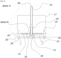
- the valve assembly 16 in detail in Figs. 2 and 3 comprises in the direction of fuel or combustion air flow: the suction diffuser 17 in the shape of de Laval nozzle with a variable, converging-diverging circular cross-section and intended for supplying combustion air; the fuel supply tube 23 for supplying fuel, extending through the centre of the suction diffuser 17 in the direction of the longitudinal axis 30 , leading to the combustion chamber 27 and ending with feed openings 39 ; the baffle 18 in the shape of a cone or a truncated cone, the base of which is oriented towards the end portion of the suction diffuser 17 ; the air curtain 19 arranged adjacent to the end portion of the suction diffuser 17 and to the base of the baffle 18 ; the support plate 22 arranged at a distance from the air curtain 19 in the direction of the longitudinal axis 30 ; the valve 20 arranged between the air curtain 19 and the support plate 22 ; and the insulating pad 21 arranged between the circular base 35 of the valve 20 and the support plate 22 .
- the air curtain 19 comprises the outer perforations 31 arranged along the outer circle 37 and the inner perforations 32 arranged along the inner circle 38 for supplying air between a part of the air curtain 19 adjacent to the end portion of the suction diffuser 17 and a part of the air curtain 19 adjacent to the base of the baffle 18 , i. e. in the area of the air curtain 19 not adjacent to the end of the suction diffuser 17 and to the base of the baffle 18 .
- the number of outer perforations 31 and the number of inner perforations 32 may be the same, e. g. twelve, with the outer perforations 31 having a larger diameter than the inner perforations 32 .
- the side of the support plate 22 adjacent to the air curtain 19 is conical or tapered towards the circumference of the support plate 22 .
- the valve 20 is in the shape of an n -polygon or a circle with the opening 34 for the fuel supply tube 23 in the centre and with the circular base 35 around the perimeter of the opening 34 .
- the valve 20 is divided from a circumferential part 36 towards the circular base 35 into n shutters 33 of an essentially trapezoidal shape, e. g. twelve shutters (the number corresponds to the number of outer and inner perforations 31 , 32 ).
- Each short base of said trapezoids is firmly or integrally connected to the circular base 35 and each long base of said trapezoids forms the circumferential part 36 of the valve 20.
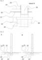
- the shutters 33 are bendable such that in the closed position of the valve 20 ( Fig. 4A ), the shutters 33 are adjacent to the air curtain 19 , thus overlapping the perforations 31 , 32 and blocking the air supply to the combustion chamber 27 and the expansion of flue gas into the suction diffuser 17 , and in the open position of the valve 20 ( Fig. 4B ), the shutters 33 are adjacent to the support plate 22 , leaving the perforations 31 , 32 open and allowing air to flow into the combustion chamber 27 .
- the principle of function of the pulse detonation engine 2 is as follows.
- the mixture of biogas and hydrogen is fed via the fuel supply tube 23 through the feed openings 39 to the combustion chamber 27 , where it is mixed with combustion air sucked by the suction diffuser 17 , along the baffle 18 , through the perforations 31 , 32 of the air curtain 19 and the open valve 20 abutted against the support plate 22 .
- the spark of the electric spark plug 28 ignites and detonates the mixture of fuel and air, leading to the rapid development of flue gasses at high temperature, pressure and velocity and to leaving the outlet tube 29 and the first flue gas output 4, further transforms enthalpy and kinetic energy of the flue gas into mechanical energy.
- valve 20 for supplying combustion air is also closed by being abutted against the air curtain 19 due to an underpressure in the combustion chamber 27 .
- a vacuum is created in the combustion chamber 27 , which opens the valve 20 by abutting it against the support plate 22 .
- the second example of an aspect of this invention is the biogas energy recovery unit, shown in [ Fig.6 ].
- the biogas energy recovery unit in [ Fig.6 ] comprises the pulse detonation engine 2 with a fuel inlet 1 (i. e. the fuel supply tube 23 ). the valve assembly 16 , the combustion chamber 27 and the outlet tube 29 with the first flue gas output 4 .
- the first flue gas output 4 is connected to the turbocharger 5 or the centripetal gas turbine 5 , which is further connected to the first power generator 6 .
- the turbocharger 5 or the centripetal gas turbine 5 is further at the second flue gas outlet 7 connected to the flue gas exchanger 8 , in which the flue gas is in thermal contact with the heat transfer medium of the closed Rankin-Clausius steam cycle.
- the flue gas is configured to leave the flue gas exchanger 8 by the third flue gas outlet 9 to the surroundings or for further processing.
- the Rankin-Clausius steam cycle comprises the flue gas exchanger 8 connected to the surface cooler 3 arranged in thermal contact with the outlet tube 29 of the pulse detonation engine 2 .
- the surface cooler 3 is further connected to the thrust steam turbine 11 which is connected to the second power generator 12 .
- the thrust steam turbine 11 is also connected to the flue gas exchanger 8 via the cooler 13 , the supply tank 14 and the feeding pump 10 .
- the cooler 13 is optionally connected to the accumulator 15 or to a heating system of a fermentation tank of a biogas station or to a biomass drying system.
- the principle of function of the biogas energy recovery unit is as follows. After the fuel enters the combustion chamber 27 of the pulse detonation engine 2 , the mixture of biogas and hydrogen in the required amount at an overpressure of approx. 0.8 bar is ignited together with the combustion air, and the flue gas arising from its detonation, the total energy of which corresponds to their enthalpy and the flow velocity, are routed through the outlet tube 29 with the first flue gas output 4 into the turbocharger 5 or the centripetal gas turbine 5 . Part of the heat generated by the combustion of flue gas and permeating through the walls of the outlet tube 29 of the pulsating detonation engine 2 is harvested by means of the surface cooler 3 .
- one part of the enthalpy and kinetic energy of the flue gas is transformed into electricity through the high-revolution first power generator 6 , and another part is, following the second flue gas output 7 from the turbocharger 5 or the centripetal gas turbine 5 , used for preheating circulation water in the flue gas exchanger 8 (economizer), which can be constructed as a flue gas pipe counter-current exchanger installed before the third flue gas output 9 into the surroundings, in order to reduce the outlet temperature of the flue gas and minimize losses during the transformation of the initial chemical energy of the biogas/hydrogen mixture.
- the flue gas exchanger 8 economizer
- Another circuit for a more efficient transformation of input energy of the biogas-hydrogen mixture in said unit is the closed Rankin-Clausius steam cycle, the working medium of which is water.
- the required water pressure in this circuit (3-4 bar) is provided by the feed pump 10 , after which the water is preheated in the flue gas exchanger 8 and evaporated in the surface cooler 3 . Then, water in the form of slightly overheated steam at a temperature corresponding to the pressure at the outlet of the feed pump 10 is introduced to the inlet of the thrust steam turbine 11 , in which its enthalpy is transformed partly into power in the second power generator 12 and partly into thermal energy, which is further used in the cooler 13 e. g.
- a boiler in a classic steam cycle is replaced by an assembly of the flue gas exchanger 8 and the surface heater 3 , and the entire connection of the unit actually corresponds to principles of a combined steam-gas cycle, which up to date is a system with the highest achieved total efficiency of input energy transformation.
- the third example of an aspect of this invention are the operational parameters of the biogas energy recovery unit, shown in Figs. 7-9 and Table 1.
- the thermal power of the unit increases due to higher calorific value of the combustion mixture (in Figs. 7-9 , the kW values for the accumulator 15 ).
- the above-described devices can be used in combination with existing biogas pipeline infrastructure and power and hot water networks in agricultural production, bio-waste or composting plants.
- the biogas energy recovery unit can be used in any technology where biogas is produced (biogas stations, waste water treatment plants, waste dumps) and it can be connected by pipeline to the corresponding device, while maintaining the overpressure of biogas at an input of about 0.8 bar (0.08 MPa).
Landscapes
- Engineering & Computer Science (AREA)
- Chemical & Material Sciences (AREA)
- Combustion & Propulsion (AREA)
- Mechanical Engineering (AREA)
- General Engineering & Computer Science (AREA)
- Fluidized-Bed Combustion And Resonant Combustion (AREA)
Description
- This invention relates to a pulse detonation engine for the combustion of a mixture of biogas and hydrogen, as well as to a biogas energy recovery unit for transforming the chemical energy of biogas into electrical and thermal energy.
- The growing need to streamline the production of any kind of energy supports the emergence of technologies working on principles using renewable sources and, at the same time, low-potential waste heat, which arises in the process of transforming their energy.
- A pulse detonation engine is one of the promising engines currently used as an aircraft drive, since its design allows intermittent permanent detonation and thus achieves significant flue gas thrust at the outlet. In a pulse detonation engine, the pressure of the emerging flue gas of the detonating fuel and their kinetic energy increases, thus increasing thermodynamical efficiency and thrust while being structurally and design-wise rather undemanding. Examples of known pulse detonation engines can be found in
US 2609660 A ,US 4222231 A andUS 5345758 A . - Until now, various fuels such as hydrogen (H2), a mixture of ethylene (C2H4) and propane (C3H8), or a mixture of ethylene and hydrogen have been tested for use in a pulse detonation engine, but due to the high demands of sustained provision of such energy sources, research has recently focused more on finding other sustainable energy sources while maintaining strict emission limits. Such fuel appears to be biogas, which is a renewable energy source and whose main components affecting calorific value are methane (CH4) and carbon dioxide (CO2).
- The use of biogas for the production of electricity and heat is widely known and mainly used in biogas plants in combustion engines that are part of cogeneration units, as well as the use of waste heat in cooling engines in which this biogas can be combusted.
- Hydrogen is also known to be much more reactive than methane itself, so this gas has been tested to enrich hydrocarbon fuels (propane, methane, LPG) to improve combustion performance. The parameters and characteristics of heat release from flue gas during the combustion of a mixture of biogas and hydrogen in diesel engines were also examined. At the same time, there is a lot of research in the area that confirms higher performance of biogas-powered diesel engines than those burning biogas-hydrogen mixtures.
- The effect of enrichment of methane, which is the main reactive component in biogas, with a certain amount of hydrogen in the combustion of this fuel mixture with air (CH4/H2/Air) on detonation properties is known in the areas of flame propagation characteristics, transition from deflation to detonation, rate of detonation, changes in flue gas pressure and temperature and various fuel/air ratios.
- To date, studies that would address the effect of biogas use in a pulse detonation engine are very limited and focus only on mathematical modelling, not resulting in a real engine design solution. The most important in this area is the mathematical study of Elhawara et al. (2020) entitled "Experimental study of using biogas in Pulse Detonation Engine with hydrogen enrichment" for combustion of a mixture of biogas and hydrogen with air at an initial pressure of 0.1 MPa and a temperature of 70 °C (343.15 K) and at a stoichiometric (equivalence) ratio fuel/air of 0.7 to 1.0 with different results in the field of size of detonation achieved by Mach's number, temperature and pressure of the generated flue gas. The study also comprises a pulse detonation engine in an experimental design, but without structural details.
- The effect of cell size of individual gases is also known, as is the result of an experiment that proves that biogas detonation is slower compared to propane for this reason. This means that it is very difficult to achieve detonation of pure biogas and in theory it may not be achieved at all due to the CO2 content, which is an important component of biogas, and at the same time, it is a strong anti-detonation element due to the size of its cells (i. e. the diameter of a CO2 detonation cell in the first layer of the shock wave).
- For the above reasons, the combustion of biogas in a pulse detonation engine creates the assumption of essentially using more reactive gas (e. g. H2) to enrich raw biogas. The effect of hydrogen biogas enrichment in a real working pulse detonation engine is still unknown and no research has been done in this field. In the current state of the art, pulse detonation engines for combustion of a mixture of biogas and hydrogen while maintaining permanent detonation are not known.
- Therefore, the aim of this invention is to provide a pulse detonation engine for combustion of a mixture of biogas and hydrogen with permanent detonation in a combustion chamber and with maximum flue gas rate at the outlet of the engine.
- The above-formulated aim is achieved in the first aspect of this invention by a pulse detonation engine according to
claim 1. - The pulse detonation engine comprises a valve assembly and a combustion chamber connected to the valve assembly, wherein the combustion chamber comprises a detonation initiation device (e. g. a spark plug) and a first flue gas outlet from the combustion chamber.
- The valve assembly comprises a suction diffuser for supplying combustion air, a fuel supply tube for supplying fuel, a baffle, an air curtain, a valve and a support plate of the valve.
- The suction diffuser is in the shape of de Laval nozzle with a variable, converging-diverging circular cross-section and extends along the direction of a longitudinal axis. The circular cross-section of the suction diffuser is narrower in a central portion thereof than in an end portion thereof facing the combustion chamber. The shape derived from de Laval nozzle ensures maximum flow velocity and thus the transport of necessary amount of air to the combustion chamber. To improve the efficiency of air expansion behind the central portion of the suction diffuser with the narrowest (critical) cross-section, an expanding end portion is connected thereto, the end diameter of which is essentially the same as the diameter of the air curtain and in which there is a further decrease in pressure and an increase in air velocity. Basic dimensions of the suction diffuser were chosen on the basis of the size (diameter) of the combustion chamber and in the range of known angles of expansion/narrowing of the nozzle in the range of 10-40° (e. g. 10°, 15°, 20°, 25°, 30°, 35° or 40°). Thus, the main dimensions of the suction diffuser can be of 30-40 mm in diameter at the inlet (e. g. 30, 32, 34, 36, 38 or 40 mm), 50-60 mm in diameter at the outlet (e. g. 50, 52, 54, 56, 58 or 60 mm) and a length of 40-60 mm (e. g. 40, 44, 48,52, 56 or 60 mm).
- The fuel supply tube extends through the centre of the suction diffuser in the direction of the longitudinal axis and leads to the combustion chamber. The expansion of flue gas into the fuel supply tube is prevented by the ratio of pressures in the fuel supply tube and at the outlet from the combustion chamber. While in the fuel supply tube, there is a permanent fuel overpressure of about 0.8-0.9 bar (0.08-0.09 MPa), which means an absolute pressure of about 1.8-1.9 bar (0.18-0.19 MPa), the outlet from the combustion chamber experiences a constant vacuum, i. e. an absolute pressure below 0.8-0.9 bar (0.08-0.09 MPa), due to its shape and flue gas expanding into the surroundings. The flue gasses therefore go through the route of the "least resistance" to the outlet tube of the combustion chamber, see below.
- The baffle for directing combustion air flow is arranged outside the fuel supply tube and co-axially relative to the longitudinal axis, wherein the baffle is in the shape of a cone or a truncated cone, the base of which is oriented towards the end portion of the suction diffuser. The baffle in the shape of a cone or a truncated cone aims to define an air channel and to ensure air supply towards the air curtain in an annular area defined on the inner side by a circle, which is smaller in diameter than the circle on which inner perforations in the air curtain are located and which corresponds to the diameter of the base of the baffle cone on the side facing the combustion chamber (e. g. 20, 22, 25 or 26 mm). On the other hand, for structural reasons, the upper (apex) diameter of the baffle cone (e. g. 8, 9, 10 or 11 mm) is greater than the diameter of the fuel supply tube, and at the same time the length of the baffle (e. g. 15, 17 or 18 mm) is determined by selecting its external angle (e. g. 17°, 20° or 22°). On the outside, the air channel is defined by the interior wall of the suction diffuser. With these parameters, it is possible to determine the necessary width of the air channel in its narrowest and widest cross-section in the direction of airflow. Thus, the width of the air gap at the narrowest point can be 8-11 mm, and the width of the air gap at the widest point can be 15-18 mm.
- The air curtain is arranged outside the fuel supply tube and adjacent to the end portion of the suction diffuser and to the base of the baffle such that it is arranged perpendicular to the longitudinal axis, wherein the air curtain comprises perforations for air supply between the part of the air curtain adjacent to the end portion of the suction diffuser and the part of the air curtain adjacent to the base of the baffle, i. e. in the area where the air curtain is not adjacent to the end portion of the suction diffuser and to the baffle base. There is an opening in the centre of the air curtain for the fuel supply tube.
- The support plate is arranged outside the fuel supply tube and at a distance from the air curtain in the direction of the longitudinal axis such that it is arranged perpendicular to the longitudinal axis, wherein the side of the support plate adjacent to the air curtain is of a concave shape or of a shape narrowing towards the circumference of the support plate. There is an opening in the centre of the support plate for the fuel supply tube.
- The valve is arranged outside the fuel supply tube and between the air curtain and the support plate such that it is arranged perpendicular to the longitudinal axis. The valve is in the shape of an n-polygon or a circle with an opening for the fuel supply tube in the centre and with a circular base around the perimeter of the opening. The valve is divided from a circumferential part towards the circular base into n shutters of an essentially trapezoidal shape. The material of the shutters requires a construction made of refractory steel at a minimum thickness, e. g. in the range of 0.10-0.60 mm, e. g. 0.10, 0.15, 0.20, 0.25, 0.30, 0.35, 0.40, 0.45, 0.50, 0.55 or 0.60 mm. Each short base of said trapezoids is firmly or integrally connected to the circular base and each long base of said trapezoids forms the circumferential part of the valve. The shutters of the valve are bendable such that in a closed position of the valve, the shutters are adjacent to the air curtain, thus overlapping the perforations and blocking air supply into the combustion chamber as well as expansion of flue gas into the suction diffuser, and in an open position of the valve, the shutters are adjacent to the support plate, thereby leaving the perforations open and allowing air to flow into the combustion chamber. Opening and closing of the valve (i. e. deflection of the shutters) is due to a decrease/ increase in relative pressure in the combustion chamber by about 0.1-0.2 bar (0.01-0.02 MPa).
- The combustion chamber is connected to the valve assembly in an axial direction in the direction of the longitudinal axis. The combustion chamber is designed for the combustion of an available amount of biogas, i. e. it is size-adapted to the expected flow rate of the fuel mixture (e. g. 0.05-0.15 or 0.09-0.12 mN 3/min) and the necessary air oxygenation to meet the minimum theoretical amount of combustion air. This also specifies the engine power. The volumetric flow rate of fuel, the amount of combustion air required and thus the amount of flue gas produced (e. g. 2.0-3.0 or 2.2-2.6 mN 3/min) determine the optimal size of the combustion chamber for perfect mixing of the fuel mixture with air before its actual ignition using a spark plug, for explosion and expansion into the outlet tube. Assuming that this amount of flue gas is held for 0.01 s in the combustion chamber, the combustion chamber size is about 0.2-0.6 m3, e. g. 0.2, 0.3, 0.4, 0.5 or 0.6 m3. The engine body must be made of refractory material due to high combustion temperatures.
- In a preferred embodiment, the perforations are arranged on the air curtain in two circular rows such that the outer perforations are arranged along an outer circle and the inner perforations are arranged along an inner circle at a distance from the outer circle. The outer perforations can have a larger diameter than the inner perforations. The larger diameter of the outer perforations at a greater distance from the centre of the air curtain ensures airflow in the end (expanding) portion of the suction diffuser. Adjacent outer and inner perforations can be arranged radially relative to the centre of the air curtain. In this arrangement, in the closed position of the valve, each shutter can then overlap one inner and one outer perforation.
- The diameter, number and distribution of perforations over the area of the air curtain, as well as the shape and number of valve shutters, are the result of experiments leading to ensuring stable engine operation. In theory, the number of perforations and their size may change, but with a given amount of combustion fuel (engine power), the area of perforations in the air curtain should be maintained, which area is the determining element for the transport of the necessary amount of combustion air. The diameters of the outer perforations of the air curtain can be 4-7 mm, e. g. 4.2 mm, 4.9 mm or 5.7 mm, and those of the inner perforations can be 2-4 mm, e. g. 2.5 mm, 3.2 mm or 3.8 mm, so that the flow cross-section of airflow is 390-415 mm2 in an exemplary engine, e. g. 394, 397, 400, 403, 407 or 411 mm2. It is possible to change the ratio of diameters of these perforations, but the total cross-section in tolerance of +/- 5 % should be maintained.
- In a particularly preferred embodiment, the engine comprises twelve outer perforations of the air curtain, twelve inner perforations of the air curtain and twelve shutters of the valve. It can be considered that the number of shutters could be less than the number of pairs of inner and outer perforations, and that one shutter would overlap more perforations at the same time, but this solution in turn does not allow the necessary deflection to be achieved due to the strength of the material. On the contrary, with a larger number of narrower shutters, one can observe destruction (break-off) in the area of the short trapezoidal base. Therefore, 12 shutters and 2x12 perforations are used, wherein one shutter closes/opens one pair of inner and outer perforations in the air curtain.
- In a preferred embodiment, the diameter of the valve and the diameter of the support plate are smaller than the diameter of the air curtain. Furthermore, the diameter of the support plate is smaller than the diameter of the valve. The outer diameters of the air curtain, valve and support plate are decreasing in the direction of airflow (e. g. D(air curtain) = 75 mm, D(valve) = 60 mm, D(support plate) = 56 mm), thus widening the flow air channel that is formed between the outer edge of the support plate and the interior side of a high-temperature graphite seal between the suction diffuser and the combustion chamber. On the end sharp inner edge of the flow air channel (i. e. the combination of a support plate and an open valve with a diameter slightly larger than the diameter of the support plate), there is turbulent airflow before entering the combustion chamber, which favourably affects mixing thereof with the fuel fed to the same point at the inlet to the combustion chamber from the feed openings of the inlet tube.
- In a preferred embodiment, the valve shutters are bendable at an angle in the range of 3-13°. The bending angle of the shutter is determined by the apex outer angle of the support plate and has been experimentally determined in the range of 3-13°, e. g. 3°, 4°, 5°, 6°, 7°, 8°, 9°, 10°, 11°, 12° or 13°. At a smaller apex angle of the support plate, i. e. with a higher deflection of the valve shutters, the shutters are more frequently broken off and, in particular, there is a large excess of air in the combustion chamber, which results in excessive cooling and non-detonation. At a larger apex angle, the shutters do not break, but the necessary amount of combustion air is not reached in the combustion chamber. The current arrangement thus ensures stable engine operation.
- In a preferred embodiment, an insulating pad is arranged between the circular base of the valve and the support plate and outside the fuel supply tube such that it is arranged perpendicular relative to the longitudinal axis. The insulating pad, preferably a mica pad, functions as thermal insulation to minimize heat transfer from the support plate to the circular base of the valve shutter, which are cyclically stressed by bending at this point.
- In a preferred embodiment, the fuel supply tube at an end leading to the combustion chamber comprises feed openings oriented essentially radially relative to the longitudinal axis. The fuel supply to the combustion chamber is performed by a system of openings at the end of the tube extending along the longitudinal axis of the engine and passing through the baffle, air curtain, valve and support plate and locked by means of two nuts located in about 1/3 of the length (on the apex diameter of the baffle) and at the end of the fuel supply tube, under the support plate. At the same time, the locking of the fuel supply tube serves to firmly connect the mentioned parts of the valve assembly.
- The fuel supply tube is blinded at the end leading to the combustion chamber and comprises 3 openings with a diameter of 1-3 mm, e. g. 1.2 mm, 1.5 mm or 2.1 mm, for supplying fuel, which are constructed through a locking nut radially from the centre of the fuel supply tube to its outer surface, thus functioning as simple nozzles. The fuel flowing through these nozzles is fed into the combustion chamber radially relative to the longitudinal axis of the fuel flow in the fuel supply tube and at the same time in a counter-current with the combustion air with which it mixes perfectly along the cross-section of the combustion chamber. After that, the mixture is ignited with the help of a spark plug (a detonation initiation means) and it detonates. After reaching the necessary temperature in the combustion chamber, the function of the spark plug is no longer needed, and the mixture self-ignites.
- In a preferred embodiment, the combustion chamber is connected to an outlet tube with the first flue gas outlet. The outlet tube ensures the propagation of shock wave after detonation of the mixture and obtaining the necessary flue gas velocity at the outlet. The diameter (d) and length (L) of the tube were chosen taking into account the width of the emerging detonation cells of CH4 and H2, with L/d being above 6-8, e. g. 6, 7, 8 or 10. At the end of the outlet tube, a nozzle is preferably installed for efficient expansion of the outlet flue gas, which is then brought by a semi-open connecting pipe system at high velocity and temperature to the input of a turbocharger or a centripetal gas turbine.
- The above-formulated aim is achieved in the second aspect of this invention by a biogas energy recovery unit, comprising the pulse detonation engine described herein, according to
claim 13. - In this unit, the pulse detonation engine at the first flue gas outlet is further connected to a turbocharger or a centripetal gas turbine, which turbocharger or centripetal gas turbine is connected to a first power generator.
- In a preferred embodiment, the turbocharger or the centripetal gas turbine is further connected via a second flue gas outlet to a flue gas exchanger, in which flue gas exchanger, the flue gas is in thermal contact with a heat transfer medium of a closed Rankin-Clausius steam cycle. The flue gas is configured to leave the flue gas exchanger by a third flue gas outlet.
- The closed Rankin-Clausius steam cycle may comprise the flue gas exchanger connected to a surface cooler arranged in thermal contact with the pulse detonation engine, preferably with the outlet tube of the pulse detonation engine. The surface cooler can also be connected to a thrust steam turbine, which is connected to a second power generator. The thrust steam turbine can further be connected via a supply tank and a feeding pump back to the flue gas exchanger.
- Between the thrust steam turbine and the supply tank, a cooler can be arranged in the closed Rankin-Clausius steam cycle, which is optionally connected to an accumulator or to a heating system of a fermentation tank of a biogas station or to a biomass drying system.
- The unit thus enables efficient use of biogas chemical energy by transforming it into mechanical, thermal and electrical energy. The unit uses technology of the pulse detonating engine combusting biogas mixed with hydrogen, in conjunction with the rotor of the radial turbocharger (or the centripetal gas turbine), and by connecting it to the thrust steam turbine using low-parameter water vapour enthalpies obtained by heating the water with heat when cooling the engine through the heat exchanger system. It is a highly efficient transformation of the chemical energy contained in the biofuel into mechanical energy of a rotating shaft of the turbocharger (or the centripetal gas turbine) in an operationally simple and reliable device.
- At the same time, part of the energy is released in the form of heat permeating through the boundaries of the system (thermal energy), and it is not lost, but used efficiently in the unit in order to increase the overall efficiency of the transformation of biogas chemical energy into electricity harvested at the terminals of the second power generator connected to the thrust steam turbine. At the end of this transformation, it is envisaged that the heat generated in the accumulator can be used purposefully, and the accumulator can be replaced by heat dissipation for heating of fermentation tanks in biogas production technology or used for drying biomass.
- The system of transformation of chemical energy contained in biogas into electrical and thermal energy is unique in the present invention not only due to the type of the engine used, but also due to the system of its connection within the unit, which thus benefits from minimising energy losses generated during individual transformations, thereby increasing the overall efficiency of power production.
- Last but not least, the advantage of the present unit according to the invention is the constructional, investment and operational simplicity.
- The above-formulated aim is achieved in the second aspect of this invention by a method of combustion of a mixture of biogas and hydrogen in the pulse detonation engine described herein or in the biogas energy recovery unit described herein. In this method, a fuel mixture comprising CH4, CO2 and H2 is fed into the combustion chamber of the pulse detonation engine, preferably in the amount of 44-60 % by volume of CH4, 20-30 % by volume of CO2 and 20-30 % by volume of H2, more preferably in the amount of 44-46 % by volume of CH4, 28-30 % by volume of CO2 and 24-26 % by volume of H2. The fuel mixture is fed into the combustion chamber with an overpressure of 0.8-0.9 bar (0.08-0.09 MPa).
- The pulsating detonation engine according to this invention is novel mainly in that it can combust gaseous fuel and biogas in particular. During development, various mixtures of gaseous fuels were combusted, ranging from 100 % hydrogen or methane, through a mixture of technical gases with biogas to pure biogas. It has been experimentally demonstrated that the addition of biogas has a negative effect on the combustion process (detonation) and its speed, in relation to the amount of CO2 contained therein. The engine operating with pure biogas had a heavier start and unstable combustion, accompanied by occasional engine failures. By adapting the engine design to the combustion conditions of the gaseous fuel mixture, the H2 content limit values (20-30 % depending on the composition of the biogas) have been preferably established, wherein the engine is able to reliably burn the mixture of biogas with hydrogen in stable operation.
- The pulse detonation engine is also unique in that it can process a mixture of fuel and emerging flue gas even at high temperatures, while ensuring the required compression of the fuel-air mixture, which is achieved in conventional piston internal combustion engines of conventional cogeneration units by changing the volume of the working space of the cylinder. Since this engine does not need to convert the sliding movement of a piston to the rotary movement of a shaft to obtain mechanical work to generate power in a generator, the engine works with high efficiency.
- The biogas energy recovery unit according to this invention is also unique in that the exhaust gases from the pulse detonation engine (flue gas) have a high temperature and can thus be used to produce steam for expansion on the thrust steam turbine to increase the overall efficiency of power production in the described unit.
- The underlying idea of the invention is further clarified in real working examples which are described using the accompanying drawings, where:
-
Fig.1
[Fig.1 ] shows a side sectional view of the pulse detonation engine; -
Fig.2
[Fig.2 ] shows detail A of [Fig.1 ]; -
Fig.3
[Fig.3 ] shows detail B of [Fig.2 ]; -
Fig.4
[Fig.4 ] shows a side sectional view of the pulse detonation engine with the valve in closed (A) and open (B) positions; -
Fig.5
[Fig.5 ] shows an exploded lateral and frontal view of the components of the pulse detonation engine; -
Fig.6
[Fig.6 ] schematically shows the connection of the biogas energy recovery unit; -
Fig.7
[Fig.7 ] shows the first example of process parameters of the biogas energy recovery unit (Test No. 1); -
Fig.8
[Fig.8 ] shows the second example of process parameters of the biogas energy recovery unit (Test No. 4); and -
Fig.9
[Fig.9 ] shows the third example of process parameters of the biogas energy recovery unit (Test No. 2). - The invention will be further clarified on the examples with reference to the relevant drawings.
- The first example of an aspect of this invention is the
pulse detonation engine 2 shown as a whole in [Fig.1 ] and in detail inFigs. 2-5 . - The
pulse detonation engine 2 in [Fig.1 ] comprises thevalve assembly 16 and thecombustion chamber 27 connected to thevalve assembly 16 axially along thelongitudinal axis 30. Thecombustion chamber 27 comprises a detonation initiation means (e. g. the spark plug 28), theoutlet tube 29 and the firstflue gas outlet 4 from theoutlet tube 29 of thecombustion chamber 27. The connection between thecombustion chamber 27 and thevalve assembly 16 is made using a centring and limitingring 24 and aclip 25 with agraphite seal 26. The centring and limitingring 24 with a recess for anair curtain 19 is important from a structural point of view to ensure a tight connection between thevalve assembly 16 and thecombustion chamber 27 after tightening theclip 25, which in a self-locking manner exerts the necessary contact force by slipping along the oblique surfaces of thesuction diffuser 17 and thecombustion chamber 27. In addition, the height of thering 24 defines the size of the air channel at the inlet to thecombustion chamber 27. Thegraphite seal 26 prevents heat transfer by conduction between thecombustion chamber 27 and the suction diffuser 17 (a heat bridge) and prevents local overheating of theair curtain 19. - The
valve assembly 16 in detail inFigs. 2 and3 comprises in the direction of fuel or combustion air flow: thesuction diffuser 17 in the shape of de Laval nozzle with a variable, converging-diverging circular cross-section and intended for supplying combustion air; thefuel supply tube 23 for supplying fuel, extending through the centre of thesuction diffuser 17 in the direction of thelongitudinal axis 30, leading to thecombustion chamber 27 and ending withfeed openings 39; thebaffle 18 in the shape of a cone or a truncated cone, the base of which is oriented towards the end portion of thesuction diffuser 17; theair curtain 19 arranged adjacent to the end portion of thesuction diffuser 17 and to the base of thebaffle 18; thesupport plate 22 arranged at a distance from theair curtain 19 in the direction of thelongitudinal axis 30 ; thevalve 20 arranged between theair curtain 19 and thesupport plate 22; and the insulatingpad 21 arranged between thecircular base 35 of thevalve 20 and thesupport plate 22. The above elements 17-23 are arranged axially along thelongitudinal axis 30 and the elements 18-22 are mounted on thefuel supply tube 23 from on its external side. The elements 19-22 are arranged perpendicular relative to thelongitudinal axis 30 - As shown in [
Fig.5 ], theair curtain 19 comprises theouter perforations 31 arranged along theouter circle 37 and theinner perforations 32 arranged along theinner circle 38 for supplying air between a part of theair curtain 19 adjacent to the end portion of thesuction diffuser 17 and a part of theair curtain 19 adjacent to the base of thebaffle 18, i. e. in the area of theair curtain 19 not adjacent to the end of thesuction diffuser 17 and to the base of thebaffle 18. In theair curtain 19, there is an opening in the centre for thefuel supply tube 23. The number ofouter perforations 31 and the number ofinner perforations 32 may be the same, e. g. twelve, with theouter perforations 31 having a larger diameter than theinner perforations 32. - As shown in [
Fig.4 ], the side of thesupport plate 22 adjacent to theair curtain 19 is conical or tapered towards the circumference of thesupport plate 22. There is an opening in the centre for thefuel supply tube 23. - As shown in [
Fig.5 ], thevalve 20 is in the shape of an n-polygon or a circle with theopening 34 for thefuel supply tube 23 in the centre and with thecircular base 35 around the perimeter of theopening 34. Thevalve 20 is divided from acircumferential part 36 towards thecircular base 35 inton shutters 33 of an essentially trapezoidal shape, e. g. twelve shutters (the number corresponds to the number of outer andinner perforations 31, 32). Each short base of said trapezoids is firmly or integrally connected to thecircular base 35 and each long base of said trapezoids forms thecircumferential part 36 of thevalve 20. - As shown in [
Fig.5 ], theshutters 33 are bendable such that in the closed position of the valve 20 (Fig. 4A ), theshutters 33 are adjacent to theair curtain 19, thus overlapping theperforations combustion chamber 27 and the expansion of flue gas into thesuction diffuser 17, and in the open position of the valve 20 (Fig. 4B ), theshutters 33 are adjacent to thesupport plate 22, leaving theperforations combustion chamber 27. - The principle of function of the
pulse detonation engine 2 is as follows. The mixture of biogas and hydrogen is fed via thefuel supply tube 23 through thefeed openings 39 to thecombustion chamber 27, where it is mixed with combustion air sucked by thesuction diffuser 17, along thebaffle 18, through theperforations air curtain 19 and theopen valve 20 abutted against thesupport plate 22. In thecombustion chamber 27, the spark of theelectric spark plug 28 ignites and detonates the mixture of fuel and air, leading to the rapid development of flue gasses at high temperature, pressure and velocity and to leaving theoutlet tube 29 and the firstflue gas output 4, further transforms enthalpy and kinetic energy of the flue gas into mechanical energy. When flue gas is expanded from thecombustion chamber 27, thevalve 20 for supplying combustion air is also closed by being abutted against theair curtain 19 due to an underpressure in thecombustion chamber 27. After leaving thecombustion chamber 27, a vacuum is created in thecombustion chamber 27, which opens thevalve 20 by abutting it against thesupport plate 22. - The second example of an aspect of this invention is the biogas energy recovery unit, shown in [
Fig.6 ]. - The biogas energy recovery unit in [
Fig.6 ] comprises thepulse detonation engine 2 with a fuel inlet 1 (i. e. the fuel supply tube 23). thevalve assembly 16, thecombustion chamber 27 and theoutlet tube 29 with the firstflue gas output 4. The firstflue gas output 4 is connected to the turbocharger 5 or the centripetal gas turbine 5, which is further connected to the first power generator 6. The turbocharger 5 or the centripetal gas turbine 5 is further at the secondflue gas outlet 7 connected to the flue gas exchanger 8, in which the flue gas is in thermal contact with the heat transfer medium of the closed Rankin-Clausius steam cycle. The flue gas is configured to leave the flue gas exchanger 8 by the third flue gas outlet 9 to the surroundings or for further processing. The Rankin-Clausius steam cycle comprises the flue gas exchanger 8 connected to thesurface cooler 3 arranged in thermal contact with theoutlet tube 29 of thepulse detonation engine 2. Thesurface cooler 3 is further connected to thethrust steam turbine 11 which is connected to thesecond power generator 12. Thethrust steam turbine 11 is also connected to the flue gas exchanger 8 via the cooler 13, thesupply tank 14 and the feedingpump 10. The cooler 13 is optionally connected to theaccumulator 15 or to a heating system of a fermentation tank of a biogas station or to a biomass drying system. - The principle of function of the biogas energy recovery unit is as follows. After the fuel enters the
combustion chamber 27 of thepulse detonation engine 2, the mixture of biogas and hydrogen in the required amount at an overpressure of approx. 0.8 bar is ignited together with the combustion air, and the flue gas arising from its detonation, the total energy of which corresponds to their enthalpy and the flow velocity, are routed through theoutlet tube 29 with the firstflue gas output 4 into the turbocharger 5 or the centripetal gas turbine 5. Part of the heat generated by the combustion of flue gas and permeating through the walls of theoutlet tube 29 of the pulsatingdetonation engine 2 is harvested by means of thesurface cooler 3. When passing through the turbocharger 5 or the centripetal gas turbine 5, one part of the enthalpy and kinetic energy of the flue gas is transformed into electricity through the high-revolution first power generator 6, and another part is, following the secondflue gas output 7 from the turbocharger 5 or the centripetal gas turbine 5, used for preheating circulation water in the flue gas exchanger 8 (economizer), which can be constructed as a flue gas pipe counter-current exchanger installed before the third flue gas output 9 into the surroundings, in order to reduce the outlet temperature of the flue gas and minimize losses during the transformation of the initial chemical energy of the biogas/hydrogen mixture. - Another circuit for a more efficient transformation of input energy of the biogas-hydrogen mixture in said unit is the closed Rankin-Clausius steam cycle, the working medium of which is water. The required water pressure in this circuit (3-4 bar) is provided by the
feed pump 10, after which the water is preheated in the flue gas exchanger 8 and evaporated in thesurface cooler 3. Then, water in the form of slightly overheated steam at a temperature corresponding to the pressure at the outlet of thefeed pump 10 is introduced to the inlet of thethrust steam turbine 11, in which its enthalpy is transformed partly into power in thesecond power generator 12 and partly into thermal energy, which is further used in the cooler 13 e. g. for heating a heat exchange medium for heating fermentation tanks in biogas station technology or for drying raw biomass. At the outlet of thethrust steam turbine 11, circulation already works with wet steam with a steam quality of about 60 % and its transformation into a saturated liquid is accompanied by heat dissipation in the cooler 13 and its use in theaccumulator 15. The saturated liquid, at the outlet pressure from thethrust steam turbine 11, then enters thesupply tank 14, from where it is transported, with the help of thefeed pump 10 while increasing the pressure, to the input of the flue gas exchanger 8 - Only an electric motor (or another drive) to power the
feed pump 10 needs to be powered by the power produced in the first orsecond generator 6, 12 as part of the unit's own consumption. Other transformations take place without the need for an external energy source. The necessary flue gas pressure before entering the turbocharger 5 (the centripetal gas turbine 5) is obtained as a result of detonation of the biogas/hydrogen mixture in thecombustion chamber 27 of thepulse detonation engine 2, thus replacing a compressor otherwise needed in conventional combustion turbine circulation. A boiler in a classic steam cycle is replaced by an assembly of the flue gas exchanger 8 and thesurface heater 3, and the entire connection of the unit actually corresponds to principles of a combined steam-gas cycle, which up to date is a system with the highest achieved total efficiency of input energy transformation. - The third example of an aspect of this invention are the operational parameters of the biogas energy recovery unit, shown in
Figs. 7-9 and Table 1. - The results of measurements of thermal-technical parameters during the conduct of operational tests demonstrate the possibility of achieving required power outputs depending on the amount of the input biogas, its composition and, in particular, the content of CO2. Depending on the composition of the input biogas, its treatment and enrichment with hydrogen in the range of 20-30 % by volume is performed. When igniting such enriched biogas, it is possible to obtain the required velocity of the output flue gas (105-115 m/s) at a high temperature (530-590 °C) (803.15-863.15 K), and the enthalpy and kinetic energy thus obtained can be further transformed for the production of electric power in the range of 8-10 kW with simultaneous gain of 4-8 kW of heat. The whole process takes place in the unit with thermal efficiency of the entire circulation in the range of 57-67 % and efficiency of electricity production in the range of 43-47 %.
- The results of measurements of thermal-technical parameters during the operation of the unit are given in Table 1 below and in the balance sheet diagrams of three different variants of values of the achieved outputs (
Figs. 7-9 ).Table 1. Parameters measured during engine operation. Test No. 1 2 3 4 Figure No. 7 9 - 8 Biogas fuel CH4 % by volume 60 45 49 44 CO 220 30 29 29 H 220 25 22 27 biogas overpressure bar 0.78 0.81 0.8 0.8 amount of biogas m3N/s 0.00145 0.00176 0.00172 0.00166 Surroundings ambient temperature ° C 13 5 5 temperature in the suction diffuser 179 9 9 atmospheric pressure Pa 98100 98900 98900 relative humidity % 26 75 75 Pulse detonation engine Surface temperatures: of the combustion chamber 27°C > 900 > 900 > 900 > 900 at the inlet to the outlet tube 29720 730 750 720 at the outlet from the outlet tube 29430 460 390 450 Flue gas Flue gas temperatures: inside the outlet tube 29°C 570 578 585 570 at the third flue gas outlet 9 into the surroundings 538 540 550 535 differential pressure Pa 3100 2900 3000 2900 flue gas pressure bar 1.5 1.5 1.5 1.5 velocity at first flue gas outlet 4 m/s 112.5 110.9 107.3 110.2 - It is clear from the above results that the quality of biogas combusted in terms of CH4 and CO2 content, which are the basic parameters for the amount of H2 mixed, has a major influence on the correct functioning of the pulse detonation engine and the whole unit. Reduced CH4 content, and thus higher CO2 content means the need to dispense a higher proportion of H2, thereby increasing the reactivity of the mixture, but reducing its calorific value. On the contrary, with a smaller proportion of H2, the calorific value of the burnt mixture increases. This is an explanation for the trend that with increasing CO2 content, the electrical power increases (in
Figs. 7-9 , the kW values for the first and second power generators 6, 12), and with increasing CH4 content, the thermal power of the unit increases due to higher calorific value of the combustion mixture (inFigs. 7-9 , the kW values for the accumulator 15). - The tests were performed to the extent of real composition of gases obtained from a biogas station, so that the lower limit of the CH4 content was 44 % and the upper 60 %. From other tests performed during engine development, it can be concluded that the engine has stable operation when burning biogas with a CO2 content in the range of 20-30 % with simultaneous mixing of H2 also in the range of 20-30 %. For the above reasons, it is clear that the ratio between H2, CO2 and CH4 affects the size of the electrical and thermal output achieved. However, the primary requirement in this example was to obtain the maximum value of electricity at the output of the unit, and therefore it can be concluded that to this end, it is optimal to burn less calorific biogas with a CH4 content up to 55 % and a CO2 content in the range of 35-40 %, which will be enriched with approx. 25 % of H2, thereby obtaining the resulting fuel mixture with a volume content of the main components: CH4 = 44-46 % by volume, CO2 = 28-30 % by volume, H2 = 24-26 % by volume.
- The above-described devices can be used in combination with existing biogas pipeline infrastructure and power and hot water networks in agricultural production, bio-waste or composting plants. The biogas energy recovery unit can be used in any technology where biogas is produced (biogas stations, waste water treatment plants, waste dumps) and it can be connected by pipeline to the corresponding device, while maintaining the overpressure of biogas at an input of about 0.8 bar (0.08 MPa).
-
- 1.
- fuel inlet
- 2.
- pulse detonation engine
- 3.
- surface cooler
- 4.
- first flue gas outlet
- 5.
- turbocharger or centripetal gas turbine
- 6.
- first power generator
- 7.
- second flue gas outlet
- 8.
- flue gas exchanger (or economizer)
- 9.
- third flue gas outlet
- 10.
- feeding pump
- 11.
- thrust steam turbine
- 12.
- second power generator
- 13.
- cooler (or mixing exchanger)
- 14.
- supply tank
- 15.
- accumulator (or heat exchanger)
- 16.
- valve assembly
- 17.
- suction diffuser
- 18.
- baffle
- 19.
- air curtain
- 20.
- valve
- 21.
- insulating pad
- 22.
- support plate
- 23.
- fuel supply tube
- 24.
- centring and limiting ring
- 25.
- clip
- 26.
- graphite seal
- 27.
- combustion chamber
- 28.
- spark plug
- 29.
- outlet tube
- 30.
- longitudinal axis
- 31.
- outer perforation of the
air curtain 19 - 32.
- inner perforation of the
air curtain 19 - 33.
- shutter of the
valve 20 - 34.
- opening of the
valve 20 - 35.
- circular base of the
valve 20 - 36.
- circumferential part of the
valve 20 - 37.
- outer circle of the
outer perforations 31 - 38.
- inner circle of the
inner perforations 32 - 39.
- feed opening of the
fuel supply tube 23
Claims (21)
- A pulse detonation engine (2) for the combustion of a mixture of biogas and hydrogen, comprising a valve assembly (16) and a combustion chamber (27) connected to the valve assembly (16), the combustion chamber (27) comprising a detonation initiation means and a first flue gas outlet (4), characterised in that the valve assembly (16) comprises:a. a suction diffuser (17) for supplying combustion air, wherein the suction diffuser (17) is in the shape of de Laval nozzle with a variable, converging-diverging circular cross-section and extends along the direction of a longitudinal axis (30), wherein the circular cross-section of the suction diffuser (17) is narrower in a central portion thereof than in an end portion thereof facing the combustion chamber (27);b. a fuel supply tube (23) for supplying fuel, extending through the centre of the suction diffuser (17) in the direction of the longitudinal axis (30) and leading to the combustion chamber (27);c. a baffle (18) arranged outside the fuel supply tube (23) and co-axially relative to the longitudinal axis (30), wherein the baffle (18) is in the shape of a cone or a truncated cone, the base of which is oriented towards the end portion of the suction diffuser (17);d. an air curtain (19) arranged outside the fuel supply tube (23) and adjacent to the end portion of the suction diffuser (17) and to the base of the baffle (18) such that it is arranged perpendicular to the longitudinal axis (30), wherein the air curtain comprises perforations (31, 32) for air supply;e. a support plate (22) arranged outside the fuel supply tube (23) and at a distance from the air curtain (19) in the direction of the longitudinal axis (30) such that it is arranged perpendicular to the longitudinal axis (30), wherein the side of the support plate (22) adjacent to the air curtain (19) is of a concave shape or of a shape narrowing towards the circumference of the support plate (22); andf. a valve (20) arranged outside the fuel supply tube (23) and between the air curtain (19) and the support plate (22) such that it is arranged perpendicular to the longitudinal axis (30), wherein the valve (20) is in the shape of an n-polygon or a circle with an opening (34) for the fuel supply tube (23) in the centre and with a circular base (35) around the perimeter of the opening (34), wherein the valve (20) is divided from a circumferential part (36) towards the circular base (35) into n shutters (33) of an essentially trapezoidal shape, each short base of said trapezoids being firmly or integrally connected to the circular base (35) and each long base of said trapezoids forming the circumferential part (36) of the valve (20), wherein the shutters (33) of the valve (20) are bendable such that in a closed position of the valve (20), the shutters (33) are adjacent to the air curtain (19), thus overlapping the perforations (31, 32) and blocking air supply into the combustion chamber (27) as well as expansion of flue gases into the suction diffuser (17), and in an open position of the valve (20), the shutters (33) are adjacent to the support plate (22), thereby leaving the perforations (31, 32) open and allowing air to flow into the combustion chamber (27).
- The pulse detonation engine (2) according to claim 1, wherein the perforations (31, 32) are arranged on the air curtain (19) in two circular rows such that the outer perforations (31) are arranged along an outer circle (37) and the inner perforations (32) are arranged along an inner circle (38) at a distance from the outer circle (37).
- The pulse detonation engine (2) according to claim 2, wherein the outer perforations (31) have a larger diameter than the inner perforations (32).
- The pulse detonation engine (2) according to claim 2 or 3, wherein adjacent outer and inner perforations (31, 32) are arranged radially relative to the centre of the air curtain (19).
- The pulse detonation engine (2) according to any of claims 2 to 4, wherein each shutter (33) overlaps one inner and one outer perforation (31, 32) in the closed position of the valve (20).
- The pulse detonation engine (2) according to any of the previous claims, wherein it comprises twelve outer perforations (31) of the air curtain (19), twelve inner perforations (32) of the air curtain (19) and twelve shutters (33) of the valve (20).
- The pulse detonation engine (2) according to any of the previous claims, wherein the diameter of the valve (20) and the diameter of the support plate (22) are smaller than the diameter of the air curtain (19).
- The pulse detonation engine (2) according to claim 7, wherein the diameter of the support plate (22) is smaller than the diameter of the valve (20).
- The pulse detonation engine (2) according to any of the previous claims, wherein the shutters (33) of the valve (20) are bendable at an angle in the range of 3-13°.
- The pulse detonation engine (2) according to any of the previous claims, wherein between the circular base (35) of the valve (20) and the support plate (22), an insulating pad (21) is arranged outside the fuel supply tube (23) such that it is arranged perpendicular relative to the longitudinal axis (30).
- The pulse detonation engine (2) according to any of the previous claims, wherein the fuel supply tube (23) at an end leading to the combustion chamber (27) comprises feed openings (39) oriented essentially radially relative to the longitudinal axis (30).
- The pulse detonation engine (2) according to any of the previous claims, wherein the combustion chamber (27) is connected to an outlet tube (29) with the first flue gas outlet (4).
- A biogas energy recovery unit, comprising the pulse detonation engine (2) according to any of the previous claims, characterised in that the pulse detonation engine (2) is further connected via the first flue gas outlet (4) to a turbocharger (5) or a centripetal gas turbine (5), which turbocharger (5) or centripetal gas turbine (5) is connected to a first power generator (6).
- The unit according to claim 13, wherein the turbocharger (5) or the centripetal gas turbine (5) is further connected via a second flue gas outlet (7) to a flue gas exchanger (8), wherein in the flue gas exchanger (8), the flue gas is in thermal contact with a heat transfer medium of a closed Rankin-Clausius steam cycle, wherein the flue gas is configured to leave the flue gas exchanger (8) by a third flue gas outlet (9).
- The unit according to claim 14, wherein the closed Rankin-Clausius steam cycle comprises the flue gas exchanger (8) connected to a surface cooler (3) arranged in thermal contact with the pulse detonation engine (2), wherein the surface cooler (3) is further connected to a thrust steam turbine (11) connected to a second power generator (12), wherein the thrust steam turbine (11) is further connected via a supply tank (14) and a feeding pump (10) to the flue gas exchanger (8).
- The unit according to claim 15, wherein between the thrust steam turbine (11) and the supply tank (14), a cooler (13) is arranged in the closed Rankin-Clausius steam cycle, which is optionally connected to an accumulator (15) or to a heating system of a fermentation tank of a biogas station or to a biomass drying system.
- The unit according to any of claims 13 to 16, wherein the surface cooler (3) is arranged in thermal contact with the outlet tube (29) of the pulse detonation engine (2).
- A method of combustion of a mixture of biogas and hydrogen in the pulse detonation engine (2) according to any of claims 1 to 12 or in the biogas energy recovery unit according to any of claims 13 to 17, characterised in that a fuel mixture comprising CH4, CO2 and H2 is fed into the combustion chamber (27).
- The method according to claim 18, wherein a fuel mixture comprising 44-60 % by volume of CH4, 20-30 % by volume of CO2 and 20-30 % by volume of H2 is fed into the combustion chamber (27).
- The method according to any of claims 18 to 19, wherein a fuel mixture comprising 44-46 % by volume of CH4, 28-30 % by volume of CO2 and 24-26 % by volume of H2 is fed into the combustion chamber (27).
- The method according to any of claims 18 to 20, wherein the fuel mixture is fed into the combustion chamber (27) with an overpressure of 0.8-0.9 bar (0.08-0.09 MPa).
Applications Claiming Priority (1)
| Application Number | Priority Date | Filing Date | Title |
|---|---|---|---|
| PCT/CZ2021/050064 WO2022174844A1 (en) | 2021-06-18 | 2021-06-18 | A pulse detonation engine and a biogas energy recovery unit |
Publications (2)
| Publication Number | Publication Date |
|---|---|
| EP4103828A1 EP4103828A1 (en) | 2022-12-21 |
| EP4103828B1 true EP4103828B1 (en) | 2023-04-26 |
Family
ID=77021015
Family Applications (1)
| Application Number | Title | Priority Date | Filing Date |
|---|---|---|---|
| EP21745230.9A Active EP4103828B1 (en) | 2021-06-18 | 2021-06-18 | A pulse detonation engine and a biogas energy recovery unit |
Country Status (2)
| Country | Link |
|---|---|
| EP (1) | EP4103828B1 (en) |
| WO (1) | WO2022174844A1 (en) |
Family Cites Families (3)
| Publication number | Priority date | Publication date | Assignee | Title |
|---|---|---|---|---|
| US2609660A (en) * | 1946-02-25 | 1952-09-09 | Tenney | Resonating pulse jet engine |
| US4222231A (en) * | 1978-07-20 | 1980-09-16 | Linn Wallace L | Engine |
| US5345758A (en) * | 1993-04-14 | 1994-09-13 | Adroit Systems, Inc. | Rotary valve multiple combustor pulse detonation engine |
-
2021
- 2021-06-18 EP EP21745230.9A patent/EP4103828B1/en active Active
- 2021-06-18 WO PCT/CZ2021/050064 patent/WO2022174844A1/en not_active Ceased
Also Published As
| Publication number | Publication date |
|---|---|
| WO2022174844A1 (en) | 2022-08-25 |
| EP4103828A1 (en) | 2022-12-21 |
Similar Documents
| Publication | Publication Date | Title |
|---|---|---|
| KR102065582B1 (en) | Fuel injection device for gas turbine, fuelnozzle and gas turbinehaving it | |
| US20030136398A1 (en) | Combustion system for hybrid solar fossil fuel receiver | |
| RU2642715C2 (en) | Two-stage vacuum burner | |
| CA2876065A1 (en) | Gaseous fuel burner with high energy and combustion efficiency, low pollutant emission and increased heat transfer | |
| JP2001241663A (en) | Multi-stage multi-plane combustion system for gas turbine engine | |
| US12253259B2 (en) | Combustion systems including heat modules, and associated devices and methods | |
| US12038178B2 (en) | Micro-mixer with multi-stage fuel supply and gas turbine including same | |
| CN102844622A (en) | Multi-fuel combustion system | |
| CN102226449B (en) | Working medium heating device of gas turbine solar power generation system | |
| US20120308943A1 (en) | Energy-saving method for gas combustion and burner thereof | |
| US12049844B2 (en) | Micro-mixer module and combustor having the same | |
| US20180179961A1 (en) | Turbine engine assembly and method of operating | |
| US12146661B2 (en) | Combustor nozzle, combustor, and gas turbine including the same | |
| EP4103828B1 (en) | A pulse detonation engine and a biogas energy recovery unit | |
| US11846417B2 (en) | Micro-mixer bundle assembly, and combustor and gas turbine having same | |
| KR102047369B1 (en) | Fuel nozzle, combustor and gas turbine having the same | |
| CN108779918A (en) | For generate energy, particularly electric energy turbine, especially include storage heater the turbine with thermodynamic cycle combustion chamber | |
| CN114151804B (en) | Exhaust gas treatment burners for power generation systems | |
| US11959642B2 (en) | Micro-mixer and gas turbine including same | |
| JP3936160B2 (en) | Gas turbine power generator and mixed gas combustion apparatus used therefor | |
| CN223612437U (en) | An integrated thermal component for burners and evaporators | |
| EP4567331A1 (en) | Combustor nozzle, combustor, and gas turbine including same | |
| EP4571193A1 (en) | Combustor nozzle, combustor, and gas turbine including same | |
| EP4707563A1 (en) | Duct burner and gas turbine system | |
| CN119844769A (en) | Preheating type efficient gas stove |
Legal Events
| Date | Code | Title | Description |
|---|---|---|---|
| STAA | Information on the status of an ep patent application or granted ep patent |
Free format text: STATUS: UNKNOWN |
|
| STAA | Information on the status of an ep patent application or granted ep patent |
Free format text: STATUS: THE INTERNATIONAL PUBLICATION HAS BEEN MADE |
|
| PUAI | Public reference made under article 153(3) epc to a published international application that has entered the european phase |
Free format text: ORIGINAL CODE: 0009012 |
|
| STAA | Information on the status of an ep patent application or granted ep patent |
Free format text: STATUS: REQUEST FOR EXAMINATION WAS MADE |
|
| 17P | Request for examination filed |
Effective date: 20220905 |
|
| AK | Designated contracting states |
Kind code of ref document: A1 Designated state(s): AL AT BE BG CH CY CZ DE DK EE ES FI FR GB GR HR HU IE IS IT LI LT LU LV MC MK MT NL NO PL PT RO RS SE SI SK SM TR |
|
| GRAP | Despatch of communication of intention to grant a patent |
Free format text: ORIGINAL CODE: EPIDOSNIGR1 |
|
| STAA | Information on the status of an ep patent application or granted ep patent |
Free format text: STATUS: GRANT OF PATENT IS INTENDED |
|
| GRAS | Grant fee paid |
Free format text: ORIGINAL CODE: EPIDOSNIGR3 |
|
| INTG | Intention to grant announced |
Effective date: 20230126 |
|
| GRAA | (expected) grant |
Free format text: ORIGINAL CODE: 0009210 |
|
| STAA | Information on the status of an ep patent application or granted ep patent |
Free format text: STATUS: THE PATENT HAS BEEN GRANTED |
|
| RIN1 | Information on inventor provided before grant (corrected) |
Inventor name: RUSIN, JIRI Inventor name: VYTISK, TOMAS Inventor name: RIEMEL, DAVID Inventor name: MADRY, FERDINAND |
|
| DAV | Request for validation of the european patent (deleted) | ||
| DAX | Request for extension of the european patent (deleted) | ||
| AK | Designated contracting states |
Kind code of ref document: B1 Designated state(s): AL AT BE BG CH CY CZ DE DK EE ES FI FR GB GR HR HU IE IS IT LI LT LU LV MC MK MT NL NO PL PT RO RS SE SI SK SM TR |
|
| REG | Reference to a national code |
Ref country code: GB Ref legal event code: FG4D |
|
| REG | Reference to a national code |
Ref country code: CH Ref legal event code: EP |
|
| REG | Reference to a national code |
Ref country code: DE Ref legal event code: R096 Ref document number: 602021002086 Country of ref document: DE |
|
| REG | Reference to a national code |
Ref country code: AT Ref legal event code: REF Ref document number: 1562975 Country of ref document: AT Kind code of ref document: T Effective date: 20230515 |
|
| REG | Reference to a national code |
Ref country code: IE Ref legal event code: FG4D |
|
| P01 | Opt-out of the competence of the unified patent court (upc) registered |
Effective date: 20230601 |
|
| REG | Reference to a national code |
Ref country code: LT Ref legal event code: MG9D |
|
| REG | Reference to a national code |
Ref country code: NL Ref legal event code: MP Effective date: 20230426 |
|
| PG25 | Lapsed in a contracting state [announced via postgrant information from national office to epo] |
Ref country code: NL Free format text: LAPSE BECAUSE OF FAILURE TO SUBMIT A TRANSLATION OF THE DESCRIPTION OR TO PAY THE FEE WITHIN THE PRESCRIBED TIME-LIMIT Effective date: 20230426 |
|
| PG25 | Lapsed in a contracting state [announced via postgrant information from national office to epo] |
Ref country code: SE Free format text: LAPSE BECAUSE OF FAILURE TO SUBMIT A TRANSLATION OF THE DESCRIPTION OR TO PAY THE FEE WITHIN THE PRESCRIBED TIME-LIMIT Effective date: 20230426 Ref country code: PT Free format text: LAPSE BECAUSE OF FAILURE TO SUBMIT A TRANSLATION OF THE DESCRIPTION OR TO PAY THE FEE WITHIN THE PRESCRIBED TIME-LIMIT Effective date: 20230828 Ref country code: NO Free format text: LAPSE BECAUSE OF FAILURE TO SUBMIT A TRANSLATION OF THE DESCRIPTION OR TO PAY THE FEE WITHIN THE PRESCRIBED TIME-LIMIT Effective date: 20230726 Ref country code: ES Free format text: LAPSE BECAUSE OF FAILURE TO SUBMIT A TRANSLATION OF THE DESCRIPTION OR TO PAY THE FEE WITHIN THE PRESCRIBED TIME-LIMIT Effective date: 20230426 |
|
| PGFP | Annual fee paid to national office [announced via postgrant information from national office to epo] |
Ref country code: IE Payment date: 20230927 Year of fee payment: 3 |
|
| PG25 | Lapsed in a contracting state [announced via postgrant information from national office to epo] |
Ref country code: RS Free format text: LAPSE BECAUSE OF FAILURE TO SUBMIT A TRANSLATION OF THE DESCRIPTION OR TO PAY THE FEE WITHIN THE PRESCRIBED TIME-LIMIT Effective date: 20230426 Ref country code: PL Free format text: LAPSE BECAUSE OF FAILURE TO SUBMIT A TRANSLATION OF THE DESCRIPTION OR TO PAY THE FEE WITHIN THE PRESCRIBED TIME-LIMIT Effective date: 20230426 Ref country code: LV Free format text: LAPSE BECAUSE OF FAILURE TO SUBMIT A TRANSLATION OF THE DESCRIPTION OR TO PAY THE FEE WITHIN THE PRESCRIBED TIME-LIMIT Effective date: 20230426 Ref country code: LT Free format text: LAPSE BECAUSE OF FAILURE TO SUBMIT A TRANSLATION OF THE DESCRIPTION OR TO PAY THE FEE WITHIN THE PRESCRIBED TIME-LIMIT Effective date: 20230426 Ref country code: IS Free format text: LAPSE BECAUSE OF FAILURE TO SUBMIT A TRANSLATION OF THE DESCRIPTION OR TO PAY THE FEE WITHIN THE PRESCRIBED TIME-LIMIT Effective date: 20230826 Ref country code: HR Free format text: LAPSE BECAUSE OF FAILURE TO SUBMIT A TRANSLATION OF THE DESCRIPTION OR TO PAY THE FEE WITHIN THE PRESCRIBED TIME-LIMIT Effective date: 20230426 Ref country code: GR Free format text: LAPSE BECAUSE OF FAILURE TO SUBMIT A TRANSLATION OF THE DESCRIPTION OR TO PAY THE FEE WITHIN THE PRESCRIBED TIME-LIMIT Effective date: 20230727 |
|
| PG25 | Lapsed in a contracting state [announced via postgrant information from national office to epo] |
Ref country code: FI Free format text: LAPSE BECAUSE OF FAILURE TO SUBMIT A TRANSLATION OF THE DESCRIPTION OR TO PAY THE FEE WITHIN THE PRESCRIBED TIME-LIMIT Effective date: 20230426 |
|
| PG25 | Lapsed in a contracting state [announced via postgrant information from national office to epo] |
Ref country code: SK Free format text: LAPSE BECAUSE OF FAILURE TO SUBMIT A TRANSLATION OF THE DESCRIPTION OR TO PAY THE FEE WITHIN THE PRESCRIBED TIME-LIMIT Effective date: 20230426 |
|
| PG25 | Lapsed in a contracting state [announced via postgrant information from national office to epo] |
Ref country code: MC Free format text: LAPSE BECAUSE OF FAILURE TO SUBMIT A TRANSLATION OF THE DESCRIPTION OR TO PAY THE FEE WITHIN THE PRESCRIBED TIME-LIMIT Effective date: 20230426 |
|
| REG | Reference to a national code |
Ref country code: DE Ref legal event code: R097 Ref document number: 602021002086 Country of ref document: DE |
|
| PG25 | Lapsed in a contracting state [announced via postgrant information from national office to epo] |
Ref country code: SM Free format text: LAPSE BECAUSE OF FAILURE TO SUBMIT A TRANSLATION OF THE DESCRIPTION OR TO PAY THE FEE WITHIN THE PRESCRIBED TIME-LIMIT Effective date: 20230426 Ref country code: SK Free format text: LAPSE BECAUSE OF FAILURE TO SUBMIT A TRANSLATION OF THE DESCRIPTION OR TO PAY THE FEE WITHIN THE PRESCRIBED TIME-LIMIT Effective date: 20230426 Ref country code: RO Free format text: LAPSE BECAUSE OF FAILURE TO SUBMIT A TRANSLATION OF THE DESCRIPTION OR TO PAY THE FEE WITHIN THE PRESCRIBED TIME-LIMIT Effective date: 20230426 Ref country code: MC Free format text: LAPSE BECAUSE OF FAILURE TO SUBMIT A TRANSLATION OF THE DESCRIPTION OR TO PAY THE FEE WITHIN THE PRESCRIBED TIME-LIMIT Effective date: 20230426 Ref country code: EE Free format text: LAPSE BECAUSE OF FAILURE TO SUBMIT A TRANSLATION OF THE DESCRIPTION OR TO PAY THE FEE WITHIN THE PRESCRIBED TIME-LIMIT Effective date: 20230426 Ref country code: DK Free format text: LAPSE BECAUSE OF FAILURE TO SUBMIT A TRANSLATION OF THE DESCRIPTION OR TO PAY THE FEE WITHIN THE PRESCRIBED TIME-LIMIT Effective date: 20230426 |
|
| REG | Reference to a national code |
Ref country code: BE Ref legal event code: MM Effective date: 20230630 |
|
| PG25 | Lapsed in a contracting state [announced via postgrant information from national office to epo] |
Ref country code: LU Free format text: LAPSE BECAUSE OF NON-PAYMENT OF DUE FEES Effective date: 20230618 |
|
| PLBE | No opposition filed within time limit |
Free format text: ORIGINAL CODE: 0009261 |
|
| STAA | Information on the status of an ep patent application or granted ep patent |
Free format text: STATUS: NO OPPOSITION FILED WITHIN TIME LIMIT |
|
| PG25 | Lapsed in a contracting state [announced via postgrant information from national office to epo] |
Ref country code: LU Free format text: LAPSE BECAUSE OF NON-PAYMENT OF DUE FEES Effective date: 20230618 |
|
| 26N | No opposition filed |
Effective date: 20240129 |
|
| PG25 | Lapsed in a contracting state [announced via postgrant information from national office to epo] |
Ref country code: SI Free format text: LAPSE BECAUSE OF FAILURE TO SUBMIT A TRANSLATION OF THE DESCRIPTION OR TO PAY THE FEE WITHIN THE PRESCRIBED TIME-LIMIT Effective date: 20230426 |
|
| PG25 | Lapsed in a contracting state [announced via postgrant information from national office to epo] |
Ref country code: SI Free format text: LAPSE BECAUSE OF FAILURE TO SUBMIT A TRANSLATION OF THE DESCRIPTION OR TO PAY THE FEE WITHIN THE PRESCRIBED TIME-LIMIT Effective date: 20230426 Ref country code: IT Free format text: LAPSE BECAUSE OF FAILURE TO SUBMIT A TRANSLATION OF THE DESCRIPTION OR TO PAY THE FEE WITHIN THE PRESCRIBED TIME-LIMIT Effective date: 20230426 Ref country code: FR Free format text: LAPSE BECAUSE OF NON-PAYMENT OF DUE FEES Effective date: 20230626 Ref country code: BE Free format text: LAPSE BECAUSE OF NON-PAYMENT OF DUE FEES Effective date: 20230630 |
|
| PG25 | Lapsed in a contracting state [announced via postgrant information from national office to epo] |
Ref country code: BG Free format text: LAPSE BECAUSE OF FAILURE TO SUBMIT A TRANSLATION OF THE DESCRIPTION OR TO PAY THE FEE WITHIN THE PRESCRIBED TIME-LIMIT Effective date: 20230426 |
|
| PG25 | Lapsed in a contracting state [announced via postgrant information from national office to epo] |
Ref country code: BG Free format text: LAPSE BECAUSE OF FAILURE TO SUBMIT A TRANSLATION OF THE DESCRIPTION OR TO PAY THE FEE WITHIN THE PRESCRIBED TIME-LIMIT Effective date: 20230426 |
|
| REG | Reference to a national code |
Ref country code: CH Ref legal event code: PL |
|
| PG25 | Lapsed in a contracting state [announced via postgrant information from national office to epo] |
Ref country code: IE Free format text: LAPSE BECAUSE OF NON-PAYMENT OF DUE FEES Effective date: 20240618 |
|
| PG25 | Lapsed in a contracting state [announced via postgrant information from national office to epo] |
Ref country code: CH Free format text: LAPSE BECAUSE OF NON-PAYMENT OF DUE FEES Effective date: 20240630 |
|
| PGFP | Annual fee paid to national office [announced via postgrant information from national office to epo] |
Ref country code: DE Payment date: 20250428 Year of fee payment: 5 |
|
| PGFP | Annual fee paid to national office [announced via postgrant information from national office to epo] |
Ref country code: AT Payment date: 20250721 Year of fee payment: 5 |
|
| PG25 | Lapsed in a contracting state [announced via postgrant information from national office to epo] |
Ref country code: CY Free format text: LAPSE BECAUSE OF FAILURE TO SUBMIT A TRANSLATION OF THE DESCRIPTION OR TO PAY THE FEE WITHIN THE PRESCRIBED TIME-LIMIT; INVALID AB INITIO Effective date: 20210618 |
|
| PGFP | Annual fee paid to national office [announced via postgrant information from national office to epo] |
Ref country code: CZ Payment date: 20250425 Year of fee payment: 5 |
|
| PG25 | Lapsed in a contracting state [announced via postgrant information from national office to epo] |
Ref country code: HU Free format text: LAPSE BECAUSE OF FAILURE TO SUBMIT A TRANSLATION OF THE DESCRIPTION OR TO PAY THE FEE WITHIN THE PRESCRIBED TIME-LIMIT; INVALID AB INITIO Effective date: 20210618 |
|
| REG | Reference to a national code |
Ref country code: AT Ref legal event code: UEP Ref document number: 1562975 Country of ref document: AT Kind code of ref document: T Effective date: 20230426 |
|
| PG25 | Lapsed in a contracting state [announced via postgrant information from national office to epo] |
Ref country code: TR Free format text: LAPSE BECAUSE OF FAILURE TO SUBMIT A TRANSLATION OF THE DESCRIPTION OR TO PAY THE FEE WITHIN THE PRESCRIBED TIME-LIMIT Effective date: 20230426 |
|
| GBPC | Gb: european patent ceased through non-payment of renewal fee |
Effective date: 20250618 |
|
| PG25 | Lapsed in a contracting state [announced via postgrant information from national office to epo] |
Ref country code: GB Free format text: LAPSE BECAUSE OF NON-PAYMENT OF DUE FEES Effective date: 20250618 |