EP4102884A1 - Handling new radio (nr) traffic configured with non-integer periodicity - Google Patents
Handling new radio (nr) traffic configured with non-integer periodicity Download PDFInfo
- Publication number
- EP4102884A1 EP4102884A1 EP22177622.2A EP22177622A EP4102884A1 EP 4102884 A1 EP4102884 A1 EP 4102884A1 EP 22177622 A EP22177622 A EP 22177622A EP 4102884 A1 EP4102884 A1 EP 4102884A1
- Authority
- EP
- European Patent Office
- Prior art keywords
- csi
- integer
- periodicity
- configuration information
- processor
- Prior art date
- Legal status (The legal status is an assumption and is not a legal conclusion. Google has not performed a legal analysis and makes no representation as to the accuracy of the status listed.)
- Granted
Links
Images





Classifications
-
- H—ELECTRICITY
- H04—ELECTRIC COMMUNICATION TECHNIQUE
- H04W—WIRELESS COMMUNICATION NETWORKS
- H04W24/00—Supervisory, monitoring or testing arrangements
- H04W24/10—Scheduling measurement reports ; Arrangements for measurement reports
-
- H—ELECTRICITY
- H04—ELECTRIC COMMUNICATION TECHNIQUE
- H04W—WIRELESS COMMUNICATION NETWORKS
- H04W24/00—Supervisory, monitoring or testing arrangements
- H04W24/08—Testing, supervising or monitoring using real traffic
-
- H—ELECTRICITY
- H04—ELECTRIC COMMUNICATION TECHNIQUE
- H04W—WIRELESS COMMUNICATION NETWORKS
- H04W76/00—Connection management
- H04W76/20—Manipulation of established connections
- H04W76/28—Discontinuous transmission [DTX]; Discontinuous reception [DRX]
Definitions
- NR new radio
- augmented reality (AR) and virtual reality (VR) applications may have traffic that is not supported by any NR unit of time.
- AR augmented reality
- VR virtual reality
- the existing solution to address this type of timing issue is the over-provisioning of resources.
- this is an inefficient use of network resources and may cause a user equipment (UE) to experience a power drain. Accordingly, there is a need for enhancements for managing NR traffic that does not match NR's default timing.
- Some exemplary embodiments are related to a processor of a user equipment (UE) configured to perform operations.
- the operations include receiving channel state information (CSI) configuration information corresponding to downlink new radio (NR) traffic with non-integer periodicity, wherein the CSI configuration information includes one of CSI measurement configuration information, CSI reporting configuration information or CSI measurement configuration information and CSI reporting configuration information, receiving CSI measurement resources and reporting CSI feedback to a network.
- CSI channel state information
- NR downlink new radio
- exemplary embodiments are related to a processor of a base station configured to perform operations.
- the operations include transmitting channel state information (CSI) configuration information corresponding to downlink new radio (NR) traffic with non-integer periodicity to a user equipment (UE), wherein the CSI configuration information includes one or more of CSI measurement configuration information and CSI reporting configuration information, transmitting CSI measurement resources and receiving CSI feedback from the UE.
- CSI channel state information
- NR downlink new radio
- UE user equipment
- Still further exemplary embodiments are related to a processor of a user equipment (UE) configured to perform operations.
- the operations include receiving connected discontinuous reception (cDRX) configuration information for downlink new radio (NR) traffic with non-integer periodicity, implementing a cDRX cycle based on the configuration information and receiving physical downlink control channel (PDCCH) during an onDuration of the cDRX cycle.
- cDRX connected discontinuous reception
- NR downlink new radio
- PDCCH physical downlink control channel
- Additional exemplary embodiments are related to a processor of a base station configured to perform operations.
- the operations include transmitting connected discontinuous reception (cDRX) configuration information for downlink new radio (NR) traffic with non-integer periodicity to a user equipment (UE) and transmitting physical downlink control channel (PDCCH) during an onDuration of a cDRX cycle implemented by the UE.
- cDRX connected discontinuous reception
- NR downlink new radio
- PDCCH physical downlink control channel
- the exemplary embodiments may be further understood with reference to the following description and the related appended drawings, wherein like elements are provided with the same reference numerals.
- the exemplary embodiments introduce techniques for handling traffic that may not match integer multiples of the units of time supported in new radio (NR).
- the exemplary embodiments relate to channel state information (CSI) feedback.
- CSI channel state information
- some of the exemplary techniques described herein may enable a user equipment (UE) to implement power efficient CSI feedback for traffic such as eXtended reality (XR) traffic that may be generated at cadences which are not integer multiples of NR units of time (e.g., non-integer periodicity).
- XR eXtended reality
- the exemplary embodiments relate to connected discontinuous reception (cDRX).
- cDRX connected discontinuous reception
- some of the exemplary techniques described herein enable the UE to implement cDRX for NR traffic that may be generated at cadences which are not integer multiples of NR's default timing.
- XR eXtended Reality
- XR is an umbrella term for different types of realities and may generally refer to real-and-virtual combined environments and associated human-machine interactions generated by computer technology and wearables.
- XR may encompass augmented reality (AR), mixed reality (MR) and virtual reality (VR).
- AR augmented reality
- MR mixed reality
- VR virtual reality
- any reference to XR being specific to a particular use case or type of traffic is merely provided for illustrative purposes.
- the exemplary embodiments apply to any type of NR traffic that may be generated at cadences which are not integer multiples of NR's default timing.
- XR services may utilize multiple data flows in the uplink (UL) and/or downlink (DL).
- DL there may be a video stream, an audio stream and/or a data stream.
- UL there may be a control stream and/or a pose stream.
- control channels and shared channels for each stream or multiple streams may share a control channel and/or shared channel.
- each stream may have different quality of service (QoS) requirements (e.g., block error rate (BLER), latency requirements, etc.).
- QoS quality of service
- the UE may be any type of electronic component that is configured to communicate via a network, e.g., mobile phones, tablet computers, desktop computers, smartphones, phablets, embedded devices, wearables, Internet of Things (IoT) devices, etc.
- XR in some configurations, the UE may be paired with a wearable device (e.g., a head mounted display (HMD), AR glasses, etc.).
- HMD head mounted display
- the UE may communicate directly with the network and then relay data to the wearable device which presents the XR content to the user (e.g., AR, VR, MR, etc.).
- the UE may be a wearable device that communicates directly with the network and presents the XR content to the user. Therefore, the UE as described herein is used to represent any electronic component that directly communicates with the network.
- the exemplary embodiments are described with regard to providing enhancements for XR services, the exemplary embodiments are not limited to XR services and may apply to any type of NR traffic configured with non-integer periodicity.
- traffic may be generated from an installed system with a long use life. In this type of scenario, it is difficult to modify the traffic generation periodicity to match any of NR's units of time.
- IIoT industrial Internet of things
- Those skilled in the art will understand how the exemplary techniques described herein may be applied to IIoT and any other type of NR traffic that may not match NR's default timing.
- the exemplary embodiments introduce CSI feedback enhancements for XR.
- CSI feedback enhancements including measurement and/or reporting matched to traffic arrival are introduced to improve UE power saving and performance with regard to XR (or any other type of traffic that may not match NR's existing timing).
- exemplary enhancements to enable periodic (P) and semi-persistent (SP) CSI measurement and reporting matched to the application traffic periodicity and offset are introduced.
- CSI feedback measurement and/or reporting matched to semi-persistent scheduling (SPS) physical downlink shared channel (PDSCH) reception are introduced.
- SPS semi-persistent scheduling
- PDSCH physical downlink shared channel
- the exemplary embodiments introduce cDRX enhancements for XR.
- UE power efficient cDRX configurations for XR traffic (or any other type of NR traffic that may not match NR's default timing) are introduced.
- These enhancements may include non-integer periodicity for cDRX configuration, using a combination of long DRX and short DRX to match traffic periodicity and using a physical downlink control channel (PDCCH) wake up signal (WUS) to indicate dynamic traffic.
- PDCCH physical downlink control channel
- WUS wake up signal
- the exemplary cDRX enhancements described herein may be used in conjunction with currently implemented cDRX mechanisms, future implementations of cDRX mechanisms or independently from other cDRX mechanisms.
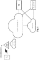
- Fig. 1 shows an exemplary network arrangement 100 according to various exemplary embodiments.
- the exemplary network arrangement 100 includes a UE 110.
- the UE 110 may be any type of electronic component that is configured to communicate via a network, e.g., mobile phones, tablet computers, desktop computers, smartphones, phablets, embedded devices, wearables (e.g., HMD, AR glasses, etc.), Internet of Things (IoT) devices, etc.
- IoT Internet of Things
- an actual network arrangement may include any number of UEs being used by any number of users.
- the example of a single UE 110 is merely provided for illustrative purposes.
- the UE 110 may be configured to communicate with one or more networks.
- the network with which the UE 110 may wirelessly communicate is a 5G NR radio access network (RAN) 120.
- the UE 110 may also communicate with other types of networks (e.g. 5G cloud RAN, a next generation RAN (NG-RAN), a long term evolution (LTE) RAN, a legacy cellular network, a WLAN, etc.) and the UE 110 may also communicate with networks over a wired connection.
- the UE 110 may establish a connection with the 5G NR RAN 120. Therefore, the UE 110 may have a 5G NR chipset to communicate with the NR RAN 120.
- the 5G NR RAN 120 may be a portion of a cellular network that may be deployed by a network carrier (e.g., Verizon, AT&T, T-Mobile, etc.).
- the 5G NR RAN 120 may include, for example, cells or base stations (Node Bs, eNodeBs, HeNBs, eNBS, gNBs, gNodeBs, macrocells, microcells, small cells, femtocells, etc.) that are configured to send and receive traffic from UEs that are equipped with the appropriate cellular chip set.
- the UE 110 may connect to the 5G NR-RAN 120 via the gNB 120A.
- the 5G NR-RAN 120 may be associated with a particular cellular provider where the UE 110 and/or the user thereof has a contract and credential information (e.g., stored on a SIM card).
- the UE 110 may transmit the corresponding credential information to associate with the 5G NR-RAN 120.
- the UE 110 may associate with a specific base station (e.g., gNB 120A).
- gNB 120A a specific base station
- reference to the 5G NR-RAN 120 is merely for illustrative purposes and any appropriate type of RAN may be used.
- the network arrangement 100 also includes a cellular core network 130, the Internet 140, an IP Multimedia Subsystem (IMS) 150, and a network services backbone 160.
- the cellular core network 130 may be considered to be the interconnected set of components that manages the operation and traffic of the cellular network.
- the cellular core network 130 also manages the traffic that flows between the cellular network and the Internet 140.
- the IMS 150 may be generally described as an architecture for delivering multimedia services to the UE 110 using the IP protocol.
- the IMS 150 may communicate with the cellular core network 130 and the Internet 140 to provide the multimedia services to the UE 110.
- the network services backbone 160 is in communication either directly or indirectly with the Internet 140 and the cellular core network 130.
- the network services backbone 160 may be generally described as a set of components (e.g., servers, network storage arrangements, etc.) that implement a suite of services that may be used to extend the functionalities of the UE 110 in communication with the various networks.
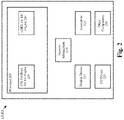
- Fig. 2 shows an exemplary UE 110 according to various exemplary embodiments.
- the UE 110 will be described with regard to the network arrangement 100 of Fig. 1 .
- the UE 110 may include a processor 205, a memory arrangement 210, a display device 215, an input/output (I/O) device 220, a transceiver 225 and other components 230.
- the other components 230 may include, for example, an audio input device, an audio output device, a power supply, a data acquisition device, ports to electrically connect the UE 110 to other electronic devices, etc.
- the processor 205 may be configured to execute a plurality of engines of the UE 110.
- the engines may include a CSI feedback for XR engine 235 and a cDRX for XR engine 240.
- the CSI feedback for XR engine 235 may perform various operations related to the exemplary CSI feedback enhancements described herein. These operations may include, but are not limited to, receiving CSI configuration information, identifying CSI resources, performing CSI measurements and reporting CSI feedback.
- the cDRX for XR engine 240 may perform various operations related to the exemplary cDRX enhancements described herein. These operations may include, but are not limited to, receiving cDRX configuration information, implementing a cDRX cycle and receiving PDCCH.
- the above referenced engines 235, 240 each being an application (e.g., a program) executed by the processor 205 is merely provided for illustrative purposes.
- the functionality associated with the engines 235, 240 may also be represented as a separate incorporated component of the UE 110 or may be a modular component coupled to the UE 110, e.g., an integrated circuit with or without firmware.
- the integrated circuit may include input circuitry to receive signals and processing circuitry to process the signals and other information.
- the engines may also be embodied as one application or separate applications.
- the functionality described for the processor 205 is split among two or more processors such as a baseband processor and an applications processor.
- the exemplary embodiments may be implemented in any of these or other configurations of a UE.
- the memory arrangement 210 may be a hardware component configured to store data related to operations performed by the UE 110.
- the display device 215 may be a hardware component configured to show data to a user while the I/O device 220 may be a hardware component that enables the user to enter inputs.
- the display device 215 and the I/O device 220 may be separate components or integrated together such as a touchscreen.
- the transceiver 225 may be a hardware component configured to establish a connection with the 5G NR-RAN 120 and/or any other appropriate type of network. Accordingly, the transceiver 225 may operate on a variety of different frequencies or channels (e.g., set of consecutive frequencies).
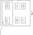
- Fig. 3 shows an exemplary base station 300 according to various exemplary embodiments.
- the base station 300 may represent any access node (e.g., gNB 120A, etc.) through which the UE 110 may establish a connection and manage network operations.
- gNB 120A any access node
- UE 110 may establish a connection and manage network operations.
- the base station 300 may include a processor 305, a memory arrangement 310, an input/output (I/O) device 315, a transceiver 320, and other components 325.
- the other components 325 may include, for example, a battery, a data acquisition device, ports to electrically connect the base station 300 to other electronic devices, etc.
- the processor 305 may be configured to execute a plurality of engines of the base station 300.
- the engines may include a CSI for XR engine 330 and a cDRX configuration for XR engine 335.
- the CSI for XR engine 330 may perform various operations related to the exemplary CSI feedback enhancements described herein.
- the operations may include but are not limited to, transmitting CSI feedback configurations information, transmitting CSI resources and receiving CSI feedback.
- the cDRX configuration for XR engine 335 may perform various operations related to the exemplary cDRX enhancements described herein.
- the operations may include, but are not limited to, transmitting cDRX configurations information and transmitting PDCCH in accordance with the cDRX configuration.
- the above noted engines 330, 335 being an application (e.g., a program) executed by the processor 305 is only exemplary.
- the functionality associated with the engines 330, 335 may also be represented as a separate incorporated component of the base station 300 or may be a modular component coupled to the base station 300, e.g., an integrated circuit with or without firmware.
- the integrated circuit may include input circuitry to receive signals and processing circuitry to process the signals and other information.
- the functionality described for the processor 305 is split among a plurality of processors (e.g., a baseband processor, an applications processor, etc.).
- the exemplary embodiments may be implemented in any of these or other configurations of a base station.
- the memory 310 may be a hardware component configured to store data related to operations performed by the base station 300.
- the I/O device 315 may be a hardware component or ports that enable a user to interact with the base station 300.
- the transceiver 320 may be a hardware component configured to exchange data with the UE 110 and any other UE in the system 100.
- the transceiver 320 may operate on a variety of different frequencies or channels (e.g., set of consecutive frequencies). Therefore, the transceiver 320 may include one or more components (e.g., radios) to enable the data exchange with the various networks and UEs.
- Fig. 4 shows a signaling diagram 400 of CSI feedback for XR according to various exemplary embodiments.
- the signaling diagram 400 is described with regard to the network arrangement 100 of Fig. 1 and the UE 110 of Fig. 2 .
- the signaling diagram 400 includes the UE 110 and the gNB 120A.
- the UE 110 receives CSI measurement and/or reporting configuration information.
- the CSI measurement and/or reporting configuration information may be provided to the UE 110 in one or more radio resource control (RRC) messages.
- the CSI measurement and/or reporting configuration information may be provided to the UE 110 in one or more access control (MAC) control elements (CEs).
- RRC radio resource control
- MAC access control
- CEs access control elements
- the exemplary embodiments are not limited to RRC messages or MAC CEs, the CSI measurement and reporting configuration information may be provided to the UE 110 in any appropriate manner.
- the gNB 120A configures CSI measurement resources to the UE 110.
- CSI resources may include channel measurement resources (CMR) and interference measurement resources (IMR).
- the CMRs may include one or more non-zero power (NZP) CSI-reference signals (RS).
- NZP non-zero power
- RS CSI-reference signals
- periodic and semi-persistent CMRs are supported. The periodicity and offset of these CMRs resources may be characterized in slots or in any other appropriate manner.
- the IMRs may include one or more zero power (ZP)-CSI-RS, NZP-CSI-RS or a combination thereof.
- ZP IMR zero power
- CSI-IM CSI-IM
- IMR informationen-reliable and low noise ratio
- NR periodic and semi-persistent IMRs are supported. The periodicity and offset of these IMRs may be characterized in slots or in any other appropriate manner.
- any reference to a particular type of IMR is merely provided for illustrative purposes, the exemplary embodiments may apply to any appropriate type of IMR.
- the UE 110 performs CSI measurements based on the CSI measurement resources.
- the UE 110 reports CSI feedback to the gNB 120A.
- the stream may be generated at cadences which are not integer multiples of NR units of time.
- XR video stream generation may occur at 60 or 120 frames per second.
- the exemplary embodiments introduce CSI measurement and reporting techniques to handle these types of timing issues in an efficient manner.
- the exemplary enhancements may be applied to only IMR.
- periodic/semi-persistent CMR may be generated at a periodicity of X milliseconds (ms) where X represents an integer value (e.g., 1, 2, 5, 10, etc.) while periodic/semi-persistent IMR may be generated at a periodicity of Y ms where Y represents a non-integer value (e.g., 25/3, 10/3, etc.).
- the exemplary enhancements may be applied to only CMR.
- the exemplary enhancements may be applied to both CMR and IMR.
- the periodicity of the CSI reporting may be the same as the DL SPS periodicity or a multiple of the DL periodicity.
- the periodicity of the CSI reporting may be non-integer.
- Fig. 5 shows an example of CSI reporting every two DL SPS reception occasions.
- the periodicity of the CSI measurement resource may also be non-integer and based on the DL SPS periodicity or a multiple of the DL periodicity.
- the CSI measurement resource periodicity may be represented by (M1/M2) where M1 and M2 each represent an integer value.
- Fig. 6 shows an example of CSI measurement resources configured as a multiple of the DL SPS periodicity.
- the CSI reporting and/or measurement configuration information may include an indication of the M1 integer, the M2 integer and an offset integer.
- Fig. 7 shows an example CSI-ReportPeriodicityAndOffset RRC parameter configured to include an indication of the supported non-integer periodicity and offset.
- the CSI reporting and measurement configuration information may include an indication of the M1 integer, the M2 integer and an offset integer.
- Fig. 8 shows an example CSI-ResourcePeriodicityAndOffset RRC parameter configured to include an indication of the supported non-integer periodicity and offset for periodic and semi-persistent NZP CSI-RS.
- the CSI reporting and measurement configuration information may include an indication of the M1 integer, the M2 integer and an offset integer.
- Fig. 9 shows an example CSI-ResourcePeriodicityAndOffset RRC parameter configured to include an indication of the supported non-integer periodicity and offset for periodic and semi-persistent CSI-IM.
- an association between the DL SPS configuration and the CSI measurement and reporting configuration may be implemented.
- the CSI reporting and measurement configuration is associated with the DL SPS configuration.
- the UE 110 may receive DL SPS configuration information and then determine the CSI measurement and reporting configuration based on the preconfigured association.
- the DL SPS configuration is associated with the CSI measurement and reporting configurations.
- the UE 110 may receive the CSI measurement and reporting configuration information and then determine the DL SPS configuration based on the preconfigured association.
- an information element may be introduced that indicates to the UE 110 a relationship between the DL SPS configuration and the CSI measurement and reporting configuration.
- the CSI-FrequencyOccupation RRC parameter is not explicitly configured according to the DL SPS PDSCH frequency allocation. Instead, the UE 110 may adapt the CSI measurement operations to the DL SPS PDSCH configuration. This allows these enhancements to be implemented without creating additional RRC signaling overhead.
- the CSI-ReportingBand RRC parameter is not explicitly configured according to the DL SPS PDSCH frequency allocation. Instead, the UE 110 may adapt the CSI reporting operations to the DL SPS PDSCH configuration. For example, if the PDSCH is from physical resource block (PRB) 10 to PRB 19, then CSI measurement is assumed for a CSI subband or subbands enclosed in the PDSCH only. This allows these enhancements to be implemented without additional RRC signaling overhead.
- PRB physical resource block
- an association of wideband and subband CSI and PDCSCH resource allocation may be implemented.
- PDSCH may support two resource allocation types, e.g., Type 0 and Type 1.
- Type 1 if interleaving is configured, this may indicate to the UE 110 that wideband CSI feedback is to be performed.
- Type 1 if interleaving is not used, this may indicate to the UE 110 that PDSCH allocation is to be quantized according to the CSI subband size and subband CSI feedback is to be performed.
- Type 0 is configured, this may indicate to the UE 110 that wideband feedback is to be performed.
- the PDSCH resource allocation type may indicate to the UE 110 how the CSI feedback is to be reported.
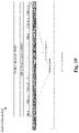
- Fig. 10 shows an example 1000 of the relationship between PDSCH allocation, CSI measurement and CSI reporting according to carious exemplary embodiments.
- the NZP CSI-RS and CSI-IM are limited to PRBs with PDSCH allocation.
- the NZP CSI-RS and the CSI-IM may be conditioned to the PDSCH.
- the exemplary embodiments are not limited to this arrangement. In other embodiments, the NZP CSI-RS and CSI-IM may be found outside the PRBs with PDSCH allocation.
- the example 1000 shows two alternatives for CSI reporting.
- the reporting subbands may be the CSI subbands that completely overlap PRBs with PDCSH allocation.
- the reporting subbands may be any CSI subband that overlaps PRBs with PDSCH allocation.
- extension to PRB n may be implemented for SCI subband-2.
- the hybrid automatic repeat request (HARQ) feedback timing may also be aligned with the traffic periodicity. Accordingly, periodic CSI feedback, semi-persistent CSI feedback or the exemplary CSI feedback triggered by DL SPS activation may be transmitted to the gNB 120A together with the HARQ feedback. This allows the UL transmission time duration to be minimized because instead of two separate PUCCH transmissions, one for CSI feedback and one for HARQ feedback, both CSI feedback and HARQ with their periodicity matched to the DL traffic can be sent in the same PUCCH. Thus, the CSI feedback may be multiplexed with the HARQ feedback on a PUCCH transmission that is matched to the periodicity of the DL traffic.
- SRS sounding reference signals
- a base station e.g., gNB 120A
- SRS may be configured in a periodic or a semi-persistent manner. Further SRS for positioning may also be configured.
- the exemplary embodiments apply to periodic SRS, semi-persistent SRS or any other appropriate type of SRS.
- the exemplary embodiments introduce a periodicity and offset for SRS transmission that is configured to match the periodicity of XR traffic.
- the periodicity and offset for SRS may be matched with downlink traffic arrival. This may facilitate coordinated beamforming.
- the periodicity and offset may be matched with uplink traffic so one transmission (e.g., SRS appended or prepended to the PUSCH) or two narrowly spaced transmissions of SRS and PUSCH may be supported.
- the base station may transmit SRS configuration information to the UE 110 using one or more RRC messages.
- the SRS configuration information may include an indication of the M1 integer, the M2 integer and an offset integer.
- Fig. 14 shows an example of an SRS-PeriodicityandOffset RRC parameter configured to include an indication of the supported non-integer periodicity and offset for SRS.
- the SRS configuration information may include a time parameter indicating a frequency at which SRS is to be transmitted.
- Fig. 15 shows an example of SRS-PeriodicityandOffset RRC parameter configured to include an indication of the supported non-integer periodicity and offset for SRS.
- the CSI feedback may be fully or partially based on the PDSCH demodulation reference signal (DMRS).
- DMRS PDSCH demodulation reference signal
- the CMR may be provided by the DMRS of the scheduled PDSCH or configured PDSCH (e.g., SPS).
- the IMR may be provided either by un-used tones in a code division multiplexing (CDM) group of the DMRS or by ZP IMR and/or NZP IMR.
- the UE 110 may calculate channel quality indicator (CQI) according to the CMR and/or IMRs. Further, if PDSCH is at a rank larger than 1, then the UE 110 may also recommend rank adaption. For example, if the PDSCH is at rank 3, the UE 110 may report a rank indicator (RI) of 1, 2 or 3 in the feedback.
- RI rank indicator
- cDRX is a power saving mechanism implemented by the UE 110 in RRC connected state.
- the cDRX cycle may comprise an onDuration during which the UE 110 is scheduled to monitor the PDCCH. Outside of the onDuration, the UE 110 may have an opportunity to utilize a sleep mode of inactivity and conserve power.
- reference to a power saving mode or a sleep mode of inactivity does not necessarily mean putting the processor 205, the transmitter, and the receiver of the UE 110 to sleep, in hibernation, or in deactivation.
- the processor 205 e.g., baseband and/or application
- the sleep mode of inactivity relates to conserving power by discontinuing a continuous processing functionality relating to operations that enable the UE 110 to receive data that may be transmitted to the UE 110 and transmit data to the network.
- the exemplary embodiments include enhancements for adapting cDRX to XR traffic which may be generated with a non-integer periodicity.
- DL traffic configured with a non-integer periodicity.
- audio and video streams may be generated at cadences which are not integer multiples of NR's default timing.
- g k f M 1 M 2 ⁇ k + I shift and k is a running index.
- SPS configuration may be adjusted with the jitter range.
- the above referenced DL traffic characteristics are merely provided for illustrative purposes. The exemplary embodiments may be applicable to DL traffic configured with non-integer periodicity in any appropriate manner.
- a symbol may be a semi-statically configured as a DL symbol (e.g., semi-static DL symbol), semi-statically configured as an UL symbol (e.g., semi-static UL symbol) or semi-statically configured as a flexible symbol. If an occasion for DRX, CSI measurement or SR transmission with a non-integer periodicity configuration is configured to collide with an UL slot or at least one static/semi-statical UL symbol in a slot, then the occasion may be deferred to the next available occasion which does not collide with any semi-static UL symbol.
- an occasion for CSI feedback with non-integer periodicity is configured to collide with an UL slot or at least one semistatical DL symbol in a slot, then the occasion may be deferred to the next available occasion which does not collide with any semi-static DL symbol.
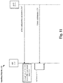
- Fig. 11 shows a signaling diagram 1100 for implementing a cDRX cycle for DL traffic configured with non-integer periodicity according to various exemplary embodiments.
- the UE 110 receives cDRX configuration information.
- This configuration information may indicate to the UE 110 the configuration of a cDRX cycle for DL traffic configured with non-integer periodicity.
- the UE 110 is camped on the gNB 120A in the RRC connected state and implements the cDRX cycle.
- an onDuration of the cDRX cycle occurs.
- the gNB 120A transmits control information to the UE 110 over the PDCCH. This control information may indicate to the UE 110 that a subsequent data reception or a subsequent transmission is scheduled.
- an additional long DRX value may be added to the DRX-config RRC parameter.
- the long DRX value may be 1000/60 which is equal to 50/3 for 60 frames per second.
- the long DRX value may be 1000/45 which is equal to 200/9 for 45 frames per second.
- these values are merely provided for illustrative purposes, any appropriate value may be utilized.
- DRX frames may be calculated using a subframe number (SFN) and a DRX offset value.
- SFN subframe number
- this floor function may be rounded or a ceil function may be used.
- the DRX cycle may be derived based on SFN value where SFN is 10 bit with a range of [0, 1023].
- the cDRX cycle may be derived using hyper-frame number (HFN) + SFN. This may not entirely eliminate the SFN wraparound issues but may mitigate the severity.
- a MAC CE may be sent in a broadcast or groupcast to multiple UEs since the SFN wrap is cell specific.
- UE 110 and the gNB 120A may be preconfigured with a non-integer DRX cycle adjustment parameter to autonomously adjust the DRX offset following the same rule.
- a combination of long DRX and short DRX may be used to match DL traffic periodicity.
- Fig. 12 shows an example of using a combination of long DRX and short DRX to match DL traffic periodicity.
- the short DRX timer may be set to 2, which indicates that there are 2 short DRX cycles within 1 long DRX cycle.
- the UE 110 may monitor the PDCCH in the normal manner. If the PDCCH indicates a new transmission (DL or UL), then the drx inactivity timer is to be started or restarted in the first symbol after the end of the PDCCH reception. In case of SPS or configured grant (CG) XR traffic, the drx inactivity timer may start as well in order to start the short DRX cycle. Thus, as shown in Fig. 12 , the MAC procedure may enable the start of the drx inactivity timer with PDSCH reception and PUSCH transmission.
- CG configured grant
- the drxStartOffset may be shifted.
- a PDCCH WUS may be used to indicated dynamic traffic.
- Fig. 13 shows an example of using PDCCH WUS to indicate dynamic traffic according to various exemplary embodiments.
- the UE 110 may skip the DRX cycle. That is, instead of monitoring the PDCCH during an onDuration, the UE 110 may utilize the sleep mode of inactivity. However, in XR, the UE 110 may wakeup every DRX cycle when the DRX cycle matches the traffic periodicity.
- a PDCCH WUS e.g., downlink control information (DCI) format 2-6
- DCI downlink control information
- the exemplary embodiments use the field within the PDCCH WUS to indicate additional information for the SPS PDSCH and CG PUSCH.
- MCS differential modulation and coding scheme
- the PDCCH WUS may be used to indicate an extension to the resource allocation when packets are relatively large for this DRX cycle.
- the PDCCH WUS may be transmitted before every DRX and either MCS or resource size for SPS and CG can be adopted before the DRX onDuration.
- PDCCH WUS may not be transmitted before short DRX.
- at least MCS adaption can be used for all DRX onDurations within he long/short DRX cycle.
- Fig. 13 shows a gNB configuration to align XR traffic before PDCCH WUS is transmitted.
- a user equipment comprises a transceiver configured to communicate with a network and a processor communicatively coupled to the transceiver and configured to perform operations comprising receiving channel state information (CSI) configuration information corresponding to downlink new radio (NR) traffic with non-integer periodicity, wherein the CSI configuration information includes one of CSI measurement configuration information, CSI reporting configuration information or CSI measurement configuration information and CSI reporting configuration information, receiving CSI measurement resources and reporting CSI feedback to a network.
- CSI channel state information
- NR downlink new radio
- a base station comprises a transceiver configured to communicate with a user equipment (UE) and a processor communicatively coupled to the transceiver and configured to perform operations comprising transmitting channel state information (CSI) configuration information corresponding to downlink new radio (NR) traffic with non-integer periodicity to a user equipment (UE), wherein the CSI configuration information includes one or more of CSI measurement configuration information and CSI reporting configuration information, transmitting CSI measurement resources and receiving CSI feedback from the UE.
- CSI channel state information
- NR downlink new radio
- a user equipment comprises a transceiver configured to communicate with a network and a processor communicatively coupled to the transceiver and configured to perform operations comprising receiving connected discontinuous reception (cDRX) configuration information for downlink new radio (NR) traffic with non-integer periodicity, implementing a cDRX cycle based on the configuration information and receiving physical downlink control channel (PDCCH) during an onDuration of the cDRX cycle.
- cDRX connected discontinuous reception
- NR downlink new radio
- PDCCH physical downlink control channel
- a base station comprises a transceiver configured to communicate with a user equipment (UE) and a processor communicatively coupled to the transceiver and configured to perform operations comprising transmitting connected discontinuous reception (cDRX) configuration information for downlink new radio (NR) traffic with non-integer periodicity to a user equipment (UE) and transmitting physical downlink control channel (PDCCH) during an onDuration of a cDRX cycle implemented by the UE.
- cDRX connected discontinuous reception
- NR downlink new radio
- PDCCH physical downlink control channel
- a processor of a user equipment is configured to perform operations comprising receiving sounding reference signal (SRS) configuration information corresponding to new radio (NR) traffic with non-integer periodicity and transmitting SRS to a base station of a network.
- SRS sounding reference signal
- NR new radio
- the processor of the fifth example wherein the periodicity of the SRS is a non-integer periodicity configured based on downlink traffic.
- the processor of the fifth example wherein the periodicity of the SRS is a non-integer periodicity configured based on uplink traffic.
- the processor of the seventh example wherein the SRS is appended or prepended to a physical uplink shared channel (PUSCH).
- PUSCH physical uplink shared channel
- the processor of the eighth example wherein the PUSCH is a configured grant PUCSH.
- the processor of the fifth example wherein the SRS configuration information is included in an RRC message comprising a first integer, a second integer and an offset integer.
- the processor of the fifth example wherein the SRS configuration information is included in an RRC message comprising a time based parameter indicating a frequency at which SRS is to be transmitted and an offset integer.
- a processor of a base station is configured to perform operations comprising transmitting connected discontinuous reception (cDRX) configuration information for downlink new radio (NR) traffic with non-integer periodicity to a user equipment (UE) and transmitting physical downlink control channel (PDCCH) during an onDuration of a cDRX cycle implemented by the UE.
- cDRX connected discontinuous reception
- NR downlink new radio
- PDCCH physical downlink control channel
- the processor of the twelfth example the operations further comprising transmitting a medium access control (MAC) control element (CE) indicating a change to a drxStartOffset.
- MAC medium access control
- CE control element
- the processor of the thirteenth example wherein the MAC CE is sent in a broadcast or a groupcast.
- the processor of the twelfth example the operations further comprising transmitting a PDCCH wake up signal (WUS), wherein the PDCCH WUS comprises information for semi-persistent scheduling (SPS) physical downlink shared channel (PDSCH).
- WUS PDCCH wake up signal
- SPS semi-persistent scheduling
- PDSCH physical downlink shared channel
- the processor of the sixteenth example wherein the information comprises a differential modulation and coding scheme (MCS) or an indication to extend the resource allocation.
- MCS differential modulation and coding scheme
- the processor of the twelfth example the operations further comprising transmitting a PDCCH wake up signal (WUS), wherein the PDCCH WUS comprises information for configured grant (CG) physical uplink shared channel (PUSCH).
- WUS PDCCH wake up signal
- CG configured grant
- PUSCH physical uplink shared channel
- the processor of the twelfth example the operations further comprising transmitting a PDCCH wake up signal (WUS), wherein downlink traffic is aligned before the PDCCH WUS.
- WUS PDCCH wake up signal
- a processor of a user equipment is configured to perform operations comprising receiving channel state information (CSI) configuration information corresponding to downlink new radio (NR) traffic with non-integer periodicity, wherein the CSI configuration information includes one of CSI measurement configuration information, CSI reporting configuration information or CSI measurement configuration information and CSI reporting configuration information, receiving CSI measurement resources; and reporting CSI feedback to a network.
- CSI channel state information
- NR downlink new radio
- the processor of the twentieth example the operations further comprising identifying Type 1 physical downlink shared channel (PDSCH) resource allocation with interleaving or Type 0 PDSCH resource allocation and determining that wideband CSI feedback is to be used based on the identifying.
- PDSCH physical downlink shared channel
- the processor of the twentieth example the operations further comprising identifying Type 1 physical downlink shared channel (PDSCH) resource allocation without interleaving and determining that subband CSI feedback is to be used based on the identifying.
- PDSCH physical downlink shared channel
- the processor of the twentieth example wherein the CSI measurement resources are limited to physical resource blocks (PRBs) with physical downlink shared channel (PDSCH) allocation.
- PRBs physical resource blocks
- PDSCH physical downlink shared channel
- the processor of the twentieth example, wherein reporting the CSI feedback includes multiplexing the CSI feedback and hybrid automatic repeat request (HARQ) feedback.
- HARQ hybrid automatic repeat request
- the processor of the twentieth example wherein the channel measurement resources (CMRs) are provided by demodulation reference signals (DMRS).
- CMRs channel measurement resources
- DMRS demodulation reference signals
- the processor of the twentieth example wherein the interference measurement resources (IMRs) are provided by one of unused tones in a code division multiplexing (CDM) group of demodulation reference signals (DMRS), zero power (ZP) IMR or non-zero power (NZP) IMR.
- CDM code division multiplexing
- DMRS demodulation reference signals
- ZP zero power
- NZP non-zero power
- a processor of a base station is configured to perform operations comprising transmitting channel state information (CSI) configuration information corresponding to downlink new radio (NR) traffic with non-integer periodicity to a user equipment (UE), wherein the CSI configuration information includes one or more of CSI measurement configuration information and CSI reporting configuration information, transmitting CSI measurement resources and receiving CSI feedback from the UE.
- CSI channel state information
- NR downlink new radio
- the processor of the twenty seventh example wherein the CSI measurement and reporting configuration information is included in a radio resource control (RRC) message comprising a first integer, a second integer and an offset integer and wherein the first integer and the second integer are to be used by the UE to derive a non-integer CSI reporting periodicity.
- RRC radio resource control
- the processor of the twenty eighth example wherein the CSI measurement and reporting configuration information is included in a radio resource control (RRC) message comprising a first integer, a second integer and an offset integer and wherein the first integer and the second integer are used to by the UE to derive a non-integer periodicity for channel measurement resources (CMR).
- RRC radio resource control
- the processor of the twenty eighth example wherein the CSI measurement and reporting configuration information is included in a radio resource control (RRC) message comprising a first integer, a second integer and an offset integer and wherein the first integer and the second integer are used to by the UE derive a non-integer periodicity for interference measurement resources (IMR).
- RRC radio resource control
- the processor of the twenty eighth example the operations further comprising transmitting an information element (IE) to the UE indicating a relationship between downlink semi-persistent scheduling (SPS) and CSI measurement and reporting occasions.
- IE information element
- An exemplary hardware platform for implementing the exemplary embodiments may include, for example, an Intel x86 based platform with compatible operating system, a Windows OS, a Mac platform and MAC OS, a mobile device having an operating system such as iOS, Android, etc.
- the exemplary embodiments of the above described method may be embodied as a program containing lines of code stored on a non-transitory computer readable storage medium that, when compiled, may be executed on a processor or microprocessor.
- personally identifiable information should follow privacy policies and practices that are generally recognized as meeting or exceeding industry or governmental requirements for maintaining the privacy of users.
- personally identifiable information data should be managed and handled so as to minimize risks of unintentional or unauthorized access or use, and the nature of authorized use should be clearly indicated to users.
Landscapes
- Engineering & Computer Science (AREA)
- Computer Networks & Wireless Communication (AREA)
- Signal Processing (AREA)
- Mobile Radio Communication Systems (AREA)
Abstract
Description
- This application claims priority to PCT Application
PCT/CN2021/098692 entitled "Handling New Radio (NR) Traffic Configured with Non-Integer Periodicity," filed on June 7, 2021 - In a new radio (NR) network, for any of a variety of different reasons, there may be traffic that is generated at cadences which are not integer multiples of the units of time supported in NR. For example, augmented reality (AR) and virtual reality (VR) applications may have traffic that is not supported by any NR unit of time. In NR, the existing solution to address this type of timing issue is the over-provisioning of resources. However, this is an inefficient use of network resources and may cause a user equipment (UE) to experience a power drain. Accordingly, there is a need for enhancements for managing NR traffic that does not match NR's default timing.
- Some exemplary embodiments are related to a processor of a user equipment (UE) configured to perform operations. The operations include receiving channel state information (CSI) configuration information corresponding to downlink new radio (NR) traffic with non-integer periodicity, wherein the CSI configuration information includes one of CSI measurement configuration information, CSI reporting configuration information or CSI measurement configuration information and CSI reporting configuration information, receiving CSI measurement resources and reporting CSI feedback to a network.
- Other exemplary embodiments are related to a processor of a base station configured to perform operations. The operations include transmitting channel state information (CSI) configuration information corresponding to downlink new radio (NR) traffic with non-integer periodicity to a user equipment (UE), wherein the CSI configuration information includes one or more of CSI measurement configuration information and CSI reporting configuration information, transmitting CSI measurement resources and receiving CSI feedback from the UE.
- Still further exemplary embodiments are related to a processor of a user equipment (UE) configured to perform operations. The operations include receiving connected discontinuous reception (cDRX) configuration information for downlink new radio (NR) traffic with non-integer periodicity, implementing a cDRX cycle based on the configuration information and receiving physical downlink control channel (PDCCH) during an onDuration of the cDRX cycle.
- Additional exemplary embodiments are related to a processor of a base station configured to perform operations. The operations include transmitting connected discontinuous reception (cDRX) configuration information for downlink new radio (NR) traffic with non-integer periodicity to a user equipment (UE) and transmitting physical downlink control channel (PDCCH) during an onDuration of a cDRX cycle implemented by the UE.
-
-
Fig. 1 shows an exemplary network arrangement according to various exemplary embodiments. -
Fig. 2 shows an exemplary user equipment (UE) according to various exemplary embodiments. -
Fig. 3 shows an exemplary base station according to various exemplary embodiments. -
Fig. 4 shows a signaling diagram of channel state information (CSI) feedback for eXtended reality (XR) according to various exemplary embodiments. -
Fig. 5 shows an example of CSI reporting every two downlink (DL) semi-persistent scheduling (SPS) reception occasions. -
Fig. 6 shows an example of CSI measurement resources configured as a multiple of the DL SPS periodicity. -
Fig. 7 shows an example CSI-ReportPeriodicityAndOffset radio resource control (RRC) parameter configured to include an indication of the supported non-integer periodicity and offset. -
Fig. 8 shows an example CSI-ResourcePeriodicityAndOffset RRC parameter configured to include an indication of the supported non-integer periodicity and offset for periodic and semi-persistent non-zero power (NZP) CSI-RS. -
Fig. 9 shows an example CSI-ResourcePeriodicityAndOffset RRC parameter configured to include an indication of the supported non-integer periodicity and offset for periodic and semi-persistent CSI-IM. -
Fig. 10 shows an example of the relationship between physical downlink shared channel (PDSCH) allocation, CSI measurement and CSI reporting according to various exemplary embodiments. -
Fig. 11 shows a signaling diagram for implementing a connected discontinuous reception (cDRX) cycle for DL traffic configured with non-integer periodicity according to various exemplary embodiments. -
Fig. 12 shows an example of using a combination of long DRX and short DRX to match DL traffic periodicity. -
Fig. 13 shows an example of using physical downlink control channel (PDCCH) wake-up signal (WUS) to indicate dynamic traffic according to various exemplary embodiments. -
Fig. 14 shows an example of an SRS-PeriodicityandOffset RRC parameter configured to include an indication of the supported non-integer periodicity and offset for sounding reference signals (SRS) according to various exemplary embodiments. -
Fig. 15 shows an example of SRS-PeriodicityandOffset RRC parameter configured to include an indication of the supported non-integer periodicity and offset for SRS according to various exemplary embodiments. - The exemplary embodiments may be further understood with reference to the following description and the related appended drawings, wherein like elements are provided with the same reference numerals. The exemplary embodiments introduce techniques for handling traffic that may not match integer multiples of the units of time supported in new radio (NR). In one aspect, the exemplary embodiments relate to channel state information (CSI) feedback. As will be described in more detail below, some of the exemplary techniques described herein may enable a user equipment (UE) to implement power efficient CSI feedback for traffic such as eXtended reality (XR) traffic that may be generated at cadences which are not integer multiples of NR units of time (e.g., non-integer periodicity). In another aspect, the exemplary embodiments relate to connected discontinuous reception (cDRX). As will be described in more detail below, some of the exemplary techniques described herein enable the UE to implement cDRX for NR traffic that may be generated at cadences which are not integer multiples of NR's default timing.
- The exemplary embodiments are described with regard to eXtended Reality (XR). Those skilled in the art will understand that XR is an umbrella term for different types of realities and may generally refer to real-and-virtual combined environments and associated human-machine interactions generated by computer technology and wearables. To provide some examples, the term XR may encompass augmented reality (AR), mixed reality (MR) and virtual reality (VR). However, any reference to XR being specific to a particular use case or type of traffic is merely provided for illustrative purposes. The exemplary embodiments apply to any type of NR traffic that may be generated at cadences which are not integer multiples of NR's default timing.
- During operation, XR services may utilize multiple data flows in the uplink (UL) and/or downlink (DL). For example, in the DL, there may be a video stream, an audio stream and/or a data stream. In the UL, there may be a control stream and/or a pose stream. From a physical channel perspective, there may be different control channels and shared channels for each stream or multiple streams may share a control channel and/or shared channel. In some configurations, each stream may have different quality of service (QoS) requirements (e.g., block error rate (BLER), latency requirements, etc.).
- In addition, the exemplary embodiments are described with regard to a UE. Those skilled in the art will understand that the UE may be any type of electronic component that is configured to communicate via a network, e.g., mobile phones, tablet computers, desktop computers, smartphones, phablets, embedded devices, wearables, Internet of Things (IoT) devices, etc. With regard to XR, in some configurations, the UE may be paired with a wearable device (e.g., a head mounted display (HMD), AR glasses, etc.). In this type of configuration, the UE may communicate directly with the network and then relay data to the wearable device which presents the XR content to the user (e.g., AR, VR, MR, etc.). In other configurations, the UE may be a wearable device that communicates directly with the network and presents the XR content to the user. Therefore, the UE as described herein is used to represent any electronic component that directly communicates with the network.
- Although the exemplary embodiments are described with regard to providing enhancements for XR services, the exemplary embodiments are not limited to XR services and may apply to any type of NR traffic configured with non-integer periodicity. To provide another example, in industrial Internet of things (IIoT), traffic may be generated from an installed system with a long use life. In this type of scenario, it is difficult to modify the traffic generation periodicity to match any of NR's units of time. Those skilled in the art will understand how the exemplary techniques described herein may be applied to IIoT and any other type of NR traffic that may not match NR's default timing.
- In one aspect, the exemplary embodiments introduce CSI feedback enhancements for XR. As will be described in more detail below, CSI feedback enhancements including measurement and/or reporting matched to traffic arrival are introduced to improve UE power saving and performance with regard to XR (or any other type of traffic that may not match NR's existing timing). Further, exemplary enhancements to enable periodic (P) and semi-persistent (SP) CSI measurement and reporting matched to the application traffic periodicity and offset are introduced In addition, CSI feedback measurement and/or reporting matched to semi-persistent scheduling (SPS) physical downlink shared channel (PDSCH) reception are introduced. The exemplary CSI feedback enhancements described herein may be used in conjunction with currently implemented CSI feedback techniques, future implementations of CSI feedback techniques or independently from other CSI feedback techniques.
- In another aspect, the exemplary embodiments introduce cDRX enhancements for XR. As will be described in more detail below, UE power efficient cDRX configurations for XR traffic (or any other type of NR traffic that may not match NR's default timing) are introduced. These enhancements may include non-integer periodicity for cDRX configuration, using a combination of long DRX and short DRX to match traffic periodicity and using a physical downlink control channel (PDCCH) wake up signal (WUS) to indicate dynamic traffic. The exemplary cDRX enhancements described herein may be used in conjunction with currently implemented cDRX mechanisms, future implementations of cDRX mechanisms or independently from other cDRX mechanisms.
-
Fig. 1 shows anexemplary network arrangement 100 according to various exemplary embodiments. Theexemplary network arrangement 100 includes aUE 110. Those skilled in the art will understand that theUE 110 may be any type of electronic component that is configured to communicate via a network, e.g., mobile phones, tablet computers, desktop computers, smartphones, phablets, embedded devices, wearables (e.g., HMD, AR glasses, etc.), Internet of Things (IoT) devices, etc. It should also be understood that an actual network arrangement may include any number of UEs being used by any number of users. Thus, the example of asingle UE 110 is merely provided for illustrative purposes. - The
UE 110 may be configured to communicate with one or more networks. In the example of thenetwork configuration 100, the network with which theUE 110 may wirelessly communicate is a 5G NR radio access network (RAN) 120. However, theUE 110 may also communicate with other types of networks (e.g. 5G cloud RAN, a next generation RAN (NG-RAN), a long term evolution (LTE) RAN, a legacy cellular network, a WLAN, etc.) and theUE 110 may also communicate with networks over a wired connection. With regard to the exemplary embodiments, theUE 110 may establish a connection with the5G NR RAN 120. Therefore, theUE 110 may have a 5G NR chipset to communicate with theNR RAN 120. - The
5G NR RAN 120 may be a portion of a cellular network that may be deployed by a network carrier (e.g., Verizon, AT&T, T-Mobile, etc.). The5G NR RAN 120 may include, for example, cells or base stations (Node Bs, eNodeBs, HeNBs, eNBS, gNBs, gNodeBs, macrocells, microcells, small cells, femtocells, etc.) that are configured to send and receive traffic from UEs that are equipped with the appropriate cellular chip set. - The
UE 110 may connect to the 5G NR-RAN 120 via thegNB 120A. Those skilled in the art will understand that any association procedure may be performed for theUE 110 to connect to the 5G NR-RAN 120. For example, as discussed above, the 5G NR-RAN 120 may be associated with a particular cellular provider where theUE 110 and/or the user thereof has a contract and credential information (e.g., stored on a SIM card). Upon detecting the presence of the 5G NR-RAN 120, theUE 110 may transmit the corresponding credential information to associate with the 5G NR-RAN 120. More specifically, theUE 110 may associate with a specific base station (e.g.,gNB 120A). However, as mentioned above, reference to the 5G NR-RAN 120 is merely for illustrative purposes and any appropriate type of RAN may be used. - The
network arrangement 100 also includes acellular core network 130, theInternet 140, an IP Multimedia Subsystem (IMS) 150, and anetwork services backbone 160. Thecellular core network 130 may be considered to be the interconnected set of components that manages the operation and traffic of the cellular network. Thecellular core network 130 also manages the traffic that flows between the cellular network and theInternet 140. TheIMS 150 may be generally described as an architecture for delivering multimedia services to theUE 110 using the IP protocol. TheIMS 150 may communicate with thecellular core network 130 and theInternet 140 to provide the multimedia services to theUE 110. Thenetwork services backbone 160 is in communication either directly or indirectly with theInternet 140 and thecellular core network 130. Thenetwork services backbone 160 may be generally described as a set of components (e.g., servers, network storage arrangements, etc.) that implement a suite of services that may be used to extend the functionalities of theUE 110 in communication with the various networks. -
Fig. 2 shows anexemplary UE 110 according to various exemplary embodiments. TheUE 110 will be described with regard to thenetwork arrangement 100 ofFig. 1 . TheUE 110 may include aprocessor 205, amemory arrangement 210, adisplay device 215, an input/output (I/O)device 220, atransceiver 225 andother components 230. Theother components 230 may include, for example, an audio input device, an audio output device, a power supply, a data acquisition device, ports to electrically connect theUE 110 to other electronic devices, etc. - The
processor 205 may be configured to execute a plurality of engines of theUE 110. For example, the engines may include a CSI feedback forXR engine 235 and a cDRX forXR engine 240. The CSI feedback forXR engine 235 may perform various operations related to the exemplary CSI feedback enhancements described herein. These operations may include, but are not limited to, receiving CSI configuration information, identifying CSI resources, performing CSI measurements and reporting CSI feedback. The cDRX forXR engine 240 may perform various operations related to the exemplary cDRX enhancements described herein. These operations may include, but are not limited to, receiving cDRX configuration information, implementing a cDRX cycle and receiving PDCCH. - The above referenced
engines processor 205 is merely provided for illustrative purposes. The functionality associated with theengines UE 110 or may be a modular component coupled to theUE 110, e.g., an integrated circuit with or without firmware. For example, the integrated circuit may include input circuitry to receive signals and processing circuitry to process the signals and other information. The engines may also be embodied as one application or separate applications. In addition, in some UEs, the functionality described for theprocessor 205 is split among two or more processors such as a baseband processor and an applications processor. The exemplary embodiments may be implemented in any of these or other configurations of a UE. - The
memory arrangement 210 may be a hardware component configured to store data related to operations performed by theUE 110. Thedisplay device 215 may be a hardware component configured to show data to a user while the I/O device 220 may be a hardware component that enables the user to enter inputs. Thedisplay device 215 and the I/O device 220 may be separate components or integrated together such as a touchscreen. Thetransceiver 225 may be a hardware component configured to establish a connection with the 5G NR-RAN 120 and/or any other appropriate type of network. Accordingly, thetransceiver 225 may operate on a variety of different frequencies or channels (e.g., set of consecutive frequencies). -
Fig. 3 shows anexemplary base station 300 according to various exemplary embodiments. Thebase station 300 may represent any access node (e.g.,gNB 120A, etc.) through which theUE 110 may establish a connection and manage network operations. - The
base station 300 may include aprocessor 305, amemory arrangement 310, an input/output (I/O)device 315, atransceiver 320, andother components 325. Theother components 325 may include, for example, a battery, a data acquisition device, ports to electrically connect thebase station 300 to other electronic devices, etc. - The
processor 305 may be configured to execute a plurality of engines of thebase station 300. For example, the engines may include a CSI forXR engine 330 and a cDRX configuration for XR engine 335. The CSI forXR engine 330 may perform various operations related to the exemplary CSI feedback enhancements described herein. The operations may include but are not limited to, transmitting CSI feedback configurations information, transmitting CSI resources and receiving CSI feedback. The cDRX configuration for XR engine 335 may perform various operations related to the exemplary cDRX enhancements described herein. The operations may include, but are not limited to, transmitting cDRX configurations information and transmitting PDCCH in accordance with the cDRX configuration. - The above noted
engines 330, 335 being an application (e.g., a program) executed by theprocessor 305 is only exemplary. The functionality associated with theengines 330, 335 may also be represented as a separate incorporated component of thebase station 300 or may be a modular component coupled to thebase station 300, e.g., an integrated circuit with or without firmware. For example, the integrated circuit may include input circuitry to receive signals and processing circuitry to process the signals and other information. In addition, in some base stations, the functionality described for theprocessor 305 is split among a plurality of processors (e.g., a baseband processor, an applications processor, etc.). The exemplary embodiments may be implemented in any of these or other configurations of a base station. - The
memory 310 may be a hardware component configured to store data related to operations performed by thebase station 300. The I/O device 315 may be a hardware component or ports that enable a user to interact with thebase station 300. Thetransceiver 320 may be a hardware component configured to exchange data with theUE 110 and any other UE in thesystem 100. Thetransceiver 320 may operate on a variety of different frequencies or channels (e.g., set of consecutive frequencies). Therefore, thetransceiver 320 may include one or more components (e.g., radios) to enable the data exchange with the various networks and UEs. - As mentioned above, in one aspect, the exemplary embodiments introduce CSI feedback enhancements for XR.
Fig. 4 shows a signaling diagram 400 of CSI feedback for XR according to various exemplary embodiments. The signaling diagram 400 is described with regard to thenetwork arrangement 100 ofFig. 1 and theUE 110 ofFig. 2 . - The signaling diagram 400 includes the
UE 110 and thegNB 120A. In 405, theUE 110 receives CSI measurement and/or reporting configuration information. In some embodiments, the CSI measurement and/or reporting configuration information may be provided to theUE 110 in one or more radio resource control (RRC) messages. In other embodiments, the CSI measurement and/or reporting configuration information may be provided to theUE 110 in one or more access control (MAC) control elements (CEs). However, the exemplary embodiments are not limited to RRC messages or MAC CEs, the CSI measurement and reporting configuration information may be provided to theUE 110 in any appropriate manner. - Various CSI feedback enhancements for XR will be described in detail below. Subsequently, examples of how the network may provide the
UE 110 with the corresponding CSI measurement and reporting configuration information will be provided. - In 410, the
gNB 120A configures CSI measurement resources to theUE 110. CSI resources may include channel measurement resources (CMR) and interference measurement resources (IMR). The CMRs may include one or more non-zero power (NZP) CSI-reference signals (RS). In NR, periodic and semi-persistent CMRs are supported. The periodicity and offset of these CMRs resources may be characterized in slots or in any other appropriate manner. Throughout this description, any reference to a particular type of CMR is merely provided for illustrative purposes, the exemplary embodiments may apply to any appropriate type of CMR. - The IMRs may include one or more zero power (ZP)-CSI-RS, NZP-CSI-RS or a combination thereof. Throughout this description, the terms "ZP IMR" and "CSI-IM" may be used interchangeably to identify the same type of CSI resources and "IMR" may refer to "ZP IMR," "NZP IMR" or a combination of "ZP IMR" and NZP IMR.". In NR, periodic and semi-persistent IMRs are supported. The periodicity and offset of these IMRs may be characterized in slots or in any other appropriate manner. Throughout this description, any reference to a particular type of IMR is merely provided for illustrative purposes, the exemplary embodiments may apply to any appropriate type of IMR.
- In 415, the
UE 110 performs CSI measurements based on the CSI measurement resources. In 420, theUE 110 reports CSI feedback to thegNB 120A. - For XR service, the stream may be generated at cadences which are not integer multiples of NR units of time. To provide one example, XR video stream generation may occur at 60 or 120 frames per second. The exemplary embodiments introduce CSI measurement and reporting techniques to handle these types of timing issues in an efficient manner.
- In some embodiments, the exemplary enhancements may be applied to only IMR. For example, periodic/semi-persistent CMR may be generated at a periodicity of X milliseconds (ms) where X represents an integer value (e.g., 1, 2, 5, 10, etc.) while periodic/semi-persistent IMR may be generated at a periodicity of Y ms where Y represents a non-integer value (e.g., 25/3, 10/3, etc.). In another embodiments, the exemplary enhancements may be applied to only CMR. In a further embodiment, the exemplary enhancements may be applied to both CMR and IMR.
- In one example, the periodicity of the CSI reporting may be the same as the DL SPS periodicity or a multiple of the DL periodicity. The periodicity of the CSI reporting may be non-integer.
Fig. 5 shows an example of CSI reporting every two DL SPS reception occasions. - The periodicity of the CSI measurement resource may also be non-integer and based on the DL SPS periodicity or a multiple of the DL periodicity. For example, the CSI measurement resource periodicity may be represented by (M1/M2) where M1 and M2 each represent an integer value.
Fig. 6 shows an example of CSI measurement resources configured as a multiple of the DL SPS periodicity. - To enable periodic and semi-persistent CSI reporting with non-integer periodicity and offset, the CSI reporting and/or measurement configuration information may include an indication of the M1 integer, the M2 integer and an offset integer.
Fig. 7 shows an example CSI-ReportPeriodicityAndOffset RRC parameter configured to include an indication of the supported non-integer periodicity and offset. - To indicate to the
UE 110 the non-integer periodicity and offset for the CMR configuration, the CSI reporting and measurement configuration information may include an indication of the M1 integer, the M2 integer and an offset integer.Fig. 8 shows an example CSI-ResourcePeriodicityAndOffset RRC parameter configured to include an indication of the supported non-integer periodicity and offset for periodic and semi-persistent NZP CSI-RS. - To indicate to the
UE 110 the non-integer periodicity and offset for the IMR configuration, the CSI reporting and measurement configuration information may include an indication of the M1 integer, the M2 integer and an offset integer.Fig. 9 shows an example CSI-ResourcePeriodicityAndOffset RRC parameter configured to include an indication of the supported non-integer periodicity and offset for periodic and semi-persistent CSI-IM. - In some embodiments, an association between the DL SPS configuration and the CSI measurement and reporting configuration may be implemented. In one example, the CSI reporting and measurement configuration is associated with the DL SPS configuration. Thus, in this example, the
UE 110 may receive DL SPS configuration information and then determine the CSI measurement and reporting configuration based on the preconfigured association. In another example, the DL SPS configuration is associated with the CSI measurement and reporting configurations. Thus, in this example, theUE 110 may receive the CSI measurement and reporting configuration information and then determine the DL SPS configuration based on the preconfigured association. In a further example, an information element (IE) may be introduced that indicates to the UE 110 a relationship between the DL SPS configuration and the CSI measurement and reporting configuration. - For the exemplary enhancements to the CSI measurement resources, it may be beneficial to restrict the presence of CSI-RS to the DL SPS PDSCH. In some embodiments, the CSI-FrequencyOccupation RRC parameter is not explicitly configured according to the DL SPS PDSCH frequency allocation. Instead, the
UE 110 may adapt the CSI measurement operations to the DL SPS PDSCH configuration. This allows these enhancements to be implemented without creating additional RRC signaling overhead. - Further, in some embodiments, the CSI-ReportingBand RRC parameter is not explicitly configured according to the DL SPS PDSCH frequency allocation. Instead, the
UE 110 may adapt the CSI reporting operations to the DL SPS PDSCH configuration. For example, if the PDSCH is from physical resource block (PRB) 10 to PRB 19, then CSI measurement is assumed for a CSI subband or subbands enclosed in the PDSCH only. This allows these enhancements to be implemented without additional RRC signaling overhead. - In some embodiments, an association of wideband and subband CSI and PDCSCH resource allocation may be implemented. For example, PDSCH may support two resource allocation types, e.g.,
Type 0 andType 1. ForType 1, if interleaving is configured, this may indicate to theUE 110 that wideband CSI feedback is to be performed. ForType 1, if interleaving is not used, this may indicate to theUE 110 that PDSCH allocation is to be quantized according to the CSI subband size and subband CSI feedback is to be performed. WhenType 0 is configured, this may indicate to theUE 110 that wideband feedback is to be performed. Thus, the PDSCH resource allocation type may indicate to theUE 110 how the CSI feedback is to be reported. -
Fig. 10 shows an example 1000 of the relationship between PDSCH allocation, CSI measurement and CSI reporting according to carious exemplary embodiments. In the example 1000, the NZP CSI-RS and CSI-IM are limited to PRBs with PDSCH allocation. Thus, the NZP CSI-RS and the CSI-IM may be conditioned to the PDSCH. However, the exemplary embodiments are not limited to this arrangement. In other embodiments, the NZP CSI-RS and CSI-IM may be found outside the PRBs with PDSCH allocation. - The example 1000 shows two alternatives for CSI reporting. In alternative one, the reporting subbands may be the CSI subbands that completely overlap PRBs with PDCSH allocation. In alternative two, the reporting subbands may be any CSI subband that overlaps PRBs with PDSCH allocation. In some embodiments, extension to PRB n may be implemented for SCI subband-2.
- Since the CSI timing may be configured to align with the traffic periodicity, in some embodiments, the hybrid automatic repeat request (HARQ) feedback timing may also be aligned with the traffic periodicity. Accordingly, periodic CSI feedback, semi-persistent CSI feedback or the exemplary CSI feedback triggered by DL SPS activation may be transmitted to the
gNB 120A together with the HARQ feedback. This allows the UL transmission time duration to be minimized because instead of two separate PUCCH transmissions, one for CSI feedback and one for HARQ feedback, both CSI feedback and HARQ with their periodicity matched to the DL traffic can be sent in the same PUCCH. Thus, the CSI feedback may be multiplexed with the HARQ feedback on a PUCCH transmission that is matched to the periodicity of the DL traffic. - In addition, sounding reference signals (SRS) may be configured with a non-integer periodicity and offset. Those skilled in the art will understand that SRS generally refers to an uplink reference signal that may be used by a base station (e.g.,
gNB 120A) to estimate channel quality. SRS may be configured in a periodic or a semi-persistent manner. Further SRS for positioning may also be configured. The exemplary embodiments apply to periodic SRS, semi-persistent SRS or any other appropriate type of SRS. - The exemplary embodiments introduce a periodicity and offset for SRS transmission that is configured to match the periodicity of XR traffic. In some embodiments, the periodicity and offset for SRS may be matched with downlink traffic arrival. This may facilitate coordinated beamforming. In other embodiments, the periodicity and offset may be matched with uplink traffic so one transmission (e.g., SRS appended or prepended to the PUSCH) or two narrowly spaced transmissions of SRS and PUSCH may be supported.
- To indicate to the
UE 110 the non-integer periodicity and offset for the SRS configuration, the base station may transmit SRS configuration information to theUE 110 using one or more RRC messages. The SRS configuration information may include an indication of the M1 integer, the M2 integer and an offset integer.Fig. 14 shows an example of an SRS-PeriodicityandOffset RRC parameter configured to include an indication of the supported non-integer periodicity and offset for SRS. - Alternatively, instead of M1 and M2 integers, the SRS configuration information may include a time parameter indicating a frequency at which SRS is to be transmitted.
Fig. 15 shows an example of SRS-PeriodicityandOffset RRC parameter configured to include an indication of the supported non-integer periodicity and offset for SRS. - In some embodiments, the CSI feedback may be fully or partially based on the PDSCH demodulation reference signal (DMRS). When CSI feedback is based on PDSCH DMRS, the CMR may be provided by the DMRS of the scheduled PDSCH or configured PDSCH (e.g., SPS). The IMR may be provided either by un-used tones in a code division multiplexing (CDM) group of the DMRS or by ZP IMR and/or NZP IMR. The
UE 110 may calculate channel quality indicator (CQI) according to the CMR and/or IMRs. Further, if PDSCH is at a rank larger than 1, then theUE 110 may also recommend rank adaption. For example, if the PDSCH is atrank 3, theUE 110 may report a rank indicator (RI) of 1, 2 or 3 in the feedback. - In another aspect, the exemplary embodiments relate to cDRX for XR. Those skilled in the art will understand that cDRX is a power saving mechanism implemented by the
UE 110 in RRC connected state. The cDRX cycle may comprise an onDuration during which theUE 110 is scheduled to monitor the PDCCH. Outside of the onDuration, theUE 110 may have an opportunity to utilize a sleep mode of inactivity and conserve power. Throughout this description, reference to a power saving mode or a sleep mode of inactivity does not necessarily mean putting theprocessor 205, the transmitter, and the receiver of theUE 110 to sleep, in hibernation, or in deactivation. For example, the processor 205 (e.g., baseband and/or application) may continue to execute other applications or processes. The sleep mode of inactivity relates to conserving power by discontinuing a continuous processing functionality relating to operations that enable theUE 110 to receive data that may be transmitted to theUE 110 and transmit data to the network. The exemplary embodiments include enhancements for adapting cDRX to XR traffic which may be generated with a non-integer periodicity. - As indicated above, in NR, there may be DL traffic configured with a non-integer periodicity. For example, in XR, audio and video streams may be generated at cadences which are not integer multiples of NR's default timing. In one configuration of DL traffic with non-integer periodicity, the
UE 110 may expect SPS transmissions from the network at slot mod(g(k),NSlotPerRadioFrame ) where
- In a TDD system, there may be DL slots, UL slots and mixed slots (with both DL and UL symbols) in a radio frame. In some embodiments, a symbol may be a semi-statically configured as a DL symbol (e.g., semi-static DL symbol), semi-statically configured as an UL symbol (e.g., semi-static UL symbol) or semi-statically configured as a flexible symbol. If an occasion for DRX, CSI measurement or SR transmission with a non-integer periodicity configuration is configured to collide with an UL slot or at least one static/semi-statical UL symbol in a slot, then the occasion may be deferred to the next available occasion which does not collide with any semi-static UL symbol. If an occasion for CSI feedback with non-integer periodicity is configured to collide with an UL slot or at least one semistatical DL symbol in a slot, then the occasion may be deferred to the next available occasion which does not collide with any semi-static DL symbol.
-
Fig. 11 shows a signaling diagram 1100 for implementing a cDRX cycle for DL traffic configured with non-integer periodicity according to various exemplary embodiments. - In 1105, the
UE 110 receives cDRX configuration information. This configuration information may indicate to theUE 110 the configuration of a cDRX cycle for DL traffic configured with non-integer periodicity. In 1110, theUE 110 is camped on thegNB 120A in the RRC connected state and implements the cDRX cycle. - In 1115, an onDuration of the cDRX cycle occurs. In 1120, during the onDuration, the
gNB 120A transmits control information to theUE 110 over the PDCCH. This control information may indicate to theUE 110 that a subsequent data reception or a subsequent transmission is scheduled. - To define a non-integer cDRX cycle, an additional long DRX value may be added to the DRX-config RRC parameter. For example, the long DRX value may be 1000/60 which is equal to 50/3 for 60 frames per second. In another example, the long DRX value may be 1000/45 which is equal to 200/9 for 45 frames per second. However, these values are merely provided for illustrative purposes, any appropriate value may be utilized.
- Under conventional circumstances, DRX frames may be calculated using a subframe number (SFN) and a DRX offset value. Here, the conventional DRX cycle may be modified within one SFN periodicity as floor([(SFN × 10) + subframe number] modulo (drxLongCycle)) = drxStartOffset. In some embodiments, this floor function may be rounded or a ceil function may be used. The DRX cycle may be derived based on SFN value where SFN is 10 bit with a range of [0, 1023]. Therefore, at SFN wraparound, there may be an issue as show in the below example:
SFN = 1022, 1023,0,1,2, using floor function, DRX cycle =

- In one embodiment, the cDRX cycle may be derived using hyper-frame number (HFN) + SFN. This may not entirely eliminate the SFN wraparound issues but may mitigate the severity. The cDRX cycle may be represented as floor([(HFN × 10240 + SFN × 10) + subframe number] modulo (drxLongCycle)) = drxStartOffset.
- In some embodiments, for the SFN and HFN wrap around issue, the
gNB 120A may send a MAC CE to indicate the change of drxStartOffset when needed. For instance, within the context of the example provided above where DRX offset = 0, at wrap around, theGNB 120A may instruct theUE 110 to switch the drxStartOffset to 11. Alternatively, a MAC CE may be sent in a broadcast or groupcast to multiple UEs since the SFN wrap is cell specific. In another alternative,UE 110 and thegNB 120A may be preconfigured with a non-integer DRX cycle adjustment parameter to autonomously adjust the DRX offset following the same rule. - In a different approach, a combination of long DRX and short DRX may be used to match DL traffic periodicity.
Fig. 12 shows an example of using a combination of long DRX and short DRX to match DL traffic periodicity. - The example shown in
Fig. 12 uses 60 frames per second as an example (e.g., 1000/60 = 50/3) and thus, the long DRX cycle may be set to 50. The short DRX timer may be set to 2, which indicates that there are 2 short DRX cycles within 1 long DRX cycle. When the drx inactivity timer expires or a DRX command MAC CE is received by theUE 110, if the short cycle is used, the cycle may be represented by {[SFN × 10) + subframe number]modulo (drxLongCycle)} modulo (drxShortCycle) = (drx StartOffset) modulo (drx Short Cycle). - If the MAC entity is in active time, the
UE 110 may monitor the PDCCH in the normal manner. If the PDCCH indicates a new transmission (DL or UL), then the drx inactivity timer is to be started or restarted in the first symbol after the end of the PDCCH reception. In case of SPS or configured grant (CG) XR traffic, the drx inactivity timer may start as well in order to start the short DRX cycle. Thus, as shown inFig. 12 , the MAC procedure may enable the start of the drx inactivity timer with PDSCH reception and PUSCH transmission. - With a 50 ms long DRX cycle, there may be wrap around issues. The techniques described above may also be applied in this instance to mitigate the wrap around issues. For instance, HFN may be utilized so the time to start the long DRX cycle and the short DRX cycle may be represented by ([(HFN × 10240 + SFN × 10) + subframe number] modulo (drxLongCycle)) = drxStartOffset and {[HFN × 10240 + (SFN × 10) + subframe number]modulo (drxLongCycle)}modulo drx ShortCycle = (drxStartOffset)modulo (drx Short Cycle)
- Here, at SFN or HFN wrap around, the drxStartOffset may be shifted. For example, drxStartOffset = 0, drxLongCycle = 50,drxShortCycle = 17 at the SFN wrap around, drxStartOffset is changed from 0 to 11 to equal [3 4 5 6 7 8 9 10 11 12 13 14 15 16 0 1 2 3 4 5 0 1 2 3 4 5 6 7 8 9 10 11 12 13 14 15 16 0 1 2 3 4 5 6 7 8 9 10 11 12 13 14 15 16 0 1 2 3 4 5 6 7 8 9]
- In another approach, a PDCCH WUS may be used to indicated dynamic traffic.
Fig. 13 shows an example of using PDCCH WUS to indicate dynamic traffic according to various exemplary embodiments. - Under conventional circumstances, if the
UE 110 detects a PDCCH WUS (e.g., downlink control information (DCI) format 2-6) and the PDCCH WUS indicated no wakeup, theUE 110 may skip the DRX cycle. That is, instead of monitoring the PDCCH during an onDuration, theUE 110 may utilize the sleep mode of inactivity. However, in XR, theUE 110 may wakeup every DRX cycle when the DRX cycle matches the traffic periodicity. - The exemplary embodiments use the field within the PDCCH WUS to indicate additional information for the SPS PDSCH and CG PUSCH. For example, differential modulation and coding scheme (MCS) compared to SPS can be sent per UE to adapt the modulation/coding rate on top of the SPS configuration. In another example, the PDCCH WUS may be used to indicate an extension to the resource allocation when packets are relatively large for this DRX cycle.
- When adapting the PDCCH WUS, if only long DRX is used, the PDCCH WUS may be transmitted before every DRX and either MCS or resource size for SPS and CG can be adopted before the DRX onDuration. In another embodiment, PDCCH WUS may not be transmitted before short DRX. In this example, at least MCS adaption can be used for all DRX onDurations within he long/short DRX cycle.
Fig. 13 shows a gNB configuration to align XR traffic before PDCCH WUS is transmitted. - In a first example a user equipment (UE) comprises a transceiver configured to communicate with a network and a processor communicatively coupled to the transceiver and configured to perform operations comprising receiving channel state information (CSI) configuration information corresponding to downlink new radio (NR) traffic with non-integer periodicity, wherein the CSI configuration information includes one of CSI measurement configuration information, CSI reporting configuration information or CSI measurement configuration information and CSI reporting configuration information, receiving CSI measurement resources and reporting CSI feedback to a network.
- In a second example a base station comprises a transceiver configured to communicate with a user equipment (UE) and a processor communicatively coupled to the transceiver and configured to perform operations comprising transmitting channel state information (CSI) configuration information corresponding to downlink new radio (NR) traffic with non-integer periodicity to a user equipment (UE), wherein the CSI configuration information includes one or more of CSI measurement configuration information and CSI reporting configuration information, transmitting CSI measurement resources and receiving CSI feedback from the UE.
- In a third example a user equipment (UE) comprises a transceiver configured to communicate with a network and a processor communicatively coupled to the transceiver and configured to perform operations comprising receiving connected discontinuous reception (cDRX) configuration information for downlink new radio (NR) traffic with non-integer periodicity, implementing a cDRX cycle based on the configuration information and receiving physical downlink control channel (PDCCH) during an onDuration of the cDRX cycle.
- In a fourth example a base station comprises a transceiver configured to communicate with a user equipment (UE) and a processor communicatively coupled to the transceiver and configured to perform operations comprising transmitting connected discontinuous reception (cDRX) configuration information for downlink new radio (NR) traffic with non-integer periodicity to a user equipment (UE) and transmitting physical downlink control channel (PDCCH) during an onDuration of a cDRX cycle implemented by the UE.
- In a fifth example, a processor of a user equipment (UE) is configured to perform operations comprising receiving sounding reference signal (SRS) configuration information corresponding to new radio (NR) traffic with non-integer periodicity and transmitting SRS to a base station of a network.
- In a sixth example, the processor of the fifth example, wherein the periodicity of the SRS is a non-integer periodicity configured based on downlink traffic.
- In a seventh example, the processor of the fifth example, wherein the periodicity of the SRS is a non-integer periodicity configured based on uplink traffic.
- In an eighth example, the processor of the seventh example, wherein the SRS is appended or prepended to a physical uplink shared channel (PUSCH).
- In a ninth example, the processor of the eighth example, wherein the PUSCH is a configured grant PUCSH.
- In a tenth example, the processor of the fifth example, wherein the SRS configuration information is included in an RRC message comprising a first integer, a second integer and an offset integer.
- In an eleventh example, the processor of the fifth example, wherein the SRS configuration information is included in an RRC message comprising a time based parameter indicating a frequency at which SRS is to be transmitted and an offset integer.
- In a twelfth example, a processor of a base station is configured to perform operations comprising transmitting connected discontinuous reception (cDRX) configuration information for downlink new radio (NR) traffic with non-integer periodicity to a user equipment (UE) and transmitting physical downlink control channel (PDCCH) during an onDuration of a cDRX cycle implemented by the UE.
- In a thirteenth example, the processor of the twelfth example, the operations further comprising transmitting a medium access control (MAC) control element (CE) indicating a change to a drxStartOffset.
- In a fourteenth example, the processor of the thirteenth example, wherein the MAC CE is sent in a broadcast or a groupcast.
- In a fifteenth example, the processor of the twelfth example, wherein the cDRX cycle includes a combination of a short DRX cycle and a long DRX cycle.
- In a sixteenth example, the processor of the twelfth example, the operations further comprising transmitting a PDCCH wake up signal (WUS), wherein the PDCCH WUS comprises information for semi-persistent scheduling (SPS) physical downlink shared channel (PDSCH).
- In a seventeenth example, the processor of the sixteenth example, wherein the information comprises a differential modulation and coding scheme (MCS) or an indication to extend the resource allocation.
- In an eighteenth example, the processor of the twelfth example, the operations further comprising transmitting a PDCCH wake up signal (WUS), wherein the PDCCH WUS comprises information for configured grant (CG) physical uplink shared channel (PUSCH).
- In a nineteenth example, the processor of the twelfth example, the operations further comprising transmitting a PDCCH wake up signal (WUS), wherein downlink traffic is aligned before the PDCCH WUS.
- In a twentieth example, a processor of a user equipment (UE) is configured to perform operations comprising receiving channel state information (CSI) configuration information corresponding to downlink new radio (NR) traffic with non-integer periodicity, wherein the CSI configuration information includes one of CSI measurement configuration information, CSI reporting configuration information or CSI measurement configuration information and CSI reporting configuration information, receiving CSI measurement resources; and reporting CSI feedback to a network.
- In a twenty first example, the processor of the twentieth example, the operations further comprising identifying
Type 1 physical downlink shared channel (PDSCH) resource allocation with interleaving orType 0 PDSCH resource allocation and determining that wideband CSI feedback is to be used based on the identifying. - In a twenty second example, the processor of the twentieth example, the operations further comprising identifying
Type 1 physical downlink shared channel (PDSCH) resource allocation without interleaving and determining that subband CSI feedback is to be used based on the identifying. - In a twenty third example, the processor of the twentieth example, wherein the CSI measurement resources are limited to physical resource blocks (PRBs) with physical downlink shared channel (PDSCH) allocation.
- In a twenty fourth example, the processor of the twentieth example, wherein reporting the CSI feedback includes multiplexing the CSI feedback and hybrid automatic repeat request (HARQ) feedback.
- In a twenty fifth example, the processor of the twentieth example, wherein the channel measurement resources (CMRs) are provided by demodulation reference signals (DMRS).
- In a twenty sixth example, the processor of the twentieth example, wherein the interference measurement resources (IMRs) are provided by one of unused tones in a code division multiplexing (CDM) group of demodulation reference signals (DMRS), zero power (ZP) IMR or non-zero power (NZP) IMR.
- In a twenty seventh example, a processor of a base station is configured to perform operations comprising transmitting channel state information (CSI) configuration information corresponding to downlink new radio (NR) traffic with non-integer periodicity to a user equipment (UE), wherein the CSI configuration information includes one or more of CSI measurement configuration information and CSI reporting configuration information, transmitting CSI measurement resources and receiving CSI feedback from the UE.
- In a twenty eighth example, the processor of the twenty seventh example, wherein the CSI measurement and reporting configuration information is included in a radio resource control (RRC) message comprising a first integer, a second integer and an offset integer and wherein the first integer and the second integer are to be used by the UE to derive a non-integer CSI reporting periodicity.
- In a twenty ninth example, the processor of the twenty eighth example, wherein the CSI measurement and reporting configuration information is included in a radio resource control (RRC) message comprising a first integer, a second integer and an offset integer and wherein the first integer and the second integer are used to by the UE to derive a non-integer periodicity for channel measurement resources (CMR).
- In a thirtieth example, the processor of the twenty eighth example, wherein the CSI measurement and reporting configuration information is included in a radio resource control (RRC) message comprising a first integer, a second integer and an offset integer and wherein the first integer and the second integer are used to by the UE derive a non-integer periodicity for interference measurement resources (IMR).
- In a thirty first example, the processor of the twenty eighth example, the operations further comprising transmitting an information element (IE) to the UE indicating a relationship between downlink semi-persistent scheduling (SPS) and CSI measurement and reporting occasions.
- Those skilled in the art will understand that the above-described exemplary embodiments may be implemented in any suitable software or hardware configuration or combination thereof. An exemplary hardware platform for implementing the exemplary embodiments may include, for example, an Intel x86 based platform with compatible operating system, a Windows OS, a Mac platform and MAC OS, a mobile device having an operating system such as iOS, Android, etc. The exemplary embodiments of the above described method may be embodied as a program containing lines of code stored on a non-transitory computer readable storage medium that, when compiled, may be executed on a processor or microprocessor.
- Although this application described various embodiments each having different features in various combinations, those skilled in the art will understand that any of the features of one embodiment may be combined with the features of the other embodiments in any manner not specifically disclaimed or which is not functionally or logically inconsistent with the operation of the device or the stated functions of the disclosed embodiments.
- It is well understood that the use of personally identifiable information should follow privacy policies and practices that are generally recognized as meeting or exceeding industry or governmental requirements for maintaining the privacy of users. In particular, personally identifiable information data should be managed and handled so as to minimize risks of unintentional or unauthorized access or use, and the nature of authorized use should be clearly indicated to users.
- It will be apparent to those skilled in the art that various modifications may be made in the present disclosure, without departing from the spirit or the scope of the disclosure. Thus, it is intended that the present disclosure cover modifications and variations of this disclosure provided they come within the scope of the appended claims and their equivalent.
Claims (12)
- A processor of a user equipment (UE) configured to perform operations comprising:receiving channel state information (CSI) configuration information corresponding to downlink new radio (NR) traffic with non-integer periodicity, wherein the CSI configuration information includes one of CSI measurement configuration information, CSI reporting configuration information or CSI measurement configuration information and CSI reporting configuration information;receiving CSI measurement resources; andreporting CSI feedback to a network.
- The processor of claim 1, wherein the CSI measurement resources comprise channel measurement resources (CMRs) and interference measurement resources (IMRs) and the IMRs are transmitted by the network with non-integer periodicity.
- The processor of claim 1, wherein the periodicity of the CSI reporting is a non-integer periodicity based on a downlink semi-persistent scheduling (SPS) periodicity.
- The processor of claim 1, wherein the periodicity of the CSI reporting is a non-integer periodicity based on one or more downlink semi-persistent scheduling (SPS) periodicities.
- The processor of claim 1, wherein the periodicity of the CSI measurement resources is a non-integer periodicity based on one or more downlink semi-persistent scheduling (SPS) periodicities.
- The processor of claim 1, wherein the CSI configuration information included in a radio resource control (RRC) message comprising a first integer, a second integer and an offset integer and wherein the first integer and the second integer are used to derive a non-integer CSI reporting periodicity.
- The processor of claim 1, wherein the CSI configuration information is included in a radio resource control (RRC) message comprising a first integer, a second integer and an offset integer and wherein the first integer and the second integer are used to derive a non-integer periodicity for channel measurement resources (CMR).
- The processor of claim 1, wherein the CSI configuration information is included in a radio resource control (RRC) message comprising a first integer, a second integer and an offset integer and wherein the first integer and the second integer are used to derive a non-integer periodicity for interference measurement resources (IMR).
- The processor of claim 1, the operations further comprising:
receiving an information element (IE) from the network indicating a relationship between downlink semi-persistent scheduling (SPS) and CSI measurement and reporting occasions. - The processor of claim 1, wherein a CSI-FrequencyOccupation is determined based on downlink semi-persistent scheduling (SPS) physical downlink shared channel (PDSCH) frequency allocation.
- The processor of claim 1, wherein a CSI-ReportingBand is determined based on downlink semi-persistent scheduling (SPS) physical downlink shared channel (PDSCH) frequency allocation.
- A user equipment, comprising:a transceiver configured to communicate with a network; andthe processor of any of claims 1-11.
Applications Claiming Priority (2)
| Application Number | Priority Date | Filing Date | Title |
|---|---|---|---|
| PCT/CN2021/098692 WO2022256984A1 (en) | 2021-06-07 | 2021-06-07 | Handling new radio (nr) traffic configured with non-integer periodicity |
| US17/446,817 US11910320B2 (en) | 2021-06-07 | 2021-09-02 | Handling new radio (NR) traffic configured with non-integer periodicity |
Publications (2)
| Publication Number | Publication Date |
|---|---|
| EP4102884A1 true EP4102884A1 (en) | 2022-12-14 |
| EP4102884B1 EP4102884B1 (en) | 2025-08-27 |
Family
ID=82611266
Family Applications (1)
| Application Number | Title | Priority Date | Filing Date |
|---|---|---|---|
| EP22177622.2A Active EP4102884B1 (en) | 2021-06-07 | 2022-06-07 | Handling new radio (nr) traffic configured with non-integer periodicity |
Country Status (2)
| Country | Link |
|---|---|
| EP (1) | EP4102884B1 (en) |
| CN (1) | CN115515236B (en) |
Cited By (2)
| Publication number | Priority date | Publication date | Assignee | Title |
|---|---|---|---|---|
| US20220386376A1 (en) * | 2019-11-15 | 2022-12-01 | Qualcomm Incorporated | Channel state information triggering for uplink dominant traffic |
| EP4500806A4 (en) * | 2022-12-16 | 2025-05-07 | ZTE Corporation | WIRELESS COMMUNICATION METHOD AND DEVICES THEREFOR |
Families Citing this family (3)
| Publication number | Priority date | Publication date | Assignee | Title |
|---|---|---|---|---|
| CN119485436A (en) * | 2023-08-11 | 2025-02-18 | 北京紫光展锐通信技术有限公司 | Information reporting method and device, and computer readable storage medium |
| WO2025065631A1 (en) * | 2023-09-28 | 2025-04-03 | 富士通株式会社 | Discontinuous reception cycle configuration method and apparatus |
| WO2025091405A1 (en) * | 2023-11-02 | 2025-05-08 | 北京小米移动软件有限公司 | Discontinuous reception (drx) parameter determination methods, terminal and network device |
Family Cites Families (3)
| Publication number | Priority date | Publication date | Assignee | Title |
|---|---|---|---|---|
| CN106209277B (en) * | 2014-11-07 | 2021-02-09 | 北京三星通信技术研究有限公司 | Method for measuring channel state information and user equipment |
| US10484064B2 (en) * | 2016-09-01 | 2019-11-19 | Samsung Electronics Co., Ltd. | Method and apparatus for downlink and uplink CSI acquisition |
| CN109413723B (en) * | 2017-08-18 | 2020-11-17 | 华为技术有限公司 | Power consumption control method and device |
-
2022
- 2022-06-06 CN CN202210628988.0A patent/CN115515236B/en active Active
- 2022-06-07 EP EP22177622.2A patent/EP4102884B1/en active Active
Non-Patent Citations (3)
| Title |
|---|
| "3rd Generation Partnership Project; Technical Specification Group Radio Access Network; NR; Radio Resource Control (RRC) protocol specification (Release 16)", vol. RAN WG2, no. V16.4.1, 30 March 2021 (2021-03-30), pages 1 - 949, XP052000246, Retrieved from the Internet <URL:https://ftp.3gpp.org/Specs/archive/38_series/38.331/38331-g41.zip 38331-g41.docx> [retrieved on 20210330] * |
| APPLE INC: "Views on XR specific capacity enhancements techniques", vol. RAN WG1, no. e-Meeting; 20220509 - 20220520, 29 April 2022 (2022-04-29), XP052153446, Retrieved from the Internet <URL:https://ftp.3gpp.org/tsg_ran/WG1_RL1/TSGR1_109-e/Docs/R1-2204265.zip R1-2204265 system capacity.docx> [retrieved on 20220429] * |
| VIVO: "Challenges and potential enhancements of XR", vol. RAN WG1, no. e-Meeting; 20210510 - 20210527, 11 May 2021 (2021-05-11), XP052006148, Retrieved from the Internet <URL:https://ftp.3gpp.org/tsg_ran/WG1_RL1/TSGR1_105-e/Docs/R1-2104398.zip R1-2104398 Challenges and potential enhancements of XR.docx> [retrieved on 20210511] * |
Cited By (3)
| Publication number | Priority date | Publication date | Assignee | Title |
|---|---|---|---|---|
| US20220386376A1 (en) * | 2019-11-15 | 2022-12-01 | Qualcomm Incorporated | Channel state information triggering for uplink dominant traffic |
| US12432777B2 (en) * | 2019-11-15 | 2025-09-30 | Qualcomm Incorporated | Channel state information triggering for uplink dominant traffic |
| EP4500806A4 (en) * | 2022-12-16 | 2025-05-07 | ZTE Corporation | WIRELESS COMMUNICATION METHOD AND DEVICES THEREFOR |
Also Published As
| Publication number | Publication date |
|---|---|
| CN115515236B (en) | 2025-10-21 |
| CN115515236A (en) | 2022-12-23 |
| EP4102884B1 (en) | 2025-08-27 |
Similar Documents
| Publication | Publication Date | Title |
|---|---|---|
| US11910320B2 (en) | Handling new radio (NR) traffic configured with non-integer periodicity | |
| JP7227679B2 (en) | Time division duplex wireless communication system | |
| EP4102884A1 (en) | Handling new radio (nr) traffic configured with non-integer periodicity | |
| US9572154B2 (en) | Systems and methods for dynamically configuring a flexible subframe | |
| EP2770648B1 (en) | Method for mitigating inter-cell interference in wireless communication system and device therefor | |
| JP2020010376A (en) | Uplink control signaling for FDD-TDD joint carrier aggregation | |
| EP3866539A1 (en) | Signal receiving method, signal transmitting method and devices thereof | |
| JP2022526707A (en) | Related methods for scheduling UEs by network nodes, user equipment (UEs), and network nodes | |
| EP4183084A1 (en) | User equipment and base station | |
| EP4496425A1 (en) | User equipment and base station | |
| US20180115402A1 (en) | Terminal device, base station device, integrated circuit, and communication method | |
| CA3152473A1 (en) | Devices and methods for cross-slot scheduling adaption | |
| WO2022083856A1 (en) | Base station-controlled adjustment to radio transmitter requirement for user device | |
| JP2018517349A (en) | Data transmission method and apparatus | |
| US20250260451A1 (en) | Semi-Persistent Channel State Information (SP-CSI) Enhancement | |
| WO2024073874A1 (en) | Packet aggregation for enhanced ue to ntn voice operations | |
| KR20240083613A (en) | Method and apparatus for managing interference between uplink band and downlink band in wireless communication system | |
| CN121693978A (en) | Group common DCI design for cell DTX/DRX activation/deactivation and UE behavior |
Legal Events
| Date | Code | Title | Description |
|---|---|---|---|
| PUAI | Public reference made under article 153(3) epc to a published international application that has entered the european phase |
Free format text: ORIGINAL CODE: 0009012 |
|
| STAA | Information on the status of an ep patent application or granted ep patent |
Free format text: STATUS: REQUEST FOR EXAMINATION WAS MADE |
|
| 17P | Request for examination filed |
Effective date: 20220607 |
|
| AK | Designated contracting states |
Kind code of ref document: A1 Designated state(s): AL AT BE BG CH CY CZ DE DK EE ES FI FR GB GR HR HU IE IS IT LI LT LU LV MC MK MT NL NO PL PT RO RS SE SI SK SM TR |
|
| GRAP | Despatch of communication of intention to grant a patent |
Free format text: ORIGINAL CODE: EPIDOSNIGR1 |
|
| STAA | Information on the status of an ep patent application or granted ep patent |
Free format text: STATUS: GRANT OF PATENT IS INTENDED |
|
| RIN1 | Information on inventor provided before grant (corrected) |
Inventor name: ZHANG, YUSHU Inventor name: ZENG, WEI Inventor name: YE, SIGEN Inventor name: FAKOORIAN, SEYED ALI AKBAR Inventor name: OTERI, OGHENEKOME Inventor name: HE, HONG Inventor name: SUN, HAITONG Inventor name: ZHANG, DAWEI Inventor name: YE, CHUNXUAN Inventor name: YAO, CHUNHAI Inventor name: NIU, HUANING Inventor name: YANG, WEIDONG |
|
| INTG | Intention to grant announced |
Effective date: 20250319 |
|
| RIN1 | Information on inventor provided before grant (corrected) |
Inventor name: ZHANG, YUSHU Inventor name: ZENG, WEI Inventor name: YE, SIGEN Inventor name: FAKOORIAN, SEYED ALI AKBAR Inventor name: OTERI, OGHENEKOME Inventor name: HE, HONG Inventor name: SUN, HAITONG Inventor name: ZHANG, DAWEI Inventor name: YE, CHUNXUAN Inventor name: YAO, CHUNHAI Inventor name: NIU, HUANING Inventor name: YANG, WEIDONG |
|
| GRAS | Grant fee paid |
Free format text: ORIGINAL CODE: EPIDOSNIGR3 |
|
| GRAA | (expected) grant |
Free format text: ORIGINAL CODE: 0009210 |
|
| STAA | Information on the status of an ep patent application or granted ep patent |
Free format text: STATUS: THE PATENT HAS BEEN GRANTED |
|
| AK | Designated contracting states |
Kind code of ref document: B1 Designated state(s): AL AT BE BG CH CY CZ DE DK EE ES FI FR GB GR HR HU IE IS IT LI LT LU LV MC MK MT NL NO PL PT RO RS SE SI SK SM TR |
|
| REG | Reference to a national code |
Ref country code: CH Ref legal event code: EP |
|
| REG | Reference to a national code |
Ref country code: DE Ref legal event code: R096 Ref document number: 602022020079 Country of ref document: DE |
|
| REG | Reference to a national code |
Ref country code: IE Ref legal event code: FG4D |
|
| REG | Reference to a national code |
Ref country code: NL Ref legal event code: MP Effective date: 20250827 |
|
| PG25 | Lapsed in a contracting state [announced via postgrant information from national office to epo] |
Ref country code: IS Free format text: LAPSE BECAUSE OF FAILURE TO SUBMIT A TRANSLATION OF THE DESCRIPTION OR TO PAY THE FEE WITHIN THE PRESCRIBED TIME-LIMIT Effective date: 20251227 |
|
| PG25 | Lapsed in a contracting state [announced via postgrant information from national office to epo] |
Ref country code: NO Free format text: LAPSE BECAUSE OF FAILURE TO SUBMIT A TRANSLATION OF THE DESCRIPTION OR TO PAY THE FEE WITHIN THE PRESCRIBED TIME-LIMIT Effective date: 20251127 |
|
| REG | Reference to a national code |
Ref country code: LT Ref legal event code: MG9D |
|
| PG25 | Lapsed in a contracting state [announced via postgrant information from national office to epo] |
Ref country code: PT Free format text: LAPSE BECAUSE OF FAILURE TO SUBMIT A TRANSLATION OF THE DESCRIPTION OR TO PAY THE FEE WITHIN THE PRESCRIBED TIME-LIMIT Effective date: 20251229 |
|
| PG25 | Lapsed in a contracting state [announced via postgrant information from national office to epo] |
Ref country code: FI Free format text: LAPSE BECAUSE OF FAILURE TO SUBMIT A TRANSLATION OF THE DESCRIPTION OR TO PAY THE FEE WITHIN THE PRESCRIBED TIME-LIMIT Effective date: 20250827 |
|
| PG25 | Lapsed in a contracting state [announced via postgrant information from national office to epo] |
Ref country code: HR Free format text: LAPSE BECAUSE OF FAILURE TO SUBMIT A TRANSLATION OF THE DESCRIPTION OR TO PAY THE FEE WITHIN THE PRESCRIBED TIME-LIMIT Effective date: 20250827 Ref country code: NL Free format text: LAPSE BECAUSE OF FAILURE TO SUBMIT A TRANSLATION OF THE DESCRIPTION OR TO PAY THE FEE WITHIN THE PRESCRIBED TIME-LIMIT Effective date: 20250827 |
|
| PG25 | Lapsed in a contracting state [announced via postgrant information from national office to epo] |
Ref country code: GR Free format text: LAPSE BECAUSE OF FAILURE TO SUBMIT A TRANSLATION OF THE DESCRIPTION OR TO PAY THE FEE WITHIN THE PRESCRIBED TIME-LIMIT Effective date: 20251128 |
|
| PG25 | Lapsed in a contracting state [announced via postgrant information from national office to epo] |
Ref country code: SE Free format text: LAPSE BECAUSE OF FAILURE TO SUBMIT A TRANSLATION OF THE DESCRIPTION OR TO PAY THE FEE WITHIN THE PRESCRIBED TIME-LIMIT Effective date: 20250827 |
|
| PG25 | Lapsed in a contracting state [announced via postgrant information from national office to epo] |
Ref country code: LV Free format text: LAPSE BECAUSE OF FAILURE TO SUBMIT A TRANSLATION OF THE DESCRIPTION OR TO PAY THE FEE WITHIN THE PRESCRIBED TIME-LIMIT Effective date: 20250827 |
|
| PG25 | Lapsed in a contracting state [announced via postgrant information from national office to epo] |
Ref country code: PL Free format text: LAPSE BECAUSE OF FAILURE TO SUBMIT A TRANSLATION OF THE DESCRIPTION OR TO PAY THE FEE WITHIN THE PRESCRIBED TIME-LIMIT Effective date: 20250827 Ref country code: BG Free format text: LAPSE BECAUSE OF FAILURE TO SUBMIT A TRANSLATION OF THE DESCRIPTION OR TO PAY THE FEE WITHIN THE PRESCRIBED TIME-LIMIT Effective date: 20250827 |
|
| PG25 | Lapsed in a contracting state [announced via postgrant information from national office to epo] |
Ref country code: RS Free format text: LAPSE BECAUSE OF FAILURE TO SUBMIT A TRANSLATION OF THE DESCRIPTION OR TO PAY THE FEE WITHIN THE PRESCRIBED TIME-LIMIT Effective date: 20251127 |
|
| PG25 | Lapsed in a contracting state [announced via postgrant information from national office to epo] |
Ref country code: ES Free format text: LAPSE BECAUSE OF FAILURE TO SUBMIT A TRANSLATION OF THE DESCRIPTION OR TO PAY THE FEE WITHIN THE PRESCRIBED TIME-LIMIT Effective date: 20250827 |
|
| REG | Reference to a national code |
Ref country code: AT Ref legal event code: MK05 Ref document number: 1831580 Country of ref document: AT Kind code of ref document: T Effective date: 20250827 |
|
| PG25 | Lapsed in a contracting state [announced via postgrant information from national office to epo] |
Ref country code: SM Free format text: LAPSE BECAUSE OF FAILURE TO SUBMIT A TRANSLATION OF THE DESCRIPTION OR TO PAY THE FEE WITHIN THE PRESCRIBED TIME-LIMIT Effective date: 20250827 |
|
| PG25 | Lapsed in a contracting state [announced via postgrant information from national office to epo] |
Ref country code: DK Free format text: LAPSE BECAUSE OF FAILURE TO SUBMIT A TRANSLATION OF THE DESCRIPTION OR TO PAY THE FEE WITHIN THE PRESCRIBED TIME-LIMIT Effective date: 20250827 |
|
| PG25 | Lapsed in a contracting state [announced via postgrant information from national office to epo] |
Ref country code: AT Free format text: LAPSE BECAUSE OF FAILURE TO SUBMIT A TRANSLATION OF THE DESCRIPTION OR TO PAY THE FEE WITHIN THE PRESCRIBED TIME-LIMIT Effective date: 20250827 |
|
| PG25 | Lapsed in a contracting state [announced via postgrant information from national office to epo] |
Ref country code: IT Free format text: LAPSE BECAUSE OF FAILURE TO SUBMIT A TRANSLATION OF THE DESCRIPTION OR TO PAY THE FEE WITHIN THE PRESCRIBED TIME-LIMIT Effective date: 20250827 |
|
| PG25 | Lapsed in a contracting state [announced via postgrant information from national office to epo] |
Ref country code: CZ Free format text: LAPSE BECAUSE OF FAILURE TO SUBMIT A TRANSLATION OF THE DESCRIPTION OR TO PAY THE FEE WITHIN THE PRESCRIBED TIME-LIMIT Effective date: 20250827 |
|
| PG25 | Lapsed in a contracting state [announced via postgrant information from national office to epo] |
Ref country code: SK Free format text: LAPSE BECAUSE OF FAILURE TO SUBMIT A TRANSLATION OF THE DESCRIPTION OR TO PAY THE FEE WITHIN THE PRESCRIBED TIME-LIMIT Effective date: 20250827 Ref country code: EE Free format text: LAPSE BECAUSE OF FAILURE TO SUBMIT A TRANSLATION OF THE DESCRIPTION OR TO PAY THE FEE WITHIN THE PRESCRIBED TIME-LIMIT Effective date: 20250827 |