EP4102691A1 - Electrical machine assembly and method for cooling of electrical machine - Google Patents
Electrical machine assembly and method for cooling of electrical machine Download PDFInfo
- Publication number
- EP4102691A1 EP4102691A1 EP21178499.6A EP21178499A EP4102691A1 EP 4102691 A1 EP4102691 A1 EP 4102691A1 EP 21178499 A EP21178499 A EP 21178499A EP 4102691 A1 EP4102691 A1 EP 4102691A1
- Authority
- EP
- European Patent Office
- Prior art keywords
- cooling
- electrical machine
- stator
- assembly according
- liquid metal
- Prior art date
- Legal status (The legal status is an assumption and is not a legal conclusion. Google has not performed a legal analysis and makes no representation as to the accuracy of the status listed.)
- Withdrawn
Links
- 238000001816 cooling Methods 0.000 title claims abstract description 199
- 238000000034 method Methods 0.000 title claims abstract description 11
- 239000002826 coolant Substances 0.000 claims abstract description 90
- 229910001338 liquidmetal Inorganic materials 0.000 claims abstract description 69
- 229910045601 alloy Inorganic materials 0.000 claims abstract description 20
- 239000000956 alloy Substances 0.000 claims abstract description 20
- GYHNNYVSQQEPJS-UHFFFAOYSA-N Gallium Chemical compound [Ga] GYHNNYVSQQEPJS-UHFFFAOYSA-N 0.000 claims description 39
- 229910052733 gallium Inorganic materials 0.000 claims description 39
- 238000004804 winding Methods 0.000 claims description 18
- 238000005086 pumping Methods 0.000 claims description 10
- 239000002245 particle Substances 0.000 claims description 6
- 229910003460 diamond Inorganic materials 0.000 claims description 5
- 239000010432 diamond Substances 0.000 claims description 5
- 239000000919 ceramic Substances 0.000 claims description 3
- 239000012777 electrically insulating material Substances 0.000 claims description 3
- 229910052710 silicon Inorganic materials 0.000 claims description 3
- 239000010703 silicon Substances 0.000 claims description 3
- XLYOFNOQVPJJNP-UHFFFAOYSA-N water Substances O XLYOFNOQVPJJNP-UHFFFAOYSA-N 0.000 description 26
- 239000007788 liquid Substances 0.000 description 20
- 230000004907 flux Effects 0.000 description 12
- QSHDDOUJBYECFT-UHFFFAOYSA-N mercury Chemical compound [Hg] QSHDDOUJBYECFT-UHFFFAOYSA-N 0.000 description 11
- 229910052753 mercury Inorganic materials 0.000 description 11
- 238000002844 melting Methods 0.000 description 8
- 230000008018 melting Effects 0.000 description 8
- 238000009835 boiling Methods 0.000 description 7
- 229910052792 caesium Inorganic materials 0.000 description 7
- TVFDJXOCXUVLDH-UHFFFAOYSA-N caesium atom Chemical compound [Cs] TVFDJXOCXUVLDH-UHFFFAOYSA-N 0.000 description 7
- 229910052701 rubidium Inorganic materials 0.000 description 7
- IGLNJRXAVVLDKE-UHFFFAOYSA-N rubidium atom Chemical compound [Rb] IGLNJRXAVVLDKE-UHFFFAOYSA-N 0.000 description 7
- 230000000694 effects Effects 0.000 description 4
- 230000006698 induction Effects 0.000 description 4
- 230000009286 beneficial effect Effects 0.000 description 3
- 239000011810 insulating material Substances 0.000 description 3
- 238000003475 lamination Methods 0.000 description 3
- 229910052751 metal Inorganic materials 0.000 description 3
- 239000002184 metal Substances 0.000 description 3
- 231100000252 nontoxic Toxicity 0.000 description 3
- 230000003000 nontoxic effect Effects 0.000 description 3
- 238000010276 construction Methods 0.000 description 2
- 230000007613 environmental effect Effects 0.000 description 2
- 239000012530 fluid Substances 0.000 description 2
- 150000002739 metals Chemical class 0.000 description 2
- 230000001360 synchronised effect Effects 0.000 description 2
- 230000001052 transient effect Effects 0.000 description 2
- RYGMFSIKBFXOCR-UHFFFAOYSA-N Copper Chemical compound [Cu] RYGMFSIKBFXOCR-UHFFFAOYSA-N 0.000 description 1
- 229910000807 Ga alloy Inorganic materials 0.000 description 1
- DGAQECJNVWCQMB-PUAWFVPOSA-M Ilexoside XXIX Chemical compound C[C@@H]1CC[C@@]2(CC[C@@]3(C(=CC[C@H]4[C@]3(CC[C@@H]5[C@@]4(CC[C@@H](C5(C)C)OS(=O)(=O)[O-])C)C)[C@@H]2[C@]1(C)O)C)C(=O)O[C@H]6[C@@H]([C@H]([C@@H]([C@H](O6)CO)O)O)O.[Na+] DGAQECJNVWCQMB-PUAWFVPOSA-M 0.000 description 1
- WHXSMMKQMYFTQS-UHFFFAOYSA-N Lithium Chemical compound [Li] WHXSMMKQMYFTQS-UHFFFAOYSA-N 0.000 description 1
- ZLMJMSJWJFRBEC-UHFFFAOYSA-N Potassium Chemical compound [K] ZLMJMSJWJFRBEC-UHFFFAOYSA-N 0.000 description 1
- 229910052783 alkali metal Inorganic materials 0.000 description 1
- 150000001340 alkali metals Chemical class 0.000 description 1
- 230000000712 assembly Effects 0.000 description 1
- 238000000429 assembly Methods 0.000 description 1
- QVGXLLKOCUKJST-UHFFFAOYSA-N atomic oxygen Chemical compound [O] QVGXLLKOCUKJST-UHFFFAOYSA-N 0.000 description 1
- 238000006243 chemical reaction Methods 0.000 description 1
- 230000001010 compromised effect Effects 0.000 description 1
- 238000011109 contamination Methods 0.000 description 1
- 229910052802 copper Inorganic materials 0.000 description 1
- 239000010949 copper Substances 0.000 description 1
- 230000001419 dependent effect Effects 0.000 description 1
- 230000005672 electromagnetic field Effects 0.000 description 1
- 238000005265 energy consumption Methods 0.000 description 1
- 238000001704 evaporation Methods 0.000 description 1
- 230000008020 evaporation Effects 0.000 description 1
- -1 for example Inorganic materials 0.000 description 1
- 230000014509 gene expression Effects 0.000 description 1
- 229910052738 indium Inorganic materials 0.000 description 1
- APFVFJFRJDLVQX-UHFFFAOYSA-N indium atom Chemical compound [In] APFVFJFRJDLVQX-UHFFFAOYSA-N 0.000 description 1
- 230000001939 inductive effect Effects 0.000 description 1
- 238000009413 insulation Methods 0.000 description 1
- 229910052744 lithium Inorganic materials 0.000 description 1
- 239000000615 nonconductor Substances 0.000 description 1
- 229910052760 oxygen Inorganic materials 0.000 description 1
- 239000001301 oxygen Substances 0.000 description 1
- 230000000149 penetrating effect Effects 0.000 description 1
- 230000002572 peristaltic effect Effects 0.000 description 1
- 230000000704 physical effect Effects 0.000 description 1
- 229910052700 potassium Inorganic materials 0.000 description 1
- 239000011591 potassium Substances 0.000 description 1
- 238000004080 punching Methods 0.000 description 1
- 229910052708 sodium Inorganic materials 0.000 description 1
- 239000011734 sodium Substances 0.000 description 1
- 239000002470 thermal conductor Substances 0.000 description 1
- 231100000331 toxic Toxicity 0.000 description 1
- 230000002588 toxic effect Effects 0.000 description 1
- 238000009736 wetting Methods 0.000 description 1
Images


Classifications
-
- H—ELECTRICITY
- H02—GENERATION; CONVERSION OR DISTRIBUTION OF ELECTRIC POWER
- H02K—DYNAMO-ELECTRIC MACHINES
- H02K9/00—Arrangements for cooling or ventilating
- H02K9/19—Arrangements for cooling or ventilating for machines with closed casing and closed-circuit cooling using a liquid cooling medium, e.g. oil
-
- H—ELECTRICITY
- H02—GENERATION; CONVERSION OR DISTRIBUTION OF ELECTRIC POWER
- H02K—DYNAMO-ELECTRIC MACHINES
- H02K44/00—Machines in which the dynamo-electric interaction between a plasma or flow of conductive liquid or of fluid-borne conductive or magnetic particles and a coil system or magnetic field converts energy of mass flow into electrical energy or vice versa
- H02K44/02—Electrodynamic pumps
-
- H—ELECTRICITY
- H02—GENERATION; CONVERSION OR DISTRIBUTION OF ELECTRIC POWER
- H02K—DYNAMO-ELECTRIC MACHINES
- H02K1/00—Details of the magnetic circuit
- H02K1/06—Details of the magnetic circuit characterised by the shape, form or construction
- H02K1/12—Stationary parts of the magnetic circuit
- H02K1/20—Stationary parts of the magnetic circuit with channels or ducts for flow of cooling medium
-
- H—ELECTRICITY
- H02—GENERATION; CONVERSION OR DISTRIBUTION OF ELECTRIC POWER
- H02K—DYNAMO-ELECTRIC MACHINES
- H02K2209/00—Specific aspects not provided for in the other groups of this subclass relating to systems for cooling or ventilating
-
- H—ELECTRICITY
- H02—GENERATION; CONVERSION OR DISTRIBUTION OF ELECTRIC POWER
- H02K—DYNAMO-ELECTRIC MACHINES
- H02K3/00—Details of windings
- H02K3/04—Windings characterised by the conductor shape, form or construction, e.g. with bar conductors
- H02K3/24—Windings characterised by the conductor shape, form or construction, e.g. with bar conductors with channels or ducts for cooling medium between the conductors
-
- H—ELECTRICITY
- H02—GENERATION; CONVERSION OR DISTRIBUTION OF ELECTRIC POWER
- H02K—DYNAMO-ELECTRIC MACHINES
- H02K5/00—Casings; Enclosures; Supports
- H02K5/04—Casings or enclosures characterised by the shape, form or construction thereof
- H02K5/20—Casings or enclosures characterised by the shape, form or construction thereof with channels or ducts for flow of cooling medium
- H02K5/203—Casings or enclosures characterised by the shape, form or construction thereof with channels or ducts for flow of cooling medium specially adapted for liquids, e.g. cooling jackets
Definitions
- the present invention relates to an electrical machine assembly and to a method for cooling of an electrical machine.
- An electrical machine may be a rotating machine comprising a rotor and a stator, such as a motor or a generator, for example. This type of electrical machine may be generally configured for conversion between mechanical energy and electrical energy. Also, transformers are an example of electrical machines.
- Electrical machines may be cooled with gaseous or liquid cooling agent, such as air or water, for example.
- An electrical machine assembly may comprise an electrical machine, a cooling system and cooling agent, for example.
- the electrical machine may for instance comprise cooling channels connected to the cooling system.
- a cooling circuit may be formed of the cooling channels of the electrical machine and the cooling system.
- a problem associated with the above solution is that the cooling of the electrical machine may not be efficient enough. Especially, this may be the case with electrical machines having high power/volume ratios.
- An object of the present invention is to provide a method and an apparatus for implementing the method so as to solve the above disadvantage or at least to alleviate the above disadvantage.
- the object of the invention is achieved by an electrical machine assembly and a method which are characterized by what is stated in the independent claims.
- the preferred embodiments of the invention are disclosed in the dependent claims.
- the invention is based on an idea of providing an electrical machine assembly, wherein the cooling agent within the cooling circuit comprises liquid metal or liquid metal alloy.
- An advantage provided by the solution of the invention is that cooling of the electrical machine is more efficient.
- an electrical machine assembly comprises an electrical machine, a cooling system and cooling agent.
- the electrical machine comprises at least one cooling channel arranged therein.
- the cooling system is connected to the at least one cooling channel of the electrical machine.
- the cooling system and the at least one cooling channel of the electrical machine form a cooling circuit.
- the cooling agent comprises liquid metal or liquid metal alloy.
- Term liquid metal generally refers to a metal (alloy) which is liquid at or near room temperature; e.g. at temperatures below about 40 °C.
- Such liquid metals are for example mercury, cesium, gallium and rubidium.
- the melting point for mercury is -38.9 °C, for cesium 28.7 °C, for gallium 29.8 °C and for rubidium 38.9 °C.
- FIG. 1 illustrates an example of an electrical machine assembly according to an embodiment, described as a conceptual drawing.
- the electrical machine assembly according to Figure 1 comprises an electrical machine 2 comprising at least one cooling channel 21 arranged therein.
- the electrical machine 2 may be a rotating machine such as a motor or a generator, for example.
- the number of the electrical machines 2 in the assembly as well as their type and construction may vary.
- the arrangement of the at least one cooling channel 21 in the electrical machine 2 may also vary.
- the electrical machine 2 may comprise a plurality of cooling channels 21.
- the cooling system 1 is connected to the cooling channel 21 of the electrical machine 2 in such a way that the cooling system 1 and the at least one cooling channel 21 of the electrical machine 2 form a cooling circuit 3.
- the cooling circuit 3 may be a closed circuit. In some alternative exemplary embodiments, the construction of the cooling system 1 and the cooling circuit 3 may vary.
- cooling agent within the cooling circuit 3.
- the cooling agent is configured to flow in a closed cycle in the cooling circuit 3.
- the cooling agent comprises liquid metal or liquid metal alloy.
- Thermal conductivity of liquid metals may be higher compared to traditionally used cooling agents such as air and water, for instance. Consequently, the cooling agent comprising liquid metal or liquid metal alloy may have a higher cooling capacity compared to the said traditional cooling agents.
- Liquid metal to be used as cooling agent advantageously has good cooling properties, especially high thermal conductivity, high thermal capacity and low viscosity.
- the temperature range in which the liquid metal remains in a liquid state should preferably cover the operating temperature range of components of the electrical machine 2 to be cooled. This temperature range may generally be between ambient temperature and 150 °C, for example depending on the machine in question. Thus, the liquid metal used should preferably have low enough melting point and high enough boiling point.
- the vapor pressure of the liquid metal should preferably be low enough.
- the liquid metal should preferably have adequate electrical conductivity, enabling it to be pumped with an electromagnetic pump into the electrical machine 2, for example.
- any type of pump that causes the cooling agent to flow in the cooling circuit 3 may be used.
- the technical properties of the liquid metal may further preferably support a low probability of leakage of the cooling agent.
- the liquid metal to be used as cooling agent may preferably be cost effective.
- the liquid metal may preferably fulfil safety demands, e.g. as being nontoxic, non-flammable, environmentally friendly and/or having low emission of vapor, for example.
- the cooling properties of some liquid metals are listed in Table 1.
- Metals like potassium, sodium, indium, lithium and thin may have quite low melting points but they are above the standard ambient temperature. For example, mercury, cesium, gallium and rubidium are in a liquid state at temperatures lower or close to the standard ambient temperature of 40 °C.
- the cooling properties listed in Table 1 are shown for pure liquid metals. Some physical properties may be improved by using alloys of liquid metals, especially for reducing the melting point or improving the thermal conductivity, for example. Table 1. Cooling properties of some liquid metals ( a) 25 °C; b) 100 °C; c) 50°C; d) 40 °C; e) 77°C).
- mercury has the lowest melting point, but the rest of the liquid metals may also have low enough melting points to be used as cooling agents for an electrical machine, for instance.
- Some liquid metals may be kept at liquid state at lower temperatures than the melting points due to the undercooling point. For example, once gallium is already in a liquid state, gallium may be kept as liquid at a temperature down to about 1 °C. Gallium may remain at liquid state at normal room temperatures, for example.
- the boiling point of each liquid metals listed in Table 1 is higher than the boiling point of the water (100 °C), for example. This may be beneficial for direct cooling of parts of the electrical machine whose temperature may exceed the boiling point of water, for example.
- the liquid metal may stay as single-phase fluid, avoiding abrupt changes of pressure while flowing.
- the coefficient of thermal conductivity of each liquid metal listed in Table 1 is higher than that of water (0.6 W/mK), for example.
- Gallium has the highest coefficient of thermal conductivity of the metals listed in Table 1 which is about 50 times higher than that of water, for example. Although gallium has about 11 times lower specific heat capacity than water (4200 J/kgK), due to the higher mass density of gallium, the specific heat per unit volume of gallium is only about half of that of water, i.e. 4200 kJ/(m 3 K) for water and 2186 kJ/(m 3 K) for liquid gallium, for example. Gallium has higher specific heat than the rest of the liquid metals listed in Table 1, for instance.
- any of the liquid metals listed on Table 1 may have superior cooling properties compared to water, the health and environmental demands may also be considered.
- mercury may be considered as toxic.
- Mercury has higher vapor pressure than other liquid metals listed in Table 1, for example. Consequently, when mercury is used as a cooling agent, a leakage of mercury from the cooling system may cause serious contamination even at a room temperature, and the situation may be worse at higher temperatures, for example.
- Cesium and Rubidium may also have good cooling properties but belonging to the group of alkali metals, they may be chemically highly reactive with oxygen and water, for instance.
- Gallium may be considered as relatively nontoxic.
- Gallium may be safe for the human skin.
- Gallium may also be nonreactive with water, especially at temperatures below 100 °C.
- Gallium has very low vapor pressure which may be advantageous regarding safe use in a closed cooling system, for example.
- liquid metal comprised in the cooling agent is gallium or gallium alloy.
- Gallium has high thermal conductivity, high volume specific heat, wide working temperature range and very low vapor pressure which are advantageous features for a liquid metal to be used as cooling agent for electrical machines 2.
- gallium is relatively nontoxic and not dangerous for the environment, thus fulfilling the environmental and health standards.
- the degree of turbulence is defined as follows:
- the liquid gallium flow may achieve up to 64 times higher coefficient of convection than the water flow, for example. Cooling properties of gallium seem superior compared to water, for instance.
- liquid gallium in convective cooling of an electrical machine 2 may provide a drastic enhancement in cooling efficiency. Improving cooling efficiency also enables to increase the nominal power and/or reduce dimensions of the electrical machine 2.
- the electrical machine 2 cooled by liquid metal may have a better power/volume ratio in comparison with a traditional electrical machine 2 cooled by air or water.
- Liquid gallium may possess somewhat better properties for a cooling agent compared to some other liquid metals, for example.
- the liquid metal that may be used as a cooling agent may be mercury, cesium, gallium or rubidium, for example, or an alloy of any one of them or a combination of two or more of them.
- the liquid metal alloy may comprise copper in addition to gallium, for example.
- the high or medium frequency magnetic fields may cause electromagnetic losses in cooling agent comprising liquid metal of liquid metal alloy as the cooling agent is electrically conductive.
- the cooling agent comprises particles of at least one electrically insulating material.
- the particles of at least one insulating material may be of micro or nano size, for example.
- the at least one insulating material comprises diamond, silicon and/or ceramics.
- Adding small particles of insulating material such as silicon and/or ceramics to the cooling agent comprising liquid metal or liquid metal alloy may enable to reduce electromagnetic losses in the cooling agent inside the electrical machine 2. This is beneficial as far as the overall thermal conductivity of the cooling agent may not be compromised.
- the most preferable option may be to use diamond particles. Since diamond may be considered as both an excellent thermal conductor and an electrical insulator, adding diamond particles to the cooling agent may reduce electrical conductivity and improve thermal conductivity of the liquid metal at the same time. In other words, the electromagnetic losses of the cooling agent may be limited and the overall cooling effect of the cooling agent may be improved at the same time.
- the cooling system 1 comprises cooling means 11 configured to cool the cooling agent.
- the cooling means 11 comprise a heat exchanger 111 configured to dissipate heat from the cooling agent to the ambient.
- the cooling system 1 comprises pumping means 14 configured to cause the cooling agent to flow in the cooling circuit 3.
- the pumping means 14 comprise at least one electromagnetic pump or magnetohydrodynamic pump 141.
- Liquid gallium and other liquid metals have relatively good electrical conductivity that enables the usage of a magnetohydrodynamic pump 141 for driving the liquid metal in the cooling circuit 3 of the electrical machine assembly.
- Using a magnetohydrodynamic pump 141 is beneficial especially due to high efficiency, low energy consumption, silent and vibration-free operation and usage of non-moving parts only.
- the pumping means 14 comprise a peristaltic pump and/or electro-wetting pump. In alternative exemplary embodiments, the pumping means 14 comprise a traditional pump for example when the electrical conductivity of the cooling agent is not high enough for using a magnetohydrodynamic pump 141.
- the cooling channels 21 may be arranged in thermally critical parts of the electrical machine 2 unlike in traditionally cooled electrical machines 2 in which the cooling channels 21 are typically arranged on the outer surface of the electrical machine 2 as a so called water jacket, for example.
- the cooling channels 21 of the electrical machine 2 may be arranged to cool very hot parts of the electrical machine 2 such as near the windings. Temperature at this kind of very hot parts of the electrical machine 2 may exceed the boiling point of water but not the boiling point of liquid metal or liquid metal alloy.
- the cooling channels 21 may be of lower volume due to the superior cooling properties of liquid metal. In other words, extracting heat from highly confined space of the electrical machine 2 is more effective using liquid metal or liquid metal alloy as cooling agent.
- the electromagnetic losses that may be generated in the liquid metal inside the electrical machine 2 may be avoided or limited by a proper choice of the location of cooling channels 21 of the electrical machine 2.
- the positioning of the cooling channels 21 may be selected so as to avoid high-leakage flux penetrating the cooling agent comprising liquid metal or liquid metal alloy, for example.
- the cooling channels 21 of the electrical machine 2 may be placed to traditionally used places.
- the electrical machine 2 is a rotating machine comprising a frame 24, a rotor 23 and a stator 22 situated inside the frame 24 and surrounding the rotor 23.
- the rotor 23 is configured to rotate in relation to the stator 22.
- the at least one cooling channel 21 of the electrical machine 2 is situated at least partially in the stator 22 and/or in the frame 24.
- Figures 2 - 6 illustrate exemplary embodiments of possible placements of cooling channels 21 in the stator 22.
- the electrical machine 2 comprises a plurality of cooling channels 21, the placement of which may combine the embodiments illustrated in the Figures or differ from them.
- the shape of cooling channels 21 may differ from what is presented in the Figures. For instance, there may be a plurality of cooling channels 21 in the frame 24 (not shown in Figures).
- the electrical machine 2 comprises a plurality of cooling channels 21, and the stator 22 of the electrical machine 2 comprises a core part 225 having a plurality of stator slots 221 formed therein, and at least one winding layer 222 arranged in each stator slot 221.
- each stator slot 221 and/or the core part 225 has at least one cooling channel 21 at least partly situated therein.
- each of the stator slots 221 may have one or more dedicated cooling channels 21 located to pass through the respective stator slot 221. It is also possible that one cooling channel 21 passes through two or more different stator slots 221, for instance.
- the core part 225 of the stator 22 surrounds the rotor 23 in such a way that the stator slots 221 are formed as notches on the inner yoke of the stator 22, in other words on the inner perimeter of the cylindrical stator 22 yoke, closest to the rotor 23.
- the amount and shape of the stator slots 221 may vary according to the type of the electrical machine 2.
- Each stator slot 221 has a length direction parallel to the axial direction of the rotor 23 and a height direction parallel to radial direction of the rotor 23.
- FIG. 2 - 4 illustrate different options of how to place a cooling channel 21 into a stator slot 221, describing only one stator slot 221 of the plurality of the stator slots 221 of the electrical machine 2.
- the at least one winding layer 222 including its insulation, may be the most thermally critical part of the electrical machine 2, a very effective way to cool it may be placing the cooling channels 21, or at least some of them, directly inside the stator slots 221.
- the cooling agent is configured to flow in each cooling channel 21 at least principally in a direction parallel to the axial direction of the rotor 23, in other words in a direction parallel to the length direction of the stator slots 221.
- the stator 22 comprises at least two winding layers 222, and the at least one cooling channel 21 of the electrical machine 2 is situated between the winding layers 222.
- the stator 22 comprises a plurality of winding layers 222 arranged in the stator slot 221 wherein the cooling channel 21 is situated between the winding layers 222 in each stator slot 221.
- the cooling channel 21 may be placed e.g. approximately in the middle of the stator slot 221 in its height direction as illustrated in the example.
- the magnetic leakage flux of the electrical machine 2 is considered mainly perpendicular to the height direction of the stator slot 221 in the middle of the stator slot 221 wherein the cooling channel 21 is situated.
- the cross-section of the cooling channel 21 is of rectangular shape.
- the cross-section of the stator slot 221 is substantially rectangular in shape. This shape of the stator slot 221 may be typical in high-voltage electrical machines 2. This embodiment may suit for a high voltage electrical machine 2, for example.
- the at least one cooling channel 21 of the electrical machine 2 is situated in an edge of each stator slot 221 or in a bottom of each stator slot 221.
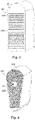
- Figure 3 is shown an embodiment in which there are a plurality of winding layers 222 in each stator slot 221.
- the cooling channel 21 is situated in the bottom of the stator slot 221, the bottom of the stator slot 221 being on the inner yoke of the stator 22 and furthest from the airgap 25 between the rotor 23 and the stator 22, in such a way as to cool directly the last winding layer 222 and core part 225 at the same time.
- the magnetic leakage flux of the electrical machine 2 is considered mainly parallel to the height direction of the stator slot 221 at the bottom of the stator slot 221 wherein the cooling channel 21 is situated.
- the cross-section of the cooling channel 21 has a semi-circular shape.
- This embodiment may suit for a high voltage electrical machine 2, for example.
- This embodiment may suit also in case the stator 22 comprises only one winding layer 222.
- FIG 4 is shown an embodiment in which the cooling channel 21 of the electrical machine 2 is situated in the middle of each stator slot 221 in such a way as to be totally surrounded by the winding layers 222 or winding wires.
- the cross-section of the cooling channel 21 has circular shape.
- the magnetic leakage flux of the electrical machine 2 is considered mainly perpendicular to the height direction of the stator slot 221 in the middle of the stator slot 221 wherein the cooling channel 21 is situated.
- This embodiment may suit for a low voltage electrical machine 2, for example.
- the cooling channel 21 is situated in the core part 225 of the stator 22 in such a way as to be in direct contact only to the core part 225.
- the cooling agent is configured to flow in the cooling channel 21 parallel to the axial direction of the rotor 23.
- the cross-section of the cooling channel 21 has circular shape.
- the placement and shape of the cooling channel 21 in the core part 225 of the stator 2 may differ from what is presented in Figure 5 .
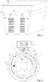
- FIG. 6 illustrates an exemplary structure of an electrical machine 2 and a possible placement of a cooling channel 21 of an electrical machine 2 according to an embodiment.
- the cooling system 1 may comprise at least one connecting channel 12, comprising e.g. a suitable pipe or tube, configured to be connected to the at least one cooling channel 21 of the electrical machine 2.
- the connecting channels 12 may be configured to lead the cooling agent into and out of the electrical machine 2.
- Different kind of structure for the arrangement of the connecting channels 12 may be used depending on e.g. which part of the electrical machine 2 the at least one cooling channel 21 is arranged to.
- the cooling system 1, e.g. the possible connecting channels 12 thereof may be connected to the cooling channel(s) 21 of the electrical machine 2 by suitable connecting means (not shown in the figures), such as pipe or tube connectors, for example.
- the cooling channel 21 is situated between the frame 24 and the stator 22 in such a way as to surround the stator 22.
- the cooling channel 21 is formed between two cylinders having different radius in the radial direction of the stator 22 so as to allow the cooling agent to flow in the cooling channel 21 in circumferential direction of the stator 22.
- the cooling agent is confined only in the region of the stator 22 yoke so that it may not leak towards the airgap 25 of the electrical machine 2.
- This type of cooling channel 21 is defined as a radial cooling channel 21 in this application.
- the cooling agent may take heat from the stator 22 yoke and the upper part of the winding layers 222 and dissipate the heat in the heat exchanger 111.
- This embodiment may suit for a high voltage electrical machine 2 having a high power, for example.
- the placement and size of the radial cooling channel 21 in the stator 2 may differ from what is presented in Figure 6 .
- the at least one cooling channel 21 of the electrical machine 2 is situated at least partially in the rotor 23.
- the rotor 23 comprises a rotor shaft and rotor core 231 having a plurality of rotor slots 232 formed therein, and a plurality of rotor bars comprising rotor windings. Each rotor bar is arranged into a corresponding rotor slot 232.
- the rotor slots 232 are formed as notches on the outer yoke of the rotor 23 in parallel to the axial direction of the rotor shaft.
- Figure 7 is illustrated a sector of a rotor core 231 having rotor slots 232 formed therein.
- the placement of the cooling channels 21 in the rotor 23 differ from what is presented in Figure 7 .
- a method for cooling of an electrical machine 2 comprising at least one cooling channel 21 connected to a cooling system 1, comprises providing a flow of cooling agent through the at least one cooling channel 21 of the electrical machine 2 and the cooling system 1, and cooling the cooling agent in the cooling system 1.
- the cooling agent comprises liquid metal or liquid metal alloy.
- providing the flow of cooling agent is performed by means of the cooling system 1.
- the cooling system 1 may comprise pumping means 14.
- the pumping means 14 cause the cooling agent to flow in a cooling circuit 3 formed of the cooling system 1 and the at least one cooling channel 21.
- the pumping means 14 comprise at least one magnetohydrodynamic pump 141.
- the flow of cooling agent is provided by means of magnetohydrodynamic drive without the use of pumping means 14 as explained later on in this application, or the magnetohydrodynamic drive is exploited in addition to using pumping means 14 for causing the cooling agent to flow.
- the cooling agent is cooled in the cooling system 1 by cooling means 11.
- the cooling means 11 comprise a heat exchanger 111.
- the liquid metal is gallium. According to an embodiment, the liquid metal is mercury, cesium, gallium or rubidium.
- FIG. 1 An example of an embodiment of the method for cooling of an electrical machine 2 is shown in Figure 1 wherein a flow of cooling agent comprising liquid metal or liquid metal alloy is provided through the cooling channel 21 of the electrical machine 2 by means of a magnetohydrodynamic pump 141.
- the cooling system 1 is connected to the cooling channel 21 of the electrical machine 2.
- the cooling agent is cooled in the cooling system 1 by means of a heat exchanger 111.
- the electrical machine 2 is configured to operate as a magnetohydrodynamic pump 141, thereby moving by means of magnetohydrodynamic drive the electrically conductive cooling agent comprising liquid metal or liquid metal alloy through the at least one cooling channel 21 of the electrical machine 2.
- the said magnetohydrodynamic drive is configured to be created as the leakage flux of the electrical machine 2 induces currents in the cooling agent in the cooling channel 21.
- Magnetohydrodynamic drive involves the propulsion of the cooling agent by the Ampere force, resulting from the vector product of an electric current in the cooling agent with a perpendicular magnetic field. In other words, the electric machine acts as magnetohydrodynamic drive and takes the role of a magnetohydrodynamic pump 141.
- the electrical machine 2 utilizes its own electromagnetic field in order to drive the cooling agent without using external power sources such as pumps or blowers, additional energy losses and/or power consumption of external power sources may be avoided.
- the energy spent for the magnetohydrodynamic propulsion of the cooling agent is supplied by the electrical machine 2 itself and may be considered as an electromagnetic loss.
- the electromagnetic leakage flux, typically considered as unwanted in electrical machines 2 may be taken into use in this embodiment.
- the total space, weight and cost of the electrical machine assembly may be reduced. For example, avoiding the need for a blower attached to a rotor shaft may reduce the length and the total mass of the rotor shaft, thereby resulting in better rotor-dynamic behaviour. Noise and vibrations caused by pumps and blowers may be avoided.
- a high power/volume ratio of the electrical machine 2 achieved due to the use of cooling agent comprising liquid metal combined with an ability to operate without any pumps or blowers may make the electrical machine 2 more compact in size and thus attractive especially for applications for limited spaces, such as for electric cars or for other applications related to transportation.
- a direct current may be created in the cooling agent by means of a pair of electrodes set on opposite sides of the cooling channel 21 of the electrical machine 2 as voltage is applied between the electrodes.
- a magnetic field is generated by the electrical machine 2, being a part of the same magnetic field that magnetizes the magnetic circuit of the electrical machine 2.
- the Ampere force acts on the cooling agent in the direction of the cooling channel 21. Due to the force applied, the cooling agent is accelerated along the cooling channel 21 to a certain speed and a forced cooling in the cooling channel 21 is created.
- This kind of magnetohydrodynamic drive is of conduction type.
- the cooling agent is configured to flow in the axial direction of the rotor 23.
- the cooling channel 21 has then a double role: one for cooling and the other one for driving the cooling agent within the cooling circuit 3.
- the driving force created in the cooling channel 21 of the electrical machine 2 moves the cooling agent towards the cooling means 11, such as a heat exchanger 111, where the cooling agent is cooled and the cooling agent is recirculated again into the electrical machine 2.
- Magnetohydrodynamic drive may be exploited in the cooling channels 21 of the electrical machine 2 where there is a presence of a magnetic field.
- the cooling channels 21 may be placed nearly in any part of the electrical machine 2, most preferably close to the at least one winding layer 222 of the stator 22, into the stator slots 221 as presented especially in Figures 2 - 4 , wherein the magnetic field used in generation of the magnetohydrodynamic drive is the magnetic leakage flux in each stator slot 221.
- the direction of the magnetic leakage flux is explained earlier in this application in relation to each embodiment.
- the magnetic field used in generation of the magnetohydrodynamic drive is the magnetic leakage flux in the cooling channel 21.
- Conduction type of magnetohydrodynamic drive may be therefore most suitable in parts of the electrical machine 2 that have a constant and unidirectional magnetic field such as a stator 22 of a direct current electrical machine and a rotor 23 of a synchronous machine.
- the direction of the current should be synchronized with the direction of the magnetic field by using electronic components.
- induction type of magnetohydrodynamic drive the alternating currents are induced by a varying magnetic field, as eddy currents.
- a varying magnetic field as the rotor 23 of the electrical machine 2 rotates at angular speed ⁇ r and there is a rotational magnetic field in the stator 22, some part of the magnetic flux penetrates as a leakage flux into the radial cooling channel 21 inducing currents in the cooling agent and, as a result, creates a moment that moves the cooling agent with angular speed ⁇ ca .
- the moment that accelerates the cooling agent acts on the whole circumference of the stator 22, and the whole cooling channel 21 acts as an induction magnetohydrodynamic pump 141.
- Electrodes and/or auxiliary electronic components are not required for synchronization of the direction of the electrical current of the cooling agent with the direction of the magnetic field. Consequently, this type of magnetohydrodynamic drive is more convenient in electrical machines 2 of alternating current.
- the induction type of magnetohydrodynamic drive may also be used in association with the embodiment explained above related to Figure 5 , for example, by skewing the cooling channel 21 of the electrical machine 2 by a certain angle ⁇ in such a way that the direction of the cooling channel 21 differs from the axial direction of the rotor 23 by that angle ⁇ .
- An example of a skewed cooling channel 21 is shown in Figure 8 .
- a force F acts on the electrically conductive cooling agent in the cooling channel 21.
- One way to make the effect of skewing on the stator core may be by punching the opening for the cooling channels 21 on each lamination of the stator with a small angular step for each following lamination, in case the stator comprises a plurality of laminations, for example. Due to the skewed cooling channels 2, the current is created in the cooling agent without the use of electrodes.
Landscapes
- Engineering & Computer Science (AREA)
- Power Engineering (AREA)
- Motor Or Generator Cooling System (AREA)
Abstract
An electrical machine assembly and a method for cooling of an electrical machine, the electrical machine assembly comprising an electrical machine (2), a cooling system (1) and cooling agent. The electrical machine (2) comprises at least one cooling channel (21) arranged therein. The cooling system (1) is connected to the at least one cooling channel (21) of the electrical machine (2). The cooling system (1) and the at least one cooling channel (21) of the electrical machine (2) form a cooling circuit (3). There is cooling agent comprising liquid metal or liquid metal alloy within the cooling circuit (3).
Description
- The present invention relates to an electrical machine assembly and to a method for cooling of an electrical machine.
- An electrical machine may be a rotating machine comprising a rotor and a stator, such as a motor or a generator, for example. This type of electrical machine may be generally configured for conversion between mechanical energy and electrical energy. Also, transformers are an example of electrical machines.
- Electrical machines may be cooled with gaseous or liquid cooling agent, such as air or water, for example. An electrical machine assembly may comprise an electrical machine, a cooling system and cooling agent, for example. In case of cooling with a liquid cooling agent, the electrical machine may for instance comprise cooling channels connected to the cooling system. A cooling circuit may be formed of the cooling channels of the electrical machine and the cooling system.
- A problem associated with the above solution is that the cooling of the electrical machine may not be efficient enough. Especially, this may be the case with electrical machines having high power/volume ratios.
- An object of the present invention is to provide a method and an apparatus for implementing the method so as to solve the above disadvantage or at least to alleviate the above disadvantage. The object of the invention is achieved by an electrical machine assembly and a method which are characterized by what is stated in the independent claims. The preferred embodiments of the invention are disclosed in the dependent claims.
- The invention is based on an idea of providing an electrical machine assembly, wherein the cooling agent within the cooling circuit comprises liquid metal or liquid metal alloy.
- An advantage provided by the solution of the invention is that cooling of the electrical machine is more efficient.
- In the following the invention will be described in greater detail by means of preferred embodiments with reference to the accompanying drawings, in which
-
Figure 1 illustrates an example of an electrical machine assembly according to an embodiment; -
Figure 2 illustrates a placement of a cooling channel of an electrical machine according to an embodiment; -
Figure 3 illustrates a placement of a cooling channel of an electrical machine according to an embodiment; -
Figure 4 illustrates a placement of a cooling channel of an electrical machine according to an embodiment; -
Figure 5 illustrates a placement of a cooling channel of an electrical machine according to an embodiment; -
Figure 6 illustrates a structure of an electrical machine and a placement of a cooling channel of an electrical machine according to an embodiment; -
Figure 7 illustrates a placement of cooling channels of an electrical machine according to an embodiment; and -
Figure 8 illustrates a skewed cooling channel of an electrical machine according to an embodiment. - The following embodiments are exemplary. Although the description may refer to "an", "one", or "some" embodiment(s) in several locations, this does not necessarily mean that each such reference is to the same embodiment(s), or that the feature only applies to a single embodiment, for example. Single features of different embodiments may also be combined to provide other embodiments. Generally, all terms and expressions used should be interpreted broadly and they are intended to illustrate, not to restrict, the embodiments. The figures only show components necessary for understanding the various embodiments. The number and/or shape of the various elements, and generally their implementation, could vary from the examples shown in the figures.
- According to an embodiment, an electrical machine assembly comprises an electrical machine, a cooling system and cooling agent. The electrical machine comprises at least one cooling channel arranged therein. The cooling system is connected to the at least one cooling channel of the electrical machine. The cooling system and the at least one cooling channel of the electrical machine form a cooling circuit. There is cooling agent within the cooling circuit. The cooling agent comprises liquid metal or liquid metal alloy. Term liquid metal (alloy) generally refers to a metal (alloy) which is liquid at or near room temperature; e.g. at temperatures below about 40 °C. Such liquid metals are for example mercury, cesium, gallium and rubidium. The melting point for mercury is -38.9 °C, for cesium 28.7 °C, for gallium 29.8 °C and for rubidium 38.9 °C.
-
Figure 1 illustrates an example of an electrical machine assembly according to an embodiment, described as a conceptual drawing. The electrical machine assembly according toFigure 1 comprises anelectrical machine 2 comprising at least onecooling channel 21 arranged therein. Theelectrical machine 2 may be a rotating machine such as a motor or a generator, for example. - In some alternative exemplary embodiments, the number of the
electrical machines 2 in the assembly as well as their type and construction may vary. The arrangement of the at least onecooling channel 21 in theelectrical machine 2 may also vary. Theelectrical machine 2 may comprise a plurality ofcooling channels 21. - As shown in
Figure 1 , thecooling system 1 is connected to thecooling channel 21 of theelectrical machine 2 in such a way that thecooling system 1 and the at least onecooling channel 21 of theelectrical machine 2 form acooling circuit 3. Thecooling circuit 3 may be a closed circuit. In some alternative exemplary embodiments, the construction of thecooling system 1 and thecooling circuit 3 may vary. - In the electrical machine assembly, there is cooling agent within the
cooling circuit 3. The cooling agent is configured to flow in a closed cycle in thecooling circuit 3. The cooling agent comprises liquid metal or liquid metal alloy. - Thermal conductivity of liquid metals may be higher compared to traditionally used cooling agents such as air and water, for instance. Consequently, the cooling agent comprising liquid metal or liquid metal alloy may have a higher cooling capacity compared to the said traditional cooling agents. Liquid metal to be used as cooling agent advantageously has good cooling properties, especially high thermal conductivity, high thermal capacity and low viscosity. The temperature range in which the liquid metal remains in a liquid state should preferably cover the operating temperature range of components of the
electrical machine 2 to be cooled. This temperature range may generally be between ambient temperature and 150 °C, for example depending on the machine in question. Thus, the liquid metal used should preferably have low enough melting point and high enough boiling point. For not setting too high demands for the design of thecooling system 1, the vapor pressure of the liquid metal should preferably be low enough. The liquid metal should preferably have adequate electrical conductivity, enabling it to be pumped with an electromagnetic pump into theelectrical machine 2, for example. In alternative exemplary embodiments, any type of pump that causes the cooling agent to flow in thecooling circuit 3 may be used. The technical properties of the liquid metal may further preferably support a low probability of leakage of the cooling agent. In addition, the liquid metal to be used as cooling agent may preferably be cost effective. In addition to technical preconditions, the liquid metal may preferably fulfil safety demands, e.g. as being nontoxic, non-flammable, environmentally friendly and/or having low emission of vapor, for example. - To show an example, the cooling properties of some liquid metals are listed in Table 1. Metals like potassium, sodium, indium, lithium and thin may have quite low melting points but they are above the standard ambient temperature. For example, mercury, cesium, gallium and rubidium are in a liquid state at temperatures lower or close to the standard ambient temperature of 40 °C. The cooling properties listed in Table 1 are shown for pure liquid metals. Some physical properties may be improved by using alloys of liquid metals, especially for reducing the melting point or improving the thermal conductivity, for example.
Table 1. Cooling properties of some liquid metals (a) 25 °C; b) 100 °C; c) 50°C; d) 40 °C; e) 77°C). Cooling agent Melting point [°C] Boiling point [°C] Evaporation pressure [mmHg] Specific heat D/kgK] Density [kg/m3] Thermal conductivity [W/mK] Dynamic viscosity [Pa s] Mercury -38.9 356.7 1.68* 10-3 a) 139 a) 13546 a) 8.3 a) 0.00155 a) Cesium 28.7 2023.8 10-6 b) 236 b) 1796b) 17.4b) 0.000334 b) Gallium 29.8 2204.8 10-12 370 c) 5907 c) 29.4 c) 0.001369 e) Rubidium 38.9 685.7 6*10-6 363 d) 1470 d) 29.3 d) 0.000671 d) - As may be seen from Table 1, mercury has the lowest melting point, but the rest of the liquid metals may also have low enough melting points to be used as cooling agents for an electrical machine, for instance. Some liquid metals may be kept at liquid state at lower temperatures than the melting points due to the undercooling point. For example, once gallium is already in a liquid state, gallium may be kept as liquid at a temperature down to about 1 °C. Gallium may remain at liquid state at normal room temperatures, for example. The boiling point of each liquid metals listed in Table 1 is higher than the boiling point of the water (100 °C), for example. This may be beneficial for direct cooling of parts of the electrical machine whose temperature may exceed the boiling point of water, for example. The liquid metal may stay as single-phase fluid, avoiding abrupt changes of pressure while flowing. The coefficient of thermal conductivity of each liquid metal listed in Table 1 is higher than that of water (0.6 W/mK), for example. Gallium has the highest coefficient of thermal conductivity of the metals listed in Table 1 which is about 50 times higher than that of water, for example. Although gallium has about 11 times lower specific heat capacity than water (4200 J/kgK), due to the higher mass density of gallium, the specific heat per unit volume of gallium is only about half of that of water, i.e. 4200 kJ/(m3K) for water and 2186 kJ/(m3K) for liquid gallium, for example. Gallium has higher specific heat than the rest of the liquid metals listed in Table 1, for instance.
- Although any of the liquid metals listed on Table 1 may have superior cooling properties compared to water, the health and environmental demands may also be considered. For example, mercury may be considered as toxic. Mercury has higher vapor pressure than other liquid metals listed in Table 1, for example. Consequently, when mercury is used as a cooling agent, a leakage of mercury from the cooling system may cause serious contamination even at a room temperature, and the situation may be worse at higher temperatures, for example. Cesium and Rubidium may also have good cooling properties but belonging to the group of alkali metals, they may be chemically highly reactive with oxygen and water, for instance. Gallium may be considered as relatively nontoxic. Gallium may be safe for the human skin. Gallium may also be nonreactive with water, especially at temperatures below 100 °C. Gallium has very low vapor pressure which may be advantageous regarding safe use in a closed cooling system, for example.
- According to an embodiment, liquid metal comprised in the cooling agent is gallium or gallium alloy. Gallium has high thermal conductivity, high volume specific heat, wide working temperature range and very low vapor pressure which are advantageous features for a liquid metal to be used as cooling agent for
electrical machines 2. In addition, gallium is relatively nontoxic and not dangerous for the environment, thus fulfilling the environmental and health standards. - Here is presented an exemplary comparison between the cooling capabilities of liquid gallium and water.
- Reynolds number, showing the degree of turbulence of a fluid, for circular channel may be calculated as follows:

- The degree of turbulence is defined as follows:
- Re < 2300: fully laminar flow
- 2300 < Re < 10000: transient flow, partly laminar and partly turbulent properties and
- 10000 < Re: fully turbulent flow.
- Considering:
- a circular cooling channel with diameter of Dc=1 cm, wherein cooling agent moves with axial speed Vax=0.1m/s,
- dynamic viscosity µ 1.369*10-3 Pa s for gallium (at 77 °C) and 8.9* 10-4 Pa s for water (at 25 °C) and
- density ρ 5907 kg/m3 for gallium (at 50 °C) and 1000 kg/m3 for water,
- A laminar water flow in a circular tube characterized by uniform surface heat flux and fully developed conditions has a constant Nusselt number Nuw = 4.36.
- Prandtl number is Prlg = 0.025 for liquid gallium and Prw = 7.56 for water.
- The Nusselt number for liquid metals is calculated as follows:

- For liquid gallium flow Nusselt number is Nulg = 5.71.
- Coefficient of thermal convection is calculated as follows:

- Coefficient of thermal convection is hlg = 16 787 W/m2K for liquid gallium and hw = 262 W/m2K for water.
- As may be seen, considering the same conditions for cooling, the liquid gallium flow may achieve up to 64 times higher coefficient of convection than the water flow, for example. Cooling properties of gallium seem superior compared to water, for instance.
- Using liquid gallium in convective cooling of an
electrical machine 2 may provide a drastic enhancement in cooling efficiency. Improving cooling efficiency also enables to increase the nominal power and/or reduce dimensions of theelectrical machine 2. Theelectrical machine 2 cooled by liquid metal may have a better power/volume ratio in comparison with a traditionalelectrical machine 2 cooled by air or water. - Liquid gallium may possess somewhat better properties for a cooling agent compared to some other liquid metals, for example. In some alternative exemplary embodiments, the liquid metal that may be used as a cooling agent may be mercury, cesium, gallium or rubidium, for example, or an alloy of any one of them or a combination of two or more of them. The liquid metal alloy may comprise copper in addition to gallium, for example.
- Inside the electrical machine, the high or medium frequency magnetic fields may cause electromagnetic losses in cooling agent comprising liquid metal of liquid metal alloy as the cooling agent is electrically conductive.
- According to an embodiment, the cooling agent comprises particles of at least one electrically insulating material. The particles of at least one insulating material may be of micro or nano size, for example.
- According to an embodiment, the at least one insulating material comprises diamond, silicon and/or ceramics. Adding small particles of insulating material such as silicon and/or ceramics to the cooling agent comprising liquid metal or liquid metal alloy may enable to reduce electromagnetic losses in the cooling agent inside the
electrical machine 2. This is beneficial as far as the overall thermal conductivity of the cooling agent may not be compromised. The most preferable option may be to use diamond particles. Since diamond may be considered as both an excellent thermal conductor and an electrical insulator, adding diamond particles to the cooling agent may reduce electrical conductivity and improve thermal conductivity of the liquid metal at the same time. In other words, the electromagnetic losses of the cooling agent may be limited and the overall cooling effect of the cooling agent may be improved at the same time. - According to an embodiment shown in
Figure 1 , thecooling system 1 comprises cooling means 11 configured to cool the cooling agent. According to an embodiment, the cooling means 11 comprise aheat exchanger 111 configured to dissipate heat from the cooling agent to the ambient. - According to an embodiment shown in
Figure 1 , thecooling system 1 comprises pumping means 14 configured to cause the cooling agent to flow in thecooling circuit 3. According to an embodiment, the pumping means 14 comprise at least one electromagnetic pump ormagnetohydrodynamic pump 141. Liquid gallium and other liquid metals have relatively good electrical conductivity that enables the usage of amagnetohydrodynamic pump 141 for driving the liquid metal in thecooling circuit 3 of the electrical machine assembly. Using amagnetohydrodynamic pump 141 is beneficial especially due to high efficiency, low energy consumption, silent and vibration-free operation and usage of non-moving parts only. - In alternative exemplary embodiments, the pumping means 14 comprise a peristaltic pump and/or electro-wetting pump. In alternative exemplary embodiments, the pumping means 14 comprise a traditional pump for example when the electrical conductivity of the cooling agent is not high enough for using a
magnetohydrodynamic pump 141. - According to an embodiment, the cooling
channels 21 may be arranged in thermally critical parts of theelectrical machine 2 unlike in traditionally cooledelectrical machines 2 in which thecooling channels 21 are typically arranged on the outer surface of theelectrical machine 2 as a so called water jacket, for example. According to an embodiment, the coolingchannels 21 of theelectrical machine 2 may be arranged to cool very hot parts of theelectrical machine 2 such as near the windings. Temperature at this kind of very hot parts of theelectrical machine 2 may exceed the boiling point of water but not the boiling point of liquid metal or liquid metal alloy. - Compared to
traditional cooling channels 21 used for example with air cooling of anelectrical machines 2, the coolingchannels 21 according to an embodiment may be of lower volume due to the superior cooling properties of liquid metal. In other words, extracting heat from highly confined space of theelectrical machine 2 is more effective using liquid metal or liquid metal alloy as cooling agent. - The electromagnetic losses that may be generated in the liquid metal inside the
electrical machine 2 may be avoided or limited by a proper choice of the location of coolingchannels 21 of theelectrical machine 2. The positioning of thecooling channels 21 may be selected so as to avoid high-leakage flux penetrating the cooling agent comprising liquid metal or liquid metal alloy, for example. - In some exemplary embodiments, the cooling
channels 21 of theelectrical machine 2 may be placed to traditionally used places. - According to an embodiment as illustrated in
Figure 6 , theelectrical machine 2 is a rotating machine comprising aframe 24, arotor 23 and astator 22 situated inside theframe 24 and surrounding therotor 23. Therotor 23 is configured to rotate in relation to thestator 22. There is anairgap 25 between therotor 23 and thestator 22. - According to an embodiment, the at least one
cooling channel 21 of theelectrical machine 2 is situated at least partially in thestator 22 and/or in theframe 24.Figures 2 - 6 illustrate exemplary embodiments of possible placements of coolingchannels 21 in thestator 22. In some alternative exemplary embodiments, theelectrical machine 2 comprises a plurality ofcooling channels 21, the placement of which may combine the embodiments illustrated in the Figures or differ from them. Also, the shape of coolingchannels 21 may differ from what is presented in the Figures. For instance, there may be a plurality ofcooling channels 21 in the frame 24 (not shown in Figures). - According to an embodiment, the
electrical machine 2 comprises a plurality ofcooling channels 21, and thestator 22 of theelectrical machine 2 comprises acore part 225 having a plurality ofstator slots 221 formed therein, and at least one windinglayer 222 arranged in eachstator slot 221. - According to an embodiment, each
stator slot 221 and/or thecore part 225 has at least onecooling channel 21 at least partly situated therein. Thus, each of thestator slots 221 may have one or morededicated cooling channels 21 located to pass through therespective stator slot 221. It is also possible that onecooling channel 21 passes through two or moredifferent stator slots 221, for instance. Thecore part 225 of thestator 22 surrounds therotor 23 in such a way that thestator slots 221 are formed as notches on the inner yoke of thestator 22, in other words on the inner perimeter of thecylindrical stator 22 yoke, closest to therotor 23. The amount and shape of thestator slots 221 may vary according to the type of theelectrical machine 2. Eachstator slot 221 has a length direction parallel to the axial direction of therotor 23 and a height direction parallel to radial direction of therotor 23. - The embodiments of
Figures 2 - 4 illustrate different options of how to place a coolingchannel 21 into astator slot 221, describing only onestator slot 221 of the plurality of thestator slots 221 of theelectrical machine 2. As the at least one windinglayer 222, including its insulation, may be the most thermally critical part of theelectrical machine 2, a very effective way to cool it may be placing thecooling channels 21, or at least some of them, directly inside thestator slots 221. The cooling agent is configured to flow in each coolingchannel 21 at least principally in a direction parallel to the axial direction of therotor 23, in other words in a direction parallel to the length direction of thestator slots 221. - According to an embodiment, the
stator 22 comprises at least two windinglayers 222, and the at least onecooling channel 21 of theelectrical machine 2 is situated between the winding layers 222. InFigure 2 is shown an embodiment in which thestator 22 comprises a plurality of windinglayers 222 arranged in thestator slot 221 wherein the coolingchannel 21 is situated between the windinglayers 222 in eachstator slot 221. The coolingchannel 21 may be placed e.g. approximately in the middle of thestator slot 221 in its height direction as illustrated in the example. The magnetic leakage flux of theelectrical machine 2 is considered mainly perpendicular to the height direction of thestator slot 221 in the middle of thestator slot 221 wherein the coolingchannel 21 is situated. The cross-section of the coolingchannel 21 is of rectangular shape. Also, the cross-section of thestator slot 221 is substantially rectangular in shape. This shape of thestator slot 221 may be typical in high-voltageelectrical machines 2. This embodiment may suit for a high voltageelectrical machine 2, for example. - According to an embodiment, the at least one
cooling channel 21 of theelectrical machine 2 is situated in an edge of eachstator slot 221 or in a bottom of eachstator slot 221. InFigure 3 is shown an embodiment in which there are a plurality of windinglayers 222 in eachstator slot 221. The coolingchannel 21 is situated in the bottom of thestator slot 221, the bottom of thestator slot 221 being on the inner yoke of thestator 22 and furthest from theairgap 25 between therotor 23 and thestator 22, in such a way as to cool directly the last windinglayer 222 andcore part 225 at the same time. The magnetic leakage flux of theelectrical machine 2 is considered mainly parallel to the height direction of thestator slot 221 at the bottom of thestator slot 221 wherein the coolingchannel 21 is situated. The cross-section of the coolingchannel 21 has a semi-circular shape. This embodiment may suit for a high voltageelectrical machine 2, for example. This embodiment may suit also in case thestator 22 comprises only one windinglayer 222. - In
Figure 4 is shown an embodiment in which the coolingchannel 21 of theelectrical machine 2 is situated in the middle of eachstator slot 221 in such a way as to be totally surrounded by the windinglayers 222 or winding wires. The cross-section of the coolingchannel 21 has circular shape. The magnetic leakage flux of theelectrical machine 2 is considered mainly perpendicular to the height direction of thestator slot 221 in the middle of thestator slot 221 wherein the coolingchannel 21 is situated. This embodiment may suit for a low voltageelectrical machine 2, for example. - In the embodiment shown in
Figure 5 , the coolingchannel 21 is situated in thecore part 225 of thestator 22 in such a way as to be in direct contact only to thecore part 225. The cooling agent is configured to flow in the coolingchannel 21 parallel to the axial direction of therotor 23. The cross-section of the coolingchannel 21 has circular shape. In alternative exemplary embodiments, the placement and shape of the coolingchannel 21 in thecore part 225 of thestator 2 may differ from what is presented inFigure 5 . -
Figure 6 illustrates an exemplary structure of anelectrical machine 2 and a possible placement of a coolingchannel 21 of anelectrical machine 2 according to an embodiment. According to an embodiment, thecooling system 1 may comprise at least one connectingchannel 12, comprising e.g. a suitable pipe or tube, configured to be connected to the at least onecooling channel 21 of theelectrical machine 2. As shown in the exemplary embodiment inFigure 6 , the connectingchannels 12 may be configured to lead the cooling agent into and out of theelectrical machine 2. Different kind of structure for the arrangement of the connectingchannels 12 may be used depending on e.g. which part of theelectrical machine 2 the at least onecooling channel 21 is arranged to. Thecooling system 1, e.g. the possible connectingchannels 12 thereof, may be connected to the cooling channel(s) 21 of theelectrical machine 2 by suitable connecting means (not shown in the figures), such as pipe or tube connectors, for example. - According to an embodiment shown in
Figure 6 , the coolingchannel 21 is situated between theframe 24 and thestator 22 in such a way as to surround thestator 22. The coolingchannel 21 is formed between two cylinders having different radius in the radial direction of thestator 22 so as to allow the cooling agent to flow in the coolingchannel 21 in circumferential direction of thestator 22. In other words, the cooling agent is confined only in the region of thestator 22 yoke so that it may not leak towards theairgap 25 of theelectrical machine 2. This type of coolingchannel 21 is defined as aradial cooling channel 21 in this application. When the cooling agent flows circumferentially, the cooling agent may take heat from thestator 22 yoke and the upper part of the windinglayers 222 and dissipate the heat in theheat exchanger 111. This embodiment may suit for a high voltageelectrical machine 2 having a high power, for example. In alternative exemplary embodiments, the placement and size of theradial cooling channel 21 in thestator 2 may differ from what is presented inFigure 6 . - According to an embodiment, the at least one
cooling channel 21 of theelectrical machine 2 is situated at least partially in therotor 23. Therotor 23 comprises a rotor shaft androtor core 231 having a plurality ofrotor slots 232 formed therein, and a plurality of rotor bars comprising rotor windings. Each rotor bar is arranged into acorresponding rotor slot 232. Therotor slots 232 are formed as notches on the outer yoke of therotor 23 in parallel to the axial direction of the rotor shaft. InFigure 7 is illustrated a sector of arotor core 231 havingrotor slots 232 formed therein. There are coolingchannels 21 situated inrotor core 231 in parallel to the direction of therotor slots 232. In alternative exemplary embodiments, the placement of thecooling channels 21 in therotor 23 differ from what is presented inFigure 7 . - According to an embodiment, a method for cooling of an
electrical machine 2 comprising at least onecooling channel 21 connected to acooling system 1, comprises providing a flow of cooling agent through the at least onecooling channel 21 of theelectrical machine 2 and thecooling system 1, and cooling the cooling agent in thecooling system 1. The cooling agent comprises liquid metal or liquid metal alloy. The method described herein is applicable to all embodiments described herein related different kinds of electrical machine assemblies. - According to an embodiment, providing the flow of cooling agent is performed by means of the
cooling system 1. Thecooling system 1 may comprise pumping means 14. According to an embodiment, the pumping means 14 cause the cooling agent to flow in acooling circuit 3 formed of thecooling system 1 and the at least onecooling channel 21. According to an embodiment, the pumping means 14 comprise at least onemagnetohydrodynamic pump 141. According to an embodiment, the flow of cooling agent is provided by means of magnetohydrodynamic drive without the use of pumping means 14 as explained later on in this application, or the magnetohydrodynamic drive is exploited in addition to using pumping means 14 for causing the cooling agent to flow. - According to an embodiment, the cooling agent is cooled in the
cooling system 1 by cooling means 11. According to an embodiment, the cooling means 11 comprise aheat exchanger 111. - According to an embodiment, the liquid metal is gallium. According to an embodiment, the liquid metal is mercury, cesium, gallium or rubidium.
- An example of an embodiment of the method for cooling of an
electrical machine 2 is shown inFigure 1 wherein a flow of cooling agent comprising liquid metal or liquid metal alloy is provided through the coolingchannel 21 of theelectrical machine 2 by means of amagnetohydrodynamic pump 141. Thecooling system 1 is connected to the coolingchannel 21 of theelectrical machine 2. The cooling agent is cooled in thecooling system 1 by means of aheat exchanger 111. - According to an embodiment, the
electrical machine 2 is configured to operate as amagnetohydrodynamic pump 141, thereby moving by means of magnetohydrodynamic drive the electrically conductive cooling agent comprising liquid metal or liquid metal alloy through the at least onecooling channel 21 of theelectrical machine 2. The said magnetohydrodynamic drive is configured to be created as the leakage flux of theelectrical machine 2 induces currents in the cooling agent in the coolingchannel 21. Magnetohydrodynamic drive involves the propulsion of the cooling agent by the Ampere force, resulting from the vector product of an electric current in the cooling agent with a perpendicular magnetic field. In other words, the electric machine acts as magnetohydrodynamic drive and takes the role of amagnetohydrodynamic pump 141. - As the
electrical machine 2 utilizes its own electromagnetic field in order to drive the cooling agent without using external power sources such as pumps or blowers, additional energy losses and/or power consumption of external power sources may be avoided. The energy spent for the magnetohydrodynamic propulsion of the cooling agent is supplied by theelectrical machine 2 itself and may be considered as an electromagnetic loss. The electromagnetic leakage flux, typically considered as unwanted inelectrical machines 2, may be taken into use in this embodiment. The total space, weight and cost of the electrical machine assembly may be reduced. For example, avoiding the need for a blower attached to a rotor shaft may reduce the length and the total mass of the rotor shaft, thereby resulting in better rotor-dynamic behaviour. Noise and vibrations caused by pumps and blowers may be avoided. - A high power/volume ratio of the
electrical machine 2 achieved due to the use of cooling agent comprising liquid metal combined with an ability to operate without any pumps or blowers may make theelectrical machine 2 more compact in size and thus attractive especially for applications for limited spaces, such as for electric cars or for other applications related to transportation. - In the embodiments explained above related to
Figures 2 - 5 , a direct current may be created in the cooling agent by means of a pair of electrodes set on opposite sides of the coolingchannel 21 of theelectrical machine 2 as voltage is applied between the electrodes. A magnetic field is generated by theelectrical machine 2, being a part of the same magnetic field that magnetizes the magnetic circuit of theelectrical machine 2. The Ampere force acts on the cooling agent in the direction of the coolingchannel 21. Due to the force applied, the cooling agent is accelerated along the coolingchannel 21 to a certain speed and a forced cooling in the coolingchannel 21 is created. This kind of magnetohydrodynamic drive is of conduction type. As the coolingchannel 21 is of an axial type, the cooling agent is configured to flow in the axial direction of therotor 23. The coolingchannel 21 has then a double role: one for cooling and the other one for driving the cooling agent within thecooling circuit 3. The driving force created in the coolingchannel 21 of theelectrical machine 2 moves the cooling agent towards the cooling means 11, such as aheat exchanger 111, where the cooling agent is cooled and the cooling agent is recirculated again into theelectrical machine 2. - Magnetohydrodynamic drive may be exploited in the
cooling channels 21 of theelectrical machine 2 where there is a presence of a magnetic field. In this regard, the coolingchannels 21 may be placed nearly in any part of theelectrical machine 2, most preferably close to the at least one windinglayer 222 of thestator 22, into thestator slots 221 as presented especially inFigures 2 - 4 , wherein the magnetic field used in generation of the magnetohydrodynamic drive is the magnetic leakage flux in eachstator slot 221. The direction of the magnetic leakage flux is explained earlier in this application in relation to each embodiment. As toFigure 5 , the magnetic field used in generation of the magnetohydrodynamic drive is the magnetic leakage flux in the coolingchannel 21. - The vector product of the current and the magnetic field should result in a force only in one direction in order to create a constant movement of the flow in one direction. Consequently, an eventual change in the direction of the magnetic field should be followed by a change in the direction of the electrical current. Conduction type of magnetohydrodynamic drive may be therefore most suitable in parts of the
electrical machine 2 that have a constant and unidirectional magnetic field such as astator 22 of a direct current electrical machine and arotor 23 of a synchronous machine. In order to utilize the effect of conduction type of magnetohydrodynamic drive in parts of theelectrical machines 2 with alternating magnetic field, the direction of the current should be synchronized with the direction of the magnetic field by using electronic components. - In induction type of magnetohydrodynamic drive the alternating currents are induced by a varying magnetic field, as eddy currents. In the embodiment explained above related to
Figure 6 , as therotor 23 of theelectrical machine 2 rotates at angular speed ωr and there is a rotational magnetic field in thestator 22, some part of the magnetic flux penetrates as a leakage flux into theradial cooling channel 21 inducing currents in the cooling agent and, as a result, creates a moment that moves the cooling agent with angular speed ωca. The moment that accelerates the cooling agent acts on the whole circumference of thestator 22, and thewhole cooling channel 21 acts as an inductionmagnetohydrodynamic pump 141. Electrodes and/or auxiliary electronic components are not required for synchronization of the direction of the electrical current of the cooling agent with the direction of the magnetic field. Consequently, this type of magnetohydrodynamic drive is more convenient inelectrical machines 2 of alternating current. - According to an embodiment, the induction type of magnetohydrodynamic drive may also be used in association with the embodiment explained above related to
Figure 5 , for example, by skewing the coolingchannel 21 of theelectrical machine 2 by a certain angle θ in such a way that the direction of the coolingchannel 21 differs from the axial direction of therotor 23 by that angle θ. An example of a skewedcooling channel 21 is shown inFigure 8 . In case of having a rotating magnetic field with angular velocity ω, due to the effect of induction, a force F acts on the electrically conductive cooling agent in the coolingchannel 21. As the coolingchannel 21 is skewed, a force component F1=F ∗ sin θ moves the cooling agent along the coolingchannel 21. The higher the angle θ of skewing, the higher the force component F1 acting on the cooling agent. One way to make the effect of skewing on the stator core may be by punching the opening for thecooling channels 21 on each lamination of the stator with a small angular step for each following lamination, in case the stator comprises a plurality of laminations, for example. Due to the skewedcooling channels 2, the current is created in the cooling agent without the use of electrodes. - It will be obvious to a person skilled in the art that the inventive concept can be implemented in various ways. The invention and its embodiments are not limited to the examples described above but may vary within the scope of the claims.
Claims (15)
- An electrical machine assembly, comprising:an electrical machine (2) comprising at least one cooling channel (21) arranged therein;a cooling system (1) connected to the at least one cooling channel (21) of the electrical machine (2), wherein the cooling system (1) and the at least one cooling channel (21) of the electrical machine (2) form a cooling circuit (3); andcooling agent within the cooling circuit (3), wherein the cooling agent comprises liquid metal or liquid metal alloy.
- An electrical machine assembly according to claim 1, wherein the liquid metal is gallium.
- An electrical machine assembly according to claim 1 or 2, wherein the cooling agent comprises particles of at least one electrically insulating material.
- An electrical machine assembly according claim 3, wherein the at least one electrically insulating material comprises diamond, silicon and/or ceramics.
- An electrical machine assembly according to any one of the previous claims, wherein the cooling circuit (3) is a closed circuit.
- An electrical machine assembly according to any one of the previous claims, wherein the cooling system (1) comprises cooling means (11) configured to cool the cooling agent.
- An electrical machine assembly according to any one of the previous claims, wherein the electrical machine (2) is a rotating machine comprising:a frame (24);a rotor (23); anda stator (22) situated inside the frame (24) and surrounding the rotor (23).
- An electrical machine assembly according to claim 7, wherein the at least one cooling channel (21) of the electrical machine (2) is situated at least partly in the stator (22) and/or in the frame (24).
- An electrical machine assembly according to claim 7 or claim 8, wherein the at least one cooling channel (21) of the electrical machine (2) is situated at least partly in the rotor (23).
- An electrical machine assembly according to any one of claims 7 - 9, wherein the electrical machine (2) comprises a plurality of cooling channels (21), and the stator (22) of the electrical machine (2) comprises a core part (225) having a plurality of stator slots (221) formed therein, and at least one winding layer (222) arranged in each stator slot (221), and wherein each stator slot (221) and/or the core part (225) has at least one cooling channel (21) at least partly situated therein.
- An electrical machine assembly according to claim 10, wherein the at least one cooling channel (21) of the electrical machine (2) is situated in the edge of each stator slot (221) or in the bottom of each stator slot (221).
- An electrical machine assembly according to claim 10 or claim 11, wherein the stator (22) comprises at least two winding layers (222), and the at least one cooling channel (21) of the electrical machine (2) is situated between the winding layers (222).
- An electrical machine assembly according any one of the previous claims, wherein the electrical machine (2) is configured to operate as a magnetohydrodynamic pump.
- An electrical machine assembly according any one of the previous claims, wherein the cooling system (1) comprises pumping means (14) configured to cause the cooling agent to flow in the cooling circuit (3).
- A method for cooling of an electrical machine (2), the electrical machine (2) comprising at least one cooling channel (21) connected to a cooling system (1), the method comprising:providing a flow of cooling agent through the at least one cooling channel (21) of the electrical machine (2) and the cooling system (1), wherein the cooling agent comprises liquid metal or liquid metal alloy; andcooling the cooling agent in the cooling system (1).
Priority Applications (1)
| Application Number | Priority Date | Filing Date | Title |
|---|---|---|---|
| EP21178499.6A EP4102691A1 (en) | 2021-06-09 | 2021-06-09 | Electrical machine assembly and method for cooling of electrical machine |
Applications Claiming Priority (1)
| Application Number | Priority Date | Filing Date | Title |
|---|---|---|---|
| EP21178499.6A EP4102691A1 (en) | 2021-06-09 | 2021-06-09 | Electrical machine assembly and method for cooling of electrical machine |
Publications (1)
| Publication Number | Publication Date |
|---|---|
| EP4102691A1 true EP4102691A1 (en) | 2022-12-14 |
Family
ID=76355380
Family Applications (1)
| Application Number | Title | Priority Date | Filing Date |
|---|---|---|---|
| EP21178499.6A Withdrawn EP4102691A1 (en) | 2021-06-09 | 2021-06-09 | Electrical machine assembly and method for cooling of electrical machine |
Country Status (1)
| Country | Link |
|---|---|
| EP (1) | EP4102691A1 (en) |
Cited By (3)
| Publication number | Priority date | Publication date | Assignee | Title |
|---|---|---|---|---|
| CN118457272A (en) * | 2024-07-11 | 2024-08-09 | 比亚迪股份有限公司 | Electric drive assembly, vehicle control method, and vehicle |
| EP4611219A1 (en) * | 2024-02-29 | 2025-09-03 | General Electric Technology GmbH | Electric machine with integrated electromagnetic pumping system for direct cooled windings |
| WO2025196109A1 (en) * | 2024-03-19 | 2025-09-25 | Robert Bosch Gmbh | Electrical machine |
Citations (4)
| Publication number | Priority date | Publication date | Assignee | Title |
|---|---|---|---|---|
| US4607181A (en) * | 1984-12-06 | 1986-08-19 | Hayward Tyler Inc. | High temperature submersible electric motor |
| CN108462321A (en) * | 2018-05-15 | 2018-08-28 | 云南靖创液态金属热控技术研发有限公司 | A kind of electric machine radiator based on liquid metal |
| RU198799U1 (en) * | 2020-05-14 | 2020-07-29 | Общество с ограниченной ответственностью «КБ Арматуры и Специального Машиностроения» | Core of cylindrical linear induction pump |
| US20210013759A1 (en) * | 2019-07-11 | 2021-01-14 | General Electric Company | Electric power system for hypersonic speed operation |
-
2021
- 2021-06-09 EP EP21178499.6A patent/EP4102691A1/en not_active Withdrawn
Patent Citations (4)
| Publication number | Priority date | Publication date | Assignee | Title |
|---|---|---|---|---|
| US4607181A (en) * | 1984-12-06 | 1986-08-19 | Hayward Tyler Inc. | High temperature submersible electric motor |
| CN108462321A (en) * | 2018-05-15 | 2018-08-28 | 云南靖创液态金属热控技术研发有限公司 | A kind of electric machine radiator based on liquid metal |
| US20210013759A1 (en) * | 2019-07-11 | 2021-01-14 | General Electric Company | Electric power system for hypersonic speed operation |
| RU198799U1 (en) * | 2020-05-14 | 2020-07-29 | Общество с ограниченной ответственностью «КБ Арматуры и Специального Машиностроения» | Core of cylindrical linear induction pump |
Cited By (3)
| Publication number | Priority date | Publication date | Assignee | Title |
|---|---|---|---|---|
| EP4611219A1 (en) * | 2024-02-29 | 2025-09-03 | General Electric Technology GmbH | Electric machine with integrated electromagnetic pumping system for direct cooled windings |
| WO2025196109A1 (en) * | 2024-03-19 | 2025-09-25 | Robert Bosch Gmbh | Electrical machine |
| CN118457272A (en) * | 2024-07-11 | 2024-08-09 | 比亚迪股份有限公司 | Electric drive assembly, vehicle control method, and vehicle |
Similar Documents
| Publication | Publication Date | Title |
|---|---|---|
| EP4102691A1 (en) | Electrical machine assembly and method for cooling of electrical machine | |
| US11677289B2 (en) | Electric power system for hypersonic speed operation | |
| US20240275257A1 (en) | Canned Rotodynamic Flow Machine For A Molten Salt Nuclear Reactor And An Active Magnetic Bearing For Use In A Flow Machine For A Molten Salt Nuclear Reactor | |
| Popescu et al. | Modern heat extraction systems for electrical machines-A review | |
| CN105531911B (en) | Motor with heat-transfer device | |
| US20160028284A1 (en) | Electric machine | |
| US20110309695A1 (en) | Internally cooled servo motor with dry rotor | |
| EP2124322B1 (en) | System and apparatus involving toothed armatures in superconducting machines | |
| Wrobel et al. | Design considerations of heat guides fabricated using additive manufacturing for enhanced heat transfer in electrical machines | |
| US20200350800A1 (en) | System and method for cooling an electric machine | |
| CN102598483B (en) | Electric machine, in particular a canned electric motor | |
| WO2019163021A1 (en) | Stator, electric motor, compressor, and air conditioning device | |
| CN104285271A (en) | Rotary anode arrangement and X-ray tube | |
| EP2629401B1 (en) | Generator | |
| CN110729871B (en) | Radial coaxial integrated high-power-density inertial energy storage pulse power supply system | |
| US12362626B2 (en) | Rotary electrical machine | |
| CN104377929B (en) | The double permanent-magnet three-phase brushless synchronous generators of flame-proof type | |
| DK180786B1 (en) | A canned rotodynamic flow machine for a molten salt nuclear reactor | |
| RU2700280C1 (en) | High-revving electromechanical energy converter with air cooling (versions) | |
| DK202070506A1 (en) | An active magnetic bearing for use in a flow machine for a molten salt nuclear reactor | |
| Yang et al. | Review of Research Status of Efficient Gas Cooling Technology for Motors | |
| EP4611219A1 (en) | Electric machine with integrated electromagnetic pumping system for direct cooled windings | |
| EP3340437A1 (en) | Nanofluid cooled electrical machine | |
| CN215580591U (en) | Rotor subassembly and have its motor | |
| EP4609487A1 (en) | A cooling arrangement for cooling of an electrical synchronous machine comprising a two-layer single coil winding |
Legal Events
| Date | Code | Title | Description |
|---|---|---|---|
| PUAI | Public reference made under article 153(3) epc to a published international application that has entered the european phase |
Free format text: ORIGINAL CODE: 0009012 |
|
| STAA | Information on the status of an ep patent application or granted ep patent |
Free format text: STATUS: THE APPLICATION HAS BEEN PUBLISHED |
|
| AK | Designated contracting states |
Kind code of ref document: A1 Designated state(s): AL AT BE BG CH CY CZ DE DK EE ES FI FR GB GR HR HU IE IS IT LI LT LU LV MC MK MT NL NO PL PT RO RS SE SI SK SM TR |
|
| STAA | Information on the status of an ep patent application or granted ep patent |
Free format text: STATUS: THE APPLICATION IS DEEMED TO BE WITHDRAWN |
|
| 18D | Application deemed to be withdrawn |
Effective date: 20230615 |