EP4102689A1 - Housing and rotating electrical machine including same - Google Patents
Housing and rotating electrical machine including same Download PDFInfo
- Publication number
- EP4102689A1 EP4102689A1 EP20917845.8A EP20917845A EP4102689A1 EP 4102689 A1 EP4102689 A1 EP 4102689A1 EP 20917845 A EP20917845 A EP 20917845A EP 4102689 A1 EP4102689 A1 EP 4102689A1
- Authority
- EP
- European Patent Office
- Prior art keywords
- water channel
- housing
- cylindrical portion
- main water
- channels
- Prior art date
- Legal status (The legal status is an assumption and is not a legal conclusion. Google has not performed a legal analysis and makes no representation as to the accuracy of the status listed.)
- Withdrawn
Links
Images






Classifications
-
- H—ELECTRICITY
- H02—GENERATION; CONVERSION OR DISTRIBUTION OF ELECTRIC POWER
- H02K—DYNAMO-ELECTRIC MACHINES
- H02K5/00—Casings; Enclosures; Supports
- H02K5/04—Casings or enclosures characterised by the shape, form or construction thereof
- H02K5/20—Casings or enclosures characterised by the shape, form or construction thereof with channels or ducts for flow of cooling medium
- H02K5/203—Casings or enclosures characterised by the shape, form or construction thereof with channels or ducts for flow of cooling medium specially adapted for liquids, e.g. cooling jackets
-
- H—ELECTRICITY
- H02—GENERATION; CONVERSION OR DISTRIBUTION OF ELECTRIC POWER
- H02K—DYNAMO-ELECTRIC MACHINES
- H02K5/00—Casings; Enclosures; Supports
- H02K5/04—Casings or enclosures characterised by the shape, form or construction thereof
- H02K5/06—Cast metal casings
-
- H—ELECTRICITY
- H02—GENERATION; CONVERSION OR DISTRIBUTION OF ELECTRIC POWER
- H02K—DYNAMO-ELECTRIC MACHINES
- H02K9/00—Arrangements for cooling or ventilating
- H02K9/19—Arrangements for cooling or ventilating for machines with closed casing and closed-circuit cooling using a liquid cooling medium, e.g. oil
-
- H—ELECTRICITY
- H02—GENERATION; CONVERSION OR DISTRIBUTION OF ELECTRIC POWER
- H02K—DYNAMO-ELECTRIC MACHINES
- H02K5/00—Casings; Enclosures; Supports
- H02K5/04—Casings or enclosures characterised by the shape, form or construction thereof
- H02K5/22—Auxiliary parts of casings not covered by groups H02K5/06-H02K5/20, e.g. shaped to form connection boxes or terminal boxes
- H02K5/225—Terminal boxes or connection arrangements
Definitions
- the present invention relates to a housing and a rotating electrical machine including the same, and more specifically to a housing and a rotating electrical machine for driving a mobility.
- Patent Literature 1 discloses an example which is pertinent to conventional techniques of this kind.
- Patent Literature 1 discloses a housing of an electric motor.
- the housing is cylindrical, and has two end surfaces both opening, and a cylindrical inner circumferential surface.
- the housing is provided by a cast of an aluminum alloy, and is heat treated for improved tensile strength and hardness.
- the housing is formed with a seat plate integrally therewith, at an end region thereof.
- the housing is formed with a water jacket.
- the water jacket which provides a water distribution channel for cooling water to forcibly cooling an iron core of a stator, is located within a thickness of the housing.
- the water jacket is serpentine, made as a plurality of paths running in a longitudinal direction in an array arranged in a circumferential direction and connected alternately at their respective upper end portions and lower end portions.
- the housing is formed with a plug socket integrally therewith, at its axially intermediate region.
- the plug socket is cylindrical, protrudes from an outer circumferential surface of the housing, and communicates with the water jacket.
- a plug made of a steel plate is fixed to an inner circumferential surface of the plug socket. The plug closes the plug socket.
- the housing is formed with two coupler adapters integrally therewith.
- Each of the two coupler adapters is cylindrical, protruding from an outer circumferential surface of the housing.
- One of the two coupler adapters communicates with a first end region inside the water jacket while the other communicates with a second end region inside the water jacket.
- Each of the two coupler adapters has a coupler made of a steel plate fixed to its inner circumferential surface.
- the housing described above is manufactured as follows: Inside a mold, a salt core is placed and then molten metal is cast. The mold is for formation of the housing.
- the salt core is made in the shape of the water jacket and formed from salt which dissolves when it makes contact with water.
- the molten metal inside the mold is allowed to solidify and form the housing.
- the housing is then taken out of the mold.
- the housing goes through a heat treatment process (T6).
- T6 The salt core is crushed by thermal shock forces during the heat treatment, and the heat treatment leaves fragments of the salt core inside the thickness of the housing. From one of the couplers, warm water is injected inside the water jacket. The warm water dissolves the fragments of the salt core, and the salt is discharged from the other coupler together with the warm water.
- Patent Literature 1 JP-A 2017-143697
- the core utilized to cast the housing is a single-piece structure made to the shape of the serpentine water jacket, and therefore it is impossible to increase the strength of the core. Therefore, the core can break when it is transported or when it is placed in the mold for manufacturing the housing and it was impossible to increase productivity of the housing.
- a primary object of the present invention is to provide a housing which can be manufactured at a higher level of productivity, and a rotating electrical machine including the same.
- a housing for housing a stator of a rotating electrical machine includes a cylindrical portion having an inner circumferential surface for facing an outer circumferential surface of the stator; and a cooling water channel provided inside the cylindrical portion.
- the cooling water channel includes a main water channel extending in a circumferential direction of the cylindrical portion in a zig-zag fashion, and a bypass water channel interconnecting the main water channel.
- the cooling water channel which is provided inside the cylindrical portion not only includes the main water channel that is formed in a zig-zag fashion but also further includes the bypass water channel that interconnects the main water channel.
- a one-piece core which follows the shape of the cooling water channel is utilized in order to form the cooling water channel. Since the cooling water channel has the bypass water channel which interconnects the main water channel, it is possible to increase strength of the core. Therefore, it is possible to reduce cases where the core breaks when it is transported or when it is placed in the mold for manufacturing the housing, and increase productivity of the housing.
- the bypass water channel is provided at end portions of the main water channel located at an axial end region of the cylindrical portion.
- end portions located at an axial end region of the cylindrical portion are connected with each other. This reduces dislocation between the mutually-connected end portions caused by outer forces when the core is transported or when it is placed in the mold, and therefore it is possible to further reduce breaking of the core, and increase productivity of the housing.
- bypass water channel is provided at end portions of the main water channel located at each axial end region of the cylindrical portion. In this case, it is possible to further improve the strength of the core which is used to form the cooling water channel inside the housing when the housing is cast, and it makes possible to further increase productivity of the housing.
- the main water channel has a width greater than a thickness of the main water channel.
- the main water channel has a width greater than a thickness of the main water channel.
- the bypass water channel has a smaller width than the width of the main water channel. In this case, it is possible to reduce the amount of water which flows in the bypass water channel, making it possible to allow an adequate amount of water to flow in the main water channel and to achieve satisfactory cooling effect.
- a rotating electrical machine which includes the housing described above. In this case, since it is possible to increase productivity of the housing, it is possible to increase productivity of the rotating electrical machine.
- a rotating electrical machine 10 includes a housing 12.
- the housing 12 includes a cylindrical portion 14 which is generally cylindrical.
- the cylindrical portion 14 has an inner circumferential surface 16 which faces an outer circumferential surface of a stator 58 (which will be described later), an opening 18 at its first axial end region, and a generally rectangular platy portion 20 provided at its second axial end region.
- the platy portion 20 has a through-hole 22 at its center.
- the cylindrical portion 14 is provided with a storage portion 26 protruding more outward than an outer circumferential surface 24 of the cylindrical portion 14.
- the storage portion 26 has a hollow portion 28 and three through-holes 30 extending outward from the hollow portion 28.
- the cylindrical portion 14 is formed with a cooling water channel 32 in its inside (within its thickness).
- the cooling water channel 32 includes a main water channel 34 extending in a circumferential direction of the cylindrical portion 14 in a zig-zag fashion so as to surround a stator 58; and bypass water channels 36 interconnecting the main water channel 34.
- the main water channel 34 includes a plurality of first channels 38 and a plurality of second channels 40.
- the plurality of first channels 38 each extend axially of the cylindrical portion 14, at a distance from each other in a circumferential direction of the cylindrical portion 14.
- the first channels 38 which are mutually adjacent in the circumferential direction of the cylindrical portion 14 are laid in an opening pattern somewhat like a letter V, having their respective ends connected with each other by the second channel 40 which represents a U turn portion.
- mutually adjacent first channels 38 have their first end regions connected with each other and their second end regions connected with each other alternately by the second channels 40 which extend in a circumferential direction of the cylindrical portion 14.
- the main water channel 34 extending in a zig-zag fashion is obtained.
- the main water channel 34 has a width W1 greater than a thickness T of the main water channel 34. More preferably, the width W1 of the main water channel 34 is not smaller than 1.5 times of the thickness T of the main water channel 34 (see Fig. 6 and Fig. 9 ).
- the second channel 40 has a greater width (dimension of the second channel 40 in an axial direction of the cylindrical portion 14) than a width (dimension of the first channel 38 in a circumferential direction of the cylindrical portion 14) of the first channel 38. In other words, the dimension of the second channel 40 perpendicular to a direction of water flow is greater than the dimension of the first channel 38 perpendicular to a direction of water flow.
- the main water channel 34 as described above is interconnected with each other by the bypass water channels 36.
- the bypass water channel 36 is provided at first end portions of the main water channel 34 located at a first axial end region of the cylindrical portion 14, and connect the first end portions of the main water channel 34 with each other.
- the bypass water channel 36 is also provided at second end portions of the main water channel 34 located at a second axial end region of the cylindrical portion 14, and connect the second end portions of the main water channel 34 with each other.
- the bypass water channel 36 connects portions of the main water channel 34 represented by the second channels 40 which are mutually adjacent to each other in the circumferential direction of the cylindrical portion 14, of the main water channel 34.
- the bypass water channels 36 connect the plurality of second channels 40 which are provided at the first axial end region (on the side of the opening 18) of the cylindrical portion 14, i.e., connect all of the second channels 40 which are mutually adjacent to each other in the circumferential direction of the cylindrical portion 14, except for a location occupied by a groove portion G (see Fig. 11 ) of a positioning key 60 (which will be described later). Also, the bypass water channels 36 connect the plurality of second channels 40 which are provided at the second axial end region (on the side of the platy portion 20) of the cylindrical portion 14, i.e., connect all of the second channels 40 which are mutually adjacent to each other in the circumferential direction of the cylindrical portion 14.
- the bypass water channel 36 has a width W2 smaller than the width W1 of the main water channel 34. More preferably, the width W2 of the bypass water channel 36 is not greater than a half of the width W1 of the main water channel 34 (see Fig. 6 ). In the present embodiment, the bypass water channel 36 has a thickness which is generally equal to the thickness T of the main water channel 34.
- hollow coupler adapters 41, 43 are provided in a protruding fashion to communicate with the cooling water channel 32. More specifically, the coupler adapters 41, 43 are provided at places close to the opening 18 in the outer circumferential surface 24 of the cylindrical portion 14. The coupler adapters 41, 43 are at diametrically opposite positions from each other across the center of the cylindrical section 14. The coupler adapters 41, 43 are provided with couplers 42, 44.
- the coupler 42 is formed as a tube in a shape like a letter L, and has a generally L-shaped through-hole 46. The through-hole 46 communicates with the cooling water channel 32, and serves as an inlet of water to the cooling water channel 32.
- the coupler 44 is formed as a tube in a shape like a letter V, and has a generally V-shaped through-hole 48.
- the through-hole 48 communicates with the cooling water channel 32, and serves as an outlet of water from the cooling water channel 32. More specifically, the through-holes 46, 48 communicate with the main water channel 34 (second channels 40) (see Fig. 9 and Fig. 11 ).
- sand removal holes 50, 52 are provided to remove core sand from the cooling water channel 32 after casting of the housing 12 is complete. More specifically, the sand removal holes 50, 52 are provided at places close to the opening 18 in the outer circumferential surface 24 of the cylindrical portion 14.
- the sand removal hole 50 is between the coupler 42 and the storage portion 26.
- the sand removal hole 52 is on an opposite side from the storage portion 26 when viewed from the coupler 44.
- the sand removal holes 50, 52 communicate with the cooling water channel 32. More specifically, the sand removal holes 50, 52 communicate with the main water channel 34 (second channels 40) (see Fig. 6 and Fig. 7 , Fig. 9 and Fig. 11 ).
- the sand removal holes 50, 52 are plugged with lids 54, 56 respectively, whereby the sand removal holes 50, 52 are closed.
- the housing 12 described above is manufactured as follows for example.
- a core is placed and then molten metal is cast.
- the mold is for formation of the housing 12.
- the core is made into the shape to follow the cooling water channel 32, hollow portions of the coupler adapters 41, 43, and the sand removal holes 50, 52.
- the core is provided by a shell core which is made of sand bound with resin.
- the molten metal inside the mold is allowed to solidify, to form the housing 12.
- the housing 12 is then taken out of the mold.
- the core which is left inside the thickness of the cylindrical portion 14 of the housing 12 is smashed by applying vibration and is removed out of the coupler adapters 41, 43 and the sand removal holes 50, 52.
- the coupler adapters 41, 43 are fitted with the couplers 42, 44 respectively. Further, the sand removal holes 50, 52 are covered with lids 54, 56 respectively, whereby the sand removal holes 50, 52 are closed.
- the housing 12 houses the stator 58.
- the stator 58 is disposed at a predetermined position inside the housing 12, with a positioning key 60.
- the opening 18 of the housing 12 is provided with a cover 62.
- the cover 62 has a generally rectangular penetrating portion 64 at a position from which access can be made near bolts 98 (which will be described later).
- the cover 62 is provided with a signal line coupler 66.
- the cover 62 is fixed to the housing 12 with a plurality of fasteners 68.
- a shaft 70 is provided inside the housing 12.
- the shaft 70 penetrates the stator 58.
- the shaft 70 has its end portion protruding from the through-hole 22 of the housing 12.
- the shaft 70 is supported rotatably by the cover 62 and the housing 12, via ball bearings 72, 74.
- a rotor 76 is fixed oppose the stator 58.
- a resolver 78 for detection of a rotating angle of the shaft 70.
- the resolver 78 includes a resolver stator 80 which is attached to the cover 62, and a resolver rotor 82 which is attached to the shaft 70.
- the resolver stator 80 is disposed at a predetermined position with a positioning key 84.
- the resolver rotor 82 is sandwiched from two side thereof, by the collars 86, 88, and is disposed at a predetermined position.
- Three high-voltage wiring connectors 90 for three-phase electric power are each inserted into corresponding ones of the through-holes 30 of the storage portion 26.
- Each of the high-voltage wiring connectors 90 has a lower end terminal 92, which is routed to the hollow portion 28 of the storage portion 26 (see Fig. 8 ).
- Each high-voltage wiring connector 90 is attached to the storage portion 26 with a fastener 94.
- a holder 96 which is made of an insulating material such as a resin.
- the terminal 92 of the high-voltage wiring connector 90 is held between the holder 96 and a bolt 98.
- the holder 96 holds, inside thereof, a nut 100 and a collar 102.
- a washer 104 and a platy connection member 106 are sandwiched.
- the bolt 98 is inserted through the connection member 106, the washer 104, the terminal 92 and the collar 102, and then threaded into the nut 100, thereby fixing these members.
- the terminal 92 is connected with an unillustrated coil of the stator 58 via the washer 104 and the connection member 106.
- a cover 108 is provided at the penetrating portion 64 of the cover 62.
- the cover 108 is attached to the cover 62 with a plurality of fasteners 110.
- a gap between the cover 108 and the penetrating portion 64 is sealed with an O ring 112.
- the cooling water channel 32 which is provided inside the cylindrical portion 14 not only includes the main water channel 34 that is formed in a zig-zag fashion but also further includes the bypass water channels 36 that interconnect the main water channel 34.
- a one-piece core which follows the shape of the cooling water channel 32 is utilized in order to form the cooling water channel 32.
- the cooling water channel 32 has the bypass water channels 36 which interconnect the main water channel 34, it becomes possible to increase strength of the core. Therefore, it is possible to reduce cases where the core breaks when it is transported or when it is placed in the mold for manufacturing the housing 12, and increase productivity of the housing 12.
- bypass water channels 36 are provided at end portions of the main water channel 34 at both axial end regions of the cylindrical portion 14, it is possible to further improve the strength of the core which is used to form the cooling water channel 32 inside the housing 12 when the housing 12 is cast, and it makes possible to further increase productivity of the housing 12.
- the width W1 of the main water channel 34 is greater than the thickness T of the main water channel 34. Therefore, when compared with a main water channel which has the same cross-sectional area, it is possible to provide a greater amount of cooling to the inner circumferential surface of the housing 12 than in cases where the width of the main water channel is smaller than the thickness of the main water channel. Therefore, it is possible to increase cooling effect on the stator 58.
- the width W2 of the bypass water channel 36 is smaller than the width W1 of the main water channel 34. Therefore, it is possible to reduce the amount of water which flows in the bypass water channel 36, making it possible to allow an adequate amount of water to flow in the main water channel 34 and to achieve satisfactory cooling effect.
- the main water channel 34 extends in a zig-zag fashion, in which the first channels 38 which are mutually adjacent to each other are laid in an opening pattern somewhat like a letter V. Therefore, it is possible to let the water flow smoothly through the cooling water channel 32, and to obtain further increased cooling effect. Further, by making the arrangement that the second channel 40 has a greater width (dimension of the second channel 40 in an axial direction of the cylindrical portion 14) than that of the first channel 38 (dimension of the first channel 38 in a circumferential direction of the cylindrical portion 14), it becomes possible to let the water flow more smoothly through the cooling water channel 32, and therefore obtain further increased cooling effect.
- the bypass water channels 36 connect the plurality of the second channels 40, i.e., connect all of the second channels 40 which are mutually adjacent to each other in the circumferential direction of the cylindrical portion 14 at the first axial end region (on the side of the opening 18) of the cylindrical portion 14, except for a groove portion G (see Fig. 11 ), and further, connect the plurality of the second channels 40, i.e., connect all of the second channels 40 which are mutually adjacent to each other in the circumferential direction of the cylindrical portion 14 at the second axial end region (on the side of the platy portion 20) of the cylindrical portion 14.
- the invention is not limited to this. As shown in Fig.
- formation of the bypass water channel 36 may be skipped every three channels.
- the sand removal holes 50, 52 are provided only on the first end region side (the side closer to the opening 18) in the outer circumferential surface 24 of the cylindrical portion 14.
- the invention is not limited to this.
- a plurality of sand removal holes may be provided on the second end region side (the side closer to the platy portion 20) in the outer circumferential surface 24 of the cylindrical portion 14.
- sand removal holes may be provided at positions indicated by alpha-numeric symbols P1, P2 and P3 in Fig. 13 .
- sand removal holes communicating with the second channels 40 which are in the second axial end region of the cylindrical portion 14, every other second channel 40 in the circumferential direction of the cylindrical portion 14.
- the sand removal holes are provided in the second channels 40 each of which is connected with the bypass water channels 36 at both sides in the circumferential direction of the cylindrical portion 14. In this case, it becomes easier, at the time of manufacturing the housing 12, to remove the core sand and gases which occur at the time of casting, from the cooling water channel 32.
- sand removal holes provided at positions indicated by alpha-numeric symbols P4 and P5 in Fig. 14 .
- the sand removal holes are provided in the second channels 40 each of which is connected with the bypass water channels 36 at both sides in the circumferential direction of the cylindrical portion 14.
- bypass water channels 36 are provided at both end regions of the main water channel 34.
- the bypass water channel 36 may be provided at only one of the first end region and the second end region of the main water channel 34.
- the bypass water channel 36 may connect any other portions, rather than the end portions, of the main water channel 34.
- the main water channel may be formed in a curved fashion, without having any straight portions.
Landscapes
- Engineering & Computer Science (AREA)
- Power Engineering (AREA)
- Motor Or Generator Frames (AREA)
- Motor Or Generator Cooling System (AREA)
Abstract
Description
- The present invention relates to a housing and a rotating electrical machine including the same, and more specifically to a housing and a rotating electrical machine for driving a mobility.
- Patent Literature 1 discloses an example which is pertinent to conventional techniques of this kind. Patent Literature 1 discloses a housing of an electric motor. The housing is cylindrical, and has two end surfaces both opening, and a cylindrical inner circumferential surface. The housing is provided by a cast of an aluminum alloy, and is heat treated for improved tensile strength and hardness. The housing is formed with a seat plate integrally therewith, at an end region thereof.
- The housing is formed with a water jacket. The water jacket, which provides a water distribution channel for cooling water to forcibly cooling an iron core of a stator, is located within a thickness of the housing. The water jacket is serpentine, made as a plurality of paths running in a longitudinal direction in an array arranged in a circumferential direction and connected alternately at their respective upper end portions and lower end portions.
- The housing is formed with a plug socket integrally therewith, at its axially intermediate region. The plug socket is cylindrical, protrudes from an outer circumferential surface of the housing, and communicates with the water jacket. A plug made of a steel plate is fixed to an inner circumferential surface of the plug socket. The plug closes the plug socket.
- The housing is formed with two coupler adapters integrally therewith. Each of the two coupler adapters is cylindrical, protruding from an outer circumferential surface of the housing. One of the two coupler adapters communicates with a first end region inside the water jacket while the other communicates with a second end region inside the water jacket. Each of the two coupler adapters has a coupler made of a steel plate fixed to its inner circumferential surface.
- The housing described above is manufactured as follows:
Inside a mold, a salt core is placed and then molten metal is cast. The mold is for formation of the housing. The salt core is made in the shape of the water jacket and formed from salt which dissolves when it makes contact with water. The molten metal inside the mold is allowed to solidify and form the housing. The housing is then taken out of the mold. The housing goes through a heat treatment process (T6). The salt core is crushed by thermal shock forces during the heat treatment, and the heat treatment leaves fragments of the salt core inside the thickness of the housing. From one of the couplers, warm water is injected inside the water jacket. The warm water dissolves the fragments of the salt core, and the salt is discharged from the other coupler together with the warm water. - Patent Literature 1:
JP-A 2017-143697 - As described, according to Patent Literature 1, the core utilized to cast the housing is a single-piece structure made to the shape of the serpentine water jacket, and therefore it is impossible to increase the strength of the core. Therefore, the core can break when it is transported or when it is placed in the mold for manufacturing the housing and it was impossible to increase productivity of the housing.
- Therefore, a primary object of the present invention is to provide a housing which can be manufactured at a higher level of productivity, and a rotating electrical machine including the same.
- According to an aspect of the present invention, there is provided a housing for housing a stator of a rotating electrical machine: The housing includes a cylindrical portion having an inner circumferential surface for facing an outer circumferential surface of the stator; and a cooling water channel provided inside the cylindrical portion. The cooling water channel includes a main water channel extending in a circumferential direction of the cylindrical portion in a zig-zag fashion, and a bypass water channel interconnecting the main water channel.
- In the present invention, the cooling water channel which is provided inside the cylindrical portion not only includes the main water channel that is formed in a zig-zag fashion but also further includes the bypass water channel that interconnects the main water channel. When the housing is cast, a one-piece core which follows the shape of the cooling water channel is utilized in order to form the cooling water channel. Since the cooling water channel has the bypass water channel which interconnects the main water channel, it is possible to increase strength of the core. Therefore, it is possible to reduce cases where the core breaks when it is transported or when it is placed in the mold for manufacturing the housing, and increase productivity of the housing.
- Preferably, the bypass water channel is provided at end portions of the main water channel located at an axial end region of the cylindrical portion. In this case, of the main water channel which extends in a zig-zag fashion, end portions located at an axial end region of the cylindrical portion are connected with each other. This reduces dislocation between the mutually-connected end portions caused by outer forces when the core is transported or when it is placed in the mold, and therefore it is possible to further reduce breaking of the core, and increase productivity of the housing.
- Further preferably, the bypass water channel is provided at end portions of the main water channel located at each axial end region of the cylindrical portion. In this case, it is possible to further improve the strength of the core which is used to form the cooling water channel inside the housing when the housing is cast, and it makes possible to further increase productivity of the housing.
- Further, preferably, the main water channel has a width greater than a thickness of the main water channel. In this case, when compared with a main water channel which has the same cross-sectional area, it is possible to provide a greater amount of cooling to the inner circumferential surface of the housing than in cases where the width of the main water channel is smaller than the thickness of the main water channel. This makes it possible to increase cooling effect on the stator.
- Preferably, the bypass water channel has a smaller width than the width of the main water channel. In this case, it is possible to reduce the amount of water which flows in the bypass water channel, making it possible to allow an adequate amount of water to flow in the main water channel and to achieve satisfactory cooling effect.
- Also, there is provided a rotating electrical machine which includes the housing described above. In this case, since it is possible to increase productivity of the housing, it is possible to increase productivity of the rotating electrical machine.
- According to the present invention, it becomes possible to increase productivity of the housing and the rotating electrical machine.
-
-
Fig. 1 is a front view which shows a rotating electrical machine according to an embodiment of the present invention. -
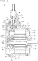
Fig. 2 is a sectional view taken in a line A-A inFig. 1 . -
Fig. 3 is a front view which shows a housing included in the rotating electrical machine inFig. 1 . -
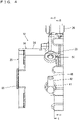
Fig. 4 is a right side view which shows the housing included in the rotating electrical machine inFig. 1 . -
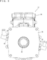
Fig. 5 is a rear view which shows the housing included in the rotating electrical machine inFig. 1 . -
Fig. 6 is a left side view which shows the housing included in the rotating electrical machine inFig. 1 . -
Fig. 7 is a bottom view which shows the housing included in the rotating electrical machine inFig. 1 . -
Fig. 8 is a sectional view taken in a line B-B inFig. 4 . -
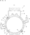
Fig. 9 is an end view taken in a line C-C inFig. 4 . -
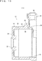
Fig. 10 is a sectional view taken in a line D-D inFig. 5 . -
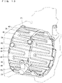
Fig. 11 is an illustrative drawing which shows an example of a cooling water channel of the housing included in the rotating electrical machine inFig. 1 . -
Fig. 12 is an illustrative drawing which shows another example of the cooling water channel of the housing. -
Fig. 13 is an illustrative drawing which shows another example of location for formation of a sand removal hole provided in the housing. -
Fig. 14 is an illustrative drawing which shows still another example of location to form the sand removal hole provided in the housing. - Hereinafter, preferred embodiments of the present invention will be described with reference to the drawings.
- Referring to
Fig. 1 andFig. 2 , a rotatingelectrical machine 10 according to an embodiment of the present invention includes ahousing 12. - Referring to
Fig. 3 through Fig. 10 , thehousing 12 includes acylindrical portion 14 which is generally cylindrical. - The
cylindrical portion 14 has an innercircumferential surface 16 which faces an outer circumferential surface of a stator 58 (which will be described later), anopening 18 at its first axial end region, and a generallyrectangular platy portion 20 provided at its second axial end region. Theplaty portion 20 has a through-hole 22 at its center. At its end region on the side of theopening 18, thecylindrical portion 14 is provided with astorage portion 26 protruding more outward than an outercircumferential surface 24 of thecylindrical portion 14. Thestorage portion 26 has ahollow portion 28 and three through-holes 30 extending outward from thehollow portion 28. - The
cylindrical portion 14 is formed with acooling water channel 32 in its inside (within its thickness). - Referring further to
Fig. 11 , the coolingwater channel 32 includes amain water channel 34 extending in a circumferential direction of thecylindrical portion 14 in a zig-zag fashion so as to surround astator 58; andbypass water channels 36 interconnecting themain water channel 34. - The
main water channel 34 includes a plurality offirst channels 38 and a plurality ofsecond channels 40. The plurality offirst channels 38 each extend axially of thecylindrical portion 14, at a distance from each other in a circumferential direction of thecylindrical portion 14. Thefirst channels 38 which are mutually adjacent in the circumferential direction of thecylindrical portion 14 are laid in an opening pattern somewhat like a letter V, having their respective ends connected with each other by thesecond channel 40 which represents a U turn portion. In other words, in the plurality offirst channels 38, mutually adjacentfirst channels 38 have their first end regions connected with each other and their second end regions connected with each other alternately by thesecond channels 40 which extend in a circumferential direction of thecylindrical portion 14. As a result, themain water channel 34 extending in a zig-zag fashion is obtained. Preferably, themain water channel 34 has a width W1 greater than a thickness T of themain water channel 34. More preferably, the width W1 of themain water channel 34 is not smaller than 1.5 times of the thickness T of the main water channel 34 (seeFig. 6 andFig. 9 ). Also, thesecond channel 40 has a greater width (dimension of thesecond channel 40 in an axial direction of the cylindrical portion 14) than a width (dimension of thefirst channel 38 in a circumferential direction of the cylindrical portion 14) of thefirst channel 38. In other words, the dimension of thesecond channel 40 perpendicular to a direction of water flow is greater than the dimension of thefirst channel 38 perpendicular to a direction of water flow. - The
main water channel 34 as described above is interconnected with each other by thebypass water channels 36. Thebypass water channel 36 is provided at first end portions of themain water channel 34 located at a first axial end region of thecylindrical portion 14, and connect the first end portions of themain water channel 34 with each other. Thebypass water channel 36 is also provided at second end portions of themain water channel 34 located at a second axial end region of thecylindrical portion 14, and connect the second end portions of themain water channel 34 with each other. In other words, thebypass water channel 36 connects portions of themain water channel 34 represented by thesecond channels 40 which are mutually adjacent to each other in the circumferential direction of thecylindrical portion 14, of themain water channel 34. In the present embodiment, thebypass water channels 36 connect the plurality ofsecond channels 40 which are provided at the first axial end region (on the side of the opening 18) of thecylindrical portion 14, i.e., connect all of thesecond channels 40 which are mutually adjacent to each other in the circumferential direction of thecylindrical portion 14, except for a location occupied by a groove portion G (seeFig. 11 ) of a positioning key 60 (which will be described later). Also, thebypass water channels 36 connect the plurality ofsecond channels 40 which are provided at the second axial end region (on the side of the platy portion 20) of thecylindrical portion 14, i.e., connect all of thesecond channels 40 which are mutually adjacent to each other in the circumferential direction of thecylindrical portion 14. Preferably, thebypass water channel 36 has a width W2 smaller than the width W1 of themain water channel 34. More preferably, the width W2 of thebypass water channel 36 is not greater than a half of the width W1 of the main water channel 34 (seeFig. 6 ). In the present embodiment, thebypass water channel 36 has a thickness which is generally equal to the thickness T of themain water channel 34. - On the outer
circumferential surface 24 of thecylindrical portion 14,hollow coupler adapters water channel 32. More specifically, thecoupler adapters opening 18 in the outercircumferential surface 24 of thecylindrical portion 14. Thecoupler adapters cylindrical section 14. Thecoupler adapters couplers coupler 42 is formed as a tube in a shape like a letter L, and has a generally L-shaped through-hole 46. The through-hole 46 communicates with the coolingwater channel 32, and serves as an inlet of water to thecooling water channel 32. Thecoupler 44 is formed as a tube in a shape like a letter V, and has a generally V-shaped through-hole 48. The through-hole 48 communicates with the coolingwater channel 32, and serves as an outlet of water from the coolingwater channel 32. More specifically, the through-holes Fig. 9 andFig. 11 ). - Further, in the outer
circumferential surface 24 of thecylindrical portion 14, sand removal holes 50, 52 are provided to remove core sand from the coolingwater channel 32 after casting of thehousing 12 is complete. More specifically, the sand removal holes 50, 52 are provided at places close to theopening 18 in the outercircumferential surface 24 of thecylindrical portion 14. Thesand removal hole 50 is between thecoupler 42 and thestorage portion 26. Thesand removal hole 52 is on an opposite side from thestorage portion 26 when viewed from thecoupler 44. The sand removal holes 50, 52 communicate with the coolingwater channel 32. More specifically, the sand removal holes 50, 52 communicate with the main water channel 34 (second channels 40) (seeFig. 6 andFig. 7 ,Fig. 9 andFig. 11 ). When thehousing 10 is completed, the sand removal holes 50, 52 are plugged withlids - The
housing 12 described above is manufactured as follows for example. - Inside an unillustrated mold, a core is placed and then molten metal is cast. The mold is for formation of the
housing 12. The core is made into the shape to follow thecooling water channel 32, hollow portions of thecoupler adapters housing 12. Thehousing 12 is then taken out of the mold. The core which is left inside the thickness of thecylindrical portion 14 of thehousing 12 is smashed by applying vibration and is removed out of thecoupler adapters housing 12, thecoupler adapters couplers lids - Returning to
Fig. 1 andFig. 2 , thehousing 12 houses thestator 58. Thestator 58 is disposed at a predetermined position inside thehousing 12, with apositioning key 60. Theopening 18 of thehousing 12 is provided with acover 62. Thecover 62 has a generally rectangular penetratingportion 64 at a position from which access can be made near bolts 98 (which will be described later). Also, thecover 62 is provided with asignal line coupler 66. Thecover 62 is fixed to thehousing 12 with a plurality offasteners 68. - Inside the
housing 12, ashaft 70 is provided. Theshaft 70 penetrates thestator 58. Theshaft 70 has its end portion protruding from the through-hole 22 of thehousing 12. Theshaft 70 is supported rotatably by thecover 62 and thehousing 12, viaball bearings shaft 70, arotor 76 is fixed oppose thestator 58. Between thecover 62 and theshaft 70, there is provided aresolver 78 for detection of a rotating angle of theshaft 70. Theresolver 78 includes aresolver stator 80 which is attached to thecover 62, and aresolver rotor 82 which is attached to theshaft 70. Theresolver stator 80 is disposed at a predetermined position with apositioning key 84. Theresolver rotor 82 is sandwiched from two side thereof, by thecollars 86, 88, and is disposed at a predetermined position. - Three high-
voltage wiring connectors 90 for three-phase electric power are each inserted into corresponding ones of the through-holes 30 of thestorage portion 26. Each of the high-voltage wiring connectors 90 has a lower end terminal 92, which is routed to thehollow portion 28 of the storage portion 26 (seeFig. 8 ). Each high-voltage wiring connector 90 is attached to thestorage portion 26 with afastener 94. - Inside the
hollow portion 28, there is fixed aholder 96 which is made of an insulating material such as a resin. The terminal 92 of the high-voltage wiring connector 90 is held between theholder 96 and abolt 98. Theholder 96 holds, inside thereof, anut 100 and acollar 102. Between the terminal 92 and a head portion of thebolt 98, awasher 104 and aplaty connection member 106 are sandwiched. Thebolt 98 is inserted through theconnection member 106, thewasher 104, the terminal 92 and thecollar 102, and then threaded into thenut 100, thereby fixing these members. The terminal 92 is connected with an unillustrated coil of thestator 58 via thewasher 104 and theconnection member 106. - A
cover 108 is provided at the penetratingportion 64 of thecover 62. Thecover 108 is attached to thecover 62 with a plurality offasteners 110. A gap between thecover 108 and the penetratingportion 64 is sealed with anO ring 112. - According to the
housing 12 of the rotatingelectrical machine 10 as has been described, the coolingwater channel 32 which is provided inside thecylindrical portion 14 not only includes themain water channel 34 that is formed in a zig-zag fashion but also further includes thebypass water channels 36 that interconnect themain water channel 34. When thehousing 12 is cast, a one-piece core which follows the shape of the coolingwater channel 32 is utilized in order to form thecooling water channel 32. By making an arrangement that the coolingwater channel 32 has thebypass water channels 36 which interconnect themain water channel 34, it becomes possible to increase strength of the core. Therefore, it is possible to reduce cases where the core breaks when it is transported or when it is placed in the mold for manufacturing thehousing 12, and increase productivity of thehousing 12. - Of the
main water channel 34 which extends in a zig-zag fashion, end portions located at an axial end region of thecylindrical portion 14 are connected with each other by thebypass water channel 36. This reduces dislocation between the mutually-connected end portions caused by outer forces when the core is transported or when it is placed in the mold, and therefore it is possible to further reduce breaking of the core, and increase productivity of thehousing 12. - Since the
bypass water channels 36 are provided at end portions of themain water channel 34 at both axial end regions of thecylindrical portion 14, it is possible to further improve the strength of the core which is used to form thecooling water channel 32 inside thehousing 12 when thehousing 12 is cast, and it makes possible to further increase productivity of thehousing 12. - The width W1 of the
main water channel 34 is greater than the thickness T of themain water channel 34. Therefore, when compared with a main water channel which has the same cross-sectional area, it is possible to provide a greater amount of cooling to the inner circumferential surface of thehousing 12 than in cases where the width of the main water channel is smaller than the thickness of the main water channel. Therefore, it is possible to increase cooling effect on thestator 58. - The width W2 of the
bypass water channel 36 is smaller than the width W1 of themain water channel 34. Therefore, it is possible to reduce the amount of water which flows in thebypass water channel 36, making it possible to allow an adequate amount of water to flow in themain water channel 34 and to achieve satisfactory cooling effect. - Since it is possible to increase productivity of the
housing 12 as described, it is possible to increase productivity of the rotatingelectrical machine 10. - The
main water channel 34 extends in a zig-zag fashion, in which thefirst channels 38 which are mutually adjacent to each other are laid in an opening pattern somewhat like a letter V. Therefore, it is possible to let the water flow smoothly through the coolingwater channel 32, and to obtain further increased cooling effect. Further, by making the arrangement that thesecond channel 40 has a greater width (dimension of thesecond channel 40 in an axial direction of the cylindrical portion 14) than that of the first channel 38 (dimension of thefirst channel 38 in a circumferential direction of the cylindrical portion 14), it becomes possible to let the water flow more smoothly through the coolingwater channel 32, and therefore obtain further increased cooling effect. - In the embodiment described above, the
bypass water channels 36 connect the plurality of thesecond channels 40, i.e., connect all of thesecond channels 40 which are mutually adjacent to each other in the circumferential direction of thecylindrical portion 14 at the first axial end region (on the side of the opening 18) of thecylindrical portion 14, except for a groove portion G (seeFig. 11 ), and further, connect the plurality of thesecond channels 40, i.e., connect all of thesecond channels 40 which are mutually adjacent to each other in the circumferential direction of thecylindrical portion 14 at the second axial end region (on the side of the platy portion 20) of thecylindrical portion 14. However, the invention is not limited to this. As shown inFig. 12 , in the plurality of thesecond channels 40 provided in the first axial end region of thecylindrical portion 14 and the plurality of thesecond channels 40 provided in the second axial end region of thecylindrical portion 14, formation of thebypass water channel 36 may be skipped every three channels. In other words, there may be an arrangement that after forming thebypass water channel 36 in thecylindrical portion 14 two consecutive times in the circumferential direction, then formation of thebypass water channel 36 is skipped next time. - In the embodiment described above, the sand removal holes 50, 52 are provided only on the first end region side (the side closer to the opening 18) in the outer
circumferential surface 24 of thecylindrical portion 14. However, the invention is not limited to this. In addition to these, a plurality of sand removal holes may be provided on the second end region side (the side closer to the platy portion 20) in the outercircumferential surface 24 of thecylindrical portion 14. - For example, in the case of the embodiment shown in
Fig. 11 , there may be additional sand removal holes provided at positions indicated by alpha-numeric symbols P1, P2 and P3 inFig. 13 . In other words, there may be provided sand removal holes communicating with thesecond channels 40 which are in the second axial end region of thecylindrical portion 14, every othersecond channel 40 in the circumferential direction of thecylindrical portion 14. The sand removal holes are provided in thesecond channels 40 each of which is connected with thebypass water channels 36 at both sides in the circumferential direction of thecylindrical portion 14. In this case, it becomes easier, at the time of manufacturing thehousing 12, to remove the core sand and gases which occur at the time of casting, from the coolingwater channel 32. - Also, in the case of the embodiment shown in
Fig. 12 , there may be additional sand removal holes provided at positions indicated by alpha-numeric symbols P4 and P5 inFig. 14 . In other words, there may be provided sand removal holes communicating with thesecond channels 40 which are in the second axial end region of thecylindrical portion 14, every threesecond channels 40 in the circumferential direction of thecylindrical portion 14. The sand removal holes are provided in thesecond channels 40 each of which is connected with thebypass water channels 36 at both sides in the circumferential direction of thecylindrical portion 14. In this case again, it becomes easier, at the time of manufacturing thehousing 12, to remove the core sand and gases which occur at the time of casting, from the coolingwater channel 32. - In the embodiment described above, the
bypass water channels 36 are provided at both end regions of themain water channel 34. However, the invention s not limited to this. Thebypass water channel 36 may be provided at only one of the first end region and the second end region of themain water channel 34. Also, thebypass water channel 36 may connect any other portions, rather than the end portions, of themain water channel 34. - The main water channel may be formed in a curved fashion, without having any straight portions.
- The present invention being thus far described in terms of preferred embodiments, it is obvious that these may be varied in many ways within the scope and the spirit of the present invention. The scope of the present invention is only limited by the accompanied claims.
-
- 10
- Rotating electrical machine
- 12
- Housing
- 14
- Cylindrical portion
- 16
- Inner circumferential surface of cylindrical portion
- 32
- Cooling water channel
- 34
- Main water channel
- 36
- Bypass water channel
- 50, 52
- Sand removal holes
- 58
- Stator
- 70
- Shaft
- 76
- Rotor
- T
- Thickness of main water channel
- W1
- Width of main water channel
- W2
- Width of bypass water channel
Claims (6)
- A housing for housing a stator of a rotating electrical machine, comprising:a cylindrical portion having an inner circumferential surface for facing an outer circumferential surface of the stator; anda cooling water channel provided inside the cylindrical portion, whereinthe cooling water channel includes a main water channel extending in a circumferential direction of the cylindrical portion in a zig-zag fashion, and a bypass water channel interconnecting the main water channel.
- The housing according to Claim 1, wherein the bypass water channel is provided at end portions of the main water channel located at an axial end region of the cylindrical portion.
- The housing according to Claim 2, wherein the bypass water channel is provided at end portions of the main water channel located at each axial end region of the cylindrical portion.
- The housing according to one of Claims 1 through 3, wherein the main water channel has a greater width than a thickness of the main water channel.
- The housing according to one of Claims 1 through 4, wherein the bypass water channel has a smaller width than the width of the main water channel.
- A rotating electrical machine comprising the housing according to one of Claims 1 through 5.
Applications Claiming Priority (2)
| Application Number | Priority Date | Filing Date | Title |
|---|---|---|---|
| JP2020016643A JP7488661B2 (en) | 2020-02-03 | 2020-02-03 | Housing and rotating electric machine including same |
| PCT/JP2020/048310 WO2021157242A1 (en) | 2020-02-03 | 2020-12-23 | Housing and rotating electrical machine including same |
Publications (2)
| Publication Number | Publication Date |
|---|---|
| EP4102689A1 true EP4102689A1 (en) | 2022-12-14 |
| EP4102689A4 EP4102689A4 (en) | 2023-08-16 |
Family
ID=77199320
Family Applications (1)
| Application Number | Title | Priority Date | Filing Date |
|---|---|---|---|
| EP20917845.8A Withdrawn EP4102689A4 (en) | 2020-02-03 | 2020-12-23 | HOUSING AND ROTATING ELECTRICAL MACHINE WITH IT |
Country Status (5)
| Country | Link |
|---|---|
| US (1) | US20230110424A1 (en) |
| EP (1) | EP4102689A4 (en) |
| JP (1) | JP7488661B2 (en) |
| CN (1) | CN114982102A (en) |
| WO (1) | WO2021157242A1 (en) |
Cited By (4)
| Publication number | Priority date | Publication date | Assignee | Title |
|---|---|---|---|---|
| WO2023248170A1 (en) * | 2022-06-24 | 2023-12-28 | Nemak, S.A.B. De C.V. | Casting mould for producing a cast part formed from a light-metal alloy |
| EP4391323A1 (en) * | 2022-12-19 | 2024-06-26 | Yamaha Hatsudoki Kabushiki Kaisha | Electric motor |
| EP4542828A1 (en) * | 2023-10-18 | 2025-04-23 | Weg Equipamentos Elétricos S/A | Single-piece casing for rotating electric machines and corresponding rotating electric machine |
| EP4583376A1 (en) * | 2024-01-04 | 2025-07-09 | Toyota Jidosha Kabushiki Kaisha | Motor unit |
Families Citing this family (3)
| Publication number | Priority date | Publication date | Assignee | Title |
|---|---|---|---|---|
| US12348108B2 (en) * | 2020-07-22 | 2025-07-01 | Toshiba Industrial Products And Systems Corporation | Rotating electric machine cooling frame and method of manufacturing rotating electric machine cooling frame |
| TW202304735A (en) | 2021-07-30 | 2023-02-01 | 日商島野股份有限公司 | Operating device for human-powered vehicle and human-powered vehicle |
| JP7468591B1 (en) * | 2022-09-29 | 2024-04-16 | 株式会社明電舎 | Cooling structure for rotating electric machine and rotating electric machine |
Family Cites Families (17)
| Publication number | Priority date | Publication date | Assignee | Title |
|---|---|---|---|---|
| ATE153192T1 (en) * | 1992-09-03 | 1997-05-15 | Fhp Motors Gmbh | SURFACE COOLED, CLOSED ELECTRICAL MACHINE |
| JP3300200B2 (en) * | 1995-06-20 | 2002-07-08 | 株式会社日立製作所 | Rotating electric machines and electric vehicles |
| JP2004312886A (en) * | 2003-04-08 | 2004-11-04 | Suzuki Motor Corp | Motor cooling structure |
| DE102009001387A1 (en) * | 2009-03-06 | 2010-09-09 | Robert Bosch Gmbh | electric machine |
| JP5333468B2 (en) | 2011-01-27 | 2013-11-06 | 株式会社安川電機 | Rotating electric machine |
| JP5274613B2 (en) * | 2011-04-21 | 2013-08-28 | 三菱電機株式会社 | Outer-cooled rotary electric machine and casing used therefor |
| WO2013069322A1 (en) * | 2011-11-11 | 2013-05-16 | 株式会社安川電機 | Rotating electrical machine and vehicle |
| JP5547783B2 (en) * | 2012-09-27 | 2014-07-16 | 株式会社小松製作所 | Electric motor and its cooling water circuit |
| KR102040526B1 (en) * | 2012-11-08 | 2019-11-05 | 엘지이노텍 주식회사 | Motor |
| US20140246933A1 (en) * | 2013-03-04 | 2014-09-04 | Remy Technologies, Llc | Liquid-cooled rotary electric machine having heat source-surrounding fluid passage |
| US20150308456A1 (en) * | 2014-02-19 | 2015-10-29 | Honeywell International Inc. | Electric motor-driven compressor having bi-directional liquid coolant passage |
| JP6315361B2 (en) * | 2014-04-04 | 2018-04-25 | ダイナミック イー フロー ゲーエムベーハー | Electronic hollow conductor for electromagnetic machinery |
| JP6302736B2 (en) * | 2014-04-28 | 2018-03-28 | 日立オートモティブシステムズ株式会社 | Rotating electric machine |
| JP6470676B2 (en) * | 2015-12-24 | 2019-02-13 | 株式会社クボタ | Liquid cooling motor |
| JP6643130B2 (en) | 2016-02-12 | 2020-02-12 | 東芝産業機器システム株式会社 | Electric motor manufacturing method |
| US10097066B2 (en) * | 2016-03-17 | 2018-10-09 | Ford Global Technologies, Llc | Electric machine for vehicle |
| DE102016225521A1 (en) * | 2016-12-20 | 2018-06-21 | Bayerische Motoren Werke Aktiengesellschaft | Cooling jacket housing, in particular for an electrical machine |
-
2020
- 2020-02-03 JP JP2020016643A patent/JP7488661B2/en active Active
- 2020-12-23 EP EP20917845.8A patent/EP4102689A4/en not_active Withdrawn
- 2020-12-23 US US17/795,897 patent/US20230110424A1/en not_active Abandoned
- 2020-12-23 CN CN202080094551.2A patent/CN114982102A/en not_active Withdrawn
- 2020-12-23 WO PCT/JP2020/048310 patent/WO2021157242A1/en not_active Ceased
Cited By (5)
| Publication number | Priority date | Publication date | Assignee | Title |
|---|---|---|---|---|
| WO2023248170A1 (en) * | 2022-06-24 | 2023-12-28 | Nemak, S.A.B. De C.V. | Casting mould for producing a cast part formed from a light-metal alloy |
| LU502349B1 (en) * | 2022-06-24 | 2024-01-09 | Nemak Sab De Cv | Casting mold for producing a casting made from a light metal alloy |
| EP4391323A1 (en) * | 2022-12-19 | 2024-06-26 | Yamaha Hatsudoki Kabushiki Kaisha | Electric motor |
| EP4542828A1 (en) * | 2023-10-18 | 2025-04-23 | Weg Equipamentos Elétricos S/A | Single-piece casing for rotating electric machines and corresponding rotating electric machine |
| EP4583376A1 (en) * | 2024-01-04 | 2025-07-09 | Toyota Jidosha Kabushiki Kaisha | Motor unit |
Also Published As
| Publication number | Publication date |
|---|---|
| JP7488661B2 (en) | 2024-05-22 |
| EP4102689A4 (en) | 2023-08-16 |
| WO2021157242A1 (en) | 2021-08-12 |
| CN114982102A (en) | 2022-08-30 |
| US20230110424A1 (en) | 2023-04-13 |
| JP2021125929A (en) | 2021-08-30 |
Similar Documents
| Publication | Publication Date | Title |
|---|---|---|
| US20230110424A1 (en) | Housing and rotating electrical machine including the same | |
| US8183723B2 (en) | Cooling jacket and stator assembly for rotary electric device | |
| EP0868012B1 (en) | Fully enclosed linear motor armature | |
| US8973363B2 (en) | Electrical machine comprising cooling channels | |
| US7737585B2 (en) | Electric machine with improved water cooling system | |
| US7626292B2 (en) | Cast groove electric motor/generator cooling mechanism | |
| US5751077A (en) | Fluid-cooled linear motor armature | |
| EP3993236A1 (en) | Liquid-cooled motor | |
| US12176773B2 (en) | Rotary electric machine with improved stator cooling | |
| EP0858692B1 (en) | Liquid cooling system for electrical machines | |
| KR101767621B1 (en) | Motor Housing and Manufacturing Method of it | |
| CA2215765C (en) | Rotors and methods of manufacturing such rotors | |
| CN112020814A (en) | Electric motor and method for producing same | |
| CN101682232B (en) | Ac generator for vehicle | |
| US3686522A (en) | Rotor with a liquid-cooled winding for an electrical machine | |
| JP2023016010A (en) | electromechanical | |
| US20070210667A1 (en) | Squirrel-cage rotor | |
| US12549043B2 (en) | Rotating electric machine | |
| JPS63108964A (en) | Production of composite steel ingot shaft | |
| CN120185243A (en) | motor | |
| WO2012066072A2 (en) | Rotary piston internal combustion engine | |
| EP4391323A1 (en) | Electric motor | |
| CN117277650A (en) | Motor | |
| CN117997025A (en) | Cooling structure and manufacturing method of shell comprising same | |
| JP2006340585A (en) | Electric motor for vehicles |
Legal Events
| Date | Code | Title | Description |
|---|---|---|---|
| STAA | Information on the status of an ep patent application or granted ep patent |
Free format text: STATUS: THE INTERNATIONAL PUBLICATION HAS BEEN MADE |
|
| PUAI | Public reference made under article 153(3) epc to a published international application that has entered the european phase |
Free format text: ORIGINAL CODE: 0009012 |
|
| STAA | Information on the status of an ep patent application or granted ep patent |
Free format text: STATUS: REQUEST FOR EXAMINATION WAS MADE |
|
| 17P | Request for examination filed |
Effective date: 20220902 |
|
| AK | Designated contracting states |
Kind code of ref document: A1 Designated state(s): AL AT BE BG CH CY CZ DE DK EE ES FI FR GB GR HR HU IE IS IT LI LT LU LV MC MK MT NL NO PL PT RO RS SE SI SK SM TR |
|
| DAV | Request for validation of the european patent (deleted) | ||
| DAX | Request for extension of the european patent (deleted) | ||
| A4 | Supplementary search report drawn up and despatched |
Effective date: 20230718 |
|
| RIC1 | Information provided on ipc code assigned before grant |
Ipc: H02K 5/22 20060101ALN20230712BHEP Ipc: H02K 9/19 20060101ALI20230712BHEP Ipc: H02K 5/06 20060101ALI20230712BHEP Ipc: H02K 5/20 20060101AFI20230712BHEP |
|
| P01 | Opt-out of the competence of the unified patent court (upc) registered |
Effective date: 20230713 |
|
| STAA | Information on the status of an ep patent application or granted ep patent |
Free format text: STATUS: EXAMINATION IS IN PROGRESS |
|
| 17Q | First examination report despatched |
Effective date: 20250103 |
|
| STAA | Information on the status of an ep patent application or granted ep patent |
Free format text: STATUS: THE APPLICATION IS DEEMED TO BE WITHDRAWN |
|
| 18D | Application deemed to be withdrawn |
Effective date: 20250507 |