EP4102688A1 - Electric machine and motor - Google Patents
Electric machine and motor Download PDFInfo
- Publication number
- EP4102688A1 EP4102688A1 EP21771842.8A EP21771842A EP4102688A1 EP 4102688 A1 EP4102688 A1 EP 4102688A1 EP 21771842 A EP21771842 A EP 21771842A EP 4102688 A1 EP4102688 A1 EP 4102688A1
- Authority
- EP
- European Patent Office
- Prior art keywords
- housing
- inverter
- joint surface
- motor
- ring
- Prior art date
- Legal status (The legal status is an assumption and is not a legal conclusion. Google has not performed a legal analysis and makes no representation as to the accuracy of the status listed.)
- Granted
Links
Images






Classifications
-
- H—ELECTRICITY
- H02—GENERATION; CONVERSION OR DISTRIBUTION OF ELECTRIC POWER
- H02K—DYNAMO-ELECTRIC MACHINES
- H02K5/00—Casings; Enclosures; Supports
- H02K5/04—Casings or enclosures characterised by the shape, form or construction thereof
- H02K5/20—Casings or enclosures characterised by the shape, form or construction thereof with channels or ducts for flow of cooling medium
- H02K5/203—Casings or enclosures characterised by the shape, form or construction thereof with channels or ducts for flow of cooling medium specially adapted for liquids, e.g. cooling jackets
-
- F—MECHANICAL ENGINEERING; LIGHTING; HEATING; WEAPONS; BLASTING
- F16—ENGINEERING ELEMENTS AND UNITS; GENERAL MEASURES FOR PRODUCING AND MAINTAINING EFFECTIVE FUNCTIONING OF MACHINES OR INSTALLATIONS; THERMAL INSULATION IN GENERAL
- F16J—PISTONS; CYLINDERS; SEALINGS
- F16J15/00—Sealings
- F16J15/02—Sealings between relatively-stationary surfaces
- F16J15/14—Sealings between relatively-stationary surfaces by means of granular or plastic material, or fluid
-
- H—ELECTRICITY
- H02—GENERATION; CONVERSION OR DISTRIBUTION OF ELECTRIC POWER
- H02K—DYNAMO-ELECTRIC MACHINES
- H02K11/00—Structural association of dynamo-electric machines with electric components or with devices for shielding, monitoring or protection
- H02K11/30—Structural association with control circuits or drive circuits
- H02K11/33—Drive circuits, e.g. power electronics
-
- H—ELECTRICITY
- H02—GENERATION; CONVERSION OR DISTRIBUTION OF ELECTRIC POWER
- H02K—DYNAMO-ELECTRIC MACHINES
- H02K5/00—Casings; Enclosures; Supports
- H02K5/04—Casings or enclosures characterised by the shape, form or construction thereof
- H02K5/10—Casings or enclosures characterised by the shape, form or construction thereof with arrangements for protection from ingress, e.g. water or fingers
-
- H—ELECTRICITY
- H02—GENERATION; CONVERSION OR DISTRIBUTION OF ELECTRIC POWER
- H02K—DYNAMO-ELECTRIC MACHINES
- H02K9/00—Arrangements for cooling or ventilating
- H02K9/19—Arrangements for cooling or ventilating for machines with closed casing and closed-circuit cooling using a liquid cooling medium, e.g. oil
-
- H—ELECTRICITY
- H02—GENERATION; CONVERSION OR DISTRIBUTION OF ELECTRIC POWER
- H02P—CONTROL OR REGULATION OF ELECTRIC MOTORS, ELECTRIC GENERATORS OR DYNAMO-ELECTRIC CONVERTERS; CONTROLLING TRANSFORMERS, REACTORS OR CHOKE COILS
- H02P27/00—Arrangements or methods for the control of AC motors characterised by the kind of supply voltage
- H02P27/04—Arrangements or methods for the control of AC motors characterised by the kind of supply voltage using variable-frequency supply voltage, e.g. inverter or converter supply voltage
- H02P27/06—Arrangements or methods for the control of AC motors characterised by the kind of supply voltage using variable-frequency supply voltage, e.g. inverter or converter supply voltage using DC to AC converters or inverters
-
- Y—GENERAL TAGGING OF NEW TECHNOLOGICAL DEVELOPMENTS; GENERAL TAGGING OF CROSS-SECTIONAL TECHNOLOGIES SPANNING OVER SEVERAL SECTIONS OF THE IPC; TECHNICAL SUBJECTS COVERED BY FORMER USPC CROSS-REFERENCE ART COLLECTIONS [XRACs] AND DIGESTS
- Y02—TECHNOLOGIES OR APPLICATIONS FOR MITIGATION OR ADAPTATION AGAINST CLIMATE CHANGE
- Y02T—CLIMATE CHANGE MITIGATION TECHNOLOGIES RELATED TO TRANSPORTATION
- Y02T10/00—Road transport of goods or passengers
- Y02T10/60—Other road transportation technologies with climate change mitigation effect
- Y02T10/64—Electric machine technologies in electromobility
Definitions
- the present invention relates to an electric device such as a motor, and a motor.
- the present inventors have prototyped a prototype provided with an O-ring made of an elastic material and a sealing material made of a liquid gasket.
- the O-ring of the prototype surrounds the communication port of each cooling water passage while being interposed between the motor case and the inverter case in the communicating portion between the motor cooling water passage and the inverter cooling water passage.
- the sealing material is interposed between the joint surface of the motor case and the joint surface of the inverter case to seal the inside of the motor case and the inside of the inverter case.
- the present invention has been made in view of the above background, and an object of the present invention is to provide an electric device and a motor as follows. That is, the present invention provides an electric device and a motor capable of suppressing refrigerant leakage from a joint portion by an O-ring, suppressing deterioration of the O-ring due to adhesion of a liquid gasket, and enhancing airtightness of a housing and a cover joined to each other or airtightness of two housings joined to each other at low cost.
- Fig. 1 is a perspective view illustrating a motor 1 according to an embodiment.
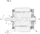
- Fig. 2 is a longitudinal cross-sectional view illustrating a shaft 6, a rotor 7, and a stator 5 of the motor 1.
- the motor 1 includes a motor unit 2 and an inverter unit 50.
- the central portion of the shaft 6 in the rotation axis direction, the rotor 7, and the stator 5 are housed in a cylindrical hollow of the motor housing 3 as a first housing.
- One side (arrow A direction side) and the other side (arrow B direction side) of the shaft 6 in the rotation axis direction are rotatably supported by ball bearings 8.
- Each of the two ball bearings 8 is fixed in the motor housing 3.
- the rotor 7 rotates integrally with the shaft 6.
- the rotor 7 and the central portion of the shaft 6 in the rotation axis direction are disposed in the hollow of the stator 5.
- the inverter unit 50 supplies power of a three-phase power supply to the motor unit 2 at a frequency based on a command in accordance with a command sent from a host device such as an engine control unit (ECU) of a vehicle.
- the inverter unit 50 including the inverter cover 51, the inverter circuit, and the inverter housing 55 is disposed on the other side (arrow B direction side) of the motor unit 2 in the rotation axis direction.
- Each of the motor housing 3, the inverter housing 55, and the inverter cover 51 is made of a cast product having a hollow structure.
- a control substrate and the like are disposed in the hollow of the inverter housing 55.
- an insulated gate bipolar transistor (IGBT) module or the like constituting a part of the inverter circuit is disposed.
- a liquid supply pipe 9 is connected to the outer peripheral surface of the motor housing 3. Liquid refrigerant such as cooling water sent from a cooling device is supplied into the liquid supply pipe 9.
- the spread portion of the liquid gasket 41 flows into the groove 3d before reaching the O-ring 39 and is prevented from further spreading.
- the groove 3d suppresses the adhesion of the liquid gasket 41 to the O-ring 39, the deterioration of the O-ring 39 due to the adhesion of the liquid gasket 41 can be suppressed.
- a groove may be provided only in the former of the joint surface 3b of the motor housing 3 and the joint surface 55a of the inverter housing 55
- a groove may be provided only in the latter, or a groove may be provided in each of the former and the latter.
- the communication ports (3a1 and 55b1) and the groove 3d are arranged outside the frame of the sealing material 40 having a frame shape
- the communication ports (3a1 and 55b1) and the groove 3d may be arranged inside the frame.
- Fig. 8 is a partial perspective view illustrating the refrigerant flow path 55b and the periphery thereof in the inverter housing 55.
- the inverter housing 55 includes a second joint surface 55c joined to the inverter cover (51 in Fig. 1 ) on the other side (arrow B direction side) in the rotation axis direction.
- the end on the other side in the rotation axis direction of the refrigerant flow path 55b of the inverter housing 55 opens toward the other side as a second communication port 55b2 on the second joint surface 55c.
- the second joint surface 55c is provided with a second annular groove surrounding the second communication port 55b2, and a second O-ring 56 is set in the second annular groove.
- Fig. 9 is a perspective view illustrating the inverter cover 51 from one side (arrow A direction side) in the rotation axis direction.
- the inverter cover 51 includes a joint surface 51a joined to the second joint surface (55c in Fig. 8 ) of the inverter housing and a refrigerant flow path 51b.
- One end of the refrigerant flow path 51b opens toward one side (arrow A direction side) in the rotation axis direction as a communication port 51b1 on the joint surface 51a.
- the second O-ring 56 illustrated in Fig. 8 is interposed between the inverter housing 55 and the inverter cover (51 in Fig. 9 ) and is disposed so as to surround the respective communication ports (55b2 and 51b) of the refrigerant flow paths (55b and 51b) communicating with each other.
- the second O-ring 56 can suppress the refrigerant leakage from the joint portion between the inverter housing 55 and the inverter cover 51 to the inside and outside of the inverter housing 55 and the inverter cover 51.
- the second groove 55e is disposed between the second sealing material 42 and the second O-ring 56 in the surface direction. Even when the liquid gasket which is the precursor of the second sealing material 42 spreads in the surface direction at the time of application, the spread portion of the liquid gasket flows into the second groove 55e before reaching the second O-ring 56 and is prevented from further spreading. As described above, since the second groove 55e suppresses the adhesion of the liquid gasket to the second O-ring 56, deterioration of the second O-ring 56 due to the adhesion of the liquid gasket can be suppressed.
- the refrigerant flow path 51b of the inverter cover 51 is provided inside the cover bottom wall and extends in a direction orthogonal to the rotation axis direction.
- the refrigerant flowing into the refrigerant flow path 3a of the motor housing 3 through the liquid supply pipe 9 illustrated in Fig. 4 flows in the refrigerant flow path 3a to cool the motor housing 3, and then flows into the refrigerant flow path 55b of the inverter housing 55 illustrated in Fig. 7 . Thereafter, the refrigerant flows in the refrigerant flow path 55b to cool the inverter housing 55, and then flows into the refrigerant flow path 51b of the inverter cover 51 illustrated in Fig. 9 . Then, the refrigerant flows in the refrigerant flow path 51b to cool the inverter cover 51 and the IGBT module (52 in Fig. 10 ), and then is discharged to the outside through a waste liquid pipe (not illustrated). The discharged refrigerant is sent to the cooling device through the external pipe to be cooled, and then sent again to the liquid supply pipe 9 of the motor unit 2.
- Fig. 10 is a block diagram illustrating a circuit configuration of the inverter unit 50.
- the inverter unit 50 includes a power supply circuit 53, an inverter control circuit 54, and an inverter circuit 57.
- An ignition power supply of the vehicle is supplied to the power supply circuit 53 and the inverter circuit 57.
- the power supply circuit converts the voltage of the ignition power supply into a stable 5 V power supply, and supplies the 5 V power supply to the inverter control circuit 54.
- the inverter control circuit 54 controls the inverter circuit 57 in accordance with a control signal transmitted from the host device.
- the inverter circuit 57 includes the IGBT module 52 described above.
- the power supply circuit 53, the inverter control circuit 54, and the inverter circuit 57 except for the IGBT module 52 are housed in the inverter housing (55 in Fig. 1 ). As described above, the IGBT module 52 is housed in the inverter case (51 in Fig. 1 ).
- a first aspect is an electric device including a housing (for example, the inverter housing 55) and a cover (for example, the inverter cover 51) that covers an opening of the housing, or a first housing (for example, the motor housing 3) and a second housing (for example, the inverter housing 55), each of the housing and the cover, or each of the first housing and the second housing including a joint surface (for example, the joint surface 3b and the joint surface 55a, or the second joint surface 55c and the joint surface 51a) to be joined to each other, and a liquid path (for example, the refrigerant flow paths 3a, 55b, and 51b) serving as a refrigerant flow path, each liquid path being opened as a communication port at the joint surface and communicating with each other; and a sealing material (for example, the sealing material 40 and the second sealing material 42) interposed between each joint surface, and an O-ring (for example, the O-ring 39 and the second O-ring 56), wherein the O-ring is interposed between the housing and
- the groove disposed on the joint surface of at least one of the housing and the cover or the joint surface of at least one of the first housing and the second housing suppresses adhesion of the liquid gasket to the O-ring, so that deterioration of the O-ring due to adhesion of the liquid gasket can be suppressed.
- the sealing material which is a dry body of the liquid gasket interposed between the joint surfaces of the housing and the cover or the joint surfaces of the first housing and the second housing, can enhance the airtightness of the housing and the cover or the first housing and the second housing at low cost.
- a third aspect is a motor as the electric device according to the configuration of the first aspect, wherein the first housing includes a motor housing that houses a shaft, a rotor, and a stator, and the second housing includes an inverter housing that houses a control substrate.
- a fourth aspect is a motor according to the configuration of the third aspect, the motor including: an inverter cover that closes an opening of the inverter housing, each of the inverter housing and the inverter cover including a joint surface joined to each other and a liquid path serving as a refrigerant flow path, each liquid path of the inverter housing and the inverter cover being opened as a communication port at the joint surface and communicating with each other, wherein a second sealing material (for example, the second sealing material 42) and a second O-ring (for example, the second O-ring 56) interposed between the joint surface of the inverter housing and the joint surface of the inverter cover are disposed, the O-ring is disposed to surround each of the communication port of the inverter housing and the communication port of the inverter cover that communicate with each other, and at least one of the inverter housing and the inverter cover includes a second groove disposed between the second sealing material and the second O-ring on the joint surface in a surface direction of the joint surface.
- the fourth aspect for each of the joint portion between the motor housing and the inverter housing and the joint portion between the inverter housing and the inverter cover, refrigerant leakage from the joint portion can be suppressed by the O-ring and the second O-ring. Furthermore, according to the fourth aspect, the deterioration of the O-ring and the second O-ring due to the adhesion of the liquid gasket can be suppressed for each of the two connection portions, and the airtightness of the motor housing, the inverter housing, and the inverter cover can be suppressed at low cost.
Landscapes
- Engineering & Computer Science (AREA)
- Power Engineering (AREA)
- General Engineering & Computer Science (AREA)
- Microelectronics & Electronic Packaging (AREA)
- Mechanical Engineering (AREA)
- Motor Or Generator Frames (AREA)
- Inverter Devices (AREA)
Abstract
Description
- The present invention relates to an electric device such as a motor, and a motor.
- Conventionally, there is known an electric device including a first housing and a second housing, and each of the first housing and the second housing includes a joint surface joined to each other and a liquid path serving as a refrigerant flow path.
- For example, a motor as an electric device described in
Patent Literature 1 includes a motor unit and an inverter unit. The motor unit includes a motor case as a first housing, and a rotating shaft, a rotor, and a stator housed in the motor case. The inverter unit includes an inverter case as a second housing, and a capacitor and an inverter circuit housed in the inverter case. The motor case and the inverter case are joined to each other in the rotation axis direction of the rotor. - The motor case includes a motor cooling water passage as a liquid path extending in the rotation axis direction of the rotor. One end of the motor cooling water passage in the rotation axis direction is opened as a drain port, and the other end is opened as a communication port at a joint surface with the inverter case. In addition, the inverter case includes an inverter cooling water passage extending in a direction orthogonal to the rotation axis direction of the rotor and then bent and extending toward the motor case. One end of the inverter cooling water passage is opened as a communication port at a joint surface with the motor case, and the other end is opened as a water supply port. The motor cooling water passage and the inverter cooling water passage communicate with each other through communication ports. The cooling water flowing into the inverter cooling water passage from the water supply port of the inverter case flows through the inverter cooling water passage and then flows into the motor cooling water passage of the motor case. Thereafter, the cooling water flows in the motor cooling water passage and is then discharged to the outside through the drain port.
- According to
Patent Literature 1, in the motor having such a configuration, both the motor unit and the inverter unit can be cooled by the same cooling water circuit. - Patent Literature 1:
JP 2006-197781 A - However, in this motor, in the communicating portion between the motor cooling water passage and the inverter cooling water passage, there is a possibility that the cooling water in the passage leaks out to the inside or the outside of the case from a minute gap formed between the joint surfaces of the two cases. In addition, in this motor, airtightness in the motor case and the inverter case cannot be sufficiently secured.
- Therefore, the present inventors have prototyped a prototype provided with an O-ring made of an elastic material and a sealing material made of a liquid gasket. The O-ring of the prototype surrounds the communication port of each cooling water passage while being interposed between the motor case and the inverter case in the communicating portion between the motor cooling water passage and the inverter cooling water passage. The sealing material is interposed between the joint surface of the motor case and the joint surface of the inverter case to seal the inside of the motor case and the inside of the inverter case. According to the prototype having such a configuration, the O-ring surrounding each of the communication port of the motor cooling water passage and the communication port of the inverter cooling water passage seals the minute gap between the joint surfaces of both the cases, whereby the leakage of the cooling water from the gap to the inside and outside of the case can be suppressed. In addition, the sealing member interposed between the joint surfaces of both the cases seals the inside of the motor case and the inside of the inverter case, so that airtightness in the motor case and the inverter case can be enhanced.
- However, in this prototype, it has been found that, at the time of joining the motor case and the inverter case, there is a possibility that the sealing material made of the liquid gasket spreads along the joint surface and adheres to the O-ring, and a new problem that deterioration of the O-ring is accelerated by the adhesion may occur. If a solid gasket such as a metal gasket is used instead of the liquid gasket, it is possible to avoid deterioration of the O-ring due to adhesion of the liquid gasket. However, since the solid gasket is more expensive than the liquid gasket, cost reduction cannot be achieved.
- Although the problem caused in the configuration including the two housings that communicate the two cooling water passages at the respective joint surfaces has been described, the same problem may occur in the configuration including the housing and the cover that communicate the two liquid paths at the respective joint surfaces. For example, there is known a motor that includes an inverter housing and an inverter cover that closes an opening of the inverter housing, and communicates a liquid path of the inverter housing and a liquid path of the inverter cover at respective joint surfaces of the inverter housing and the inverter cover. Such a motor may also have a similar problem.
- The present invention has been made in view of the above background, and an object of the present invention is to provide an electric device and a motor as follows. That is, the present invention provides an electric device and a motor capable of suppressing refrigerant leakage from a joint portion by an O-ring, suppressing deterioration of the O-ring due to adhesion of a liquid gasket, and enhancing airtightness of a housing and a cover joined to each other or airtightness of two housings joined to each other at low cost.
- One aspect of the present invention is an electric device including: a housing and a cover that covers an opening of the housing, or a first housing and a second housing, each of the housing and the cover, or each of the first housing and the second housing including a joint surface to be joined to each other, and a liquid path serving as a refrigerant flow path, each liquid path being opened as a communication port at the joint surface and communicating with each other; and a sealing material interposed between each joint surface, and an O-ring, wherein the O-ring is interposed between the housing and the cover or between the first housing and the second housing, and is disposed to surround each communication port of each liquid path communicating with each other, and at least one of the housing and the cover or at least one of the first housing and the second housing includes a groove disposed between the sealing material and the O-ring on the joint surface in a surface direction of the joint surface.
- According to the present invention, there is an excellent effect that degradation of the O-ring due to adhesion of the liquid gasket can be suppressed while refrigerant leakage from the joint portion is suppressed by the O-ring, and airtightness of the housing and the cover joined to each other or the two housings joined to each other can be enhanced at low cost.
-
-
Fig. 1 is a perspective view illustrating a motor according to an embodiment. -
Fig. 2 is a longitudinal cross-sectional view illustrating a shaft, a rotor, and a stator of the motor. -
Fig. 3 is a transverse cross-sectional view illustrating the stator and the rotor of the motor. -
Fig. 4 is a perspective view illustrating a motor housing of the motor from the other side in a rotation axis direction. -
Fig. 5 is a plan view illustrating a joint surface of the motor housing. -
Fig. 6 is an enlarged partial perspective view illustrating a communication port and a periphery thereof in the motor housing. -
Fig. 7 is a perspective view illustrating an inverter housing of the motor from one side in a rotation axis direction. -
Fig. 8 is a partial perspective view illustrating a refrigerant flow path and a periphery thereof in the inverter housing. -
Fig. 9 is a perspective view illustrating an inverter cover of the motor from one side in a rotation axis direction. -
Fig. 10 is a block diagram illustrating a circuit configuration of an inverter unit of the motor. - Hereinafter, an embodiment of a motor to which the present invention is applied will be described with reference to the drawings.
-
Fig. 1 is a perspective view illustrating amotor 1 according to an embodiment.Fig. 2 is a longitudinal cross-sectional view illustrating ashaft 6, arotor 7, and astator 5 of themotor 1. Themotor 1 includes amotor unit 2 and aninverter unit 50. - The
motor unit 2 includes an interior permanent magnet (IPM) motor, and includes amotor housing 3 illustrated inFig. 1 , and theshaft 6, therotor 7, and thestator 5 illustrated inFig. 2 . Theshaft 6 as a rotating shaft member is supported so as to be rotatable about a rotation axis L indicated by an alternate long and short dash line in the drawing. The extending direction of the rotation axis L is an example of a rotation axis direction in the present invention. The arrow A direction inFig. 1 is an example of one side in the rotation axis direction in the present invention. The arrow B direction inFig. 1 is an example of the other side in the rotation axis direction in the present invention. - The central portion of the
shaft 6 in the rotation axis direction, therotor 7, and thestator 5 are housed in a cylindrical hollow of themotor housing 3 as a first housing. One side (arrow A direction side) and the other side (arrow B direction side) of theshaft 6 in the rotation axis direction are rotatably supported byball bearings 8. Each of the twoball bearings 8 is fixed in themotor housing 3. - The
rotor 7 rotates integrally with theshaft 6. Therotor 7 and the central portion of theshaft 6 in the rotation axis direction are disposed in the hollow of thestator 5. -
Fig. 3 is a transverse cross-sectional view illustrating thestator 5 and therotor 7 of themotor 1. Thestator 5 includes acylindrical stator core 5a and aflat wire coil 5b which is a winding wound around thestator core 5a. Therotor 7 is disposed in the hollow of thestator core 5a. In addition, therotor 7 includes arotor core 7a and a plurality ofpermanent magnets 7b embedded in therotor core 7a so as to be arranged in the circumferential direction around the rotation axis L of therotor 7. InFig. 3 , hatching to be applied to the cross section of theflat wire coil 5b is omitted. - Hereinafter, the circumferential direction around the rotation axis L is simply referred to as the circumferential direction. The radial direction around the rotation axis L is simply referred to as the radial direction.
- As illustrated in
Fig. 1 , themotor unit 2 and theinverter unit 50 are adjacent to each other in the rotation axis direction, and themotor housing 3 and theinverter housing 55 are joined to each other in the rotation axis direction. An end on the other side (arrow B direction side) in the rotation axis direction of theinverter housing 55 which is the housing in the present invention and is also the second housing is largely opened toward the other side. This opening is closed by aninverter cover 51 as a cover. - The
inverter unit 50 supplies power of a three-phase power supply to themotor unit 2 at a frequency based on a command in accordance with a command sent from a host device such as an engine control unit (ECU) of a vehicle. Theinverter unit 50 including theinverter cover 51, the inverter circuit, and theinverter housing 55 is disposed on the other side (arrow B direction side) of themotor unit 2 in the rotation axis direction. - Each of the
motor housing 3, theinverter housing 55, and theinverter cover 51 is made of a cast product having a hollow structure. A control substrate and the like are disposed in the hollow of theinverter housing 55. In theinverter cover 51, an insulated gate bipolar transistor (IGBT) module or the like constituting a part of the inverter circuit is disposed. - A
liquid supply pipe 9 is connected to the outer peripheral surface of themotor housing 3. Liquid refrigerant such as cooling water sent from a cooling device is supplied into theliquid supply pipe 9. -
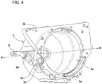
Fig. 4 is a perspective view illustrating themotor housing 3 from the other side (arrow B direction side) in the rotation axis direction. Themotor housing 3 includes a hollow 3c that houses the stator (5 inFig. 2 ) and the rotor (7 inFig. 2 ), arefrigerant flow path 3a as a liquid path, and ajoint surface 3b joined to the inverter housing (55 inFig. 1 ). Therefrigerant flow path 3a communicates with theliquid supply pipe 9, extends in the circumferential direction, and then extends from one side (arrow A direction side) toward the other side in the rotation axis direction. The other end of therefrigerant flow path 3a in the rotational axis direction opens toward the other side as a communication port 3a1 on thejoint surface 3b. -
Fig. 5 is a plan view illustrating thejoint surface 3b of themotor housing 3. On thejoint surface 3b, a sealingmaterial 40 made of a dry body of a liquid gasket is disposed so as to surround the hollow 3c with a predetermined width. The sealingmaterial 40 is interposed between thejoint surface 3b of themotor housing 3 and a joint surface of the inverter housing described later to seal the hollow 3c of themotor housing 3 and the hollow of the inverter housing, so that airtightness of both housings can be enhanced at low cost. InFig. 5 , the sealingmaterial 40 is hatched for convenience, but the hatching does not indicate the cross section of the sealingmaterial 40. The same applies to a liquid gasket (41) illustrated inFig. 6 described later. The sealingmaterial 40 is provided to prevent dust and water droplets from entering themotor housing 3 and theinverter housing 55 from the outside. -
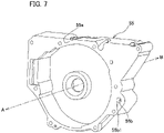
Fig. 6 is an enlarged partial perspective view illustrating the communication port 3a1 and the periphery thereof in themotor housing 3.Fig. 7 is a perspective view illustrating theinverter housing 55 from one side (arrow A direction side) in the rotation axis direction. InFig. 7 , for convenience, illustration of the sealing material (40) is omitted. As illustrated inFig. 6 , themotor housing 3 includes anannular groove 3e surrounding the communication port 3a1 of therefrigerant flow path 3a on thejoint surface 3b. An O-ring 39 made of an elastic body such as heat-resistant rubber is set in theannular groove 3e. - As illustrated in
Fig. 7 , theinverter housing 55 includes ajoint surface 55a joined to the joint surface (3b inFig. 6 ) of the motor housing, and arefrigerant flow path 55b as a liquid path. An end of therefrigerant flow path 55b on one side (arrow A direction side) in the rotation axis direction opens toward the one side as a communication port 55b1. Themotor housing 3 illustrated inFig. 6 and theinverter housing 55 illustrated inFig. 7 are fixed to each other by a bolt and a nut in a state where the joint surfaces (3b and 55a) are joined to each other. Then, therefrigerant flow path 3a of themotor housing 3 and therefrigerant flow path 55b of the inverter housing communicate with each other through the communication ports (3a1 and 55b1). The O-ring 39 is interposed between themotor housing 3 and theinverter housing 55 and surrounds the respective communication ports (3a1 and 3b1) of the two refrigerant flow paths (3a and 55b) communicating with each other. As a result, the O-ring 39 seals the periphery of the two communication ports (3a1 and 3b1), thereby suppressing leakage of the refrigerant from the joint portion between themotor housing 3 and theinverter housing 55 into and out of themotor housing 3 and theinverter housing 55. - Although the example in which the
annular groove 3e is provided only in the former of thejoint surface 3b of themotor housing 3 and thejoint surface 55a of the inverter housing has been described, the annular groove may be provided only in the latter, or the annular groove may be provided in each of the former and the latter. - As illustrated in
Fig. 5 , on thejoint surface 3b of themotor housing 3, thegroove 3d is disposed between the sealingmaterial 40 and the O-ring 39 in the surface direction. The sealingmaterial 40 illustrated inFig. 5 is a dry body of a liquid gasket. On the other hand, inFig. 6 , theliquid gasket 41 applied to the peripheral edge of the hollow 3c in thejoint surface 3b is in a liquid state before drying. When thejoint surface 3b of themotor housing 3 and thejoint surface 55a of theinverter housing 55 are joined, theliquid gasket 41 existing therebetween spreads in the surface direction. Even if theliquid gasket 41 spreads in this manner, as illustrated inFig. 6 , the spread portion of theliquid gasket 41 flows into thegroove 3d before reaching the O-ring 39 and is prevented from further spreading. As described above, since thegroove 3d suppresses the adhesion of theliquid gasket 41 to the O-ring 39, the deterioration of the O-ring 39 due to the adhesion of theliquid gasket 41 can be suppressed. - The
groove 3d has an arcuate shape curved with a curvature concentric with theannular groove 3e in which the O-ring 39 is set. Since thegroove 3d having such a configuration can be arranged in a longer form in the peripheral region of the O-ring 39 as compared with a groove having a linear shape, it is possible to further increase the capacity inside thegroove 3d and suppress overflow of theliquid gasket 41 from thegroove 3d. - Although the example in which the
groove 3d is provided only in the former of thejoint surface 3b of themotor housing 3 and thejoint surface 55a of theinverter housing 55 has been described, a groove may be provided only in the latter, or a groove may be provided in each of the former and the latter. In addition, although the example in which the communication ports (3a1 and 55b1) and thegroove 3d are arranged outside the frame of the sealingmaterial 40 having a frame shape has been described, the communication ports (3a1 and 55b1) and thegroove 3d may be arranged inside the frame. -
Fig. 8 is a partial perspective view illustrating therefrigerant flow path 55b and the periphery thereof in theinverter housing 55. Theinverter housing 55 includes a secondjoint surface 55c joined to the inverter cover (51 inFig. 1 ) on the other side (arrow B direction side) in the rotation axis direction. The end on the other side in the rotation axis direction of therefrigerant flow path 55b of theinverter housing 55 opens toward the other side as a second communication port 55b2 on the secondjoint surface 55c. The secondjoint surface 55c is provided with a second annular groove surrounding the second communication port 55b2, and a second O-ring 56 is set in the second annular groove. -
Fig. 9 is a perspective view illustrating theinverter cover 51 from one side (arrow A direction side) in the rotation axis direction. Theinverter cover 51 includes ajoint surface 51a joined to the second joint surface (55c inFig. 8 ) of the inverter housing and arefrigerant flow path 51b. One end of therefrigerant flow path 51b opens toward one side (arrow A direction side) in the rotation axis direction as a communication port 51b1 on thejoint surface 51a. When the secondjoint surface 55c (Fig. 8 ) of theinverter housing 55 and thejoint surface 51a (Fig. 9 ) of theinverter cover 51 are joined, therefrigerant flow path 55b of theinverter housing 55 and therefrigerant flow path 51b of theinverter cover 51 communicate with each other through the communication ports (55b2 and 51b1). - The second O-
ring 56 illustrated inFig. 8 is interposed between theinverter housing 55 and the inverter cover (51 inFig. 9 ) and is disposed so as to surround the respective communication ports (55b2 and 51b) of the refrigerant flow paths (55b and 51b) communicating with each other. As a result, the second O-ring 56 can suppress the refrigerant leakage from the joint portion between theinverter housing 55 and theinverter cover 51 to the inside and outside of theinverter housing 55 and theinverter cover 51. - Although the example in which the second annular groove for the second O-
ring 56 is provided only in the former of the secondjoint surface 55c of theinverter housing 55 and thejoint surface 51a of theinverter cover 51 has been described, the second annular groove may be provided only in the latter, or the second annular groove may be provided in each of the former and the latter. - On the second joint surface of the
inverter housing 55, asecond sealing material 42 made of a dry body of a liquid gasket is disposed so as to surround the hollow of theinverter housing 55 with a predetermined width. Thesecond sealing material 42 is interposed between the secondjoint surface 55c of theinverter housing 55 and thejoint surface 51a of theinverter cover 51 to seal the hollow of theinverter housing 55 and the hollow of theinverter cover 51. According to themotor 1, the airtightness of theinverter housing 55 and theinverter cover 51 can be enhanced at low cost by the above-described sealing. - On the second
joint surface 55c of theinverter housing 55, thesecond groove 55e is disposed between thesecond sealing material 42 and the second O-ring 56 in the surface direction. Even when the liquid gasket which is the precursor of thesecond sealing material 42 spreads in the surface direction at the time of application, the spread portion of the liquid gasket flows into thesecond groove 55e before reaching the second O-ring 56 and is prevented from further spreading. As described above, since thesecond groove 55e suppresses the adhesion of the liquid gasket to the second O-ring 56, deterioration of the second O-ring 56 due to the adhesion of the liquid gasket can be suppressed. - Although an example in which the
second groove 55e is provided only in the former of the secondjoint surface 55c of theinverter housing 55 and thejoint surface 51a of theinverter cover 51 has been described, a groove may be provided only in the latter, or a groove may be provided in each of the former and the latter. In addition, although an example in which each of the second communication port 55b2, the communication port 51b1, and thesecond groove 55e is disposed outside the frame of thesecond sealing material 42 having a frame shape has been described, they may be disposed inside the frame. - The
refrigerant flow path 51b of theinverter cover 51 is provided inside the cover bottom wall and extends in a direction orthogonal to the rotation axis direction. - The refrigerant flowing into the
refrigerant flow path 3a of themotor housing 3 through theliquid supply pipe 9 illustrated inFig. 4 flows in therefrigerant flow path 3a to cool themotor housing 3, and then flows into therefrigerant flow path 55b of theinverter housing 55 illustrated inFig. 7 . Thereafter, the refrigerant flows in therefrigerant flow path 55b to cool theinverter housing 55, and then flows into therefrigerant flow path 51b of theinverter cover 51 illustrated inFig. 9 . Then, the refrigerant flows in therefrigerant flow path 51b to cool theinverter cover 51 and the IGBT module (52 inFig. 10 ), and then is discharged to the outside through a waste liquid pipe (not illustrated). The discharged refrigerant is sent to the cooling device through the external pipe to be cooled, and then sent again to theliquid supply pipe 9 of themotor unit 2. -
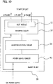
Fig. 10 is a block diagram illustrating a circuit configuration of theinverter unit 50. Theinverter unit 50 includes apower supply circuit 53, aninverter control circuit 54, and aninverter circuit 57. An ignition power supply of the vehicle is supplied to thepower supply circuit 53 and theinverter circuit 57. The power supply circuit converts the voltage of the ignition power supply into a stable 5 V power supply, and supplies the 5 V power supply to theinverter control circuit 54. Theinverter control circuit 54 controls theinverter circuit 57 in accordance with a control signal transmitted from the host device. Theinverter circuit 57 includes theIGBT module 52 described above. - The
power supply circuit 53, theinverter control circuit 54, and theinverter circuit 57 except for theIGBT module 52 are housed in the inverter housing (55 inFig. 1 ). As described above, theIGBT module 52 is housed in the inverter case (51 inFig. 1 ). - Although the example in which the present invention is applied to the
motor 1 has been described, the present invention may be applied to a generator (dynamo). - The present invention is not limited to the above-described embodiment, and a configuration different from the embodiment can be adopted within a range where the configuration of the present invention can be applied. The present invention has unique effects for each aspect described below.
- A first aspect is an electric device including a housing (for example, the inverter housing 55) and a cover (for example, the inverter cover 51) that covers an opening of the housing, or a first housing (for example, the motor housing 3) and a second housing (for example, the inverter housing 55), each of the housing and the cover, or each of the first housing and the second housing including a joint surface (for example, the joint surface 3b and the joint surface 55a, or the second joint surface 55c and the joint surface 51a) to be joined to each other, and a liquid path (for example, the refrigerant flow paths 3a, 55b, and 51b) serving as a refrigerant flow path, each liquid path being opened as a communication port at the joint surface and communicating with each other; and a sealing material (for example, the sealing material 40 and the second sealing material 42) interposed between each joint surface, and an O-ring (for example, the O-ring 39 and the second O-ring 56), wherein the O-ring is interposed between the housing and the cover or between the first housing and the second housing, and is disposed to surround each communication port of each liquid path communicating with each other, and at least one of the housing and the cover or at least one of the first housing and the second housing includes a groove (for example, the groove 3d and the second groove 55e) disposed between the sealing material and the O-ring on the joint surface in a surface direction of the joint surface.
- According to the first aspect of such a configuration, refrigerant leakage from the joint portion between the housing and the cover or the joint portion between the first housing and the second housing can be suppressed by the O-ring. In addition, according to the first aspect, the groove disposed on the joint surface of at least one of the housing and the cover or the joint surface of at least one of the first housing and the second housing suppresses adhesion of the liquid gasket to the O-ring, so that deterioration of the O-ring due to adhesion of the liquid gasket can be suppressed. Furthermore, according to the first aspect, the sealing material, which is a dry body of the liquid gasket interposed between the joint surfaces of the housing and the cover or the joint surfaces of the first housing and the second housing, can enhance the airtightness of the housing and the cover or the first housing and the second housing at low cost.
- A second aspect includes the configuration of the first aspect, wherein the housing includes an inverter housing that houses a control substrate, and the cover includes an inverter cover that closes an opening of the inverter housing.
- According to such a configuration, refrigerant leakage from the joint portion between the inverter housing and the inverter cover can be suppressed by the O-ring, deterioration of the O-ring due to adhesion of the liquid gasket can be suppressed, and airtightness of the inverter housing and the inverter cover can be suppressed at low cost.
- A third aspect is a motor as the electric device according to the configuration of the first aspect, wherein the first housing includes a motor housing that houses a shaft, a rotor, and a stator, and the second housing includes an inverter housing that houses a control substrate.
- According to the third aspect, the deterioration of the O-ring due to the adhesion of the liquid gasket can be suppressed while suppressing the refrigerant leakage from the joint portion between the motor housing and the inverter housing by the O-ring. In addition, according to the third aspect, the airtightness of each of the motor housing and the inverter housing can be enhanced at low cost.
- A fourth aspect is a motor according to the configuration of the third aspect, the motor including: an inverter cover that closes an opening of the inverter housing, each of the inverter housing and the inverter cover including a joint surface joined to each other and a liquid path serving as a refrigerant flow path, each liquid path of the inverter housing and the inverter cover being opened as a communication port at the joint surface and communicating with each other, wherein a second sealing material (for example, the second sealing material 42) and a second O-ring (for example, the second O-ring 56) interposed between the joint surface of the inverter housing and the joint surface of the inverter cover are disposed, the O-ring is disposed to surround each of the communication port of the inverter housing and the communication port of the inverter cover that communicate with each other, and at least one of the inverter housing and the inverter cover includes a second groove disposed between the second sealing material and the second O-ring on the joint surface in a surface direction of the joint surface.
- According to the fourth aspect, for each of the joint portion between the motor housing and the inverter housing and the joint portion between the inverter housing and the inverter cover, refrigerant leakage from the joint portion can be suppressed by the O-ring and the second O-ring. Furthermore, according to the fourth aspect, the deterioration of the O-ring and the second O-ring due to the adhesion of the liquid gasket can be suppressed for each of the two connection portions, and the airtightness of the motor housing, the inverter housing, and the inverter cover can be suppressed at low cost.
- A fifth aspect is the electric device according to the first aspect, wherein the groove has an arcuate shape curved with a curvature concentric with an annular groove (for example, the
annular groove 3e) in which the O-ring is set. - According to the fifth aspect, since the groove can be arranged in a longer form as compared with the configuration in which the shape of the groove is linear, it is possible to further increase the capacity inside the groove and suppress overflow of the liquid gasket from the groove.
- The present invention claims priority based on
Japanese Patent Application No. 2020-049262 filed on March 19, 2020 -
- 1
- motor (electric device)
- 2
- motor unit
- 3
- motor housing (first housing)
- 3a
- refrigerant flow path (liquid path)
- 3a1
- communication port
- 3b
- joint surface
- 3c
- hollow
- 3d
- groove
- 3e
- annular groove
- 5
- stator
- 5a
- stator core
- 5b
- flat wire coil (winding)
- 6
- shaft
- 7
- rotor
- 39
- O-ring
- 40
- sealing material
- 42
- second sealing material
- 50
- inverter unit
- 51
- inverter cover (cover)
- 51a
- joint surface
- 51b
- refrigerant flow path
- 51b1
- joint surface
- 52
- IGBT module
- 55
- inverter housing (housing, second housing)
- 55a
- joint surface
- 55b
- refrigerant flow path
- 55b1
- communication port
- 55b2
- second communication port
- 55c
- second joint surface
- 55e
- second groove
- 56
- second O-ring
Claims (5)
- An electric device comprising:a housing and a cover that covers an opening of the housing, or a first housing and a second housing,each of the housing and the cover, or each of the first housing and the second housing including a joint surface to be joined to each other, and a liquid path serving as a refrigerant flow path,each liquid path being opened as a communication port at the joint surface and communicating with each other; anda sealing material interposed between each joint surface, and an O-ring, whereinthe O-ring is interposed between the housing and the cover or between the first housing and the second housing, and is disposed to surround each communication port of each liquid path communicating with each other, andat least one of the housing and the cover or at least one of the first housing and the second housing includes a groove disposed between the sealing material and the O-ring on the joint surface in a surface direction of the joint surface.
- The electric device according to claim 1, whereinthe housing includes an inverter housing that houses a control substrate, andthe cover includes an inverter cover that closes an opening of the inverter housing.
- A motor as the electric device according to claim 1, whereinthe first housing includes a motor housing that houses a shaft, a rotor, and a stator, andthe second housing includes an inverter housing that houses a control substrate.
- The motor according to claim 3, comprisingan inverter cover that closes an opening of the inverter housing,each of the inverter housing and the inverter cover including a joint surface joined to each other and a liquid path serving as a refrigerant flow path,each liquid path of the inverter housing and the inverter cover being opened as a communication port at the joint surface and communicating with each other, whereina second sealing material and a second O-ring interposed between the joint surface of the inverter housing and the joint surface of the inverter cover are disposed,the O-ring is disposed to surround each of the communication port of the inverter housing and the communication port of the inverter cover that communicate with each other, andat least one of the inverter housing and the inverter cover includes a second groove disposed between the second sealing material and the second O-ring on the joint surface in a surface direction of the joint surface.
- The electric device according to claim 1, wherein
the groove has an arcuate shape curved with a curvature concentric with an annular groove in which the O-ring is set.
Applications Claiming Priority (2)
| Application Number | Priority Date | Filing Date | Title |
|---|---|---|---|
| JP2020049262 | 2020-03-19 | ||
| PCT/JP2021/009178 WO2021187222A1 (en) | 2020-03-19 | 2021-03-09 | Electric machine and motor |
Publications (3)
| Publication Number | Publication Date |
|---|---|
| EP4102688A1 true EP4102688A1 (en) | 2022-12-14 |
| EP4102688A4 EP4102688A4 (en) | 2024-02-28 |
| EP4102688B1 EP4102688B1 (en) | 2025-12-10 |
Family
ID=77771266
Family Applications (1)
| Application Number | Title | Priority Date | Filing Date |
|---|---|---|---|
| EP21771842.8A Active EP4102688B1 (en) | 2020-03-19 | 2021-03-09 | Electric machine and motor |
Country Status (5)
| Country | Link |
|---|---|
| US (1) | US11804750B2 (en) |
| EP (1) | EP4102688B1 (en) |
| JP (1) | JP6940031B1 (en) |
| CN (1) | CN115298937B (en) |
| WO (1) | WO2021187222A1 (en) |
Families Citing this family (2)
| Publication number | Priority date | Publication date | Assignee | Title |
|---|---|---|---|---|
| FR3155664A1 (en) * | 2023-11-16 | 2025-05-23 | Valeo Embrayages | Cooling circuit for electric machine |
| JP7726261B2 (en) * | 2023-12-14 | 2025-08-20 | 株式会社明電舎 | Rotating electric machine assembly |
Family Cites Families (10)
| Publication number | Priority date | Publication date | Assignee | Title |
|---|---|---|---|---|
| JP4382403B2 (en) | 2003-07-07 | 2009-12-16 | 日立建機株式会社 | Hydraulic device |
| JP2006197781A (en) | 2005-01-17 | 2006-07-27 | Fuji Heavy Ind Ltd | Inverter-integrated electric motor unit |
| DE112012003901B4 (en) * | 2011-09-20 | 2022-05-05 | Mitsubishi Electric Corp. | Mechanically and electrically integrated module |
| JP2016049000A (en) | 2014-08-28 | 2016-04-07 | Ntn株式会社 | In-wheel motor driving device |
| CA3158806C (en) * | 2015-02-03 | 2025-10-07 | RCM Enterprise, LLC | Bio-mechanical prosthetic finger with h-shaped rocker |
| JP6631021B2 (en) | 2015-03-18 | 2020-01-15 | 日産自動車株式会社 | Rotating electric machine structure |
| KR20180134348A (en) * | 2016-04-12 | 2018-12-18 | 티엠4 인코포레이티드 | Liquid-cooled electric machine with sealed stator |
| CN109428442A (en) * | 2017-08-28 | 2019-03-05 | 中车株洲电力机车研究所有限公司 | Cooling device |
| JP6977495B2 (en) * | 2017-11-14 | 2021-12-08 | トヨタ自動車株式会社 | Power control device and its in-vehicle structure |
| CN109412348B (en) * | 2018-09-20 | 2019-12-27 | 江苏苏美达五金工具有限公司 | Double-layer electric shock prevention water-cooled motor, motor pump unit and high-pressure cleaning equipment |
-
2021
- 2021-03-09 JP JP2021518210A patent/JP6940031B1/en active Active
- 2021-03-09 WO PCT/JP2021/009178 patent/WO2021187222A1/en not_active Ceased
- 2021-03-09 EP EP21771842.8A patent/EP4102688B1/en active Active
- 2021-03-09 CN CN202180022122.9A patent/CN115298937B/en active Active
- 2021-03-09 US US17/912,285 patent/US11804750B2/en active Active
Also Published As
| Publication number | Publication date |
|---|---|
| JP6940031B1 (en) | 2021-09-22 |
| US11804750B2 (en) | 2023-10-31 |
| EP4102688A4 (en) | 2024-02-28 |
| JPWO2021187222A1 (en) | 2021-09-23 |
| EP4102688B1 (en) | 2025-12-10 |
| WO2021187222A1 (en) | 2021-09-23 |
| US20230131087A1 (en) | 2023-04-27 |
| CN115298937A (en) | 2022-11-04 |
| CN115298937B (en) | 2023-05-09 |
Similar Documents
| Publication | Publication Date | Title |
|---|---|---|
| CN108336848B (en) | Apparatus for sealing a plurality of grooves of a stator of an electric drive | |
| US20110169352A1 (en) | Motor and vehicle | |
| JP6964734B1 (en) | Rotating machine | |
| EP0967707A2 (en) | Divisible lamination brushless pump-motor having fluid cooling system | |
| CN112956118A (en) | Electric machine with fluid cooling | |
| EP4102688B1 (en) | Electric machine and motor | |
| US20230043493A1 (en) | Electric Machine and Motor Vehicle | |
| JP2021151101A (en) | Electrical device and motor | |
| JP2010041854A (en) | Electric motor | |
| JP2014014243A (en) | Brushless motor | |
| JP2002500499A (en) | Drive mechanism for pump | |
| CN118489203B (en) | Rotating Machine | |
| JP2010041853A (en) | Electric motor | |
| JP2010028901A (en) | Electric motor | |
| JP5102130B2 (en) | Fan motor for cooling radiators of automobiles | |
| JP7250087B1 (en) | Rotating electric machine and its manufacturing method | |
| KR20210094526A (en) | rotor assembly | |
| JP7578149B2 (en) | Housing structure for rotating electrical equipment | |
| CN222996387U (en) | A liquid-cooled outer rotor hub motor | |
| US12483087B2 (en) | Rotary electrical machine | |
| JP5704388B2 (en) | Fluid pump | |
| JP2025083656A (en) | Control device integrated rotating electric machine | |
| US20240048026A1 (en) | Brushless electric motor with a membrane for regulating internal pressure | |
| JP2023041388A (en) | Electric apparatus and motor | |
| CN119093665A (en) | Immersion cooling oil ring and motor |
Legal Events
| Date | Code | Title | Description |
|---|---|---|---|
| STAA | Information on the status of an ep patent application or granted ep patent |
Free format text: STATUS: THE INTERNATIONAL PUBLICATION HAS BEEN MADE |
|
| PUAI | Public reference made under article 153(3) epc to a published international application that has entered the european phase |
Free format text: ORIGINAL CODE: 0009012 |
|
| STAA | Information on the status of an ep patent application or granted ep patent |
Free format text: STATUS: REQUEST FOR EXAMINATION WAS MADE |
|
| 17P | Request for examination filed |
Effective date: 20220909 |
|
| AK | Designated contracting states |
Kind code of ref document: A1 Designated state(s): AL AT BE BG CH CY CZ DE DK EE ES FI FR GB GR HR HU IE IS IT LI LT LU LV MC MK MT NL NO PL PT RO RS SE SI SK SM TR |
|
| DAV | Request for validation of the european patent (deleted) | ||
| DAX | Request for extension of the european patent (deleted) | ||
| A4 | Supplementary search report drawn up and despatched |
Effective date: 20240129 |
|
| RIC1 | Information provided on ipc code assigned before grant |
Ipc: H02K 11/33 20160101ALI20240123BHEP Ipc: F16J 15/14 20060101ALI20240123BHEP Ipc: F16J 15/10 20060101ALI20240123BHEP Ipc: H02K 5/10 20060101AFI20240123BHEP |
|
| STAA | Information on the status of an ep patent application or granted ep patent |
Free format text: STATUS: EXAMINATION IS IN PROGRESS |
|
| 17Q | First examination report despatched |
Effective date: 20241122 |
|
| GRAP | Despatch of communication of intention to grant a patent |
Free format text: ORIGINAL CODE: EPIDOSNIGR1 |
|
| STAA | Information on the status of an ep patent application or granted ep patent |
Free format text: STATUS: GRANT OF PATENT IS INTENDED |
|
| INTG | Intention to grant announced |
Effective date: 20250708 |
|
| RIN1 | Information on inventor provided before grant (corrected) |
Inventor name: AKIYAMA, HIROMICHI |
|
| GRAS | Grant fee paid |
Free format text: ORIGINAL CODE: EPIDOSNIGR3 |
|
| GRAA | (expected) grant |
Free format text: ORIGINAL CODE: 0009210 |
|
| STAA | Information on the status of an ep patent application or granted ep patent |
Free format text: STATUS: THE PATENT HAS BEEN GRANTED |
|
| AK | Designated contracting states |
Kind code of ref document: B1 Designated state(s): AL AT BE BG CH CY CZ DE DK EE ES FI FR GB GR HR HU IE IS IT LI LT LU LV MC MK MT NL NO PL PT RO RS SE SI SK SM TR |
|
| REG | Reference to a national code |
Ref country code: CH Ref legal event code: F10 Free format text: ST27 STATUS EVENT CODE: U-0-0-F10-F00 (AS PROVIDED BY THE NATIONAL OFFICE) Effective date: 20251210 Ref country code: GB Ref legal event code: FG4D |
|
| REG | Reference to a national code |
Ref country code: DE Ref legal event code: R096 Ref document number: 602021044173 Country of ref document: DE |
|
| REG | Reference to a national code |
Ref country code: IE Ref legal event code: FG4D |
|
| PG25 | Lapsed in a contracting state [announced via postgrant information from national office to epo] |
Ref country code: ES Free format text: LAPSE BECAUSE OF FAILURE TO SUBMIT A TRANSLATION OF THE DESCRIPTION OR TO PAY THE FEE WITHIN THE PRESCRIBED TIME-LIMIT Effective date: 20251210 |
|
| REG | Reference to a national code |
Ref country code: LT Ref legal event code: MG9D |
|
| PG25 | Lapsed in a contracting state [announced via postgrant information from national office to epo] |
Ref country code: NO Free format text: LAPSE BECAUSE OF FAILURE TO SUBMIT A TRANSLATION OF THE DESCRIPTION OR TO PAY THE FEE WITHIN THE PRESCRIBED TIME-LIMIT Effective date: 20260310 |
|
| PG25 | Lapsed in a contracting state [announced via postgrant information from national office to epo] |
Ref country code: FI Free format text: LAPSE BECAUSE OF FAILURE TO SUBMIT A TRANSLATION OF THE DESCRIPTION OR TO PAY THE FEE WITHIN THE PRESCRIBED TIME-LIMIT Effective date: 20251210 Ref country code: HR Free format text: LAPSE BECAUSE OF FAILURE TO SUBMIT A TRANSLATION OF THE DESCRIPTION OR TO PAY THE FEE WITHIN THE PRESCRIBED TIME-LIMIT Effective date: 20251210 |
|
| REG | Reference to a national code |
Ref country code: NL Ref legal event code: MP Effective date: 20251210 |
|
| PG25 | Lapsed in a contracting state [announced via postgrant information from national office to epo] |
Ref country code: RS Free format text: LAPSE BECAUSE OF FAILURE TO SUBMIT A TRANSLATION OF THE DESCRIPTION OR TO PAY THE FEE WITHIN THE PRESCRIBED TIME-LIMIT Effective date: 20260310 |
|
| PGFP | Annual fee paid to national office [announced via postgrant information from national office to epo] |
Ref country code: FR Payment date: 20260323 Year of fee payment: 6 |
|
| PG25 | Lapsed in a contracting state [announced via postgrant information from national office to epo] |
Ref country code: LV Free format text: LAPSE BECAUSE OF FAILURE TO SUBMIT A TRANSLATION OF THE DESCRIPTION OR TO PAY THE FEE WITHIN THE PRESCRIBED TIME-LIMIT Effective date: 20251210 |