EP4102663A1 - Mounting assembly for electrical busway - Google Patents
Mounting assembly for electrical busway Download PDFInfo
- Publication number
- EP4102663A1 EP4102663A1 EP22175170.4A EP22175170A EP4102663A1 EP 4102663 A1 EP4102663 A1 EP 4102663A1 EP 22175170 A EP22175170 A EP 22175170A EP 4102663 A1 EP4102663 A1 EP 4102663A1
- Authority
- EP
- European Patent Office
- Prior art keywords
- mounting bracket
- electrical busway
- mounting
- beam member
- busway
- Prior art date
- Legal status (The legal status is an assumption and is not a legal conclusion. Google has not performed a legal analysis and makes no representation as to the accuracy of the status listed.)
- Granted
Links
Images



Classifications
-
- H—ELECTRICITY
- H02—GENERATION; CONVERSION OR DISTRIBUTION OF ELECTRIC POWER
- H02G—INSTALLATION OF ELECTRIC CABLES OR LINES, OR OF COMBINED OPTICAL AND ELECTRIC CABLES OR LINES
- H02G5/00—Installations of bus-bars
- H02G5/06—Totally-enclosed installations, e.g. in metal casings
-
- H—ELECTRICITY
- H02—GENERATION; CONVERSION OR DISTRIBUTION OF ELECTRIC POWER
- H02G—INSTALLATION OF ELECTRIC CABLES OR LINES, OR OF COMBINED OPTICAL AND ELECTRIC CABLES OR LINES
- H02G1/00—Methods or apparatus specially adapted for installing, maintaining, repairing or dismantling electric cables or lines
-
- H—ELECTRICITY
- H02—GENERATION; CONVERSION OR DISTRIBUTION OF ELECTRIC POWER
- H02G—INSTALLATION OF ELECTRIC CABLES OR LINES, OR OF COMBINED OPTICAL AND ELECTRIC CABLES OR LINES
- H02G3/00—Installations of electric cables or lines or protective tubing therefor in or on buildings, equivalent structures or vehicles
- H02G3/26—Installations of cables, lines, or separate protective tubing therefor directly on or in walls, ceilings, or floors
- H02G3/263—Installation, e.g. suspension, of conduit channels or other supports
-
- H—ELECTRICITY
- H02—GENERATION; CONVERSION OR DISTRIBUTION OF ELECTRIC POWER
- H02G—INSTALLATION OF ELECTRIC CABLES OR LINES, OR OF COMBINED OPTICAL AND ELECTRIC CABLES OR LINES
- H02G5/00—Installations of bus-bars
- H02G5/02—Open installations
- H02G5/025—Supporting structures
-
- H—ELECTRICITY
- H02—GENERATION; CONVERSION OR DISTRIBUTION OF ELECTRIC POWER
- H02G—INSTALLATION OF ELECTRIC CABLES OR LINES, OR OF COMBINED OPTICAL AND ELECTRIC CABLES OR LINES
- H02G5/00—Installations of bus-bars
- H02G5/005—Laminated bus-bars
Definitions
- the present invention generally relates to mounting arrangements. More particularly the present invention relates to an adjustable mounting assembly with plurality of mounting brackets for electrical busways to mount and subsequently adjust its location manually in line with supporting hanger rod or pendant type beam member. This invention can also find its utility in the field in which an apparatus is required to be adjustably mounted in line with a supporting hanger rod or pendant type beam member.
- brackets will be precisely aligned and fixed with proper dimensions and position in order to make the installation.
- the principal object of this invention to provide a mounting assembly with easy adjustable mounting and positioning of electrical busway.
- the hanging provision for example without any limitations, is a supporting hanger rod or pendant type beam member.
- the present invention provides a mounting assembly for aligning electrical busway, said mounting assembly comprising:
- the first mounting bracket comprises two flat flanges formed at its edges to be slidably secured with said electric busway.
- the second mounting bracket is removably attached with a threaded hanger rod to move the electrical busway along the length of the hanger rod.
- said second mounting bracket is provided with a central hole allowing said hanger rod to pass through said omega profiled slotted hole.
- said third mounting bracket is removably attached with a beam member to move the electrical busway along the length of the beam member, said beam member being a pendant-type beam member.
- said beam member is provided with plurality of screwing holes disposed along its length in a spaced part manner for removably attaching said third mounting bracket.
- said third mounting bracket is provided with a slit-shaped cutout disposed at its center to receive said first mounting bracket.
- said beam member is provided with a flat top surface having a set of screwing holes to attach said beam member with overhead running platforms.
- said third mounting bracket is provided with a pair of stopping flanges attached on the beam member and thereby providing support to the electrical busway.
- Another object of this invention is to provide plurality of mounting brackets, which will ease the assembly process and thereby substantially reduce mounting and positioning time along with labor cost during installation and erection.
- Another object of the invention is to provide a simple in design, easy to make, rugged in construction, easy to fix and efficient in operation.
- the novel mounting assembly aids in easy installation of electrical busways to the wall or roof with minimum tools and resources. As the installation is simple, the time taken for assembly and installation is very low.
- Another object of the present invention is to help the installer to find the right position and orientation with minimal efforts.
- fixation provided in the invented mounting assembly is purely self-aligned, which results in correct position for installation.
- This feature eliminates the improper installation caused by poor dimensions, angularity and unevenness, in turn provides better robustness to system and improves the performance.
- At least one mounting bracket of the mounting assembly is provided with the omega profile providing the easiness to align the electrical busway and the hanging provisions such as supporting hanger rod or pendant type beam member, at the at the right location and it also acts a guide for the intended orientation and installation.
- flanges at the edges of the mounting bracket having omega profile helps to slide the mounting bracket to identify the correct position of the electrical busway.
- the profiles defined with the flanges, of said plurality of mounting bracket, provides the easy guiding path for inserting the electrical busway in flatwise orientation.
- a stopper flange is disposed at the bottom portion of the third mounting bracket having omega profile.
- the stopper flange helps to act as a stopper and thereby providing robust support to the electrical busway.
- two different installation orientation of electrical busway can be adjusted.
- One of the installation orientation of the electrical busway is an edgewise orientation and other one is a flatwise orientation. Both orientations are very commonly used while installing an electrical busway.
- the first mounting bracket is provided for the sliding alignment of the electrical busway.
- the first mounting bracket takes care of sliding of the electrical busway to right or left orientation and locking with the supporting hanger rods or pendant type beam member, for better alignment.
- the first mounting bracket is provided with a slit disposed at its side wall to receive said third mounting bracket.
- present invention provides complete robustness and ease of installation of electrical busway.
- the installer need not consider the improper uneven walls and/or roof, as the omega profiled first mounting bracket along with second and third mounting brackets provide self-aligning function with respect to for better installation.
- the invented mounting assembly (100) is deployed for mounting and subsequently aligning an electrical busway (112) in a edgewise orientation.
- the edges of the busbars (128) within it are in an up and down orientation, and the busbars (128) run horizontally and disposed in a spaced apart manner.
- bolt-on or plug-in units, according to requirement, drawing power from the electrical busway (112) are installed at the top and the bottom of the busbars (128).
- the invented mounting assembly (100) is also deployed for mounting and subsequently aligning in electrical busway (112) in a flatwise orientation.
- the flat side of the busbars (128) are in an up and down orientation, and the busbars (128) disposed vertically in a spaced apart manner.
- the plug-in or bolt-on units, according to requirement, for drawing power are installed at the sides of the electrical busway (112).
- the mounting assembly (100) can aid the above arrangement for electrical elements that have higher loads to be carried and need to be installed either edgewise or flatwise.
- the mounting assembly (100) comprises a first mounting bracket (102), a second mounting bracket (104) and a third mounting bracket (106). At a time, only two mounting brackets are used to mount said electrical busway (112) and align either in edgewise or in flatwise orientation. In edgewise orientation, the first mounting bracket (102) is fastened to C-shaped slots (114) of the electrical busway (112) to slide thereon and the second mounting bracket (104) is fastened on a hanger rod (108) which comes from top running surface such as ceiling or overhead running platforms.
- the first mounting bracket (102) is slidably attached to the electrical busway (112) and provided with omega profiled slotted hole (118) to slide and the third mounting bracket (106) is bolted on the beam member (110) which comes from wall or ceiling.
- the first mounting bracket (102) as seen in figure 6 is common for both edgewise and flatwise orientation, which is slidably attached with the electrical busway (112).
- the first mounting bracket (102) is formed of sheet-like metal having an omega profile with two flanges (116) formed at the edges of a side wall (117) for securing with the electrical busway (112).
- the side wall (117) has slits (126c).
- the flanges (116) are formed to slidably connect with C-shaped slots (114) available on the electrical busway (112).
- the flanges (116) also provide easy guiding path for inserting the electrical busway (112) in both flatwise and edgewise orientation.
- the C-shaped slots (114) provide for a rigid support while the first mounting bracket (102) is assembled either with the second mounting bracket (104) or with the third mounting bracket (106) to hold the electrical busway (112) in position.
- the flanges (116) can be formed having a congruent profile with respect to slots as available in the other electrical equipment that are to be mounted with invented mounting assembly (100).
- the first mounting bracket (102) preferably is in line either with supporting hanger rod (108) or with pendant type beam member (110).
- the hanger rod (108) as shown at least in figure 9(a) and figure 9(c) , provides adequate support in case of edgewise orientation.
- the beam member (110), as shown at least in figures 10(a) and 10(c) is used in case of flatwise orientation.
- the first mounting bracket (102) is further provided with omega profiled slotted hole (118).
- the second mounting bracket (104) as seen in figure 7 is used for edgewise orientation which is engaged with the hanger rod (108).
- the hanger rod (108) is threaded and accordingly said second mounting bracket (104) is provided with a central hole (120) for the hanger rod (108) to pass through.
- the second mounting bracket (104) can be rotated in order to translate along the extension of the hanger rod (108).
- the central hole (120) on the second mounting bracket (104) has such a diameter that the bracket can be moved freely along the hanger rod (108), and then fixed with fasteners (130) at an intended position.
- the electrical busway (112) can be moved along its extension by sliding the first mounting bracket (102) and also along the extension of the hanger rod (108) to reach intended position by translating the second mounting bracket (104) and thereupon alignment is taken care of.
- the omega profiled slotted hole (118) on the first mounting bracket (102) receives the hanger rod (108) and thereupon facilitates robust engagement of the first mounting bracket (102) and the second mounting bracket (104).
- the third mounting bracket (106) as seen in figure 8 is used for flatwise orientation which is to be installed on a beam member (110).
- the beam member (110) as shown in the embodiment of figure 10(a) , is a pendant type beam member.
- the beam member (110) is provided with a flat top surface (132) having a set of screwing holes (134), to attach with a top running surface such as ceiling or overhead running platforms or structures in the building.
- Another set of screwing holes (136) are disposed along the longitudinal extent of the beam member (110) in a spaced apart manner.
- the third mounting bracket (106) can be screwed with the screwing holes (136) and fixed thereon at an intended position.
- the arrangement of the electrical busway (112) and the first mounting bracket (102) is attached with the third mounting bracket (106). Then by the virtue of the first mounting bracket (102), the electrical busway (112) can be translated along its length, say along X-axis. Whereas the vertical alignment, along the Z-axis can be controlled by attaching the third mounting bracket (106) along the length of said beam member (110), thereby controlling its alignment.
- the third mounting bracket (106) is further provided with open omega profiles having a slit-shaped cutout (126) such that, the first mounting bracket (102) can be placed therein.
- an electrical busway (112) is mounted at edgewise and flatwise orientation respectively. While achieving a flatwise or edgewise orientation, initially the first mounting bracket (102) is attached with the electrical busway (112), creating a subassembly as shown in figures 9(b) and 10(b) . This subassembly can then be installed with either the second mounting bracket (104) or the third mounting bracket (106).
- the second mounting bracket (104) is formed as a C-shaped sheet metal to be installed with said hanger rod (108).
- the second mounting bracket (104) is formed of a central region (122), and a pair of arms (124) transversely protruding from opposite edge of the central region (122).
- the central region (122) is generally flat which bends at its opposite edges to form the pair of arms (124).
- the hanger rod (108) goes through the omega profiled slotted hole (118), and the pair of arms (124) comes in contact with the first mounting bracket (102).
- at least two fasteners (130) are screwed over the threaded supporting hanger rod (108).
- the hanger rod (108) in turn bears the load of the electrical busway (112).
- the second mounting bracket (104) is disposed over the first mounting bracket (102) after the right position is found for installation to fix the electrical busway (112) rigidly.
- the supporting hanger rod (108) is a standard rod available at various sizes and material. They are used for installation or hanging of equipment and electrical busways (112) from the wall or roof. The hanger rod (108) could also be suspended over a beam running overhead.
- the fasteners (130) are standard nuts commonly used in any installation site. The fasteners (130) are available in different sizes and materials, and can be chosen according to the choice of the hanger rod (108).
- the third mounting bracket (106) is formed with an omega profile body having a slit-shaped cutout (126) running at the center of the bracket. Through this specific slit-shaped cutout (126), the first mounting bracket (102) is engaged and thereupon the mounting force and weight of electrical busway (112) is supported.
- the third mounting bracket (106) helps an installer to position the electrical busway (112) at a level according to the requirement of the installation site.
- the profile of the slit-shaped cutout (126) on the third mounting bracket (106) also aids in guiding the installation of electrical busway (112) to the intended position in a flatwise orientation.
- a pair of stopping flanges (138) are formed at the bottom portion of the third mounting bracket (106).
- the third bracket (106), as seen in figure 10(a) can be mounted over the beam member (110), or could be fixed directly to the wall.
- the beam member (110), which is a pendant type beam member (110) is used for installation of electrical busway (112) on the wall.
- FIG. 9(a) to 10(d) illustrate a step-by-step mounting procedure of electrical busway (112) with the invented mounting assembly (100) in an edgewise orientation.
- Figures 10(a) to 10(d) illustrate a step-by-step mounting procedure of electrical busway (112) with the invented mounting assembly (100) in a flatwise orientation.
- Step 1 preparation of the installation area as shown in figures 9(a) and 10(a) :
- the installation area is constructed with either the second mounting bracket (104) or the third mounting bracket (106).
- This one bracket (104 or 106) is placed according to the required placement of the electrical busway (112).
- the threaded hanger rod (108) is engaged with second mounting bracket (104), and moved along the Z-axis until the required position is reached.
- the fasteners (130) are screwed over the hanger rod (108) to fix the mounting position of the second mounting bracket (104) along the Z-axis.
- the stopping flange (138) is placed at an intended position on the beam member (110), and screwed thereon using the standard screws.
- one bracket being either second mounting bracket (104) or third mounting bracket (106) and standard fasteners.
- Step 2 Preparation of electrical busway (112) elements to be installed as shown in figures 9(b) and 10(b) :
- the electrical busway (112) is assembled with the first mounting bracket (102).
- the first mounting bracket (102) can traverse along the longitudinal length (L) of the electrical busway (112) to manually adjust its location, which provides complete flexibility to position the electrical busway (112).
- Step 3 Installation of electrical busway (112) as shown in figures 9(c) and 10(c) :
- the electrical busway (112) with first mounting bracket (102) attached therewith can now be inserted to the installation area by locking two brackets.
- One of the brackets being the first mounting bracket (102) and the other one being either second mounting bracket (104) or third mounting bracket (106).
- second mounting bracket (104), attached with the hanger rod (108) is such aligned that it is put over the first mounting bracket (102) and locks thereon.
- the alignment of the third mounting bracket (106) with the first mounting bracket (102) is carried out in such a manner that the first mounting bracket (102) is disposed in-line the slit-shaped cut out (126) as shown in figure 10(c) .
- the first mounting bracket (102) is engaged through the slit-shaped cutout (126).
- Step 4 Fixation of hanging provisions as shown in figures 9(d) and 10(d) :
- Final step is to make a rigid fixation of the electrical busway (112) at an intended alignment and position by adjusting said first mounting bracket (102) with either the second mounting bracket (104) or third mounting bracket (106) and thereupon fastening at right torque with said hanger rod (108) or beam member (110) respectively.
- the electrical busway (112) is rigidly fixed to the hanging provisions, such as supporting hanger rod (108) or pendant type beam member (110).
- Tap-off unit installation can be managed anywhere, without any obstruction.
Landscapes
- Engineering & Computer Science (AREA)
- Architecture (AREA)
- Civil Engineering (AREA)
- Structural Engineering (AREA)
- Installation Of Bus-Bars (AREA)
Abstract
Description
- The present invention generally relates to mounting arrangements. More particularly the present invention relates to an adjustable mounting assembly with plurality of mounting brackets for electrical busways to mount and subsequently adjust its location manually in line with supporting hanger rod or pendant type beam member. This invention can also find its utility in the field in which an apparatus is required to be adjustably mounted in line with a supporting hanger rod or pendant type beam member.
- Existing mounting or hanging system for electrical apparatus like electrical busways do not have the flexibility to allow the fixation without tampering the tap-off unit fixations. The fixation comes around the busway, blocking some space on the front side, which obstructs the tap-off units and other components that could be installed on the busway. The installer has to identify the correct dimension and position before installation. If there is a minor change in dimension or unevenness of the roof or wall, its results in irregular positioning of busway, which increases the stress on the busway connection, and thus provides poor electrical conductivity and performance.
- Existing mounting systems are installed around the electrical apparatus such as electrical busways and occupy the usable space for loads. In general the brackets will be precisely aligned and fixed with proper dimensions and position in order to make the installation.
- In a known mounting assembly, at least three components are used to devise the mechanism of mounting electrical busways. Further, it doesn't provide flexibility to adjust the sliding of busway for correct position. Disadvantageously, in the existing mounting assembly only a single orientation of the electrical busway is managed with the mounting brackets.
- Furthermore, in the existing technique for mounting electrical busways, it is very complex to assemble the mounting apparatus with the electrical busways. There exists no such mounting assembly known to any installer for attaching the busway the thereby adjust position and orientation of the electrical busways with minimum tools and efforts.
- Therefore, existing mounting assembly with brackets requires complex mounting technique which is prone to create challenge for an installer such as:
- brackets installed around the electrical busway;
- not compatible with the functioning of continuous busway;
- does not provide the flexibility for easy alignment;
- no provision for installer to align without looking at the rear side.
- With a view therefore to the problems associated with the existing mounting systems and methods for electrical busways, the inventors felt to need to devise a novel mounting assembly comprising plurality of mounting brackets for mounting and subsequently arrange and adjust the orientation of the electrical busway. With at least one mounting bracket having omega profiled slotted holes, two different orientation of the electrical busway can be easily adjusted.
- It is, therefore, the principal object of this invention to provide a mounting assembly with easy adjustable mounting and positioning of electrical busway. The hanging provision, for example without any limitations, is a supporting hanger rod or pendant type beam member.
- Accordingly, the present invention provides a mounting assembly for aligning electrical busway, said mounting assembly comprising:
- a first mounting bracket slidably attached to said electrical busway,
- a second mounting bracket removably attached with a supporting hanger rod, and
- a third mounting bracket removably attached with a supporting beam member
- According to one embodiment of the invention, the first mounting bracket comprises two flat flanges formed at its edges to be slidably secured with said electric busway.
- According to one embodiment of the invention, the second mounting bracket is removably attached with a threaded hanger rod to move the electrical busway along the length of the hanger rod.
- According to one embodiment of the invention, said second mounting bracket is provided with a central hole allowing said hanger rod to pass through said omega profiled slotted hole.
- According to one embodiment of the invention, said third mounting bracket is removably attached with a beam member to move the electrical busway along the length of the beam member, said beam member being a pendant-type beam member.
- According to one embodiment of the invention, said beam member is provided with plurality of screwing holes disposed along its length in a spaced part manner for removably attaching said third mounting bracket.
- According to one embodiment of the invention, said third mounting bracket is provided with a slit-shaped cutout disposed at its center to receive said first mounting bracket.
- According to one embodiment of the invention, said beam member is provided with a flat top surface having a set of screwing holes to attach said beam member with overhead running platforms.
- According to one embodiment of the invention, said third mounting bracket is provided with a pair of stopping flanges attached on the beam member and thereby providing support to the electrical busway.
- Another object of this invention is to provide plurality of mounting brackets, which will ease the assembly process and thereby substantially reduce mounting and positioning time along with labor cost during installation and erection.
- Another object of the invention is to provide a simple in design, easy to make, rugged in construction, easy to fix and efficient in operation.
- According to one object of the present invention the novel mounting assembly aids in easy installation of electrical busways to the wall or roof with minimum tools and resources. As the installation is simple, the time taken for assembly and installation is very low.
- According to one embodiment of the invention, good flexibility is provided to have the tap-off units installed anywhere over the electrical busway, the invention will not block usable space which are dedicated for connecting the loads.
- Another object of the present invention is to help the installer to find the right position and orientation with minimal efforts.
- According to one embodiment of the invention, fixation provided in the invented mounting assembly is purely self-aligned, which results in correct position for installation. This feature eliminates the improper installation caused by poor dimensions, angularity and unevenness, in turn provides better robustness to system and improves the performance.
- According to one embodiment of the invention, at least one mounting bracket of the mounting assembly is provided with the omega profile providing the easiness to align the electrical busway and the hanging provisions such as supporting hanger rod or pendant type beam member, at the at the right location and it also acts a guide for the intended orientation and installation.
- According to one embodiment of the invention, flanges at the edges of the mounting bracket having omega profile helps to slide the mounting bracket to identify the correct position of the electrical busway. The profiles defined with the flanges, of said plurality of mounting bracket, provides the easy guiding path for inserting the electrical busway in flatwise orientation.
- According to one embodiment of the invention, a stopper flange is disposed at the bottom portion of the third mounting bracket having omega profile. The stopper flange helps to act as a stopper and thereby providing robust support to the electrical busway.
- According to one object of the invention, by aid of the first mounting bracket having omega profiled slotted holes, two different installation orientation of electrical busway can be adjusted. One of the installation orientation of the electrical busway is an edgewise orientation and other one is a flatwise orientation. Both orientations are very commonly used while installing an electrical busway.
- According to one object of the invention, the first mounting bracket is provided for the sliding alignment of the electrical busway. The first mounting bracket takes care of sliding of the electrical busway to right or left orientation and locking with the supporting hanger rods or pendant type beam member, for better alignment.
- According to one object of the invention, the first mounting bracket is provided with a slit disposed at its side wall to receive said third mounting bracket.
- With all these features, present invention provides complete robustness and ease of installation of electrical busway. The installer need not consider the improper uneven walls and/or roof, as the omega profiled first mounting bracket along with second and third mounting brackets provide self-aligning function with respect to for better installation.
- For better understanding, an illustrative embodiment of the invention will now be described with reference to the accompanying drawings. It will however be appreciated that the embodiment exemplified in the drawings are merely illustrative and not limitative to the scope of the invention, because it is quite possible, indeed often desirable, to introduce a number of variations in the embodiment that have been shown in the drawings. In the accompanying drawings:
-
Figures 1(a) and 1(b) depict perspective view of the existing mounting apparatus for electrical busway. -
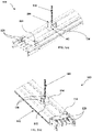
Figure 2(a) is a perspective view of the invented mounting assembly attached with electrical busway in an edgewise orientation. -
Figure 2(b) is another perspective view of the invented mounting assembly attached with electrical busway in an edgewise orientation as shown infigure 2(a) . -
Figure 3(a) is a perspective view of the invented mounting assembly attached with electrical busway in a flatwise orientation. -
Figure 3(b) is another perspective view of the invented mounting assembly attached with electrical busway in a flatwise orientation as shown infigure 3(a) . -
Figure 4 is a perspective view of the invented mounting assembly disengaged from electrical busway in an edgewise orientation. -
Figure 5 is a perspective view of the invented mounting assembly disengaged from electrical busway in a flatwise orientation. -
Figure 6 is a perspective view a first mounting bracket of the invented mounting assembly according to one embodiment of the invention. -
Figure 7 is a perspective view a second mounting bracket of the invented mounting assembly according to one embodiment of the invention. -
Figure 8 is a perspective view a third mounting bracket of the invented mounting assembly according to one embodiment of the invention. -
Figures 9(a) to 9(d) illustrate the mounting procedure of the invented mounting assembly with electrical busway in an edgewise orientation. -
Figures 10(a) to 10(d) illustrate the mounting procedure of the invented mounting assembly with electrical busway in a flatwise orientation. - In the following, numerous specific details are set forth to provide a thorough description of embodiment. Those skilled in the art will recognize and appreciate that, despite of the detailed nature of the exemplary embodiment provided herein; changes and modifications may be applied to said embodiment without limiting or departing from the generally intended scope.
- As seen in
figures 2(a) and 2(b) the invented mounting assembly (100) is deployed for mounting and subsequently aligning an electrical busway (112) in a edgewise orientation. In the edgewise orientation of the electrical busway (112), the edges of the busbars (128) within it are in an up and down orientation, and the busbars (128) run horizontally and disposed in a spaced apart manner. In this orientation, bolt-on or plug-in units, according to requirement, drawing power from the electrical busway (112) are installed at the top and the bottom of the busbars (128). With reference tofigures 3(a) and 3(b) the invented mounting assembly (100) is also deployed for mounting and subsequently aligning in electrical busway (112) in a flatwise orientation. In the flatwise orientation of the electrical busway (112), the flat side of the busbars (128) are in an up and down orientation, and the busbars (128) disposed vertically in a spaced apart manner. In this orientation, the plug-in or bolt-on units, according to requirement, for drawing power, are installed at the sides of the electrical busway (112). According to another object of the invention, the mounting assembly (100) can aid the above arrangement for electrical elements that have higher loads to be carried and need to be installed either edgewise or flatwise. - The mounting assembly (100), as shown in the accompanying figures, comprises a first mounting bracket (102), a second mounting bracket (104) and a third mounting bracket (106). At a time, only two mounting brackets are used to mount said electrical busway (112) and align either in edgewise or in flatwise orientation. In edgewise orientation, the first mounting bracket (102) is fastened to C-shaped slots (114) of the electrical busway (112) to slide thereon and the second mounting bracket (104) is fastened on a hanger rod (108) which comes from top running surface such as ceiling or overhead running platforms. In a flatwise orientation, the first mounting bracket (102) is slidably attached to the electrical busway (112) and provided with omega profiled slotted hole (118) to slide and the third mounting bracket (106) is bolted on the beam member (110) which comes from wall or ceiling.
- The first mounting bracket (102) as seen in
figure 6 , is common for both edgewise and flatwise orientation, which is slidably attached with the electrical busway (112). According to specific embodiment as seen in thefigure 6 , the first mounting bracket (102) is formed of sheet-like metal having an omega profile with two flanges (116) formed at the edges of a side wall (117) for securing with the electrical busway (112). The side wall (117) has slits (126c). The flanges (116), according to one preferred embodiment, are formed to slidably connect with C-shaped slots (114) available on the electrical busway (112). The flanges (116) also provide easy guiding path for inserting the electrical busway (112) in both flatwise and edgewise orientation. - The C-shaped slots (114) provide for a rigid support while the first mounting bracket (102) is assembled either with the second mounting bracket (104) or with the third mounting bracket (106) to hold the electrical busway (112) in position. Alternatively, the flanges (116) can be formed having a congruent profile with respect to slots as available in the other electrical equipment that are to be mounted with invented mounting assembly (100). With this provision, the first mounting bracket (102), preferably is in line either with supporting hanger rod (108) or with pendant type beam member (110). The hanger rod (108), as shown at least in
figure 9(a) andfigure 9(c) , provides adequate support in case of edgewise orientation. The beam member (110), as shown at least infigures 10(a) and10(c) , is used in case of flatwise orientation. The first mounting bracket (102) is further provided with omega profiled slotted hole (118). - The second mounting bracket (104) as seen in
figure 7 , is used for edgewise orientation which is engaged with the hanger rod (108). The hanger rod (108), according to a preferred embodiment, is threaded and accordingly said second mounting bracket (104) is provided with a central hole (120) for the hanger rod (108) to pass through. As the threaded provision of the hanger rod (108) is disposed in a helical manner, the second mounting bracket (104) can be rotated in order to translate along the extension of the hanger rod (108). Alternatively, the central hole (120) on the second mounting bracket (104) has such a diameter that the bracket can be moved freely along the hanger rod (108), and then fixed with fasteners (130) at an intended position. - When the second mounting bracket (104) is disposed onto the first mounting bracket (102) and attached using said fasteners (130). The electrical busway (112) can be moved along its extension by sliding the first mounting bracket (102) and also along the extension of the hanger rod (108) to reach intended position by translating the second mounting bracket (104) and thereupon alignment is taken care of. The omega profiled slotted hole (118) on the first mounting bracket (102) receives the hanger rod (108) and thereupon facilitates robust engagement of the first mounting bracket (102) and the second mounting bracket (104).
- The third mounting bracket (106) as seen in
figure 8 , is used for flatwise orientation which is to be installed on a beam member (110). The beam member (110), as shown in the embodiment offigure 10(a) , is a pendant type beam member. The beam member (110) is provided with a flat top surface (132) having a set of screwing holes (134), to attach with a top running surface such as ceiling or overhead running platforms or structures in the building. Another set of screwing holes (136) are disposed along the longitudinal extent of the beam member (110) in a spaced apart manner. The third mounting bracket (106) can be screwed with the screwing holes (136) and fixed thereon at an intended position. - The arrangement of the electrical busway (112) and the first mounting bracket (102) is attached with the third mounting bracket (106). Then by the virtue of the first mounting bracket (102), the electrical busway (112) can be translated along its length, say along X-axis. Whereas the vertical alignment, along the Z-axis can be controlled by attaching the third mounting bracket (106) along the length of said beam member (110), thereby controlling its alignment. With reference to
figures 8 and10(c) of the accompanying drawings, the third mounting bracket (106), is further provided with open omega profiles having a slit-shaped cutout (126) such that, the first mounting bracket (102) can be placed therein. - With reference to
figures 4 and 5 , an electrical busway (112) is mounted at edgewise and flatwise orientation respectively. While achieving a flatwise or edgewise orientation, initially the first mounting bracket (102) is attached with the electrical busway (112), creating a subassembly as shown infigures 9(b) and10(b) . This subassembly can then be installed with either the second mounting bracket (104) or the third mounting bracket (106). - With reference to
figures 4 and7 , the second mounting bracket (104) is formed as a C-shaped sheet metal to be installed with said hanger rod (108). The second mounting bracket (104) is formed of a central region (122), and a pair of arms (124) transversely protruding from opposite edge of the central region (122). The central region (122) is generally flat which bends at its opposite edges to form the pair of arms (124). While mounting the electrical busway (112), the hanger rod (108) goes through the omega profiled slotted hole (118), and the pair of arms (124) comes in contact with the first mounting bracket (102). To provide a rigid support, at least two fasteners (130) are screwed over the threaded supporting hanger rod (108). The hanger rod (108), in turn bears the load of the electrical busway (112). The second mounting bracket (104) is disposed over the first mounting bracket (102) after the right position is found for installation to fix the electrical busway (112) rigidly. - The supporting hanger rod (108) is a standard rod available at various sizes and material. They are used for installation or hanging of equipment and electrical busways (112) from the wall or roof. The hanger rod (108) could also be suspended over a beam running overhead. The fasteners (130) are standard nuts commonly used in any installation site. The fasteners (130) are available in different sizes and materials, and can be chosen according to the choice of the hanger rod (108).
- The third mounting bracket (106), as depicted in
figure 8 , is formed with an omega profile body having a slit-shaped cutout (126) running at the center of the bracket. Through this specific slit-shaped cutout (126), the first mounting bracket (102) is engaged and thereupon the mounting force and weight of electrical busway (112) is supported. The third mounting bracket (106) helps an installer to position the electrical busway (112) at a level according to the requirement of the installation site. The profile of the slit-shaped cutout (126) on the third mounting bracket (106) also aids in guiding the installation of electrical busway (112) to the intended position in a flatwise orientation. Further, a pair of stopping flanges (138) are formed at the bottom portion of the third mounting bracket (106). The stopping flanges (138), rest on the beam member (110), and thereby aid in providing robust support to the electrical busway (112). The third bracket (106), as seen infigure 10(a) , can be mounted over the beam member (110), or could be fixed directly to the wall. The beam member (110), which is a pendant type beam member (110) is used for installation of electrical busway (112) on the wall. - The installation process of the electrical busway (112) with the aid of the invented mounting assembly (100) is illustrated in figures from 9(a) to 10(d).
Figures 9(a) to 9(d) illustrate a step-by-step mounting procedure of electrical busway (112) with the invented mounting assembly (100) in an edgewise orientation.Figures 10(a) to 10(d) illustrate a step-by-step mounting procedure of electrical busway (112) with the invented mounting assembly (100) in a flatwise orientation. - Step 1: preparation of the installation area as shown in
figures 9(a) and10(a) : Depending on the requirement of the orientation of the electrical busway (112), the installation area is constructed with either the second mounting bracket (104) or the third mounting bracket (106). As this one bracket (104 or 106), is placed according to the required placement of the electrical busway (112). The threaded hanger rod (108), as illustrated infigure 9(a) , is engaged with second mounting bracket (104), and moved along the Z-axis until the required position is reached. The fasteners (130) are screwed over the hanger rod (108) to fix the mounting position of the second mounting bracket (104) along the Z-axis. As for the third mounting bracket (106) shown infigure 10(a) , the stopping flange (138) is placed at an intended position on the beam member (110), and screwed thereon using the standard screws. Thus, it is conveniently managed by one bracket, being either second mounting bracket (104) or third mounting bracket (106) and standard fasteners. - Step 2: Preparation of electrical busway (112) elements to be installed as shown in
figures 9(b) and10(b) : The electrical busway (112) is assembled with the first mounting bracket (102). As two flanges (116) formed at the edges of said first mounting bracket (102) slidably engage with electrical busway (112). The first mounting bracket (102) can traverse along the longitudinal length (L) of the electrical busway (112) to manually adjust its location, which provides complete flexibility to position the electrical busway (112). - Step 3: Installation of electrical busway (112) as shown in
figures 9(c) and10(c) : The electrical busway (112) with first mounting bracket (102) attached therewith can now be inserted to the installation area by locking two brackets. One of the brackets being the first mounting bracket (102) and the other one being either second mounting bracket (104) or third mounting bracket (106). As shown infigure 9(c) , second mounting bracket (104), attached with the hanger rod (108), is such aligned that it is put over the first mounting bracket (102) and locks thereon. The alignment of the third mounting bracket (106) with the first mounting bracket (102) is carried out in such a manner that the first mounting bracket (102) is disposed in-line the slit-shaped cut out (126) as shown infigure 10(c) . Upon alignment, the first mounting bracket (102) is engaged through the slit-shaped cutout (126). - Step 4: Fixation of hanging provisions as shown in
figures 9(d) and10(d) : Final step is to make a rigid fixation of the electrical busway (112) at an intended alignment and position by adjusting said first mounting bracket (102) with either the second mounting bracket (104) or third mounting bracket (106) and thereupon fastening at right torque with said hanger rod (108) or beam member (110) respectively. Thus ensuring that the electrical busway (112) is rigidly fixed to the hanging provisions, such as supporting hanger rod (108) or pendant type beam member (110). Tap-off unit installation can be managed anywhere, without any obstruction. - As already mentioned, the foregoing description is illustrative of the invention and not limitative to its scope, because it will be apparent to persons skilled in the art to devise other alternative embodiments without departing from the broad ambit of the disclosures made herein.
-
- Mounting
assembly 100 - First mounting
bracket 102 - Second mounting
bracket 104 - Third mounting
bracket 106 -
Hanger rod 108 -
Beam member 110 -
Electrical busway 112 - C-shaped
slots 114 - Flanges (of first mounting bracket) 116
- Side wall 117
- Omega profiled slotted
hole 118 - Central hole (of second mounting bracket) 120
- Central region (of second mounting bracket) 122
- Pair of
arms 124 - Slit-shaped
cutout 126 -
Slit 126a -
Busbars 128 - Fasteners (on the hanger rod) 130
- Flat top surface (of beam member) 132
- Screwing holes (on the beam member) 134, 136
- Stopping flanges (of third mounting bracket) 138
Claims (10)
- A mounting assembly (100) for aligning electrical busway (112), said mounting assembly (100) comprising:- a first mounting bracket (102) slidably attached to said electrical busway (112);- a second mounting bracket (104) removably attached with a supporting hanger rod (108); and- a third mounting bracket (106) removably attached with a supporting beam member (110),wherein said first mounting bracket (102) is provided with omega profiled slotted hole (118) to be removably attached with either of said second mounting bracket (104) or third mounting bracket (106) and thereupon align said electrical busway (112) in a edgewise or flatwise orientation respectively.
- The mounting assembly (100) for aligning electrical busway (112) as claimed in claim 1, wherein the first mounting bracket (102) comprises a pair of flanges (116) formed at its edges to be slidably secured with said electrical busway (112).
- The mounting assembly (100) for aligning electrical busway (112) as claimed in claim 1 or 2, wherein the second mounting bracket (104) is removably attached with a threaded hanger rod (108) to move the electrical busway (112) along the length of the hanger rod (108).
- The mounting assembly (100) for aligning electrical busway (112) as claimed in claim 3, wherein said second mounting bracket (104) is provided with a central hole (120) allowing said hanger rod (108) to pass through said omega profiled slotted hole (118).
- The mounting assembly (100) for aligning electrical busway (112) as claimed in claim 1 or 2, wherein said third mounting bracket (106) is removably attached to a beam member (110) to move the electrical busway (112) along the length of the beam member (110), said beam member (110) being a pendant-type beam member.
- The mounting assembly (100) for aligning electrical busway (112) as claimed in claim 5, wherein said beam member (110) is provided with plurality of screwing holes (136) disposed along its length in a spaced part manner for removably attaching said third mounting bracket (106).
- The mounting assembly (100) for aligning electrical busway (112) as claimed in claim 1, 2 or 5, wherein said third mounting bracket (106) is provided with a slit-shaped cutout (126) disposed at its center to receive said first mounting bracket (102).
- The mounting assembly (100) for aligning electrical busway (112) as claimed in claim 1, 2, 5 or 7, wherein said first mounting bracket (102) is provided with a slit (126a) disposed at its side wall (117) to receive said third mounting bracket (106).
- The mounting assembly (100) for aligning electrical busway (112) as claimed in claim 5 or 6, wherein said beam member (110) is provided with a flat top surface (132) having a set of screwing holes (134) to attach said beam member (110) with overhead running platforms.
- The mounting assembly (100) for aligning electrical busway (112) as claimed in claim 1, wherein said third mounting bracket (106) is provided with a pair of stopping flanges (138) attached onto the beam member (110) and thereby providing support to the electrical busway (112).
Applications Claiming Priority (1)
| Application Number | Priority Date | Filing Date | Title |
|---|---|---|---|
| IN202131026052 | 2021-06-11 |
Publications (2)
| Publication Number | Publication Date |
|---|---|
| EP4102663A1 true EP4102663A1 (en) | 2022-12-14 |
| EP4102663B1 EP4102663B1 (en) | 2025-07-09 |
Family
ID=81850214
Family Applications (1)
| Application Number | Title | Priority Date | Filing Date |
|---|---|---|---|
| EP22175170.4A Active EP4102663B1 (en) | 2021-06-11 | 2022-05-24 | Mounting assembly for electrical busway |
Country Status (1)
| Country | Link |
|---|---|
| EP (1) | EP4102663B1 (en) |
Cited By (2)
| Publication number | Priority date | Publication date | Assignee | Title |
|---|---|---|---|---|
| US20220173584A1 (en) * | 2020-07-06 | 2022-06-02 | Starline Holdings, Llc | Systems and Methods for Dust and Liquid Protected Continuous Access Busway Trunking Systems |
| CN121571983A (en) * | 2026-01-29 | 2026-02-27 | 国网山西省电力有限公司超高压变电分公司 | A PLC-based digital disassembly and assembly platform control method and system |
Citations (5)
| Publication number | Priority date | Publication date | Assignee | Title |
|---|---|---|---|---|
| US3034753A (en) * | 1958-05-26 | 1962-05-15 | Gen Electric | Busway hanger |
| US3444311A (en) * | 1966-06-24 | 1969-05-13 | Westinghouse Electric Corp | Bus duct |
| US4929801A (en) * | 1989-08-30 | 1990-05-29 | General Electric Company | Thermally efficient ventilated electric busway system |
| DE10159294A1 (en) * | 2001-12-04 | 2003-06-12 | Vision Electric Gmbh | Bus bar attachment device has second attachment arrangement connected to housing that can be joined by clamping and/or suspension to first attachment arrangement attached to ceiling |
| CN204216531U (en) * | 2014-11-11 | 2015-03-18 | 镇江加勒母线有限公司 | Bus duct fixture |
-
2022
- 2022-05-24 EP EP22175170.4A patent/EP4102663B1/en active Active
Patent Citations (5)
| Publication number | Priority date | Publication date | Assignee | Title |
|---|---|---|---|---|
| US3034753A (en) * | 1958-05-26 | 1962-05-15 | Gen Electric | Busway hanger |
| US3444311A (en) * | 1966-06-24 | 1969-05-13 | Westinghouse Electric Corp | Bus duct |
| US4929801A (en) * | 1989-08-30 | 1990-05-29 | General Electric Company | Thermally efficient ventilated electric busway system |
| DE10159294A1 (en) * | 2001-12-04 | 2003-06-12 | Vision Electric Gmbh | Bus bar attachment device has second attachment arrangement connected to housing that can be joined by clamping and/or suspension to first attachment arrangement attached to ceiling |
| CN204216531U (en) * | 2014-11-11 | 2015-03-18 | 镇江加勒母线有限公司 | Bus duct fixture |
Cited By (3)
| Publication number | Priority date | Publication date | Assignee | Title |
|---|---|---|---|---|
| US20220173584A1 (en) * | 2020-07-06 | 2022-06-02 | Starline Holdings, Llc | Systems and Methods for Dust and Liquid Protected Continuous Access Busway Trunking Systems |
| US12068593B2 (en) * | 2020-07-06 | 2024-08-20 | Starline Holdings, Llc | Systems and methods for dust and liquid protected continuous access busway trunking systems |
| CN121571983A (en) * | 2026-01-29 | 2026-02-27 | 国网山西省电力有限公司超高压变电分公司 | A PLC-based digital disassembly and assembly platform control method and system |
Also Published As
| Publication number | Publication date |
|---|---|
| EP4102663B1 (en) | 2025-07-09 |
Similar Documents
| Publication | Publication Date | Title |
|---|---|---|
| US4165851A (en) | Adjustably lockable bar hanger for ceiling boxes and the like | |
| US9822926B2 (en) | Electrical box mounting bracket | |
| US10480761B2 (en) | Pot light assembly | |
| US4717099A (en) | Fire sprinkler alignment bracket | |
| EP4102663B1 (en) | Mounting assembly for electrical busway | |
| US7946540B2 (en) | Coupling/splice/end bracket for channel | |
| US5482240A (en) | Adjustable hanger for suspended ceilings | |
| US9281428B2 (en) | Mounting system for photovoltaic panels | |
| JP3359021B2 (en) | Bar hanger and mounting clip assembly | |
| US9627867B2 (en) | Mounting brace assembly for mounting an electrical box | |
| CN109306969B (en) | Ventilation fan containment and mounting system | |
| US20090152426A1 (en) | Adjustable Mounting Assembly for Ceiling Fixtures | |
| US20140103180A1 (en) | Electrical box mounting bracket with rails | |
| US20080237227A1 (en) | Electrical junction assemblies for coupling electrical fixtures to suspending ceiling grids | |
| US8371465B2 (en) | Electrical box extension sleeve | |
| US20140353442A1 (en) | Hanger Bar | |
| US20060254190A1 (en) | Mounting Clamp | |
| US11342733B2 (en) | Bracket system for mounting electrical boxes | |
| MXPA06009679A (en) | Metal raceway system. | |
| US20100133390A1 (en) | Variable Angle Fitting | |
| US4863399A (en) | Low voltage bracket | |
| CA3014819C (en) | Splice plate assembly for cable tray | |
| US10965071B1 (en) | Flexible electrical receptacle system and method for installation thereof | |
| CN109586005B (en) | Mounting structure of base station antenna and antenna attitude monitor | |
| US2642251A (en) | Electric lighting fixture support |
Legal Events
| Date | Code | Title | Description |
|---|---|---|---|
| PUAI | Public reference made under article 153(3) epc to a published international application that has entered the european phase |
Free format text: ORIGINAL CODE: 0009012 |
|
| STAA | Information on the status of an ep patent application or granted ep patent |
Free format text: STATUS: REQUEST FOR EXAMINATION WAS MADE |
|
| 17P | Request for examination filed |
Effective date: 20220524 |
|
| AK | Designated contracting states |
Kind code of ref document: A1 Designated state(s): AL AT BE BG CH CY CZ DE DK EE ES FI FR GB GR HR HU IE IS IT LI LT LU LV MC MK MT NL NO PL PT RO RS SE SI SK SM TR |
|
| GRAP | Despatch of communication of intention to grant a patent |
Free format text: ORIGINAL CODE: EPIDOSNIGR1 |
|
| STAA | Information on the status of an ep patent application or granted ep patent |
Free format text: STATUS: GRANT OF PATENT IS INTENDED |
|
| INTG | Intention to grant announced |
Effective date: 20250325 |
|
| GRAS | Grant fee paid |
Free format text: ORIGINAL CODE: EPIDOSNIGR3 |
|
| GRAA | (expected) grant |
Free format text: ORIGINAL CODE: 0009210 |
|
| STAA | Information on the status of an ep patent application or granted ep patent |
Free format text: STATUS: THE PATENT HAS BEEN GRANTED |
|
| AK | Designated contracting states |
Kind code of ref document: B1 Designated state(s): AL AT BE BG CH CY CZ DE DK EE ES FI FR GB GR HR HU IE IS IT LI LT LU LV MC MK MT NL NO PL PT RO RS SE SI SK SM TR |
|
| REG | Reference to a national code |
Ref country code: GB Ref legal event code: FG4D |
|
| REG | Reference to a national code |
Ref country code: CH Ref legal event code: EP |
|
| REG | Reference to a national code |
Ref country code: IE Ref legal event code: FG4D |
|
| REG | Reference to a national code |
Ref country code: DE Ref legal event code: R096 Ref document number: 602022017197 Country of ref document: DE |
|
| REG | Reference to a national code |
Ref country code: NL Ref legal event code: MP Effective date: 20250709 |
|
| PG25 | Lapsed in a contracting state [announced via postgrant information from national office to epo] |
Ref country code: PT Free format text: LAPSE BECAUSE OF FAILURE TO SUBMIT A TRANSLATION OF THE DESCRIPTION OR TO PAY THE FEE WITHIN THE PRESCRIBED TIME-LIMIT Effective date: 20251110 |
|
| PG25 | Lapsed in a contracting state [announced via postgrant information from national office to epo] |
Ref country code: NL Free format text: LAPSE BECAUSE OF FAILURE TO SUBMIT A TRANSLATION OF THE DESCRIPTION OR TO PAY THE FEE WITHIN THE PRESCRIBED TIME-LIMIT Effective date: 20250709 |
|
| REG | Reference to a national code |
Ref country code: AT Ref legal event code: MK05 Ref document number: 1812798 Country of ref document: AT Kind code of ref document: T Effective date: 20250709 |
|
| PG25 | Lapsed in a contracting state [announced via postgrant information from national office to epo] |
Ref country code: IS Free format text: LAPSE BECAUSE OF FAILURE TO SUBMIT A TRANSLATION OF THE DESCRIPTION OR TO PAY THE FEE WITHIN THE PRESCRIBED TIME-LIMIT Effective date: 20251109 |
|
| PG25 | Lapsed in a contracting state [announced via postgrant information from national office to epo] |
Ref country code: NO Free format text: LAPSE BECAUSE OF FAILURE TO SUBMIT A TRANSLATION OF THE DESCRIPTION OR TO PAY THE FEE WITHIN THE PRESCRIBED TIME-LIMIT Effective date: 20251009 |
|
| REG | Reference to a national code |
Ref country code: LT Ref legal event code: MG9D |
|
| PG25 | Lapsed in a contracting state [announced via postgrant information from national office to epo] |
Ref country code: AT Free format text: LAPSE BECAUSE OF FAILURE TO SUBMIT A TRANSLATION OF THE DESCRIPTION OR TO PAY THE FEE WITHIN THE PRESCRIBED TIME-LIMIT Effective date: 20250709 |
|
| PG25 | Lapsed in a contracting state [announced via postgrant information from national office to epo] |
Ref country code: FI Free format text: LAPSE BECAUSE OF FAILURE TO SUBMIT A TRANSLATION OF THE DESCRIPTION OR TO PAY THE FEE WITHIN THE PRESCRIBED TIME-LIMIT Effective date: 20250709 |
|
| PG25 | Lapsed in a contracting state [announced via postgrant information from national office to epo] |
Ref country code: HR Free format text: LAPSE BECAUSE OF FAILURE TO SUBMIT A TRANSLATION OF THE DESCRIPTION OR TO PAY THE FEE WITHIN THE PRESCRIBED TIME-LIMIT Effective date: 20250709 |
|
| PG25 | Lapsed in a contracting state [announced via postgrant information from national office to epo] |
Ref country code: GR Free format text: LAPSE BECAUSE OF FAILURE TO SUBMIT A TRANSLATION OF THE DESCRIPTION OR TO PAY THE FEE WITHIN THE PRESCRIBED TIME-LIMIT Effective date: 20251010 |
|
| PG25 | Lapsed in a contracting state [announced via postgrant information from national office to epo] |
Ref country code: SE Free format text: LAPSE BECAUSE OF FAILURE TO SUBMIT A TRANSLATION OF THE DESCRIPTION OR TO PAY THE FEE WITHIN THE PRESCRIBED TIME-LIMIT Effective date: 20250709 |
|
| PG25 | Lapsed in a contracting state [announced via postgrant information from national office to epo] |
Ref country code: LV Free format text: LAPSE BECAUSE OF FAILURE TO SUBMIT A TRANSLATION OF THE DESCRIPTION OR TO PAY THE FEE WITHIN THE PRESCRIBED TIME-LIMIT Effective date: 20250709 |
|
| PG25 | Lapsed in a contracting state [announced via postgrant information from national office to epo] |
Ref country code: PL Free format text: LAPSE BECAUSE OF FAILURE TO SUBMIT A TRANSLATION OF THE DESCRIPTION OR TO PAY THE FEE WITHIN THE PRESCRIBED TIME-LIMIT Effective date: 20250709 Ref country code: BG Free format text: LAPSE BECAUSE OF FAILURE TO SUBMIT A TRANSLATION OF THE DESCRIPTION OR TO PAY THE FEE WITHIN THE PRESCRIBED TIME-LIMIT Effective date: 20250709 |
|
| PG25 | Lapsed in a contracting state [announced via postgrant information from national office to epo] |
Ref country code: RS Free format text: LAPSE BECAUSE OF FAILURE TO SUBMIT A TRANSLATION OF THE DESCRIPTION OR TO PAY THE FEE WITHIN THE PRESCRIBED TIME-LIMIT Effective date: 20251009 |
|
| PG25 | Lapsed in a contracting state [announced via postgrant information from national office to epo] |
Ref country code: ES Free format text: LAPSE BECAUSE OF FAILURE TO SUBMIT A TRANSLATION OF THE DESCRIPTION OR TO PAY THE FEE WITHIN THE PRESCRIBED TIME-LIMIT Effective date: 20250709 |
|
| PG25 | Lapsed in a contracting state [announced via postgrant information from national office to epo] |
Ref country code: SM Free format text: LAPSE BECAUSE OF FAILURE TO SUBMIT A TRANSLATION OF THE DESCRIPTION OR TO PAY THE FEE WITHIN THE PRESCRIBED TIME-LIMIT Effective date: 20250709 |
|
| PG25 | Lapsed in a contracting state [announced via postgrant information from national office to epo] |
Ref country code: DK Free format text: LAPSE BECAUSE OF FAILURE TO SUBMIT A TRANSLATION OF THE DESCRIPTION OR TO PAY THE FEE WITHIN THE PRESCRIBED TIME-LIMIT Effective date: 20250709 |
|
| PG25 | Lapsed in a contracting state [announced via postgrant information from national office to epo] |
Ref country code: IT Free format text: LAPSE BECAUSE OF FAILURE TO SUBMIT A TRANSLATION OF THE DESCRIPTION OR TO PAY THE FEE WITHIN THE PRESCRIBED TIME-LIMIT Effective date: 20250709 |
|
| PG25 | Lapsed in a contracting state [announced via postgrant information from national office to epo] |
Ref country code: CZ Free format text: LAPSE BECAUSE OF FAILURE TO SUBMIT A TRANSLATION OF THE DESCRIPTION OR TO PAY THE FEE WITHIN THE PRESCRIBED TIME-LIMIT Effective date: 20250709 |
|
| PG25 | Lapsed in a contracting state [announced via postgrant information from national office to epo] |
Ref country code: SK Free format text: LAPSE BECAUSE OF FAILURE TO SUBMIT A TRANSLATION OF THE DESCRIPTION OR TO PAY THE FEE WITHIN THE PRESCRIBED TIME-LIMIT Effective date: 20250709 Ref country code: EE Free format text: LAPSE BECAUSE OF FAILURE TO SUBMIT A TRANSLATION OF THE DESCRIPTION OR TO PAY THE FEE WITHIN THE PRESCRIBED TIME-LIMIT Effective date: 20250709 |
|
| PLBE | No opposition filed within time limit |
Free format text: ORIGINAL CODE: 0009261 |
|
| STAA | Information on the status of an ep patent application or granted ep patent |
Free format text: STATUS: NO OPPOSITION FILED WITHIN TIME LIMIT |